

Page 1

Board Specification
NVIDIA GRID K2
GRAPHICS BOARD
BD-06580-001_v02 | January 2013
Page 2
Added “Reliability” section (MTBF data)
DOCUMENT CHANGE HISTORY
BD-06580-001_v02
Version Date Authors Description of Change
01 October 16, 2012 AP, SM Initial Release
02 January 31, 2013 MV, SM
•
• Updated product name to NVIDIA GRID
NVIDIA GRID K2
Graphics Board BD-06580-001_v02 | ii
Page 3

TABLE OF CONTENTS
Overview ........................................................................................... 1
Key Features ..................................................................................... 2
Configuration .................................................................................... 3
Mechanical Specifications ....................................................................... 4
Board Dimensions ............................................................................... 4
Bracket Overview ............................................................................... 5
Power Connectors ................................................................................ 7
Power Specifications .......................................................................... 11
Thermal Specifications ......................................................................... 12
Reliability ......................................................................................... 13
Support Information ............................................................................. 14
Agencies ......................................................................................... 14
Languages ....................................................................................... 15
NVIDIA GRID K2
Graphics Board BD-06580-001_v02 | iii
Page 4

LIST OF FIGURES
Figure 1. NVIDIA GRID K2 Graphics Board (GK104 / P2055) ................................ 1
Figure 2. NVIDIA GRID K2 Board without Cove r .............................................. 4
Figure 3. NVIDIA GRID K2 Bracket ............................................................. 5
Figure 4. Screw Locations for Attaching NVIDIA GRID K2 Bracket ........................ 6
Figure 5. NVIDIA GRID K2 without Bracket ................................................... 6
Figure 6. 6-Pin PCI Express Power Connector ................................................ 8
Figure 7. 8-Pin PCI Express Power Connector ................................................ 9
LIST OF TABLES
Table 1. Board Configuration .................................................................. 3
Table 2. 6-Pin PCI Express Power Connector Pinout ...................................... 10
Table 3. 8-Pin PCI Express Power Connector Pinout ...................................... 10
Table 4. Configurations with External PCI Express Connectors .......................... 11
Table 5. Thermal Specifications ............................................................. 12
Table 6. Mean Time Between Failure (MTBF) .............................................. 13
Table 7. Languages Supported ............................................................... 15
NVIDIA GRID K2
Graphics Board BD-06580-001_v02 | iv
Page 5
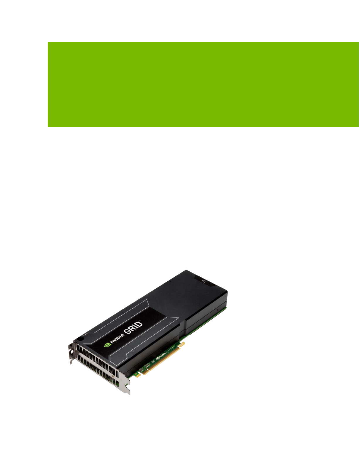
OVERVIEW
The NVIDIA GRID™ K2 is a dual-slot 10.5 inch PCI Express Gen3 graphics card with two
®
high-end NVIDIA
has 8 GB of GDDR5 memory (4 GB per GPU), and a 225 W maximum power limit. The
NVIDIA GRID K2 graphics board uses a passive heat sink that requires system airflow
to properly operate the card within thermal limits. It is designed to accelerate graphics
in virtual remote workstation and virtual desktop environments.
Kepler™ graphics processing units (GPUs). The NVIDIA GRID K2
The NVIDIA GRID K2 graphics board can be configured to enable or disable ECC (error
correcting codes) that can fix single-bit errors and detect double-bit errors. Enabling
ECC will cause some of the memory to be used for the ECC bits, so the user available
memory will decrease by 10%. ECC protection is for DRAM only.
Figure 1. NVIDIA GRID K2 Graphics Board (GK104 / P2055)
NVIDIA GRID K2
Graphics Board BD-06580-001_v02 | 1
Page 6

KEY FEATURES
GPU
Two GK104 GPUs
Number of processor cores: 1536 per GPU
Core clock: 745 MHz
Board
PCI Express Gen3 ×16 system interface
Physical dimensions: 4.376 inches × 10.5 inches × 1.52 inches (dual-slot)
Board power: 225 W (maximum)
Power Connectors
One 6-pin PCI Express power connector
One 8-pin PCI Express power connector
Overview
Memory
Memory clock: 2.5 GHz
Interface: 256-bit
● Total board memory: 8 GB (4 GB per GPU)
● 32 pieces of 128M × 16 GDDR5, SDRAM (per GPU)
BIOS
2 MBit Serial ROM
Virtualization Solutions
Citrix XenServer + XenDesktop with HDX 3D Pro
Citrix XenServer with NVIDIA NVIDIA GRID Hypervisor + XenDesktop with HDX
Microsoft Windows Server 2012 + RemoteFX
Microsoft Windows Server 2008 R2 + RemoteFX
VMware ESXi + View with vSGA
NVIDIA GRID K2
Graphics Board BD-06580-001_v02 | 2
Page 7

Overview
699-52055-0010-000: Airflow intake from bracket
CONFIGURATION
The NVIDIA GRID K2 graphics board is available in the following configuration (Table
1) based on the orientation of the airflow inside the system.
Table 1. Board Configuration
Specifications NVIDIA GRID K2
Generic SKU reference
Chip 2× GK104
Processor clock 745 MHz
Memory clock 2.5 GHz
Memory size 4 GB per GPU (8 GB per board)
Memory I/O 256-bit GDDR5
Memory configuration 32 pieces of 128M × 16 GDDR5 SDRAM
Display connectors None
Power connectors
Total board power 225 W
•
• 699-52055-0020-000: Airflow exhaust to bracket
• 1x 8-pin PCI Express power connector
• 1x 6-pin PCI Express power connector
NVIDIA GRID K2
Graphics Board BD-06580-001_v02 | 3
Page 8

MECHANICAL SPECIFICATIONS
BOARD DIMENSIONS
The NVIDIA GRID K2 board (Figure 2) conforms to the PCI Express Gen3 ×16 (4.376
inches by 10.5 inches) form factor. Figure 2 shows the board without the cover.
4.376 inches
Figure 2. NVIDIA GRID K2 Board without Cover
10.5 inches
Note: NVIDIA GRID K2 production boards will ship with a cover.
NVIDIA GRID K2
Graphics Board BD-06580-001_v02 | 4
Page 9

Mechanical Specifications
BRACKET OVERVIEW
The NVIDIA GRID K2 board features a vented bracket, as shown in Figure 3. If you are
an OEM who qualifies for bracket modifications, you have the option of receiving your
modules with no bracket installed.
Figure 3. NVIDIA GRID K2 Bracket
NVIDIA GRID K2
Graphics Board BD-06580-001_v02 | 5
Page 10

Mechanical Specifications
If you need to remove the standard bracket follow these steps:
1. Remove the two shoulder screws on the back side of the PCB.
2. Remove the two flat head screws on the bracket exhaust face.
3. Remove the bracket.
4. Slide the washer in between the PCB and the backplate to maintain clearance
between the PCB and the backplate.
5. Attach the shoulder screws.
Figure 4. Screw Locations for Attaching NVIDIA GRID K2 Br acket
Figure 5. NVIDIA GRID K2 without Bracket
NVIDIA GRID K2
Graphics Board BD-06580-001_v02 | 6
Page 11

POWER CONNECTORS
The NVIDIA GRID K2 board utilizes power from both the PCI Express connector and
the auxiliary power connectors. The NVIDIA GRID K2 board supports the following
internal connectors:
One 6-pin PCI Express power connector
One 8-pin PCI Express power connector
Figure 6 and Figure 7 shows the specifications and Table 2 and Table 3 show the pinouts
for the 6-pin and 8-pin PCI Express power connectors, respectively.
NVIDIA GRID K2
Graphics Board BD-06580-001_v02 | 7
Page 12

Power Connectors
Figure 6. 6-Pin PCI Express Power Connector
NVIDIA GRID K2
Graphics Board BD-06580-001_v02 | 8
Page 13

Power Connectors
Figure 7. 8-Pin PCI Express Power Connector
NVIDIA GRID K2
Graphics Board BD-06580-001_v02 | 9
Page 14

Table 2. 6-Pin PCI Express Power Connector Pinout
Pin Number Description
1 +12 V
2 +12 V
3 +12 V
4 GND
5 Sense
6 GND
Table 3. 8-Pin PCI Express Power Connector Pinout
Pin Number Description
1 +12 V
2 +12 V
3 +12 V
4 Sense1
5 GND
6 Sense0
7 GND
8 GND
Power Connectors
NVIDIA GRID K2
Graphics Board BD-06580-001_v02 | 10
Page 15

Power Connectors
POWER SPECIFICATIONS
The NVIDIA GRID K2 board utilizes power from the PCI Express connector as well as
one or two auxiliary power connectors. Table 4 lists the supported configurations
Table 4. Configurations with External PCI Express Connectors
Connector Type 6-Pin Power Connector Supported Notes
8-pin connected 6-pin connected Yes
8-pin connected No cable installed Yes 8-pin cable must supply 150 W
6-pin connected N/A No 6-pin cable in the 8-pin
connector is not supported.
Not installed N/A No 8-pin connector should always
be connected.
Note: If the auxiliary power cables are connected in an unsupported configuration, the NVIDIA GRID K2
board will power up in a low performance mode. The software will de t e ct and re p ort the incorrect
power connections so actions can be taken by th e user to resolve.
Note: The power breakdown per input rail is available to authorized system
partners in the NVIDIA GRID K2 System Design Guide (DG-06546-001).
NVIDIA GRID K2
Graphics Board BD-06580-001_v02 | 11
Page 16

THERMAL SPECIFICATIONS
The NVIDIA GRID K2 graphics board uses passive heat sinks that require system
airflow to properly operate the card within thermal limits. Table 5 provides thermal
information necessary to deliver reliable operation of the NVIDIA GRID K2 GPU. This
information is not intended to provide a specific thermal management solution.
For more detailed information regarding thermal specifications for the NVIDIA GRID
K2 board, refer to the NVIDIA GRID K2 System Design Guide (DG-06546-001).
Table 5. Thermal Specifications
Parameter Value Units
TDP reference operating points1
• Air inlet temperature (at TDP)
• Minimum airflow through opening (full ducted)
2
GPU maximum TDP operating temperature3
2
45
20
92 °C
GPU slowdown temperature (maximum Tj) 92 °C
GPU shutdown temperature 97 °C
Notes:
1
This airflow information is provided as gu idance and is valid only f o r the conditions describe d in the
NVIDIA GRID K2 System Design Guide (DG-06546-001).
2
The airflow and air inl e t temperature data provided here are ref erence points, not ab sol u te
specifications. Refer to the NVIDIA GRID K2 System Design Guide (DG-06546-001) fo r m ore details
regarding the sy stem airflow design g uidance.
3
The GPU maximum TDP operating t e m p erature is the maximu m G PU temperature at which the card is
guaranteed to operate at the total board power level.
°C
CFM
NVIDIA GRID K2
Graphics Board BD-06580-001_v02 | 12
Page 17

RELIABILITY
The mean time between failure (MTBF) ratings for the NVIDIA GRID K2 are tabulated
in Table 6. The calculation of these values uses the Bellcore’s Parts Count method in
controlled environments.
Table 6. Mean Time Between Failure (MTBF)
Condition (Bellcore Code) MTBF
Ground Benign (GB) environment, 35 °C * 232,528 hours
Ground Fixed (GF) environment, 35 °C ** 127,664 hours
Notes:
*Bellcore Code GB relates to non-mobile equ ipment used in ideal en v ir on m e n t (lab, medical, an d t est
equipment).
**Bellcore Code GF relates to non-mobile equipment used in less t h an ideal environment s ( rack mou n t or
other instrumentation or equipment used in buildings without controlled temperatures).
NVIDIA GRID K2
Graphics Board BD-06580-001_v02 | 13
Page 18

SUPPORT INFORMATION
AGENCIES
Australian Communications Authority and Radio Spectrum Management Group of
New Zealand (C-Tick)
Bureau of Standards, Metrology, and Inspection (BSMI)
Conformité Européenne (CE)
Federal Communications Commission (FCC)
Industry Canada - Interference-Causing Equipment Standard (ICES)
Korean Communications Commission (KCC)
Underwriters Laboratories (cUL)
Voluntary Control Council for Interference (VCCI)
NVIDIA GRID K2
Graphics Board BD-06580-001_v02 | 14
Page 19

LANGUAGES
Table 7. Languages Supported
Support Information
Windows Server
2008 and Windows
English (US) X X
English (UK) X
Arabic X
Chinese, Simplified X
Chinese, Traditional X
Danish X
Dutch X
Finnish X
French X
French (Canada) X
German X
Italian X
Japanese X
Korean X
Norwegian x
Portuguese (Brazil ) X
Russian X
Spanish X
Spanish (Latin America)
Swedish X
Thai X
Server 2008 R2
Linux
Note: NVIDIA’s CUDA® software is only supported in English (U.S. )
NVIDIA GRID K2
Graphics Board BD-06580-001_v02 | 15
Page 20

Notice
ALL NVIDIA DESIGN SPECIFICATIONS, REFERENCE BOARDS, FILES, DRAWINGS, DIAGNOSTICS, LISTS, AND OTHER
DOCUMENTS (TOGETHER AND SEPARATELY, “MATERIALS”) ARE BEING PROVIDED “AS IS.” NVIDIA MAKES NO
WARRANTIES, EXPRESSED, IMPLIED, STATUTORY, OR OTHERWISE WITH RESPECT TO THE MATERIALS, AND
EXPRESSLY DISCLAIMS ALL IMPLIED WARRANTIES OF NONINFRINGEMENT, MERCHANTABILITY, AND FITNESS FOR
A PARTICULAR PURPOSE.
Information furnished is believed to be accurate and reliable. However, NVIDIA Corporation assumes no
responsibility for the consequences of use of such information or for any infringement of patents or other
rights of third parties that may result from its use. No license is granted by implication of otherwise under
any patent rights of NVIDIA Corporation. Specifications mentioned in this publication are subject to change
without notice. This publication supersedes and replaces all other information previously supplied. NVIDIA
Corporation products are not authorized as critical components in life support devices or systems without
express written approval of N VIDIA Corporation.
Trademarks
NVIDIA, the NVIDIA logo, CUDA, Kepler, and NVIDIA GRID are trademarks and/or registered trademarks of
NVIDIA Corporation in the U.S. and other countries. Other company and product names may be trademarks of
the respective companies with which they are associated.
Copyright
© 2012, 2013 NVIDIA Corporation. All rights reserved.
www.nvidia.com
 Loading...