

Lenord+Bauer MotionPLC GEL 8240, MotionPLC GEL 8241, MotionPLC GEL 8245, MotionPLC GEL 8246 Technical Information
Page 1
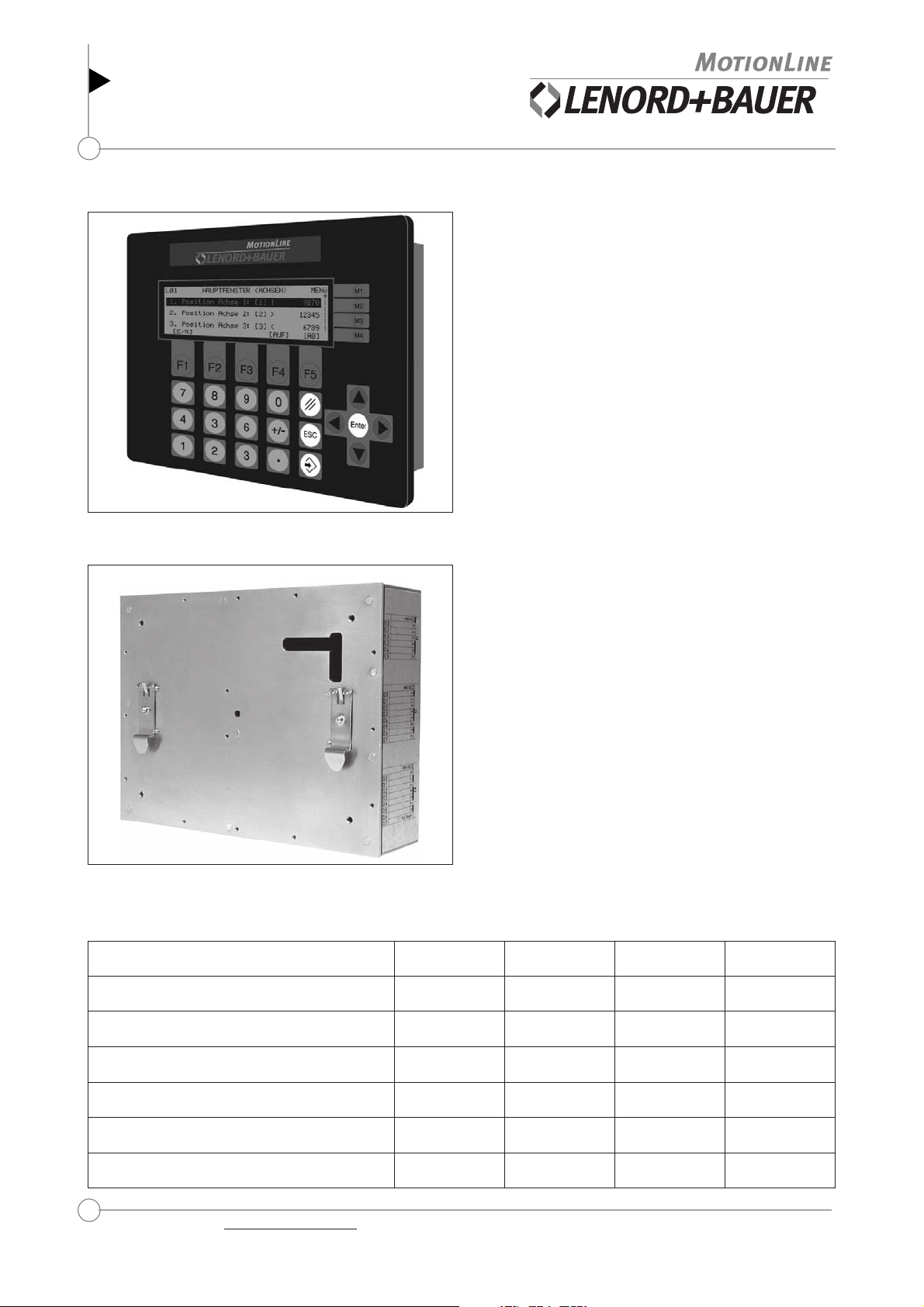
Multi-function control
MotionPLC GEL 8240/8241
GEL 8245/8246
PLC and cam-plate functionality
Technical information
▲ GEL 8240/8241
version 04.05
General information
The controllers have an integrated PLC, field bus systems
and multi-axis control with a maximum of 11 controlled
axes (max 3 with ± 10 V and max. 8 with CAN bus). 64 axes
altogether can be controlled via the CAN bus (without
feedback). Additional inputs and outputs permit several
CAN REMOTE I/Os with up to 64 inputs or outputs per
node and up to 64 node addresses.
The standard CoDeSys programming environment runs in
parallel with the multi-axis control and offers full
transparency for all parameters. Parametrization of all 7
axes is effected by a PC tool and offers menu-guidance for
comfortable setting of the usual parameters.
The standard programming environment in acc. with IEC
61131-3 includes a library of ready-made and powerful
technology functions for terminal programming and
automatic motion control.
Up to four different communication channels are available
with one interface enabling all conventional field bus
systems (PROFIBUS-DP, DeviceNet,...) to be used.
The field bus modules can be retrofitted or replaced at any
time without the need to modify the PLC program.
The MotionPLCs differ only in design (see below).
▲ GEL 8245/8246
Device variants
stupnilatigiD22032203
stuptuolatigiD51515151
Characteristics of the MotionPLCs
GEL 824x
• - RAM: 1 MBytes altogether
- NVRAM: 8 kByte altogether
- Flash: 1 MByte altogether
- free memory space for PLC applications: 256 kBytes
• 2 CAN bus interfaces
(servoconverter, CAN REMOTE I/O module)
• 2 asynchronous interfaces
(one optionally RS 232 or RS 485 and RS 422)
• high noise immunity due to electrically isolated digital
and analog inputs and outputs
• 3 encoder inputs (SSI, incremental, 5 V / 24 V)
• short projecting times due to ready-made functional
blocks and pre-configured inputs and outputs
0428LEG1428LEG5428LEG6428LEG
lenapyekdnaDCLseyseyonon
stupnieugolanA1313
stupni001TP0404
stuptuoeugolanA 3333
Internet: http://www.lenord.de Tel.: +49 (0)208 9963-0 Lenord, Bauer & Co. GmbH
E-Mail: info@lenord.de Fax: +49 (0)208 676292 Dohlenstrasse 32
46145 Oberhausen, Germany
Page 2
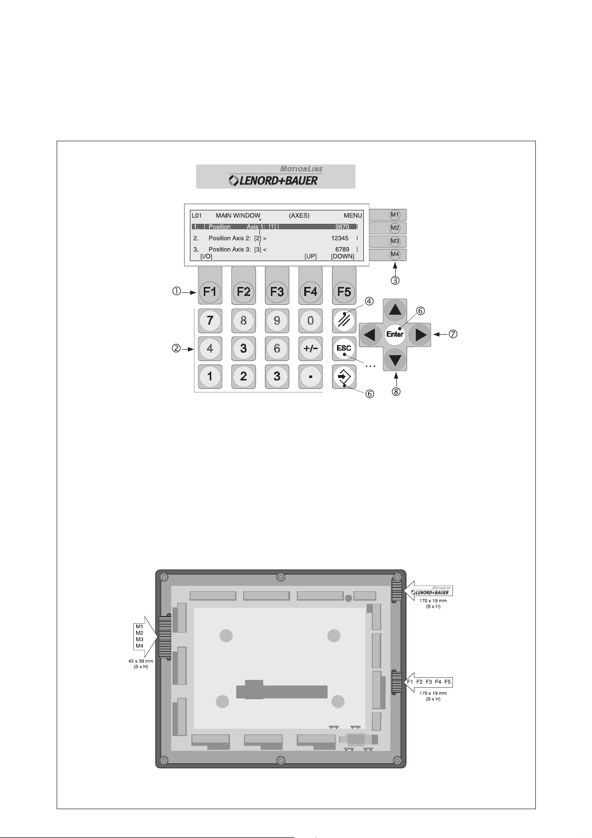
GEL 8240/8241(built-in device)
Key panel and rear view
Key panel
Rear view
Function keys (key assignment depending on active window)
Numerical keys
Menu keys
Delete entered value
Abort entry/function and return to next higher menu level
Confirm entry
Selection keys
Scrolling keys
Using your own labelling strips, the inscription of the keys in groups
the company logo can be adapted to individual needs.
and and
2 Lenord +Bauer
DS22-824x(04.05)
Page 3
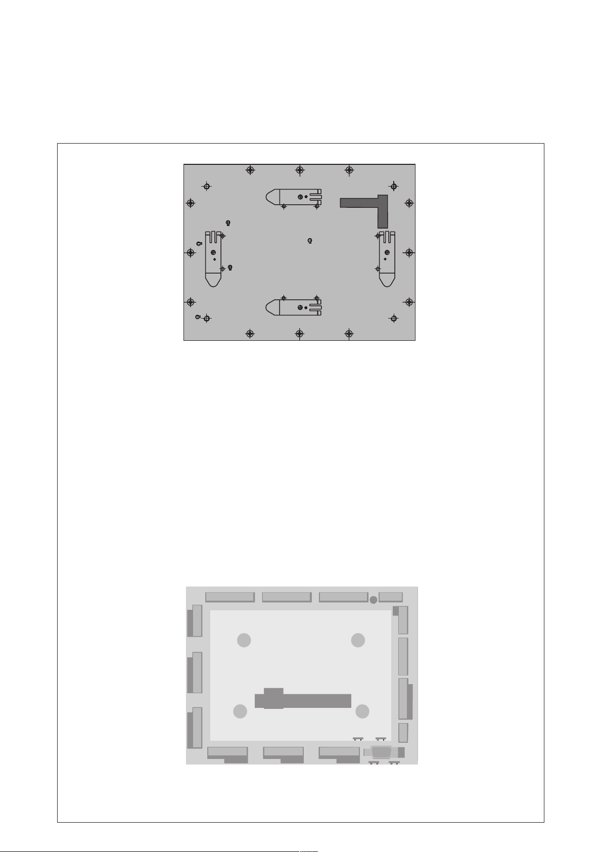
Rear view
GEL 8245/8246 (top hat rail assembly)
Front- and rear view
a
Befestigungselemente für DIN-Hutschienen
Gehäusemontage senkrecht
a
Befestigungselemente für DIN-Hutschienen
a
Gehäusemontage waagerecht
a
a
Front view
DS22-824x(04.05)
Lenord +Bauer 3
Page 4
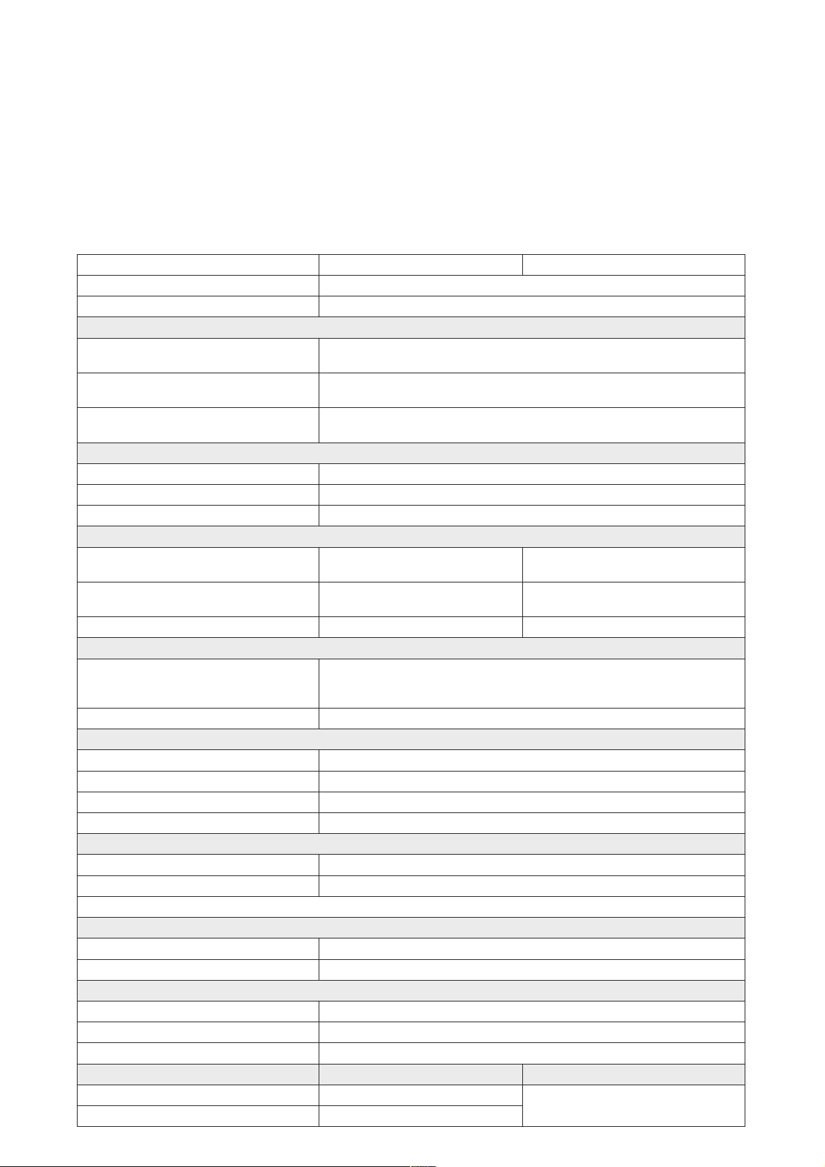
Technical data
egatlovylppusCDV03...91
noitpmusnocrewop )ecafretninognidneped(.xamA1
laires
subNAC
tolsnoisnetxe
)noitacinummoc(
stupnignitnuoc elbanibmocyleerf)ISS,V42,V5(etulosbarolatnemercni3
ycneuqerftupni.xamzHk002
gnidaolylppusrosnes latotniAm006,V5/Am009,V42
stupnilatigid
(stupnieugolana)noitulosertib01.xamylevitanretlaelbatceles,1
stupni001TP
stuptuolatigidAm03,V42x9
stuptuoeugolanaI,V01±x3
egnarerutarepmetgnikrowC°05+...°0
egnarerutarepmetgnitarepoC°05+...C°02-
egnarerutarepmetegarotsC°07+...C°02-
ytidimuhevitalernoitasnednocon,%59otpu
snoissimecitengamortcele2-18005NENID
ytinummicitengamortcele2-6-00016NENID
yalpsid gnithgilkcabDELhtiwslexip042x46htiwyalpsidCL
aeraelbisivmm93xmm331
gnisuoH
lairetamgniteehsleetsdezinavlag
lenaptnorfmuinimuladetcetorp-egde
thgiewgk7.1.xorppa
05004NIDssalcnoitcetorP
edistnorf
edisraer
4 Lenord +Bauer
5428/0428LEG6428/1428LEG
)detarapesyllacinavlag(secafretnI
584SRro224SR,C232SRsaelbasu,C232SRowt
)gnimmargorpronoitacinummoc(
)noitasinorhcnys,lortnoc,kcabdeef(
)detarapesyllacinavlag(stupnI
)detarapesyllacinavlag(stuptuO
04004NIDot.cca)FWK(yrogetacnoitazilitucitamilC
)snoitcurtsniylbmessaehtfoecnavresbo(VME
)1428/0428LEGylno(yalpsiD
etarduabelbatsujda
)knilNACdnanepoNAC(owt
tseuqernosrehtorofdna
)detarapesyllacinavlag,stupnieulav-lautca(stupniredocnE
ybnoitacidnisutats,V42x22
DELneerg
)Am02...0roV01...0(
-)C°053+...C°04-(4
Am005,V42x6
DELderybnoitacidnisutats
xam
1428/0428LEG 6428/5428LEG
56PI
02PI
teNeciveD,S-suBretnI,PDSUBIFORP:eludomsubdleifenoroflanoitpo
ybnoitacidnisutats,V42x03
DELneerg
ylevitanretlaelbatceles,3
)Am02...0roV01...0(
Vm2noituloser,Am01=
.kramECehthtiwdedivorpdnaCEE/633/98CMEevitceridUEotmrofnocsisecivedllA
02PI
DS22-824x(04.05)
Page 5
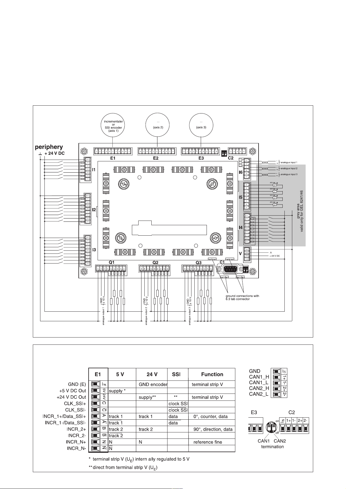
Pin layout
Terminal strip E1, E2, E3
(actual-value for axis 1, 2 or 3)
DS22-824x(04.05)
Terminal strip C2
(CAN bus)
Lenord +Bauer 5
Page 6
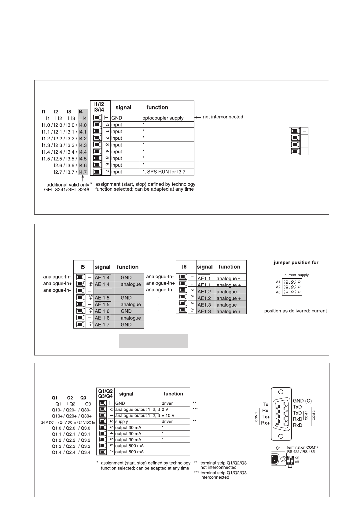
Pin layout
GND (E)
GND
24 V DC
24 V DC (E)
U
E
U
B
B
E
Terminal strip I1, I2 , I3 and I4 (digital inputs)
Terminal strip V
(supply 24 V)
= logical supply
U
B
= encoder supply
U
E
Terminal input I5 (analogue input)
PT 100 inputs (-40 ... + 350 ° C)
Terminal strip Q1, Q2, Q3
(outputs for axis 1, 2 or 3)
Terminal input I6 (analogue input)
(0 ... + 20 mA or 0 ... + 10 V)
grey area
valid only for GEL 8241/8246
Connector C1
(9-pole sub-D miniature connector)
6 Lenord +Bauer
DS22-824x(04.05)
Page 7
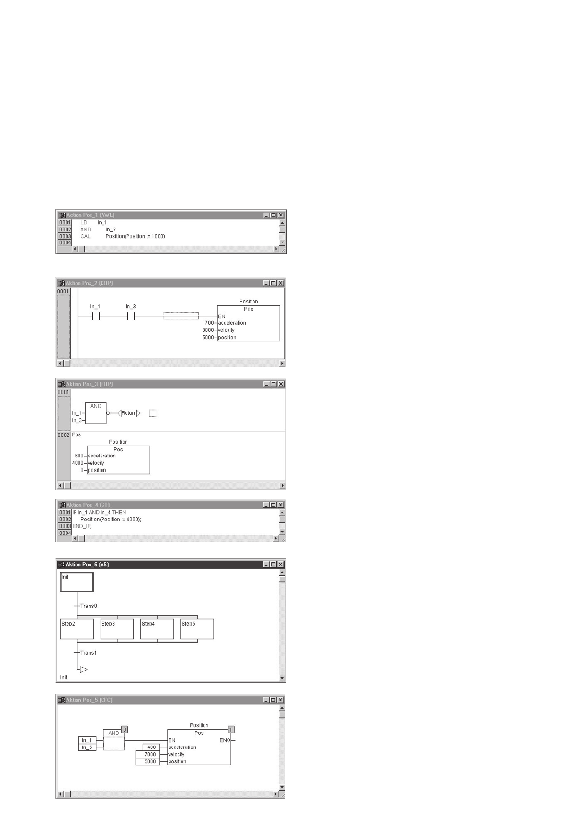
PLC programming environment
PLC programming environment
IEC 1131-3 is an international standard for programming
languages adapted to stored-program control units. The
programming languages realized in CoDeSys are in
conformity with the requirements of the standard. They
can be mixed whenever needed and are partially
convertible.
Instruction list (IL)
An instruction list (IL) is composed of a sequence of
instructions. Each instruction begins in a new line and
consists of an operator and - depending on the type of
operation - of one or several operands separated by
commas.
Ladder diagram (LD)
The ladder diagram, too, is a graphics-oriented programming language which is basically similar to an electrical
circuit.
It consists of a series of networks. A network is limited on
the right and left side of the plan by a vertical current path.
In between, there is a circuit comprising contacts,
inductances and connecting lines.
Function block diagram (FBD)
The function block diagram is another graphics-oriented
programming language. It is organized by lines and uses a
list of networks, each containing a structure representing
respectively a logical or an arithmetical expression, the
recall of a function block, a jump or a return instruction.
Structured text (ST)
The structured text is a series of instructions which can be
executed - as in the higher programming languages depending on a condition („IF..THEN..ELSE“) or iteratively
(WHILE..DO).
Sequential function chart (SFC)
The sequential function chart is a graphics-oriented
language to describe the sequential execution of different
actions in a program.
DS22-824x(04.05)
Continuous Function Chart Editor (CFC)
The essential difference with regard to the FBD is the free
arrangement of function blocks. CFC is a useful
enlargement of the IEC 1131-3 standard.
Lenord +Bauer 7
Page 8
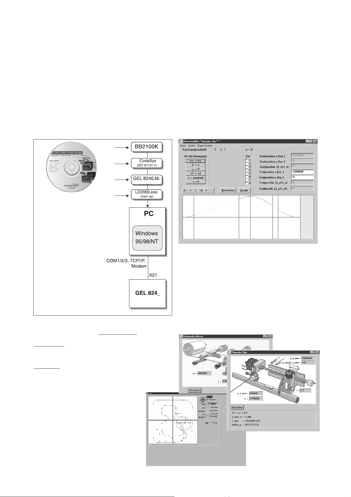
Operating software
Technological cam-plate function
• Curve modification without set-up times
• Reduced jerking during movements due to harmonic
and cycloid curve shapes
• Engagement and disengagement of the slave axis
• Virtual master function:
permits displacement of the curve drive
• Dynamic adaptation of curve shapes:
lengthening, shortening, etc.
within the scope of supply
BB2100K operating software (curve editor)
The BB2100K operating software can be used to define
the desired curve characteristics on a PC. The PC is
connected to the MotionCard via the serial interface. The
parameter editor for the servo-converter LD 2000 can also
be started out of this program. Other program
characteristics:
− System parameter editor
− Oscilloscope function
Available on our homepage
bb2100k.exe Curve editor BB2100K for operation and
monitoring of servo-converter LD 2000
with cam-plate module.
ld2000.exe Start-up software for servo-converter
LogiDrive LD 2000
www.lenord.de:
− Setting of range signals via mouse-click
− Individual programming due to free editing of program
texts
− Assistance with the analysis of curves (position,
speed, acceleration and torque)
− Graphics-aided editing of parameters for special
applications (e.g. rotating cutter and flying saw)
8 Lenord +Bauer
DS22-824x(04.05)
Page 9
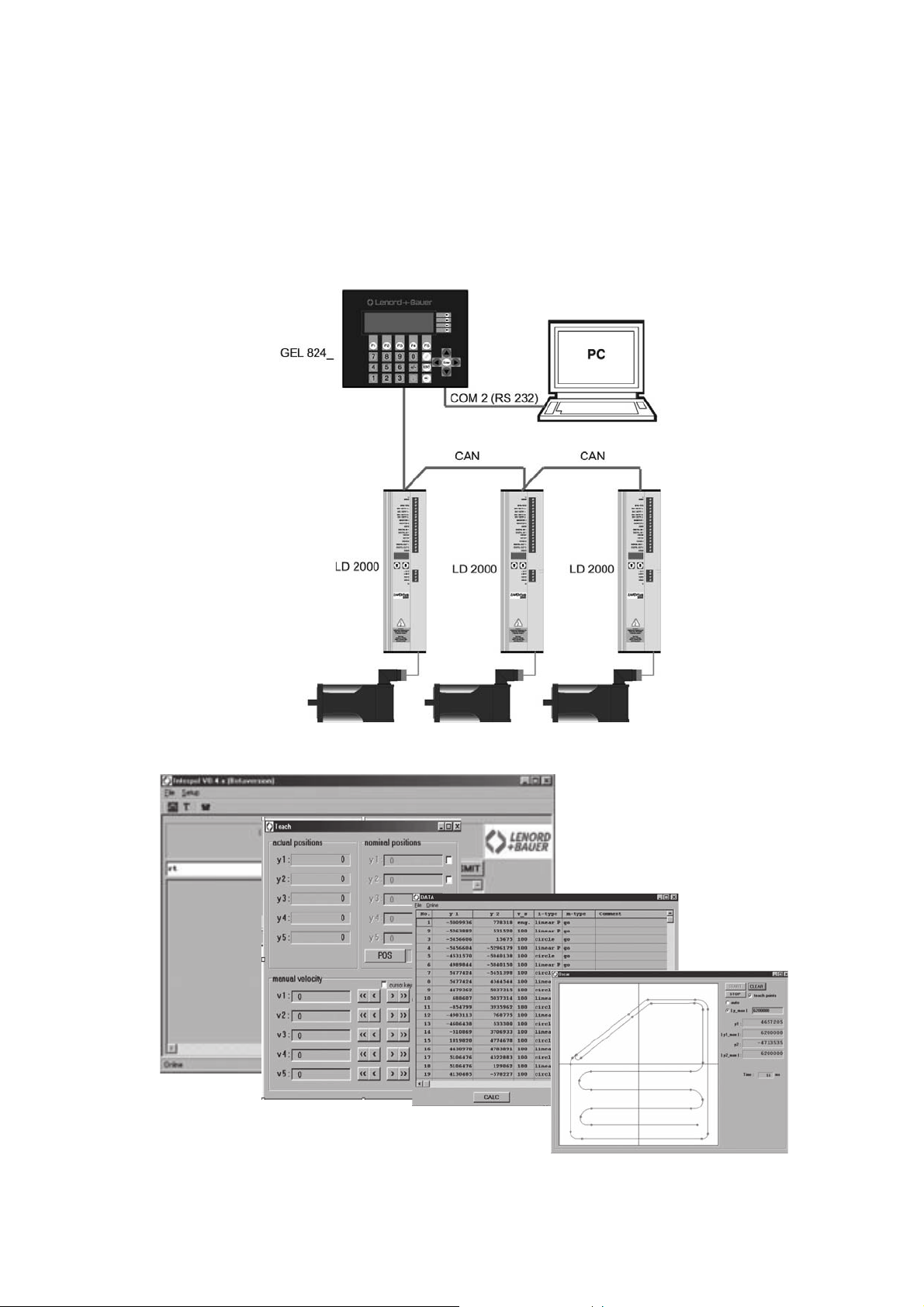
Application example
Application of adhesive on a car door
An glue dispenser with a three-axis portal equipped with servo drives and amplifiers is controlled by the MotionPLC in
such a way that the tool follows a trajectory in three dimensions which has been fixed beforehand by a small number of
essential tool center points in the teach-in mode.
Control components communication interlink
The PC tool for contour tracking (teach-in example)
DS22-824x(04.05)
Lenord +Bauer 9
Page 10
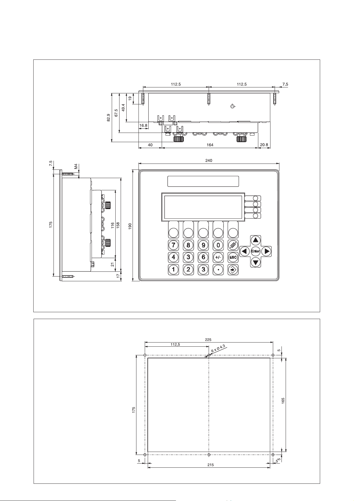
Dimension GEL 8240/8241 (built-in device),
Control panel cut-out
Dimension GEL 8240/8241
Control panel cutout
10 Lenord +Bauer
DS22-824x(04.05)
Page 11
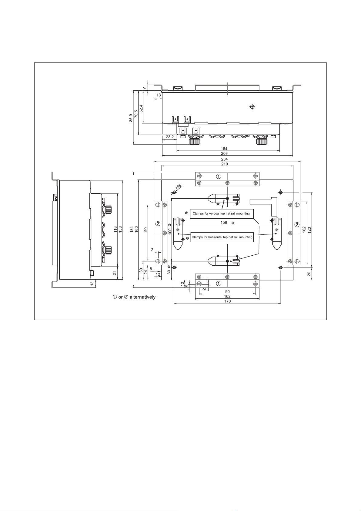
Dimension GEL 8245/8246
Dimension GEL 8245/8246
(top hat rail mounting)
DS22-824x(04.05)
Lenord +Bauer 11
Page 12
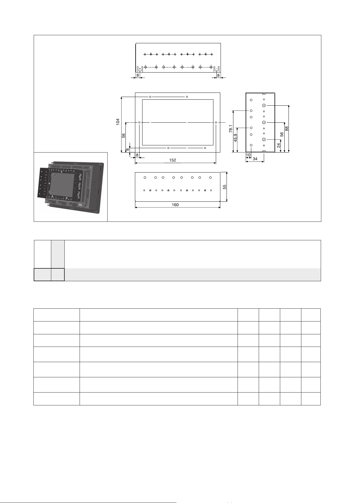
Order details
Mounting frame GK 2063
(for vertical cable outlet)
Type code
0
1
5
6
428 _
yalpsidCL
Accessories (included in scope of supply)
.on-elcitranoitpircsed0428142854286428
24098LEGtesgulpretnuocXX
34098LEGtesgulpretnuoc XX
2264GB
3264GB
4264GB
.....001DLDC0428LEGtuobaMOR-DC XXXX
stupnilanoitiddadnayalpsidCL
gnitnuomliartahpotehtrofyalpsidCLon
stupnilanoitiddadnagnitnuomliartahpotehtrofyalpsidCLon
,edirbelbac41,01x3Mswercsxeh41
,srehsawkcoldehtoot41,slanimretgnihtrae2
,rehsaw6,4Mswercsxeh6
slanimretgnihtrae2,srehsawgnirps6
6x3Msneercsxeh6,stekcarbgninetsaf2
slanimretgnihtrae2,srehsawgnirps6
XXXX
XX
XX
Accessories (optional)
GEL 89022 RS 232 C connection cable between
PC and MotionPLC
GEL 89130 fieldbus module (PROFIBUS-DP)
GEL 89131 fieldbus module (InterBus-S)
GEL 89132 fieldbus module (DeviceNet)
GK 2063 mounting frame:
6 hex screws M3 x 10
6 tooth lock washers
DS12-824X manual GEL 824X
12 Lenord +Bauer
Subject to technical modifications and typographical errors.
For the latest version please visit our web site : www.lenord.de.
DS22-824x(04.05)
 Loading...