

Page 1
GB
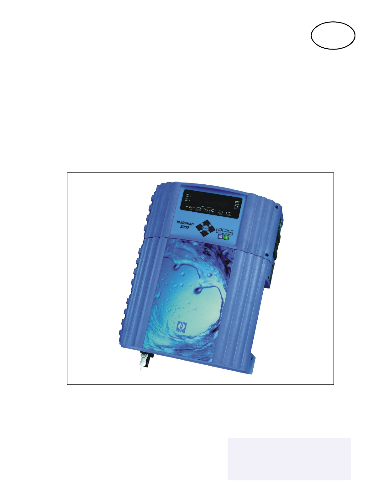
TESTOMAT® 2000 THCl
Combined Process-Photometer for total chlorine 0 - 2.5ppm
and Process-Titrator for water hardness 0.25 - 2.50°dH
Operating Instructions
Lenntech
Lenntech
info@lenntech.com Tel. +31-152-610-900
www.lenntech.com Fax. +31-152-616-289
info@lenntech.com Tel. +31-152-610-900
www.lenntech.com Fax. +31-152-616-289
Lenntech
Page 2

Contents
Introduction ..................................... 1
Short description ................................ 1
Notes for the user ................................ 2
Notes about the operational reliability ............... 2
Safety notes .................................... 2
Installation and commissioning .................... 3
Installation ..................................... 3
Electrical connection ............................. 3
Mains water supply .............................. 3
Water to drain ................................ 3
Commissioning ................................. 4
Installation diagram (example) ................... 4
General description .............................. 5
Internal construction ............................. 5
Description of the electrical connections .............. 6
Terminal block identification ..................... 6
Description of displays and operating features ......... 7
Display functions ................................ 7
Status of limit value displays ..................... 7
Measured value display ......................... 7
Limit value display ............................. 7
Alarm and maintenance message ................. 7
Status display .................................. 8
Description of the relay outputs ..................... 8
(Flush) External flush valve ...................... 8
LV1 and LV2 Limit value outputs ................. 8
1 or 2 Measuring points switch-over ............... 8
AUX Programmable function output ............... 9
Alarm fault message output ..................... 9
Maintenance message ......................... 9
Description of the signal inputs and outputs .......... 10
Start external analysis start ..................... 10
Stop external analysis stop ..................... 10
IN1 and IN2 universal inputs .................... 10
OUT Interface ouput (optional) .................. 10
Function characteristics ......................... 11
Mode of operation .............................. 11
Analysis cycle ................................. 11
Displayed unit ................................. 11
Measuring points switch-over ..................... 11
Setting the timer ................................ 12
Monitoring of limit value .......................... 12
Hysteresis .................................... 12
Logic functions ................................. 13
Function IN1 .................................. 13
Alarm / Message ............................... 13
Function AUX .................................. 14
Service II ..................................... 14
Reset operating time .......................... 14
Maintenance interval .......................... 14
Interfaces (optional) ............................. 14
Structure of the menu ........................... 15
Selection and input ............................. 15
Start menu .................................. 15
Selection ................................... 15
Input ...................................... 15
End menu .................................. 15
Information menu "i" ............................ 16
Structure of the "i" menu ......................... 16
Call .......................................... 16
Customer service ............................... 16
Operating values ............................... 16
Program values ................................ 16
Error registration ............................... 16
Maintenance .................................. 16
Program menu "M" .............................. 17
Service I ...................................... 17
Input reagent ................................ 17
Manual operation ............................. 17
Confirm maintenance ......................... 18
Diagnosis .................................. 18
Date/time of day ................................ 18
Basic program ................................. 18
Program values ................................ 18
Structure of the basic program .................... 19
Error messages / trouble shooting ................. 20
Further information ............................. 21
Maintenance ................................... 21
Description of maintenance work ................... 21
Cleaning the measuring chamber & sight-glass windows 21
Cleaning the filter housing ....................... 21
Notes on unit care .............................. 21
Spare parts list Testomat® 2000 ................... 22
Technical appendix ............................. 23
Block diagram "Testomat® 2000" ................... 23
Technical data ................................. 23
Page 3
1 / 23
Introduction
These operating instructions describe the installation, operation and programming of the combined process photometer
and titrator Testomat® 2000 TH/Cl.
We recommend that, whilst familiarising yourself with the operation of the unit aided by this manual, you have
immediate access to the unit in order to perform the functions and combinations as described. As certain functions are
interrelated, it is advisable to follow the instructions in the given order.
Should problems or questions arise which are not described in this manual and/or cannot be solved, our customer
service is always at your disposal.
Try to identify the problem as accurately as possible and record the conditions under which it has occurred. This will
enable us to offer you swift effective assistance.
Symbols and abbreviations used in these instructions:
L Note for the user "STANDBY" = STANDBY lamp is “ON”
Important to observe / warning note "M" = Press menu key M T Tip: Helpful hint
º SERVICE º MANUAL OPERATION º FLUSH = Sequence in a menu selection
Short description
The Testomat® 2000 THCl is an online monitor for monitoring the concentration of total chlorine in the measuring range
0 - 2.5 mg/l (ppm) using the colorimetric analysis principle and determines the water hardness through titration.
The analysis of total chlorine is implemented by adding three reagents, after a reaction time of approx. 1 minute
(measuring time without flush time) the analysis result is shown.
Areas of use are, e.g. the protection of reverse osmosis membranes from blocking due to hardness and from
destruction due to a high content of chlorine. Two independent programmable limit value contacts are available for
monitoring. The analysis result can be recorded using the optional printer board (interface SK910, item no. 270305) and
a dotted or continuous line printer (0/4-20mA).
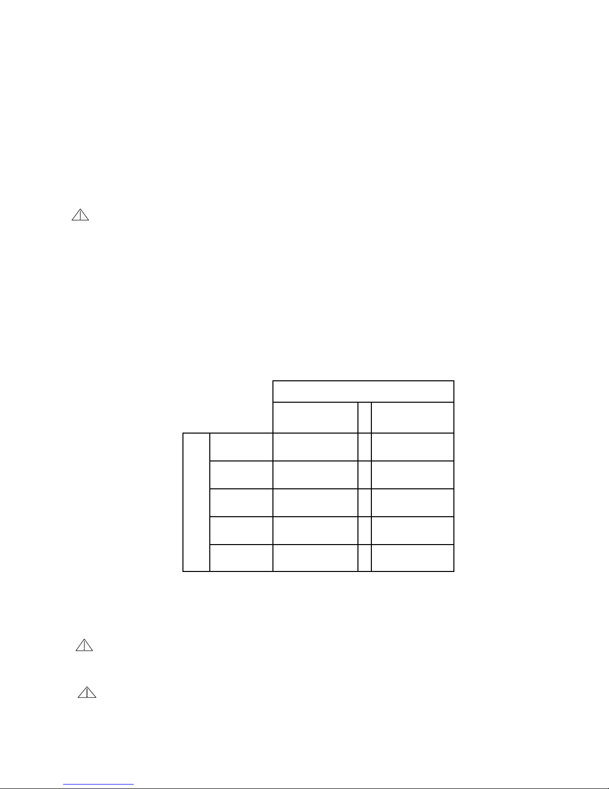
Parameter / Measuring range
water hardness
TH 2025
total chlorine
Unit
°dH
(Resolution)
0.25 - 2.50
(0.05)
-
°f
(Resolution)
0.45 - 4.48
(0.1)
-
ppm CaCO
3
(Resolution)
4.47 - 44.7
(0.9)
-
mmol/l
(Resolution)
0.04 - 0.45
(0.01)
-
mg/l (ppm)
-
0.0 - 2.5
(0.1)
L A consistently reliable result can be guaranteed by the Testomat
®
2000 units only with the use of
original HEYL Testomat® 2000 indicators and reagents! Failure or problems which are caused by the use
of different indicators are not covered by the warranty or refund services.
Larger quantities of heavy-metal ions in the softened water can affect the colour reaction, especially iron above
0.5 mg/l, copper above 0.1 mg/l and aluminium above 0.1 mg/l (brownish-red colour indication).The measuring
is possible in a range of pH 4 - 10.5.
At a concentration of more than 100 mg/l of CO2 (carbon dioxide) in the water the analysis can be affected.
Fault influences:
Concentration values of these ingredients can be determined safely and simply with our TESTOVAL® colorimetric test
comparators.
Page 4

2 / 23
Notes for the user
• Repeated switching 'on' and 'off':
Wait at least for 5 seconds before you switch the unit repeatedly 'on' or 'off' at the main switch.
• Observation of the environmental conditions:
In order to guarantee a reliable operation, the unit must only be used under the environmental conditions described
in the technical data. Protect the controller against excessive humidity, condensation and water-splash.
• Safety seal:
The original seals attached during manufacture (e.g. EPROM labels) must not be broken, otherwise all warranty
rights are lost.
• Malfunction / repair of defective units:
The repair of a defective unit is only possible when the unit is dismantled and returned to us with a description of the
fault. In addition, please inform your supplier of the reagent type used.
Before you return the unit for repair, remove the reagent bottle and ensure that the measuring chamber is flushed out
and empty.
• Electrical load capacity
The maximum electrical load capacity of the relay outputs and the total power rating must not be exceeded.
• Operate the Testomat® 2000 THCl strictly in accordance with the manufacturer's instructions.
• Environmental protection regulations
Please observe the environmental protection regulations, collect large amounts of any unused reagent which you can
no longer use and send this to us for correct disposal.
Operational checks
Careful handling of the unit increases both the operational reliability and the service life!
Therefore, the following visual inspection should be carried out at regular intervals.
• Are the hose connections with the dosing pump free of leaks?
• Is there any air inside the dosing hoses?
• Are all the water connections free of leaks?
• Are the doors of the unit properly closed? (Check door seals!)
• Is the unit unduly contaminated with dirt?
Maintenance and servicing notes
(See page 21)
Safety notes
• The unit must be installed and operated in compliance with the relevant standards (e.g. DIN, VDE, UVV), or in
accordance with the regulations laid down by the individual country.
• Some functions (e.g. the manual analysis) allow the direct manipulation of the installation without locking or
monitoring. These functions may only be used by trained staff and for this reason are only accessible after a
password has been entered.
• If you observe the unit malfunctioning, switch it off immediately. Then shut off the water supply and contact your
supplier.
• Do not attempt to repair the unit yourself (loss of warranty rights); instead always get in touch with authorised service
staff. This is the only way a reliable and safe operation of the unit can be ensured.
• After a protective circuit (fuse) has tripped, first of all, attempt to correct the cause of the malfunctioning (e.g. replace
the solenoid valve) before reactivating the protective circuit. Frequent tripping is always due to a fault which, in
certain circumstances, may also cause damage to the unit.
• Observe the safety notes about working with reagents, chemicals and cleaning agents.
Ignoring these notes can result in damage to the unit as well as to the installation and may result in a loss of
warranty rights.
Page 5
3 / 23
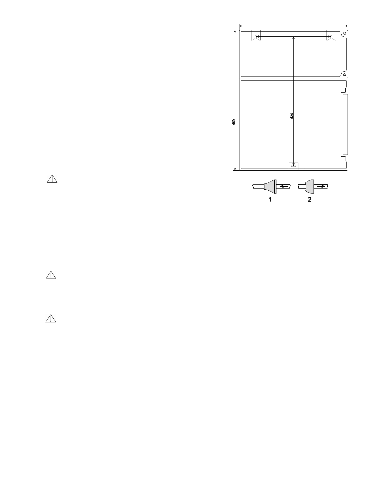
360
266
Dimensioned sketch
Installation and commissioning
Installation and commissioning must be undertaken only
by authorised technicians!
Installation
The unit should be fixed vertically!
Avoid tension of the housing.
The unit doors swing to the left when they are opened. Please
ensure that there is sufficient space for opening them. In this
way, you facilitate the electrical installation and later
maintenance and service work.
Electrical connection
Check supply voltage on the rating plate!
Basic requirement
The external cables (e.g. water meter, interface) should be kept as short as possible and clear of power cables.
Connection
Loosen both fastening screws and open the upper door. Pierce the required rubber cable glands with a screwdriver and
insert the cable (1). Then pull back the cable until the bush (2) has been turned over. Ensure that the leads are held
securely in the terminals, then close the upper door after the installation is completed using the two fastening screws.
Mains water supply
The temperature of the sample water must be between 10 °C and 40 °C. Higher water temperatures can lead to
damage to all parts coming into contact with water (e.g. filter housing, measuring chamber)!
Lower water temperatures can cause misting on the sight-glass windows.
L In the event of higher temperatures, the KCN type cooler must be installed in the branch line of the Testomat
®
2000 THCl.
Hot water can cause scalding!
The sampling tube to the Testomat® 2000 THCl must be equipped with a hand-operated shut-off valve and be kept as
short as possible (not longer than a maximum of 5 metres). It is important that the branch line connection is taken
vertically from the top of the main soft water line in order to prevent dirt particles from entering into the measuring
chamber. Remove the valve body out of the regulator/ filter housing when operating the Testomat® 2000 THCl with a
pressure range of 0.1 to 1 bar.
Plug connector
The unit is equipped as a standard with a plug connector for opaque plastic hoses 6/4 x 1 (external diameter 6 mm/
internal diameter 4 mm).
Quick-acting coupling (accessory: optional adapter for water inlet, item no. 40123)
When fabric reinforced pressure hoses (e.g. for existing installations) are used, please replace the plug connector at the
controller and filter housing with a plug for the quick-acting coupling (not included with the delivery).
Water to drain
The feed water flows through the measuring chamber then, via the outlet pipe, to the drain (hose connection internal
diameter 14 mm). Make sure, by using a funnel for example, that the water can run freely to drain and cannot back-up
into the measuring chamber. A hose impervious to light should also be used for the drain pipe (to discourage algae
formation).
Page 6
4 / 23
Commissioning
1. Full reagent bottles must be connected before commissioning and switching on. Attach the vacuum connection onto
the reagent bottle using the union nut. Please observe the correct allocation of the reagents A, B and C to the dosing
pumps: TH2025 = DOSIClip 1 (left), Cl2025A = DOSIClip 2, Cl2025B = DOSIClip 3, Cl2025C = DOSIClip
4 (right).
2. Switch the unit 'on' and press the "STANDBY" key. In this mode, an analysis is prevented from being carried out
before a correct program has been entered which could possibly result in an error or alarm message.
3. Then bleed the dosing pump and the capillary by repeatedly pressing the "Manual" key on the dosing pump. Ensure
all air is removed from the tubing! (If necessary tighten up the connections.)
4. Program the unit as applicable to your requirements, e.g.: - Mode of operation - Displayed units
- Limit values - Flush time / interval
For a description of programming see from page 17 onward.
5. Enter the correct fill status of the reagent bottles:
"M" º SERVICE Iº INPUT REAGENTS º REAGENT TH FILLING (100%)
"M" º SERVICE Iº INPUT REAGENTS º REAGENT A FILLING (100%)
"M" º SERVICE Iº INPUT REAGENTS º REAGENT B FILLING (100%)
"M" º SERVICE Iº INPUT REAGENTS º REAGENT C FILLING (100%)
6. Then remove all air from the water supply side of the unit by manual flushing.
"M" º SERVICE º MANUAL OPERATION º FLUSH ("ENTER" press repeatedly).
Continue flushing until no bubbles can be seen in either the measuring chamber or the filter housing.
7. Check all connections for tightness.
8. Carry out the first analysis by pressing the "Manual" key.
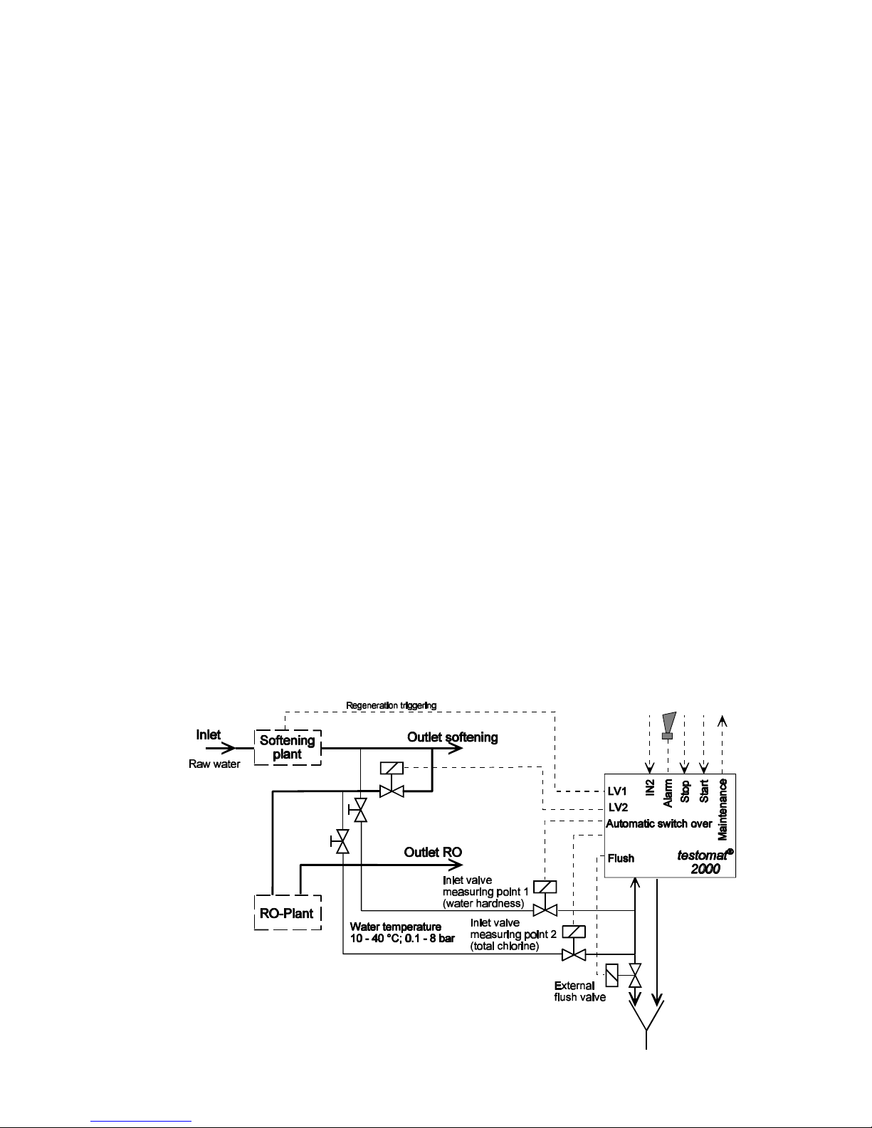
Installation (example):
Page 7
5 / 23
Terminal block for inputs
Start, Stop, IN1, IN2 and output OUT
F7 T0,08A F5 T0,2A F6 T0,315A
F8 T1A
F1 T0,1A/ 240V
F4 T0,16A
230 V
F1 T0,1A
230 V
F9 T4A
H 250 V
J6
J4 DOSI 3
J3 DOSI 2
J2 DOSI 1
J5 DOSI 4
J11
J13J8J7
E-Ventil
A-Ventil
24 V
Steckplatz Flexkabel
Messkammer
17
2
1
18
*
2
14
13
*
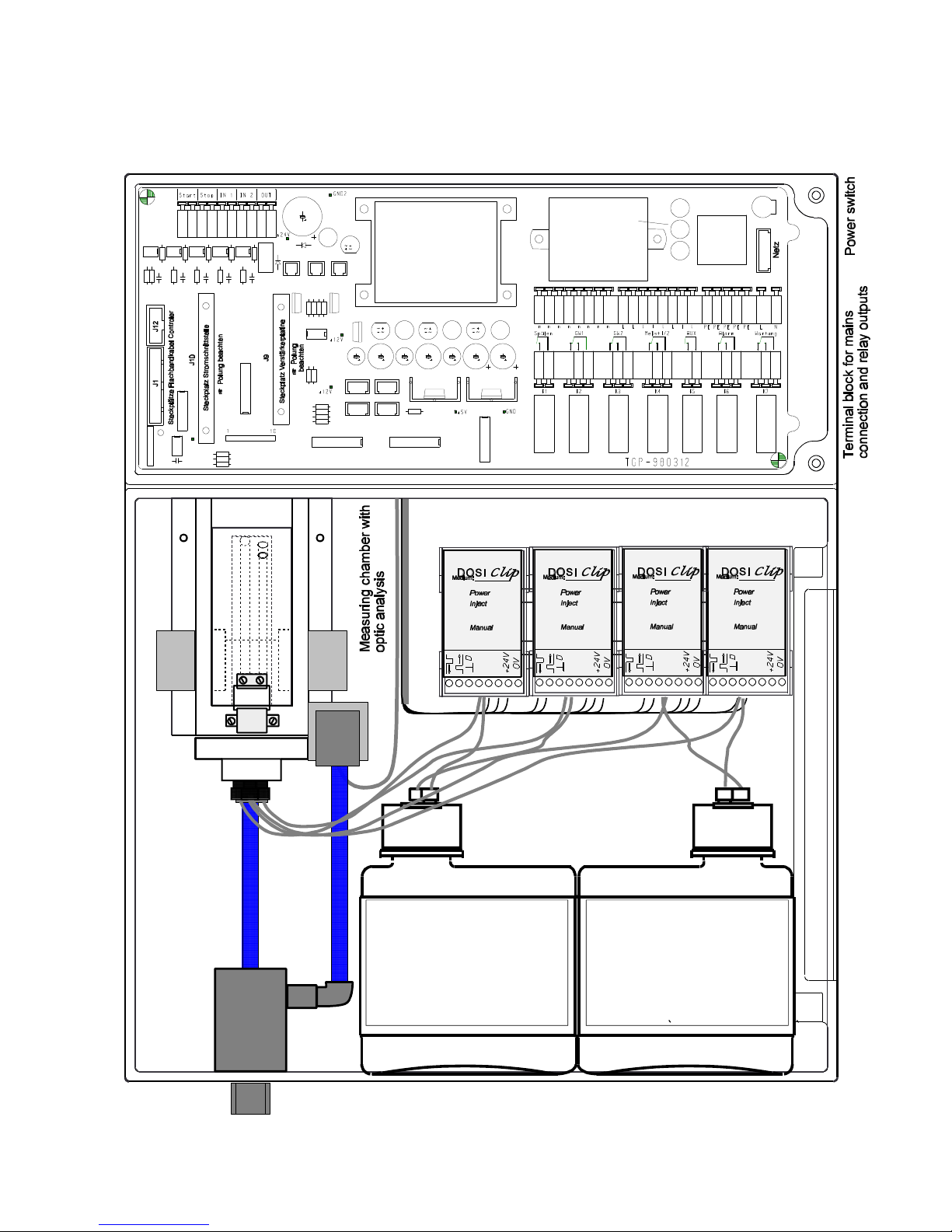
Mains water supply:
Inlet with primary filter and pressure regulator,
outlet
Valve
block
Dosing pump 1
TH2025
Plug-socket holder J4 = Dosing pump 3
Plug-socket holder J5 = Dosing pump 4
Dosing pump 2
Cl2250A
TH2025
TESTOMAT
2000
Dosing pump 4
Cl2250C
Plug-socket holder J2 = Dosing pump 1
Plug-socket holder J3 = Dosing pump 2
Dosing pump 3
Cl2250B
CL2250C
TESTOMAT
2000
General description
Internal construction
Page 8
6 / 23
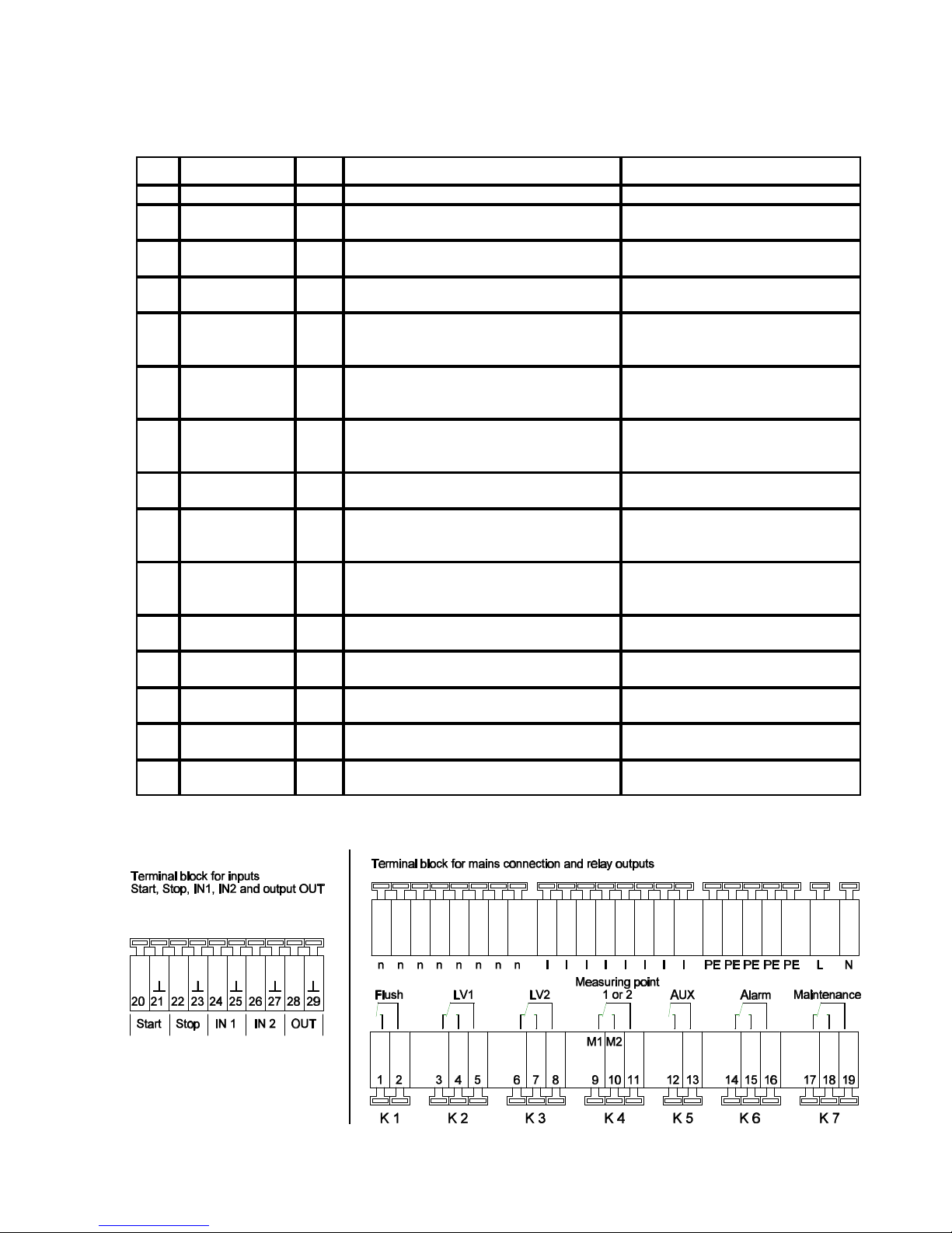
Description of the electrical connections
Terminal block identification
IN = input, OUT = output
No. Terminal Type Function Note
- PE IN Mains-Protective earth (5 x)
-
-
N
L
IN
Mains, N = Neutral
Mains, L = Live
Mains-input 230 - 240 V AC
(or 24V AC)
-
-
n
l
OUT
Neutral switched (8 x)
Mains switched (8 x)
Mains voltage, max. 4 A
1
2
Flush OUT External flush valve
Volt-free relay output
max. load 240 V AC, 4 A
3
4
5
LV1 OUT
Limit value output 1 - Normally closed
Limit value output 1 - Normally open
Limit value output 1 - Common
Residual hardness
Volt-free relay output
max. load 240 V AC, 4 A
6
7
8
LV2 OUT
Limit value output 1 - Normally closed
Limit value output 1 - Normally open
Limit value output 1 - Common
Chlorine
Volt-free relay output
max. load 240 V AC, 4 A
9
10
11
Measuring point
1/2
OUT
Measuring point 1 - Normally closed
Measuring point 2 - Normally open
Measuring point switch-over -Common
Volt-free relay output
max. load 240 V AC, 4 A
12
13
AUX OUT Universal output
Volt-free relay output
max. load 240 V AC, 4 A
14
15
16
Alarm OUT
Fault message - Normally closed
Fault message - Normally open
Fault message - Common
Volt-free relay output
max. load 240 V AC, 4 A
17
1819Maintenance OUT
Maintenance message - Normally closed
Maintenance message - Normally open
Maintenance message - Common
Volt-free relay output
max. load 240 V AC, 4 A
20
21
Start
2
IN
External analysis start
Common earth for inputs
Only for volt-free normally open
contact!
22
23
Stop
2
IN
External analysis stop
Common earth for inputs
Only for volt-free normally open/
normally closed contact!
24
25
IN1
2
IN
External measuring point switch
Common earth for inputs
Only for volt-free normally open/
normally closed contact!
26
27
IN2
2
IN
Universal input 2 (Water meter)
Common earth for inputs
Only for volt-free normally open
contact!
28
29
OUT OUT 0/4 - 20 mA or serial interface
Potential output !
28 = 0/4 - 20 mA, 29 =
2
Page 9
7 / 23
STANDBY
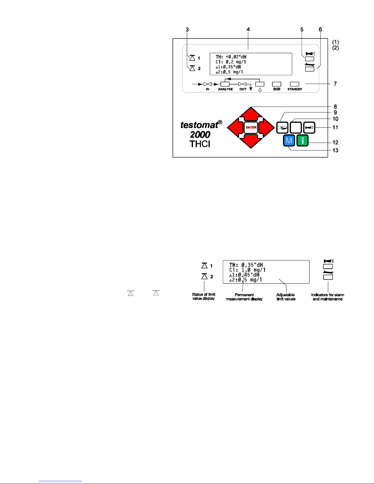
Description of displays and operating features
(1) Power switch
The 'ON'/'OFF' switch is located on the righthand side panel. Use it to switch the unit on
and off.
(2) Unit fuse (inside the unit)
Protects outputs against overload and short
circuit.
3 Status of limit value displays
Displays the status of the limit values of
residual hardness LV1 (1) and chlorine LV2 (2).
4 Text display
Displays the current analysis, all important
status results and programming data in a 4-line
LC-Display.
5 Alarm
Displays a function fault.
6 Maintenance message
Displays a maintenance request.
7 Status display
6 LEDs signal the current status (analysis and unit
status) of the Testomat® 2000 THCl.
8 Programming keys (Cursor block with ENTER)
These keys are used to enter all values and
programming data.
Function keys:
9 Manual" = manual start of analysis
10 STANDBY = manual analysis stop/standby
11 "Horn" = cancels alarm message
12 i-key
Call-up all unit information (see i-Menu).
13 M-Taste
Call-up the programming menu for user and specific unit
settings (see M-Menu).
Display functions
Status of limit value displays 1 and 2
The display signals the status of the limit values.
1: The red display lamp lights up if the limit value 1 (residual hardness) is reached or exceeded.
Lights up green if the measured value falls below the set limit value.
2: The red display lamp lights up if the limit value 2 (chlorine) is reached or exceeded.
Lights up green if the measured value falls below the set limit value.
Measured value display
The current measured value for the residual hardness (TH:) and for the total content of chlorine (CI:) are shown in line
2 and 3, e.g. TH: 0.37 °dH or Cl: 0.73ppm
When the measured value exceeds the measuring range ">" is displayed, e.g. TH:>2.50 °dH or Cl: > 2.5 mg/l
Limit value displays
The set limit values are shown in the bottom display lines 3 and 4.
1: residual hardness, 2: total chlorine
Alarm and maintenance message
Display of present error messages (red) and of present maintenance request (yellow).
L Error messages are displayed alternately with the normal display text and can only be deleted by cancellation and
correction of the fault.
Page 10
8 / 23
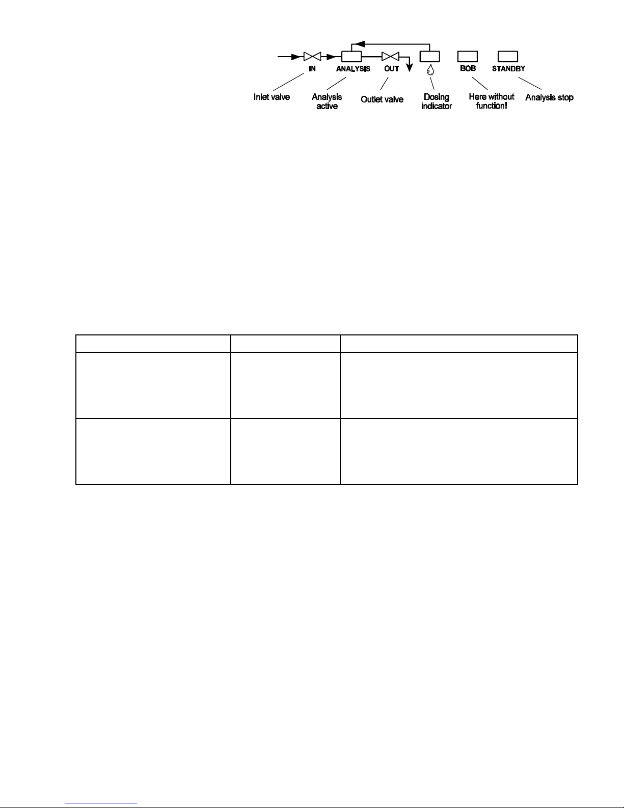
Status display
The display indicates active
unit components.
Description of relays outputs
Flush external flush valve
We recommend the fitting of a programmed flush valve upstream of the unit if, when installing the unit, the use of a long
sampling tube is unavoidable
Also, in cases where the unit is used for monitoring two measuring points, an external flush valve should be installed in
order to prevent faulty measurements caused by mixing of the samples.
Immediately before each analysis the external flush valve is opened for a programmed period, thereby allowing the tube
up to the Testomat® 2000 THCl to fill with the water to be measured. Please ensure that the programmed flush time is
sufficiently long.
The flush time is set with menu item
"M" º BASIC PROGRAM º PROGRAM VALUES º FLUSH TIMES/INTERVAL º EXTERNAL FLUSH TIME
LV1 and LV2 Limit value outputs
Two volt-free relay contacts are available for reporting that a limit value has been exceeded. For both contacts the limit
values, the hysteresis and the function can be independently programmed:
Function Type of contact Action
LV1
S active at
limit value in excess of
limit value 1 (residual hardness)
(Measuring point 1)
volt-free
change-over contact
programmable:
S Continuous contact
S Impulse (1 - 99 seconds/minutes)
S Interval (1 - 99 seconds/minutes)
S Hysteresis (1, 2 or 3 limit value in excess)
LV2
S active at
limit value in excess of
limit value 2 (total chlorine)
(Measuring point 2)
volt-free
change-over contact
programmable:
S Continuous contact
S Impulse (1 - 99 seconds/minutes)
S Interval (1 - 99 seconds/minutes)
S Hysteresis (1, 2 or 3 limit value in excess)
Menu values:
"M" º BASIC PROGRAM º PROGRAM VALUES º LIMIT VALUES
"M" º BASIC PROGRAM º PROGRAM VALUES º FUNCTION LV1
"M" º BASIC PROGRAM º PROGRAM VALUES º FUNCTION LV2
"M" º BASIC PROGRAM º PROGRAM VALUES º HYSTERISIS LV1
"M" º BASIC PROGRAM º PROGRAM VALUES º HYSTERISIS LV2
(Measuring points 1 or 2) Measuring points switch-over
If the unit is used for monitoring two measuring points, the solenoid valves (individual valves or one 3/2-way distributing
valve) must be connected to the corresponding sampling tubes. The switch-over can occur automatically: The analyses
are carried out alternately from measuring point 1 or 2.
Or via an external request: Inlet IN1 active = next analysis from measuring point 1 (hardness)
It is important that the terminals are strictly allocated to the appropriate measuring points and to the parameter to be
measured:
Terminal 9 = Measuring point 1= Residual hardness
Terminal 10 = Measuring point 2 = total chlorine
IN1 active = measurements only from measuring point 1
"M" º BASIC PROGRAM º PROGRAM VALUES º MEASURING POINTS 1/2
Page 11

9 / 23
AUX Programmable function output
The function of this volt-free relay output is programmable:
1. Message of a current analysis
"M" º BASIC PROGRAM º PROGRAM VALUES º FUNCTION AUX º CONTACT DURING ANALYSIS
and/or
2. Contact before an analysis, e. g. control of a cooler
"M" º BASIC PROGRAM º PROGRAM VALUES º FUNCTION AUX º CONTACT BEFORE ANALYSIS
or
3. Contact after an analysis
"M" º BASIC PROGRAM º PROGRAM VALUES º FUNCTION AUX º CONTACT AFTER ANALYSIS
Alarm Fault message
The "Alarm" output is a volt-free change-over relay contact. During trouble-free operation the contact between the
terminals 14 - 16 is closed and the one between terminals 15 - 16 is open. When the voltage fails, the contact between
terminals 15 - 16 is closed and the one between 14 - 16 is open.
The unit is equipped with a range of monitoring functions. You can define certain situations as a fault and program a
corresponding message either as continuous contact (A) or as a message impulse (M).
- With a continuous contact, the "Alarm" output remains activated (with terminals 15 and 16 closed) as long as the fault
persists.
- For a message impulse, the output is alternately switched 'on' for 2 seconds and then switched 'off' for 5 seconds.
- If several faults with different programmed messages are reported simultaneously, the output is switched to
continuous contact.
- The red LED "Alarm (5)" and the text on the display indicate a fault.
- The error signal at the "Alarm" output is deleted by cancelling the fault with the "Horn" key.
- An error message can only be deleted after the fault has been corrected.
- Exception: The maintenance date has been exceeded. This message is confirmed in the M-menu, see below
(maintenance).
- Each new fault is entered into the fault history (also see i-menu, page 16).
The following faults activate the "Alarm" output and are displayed:
The following conditions always trigger an error
message:
Power failure
Low-water pressure
Function fault optics
Function fault dosing pump
Function fault outlet to drain
Function fault failure 24V
Conditions which can be programmed as faults:
Indicator low level
Reagent low level (A, B, C)
Measuring fault dirtiness
Measuring fault turbid
Transfer error
Measuring range exceeded
Maintenance interval exceeded
Error messages are described on page 20.
Maintenance, maintenance message
The
"Maintenance" output is a volt-free change-over relay contact. During trouble-free operation and without a
programmed maintenance interval the contact between terminals 17 and 19 is closed and the one between 18 and 19
is open.
The unit is equipped with a range of monitoring functions and a programmable maintenance interval. The maintenance
message is always a continuous contact.
A maintenance request is displayed by the yellow "Maintenance" LED.
The maintenance display can only be deleted after the condition has been corrected, or after the maintenance request
has been confirmed.
"M" º SERVICE º CONFIRM MAINTENANCE
The following conditions activate the "Maintenance" output:
Reagent low level
Measuring chamber dirty (Measuring fault dirtiness)
Maintenance date reached
For a more detailed description of the programming refer to page 17 onward. For general maintenance refer to page 21.
Page 12
10 / 23
Description of the signal inputs and output
L Connect the signal inputs "Start", "Stop", "IN1" and "IN2" only with volt-free contacts!
Start external analysis start
Stop external analysis stop
Function Type of contact Test time Action
Start
S External analysis start
(e.g. from the process controller)
normally open
volt-free!
none
S Mode of operation EXTERNAL starts
an analysis by triggering a contact at
the input
Stop
S External analysis stop
(e.g. via flow controller or from the
process controller)
programmable
normally closed/
normally open
volt-free!
none
S As long as the contact at the input is
'open' or 'closed', no analyses are
carried out.
M" º BASIC PROGRAM º PROGRAM VALUES º INPUT STOP
IN1 and IN2 Universal inputs
Function Type of contact Test time Action
IN1
S External measuring point switch-over
(suppression of measuring point 2)
programmable
normally closed/
normally open
volt-free!
none
S As long as the contact at the input is
'open' or 'closed', the analyses are
carried out by measuring point 1
IN2
S Water meter input
normally open
volt-free!
none
S Quantity recording to start an analysis
and for plant monitoring
"M" º BASIC PROGRAM º PROGRAM VALUES º INPUT IN1
OUT Interface output (optional)
Function Terminal Test time Action
Programmable interface
S 0 - 20 mA
S 4 - 20 mA
max. load
500 Ohm
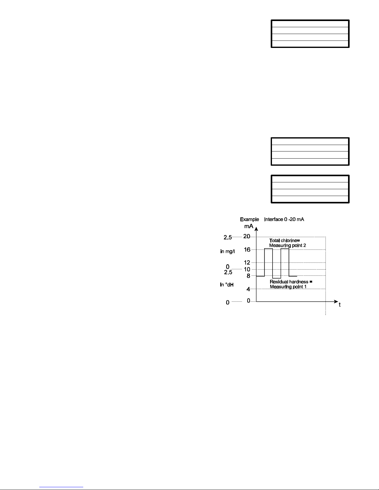
- S Measuring value residual hardness
(measuring range 0-10 / 4-12 mA)
S Measuring value total chlorine
(measuring range 10-20 / 12-20 mA)
Serial interface RS 232 serial bus
(2-cable-line)
- S See description of the plug-in circuit
card RS910
Change the function of the output by changing the plug-in circuit board.
"M" º BASIC PROGRAM º PROGRAM VALUES º INTERFACES
Page 13
11 / 23
MODE OF OPERATION
sstt
M E
External (START)
Volume interval
TIME-CONTROLLED *
DISPLAY OF UNIT Cl
s stt
M E
Display in ppm
DISPLAY IN mg/l *
4, 5, 6
7
8
3
2
2
1
Function characteristics
Mode of operation (analysis controller)
1. Time control: Internal triggering by a timer. The shortest interval = 0
minutes between analyses, longest interval = 99 minutes.
(see page 12, interval periods)
L The analysis interval is determined by the duration of the supplementary
program AUX, the set flush times (internal and external), the programmed
pause (interval) and the duration of the analysis. The analysis duration is a
direct function of the value to be measured.
2. Quantity control: Triggered by the water meter.
Minimum interval = 1 litre, maximum interval = 9999 litres.
After the programmed water quantity is measured, the analysis is carried
out. Prior to the analysis, the capillary and the measuring chamber are
flushed (observe the programmed flush times).
3. External analysis start via contact “Start” input
L The current analysis interval can be interrupted by making contact at the
"Stop" input.
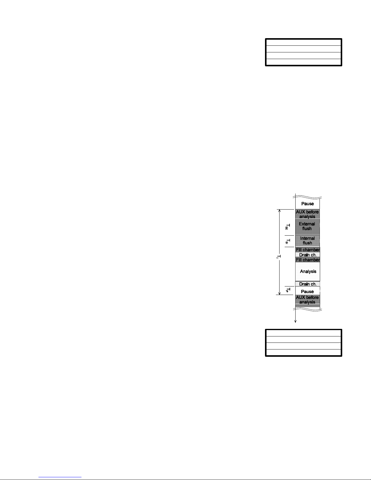
Analysis cycle (example with schematic cycle diagram)
1 Supplementary program AUX before analysis
2 Flush branch line and measuring chamber (note flush time of the sampling
line), TSE and T
SI
3 Fill measuring chamber
4, 5 Check the sample for dirtiness (stirring mechanism is "ON"),
Chlorine: Measure out reagents: 12 x reagent A, 5 x reagent B
and 2 x reagent C, then a reaction time of 2 minutes
Residual hardness: Measure out indicator (titration)
6 Evaluate and display reaction (approx. 1 minute)
7 Drain measuring chamber
8 Pause period up to the next analysis (time or quantity analysis interval), Tp.
TI = total analysis interval, ch = measuring chamber
Displayed unit
It is possible to program the units of the displayed value. You have the choice of
°dH, °f, ppm CaCO3 and mmol/l for the residual hardness and mg/l und ppm for
the chlorine. All the following inputs and displays will then be displayed in the
programmed unit.
Measuring points switch-over
The Testomat 2000 THCl enables the monitoring of 2 measuring points. The measuring points switch-over occurs
automatically, but can be suppressed by a contact at input IN1.
The active status of IN1 should be programmed correspondingly.
The parameters are assigned to the measuring points:
Measuring point 1 = Residual hardness
Measuring point 2 = Total chlorine
IN1 active = Measurements only from measuring point 1
Page 14
12 / 23
FLUSH TIMES/INTERVAL
sstt
M E
INTERNAL FLUSH TIME 00s
Interval pause 1m
External flush time 00s
LIMIT VALUES
s stt
M E
Limit val. Cl: 0.50 mg/l
LIMIT VAL. TH: 0.30°dH
HYSTERESIS LV1
s stt
M E
Analysis (1,2,3) 1
Setting the timer
Internal flush
In order to ensure the analysed sample represents the current value, the sampling
tube must be sufficiently well flushed taking its length into consideration. After the
installation has been out of operation for a longer period, or in the case of long
analysis intervals, it is sensible to select a flushing time in excess of 60 seconds. Flush is initiated by simultaneously
opening the inlet and the outlet valve of the Testomat® 2000 THCl.
L The analysis interval directly depends on the programmed flush time. If a flush time of, for example, 60 seconds is
set, the analysis interval itself cannot be shorter than 60 seconds.
External flush
An external flush valve should be installed upstream of the Testomat® 2000 THCl if very short analysis intervals are
required, the sampling tube is very long (several metres), or when using a tube with a large diameter. This is connected
to the "Flush" outlet. The external flush time for the valve depends, like the flush time for flush by the unit, on length and
diameter of the connection to the Testomat® 2000 THCl.
Example: For connections longer than 3 m and an internal tube diameter of 6 mm, a minimal internal flushing time
of 10 seconds is required to ensure a current sample is taken from the sampling tube. The quantity of
flush water for an internal flush of 1minute is 0.5 litres.
Interval pause
In the case of timed triggering of the analysis, the interval between two analyses (plus flush time) is determined by the
interval pause. The shortest interval can be 0 minutes. In this case, the analyses are carried out continuously. The
longest interval is 99 minutes.
Monitoring of limit value
The limit values can be programmed on a continuous scale. The range for the limit
value depends on the measuring range of the respective parameter.
Two outputs for the limit value are available for monitoring.
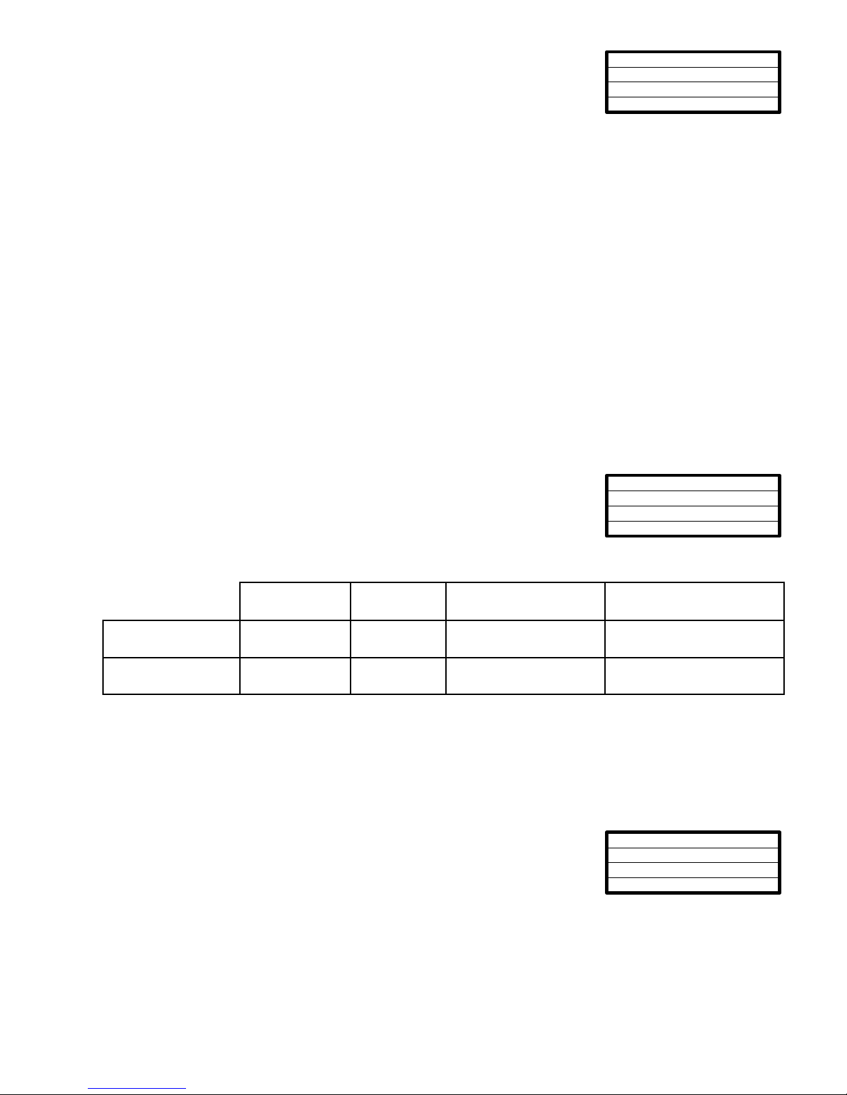
Limit value Parameter Measuring
point
Function Hysteresis
LV1 Residual
hardness
1
duration, impulse,
interval
1st, 2nd or 3
rd
exceeds
LV2 Total chlorine
2
duration, impulse,
interval
1st, 2nd or 3
rd
exceeds
The functions of these outputs can be programmed independently from each other:
If the limit value LV1 is exceeded, the limit value control display lights up LV1 RED and the relay output LV1 reacts as
programmed in the switch function. If this limit value is not exceeded, the display lights up GREEN.
The unit operates in the same way for the limit value LV2.
Hysteresis
Each limit value output reacts only after the 1st, 2nd or 3rd limit value excess
(suppression of the first or the second measured value).
This increases the reliability during the evaluation of the analysis, e.g. after the
measuring point has been switched over or if the sampling line has possibly not been
flushed sufficiently. The hystereses of the two outputs LV1 and LV2 can be set independently from each other.
Operation: With a hysteresis of 2 a further analysis is carried out immediately after the limit value has been exceeded.
Only if the limit value of this analysis is exceeded again, is the corresponding output energised. If you have set a
hysteresis of 3, the corresponding output reacts only after the limit value has been exceeded for the 3rd time in
succession.
(Basic setting is 1 for LV1 and LV2)
Page 15
13 / 23
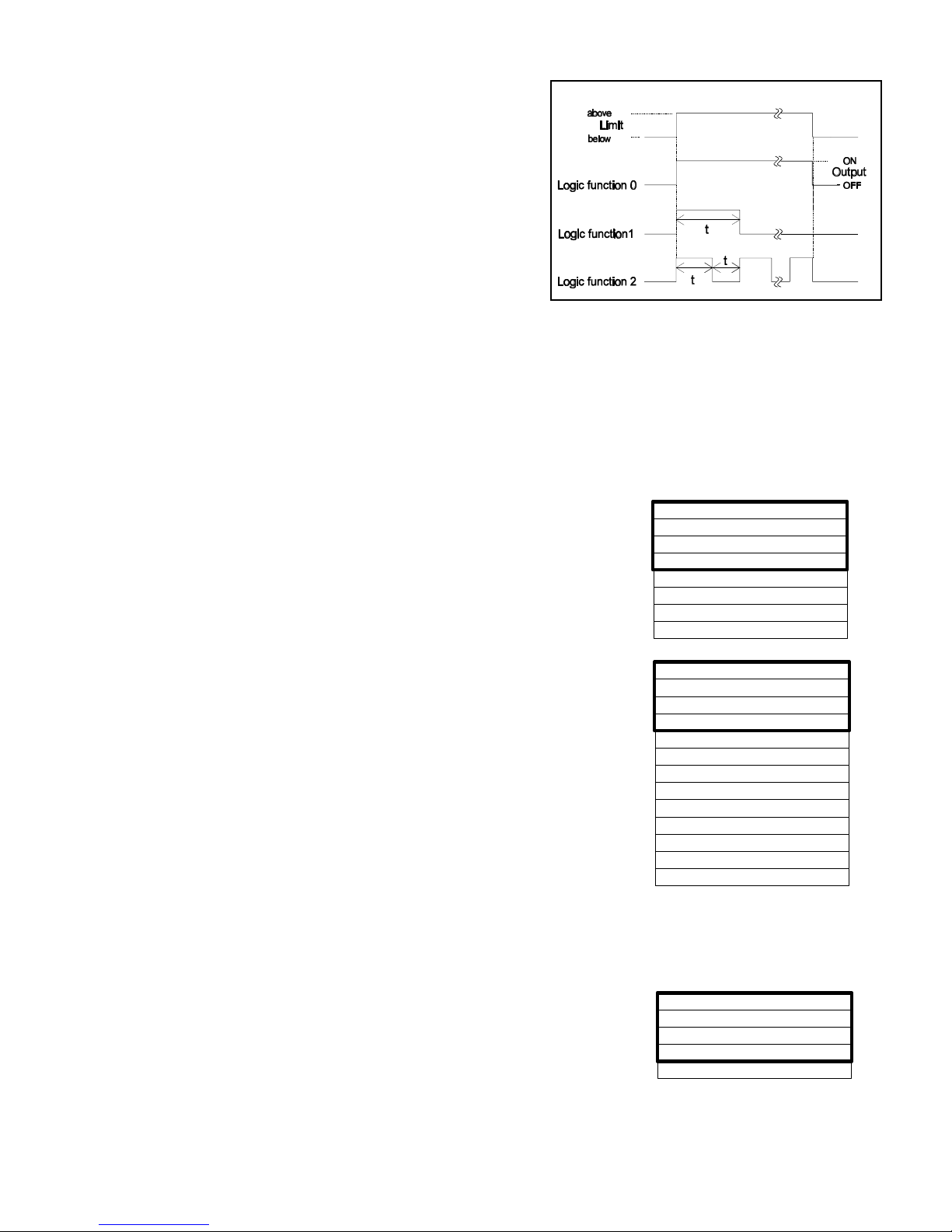
Schematic representation of logic function
TYPE OF WATER METER
s stt
M E
1 LITRE/IMPULSE
2.5 Litres/Impulse
5 Litres/Impulse
10 Litres/Impulse
100 Litres/Impulse *
500 Litres/Impulse
1000 Litres/Impulse
ALARM/MESSAGE
s stt
M E
REAGENT Cl LOW LEVEL A
Low water pressure A
Indicator TH low level A
Ff. optics A
Ff. dosing pump A
Ff. outlet to drain A
Mf. dirtiness M
power failure 24 V A
Mf. turbid M
Transfer error M
A = Alarm / M = Message / - = no action
Ff. = Function fault
Mf. = Measuring fault
A/M/A/M
A/M
A/M
A/M
A/M/-
A/M/-
A/M
A/M/-
Meas. range exceeded M
A/M/-
Maint. int. exceeded M
A/M/-
A/M/-
FUNCTION AUX
s stt
M E
Contact during analysis
CONTACT BEFORE ANALYSIS *
Contact after analysis
Time: 00m 10s
Logic functions of the limit value outputs LV1 and LV2
Logic function 0, Duration
Output relay LV1 or LV2 pulls up when the measured value rises
above limit value LV1 or LV2. If the measured value falls below
the limit value LV1 or LV2 without lock out, the relevant relay
drops out again.
Logic function 1, Impulse
If the measured value rises above limit value LV1 or LV2, the
relevant output pulls up for a set time t.
Independent of the time taken for the limit value to rise above the
set limit, the relevant output always remains in the "ON" position
for the set time.
Logic function 2, Interval
If the measured value rises above one limit value, the relevant output pulls up at intervals with the time set
(Impulse/Pause).
Function IN1
When measurements are carried out by two measurement points, the measuring points switch-over can be suppressed
by activating IN1. If IN1 is active, measurements are only carried out by measuring point 1. A corresponding controller
has to be connected to the IN1 (e.g. timer) (a volt free contact is required!). The energised status of IN1 must be
programmed correspondingly.
Water meter
For quantity dependent analysis triggering it is necessary to connect a water
meter to the IN2 input. Program the corresponding water meter rating under
menu item "WATER METER".
Alarm / Message
The unit is equipped with an alarm relay output for reporting errors. The events
which could mean a fault at the unit, or are intended to trigger a message, can
either trigger an alarm (continuous contact) or a message (2 second impulse).
For certain unit faults it is already pre-determined whether they trigger an alarm or
a message
The faults are entered into the fault history and stored if the event is programmed
as an alarm or message. For example, if reagent low is not programmed as
ALARM or MESSAGE, then it will not be registered in the fault history. Up to 20
error messages can be stored. This list can be called up via the information menu.
The information stored is the time (day, month, year and hour) and the type of the
fault.
L After a power failure, the error messages are lost.
Function AUX
The AUX relay output can be programmed for the following control functions:
S It can be programmed as a functional output for providing a contact of a
programmable duration before and/or during, or after an analysis.
For example, the cooling water flow in an upstream cooler can be controlled by means of a solenoid valve. Cooling
water will then only flow when necessary, i.e. while an analysis is being carried out.
Page 16
14 / 23
SERVICE II
s stt
M E
Reset operating time
Maintenance interval
MAINTENANCE INTERV.
stst
M E
001d
INTERFACES
st st
M E
Type 0-20 mA
Type RS232
Type 4-20 mA *
Service II
The service II menu contains a number of functions for monitoring the operation of the
unit.
L The functions in the service II menu have a direct influence on the operation, and
monitoring functions of the unit!
Reset operating time
After replacing the metering pump or the holder for the measuring chamber, the current operating time can be reset to
0 hours:
"M" º BASIC PROGRAM º SERVICE II º RESET OPERATING TIME
The current operating time can be called up in the information menu:
"i" º INFORMATION º OPERATING VALUES
Maintenance interval
The observance of the maintenance interval is monitored and displayed by the
Testomat® 2000 THCl. Program the desired maintenance interval in days.
( 0 days = no maintenance interval. )
Interfaces (optional)
Interface 0/4 - 20 mA
Another possibility for monitoring the analysis is the connection of
a recorder. For this purpose the unit is equipped with a
programmable current output.
Standard values of 0 - 20 mA or 4 - 20 mA can be selected.
L A maximum working resistance of 500 Ù must not be
exceeded!
In situations where interferences might occur, and where very
long cables are used (approx. 20 m), a screened cable should
be used if possible.
Serial interface RS232
The connection of the Testomat® 2000 to a protocol printer via the serial interface RS232 enables the print out of
measuring results and error messages. This means the analyses can be continuously recorded. This option is only
possible in conjunction with the plug in circuit card RS910 (Item No. 270310).
Page 17

15 / 23
Displayed function
"i" (Key) "M"
Information Menu Program Menu
Structure of the menu
Selection and input
Start menu
Select one of the two menus by pressing either the "M" or the "i" key.
Selection
The active line position is displayed in CAPITALS. Use the "ENTER" key to activate the line, i.e. to enter a submenu.
By using the arrow key "w", the next parameter appears below the lowest display line:
The menu can be scrolled.
Input (only possible in the "M" menu)
• Select a programming step by means of the arrow keys "w" and "v" and activate the entry function by pressing the
"ENTER" key.
• In the case of digits to be entered, the first digit to be modified flashes.
• The value can be changed using the arrow keys "w" and "v".
• By pressing the arrow keys ">" and "<", it is possible to confirm the entry and simultaneously change to the next or the
preceding digit (which then starts flashing).
• Terminate the entry function by pressing "ENTER".
• The following line is activated.
• Change to the menu one level up by pressing the "M" key.
End menu
Return to the menu one level up by pressing either the "M" or the "i" key. After returning from the highest menu level the
unit returns to the display mode.
Page 18
16 / 23
i button
CUSTOMER SERVICE i
GEBRUEDER HEYL
i
i
E
E
i
ERROR REGISTRATION st i E
Error display, if it is programmed as
alarm
MODE OF OPERATION
Displayed unit
PROGRAM VALUES st i E
Measuring points 1 or 2
Flush times/interval
Limit values
INDICATOR TH LEVEL 030%
Residual analyses 1386
Reagent B level 030%
Reagent A level 030%
OPERATING VALUES st i
Res. operat. time 00126h
D-31135 HILDESHEIM
TEL. 05121-7609-0
Maintenance
Program values
Error registration
CUSTOMER SERVICE
Operating values
INFORMATION
st
i E
Maintenance interval 000d
MAINTENANCE i
Maintenance in 000d
Up to 20
error messages
Low water pressure
Ff. optics
Ff. outlet to drain
Ff. dosing pump
Mf. dirtiness
Transfer error
power failure 24 V
REAGENT Cl LOW LEVEL
Indicator TH low level
Power failure
TH: 0.20 °dH
Cl: 0.24 mg/l
^1: 0.20 °dH
^2: 0.40 mg/l
E
i
1
2
3
4
5
6
i
E
POWER FAILURE i
E
Reagent C level 030%
4 lines are displayed
(black scale)
Water quantity 0063m
3
Software version 48EXXX
Operating time 00629h
i
E
to
From
Information Menu "i"
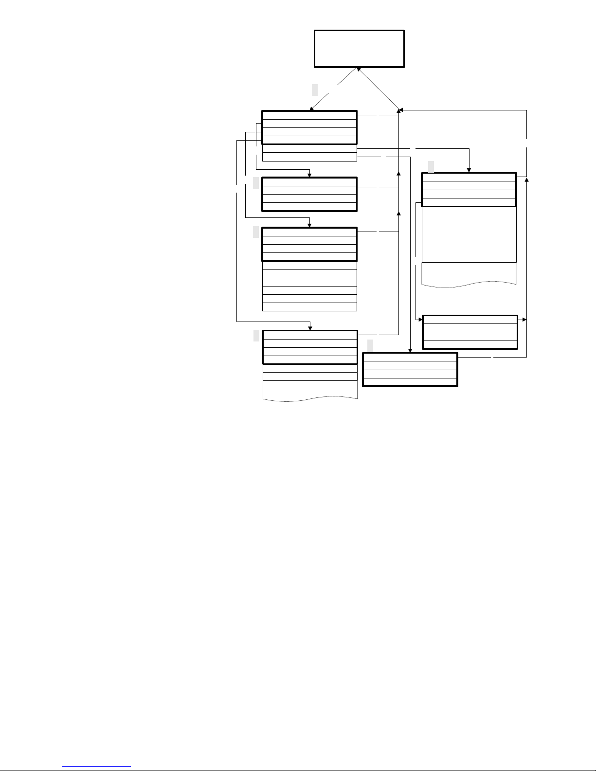
Structure of the "i" - menu
The information menu can be used
to call up the active settings and
status of the unit, the error
registration, the date for the next
maintenance and the customer
service address.
Call (1)
Call up the information menu "i" by
pressing the "i" key.
Customer Service (2)
Display of the customer service
address or, e.g. of a service
telephone number.
These three lines can be
independently programmed in the
basic program (protected by a
password):
"M" º BASIC PROGRAM º
CUSTOMER SERVICE
Operating values (3)
Display of the current values.
Program values (4)
Call up the menu item "program values" by pressing the arrow keys. By pressing "ENTER" the list with the set values
can be opened. The active setting of a parameter can be queried by pressing "ENTER".
The selected function is marked by a star. (In this context there are no active lines.)
Error registration (5)
Open the error registration by pressing the "i" key and then "ENTER". The error registration is a list of the errors or
status, that have been programmed as faults. This list is lost during a power failure and the recording is started afresh
Provided no faults have accumulated since the start-up, the display will show the last time the unit was switched on, e.g.:
POWER FAILURE
from 16.06.99 06:56
to 16.06.99 07:09
Maintenance (6)
Display of the date of the next maintenance and of the programmed maintenance interval.
The maintenance interval can be set in the basic program (protected by a password):
"M" º BASIC PROGRAM º SERVICE II
For further maintenance information refer to page 21 onward.
Page 19
17 / 23
Prozeß
M - key
SERVICE I
s stt
M E
INPUT REAGENT
Manual operation
Confirm maintenance
DATE / TIME OF DAY
s stt
M E
DATE 11.01.00
Time of day 23.59
PROGRAM MENU
Testomat 2000 TH/Cl
BASIC PROGRAM
INPUT REAGENTS
sstt
M E
INDICATOR TH LEVEL: 100%
Reagent A level: 100%
Reagent B level: 100%
E
Day of week Monday
MANUAL OPERATION
sstt
M E
FLUSH *
Drain chamber
Fill chamber
Flush chamber
TH: 0.20 °dH
Cl: 0.24 mg/l
^1: 0.20 °dH
^2: 0.40 mg/l
NOTE ! M E
Manual function without
monitoring!
go on with enter key
DIAGNOSIS
s stt
M E
OUTPUT LV1
Output LV2
Output MP 1/2
Output Flush
Output AUX
Output Alarm *
Output Maintenance *
Output OUT 255
Input Start
Input Stop
Diagnosis
E
1
2
3
4
4
5
6
7
8
10
11
12
E
MAINTENANCE M E
Confirm the course with enter!
E
PROGRAM
s stt
M E
SERVICE I
Basic program
Date/Time of day
E
E
Input IN1 *
Input IN2 *
E
E
Description on the next
page
Reagent C level: 100%
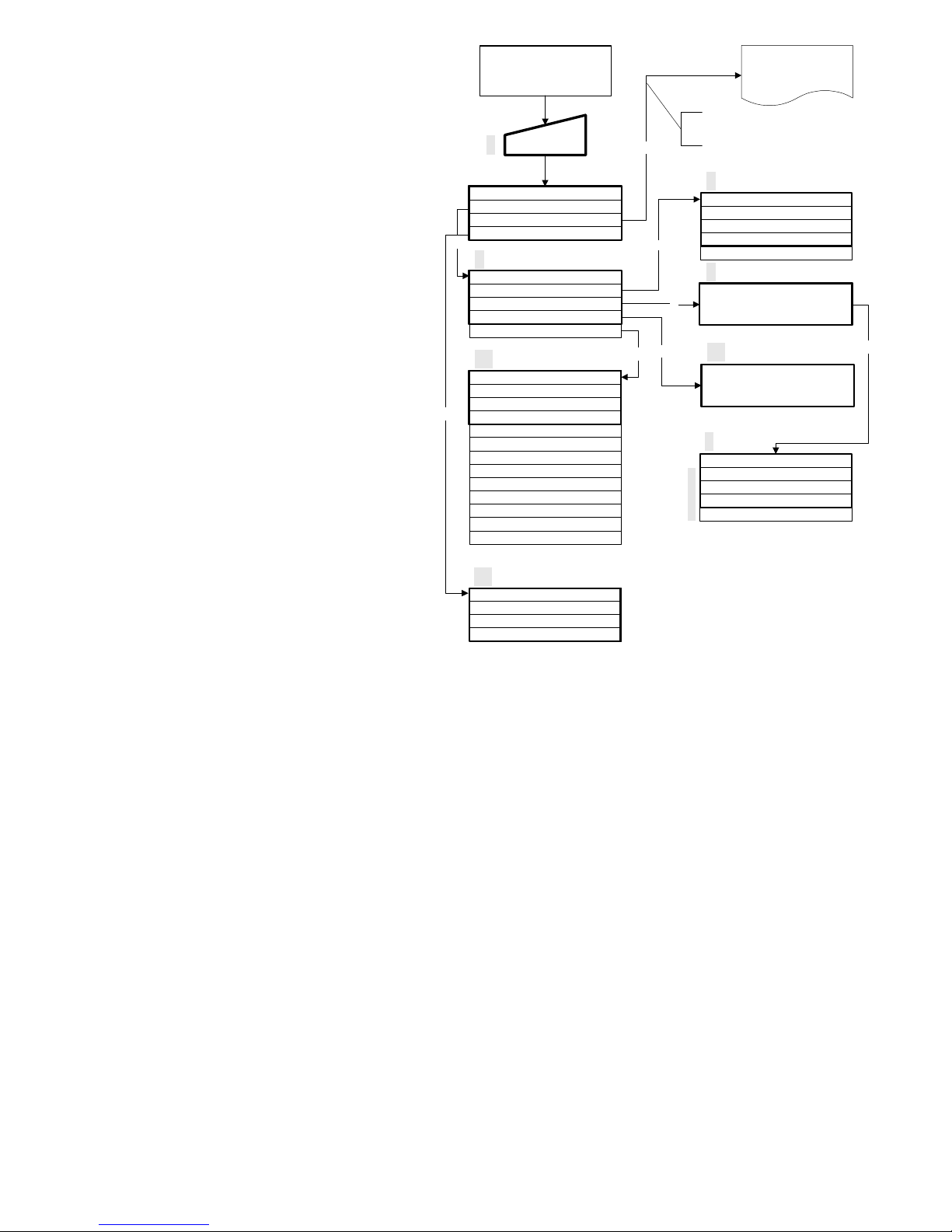
Program Menu "M"
Call (1)
The program menu "M" is selected by
pressing the "M" key
Except for the basic programming, all
functions can be called up without password
protection.
Service I (2)
Input reagent (3)
The new filling level has to be entered after
every refill or replacement of the reagent
bottle. As soon as the menu item for the
filling level "Reagent X filling (0 - 100%)" has
been selected by pressing "ENTER", the
value is preset to 100%. Confirm the
connection of a full bottle pressing "ENTER".
If only a partially filled bottle is connected,
enter the corresponding % value.
Manual operation (4)
After the information message (4) has been
confirmed by pressing ENTER, the desired
function can be selected using the arrow
keys and then activated by pressing
"ENTER".
These functions are used for monitoring the
operation and for commissioning.
L All manual functions can only be selected during an interval between two analyses. No analyses are carried out
during manual operation. All signal inputs and outputs are locked.
Flush (5)
Start the flushing of the sampling tube through the internal valve by pressing "ENTER". This function is terminated by
pressing the "ENTER" key again.
Flush chamber (6)
By pressing "ENTER", the measuring chamber is flushed once.
Drain chamber (7)
The outlet valve to drain the water from the measuring chamber is opened by pressing "ENTER".
This function is terminated by pressing the "ENTER" key again.
Fill chamber (8)
The measuring chamber is filled by pressing "ENTER".
Page 20
18 / 23
Confirm maintenance (10)
After maintenance has been carried out confirm this by pressing "ENTER", and leave this item by pressing "M". The
maintenance interval is started afresh.
L A maintenance request at the end of the maintenance interval must be confirmed in the M-menu. The message on
the display is deleted and the maintenance output is reset.
For information on which maintenance has to be carried out and in which time intervals refer to the section
maintenance on page 22.
Diagnosis (11)
The current status of the signal inputs and outputs can be called up from a list.
An active status is marked with a * (see menu structure).
Date/time of day (12)
Set the time of day and date by selecting the desired function using the arrow keys and activating them by pressing
"ENTER". Then press the "M" key again to store the setting and to return to the display mode.
Basic program
This menu item is only reached after entering the password!
Example for a password entry:
>BASIC PROGRAM 07:25
21.04.00 07:25
Password: ____ _ _ _ _
(5270)
After entering the password and confirming it by pressing "ENTER", it is possible to carry out the basic programming of
the unit and to select a number of service functions (e.g. calibration).
Program values
To call up the factory-set basic default setting, briefly hold down the "M" and "i" keys while switching the unit "ON".
Values and settings are described in the structure of the basic program on page 19.
The following program values can be entered and stored in the basic program:
Abbreviations: s = seconds
m = minutes
h = hours
d = days
l = litres
Page 21
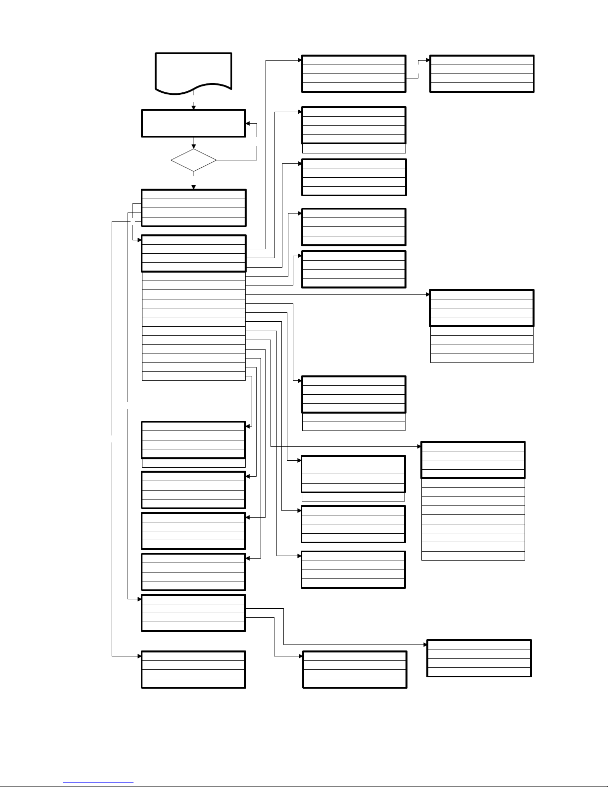
19 / 23
BASIC PROGRAM
st st
M E
PROGRAM VALUES
Service II
Customer service
SERVICE II
s stt
M E
Reset operating time
Maintenance interval
CUSTOMER SERVICE
stst
ME
GEBRUEDER HEYL
D-31135 HILDESHEIM
MODE OF OPERATION
Display of unit TH
Function Stop
ENTER
PROGRAM MENU
Testomat 2000 TH/Cl
BASIC PROGRAM
OPERATING TIME
stst
M E
000023h
Reset
TEL. 05121-7609-0
Function LV1
Hysteresis LV1
BASIC PROGRAM
st st
M E
DD.MM.YY HH.MM
Password MM.HH
ENTER
OK ?
YES
NO
E
ENTER
MODE OF OPERATION
sstt
M E
External (START)
Function LV2
Interfaces
Hysteresis LV2
FLUSH TIMES/INTERVAL
sstt
M E
INTERNAL FLUSH TIME 00s
Interval pause 1m
External flush time 00s
Volume interval
TIME-CONTROLLED *
Function AUX
Alarm/Message
Function IN1
FUNCTION LV1
s stt
M E
DURATION *
Time: 00m:10s
Impulse
FUNCTION LV2
s stt
M E
DURATION *
Time: 00m:10s
Impulse
Two-point only with 2 limit values and
1 measuring point
FUNCTION AUX
s stt
M E
Contact during analysis
CONTACT BEFORE ANALYSIS *
Contact after analysis
PROGRAM VALUES
s stt
M E
Water meter
INTERFACES
st st
M E
Type 0-20 mA
ALARM/MESSAGE
s stt
M E
REAGENT Cl LOW LEVEL A
Low water pressure A
Indicator TH low level A
Ff. optics A
Ff. dosing pump A
Ff. outlet to drain A
Mf. dirtiness M
power failure 24 V A
Mf. turbid M
Transfer error M
A = Alarm / M = Message / - = no action
Ff. = Function fault
Mf. = Measuring fault
TYPE OF WATER METER
s stt
M E
1 LITRE/IMPULSE
2.5 Litres/Impulse
Time: 00m 10s
Type RS232
Type 4-20 mA *
HYSTERESIS LV1
s stt
M E
Analysis (1,2,3) 1
HYSTERESIS LV2
s stt
M E
Analysis (1,2,3) 1
Flush times/interval
Limit values
Interval
Two point
Interval
Display of unit Cl
VOLUME INTERVAL
sstt
M E
000l
5 Litres/Impulse
10 Litres/Impulse
100 Litres/Impulse *
500 Litres/Impulse
1000 Litres/Impulse
FUNCTION IN1
st st
M E
NORMALLY CLOSED CONTACT
Normally open contact *
MAINTENANCE INTERV.
stst
M E
001d
FUNCTION STOP
st st
M E
NORMALLY OPEN CONTACT
Normally closed contact *
A/M/A/M
A/M
A/M
A/M
A/M/-
A/M/-
A/M
A/M/-
Meas. range exceeded M
A/M/-
Maint. int. exceeded M
A/M/-
A/M/-
E
LIMIT VALUES
s stt
M E
Limit val. Cl: 0.50 mg/l
LIMIT VAL. TH: 0.30°dH
DISPLAY OF UNIT TH
s stt
M E
Display in ppmCaCO3
Display in °f
DISPLAY IN °dH *
DISPLAY OF UNIT Cl
s stt
M E
Display in ppm
DISPLAY IN mg/l *
Display in mmol/l
Structure of the basic program
To call up the factory-set basic program, briefly hold down the "M" and "i" keys while switching the unit "ON". CAUTION, the
last set of programming will be erased!
Page 22
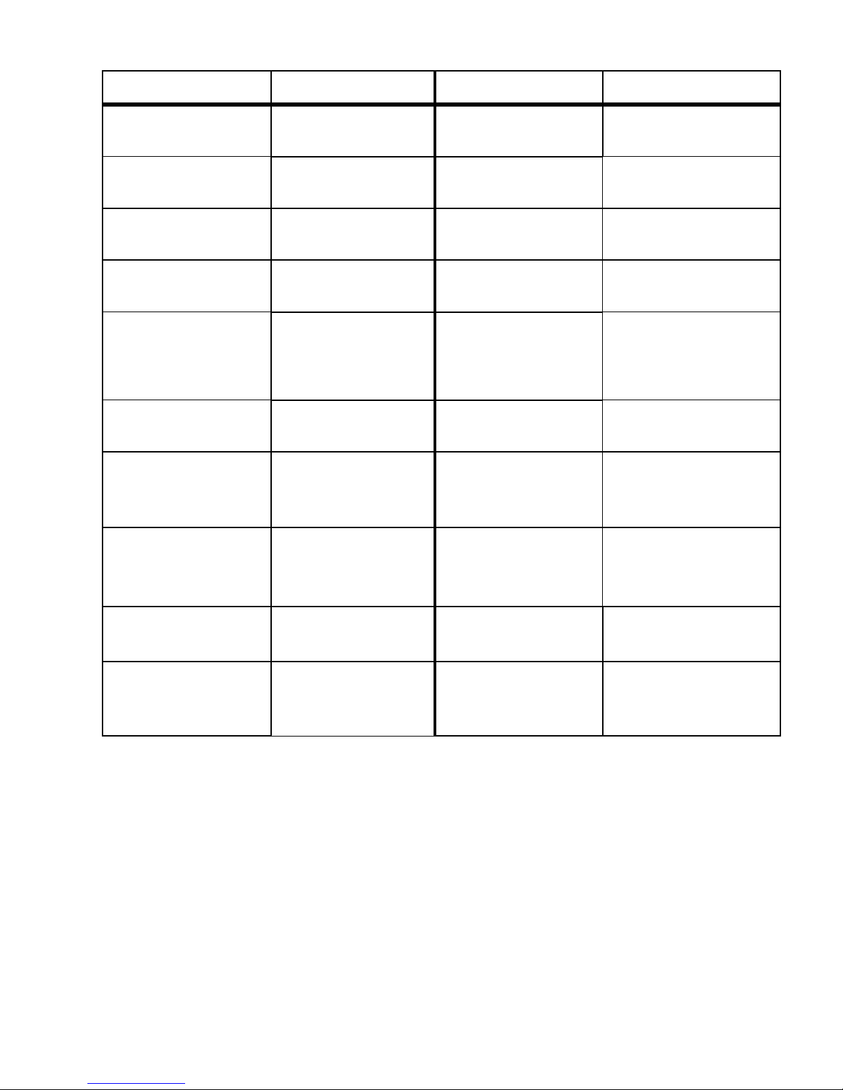
20 / 23
Error Messages / Trouble Shooting
Displayed Message
(flashes at selected display)
Unit result functions Possible causes Remedies
POWER FAILURE 24V
CANCEL WITH HORN-KEY
S After programming:
Continuous alarm or message
impulses
S Standby
• Internal power failure
of the 24 V supply
Replace fuse F4 or F8
(The control-lamp "Power" of the
dosing pump must light up)
Ff. DOSING PUMP
CANCEL WITH HORN-KEY
S After programming:
Continuous alarm or message
impulses
S Standby
• Dosing pump defective
• No dosing message from the
dosing pump
Replace dosing pump
Check cable to the dosing pump for
correct connection
Mf. TURBID
CANCEL WITH HORN-KEY
S After programming:
Continuous alarm or message
impulses or no message
S Continue measurements
• The water is turbid / dirty
MEASURING RANGE EXCEEDED
CANCEL WITH HORN-KEY
S After programming:
Continuous alarm or message
impulses or no message
S Continue measurements
• The measuring range is
exceeded
LOW WATER-PRESSURE
CANCEL WITH HORN-KEY
S After programming:
Continuous alarm or message
impulses
S Standby
• No water input although LED
"IN" lights up
• Inlet pressure too low
• Overflow reagent is not active
Check water inlet
Connector of the inlet valve oxidised
Clean filter strainer
Replace valve block
Extract pressure regulator valve
Replace fuse F6
Ff. OUTLET TO DRAIN
CANCEL WITH HORN-KEY
S After programming:
Continuous alarm or message
impulses
S Standby
• Water remains in the
measuring chamber although
LED "OUT" lights up
Check water outlet
Connector of the outlet valve
oxidised
Replace valve block
REAGENT LOW
CANCEL WITH HORN-KEY
S After programming:
Continuous alarm or message
impulses or no message
S LED and output
"maintenance" on
S Continue measurements
• Reagent quantity is below
minimum setting 50 ml (10 %),
Check reagent level, fill up if
necessary
(enter level: "M" º SERVICE)
Mf. DIRTINESS
CANCEL WITH HORN-KEY
S After programming:
Continuous alarm or message
impulses or no message
S LED and output
"maintenance" on
S Continue measurements
• Sight-glass windows dirty Clean sight-glass windows
Ff. OPTICS
CANCEL WITH HORN-KEY
S After programming:
Continuous alarm or message
impulses
S Standby
• Plug-in circuit board defective
• Error at the optic component
(Transmitter or Receiver
defective)
Replace plug-in circuit board
Replace measuring chamber
sealing rings
MAINTENANCE INTERVAL
EXCEEDED
XXX DAYS
CANCEL WITH HORN-KEY
S After programming:
Continuous alarm or message
impulses or no message
S LED and output
"maintenance" on
S Continue measurements
• Programmed maintenance date
reached or exceeded
Carry out maintenance and finally
cancel or confirm
Ff. = Function fault
Mf. = Measuring fault
Page 23
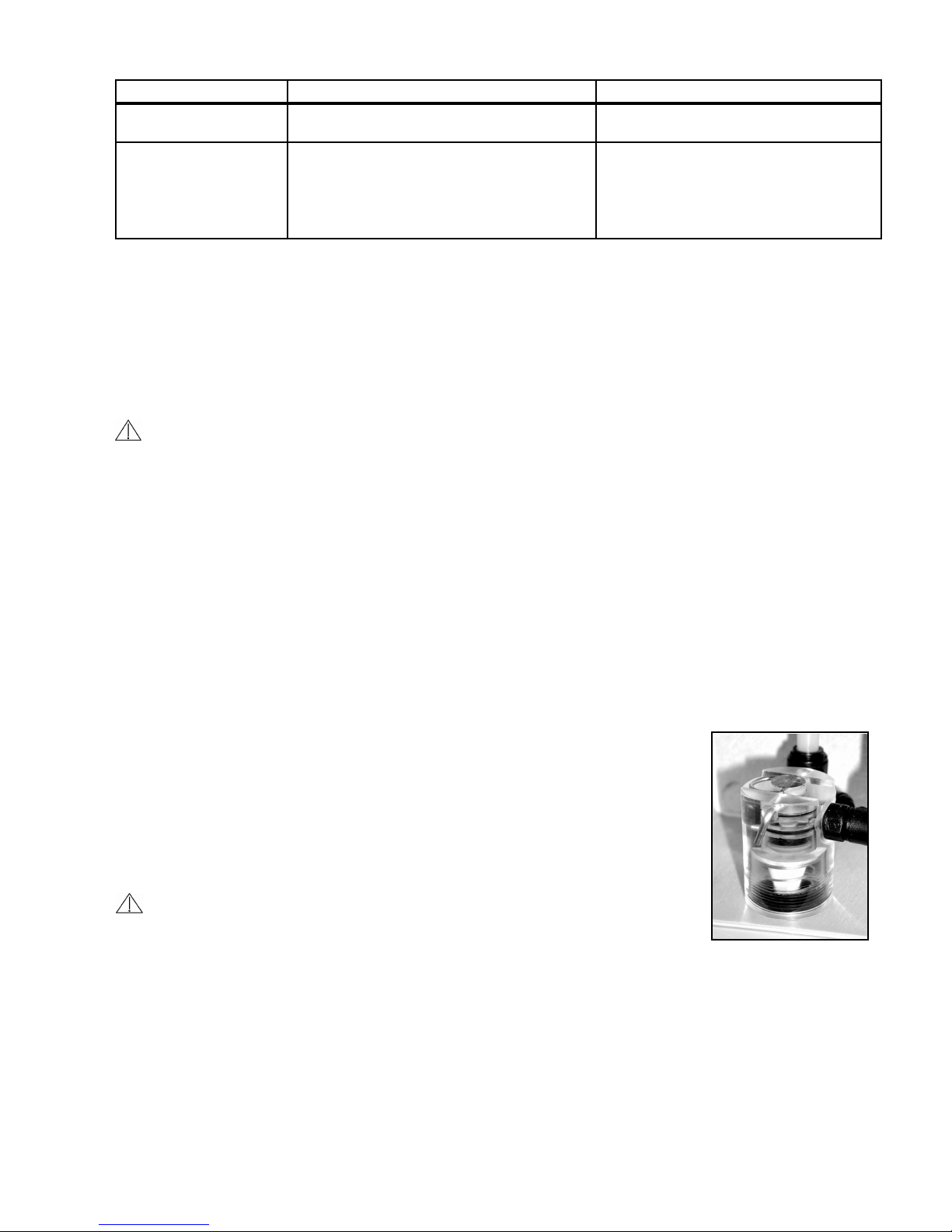
21 / 23
Further information
Fault Possible causes Remedies
Interface works incorrectly • Incorrect measuring value at the output or no
power supply
S Replace fuse F7
S Replace the plug-in circuit board
Although unit is switched
"ON"
No display
• Fuse F9, F5 or F2 (240 V: F1) defective
• Power switch defective
• Multi-pin strap cable at display circuit board or
base circuit board loose contact
• Fault on display circuit board or base circuit
board
S Replace fuses
S Replace power switch
S Check and reconnect multi-pin strap cable
S Replace display or base circuit board
Maintenance
Regular maintenance is necessary in order to ensure trouble-free operation of the unit!
Please carry out the maintenance work described in the following section if
S the programmed maintenance date has been reached (display "maintenance date exceeded")
S the unit displays the following error messages: "Mf. dirtiness" or "Reagent low level"
S the last maintenance was carried out more than 6 months ago
Never use organic solvents to clean the measuring chamber and other plastic parts!
Please observe the safety rules when handling cleaning agents!
Description of maintenance work
Cleaning the measuring chamber and the sight-glass windows
1. Switch the unit 'off' or press the "STANDBY" key (drain measuring chamber completely!).
2. Close the hand-operated valve on the branch line to the Testomat® 2000 THCl.
3. Unhook toggle type fastener, tip the measuring chamber upwards and extract.
4. Slacken both sight-glass window holders, extract and clean the sight-glass windows.
5. Remove coating from the sight-glass windows.
6. Clean the measuring chamber with 10% hydrochloric acid and then rinse well.
7. After cleaning, replace the sight-glass windows and secure these with the sight-glass windows holder
(do not forget the O-ring seals and check for correct seating in the recess).
8. Insert the measuring chamber by tilting it backwards until the slot engages with the rear guide bar and press down.
Finally secure the chamber with the toggle type fastener.
Cleaning the filter housing
1. Close the hand-operated valve on the branch line to the Testomat® 2000 THCl.
2. Undo the hose connections to the filter housing.
3. Unscrew inlet connection, remove sealing ring, spring and filter strainer and clean.
4. Extract the retaining pin and withdraw the flow regulator and finally remove the valve
body.
5. Clean filter housing with water or alcohol and reassemble.
Insert filter strainer point downwards!
6. Install the hose connections to the filter housing.
Water leakage from the seals can result in damage to parts of the unit.
TTip: Please check the unit for leaks before carrying out the first analysis
1. Switch the unit to STANDBY
2. Manually fill the measuring chamber
3. Manual reagent dosing (key "Manual")
4. Check the connections and seals for leaks
Notes on unit care
The surface of the unit has not been treated. Therefore, a contamination with reagent, oil or grease should be avoided.
Should the housing, however, be contaminated, please clean the surface with isopropanol (never use other solvents).
Page 24
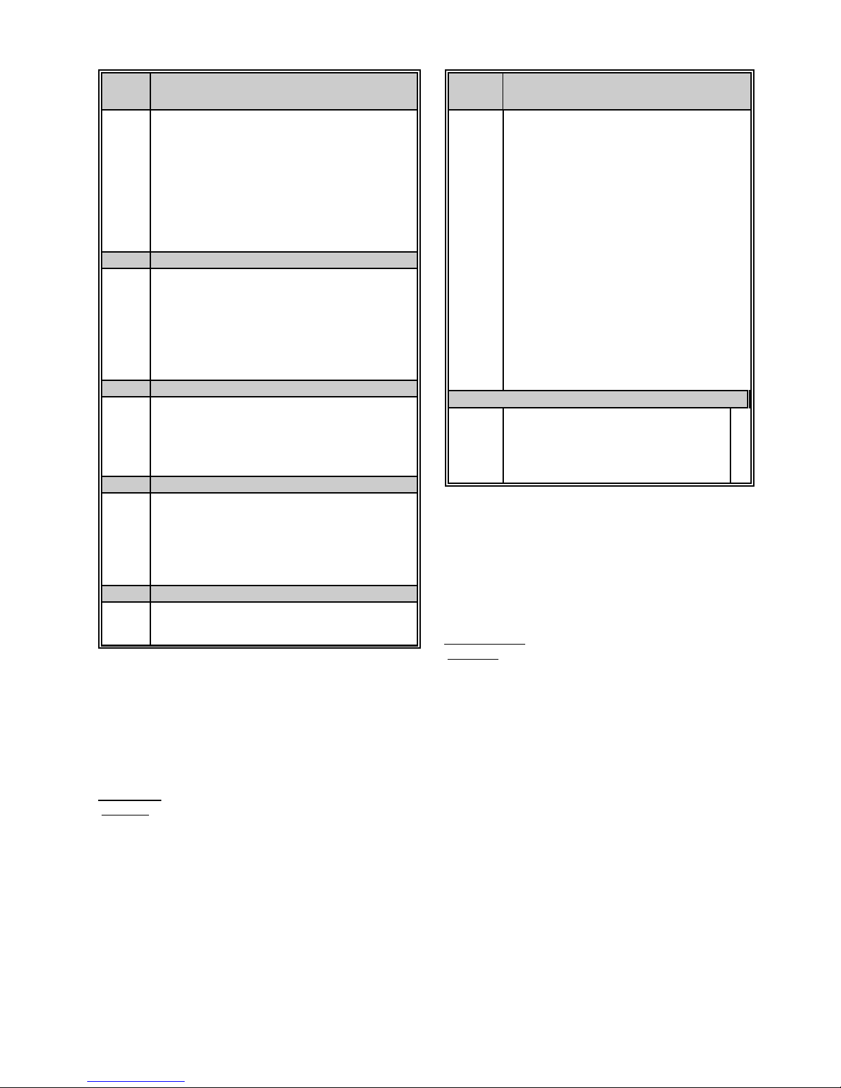
22 / 23
SPARE PARTS LIST Testomat
®
2000 THCl
Item
No.
Pressure regulator
040120 Regulator / filter housing
040129 Regulator plug T2000, complete
011225 Flow regulator valve (1 - 8 bar)
011230 Retaining pin for regulator plug
011217 Inlet filter
011218 Spring for inlet filter
040121 Inlet connector
040153 Plug in connector - G 1/4" -6
011209 Holding screw M3 x 42
Measuring chamber
040173 Sight-glass window 30 x 3 with seal
040170 Sight-glass window 30 x 3
040176 Sight-glass retaining disc
033253 Screw spindle M3 x 40
040032 Latch fastener TL 800-7-1
011203 Plastic plug
040022 Measuring chamber complete T2000
Holding block for measuring chamber
0400xx Holding block DUO complete (without measuring
040050 Magnetic stirrer
040186 Plug connector
040018 Solenoid valve, 2/2-Way
040181 Rear guide bar for measuring chamber 5 x 60
Dosing pump DOSIClip®
040001 Jet pump complete
040011 Suction capillary complete
040016 Pressure capillary complete
037232 Base circuit board TI, complete
034668 Magnet 24 VDC
032046 Plastic cover CNH 45 N
Bottle connection / Suction tube
040131 Screwed cap with bottle insert T2000
040130 Screwed cap GL32 - only
040132 Bottle insert for screwed cap
Item
No.
Electrical components
031582 Fuse M4A
037236 Base circuit board T2000 complete 230V
040092 Control circuit board T2000 complete
040091 Plug-in circuit board Transmitter / Receiver T2000
040190 Cable sleeve 5 - 7
040191 Cable sleeve 7 - 10
040197 Mains on / off switch T2000
040198 Cover for Mains on / off switch
031713 Multi-pin strap cable 10 pol. with EMI filter clamp
040096 Multi-pin strap cable 26 pol. with EMI filter clamp
040060 Cable loom 2V complete (for valves)
040064 Cable loom 4P complete (for four dosing pumps)
040200 Cable loom for mains on/off switch complete
031596 Fuse T0.08A
031585 Fuse T0.315A
031595 Fuse T0.1A
031622 Fuse T0.16A
031592 Fuse T1.0A
Spare parts requirement for 2 - 3 years of operation
040173 Sight-glass window 30 x 3 with seal 2
011217 Inlet filter 1
040124 Gasket set T2000 ( after maintenance ) X
031585 FuseT0.315A 1
031592 Fuse T1.0A 1
X* X*Accurate operation of the TESTOMAT
®
2000 THCl
can only be assured with regular maintenance and
replacements of seals / gaskets (see chapter on
maintenance).
Accessories:
Item no..
040123 Optional adapter for water inlet T2000
(Quick-acting plug and -coupling)
270305 Interface (plug-in card) SK 910
270310 Plug-in card RS910 (Interface RS232)
270335 Maintenance case T2000
Reagents:
Item no.
156230 CL2250A Chlorine 0 - 2.5 mg/l (ppm), Reagent A, 500ml
156231 CL2250B Chlorine 0 - 2.5 mg/l (ppm), Reagent B, 500ml
156232 CL2250C Chlorine 0 - 2.5 mg/l (ppm), Reagent C, 500ml
152025 TH2025 Water hardness 0.25 - 2.5 °dH, 500ml
Page 25
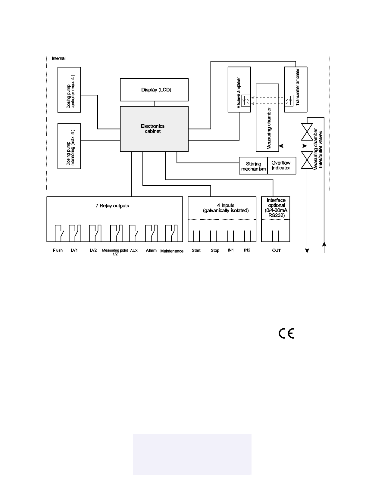
23 / 23
Technical appendix
Block diagram Testomat® 2000 THCl
Technical data
Power supply: 230 V or 24 V ± 10 %, 50 - 60 Hz, fuse M4A
Unit protection: 230 V: T0.1A
24 V: T1.0A
The unit is power failure protected
Power consumption: max. 30VA
Degree of protection: IP 65
Protection class: I
Conformity: EN50081-1, EN50082-2, EN 61010-1
Ambient temperature: 10 - 45 °C
Contact rating of the relay outputs: 4 A resistive load, fuse M4A
Measuring range: see page 1
Interface: 0/4 - 20 mA, max. load 500 Ù (optional)
Water supply: 0.1 - 8 bar = 104 - 8 x 10⁵ Pa
Water temperature: max. 40 °C
Dimensions (W x H x D): 380 x 480 x 280 mm
Weight: approx. 10.5 kg
We reserve the right to make technical changes without notice in the interest of constantly improving our
products!
Art.-Nr. 49546 Kf T2000_THCL_GB030523.wpd
Lenntech
info@lenntech.com Tel. +31-152-610-900
www.lenntech.com Fax. +31-152-616-289
info@lenntech.com Tel. +31-152-610-900
www.lenntech.com Fax. +31-152-616-289
Lenntech
 Loading...