

Lenntech Testomat 2000, Testomat 2000 Polymer, Testomat 2000 PO4 Operating Instructions Manual
Page 1

Testomat 2000®
Online analysis unit
with cleaning function for water
hardness, carbonate hardness,
p-value or minus m-value
Operating Instructions
Page 2

Content
2
Content
Content ................................................................................................. 2
Important safety information ............................................................. 4
Intended use ......................................................................................... 4
Qualification of the staff ........................................................................ 4
Warning notices in these instructions ................................................... 5
Further documents ................................................................................ 5
Pay particular attention to ..................................................................... 5
General instructions .............................................................................. 5
Installation ............................................................................................. 6
Operation .............................................................................................. 6
Downtimes ............................................................................................ 6
Cleaning ................................................................................................ 6
De-installation ....................................................................................... 6
Disposal ................................................................................................ 6
Scope of delivery ................................................................................ 7
Performance specifications ............................................................... 7
Indicators for Testomat 2000® instruments ........................................... 8
Application instructions ..................................................................... 9
Installation ......................................................................................... 10
Operating Testomat 2000® in the pressure range of 0.3 to 1 bar ....... 10
Installing Testomat 2000® ................................................................... 10
Connecting the water inlet and outlet ................................................. 11
Water inlet ........................................................................................... 11
Water outlet ......................................................................................... 11
Connecting the power supply and devices ......................................... 12
Block diagram Testomat 2000® .......................................................... 12
Internal design Testomat 2000® .......................................................... 13
Connecting the mains voltage............................................................. 14
Connecting the plant components ...................................................... 15
Connecting the inputs and outputs ..................................................... 16
Commissioning ................................................................................. 17
Inserting the indicator bottle ................................................................ 17
Extracting the indicator ....................................................................... 17
Opening the water inlet ....................................................................... 17
Instrument settings and data input ...................................................... 18
Functions of the operating and display elements ......................... 18
Switching Testomat 2000® on/off ........................................................ 18
Display functions ................................................................................. 19
Operating elements and function keys ............................................... 20
Operating system ................................................................................ 21
Password protection and basic program ....................................... 22
Entering basic program data ............................................................... 22
Selecting the indicator and the bottle size .......................................... 22
Selecting the operating mode ............................................................. 23
Selecting the display unit .................................................................... 25
Entering further basic program data .............................................. 26
Internal flushing ................................................................................... 26
External flushing ................................................................................. 26
Interval pause ..................................................................................... 27
Page 3

Content
3
Limit value monitoring ......................................................................... 27
Hysteresis ........................................................................................... 28
Lock out ............................................................................................... 28
Switch functions of the limit value outputs LV1 and LV2 .................... 29
Switch function 0, duration .................................................................. 29
Switch function 1, impulse .................................................................. 29
Switch function 2, interval ................................................................... 29
Switch function 3, two-point ................................................................ 29
Function IN1 ........................................................................................ 30
Water meter ........................................................................................ 30
Plant control ........................................................................................ 30
BOB operation (operation without permanent supervision) ................ 31
Alarm/Message ................................................................................... 32
Function AUX ...................................................................................... 32
Cleaning function ................................................................................ 33
Service II ............................................................................................. 34
Reset operating time ........................................................................... 34
Maintenance interval ........................................................................... 34
Water quantity RESET
........................................................................ 34
Plant control RESET ........................................................................... 34
Description of the signal inputs/outputs ........................................ 35
Interfaces (optional) ............................................................................ 36
Installing the interface cards SK910/RS910 ....................................... 36
Monitoring a measuring point.............................................................. 37
Monitoring of two measuring points .................................................... 37
Calculation of output currents ............................................................. 38
Serial interface RS232 ........................................................................ 38
SD Card Data logger ........................................................................... 39
Description of the relay outputs ...................................................... 39
Flushing (external flush valve) ............................................................ 39
LV1 and LV2 limit value outputs ......................................................... 39
Measuring points 1 or 2 (measuring point switch-over) ...................... 40
AUX (programmable function output) ................................................. 40
Alarm (fault message output) .............................................................. 41
Maintenance (output for maintenance message) .............................. 41
Information menu "i" ........................................................................ 42
Program menu "M" ........................................................................... 43
Structure of the basic program............................................................ 45
Error messages/Troubleshooting ................................................... 46
Further information .............................................................................. 47
Maintenance ...................................................................................... 48
Description of maintenance work ........................................................ 48
Service instructions ............................................................................. 49
Testomat 2000® spare parts and accessories ................................ 50
Accessories ......................................................................................... 51
Technical data ................................................................................... 52
Conformity Declaration ....................................................................... 53
Check List Testomat 2000® ................................................................ 54
Product overview Testomat 2000®-Instruments ............................ 56
Page 4

Important safety information
4
Important safety information
Please read these operating instructions carefully and completely
prior to working with the instrument.
Ensure that these operating instructions are always available for all
users.
These operating instructions must always be passed on to the new
owner should Testomat 2000® change hands.
Always adhere to hazard warnings and safety information when
using reagents, chemicals and cleaning agents. Please adhere to
the respective safety data sheet! Download the safety data sheets
for the supplied reagents at http://www.heyl.de .
Intended use
The Testomat 2000® is used for the automatic measuring and
monitoring of the residual / total hardness (water hardness), the
carbonate hardness, the minus m-value and the p-value. The
parameter to be measured and the respective measuring range are
determined by the choice of the reagent and by the corresponding
user program.
Testomat 2000® self clean is a special version of Testomat 2000®
with an additional pump for dosing a cleaning agent after analysis.
This, e.g., helps to prevent possible soiling of the measuring chamber
and outlet hose.
Always adhere to the performance limits stated in the section
entitled “Technical data”.
Always observe the application areas/application limits of the
indicators and the requirements of the medium being measured.
To ensure correct and intended usage, always read and understand
these instructions, especially the section entitled “Important safety
information”, prior to use.
The instrument is not used as intended if
it is used in areas not specified in these instructions.
it is used in areas which do not correspond to the ones described
in these instructions.
Qualification of the staff
Assembly and commissioning require fundamental electrical and
process engineering knowledge as well as knowledge of the
respective technical terms. Assembly and commissioning should
therefore only be carried out by a specialist or by an authorised
individual supervised by a specialist.
A specialist is someone who due to his/her technical training, knowhow and experience as well as knowledge of relevant regulations can
assess assigned tasks, recognise potential hazards and ensure
appropriate safety measures. A specialist should always adhere to
the relevant technical regulations.
Page 5

Important safety information
5
Warning notices in these instructions
The warning notices in these instructions warn the user about
potential dangers to individuals and property resulting from incorrect
handling of the instrument. The warning notices are structured as
follows:
Description of the type or source of danger
Description of the consequences resulting from non-observance
Preventive measures. Always adhere to these preventive
measures.
“DANGER” indicates an immediate hazardous situation which, if not
avoided, will result in death or serious injury.
“WARNING” indicates a potentially hazardous situation which, if not
avoided, could result in death or serious injury.
“CAUTION” indicates a potentially hazardous situation which, if not
avoided, could result in minor or moderate injuries or property
damage.
“NOTE” indicates important information. If this information is not
observed, it may result in an undesirable result or state.
Further documents
Testomat 2000® is a plant component. Therefore, always observe the
maintenance manual of Testomat 2000® / Testomat ECO® and the
documentation of the plant manufacturer.
Pay particular attention to
General instructions
Adhere to health and safety regulations, electrical equipment
safety regulations, and environmental protection regulations valid
in the country of use and at the installation site.
Adhere to national and local regulations during installation and
commissioning.
Always protect the instrument against moisture and humidity. It
should never come into contact with condensation or splash water.
Do not carry out any changes or modifications at the instrument
which are not described in these instructions;
failure to adhere to
these instructions will negatively affect any warranty claims that
you make thereafter.
SIGNAL WORD!
WARNING
!
DANGER
!
WARNING
!
CAUTION
!
NOTE
Page 6

Important safety information
6
Installation
Always completely disconnect the relevant plant part before
installing the instrument or connecting/disconnecting it to/from the
power supply. Secure the plant against reconnection.
Only connect the instrument to the mains voltage specified on the
rating plate.
Always observe technical data and ambient parameters.
Testomat 2000® requires an interference free and stable power
supply. If necessary, use a mains filter to protect Testomat 2000
®
against interference voltages caused, e.g., by solenoid valves or
large motors. Never lay connecting cables parallel to power cables.
Operation
Ensure that the maximum electrical load capacity of the relay
outputs is never exceeded.
Immediately switch off Testomat 2000® and contact service staff if
malfunctioning occurs. The warranty will be void if you tamper with
or attempt to repair Testomat 2000®. Repairs must be carried out
by authorised service staff.
Downtimes
If the Testomat 2000® is switched off for a longer period of time,
such as over the weekend, you need to vent the dosing pump
pipes once you have switched it back on. To do so, proceed as
described under “Extracting the indicator” on page 17.
Cleaning
Only use a dry, lint-free cloth for cleaning.
De-installation
Prior to de-installing a defective instrument, always write down a
description of the error (failure effect). It is only possible to repair a
defective instrument (irrespective of the warranty period) if it has
been de-installed and returned to us with a description of the error.
Disposal
Dispose of the instrument in accordance with national regulations.
WARNING
!
NOTE
Page 7

Scope of delivery
7
Scope of delivery
1x Testomat 2000® self clean
1x plastic bag containing a screw cap with a hole and an insert for the
screw cap of the indicator bottle
1x operating instructions
Performance specifications
Testomat 2000® is used for the automatic determination and
monitoring of residual total hardness (water hardness), residual
carbonate hardness, as well as the minus m-value and the p-value in
water. The measurement parameters and the measuring range are
determined by the indicator selection and according to the user
programming.
Simple, menu-driven operating and programming via a plain
text display
Determinable measuring of residual hardness, total
hardness, carbonate hardness, minus m-value, p-value via
indicator selection
Freely selectable hardness unit in °dH, °f, ppm CaCO3,
mmol/l
High measuring accuracy provided by a precise piston-
dosing pump
Analysis initiation:
- Automatic interval operation
(Interval pause justable from 0 to 99 minutes)
- External control
- Dynamic start (Exhaustion dependent)
- Volume controlled (water meter)
Two independent limit values with hysteresis (1, 2 or 3 bad
analyses) and adjustable switch functions
Monitoring of two measuring points (change-over via external
solenoid valves)
Internal error documentation
Programmable service address
Programmable maintenance interval for a maintenance
request
Extended operating periods due to 500 ml indicator storage
bottle
optional
Interface (0/4-20 mA or 0/2-10 V) or
Interface RS 232 for a log printer
SD Card data logger
Page 8

Performance specifications
8
Indicators for Testomat 2000® instruments
Parameter/Indicator type
Water hardness
TH 2005
TH 2025
TH 2100
TH 2250
Unit
°dH
(resolution)
0.05 – 0.50
(0.01)
0.25 – 2.50
(0.05)
1.0 – 10.0
(0.2)
2.5 – 25.0
(0.5)
°f
(resolution)
0.09 – 0.89
(0.02)
0.45 – 4.48
(0.1)
1.8 – 17.9
(0.4)
4.5 – 44.8
(1.0)
ppm
CaCO
3
(resolution)
0.89 – 8.93
(0.2)
4.5 – 44.8
(0.9)
18 - 179
(3.8)
45 - 448
(10)
mmol/l
(resolution)
0.01 – 0.09
(0.002)
0.04 – 0.45
(0.01)
0.18 – 1.79
(0.04)
0.45 – 4.48
(0.1)
Parameter/Indicator type
Carbonate hardness
minus m-
value
p-value
TC 2050
TC 2100
TM 2005
TP 2100
Unit
°dH
(resolution)
0.5 – 5.0
(0.5)
1.0 – 20.0
(1.0)
-
-
°f
(resolution)
0.90 – 8.96
(0.9)
1.8 – 35.8
(1.79)
-
-
ppm
CaCO
3
(resolution)
8.9 - 89.5
(8.9)
18 - 358
(18)
-
-
mmol/l
(resolution)
0.18 – 1.79
(0.18)
0.36 – 7.16
(0.36)
0.05 – 0.50
(0.01)
1 - 15
(1)
Display, if measuring value is outside of range (for example TH2005):
At falling below: < 0,05°dH
At exceeding: > 0,50°dH
Page 9

Application instructions
9
Application instructions
Wait at least 5 seconds before switching the instrument on and
then off again at the main switch.
In order for Testomat 2000® to operate reliably, use Heyl
Testomat 2000® indicators. Operate in the pH-range 4 – 10.5,
when determining the total hardness!
With Testomat® instruments for water hardness monitoring, larger
quantities of heavy metal ions in the softened water might
influence the color reaction, especially iron above 0.5 mg/I,
copper above 0.1 mg/I and aluminum above 0.1 mg/l (brownishred color display).
If the measuring water contains more than 20 mg/I CO2 (carbonic
acid), incorrect evaluations cannot be excluded.
The concentration of influencing contents can be determined by
using our colorimetric TESTOVAL® test kit.
Careful handling of the instrument increases both its operational
reliability and service life! Therefore, carry out a visual inspection
at regular intervals as described below:
- Has the use-by-date of the indicator expired?
- Are the hose connections of the dosing pump free of leaks?
- Is there any air inside the dosing hoses?
- Are all the water connections free of leaks?
- Are the doors of the instrument closed properly?
- Is the instrument heavily soiled?
- Are the measuring chamber and the drain duct/drain hose
clean?
Trouble-free operation is only possible when maintenance is
carried out on a regular basis! For more information, please refer
to the section entitled “Maintenance” and the "Maintenance
manual of Testomat 2000®/Testomat ECO®".
If problems occur, please refer to the section entitled "Error
messages/Troubleshooting".
No opening of the measuring chamber holder!
Do not open the measuring chamber holder. You cannot carry out
any repairs in this area, but damage the device. If you open the
measuring chamber holder, your warranty will expire.
CAUTION
!
Page 10

Installation
10
Installation
Risks resulting from incorrect installation!
Install Testomat 2000® at a location where it is protected against
dripping or splash water, dust and aggressive substances – e.g. in
a switch cabinet or on a suitable wall.
Information for trouble-free operation
Install Testomat 2000® vertically and without mechanical stress.
Install Testomat 2000® at a vibration-free site.
Operating Testomat 2000® in the pressure
range of 0.3 to 1 bar
Prior to installation, please check whether lower operating pressure is
required. The instrument is factory set for the operating range of 1 to
8 bar. Remove the flow controller valve body to operate the
instrument in the operating range of 0.3 to 1 bar (e.g. when using an
aerator type R). This involves removing the retaining pin from the
controller/filter receiver . Subsequently use the metal bracket to
remove the controller plug from the borehole. Then remove the
flow controller valve body and reinsert the controller plug and the
retaining pin.
Installing Testomat 2000®
Select an installation site where the water inlet hose can be kept as
short as possible (max. 5 m).
Please leave sufficient space on the left-hand side of the
instrument to open the door.
Drill the mounting holes as shown in the drawing on the left.
Use three screws to attach the instrument at a suitable position in
the switch cabinet or on a wall.
Remove for
pressure range
0.3 to 1 bar
WARNING
!
NOTE
Page 11

Installation
11
Connecting the water inlet and outlet
Information for trouble-free operation
The water pressure must be between 0.3 bar and 8 bar
Avoid strong pressure fluctuations
The measuring water temperature must be between 10 °C and
40 °C
For temperatures above 40 °C, the KCN type cooler should be
installed in the branch line of Testomat 2000®.
Water inlet
The measuring water is taken from the main water line of the water
treatment plant and fed to the inlet connection of Testomat 2000®.
The instrument is equipped with a plug connector for plastic hoses
6/4 x 1 (external diameter 6 mm/ internal diameter 4 mm, wall
thickness 1 mm) as standard.
Install the connection for the branch line of Testomat 2000®
directly at the main water line directly after the water treatment
plant
It is important that the branch line connection is laid vertically
upwards in order to prevent dirt particles from entering the
instrument from the main water line.
Install a manually operated shut-off valve in the branch to
Testomat 2000®.
Use an opaque plastic hose 6/4 x 1 (max. length 5 m) for the water
inlet .
Flush the inlet to remove any dirt particles.
When operating within a pressure range of 0.3 to 1 bar or with a
supply via a booster pump, please remove the valve body from the
controller and the filter housing. The pump should have a feeding
capacity of between 25 and 35 litres/hour and be resistant to the
medium being measured.
When using a cooler
The hot water can cause burns and damage wetted parts of
Testomat 2000®.
Water outlet
The feed water flows through the measuring chamber to the drain via
the outlet hose.
Connect the outlet connection of Testomat 2000® to an opaque
outlet hose (internal diameter 14 mm).
Lay this hose without backwater development and any syphoning
effect, e.g. via an open funnel, to the drain.
NO !!
"Sagging"
causes
backwater!
CAUTION
!
NOTE
Page 12

Installation
12
Connecting the power supply and devices
Risk of electric shocks during installation!
If the power supply is not disconnected prior to installation, it may
result in personal injuries, destruction of the product or damage to
plant parts.
Always disconnect the relevant plant parts before installing
Testomat 2000®.
Only use tested cables with sufficient cross-sections for the
connections.
Risk of damages caused by electromagnetic fields!
If Testomat 2000® or the connecting cables are installed parallel to
power cables or in close proximity to electromagnetic fields, the
instrument may be damaged or measurements incorrect.
Ensure that connecting cables are as short as possible.
Always install connecting cables and power cables separately.
Connect the instrument to the protective earth conductor (for
230/115 VAC).
Protect Testomat 2000® against interference voltages – e.g. by
using a mains filter.
Shield the instrument against strong electromagnetic fields.
Block diagram Testomat 2000
®
Drawn relay positions: Instrument de-energised
WARNING
!
NOTE
Page 13

Installation
13
Internal design Testomat 2000®
Terminal strip for inputs Start, Stop, IN1, IN2, and output OUT
Mains switch
Terminal strip for power input and power output
Terminal strip for relay outputs
Dosing pumps
Water connections, inlet and outlet
Controller / Filter receiver
Measuring chamber
*
*
Page 14

Installation
14
Connecting the mains voltage
Only connect the instrument to the specified mains voltage. Refer to
the rating plate for the appropriate mains voltage. Connect the cables
as follows:
Loosen both fastening screws and open the upper door. The
terminal box is now accessible.
Pierce the required rubber cable glands with a screwdriver and
insert the cable through the bush into the terminal box (1)
Subsequently pull back the cable until the bush has been turned
over (2).
Connect the power supply to terminals PE, N, L or for 24 V
instruments to terminals U, V.
Connect the conductor to the terminal block as shown on the left
.
Ensure that the leads are held securely in the terminals.
Proceed as shown in figure to loosen the connection.
Terminal
Type
Function
Comment
PE
IN
Protective earth conductor (5x)
Only for
mains
115/230 V !
N (U)
L (V)
IN
Mains, N= neutral conductor (U=24 V)
Mains, L= phase (V=24 V)
Mains input
24 V / 115 V /
230 V
n
l
OUT
Neutral, switched (8x)
Phase, switched (8x)
Mains for
consumers,
max. 4 A
Insert the conductor with
ferrule or the solid conductor
into the round input.
1. Insert a screwdriver
into the square opening
without force in order
to open the terminal.
2. Once the terminal has been
opened, remove the conductor.
Page 15

Installation
15
Connecting the plant components
Connect the plant components to the output terminals of relays 1
to 19 (e.g. valves).
If the plant components require mains voltage, connect the
switched mains voltage (l) to the common contact of the
respective relay (see the connection example for 230 VAC on the
left).
Connect the neutral conductor of the plant component to one of the
terminals (n).
For components with a protective earth conductor connection,
connect it to the PE connection.
Ensure that the leads are held securely in the terminals.
(Drawn relay positions: Instrument de-energised)
No.
Terminal
Type
Function
Comment
1
2
Flush
OUT
External flush valve
Isolated relay output, max.
240 VAC, 4 A
3
4 5 LV1
OUT
Limit value output 1 – N/C
Limit value output 1 – N/O
Limit value output 1 - Common
Isolated relay output, max,
max. 240 VAC, 4 A
6
7 8 LV2
OUT
Limit value output 2 – N/C
Limit value output 2 – N/O
Limit value output 2 - Common
Isolated relay output, max.
240 VAC, 4 A
9
10
11
M. point.
1/2
OUT
Measuring point 1 – N/C
Measuring point 2 – N/O
M. point switch-over - Common
Isolated relay output, max.
240 VAC, 4 A
12
13
AUX
OUT
Universal output
Isolated relay output, max.
240 VAC, 4 A
14
15
16
Alarm
OUT
Fault message output – N/C
Fault message output – N/O
Fault message output - Common
Isolated relay output, max.
240 VAC, 4 A
17
18
19
Maintenan
ce
OUT
Maintenance message – N/C
Maintenance message – N/O
Maintenance message - Common
Isolated relay output, max.
240 VAC, 4 A
Connection example
Limit value contact LV 1
switches mains voltage
n
l
3 4 5
e.g.
solenoid
valve
PE
Page 16

Installation
16
Connecting the inputs and outputs
Testomat 2000® has the following connections for control and
monitoring functions.
Do not connect an external voltage to these connections!
Ensure that the leads are held securely in the terminals.
Use the two fastening screws to close the upper door once
installation has been completed.
For more information, please refer to the section entitled "Description
of the signal inputs/outputs".
No.
Terminal
Type
Function
Comment
20
21
Start
IN
External analysis start
common earth for inputs
Only connect isolated normally
open contact!
22
23
Stop
IN
External analysis stop
common earth for inputs
Only connect isolated normally
closed/open contact!
24
25
IN1
IN
Universal input 1
common earth for inputs
Only connect isolated normally
closed/open contact!
26
27
IN2
IN
Universal input 2 (water meter)
common earth for inputs
Only connect isolated normally
open contact!
┴
28
29
OUT
OUT
OUT
OUT
OUT
OUT
IN
RS 910: Earth
SK910:
(+)
UK910:
(+)
RS910:
(TxD)
SK910:
(-)
UK910:
(-)
RS232:
(RxD)
RS232 interface for printer
Galvanically separated current
interface 0/4 - 20mA
Galvanically separated voltage
interface 0/2 – 10V
RS232 interface for printer
Galvanically separated current
interface 0/4 - 20mA
Galvanically separated voltage
interface 0/2 – 10V
RS232 interface for printer
Page 17

Commissioning
17
Commissioning
Handling of reagents/indicators
Adhere to the respective safety data sheet!
Trouble-free operation of Testomat 2000® is only guaranteed when
using Heyl Testomat 2000
®
indicators!
Inserting the indicator bottle
Open the lower housing door by pulling on the right-hand side.
Remove the cap from the indicator bottle.
Remove the plastic bag from inside the lower housing door. The
plastic bag contains the screw cap with hole and the insert
for the screw cap.
Connect the parts as shown on the left.
Screw the hose connector of the intake hose hand-tight into
the insert .
Place the insert with the screwed-in intake hose into the indicator
bottle.
Now screw the screw cap with hole hand-tight onto the
indicator bottle.
Extracting the indicator
Switch the instrument on and press the "STANDBY" key.
During operation, the pump (DOSIClip) automatically extracts
indicator.
To ensure that indicator is available for the initial analyses, the
intake hose and the transport hose must be filled with
indicator from the pump up to the measuring chamber.
Press the "manual" key several times until the intake hose
and the transport hose are filled with indicator up to the
measuring chamber (always switch on the instrument at the mains
switch first!)
If necessary, manually tighten the hose connectors of the intake
and transport hose slightly in case of bubble formation.
Opening the water inlet
Open the lower housing cover.
Slowly open the manually operated shut-off valve to prevent the
measuring chamber overflowing. The flow regulator requires a few
seconds to function correctly.
Make sure that the water conducting parts are not leaky.
CAUTION
!
Indicator
Page 18

Functions of the operating and display elements
18
If water sprays from the tube of the measuring chamber ,
reduce the amount of inlet water via the manually operated shut-off
valve. It should take 2 to 6 seconds to fill the measuring chamber!
Instrument settings and data input
Please read the following information before carrying out settings
and entering data for operating the instrument.
Functions of the operating and
display elements
The Testomat 2000® display shows operating statuses and measured
values. The input keys for programming (cursor block) and the
function keys are located underneath the display.
Switching Testomat 2000® on/off
(1) Mains switch
Use this switch to switch the instrument on or off.
(2) Instrument fuse (inside the instrument)
This fuse protects Testomat 2000® and the outputs against
overloads and short circuits.
(1)
(2)
Page 19
Functions of the operating and display elements
19
2a
2b
Inlet
valve
Analysis
running
Outlet
valve
Dosing
message
BOBmode
active
Analysis
stop
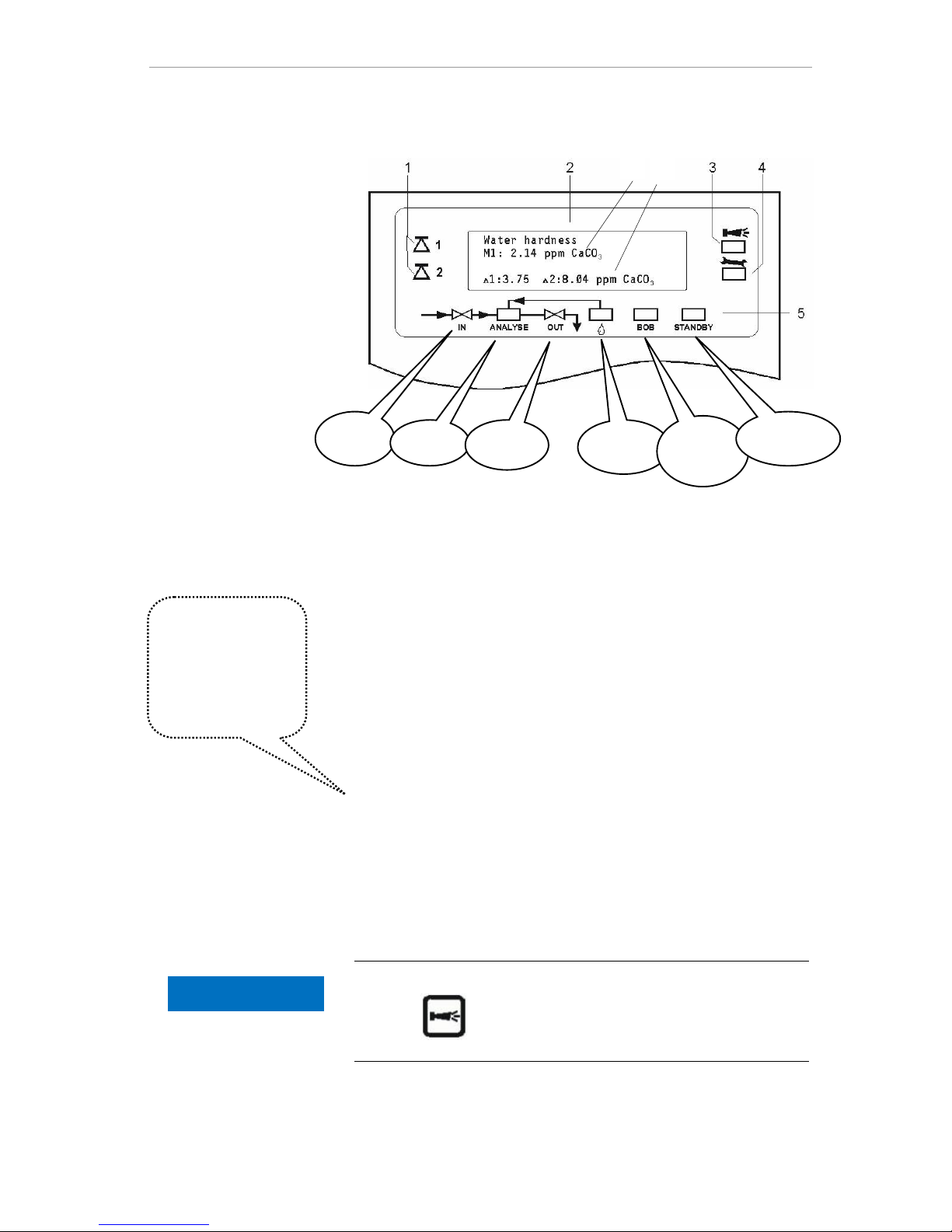
Display functions
1 Limit value status displays (red/green)
The display 1 illuminates red if limit value 1 has been reached or
exceeded. The display 1 illuminates green if the value falls below
the limit value. The same principle applies to limit value 2 and
display 2.
2 Text display (4 lines)
Displays the current analysis result as well as all important
statuses and programming data.
2a = The current measured value for measuring point 1 (M1) and
2 (M2) is displayed in line 2 and 3.
Value falls below the measuring range = "<" e.g. M1: < 0.89
ppm CaCO3
Value exceeds the measuring range = ">" e.g. M1: > 179
ppm CaCO3
2b = The set limit values LV1 and LV2 are displayed in line 4
3 Alarm (red)
Indicates malfunctioning/error message or warning message.
4 Maintenance message (yellow)
Indicates current maintenance requests
5 Status display of the active instrument components (line)
Six displays indicate the current instrument and analysis status
Cancelling error messages/warning messages
Press to acknowledge the message and, if necessary,
eliminate the cause of the fault.
All error and
warning messages
are alternately
shown in line 1 of
the standard
display!
NOTE
Page 20
Functions of the operating and display elements
20
Programming
keys
(cursor block)
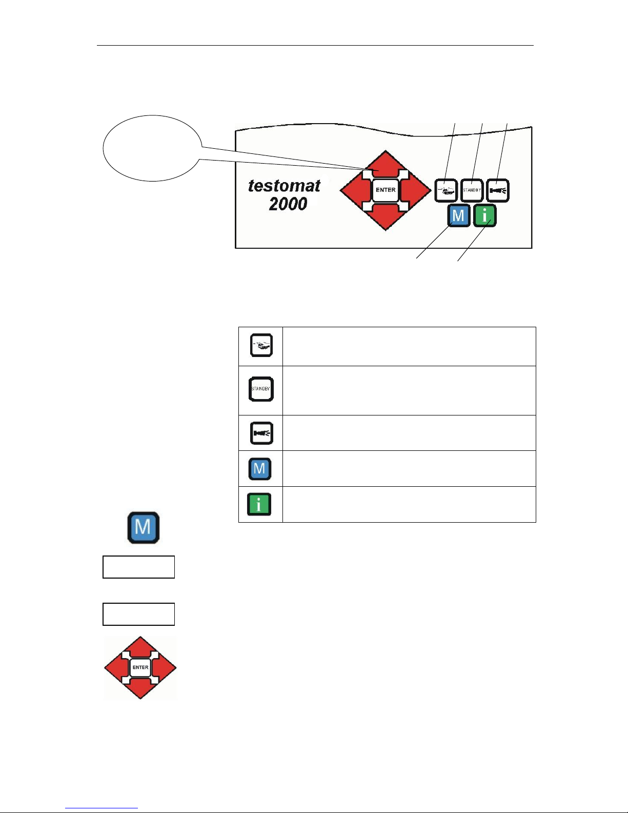
Operating elements and function keys
If you wish to carry out settings or enter data, or if alterations are
necessary, press the "M" key to open the programming mode. Use
this key when in the menu to go to the higher order menu items or to
exit the programming mode. Please note: The basic program is
password protected!
Programming keys (cursor block)
Use the programming keys (cursor block) to navigate in the menu, to
select the desired functions and to enter necessary instrument and
plant specific data. Press the "ENTER" key to select the submenu
item and to confirm and accept the selection or data input.
Function keys
Press the "manual" key to start an analysis by hand
Press the "STANDBY" key to put the instrument into
standby mode (automatic analyses are not carried out:
analysis stop)
Press the "Horn" key to acknowledge error and
warning messages
Press the "M" key to open the programming menu for
user specific and instrument specific settings
Press the "i" key to call all instrument information and
settings
(M)enu key
Cursor block
Page 21
Functions of the operating and display elements
21
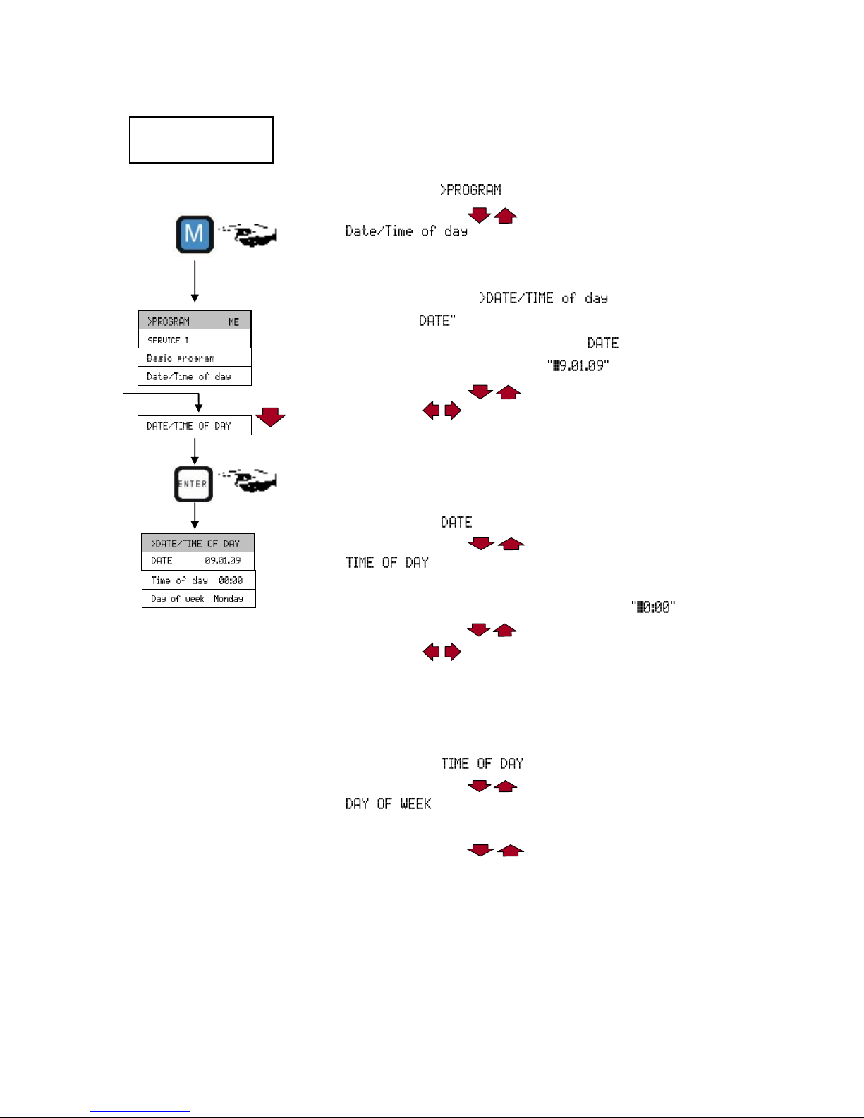
Operating system
Instrument settings and data input
Date, time and weekday input
Press the "M" key
The basic menu " " appears
Use the cursor block to select the desired menu item
" "
The selection appears in CAPITAL LETTERS.
Press "ENTER" to confirm your selection
The selected submenu " " appears
The menu item " has already been selected (capital letters)
Press "ENTER" to confirm the menu item " "
The cursor flashes in the date field:
Use the cursor keys to select the desired number
Use the keys to move the cursor to the next input field
Repeat this input process until the year has been entered
Press "ENTER" to confirm the entry
The date has now been entered.
Exit the menu item " " in order to set the time.
Use the cursor block to select the desired menu item
" "
Press "ENTER" to confirm your selection
The cursor flashes at the first position of the time:
Use the cursor keys to select the desired number
Use the keys to move the cursor to the next input field
Repeat this input process until the seconds have been entered
Press "ENTER" to confirm the entry
The time has now been entered.
Exit the menu item " " to set the weekday
Use the cursor block to select the desired menu item
" "
Press "ENTER" to confirm your selection
Use the cursor block to select the selected weekday
Press "ENTER" to confirm the entry
Press the "M" key twice to end programming
The standard measured value display appears on the display
Testomat instrument
(display) in display mode
▼▲
Page 22
Password protection and basic program
22
Password protection and basic
program
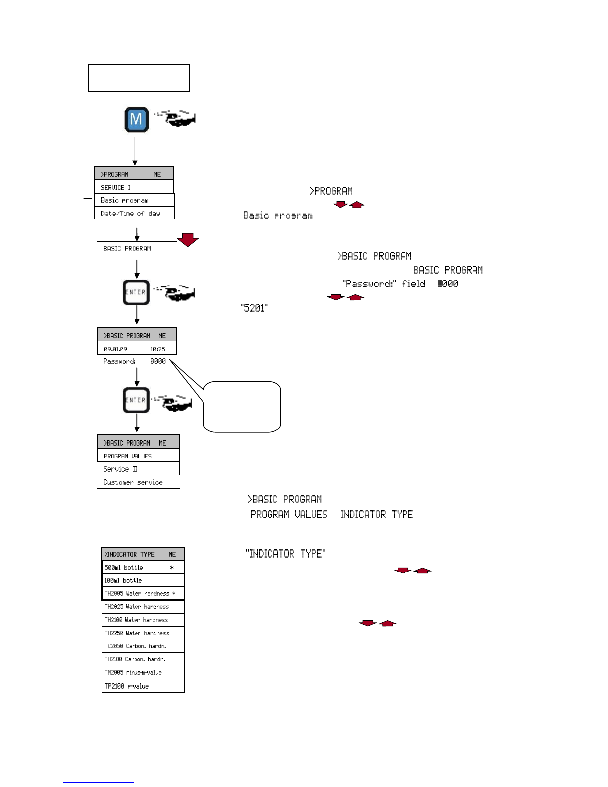
A four-digit password is required to enter data and to carry out
settings in the basic program. The password is the current time of
Testomat 2000® in reverse order.
Password entry
Press the "M" key
The basic menu " " appears
Use the cursor block to select the desired menu item
" "
The selection appears in CAPITAL LETTERS.
Press "ENTER" to confirm your selection
The selected submenu " " appears
Press "ENTER" to confirm the menu item " "
The cursor flashes in the
Use the cursor keys to enter the time in reverse order:
Press "ENTER" to confirm the entry
The selection menu for the basic program appears. You can now
enter the plant specific data.
Entering basic program data
Selecting the indicator and the bottle size
In , select
=> =>
Press "ENTER" to confirm the selection
The menu shown on the left appears
Select the size of the indicator bottle
(A 500 ml bottle " * " is factory set)
Press "ENTER" to confirm the selection
(An asterisk " * " appears at the end of the line)
Select the type of indicator
(The indicator type TH2005 " * " is factory set)
Press "ENTER" to confirm the selection
(An asterisk " * " appears at the end of the line)
The asterisk " * " displays the active menu item.
The indicator has now been selected.
▼▲
▼▲
▼▲
Please enter the
time in reverse
order:
=> 5201
Testomat instrument
(display) in display mode
▼▲
Page 23
Password protection and basic program
23
Selecting the operating mode
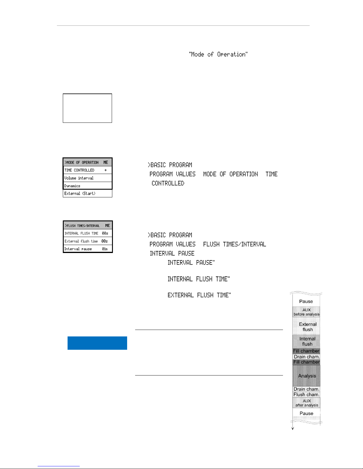
Under the menu item it is possible to select
the type of analysis controller. Testomat 2000® provides numerous
selection options: Time control, quantity control via water meter,
dynamic analysis start and external analysis start.
Shortest interval = 0 minutes between analyses. Largest interval = 99
minutes.
The analysis interval (time between two analyses) is determined by
the duration of the supplementary program AUX, the set flush times
(internal and external), the programmed interval and the duration of
the analysis. The analysis duration depends directly on the
measured value.
Selecting the time control
In , select
=> => =>
Press "ENTER" to confirm the selection
(An asterisk " * " appears at the end of the line)
("TIME CONTROLLED" " * " is preset)
Enter the interval pause and the flush times
In , select
=> =>
=>
Enter the " in minutes (m)
(1 minute is preset)
Enter the " in seconds (s)
(00 seconds (s) is preset)
Enter the " in seconds (s)
(00 seconds (s) is preset)
Press "ENTER" to complete all the entries
Duration of the analysis interval
The analysis interval is the addition of the "AUX
before/after analysis", "Internal flush" and "External flush"
times and the measuring value dependent analysis
duration (see diagram on the left)
Time controlled
Internal start via a
timer.
▼▲
▼▲
Analysis
interval
Sequence of
times
NOTE
Page 24
Password protection and basic program
24
Minimum interval = 1 litre, maximum interval = 9999 litres. The
analysis is carried out once the programmed water quantity has been
measured. The line and the measuring chamber are flushed prior to
the analysis (observe the programmed flush times).
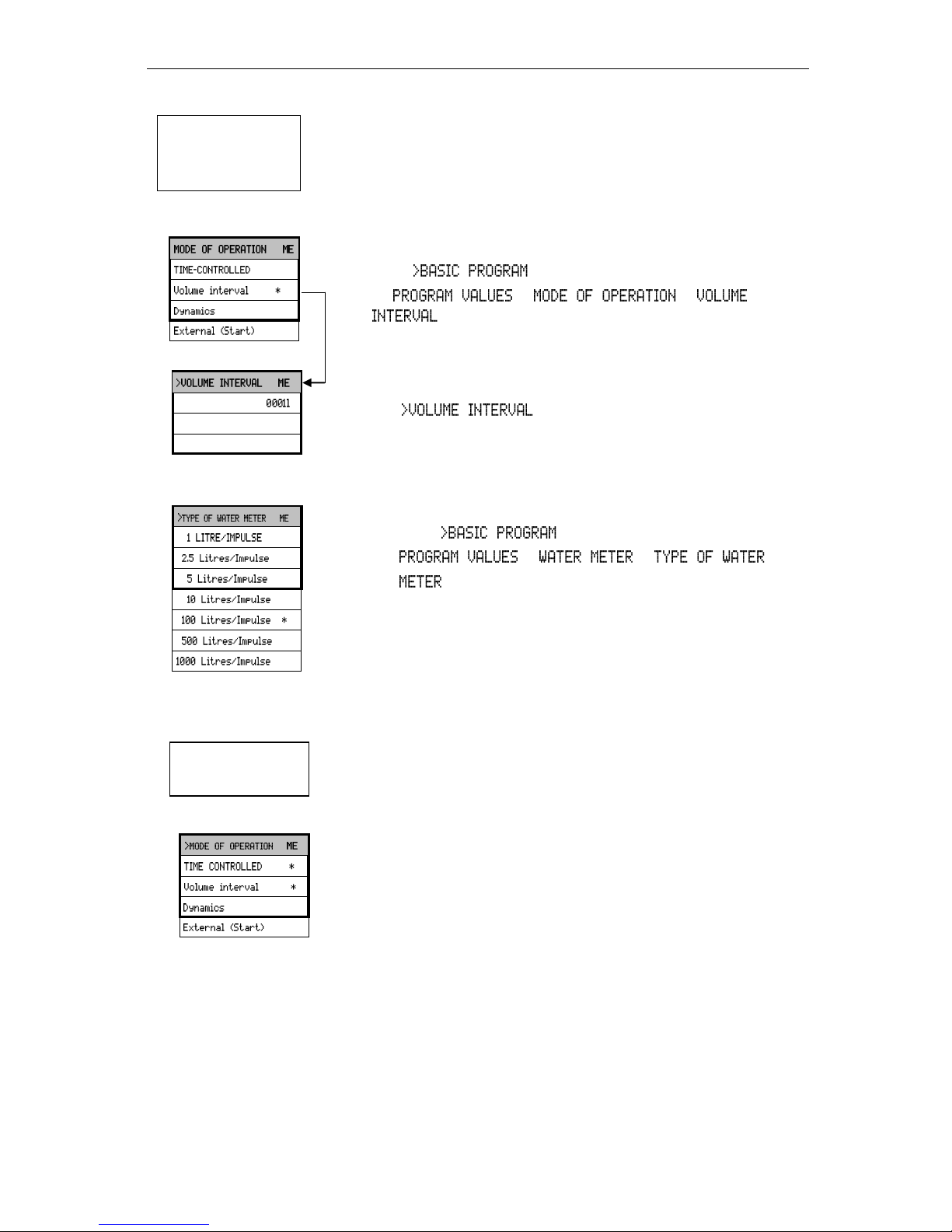
Selecting the volume control
In the menu, select
=> => =>
Press "ENTER" to confirm the selection
(An asterisk " * " appears at the end of the line)
The menu appears
Enter the respective flow rate in litres
Press "ENTER" to confirm the entry
Selecting the type of water meter
Select the menu
=> => =>
Select the water meter constant (litre/impulse)
(100 litres/impulse " * " is factory set)
Press "ENTER" to confirm the selection
The analysis is carried out once the programmed water quantity has
been measured. An analysis is always triggered with higher priority
when the programmed interval time has been reached.
Selecting the volume control/time priority
The process is the same as for "Selecting the time control"
The process is the same as for "Selecting the volume control"
Press "ENTER" to confirm all the entries
▼▲
Volume controlled
Start via water meter
Volumen control /
Time priority
▼▲
▼▲ ▼▲
Page 25
Password protection and basic program
25
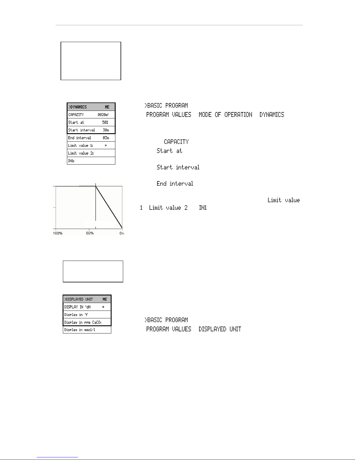
Dynamic analysis start: Depending of the exhaustion of the water
treatment plant, the interval period automatically decreases when the
residual capacity of the plant decreases. This involves the amount of
water used by the plant being determined. The start interval is reset
when limit value 1 or 2 is exceeded or via a signal at input IN1
(regeneration message from the process controller/filter controller).
Selecting dynamic start
In , select
=> => =>
Press "ENTER" to confirm the selection
The menu on the left appears.
Enter the " " of the plant in m3
Under " ", enter the start of dynamic operation as a
percentage (%) of the capacity
Under " ", enter the analysis interval in minutes
(m) that is desired for the start of dynamic operation
Under " ", enter the analysis interval in minutes (m)
that is desired for the end of dynamic operation
Select the type of reset to the start interval either via "
", " " or " "
Press "ENTER" to confirm the entry
(An asterisk " * " appears at the end of the line)
External analysis start
External analysis start occurs via a contact at the start input.
Selecting the display unit
It is possible to program the unit of the displayed value. The units dH,
°f, ppm CaCO3 and mmol/l can be selected. All the following inputs
and displays will then be displayed in the programmed unit.
In , select
=> =>
Select the desired unit
Press "ENTER" to confirm the selection
Dynamic
analysis start
Filter capacity dependent
control of the analysis interval
▼▲
Residual filter capacity (%)
Analysis interval time (min)
Start interval
Start at 40%
End interval >
External
analysis start
▼▲
Page 26
Entering further basic program data
26
Entering further basic program data
For selecting and entering data for these functions, please proceed
as described under "Entering basic program data".
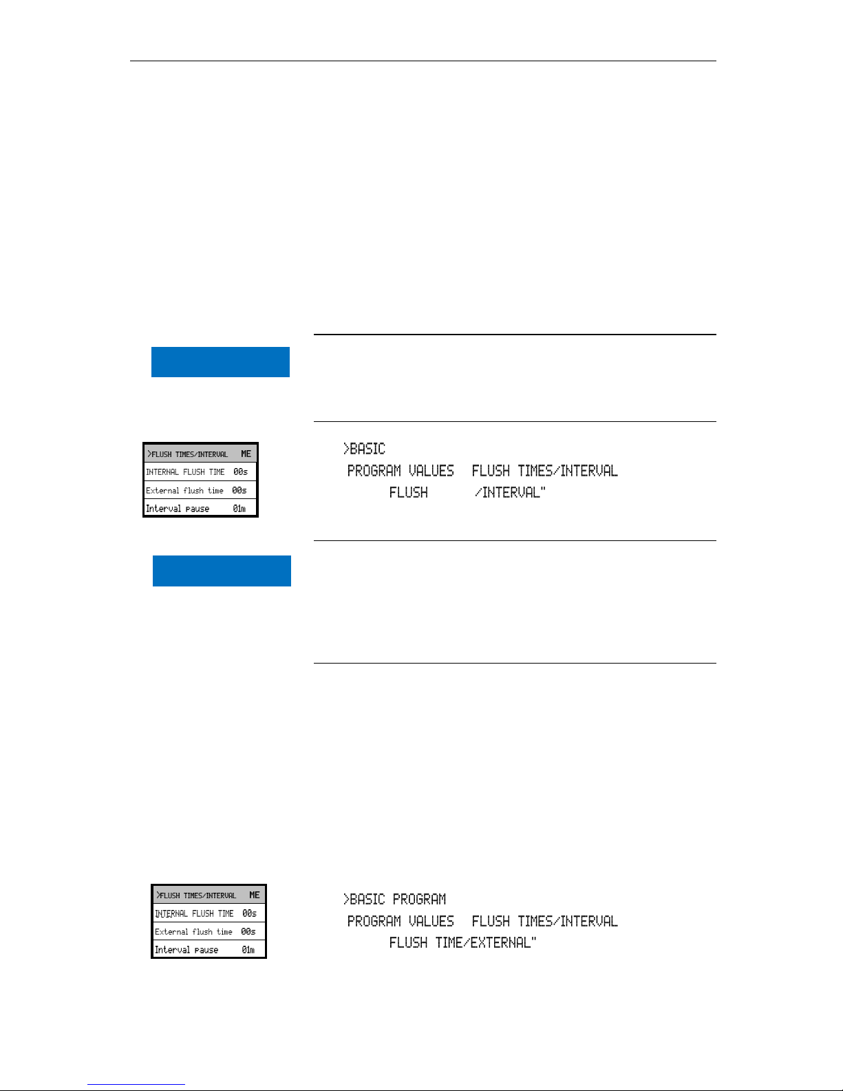
Internal flushing
To ensure that the analysed sample represents the current value, the
sampling line must be sufficiently flushed. If the plant has been out of
operation for a longer period or in case of long analysis intervals, we
recommend you to select a flushing time greater than 60 seconds.
Flushing starts by simultaneously opening the inlet and the outlet
valve of Testomat 2000®.
Duration of the analysis interval
The analysis interval depends directly on the programmed flushing
time. If, e.g., a flushing time of 90 seconds has been set, the actual
analysis interval cannot be less than 90 seconds.
In PROGRAM, select
=> =>
Enter the " TIMES in seconds (s)
Press "ENTER" to confirm the entry
Setting the internal flushing time
For connections longer than 3 m and with an internal hose
diameter of 6 mm a minimum internal flushing time of 10 seconds
is required to ensure that a valid sample is taken from the sampling
line. The required quantity of flush water for one-minute internal
flushing is 0.5 litres.
External flushing
If very short analysis intervals are required, or if a very long (several
metres) sampling line or a line with a large diameter is used, an
external flush valve should be installed upstream of Testomat 2000®.
The external flush valve has to be connected to the "Flush” outlet. If
the unit is used for monitoring two measuring points, external flushing
prevents incorrect measurements caused by sample mixing. The
external flushing time for the valve depends, just as the flushing time
for unit flushing does, on the length and diameter of the supply line to
Testomat 2000®.
In , select
=> =>
Enter the " in seconds (s)
Press "ENTER" to confirm the entry
▼▲ ▼▲
NOTE
NOTE
Page 27
Entering further basic program data
27
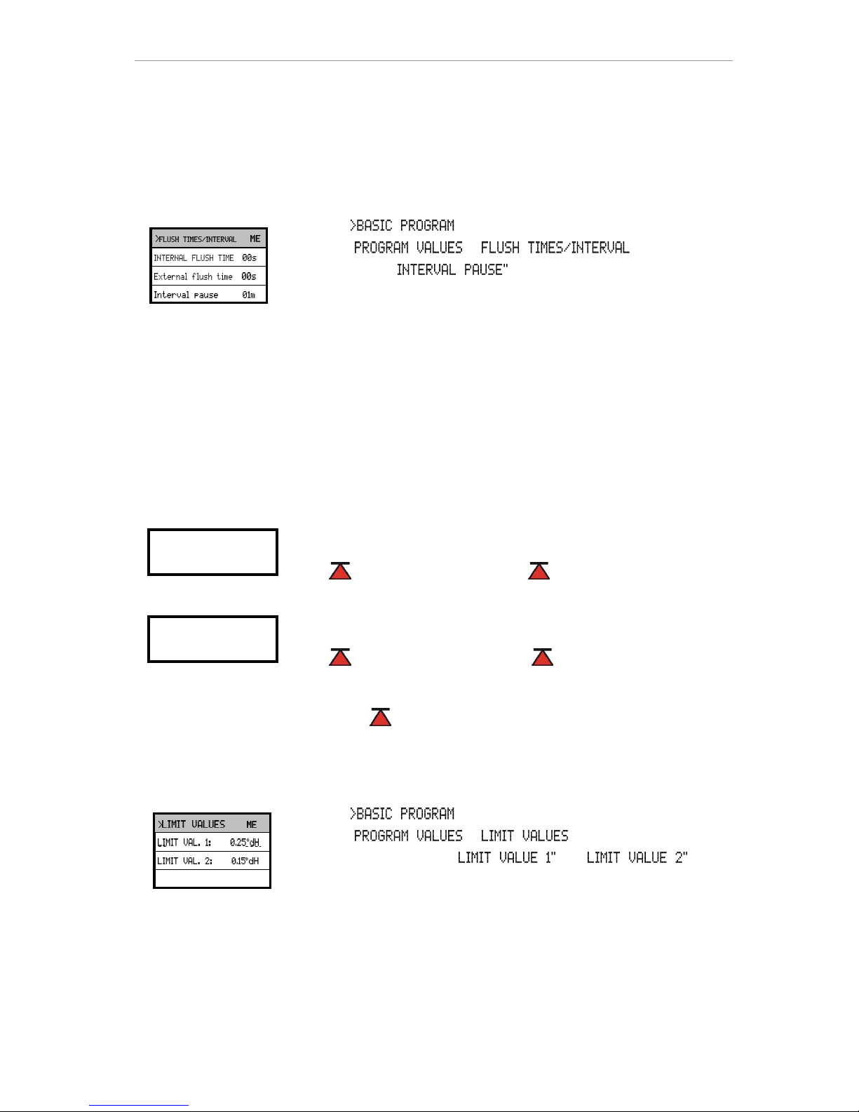
Interval pause
If the analysis is triggered via a timer, the interval between two
analyses (plus flushing time) is determined by the interval pause. The
shortest interval can be 0 minutes. In this case, analyses are carried
out continuously. The longest interval is 99 minutes.
In , select
=> =>
Enter the " in minutes (m)
Press "ENTER" to confirm the entry
Limit value monitoring
It is possible to program the limit values on a continuous scale. The
limit value range depends on the used indicator type and the
programmed unit. Two limit value outputs are available for
monitoring. This ensures that two limit values or two measuring
points can be monitored. The functions of the allocated relay outputs
can be programmed independently of each other.
If the unit is used for monitoring two limit values, the limit value
outputs are permanently allocated to these limit values!
1 LV1 = Limit value 1 2 LV2 = Limit value 2
If the unit is used for monitoring two measuring points, the limit value
outputs are permanently allocated to these measuring points!
1 LV1 = Measuring point 1 2 LV2 = Measuring point 2
If the limit value LV1 has been exceeded, the limit value control
display 1 lights up RED and the relay output LV1 reacts as
programmed in the switch function. If the limit value has not been
exceeded, the display lights up GREEN. The same applies for the
limit value LV2.
In , select
=> =>
Enter the values for " or "
Press "ENTER" to confirm the entry
Monitoring of two
limit values
Monitoring of two
measuirng points
▼▲
Page 28
Entering further basic program data
28
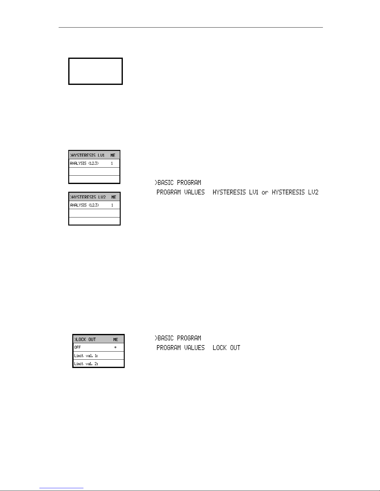
Hysteresis
The respective limit value output only switches after the first, second
or third bad analysis (suppression of the first or the second measured
value). This increases the reliability of the analysis evaluation, e.g.
after the measuring point has been switched over or if the sampling
line has not been flushed sufficiently. The hystereses of the two
outputs LV1 and LV2 can be set independently of each other.
With a hysteresis of "2", the next analysis is immediately carried out
when the limit value of this analysis has been exceeded for the first
time. The respective output is only switched after the limit value of
this analysis has been exceeded for a second time. With a hysteresis
of "3", the respective output only switches when the limit value of this
analysis has been exceeded for a third time. This setting is only
reactivated once the value has fallen below the limit value!
(The basic setting for LV1 and LV2 is 1)
In , select
=> =>
Enter the number of analyses
Press "ENTER" to confirm the entry
Lock out
Analysis monitoring with locking after the first, second or third time a
limit value is exceeded (= hysteresis) is used for error diagnosis. If a
limit value (programmable: LV1 or LV2) is exceeded as often as
programmed (limit value output switched), the instrument remains in
the analysis position and switches to standby (indicator lamp
"STANDBY" illuminates). In the LOCKING position (display
"STANDBY"), the sample remains in the measuring chamber. This
ensures that the analysis result can be visually checked for faults
caused by external effects (e.g. when measuring the water hardness,
excessive iron or copper content results in brown colouration).
Locking is cancelled via the "STANDBY" key.
In , select
=> =>
Select the function for LV1 and/or LV2
(An asterisk " * " appears when the function is active)
Press "ENTER" to confirm the entry
Analysis requests via a signal at the START input are
suppressed!
Suppression of
bad analyses
Page 29
Entering further basic program data
29
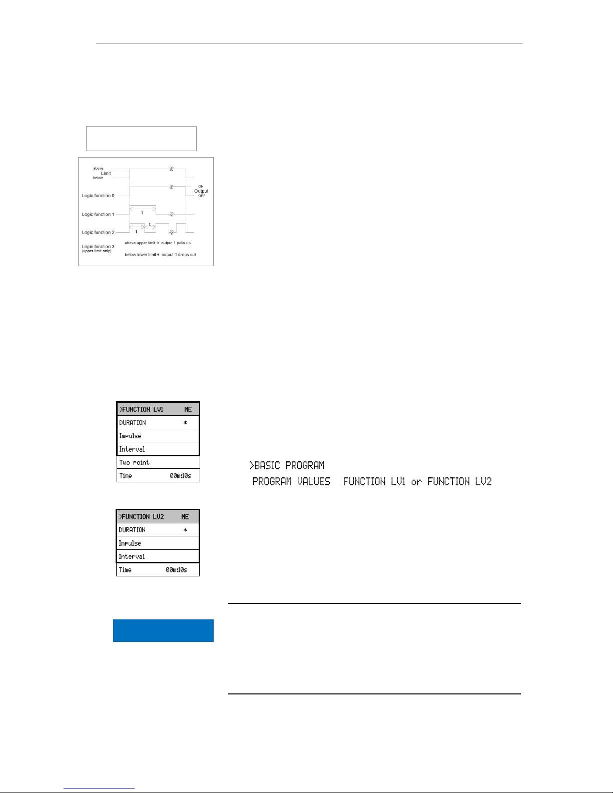
Switch functions of the limit value outputs
LV1 and LV2
Switch function 0, duration
If the limit value LV1 or LV2 has been exceeded, the output relay LV1
or LV2 reacts. If the measured value falls below the limit value LV1
or LV2 without locking, the relevant relay drops out again.
Switch function 1, impulse
If the measured value exceeds the limit value LV1 or LV2, the
relevant output switches for a settable time (t).
The respective output always remains switched for the set time,
irrespective of how long the limit value has been exceeded. A new
impulse is only possible once the value has fallen below the limit
value!
Switch function 2, interval
If the limit value has been exceeded, the respective output switches
at intervals with the settable time (t) = impulse or interval as long as
the limit value is exceeded. The switching on time and the interval are
the same.
Switch function 3, two-point
If the upper limit value LV1 has been exceeded, the output relay LV1
switches. If the value falls below the lower limit value LV2, the output
relay LV1 drops out again. The output relay LV2 switches according
to the programmed switch function.
In , select
=> =>
Select the duration, impulse, interval or two-point (only for LV1)
Enter the time (only for switch function 1 and 2)
Press "ENTER" to confirm the entry
The function 3 is only possible if different values are used for the limit
values LV1 and LV2 with just one measuring point. For example, for
LV1 = 0.2 °dH and for LV2 = 0.1 °dH.
Switch functions and locking
Switch functions 0 and 2: If locking has been programmed, the
output relay LV1 switches as programmed until manually released
(press the "STANDBY" key).
If locking has been programmed, switch function 3 cannot be
selected!
▼▲
▼▲
Schematic representation
of logic functions
NOTE
Page 30
Entering further basic program data
30
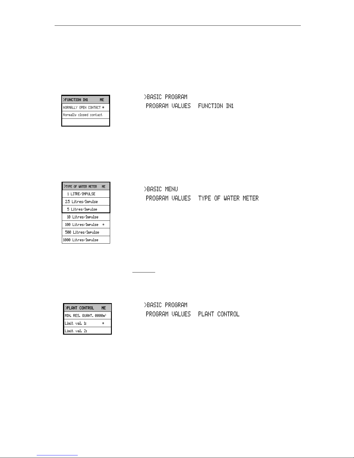
Function IN1
For dynamic analysis control or programmed plant monitoring, the
regeneration message from the controller of the water treatment plant
must be connected to IN1 (isolated contact required!). The active
status of IN1 has to be programmed according to the output function
of the controller.
In , select
=> =>
Select a normally closed or normally open contact
Press "ENTER" to confirm the entry
Water meter
It is necessary to connect a water meter to input IN2 for quantitydependent analysis start, for dynamic analysis control and for
monitoring the operation of the water treatment plant (plant
monitoring). Program the corresponding water meter rating.
In , select
=> =>
Select the water meter rating
Press "ENTER" to confirm the entry
Plant control
In order to monitor the plant, it is possible to determine a specific
quantity of water at which the limit value should not be exceeded
(LV1 or LV2).
Example: A "GOOD" quantity of 50 m3 has been entered. If the
quantity of water produced between two violations of the limit value is
less than the programmed quantity of water, either an alarm or a
message is triggered depending on the programming.
In , select
=> =>
Enter the "GOOD" quantity in m3
Press "ENTER" to confirm the entry
The flashing error display "Plant control" appears.
The quantity of water for plant monitoring is reset after exceeding
LV1 or LV2, or via a signal at input IN1 (regeneration message from
the process controller), or manually in the SERVICE II menu via the
plant control RESET.
Monitoring does not occur if 0 is entered for the quantity of water
(min. GOOD quantity).
▼▲
▼▲
▼▲
Page 31
Entering further basic program data
31
BOB operation (operation without permanent
supervision)
BOB (operation without permanent supervision) is a safety relevant
feature when using the instrument as a water hardness monitoring
unit for monitoring steam boiler plants in accordance with TRD 604.
If the BOB function has been programmed, the instrument
continuously checks the available amount of indicator. A measuring
value of 0.083 °dH (= 0.015 mmol/l alkaline earth ions) is decisive for
the calculation of indicator consumption per analysis. If the residual
amount is insufficient for the set BOB period (programmable 24 - 120
h), an alarm message is output.
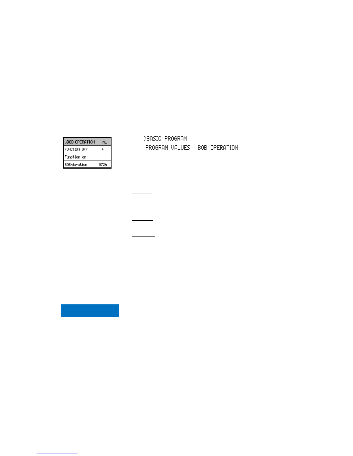
In , select
=> =>
Select "FUNCTION ON"
Enter the time period in hours (h) under "BOB DURATION"
Press "ENTER" to confirm the entry
BOB on: Continuous monitoring of the residual amount of indicator.
ALARM message "low indicator level" when the amount of indicator
falls below the minimum quantity for the BOB time period: BOB
flashes, the ALARM output is switched.
BOB off: No BOB function. Monitoring of the residual amount of
indicator only to minimum quantity (filling level 10%)
Example:
BOB time period = 72 hours Number of analyses per hour = 10
Required amount of indicator for 72 h = 72 h x 10 analyses/h x (3 x
30) μl/analysis = 64.8 ml.
(This corresponds to a filling height of approx. 13% for a 500 ml
bottle)
Using BOB operation
BOB operation is not possible with the operating mode "volume
control"!
Only select the operating mode "time-controlled"!
NOTE
Page 32
Entering further basic program data
32
Alarm/Message
The instrument is equipped with an alarm relay output for signalling
faults. The events which mean a fault at the instrument or are
intended to trigger a message, can either trigger an alarm "A"
(continuous contact) or a message "M" (2-second impulse).
The faults are recorded and stored in the error history if the event has
been programmed as an alarm or message. For example, if a low
indicator level has not been programmed as an ALARM/MESSAGE,
it is not registered in the error history. Up to 20 error messages can
be stored. A list of these errors can be opened in the information
menu. The information stored per event is the time (day, month, year
and hour) and the type of the error.
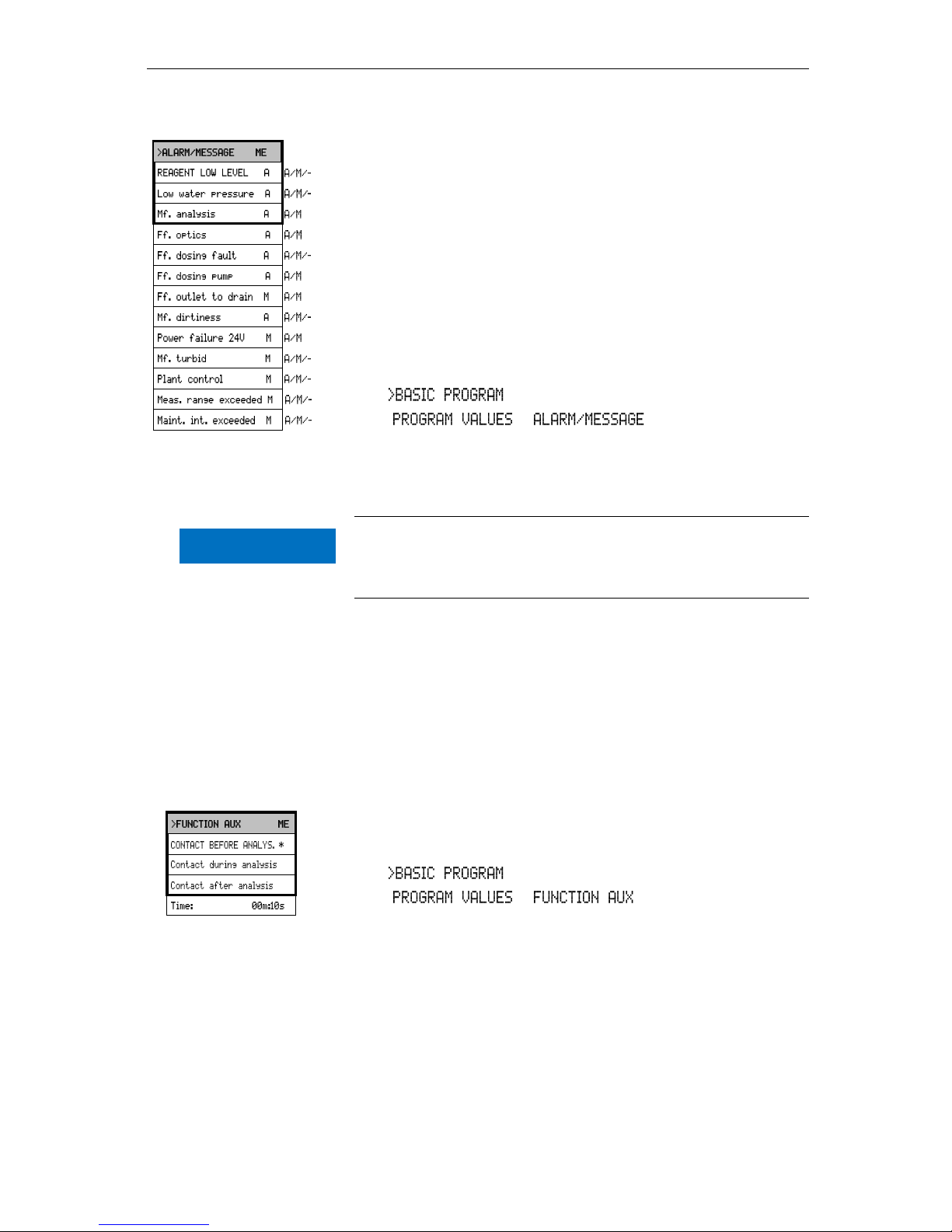
In , select
=> =>
Select the type of monitoring A=alarm, M=message or - = no action
for the individual menu items
Press "ENTER" to confirm the respective entry
Error messages
All error messages are lost after a power failure.
Certain instrument faults always trigger an alarm or a message!
Function AUX
The AUX relay output can be programmed for the following control
functions:
- As a function output for the contact with programmable
duration prior to and/or during the analysis, or after an analysis.
For example, it is possible to control the cooling water inlet of an
upstream cooler via a solenoid valve. This ensures that the cooling
water only flows when required, i.e. when an analysis is being carried
out.
In , select
=> =>
Select the program step at which the AUX contact is to be
activated
Under "Time" enter the contact duration in minutes (m) and
seconds (s)
Press "ENTER" to confirm the entry
▼▲
NOTE
A=Alarm, M=Message
- = no action
Ff.=Function fault
▼▲
Page 33
Entering further basic program data
33
Cleaning function
After completion of the set number of analyses, the measuring
chamber is flushed. Subsequently, the cleaning agent is added to the
water in the measuring chamber. The contents of the measuring
chamber are emptied after a 30-second reaction time. The measuring
chamber is then flushed twice. To achieve the best possible cleaning
results, we recommend:
Testomat 2000 self clean cleaning solution, article number: 151105
Important safety information
Read the operating instructions carefully and thoroughly before
operating the instrument
Always adhere to the specifications in the safety data sheet when
using the cleaning agent
Do not dispense cleaning solution by hand. Only use cleaning
solution that has been approved by Gebr. Heyl. Components in the
device can be damaged by a wrong dosage or incorrect cleaning
solutions.
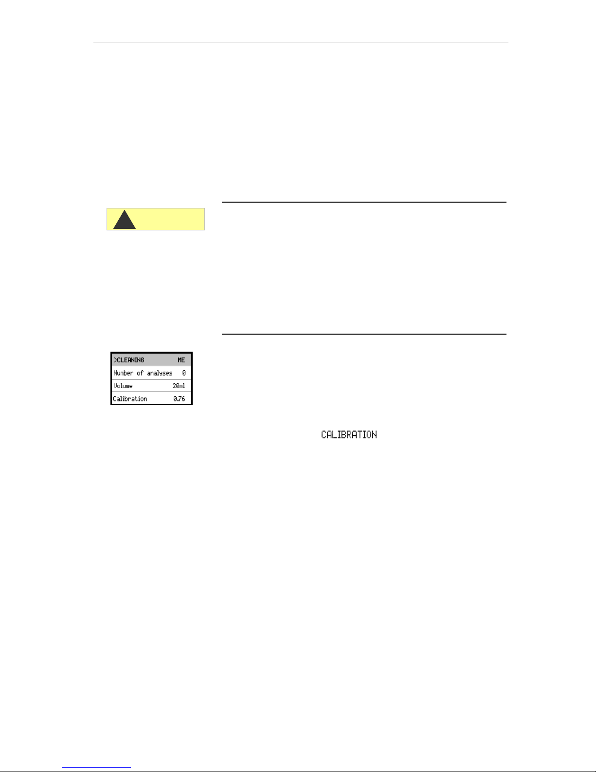
Here, you can set the number of analyses to be performed before
cleaning is carried out and set the amount of cleaning fluid that
should be used during the cleaning process. Enter 0 to switch off the
cleaning function.
To guarantee the accuracy of the set volume, the FLOWClip
membrane pump must be calibrated.
Select the menu item
Press “ENTER” to start the calibration process.
Calibration takes approximately 40 seconds. The determined delivery
rate is displayed in ml/s.
It is recommended to carry out calibration once the cleaning fluid
bottle has been replaced five times
CAUTION
!
▼▲
Page 34
Entering further basic program data
34
Service II
The service II menu contains various functions for monitoring the
operation of the instrument:
Programming of the maintenance interval, operation (reset) internal
data/setting, e.g. water quantity and plant monitoring.
Use of the Service II menu
The functions in the Service II menu directly influence the operation
and monitoring functions of the instrument and can result in plant
malfunctioning!
These tasks should only be carried out by trained and qualified
staff.
Reset operating time
After replacing a dosing pump or the measuring chamber holder, it is
possible to reset the current operating time to 0 hours.
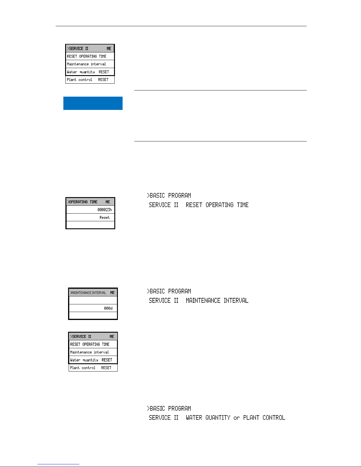
In , select
=> =>
Select "Reset" to reset the operating time
Press "ENTER" to confirm the selection
The operating time "000000h" appears on the display
Maintenance interval
Observance of the maintenance intervals is monitored and displayed
by Testomat 2000®. Program the desired maintenance interval in
days here. (0 days equals no maintenance interval)
In , select
=> =>
Enter the maintenance interval in days (d)
Press "ENTER" to confirm the entry
Water quantity RESET
Causes a reset of the currently stored water quantity. This has a
direct effect on the plant monitoring and the dynamic analysis control.
Plant control RESET
Plant monitoring is only re-activated when the limit value is exceeded
again.
In , select
=> =>
Press "ENTER" to confirm the entry
▼▲
▼▲
▼▲
▼▲
NOTE
Page 35
Description of the signal inputs/outputs
35
Description of the signal
inputs/outputs
Connecting the signal inputs
Only connect the signal inputs "Start", "Stop", "IN1" and "IN2" with
volt-free contacts!
The connection of external voltages would damage the instrument!
Function
Test
period
Action
Start
External analysis
start (only normally open)
None
In EXTERNAL operating
mode, an analysis is started
by triggering a contact at the
input.
Permanent contact results in
regular analyses.
Function
Test
period
Action
Stop
External analysis stop (e.g.
via flow controller or
process controller)
None
There are no analyses while
the contact at the input is
open or closed
An active Stop input prevents an analysis start, e.g. via a current
interval. This can be necessary if the plant does not supply water. A
current analysis is stopped when the input valve is opened (while the
measuring chamber is being flushed or filled). The water which has
already entered the measuring chamber remains there. If the
measuring chamber is already full, the analysis is executed. Manual
start has priority over the Stop input, i.e. if the Stop input is active, an
analysis can be started manually or a manually started analysis
cannot be stopped by the stop signal. In the operating mode “timecontrolled”, the interval time continues when the Stop input has been
activated.
In , select
=> =>
Select the type of contact
Press "ENTER" to confirm the selection
Start
terminals 20,21
Stop
terminals 22,23
▼▲
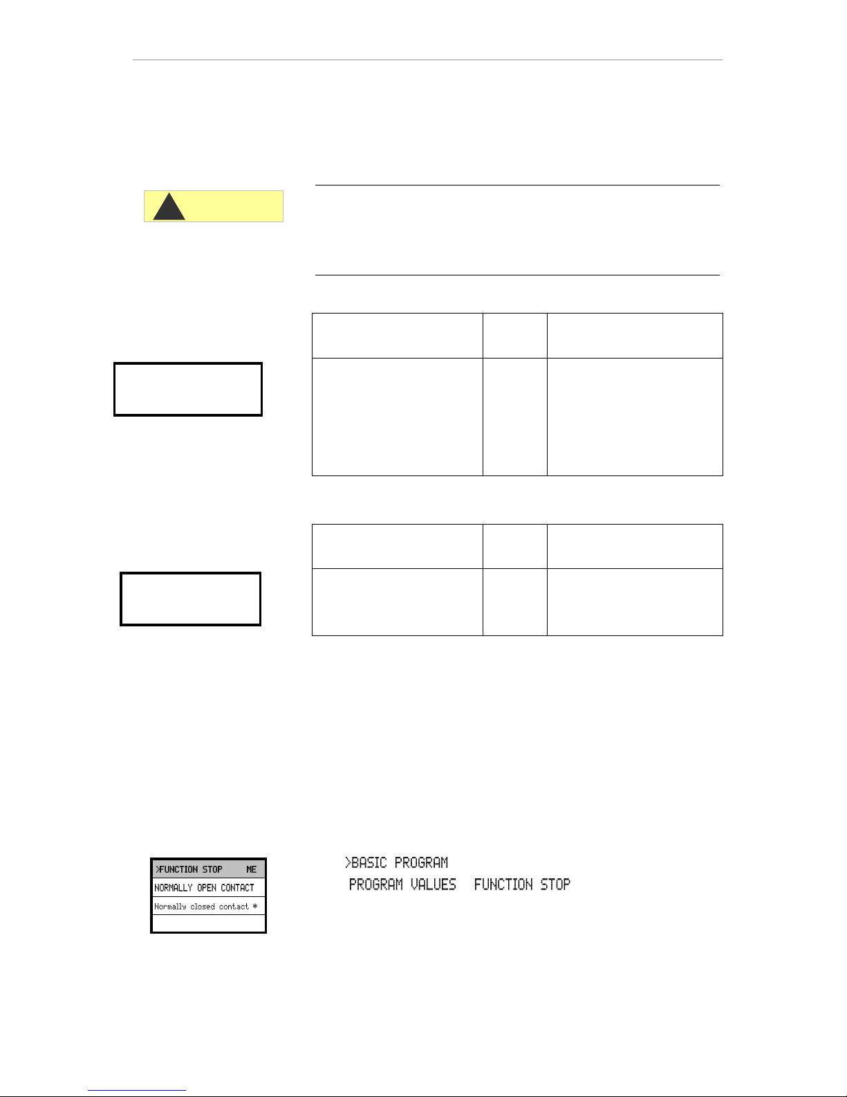
CAUTION
!
Page 36
Description of the signal inputs/outputs
36
Function
Test
period
Action
IN1
Message from the process
controller
(regeneration finished)
(Normally closed or normally
open)
Fixed,
10
seconds
Start of plant maintenance
and capacity reset to 100%
for dynamic
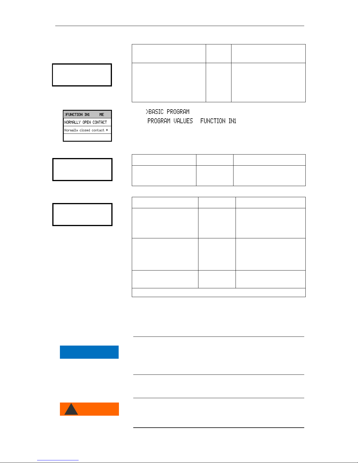
In , select
=> =>
Select the type of contact
Press "ENTER" to confirm the selection
Function
Test period
Action
IN2
Water meter input
None
Quantity recording for
analysis start and plant
monitoring
Function
Connection
Action
OUT
Programmable current
interface
0-20 mA or 4-20 mA
Max. load
500 Ohms
OR
Programmable voltage
interface
0-10 V or 2-10 V
OR
Serial interface RS 232
Serial bus
(2-wire cable)
See description of
interface card RS 910
Refer to the section entitled "Interfaces" for a detailed description
Interfaces (optional)
Current interface 0/4-20 mA
Current interface load
The maximum load of 500 Ohms should not be exceeded!
In case of possible faults and when using very long cables (approx.
20 m), a screened cable should be used, if possible.
Installing the interface cards SK910/RS910
Avoid static charges during installation!
Personnel responsible for installation must be appropriately trained
and qualified!
IN1
terminals 24,25
IN2
terminals 26,27
OUT
terminals ┴, 28,29
▼▲
Base circuit
board Testomat
WARNING
!
NOTE
Page 37
Description of the signal inputs/outputs
37
Switch off the instrument.
Insert the plug-in circuit board into the left-hand slot with the
component side on the left. (Contact no.1 is at the top)
Switch on Testomat 2000®.
Program the desired type of current (0/4-20mA) (for SK910).
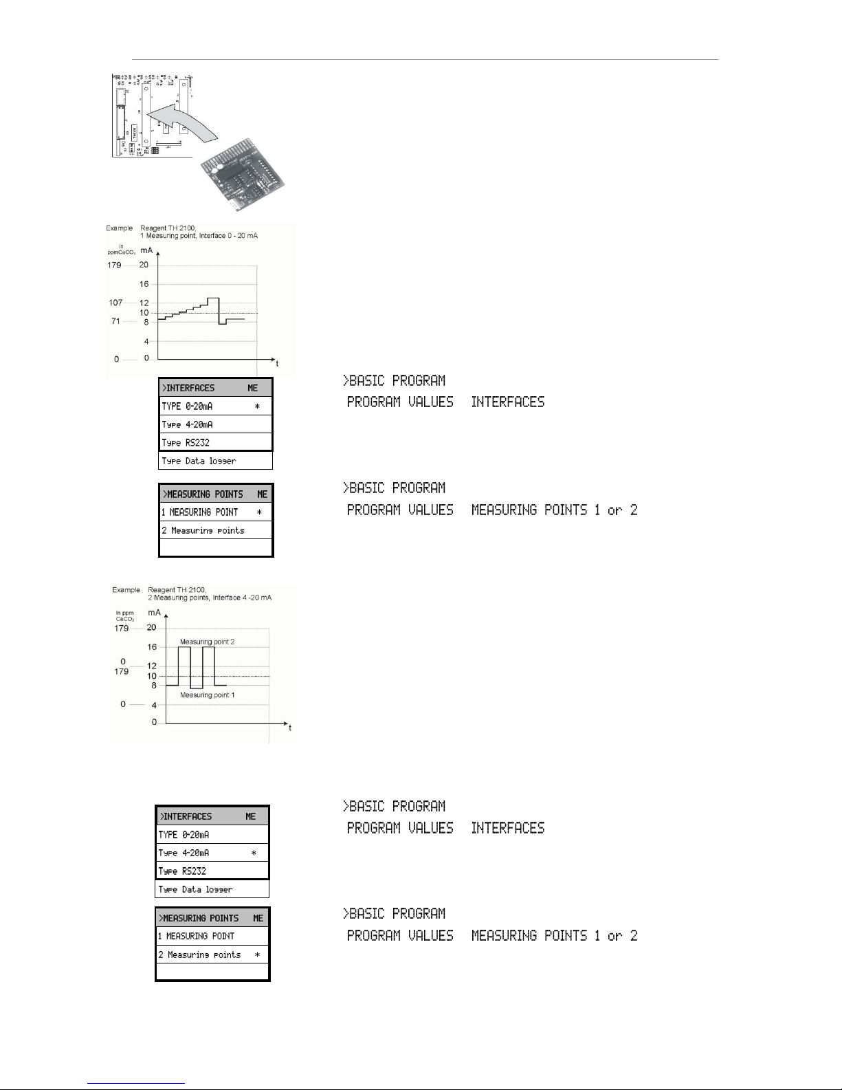
Monitoring a measuring point
A printer can be connected to record the analysis results. The
instrument is equipped with a programmable current output for this
purpose (optional 0-20 mA or 4-20 mA).
The example on the left displays the current profile in the 0-20 mA
range for one measuring point.
In , select
=> =>
Select the desired current range
Press "ENTER" to confirm the selection
In , select
=> =>
Select the desired configuration
Press "ENTER" to confirm the selection
Monitoring of two measuring points
The example on the left displays the current profile for 4 - 20 mA and
the use of two measuring points.
Measuring point 1 and measuring point 2 are measured alternatively.
The measured value 1 is shown in display line 2 (M1:) and the
measured value 2 in line 3 (M2:). The currently analysed measuring
point is indicated by an asterisk on the right.
The range of the current interface is divided. The range 4 – 12 mA is
available for the measured value from measuring point 1 and range
12 – 20 mA for the measured value from measuring point 2.
In , select
=> =>
Select the desired current range
Press "ENTER" to confirm the selection
In , select
=> =>
Select the desired configuration
Press "ENTER" to confirm the selection
▼▲
▼▲
▼▲
▼▲
Page 38
Description of the signal inputs/outputs
38
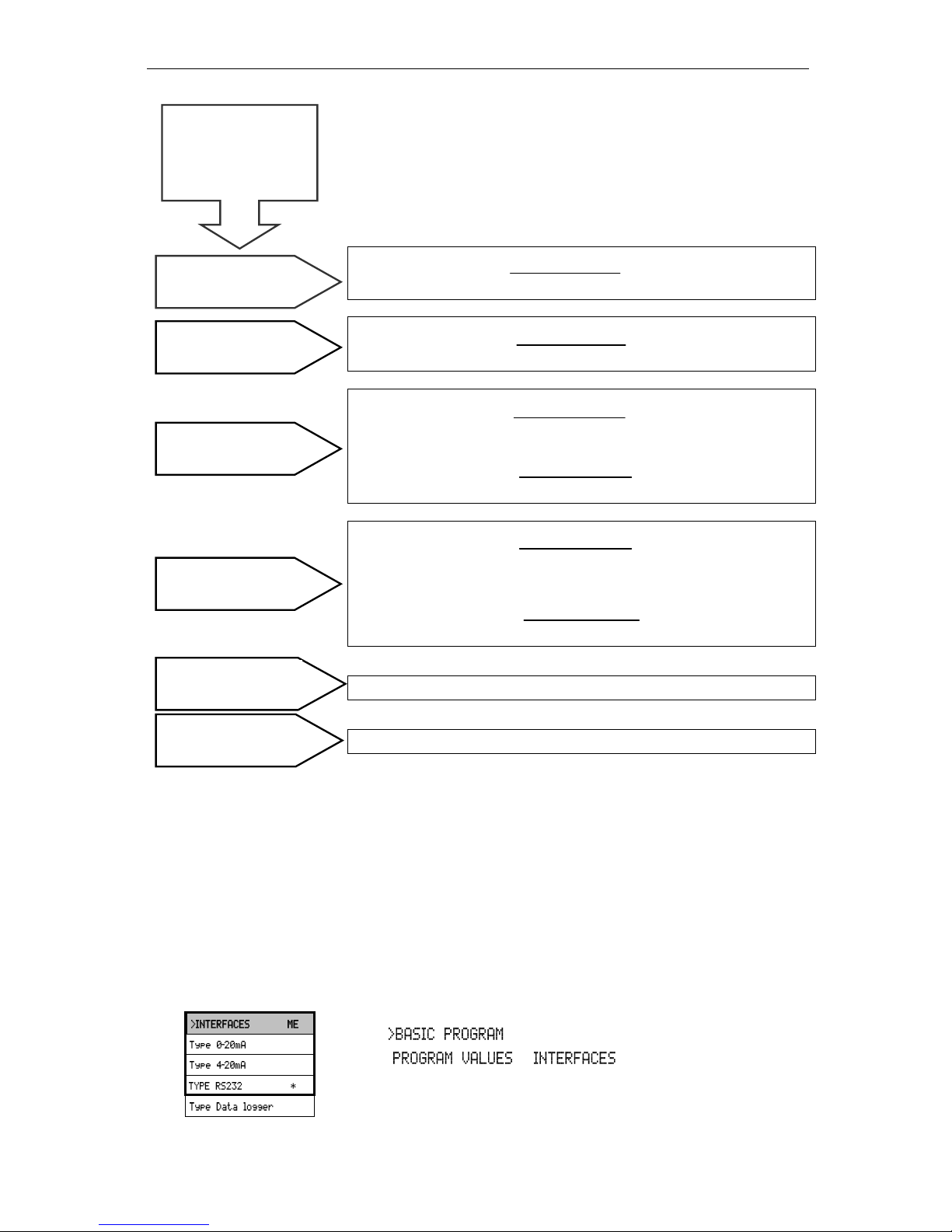
Calculation of output currents
The entire current range (0 – 20 mA or 4 – 20 mA) is available for
one measuring point. However, the current range is divided for two
measuring points. The value from measuring point 1 is displayed in
the lower half (0 – 10 mA or 4 – 12 mA) and the value for measuring
point 2 in the upper half (10 – 20 mA or 12 – 20 mA).
Measured value
Current = x 20 mA
Maximum value
Measured value
Current = x 16 mA + 4 mA
Maximum value
Measured value 1
Current 1 = x 10 mA
Maximum value
Measured value 2
Current 2 = x 10 mA + 10 mA
Maximum value
Measured value 1
Current 1 = x 8 mA + 4 mA
Maximum value
Measured value 2
Current 2 = x 8 mA + 12 mA
Maximum value
The current is set to 0 or 4 mA (for 1 measuring point)
The current is set to 20 mA.
Measured value = The value shown on the display in the selected
hardness unit
Maximum value = The end value of the applied indicator
(e.g. indicator 2005 = 0.5 °dH)
Serial interface RS232
Testomat 2000® can also be connected to a log printer via the serial
interface RS232 to enable the printout of measuring results and error
messages. Analyses can then be continuously logged. This option is
only possible in connection with the RS-232 interface card for log
printer, RS910 (Art. no. 270310).
In , select
=> =>
Select the desired interface
Press "ENTER" to confirm the selection
1 measuring point
0 - 20 mA
1 measuring point
4 - 20 mA
2 measuring points
0 - 20 mA
2 measuring points
4 - 20 mA
Measuring range not
achieved (e.g. <0.05 °dH)
Measuring range
exceeded (e.g. >0.5 °dH)
How is the current
calculated for a
specific measured
value?
▼▲
Page 39
Description of the relay outputs
39
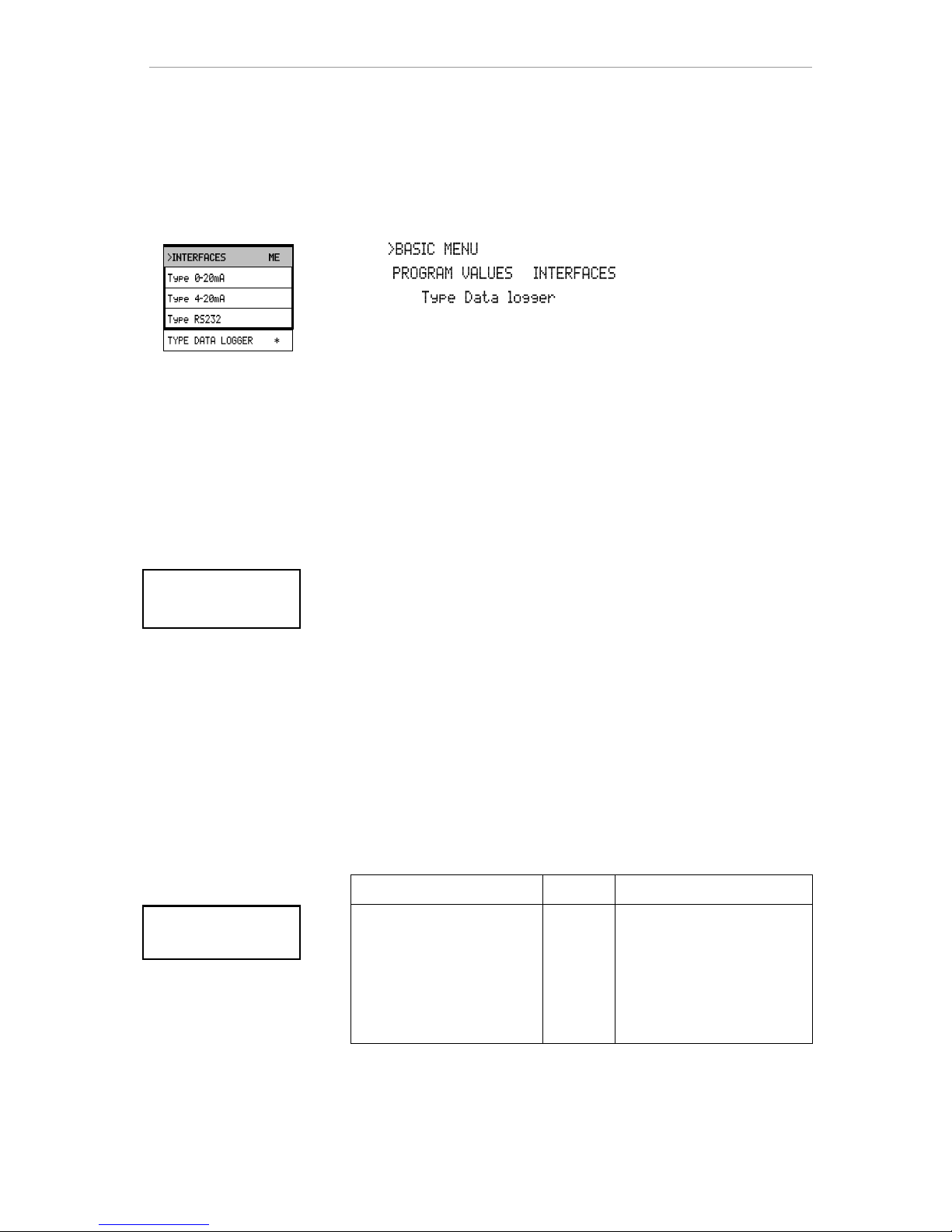
SD Card Data logger
Analyses can then be continuously logged by using an SD Card data
logger (art. no. 100490) with the Testomat 2000® POC.
To operate the data logger correctly, proceed as described below:
In select
=> =>
Select " “
Press "ENTER" to confirm the selection
Description of the relay outputs
All relay outputs are neutral contacts. This ensures that all connection
options are available. The switching of mains voltage and external
voltage, and the direct switching of inputs, e.g. a process controller,
can be realised.
Flushing (external flush valve)
Immediately before each analysis the external flush valve is opened
for the programmed period allowing the line up to Testomat 2000® to
fill with measuring water. Please ensure that the programmed flush
time is sufficient.
Please refer to "Entering further basic program data" "External
flush" for programming details
LV1 and LV2 limit value outputs
Two volt-free relay contacts are available to signal that a limit value
has been exceeded. The limit values, the hysteresis and the switch
function can be freely programmed for both contacts.
Function
Contact
Action
LV1
Relay switches when the
limit value is exceeded at:
Limit value 1 or
measuring point 1
Volt-free
changeover
contact
Programmable:
- Continuous contact
- Impulse (1-99 seconds/minutes)
- Interval (1-99 seconds/minutes)
- Two-step controller (only for one
measuring point)
- Hysteresis (limit value is exceeded
once, twice, three times)
Limit value 1
terminals 3, 4, 5
Flush valve
terminals 1, 2
▼▲
Page 40
Description of the relay outputs
40
Function
Contact
Action
LV2
Relay switches when the
limit value is exceeded at:
Limit value 2 or
measuring point 2
Volt-free
changeover
contact
Programmable:
- Continuous contact
- Impulse (1-99 seconds/minutes)
- Interval (1-99 seconds/minutes)
- Hysteresis (limit value is exceeded
once, twice, three times)
Please refer to the section entitled "Switch functions of the limit value
outputs LV1 und LV2" for more details and programming!
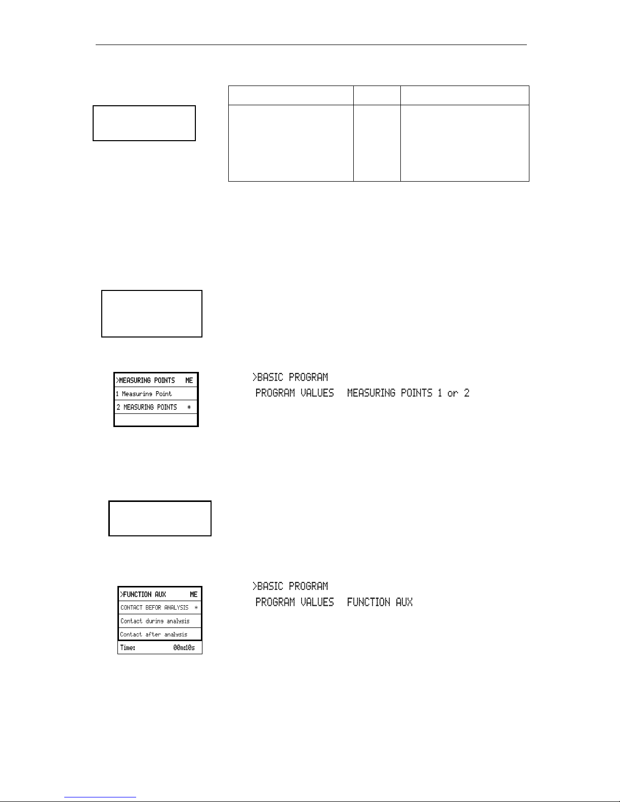
Measuring points 1 or 2 (measuring point switchover)
If the instrument is used for monitoring two measuring points, the
solenoid valves (individual valves or one 3/2-way control valve) of the
corresponding sampling line have to be connected to this output. The
terminals are strictly allocated to the measuring points.
Terminal 9 = Measuring point 1 , Terminal 10 = Measuring point 2
In , select
=> =>
Select "2 Measuring points"
Press "ENTER" to confirm the selection
AUX (programmable function output)
The functioning of this volt-free relay output is programmable:
1. For reporting a current analysis and/or
2. For contact prior to an analysis, e.g. to operate with a
cooler or
3. Contact after an analysis
In , select
=> =>
Select the program step at which the AUX contact is to be
activated
Under "Time" enter the contact duration in minutes (m) and
seconds (s)
Press "ENTER" to confirm the entry
Limit value 2
terminals 6, 7, 8
M. point
switch-over
terminals 9, 10, 11
▼▲
AUX
terminals 12, 13
▼▲
Page 41
Description of the relay outputs
41
Alarm (fault message output)
The "Alarm" output is a volt-free change-over relay contact. During
trouble-free operation, the contact between the terminals 15 – 16 is
closed and the one between terminals 14 – 16 is open. In case of a
voltage breakdown, the contact between the terminals 14 – 16 is
closed and the one between terminals 15 – 16 is open.
The instrument is equipped with a range of monitoring functions. You
can define the individual statuses as a fault and program the
corresponding message either as a continuous contact (A) or as a
message impulse (M).
Functions/Behaviour of the "Alarm" output:
- With a continuous contact, the "Alarm" output remains activated
(terminals 14 – 16 closed) as long as the fault persists.
- With a message impulse, the output is switched 'on' for 2
seconds and then switched 'off' for 5 seconds.
- If several faults with differently programmed messages are
signalled simultaneously, the output is switched to continuous
contact.
- The red LED "Alarm" and the text on the display indicate a fault.
- The fault message signal at the "Alarm" output is deleted by
confirming the fault via the "Horn" key.
- The error message can only be deleted if the fault has been
eliminated.
- Exception: The maintenance has been exceeded. This message
is confirmed in the M menu, see below (Maintenance).
- Each new fault is entered into the error history (also see "i
menu").
- There is no additional alarm via the fault message output when
the limit value is exceeded!
The error messages are described under "Error messages/
Troubleshooting"
Maintenance (output for maintenance message)
The "Maintenance" output is a volt-free change-over contact. During
trouble-free operation without a programmed maintenance interval,
the contact between the terminals 17 – 19 is closed and the one
between terminals 18 – 19 is open.
The instrument is equipped with a range of monitoring functions and
a programmable maintenance interval. The respective maintenance
message is always a continuous contact.
A maintenance request is displayed via the yellow "Maintenance"
LED. The maintenance display can only be deleted once the status
has been corrected or after the maintenance request has been
confirmed.
Please refer to the section "Password protection and basic
programming" for further programming details.
Alarm
terminals 14, 15, 16
The following faults
activate the "Alarm"
output and are
displayed:
Always fault message
for:
Power failure
Low water level
Function fault optics
Measuring fault analysis
Function fault dosing pump
Function fault drain outlet
Function fault failure 24V
Programmable fault
messages for:
Low indicator level
Function fault dosing error
Function fault soiling
Measuring fault turbid
Plant monitoring
Measuring range exceeded
Maintenance exceeded
Maintenance
terminals 17, 18, 19
Activation of the
maintenance output for:
Low indicator level
Function fault dosing error
Function fault soiling
Maintenance date reached
Page 42
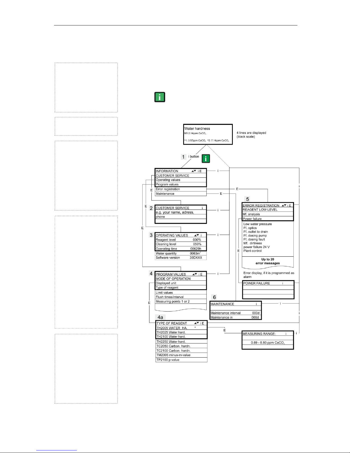
Information menu "i"
42
Information menu "i"
In the information menu, it is possible to request active settings and
statuses of the instrument, the error history, the date for the next
maintenance and the customer service address.
Call (1)
Use the key to open the information menu "i".
Request options: Customer service, operating values, program
values, error history, maintenance
Please refer to the section "Password protection and basic
programming" for further programming and setting details for the
individual menu items
Operating values (3)
Display of current values.
Program values (4)
Use the arrow buttons to call
the menu item "Program
values". Press "ENTER" to
open the list of set values. The
current setting of a parameter
can be requested via "ENTER",
An asterisk indicates the
selected functions. (There are
no active lines)
Error history (5)
Use the "i" and "ENTER" keys
to open the error history. The
error history is a list of errors or
statuses which have occurred
during operation. The list is
deleted after a power failure
and a new list is started.
If no errors have occurred
since start-up, the last switchon time of the unit is displayed,
e.g.:
POWER FAILURE
from 16.06.09 06:56
to 16.06.09 07:09
Maintenance (6)
Display of the next
maintenance date and the
programmed maintenance
interval. It is possible to set the
maintenance interval in the
basic program (password
protected).
Refer to the section entitled
"Maintenance" for further
details on maintenance
intervals.
Customer service (2)
Display of the customer service
address or, e.g., a service
hotline.
You can freely program these
lines in the basic program
(password protected).
Page 43
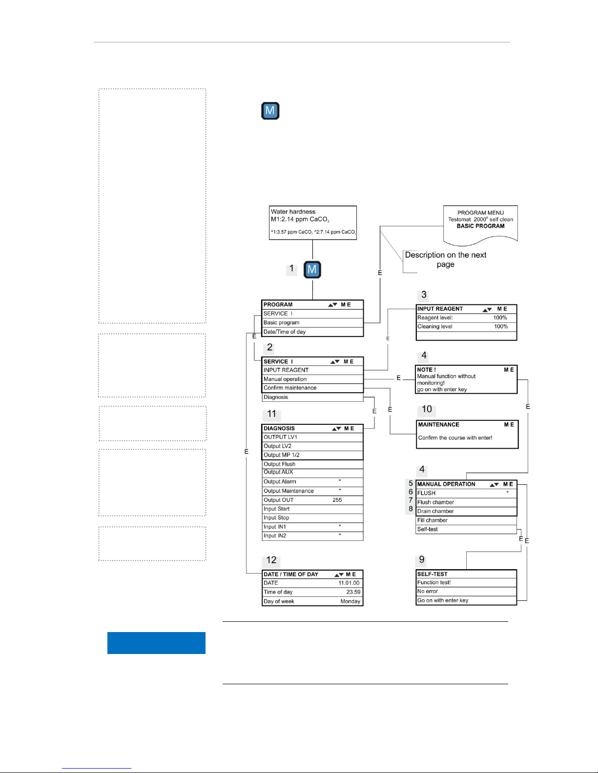
Program menu "M"
43
Program menu "M"
Call: (1)
Use the key to open the program menu "M".
It is possible to call up all the functions without password protection
except for the basic program.
Programming of: Indicator, manual mode, flushing, flush chamber,
drain chamber, fill chamber, self-test, confirm maintenance,
diagnosis, date, time, basic program with password
Availability of functions
All manual functions can only be selected during an analysis pause.
Analyses are not carried out during manual operation. All signal
inputs and outputs are locked.
Fill chamber (8)
Press the "ENTER" key to fill
the measuring chamber.
Flush chamber (6)
Press the "ENTER" key to flush
the measuring chamber once.
Drain chamber (7)
Press the "ENTER" key to open
the outlet valve in order to drain
the water from the measuring
chamber. Press the "ENTER"
key again to cancel this
function.
Service I (2)
Input indicator (3)
Enter the new filling levels after
each refill or indicator bottle
change. Once you have
selected the menu item for
entering the filling level
"Reagent level: (0 - 100%)" via
the "ENTER" key, the value is
preset to 100%. If you have
connected a full bottle, press
"ENTER" to confirm the value.
If the filling level of the bottle
differs, enter the corresponding
value.
Manual operation (4)
After confirming the information
message (4) via the "ENTER"
key, it is possible to select and
activate the desired function by
using the arrow keys and
pressing the "ENTER" key.
These functions are used for
checking the functions and for
commissioning.
Flush (5)
Start the flushing of the
sampling tube through the
internal valve by pressing
"ENTER". When "ENTER" is
pressed again, this function is
terminated.
NOTE
Page 44
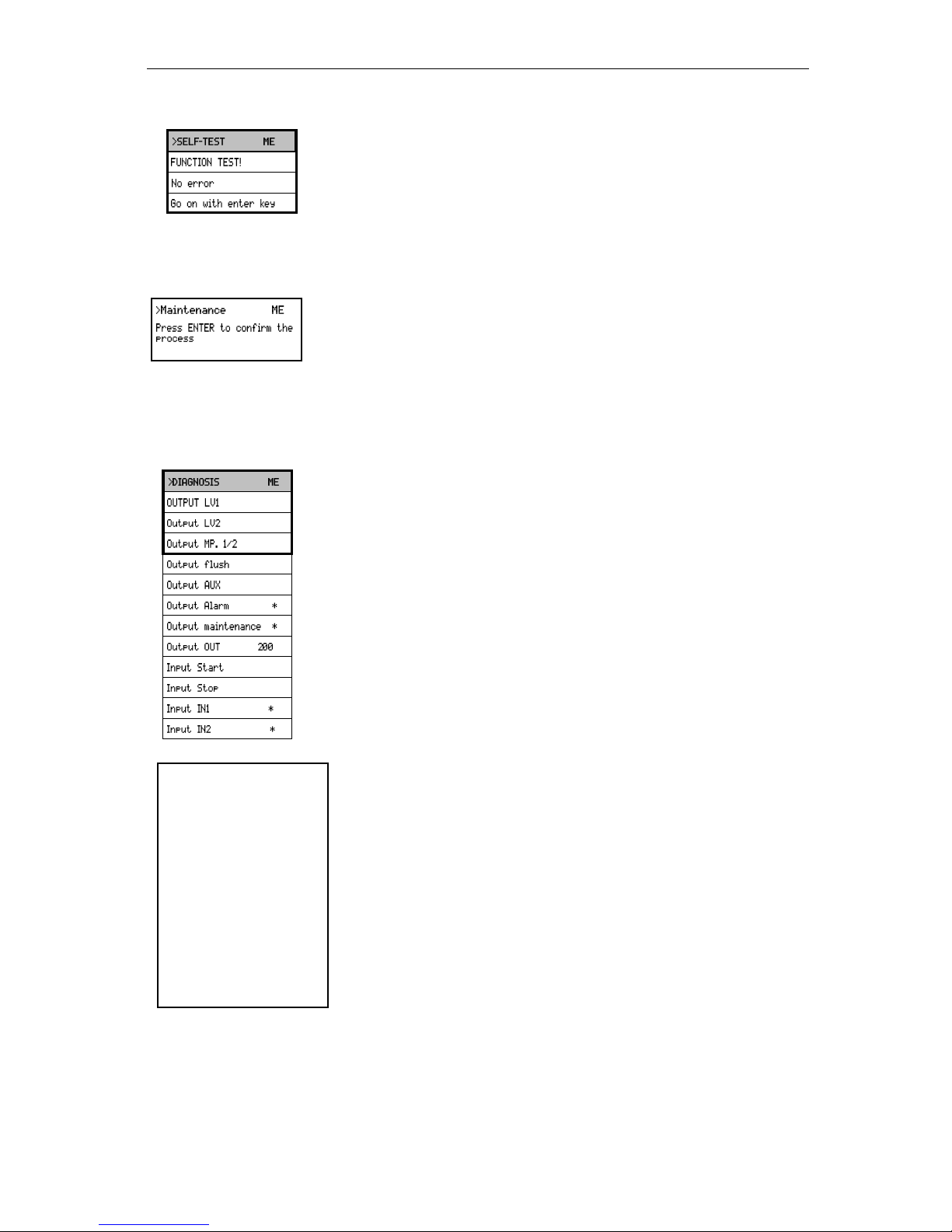
Program menu "M"
44
Self-Test (9)
Press "ENTER" to start the functional test of Testomat 2000®. The
program checks all relevant instrument functions and carries out an
analysis. A respective message appears after an error-free test.
Press the "ENTER" key again to cancel this function and to return to
the "MANUAL MODE" menu.
Confirm maintenance (10)
After maintenance has been carried out, confirm it by pressing the
"ENTER" key and exit this item via the "M" key. The maintenance
interval is restarted.
Confirm a maintenance request once the maintenance interval has
expired in the M menu. The displayed message is deleted and the
“maintenance” output reset.
Refer to the section entitled "Maintenance" for further details on
maintenance intervals.
Diagnosis (11)
It is possible to request a list of current statuses of the signal inputs
and outputs. Active statuses are marked with an *. (see "Structure of
the basic program").
The current interface can be checked under the "OUT output". Press
the "Enter" key to toggle between minimum and maximum current.
000 and 200 are alternately shown on the display for 0-20 mA!
Time/Date (12)
Set the time and date by selecting and activating the desired function
via the arrow keys and the "ENTER” key. Subsequently press the "M"
key again to save the setting and to return to the display function.
Refer to "Functions of the operating and display elements"
"Operating system" for more details.
Basic program
This menu item can only be accessed after entering the password!
After entering the password and confirming it via the "ENTER" key, it
is possible to carry out basic programming of the instrument and to
select various service functions (e.g. calibration).
In the basic program, the following abbreviations are used in the
respective menu items:
s = seconds; m = minutes; h = hours; T = days; l = litre
▼▲
▼▲
Call the factory
default setting:
Press the "M" and "i" key
and switch on Testomat
2000®.
Caution: All previously
entered data is
overwritten!
The values and settings
of the basic default
setting are described in
the "structure of the
basic program".
Page 45
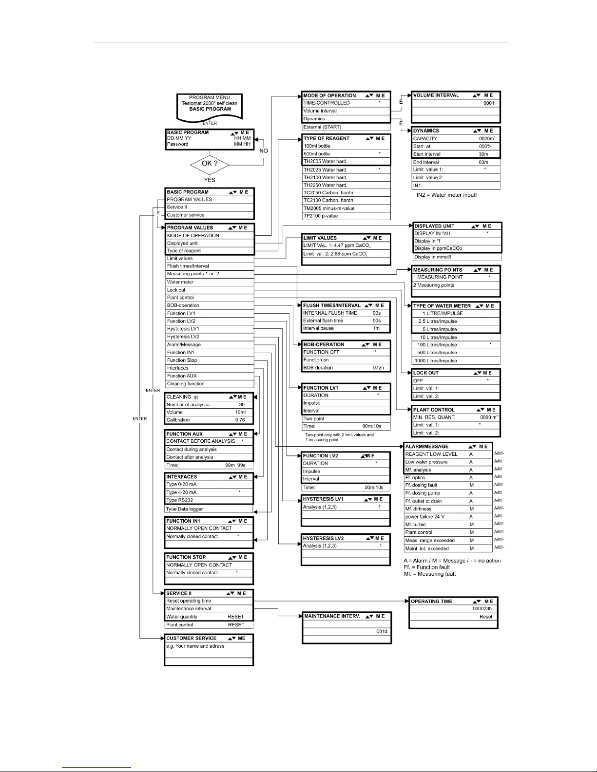
Program menu "M"
45
Structure of the basic program
Call the basic factory program by simultaneously pressing and holding down the "M" and "i" keys
while switching on the instrument. CAUTION, the last set of programming will be erased!
Page 46
Error messages/Troubleshooting
46
Error messages/Troubleshooting
Displayed message (flashes at
selected display)
Instrument result functions
Possible causes
Remedies
Ff. POWER FAILURE 24 V
CANCEL WITH HORN KEY
- After programming:
Continuous alarm or message
impulses
- Standby
- Internal power failure of the
24 V supply
Replace fuse F4 or F8
(The control lamp "Power"
of the dosing pump should
illuminate)
Ff. DOSING PUMP
CANCEL WITH HORN KEY
- After programming:
Continuous alarm or message
impulses
- Standby
- Dosing pump is defective
- No dosing message from
the dosing pump
Replace dosing pump
Check cable to the dosing
pump for correct
connection
Mf. TURBID
CANCEL WITH HORN KEY
- After programming:
Continuous alarm or message
impulses or no message
- Continue measurements
- The water is turbid / soiled
MEASURING RANGE EXCEEDED
CANCEL WITH HORN KEY
- After programming:
Continuous alarm or message
impulses or no message
- Continue measurements
- The measuring range has
been exceeded
Select another type of
indicator (basic program)
LOW WATER LEVEL
CANCEL WITH HORN KEY
- After programming:
Continuous alarm or message
impulses
- Standby
- No water input although
LED "IN" lamp illuminates
- Inlet pressure too low
- Overflow detection does not
react
Check water inlet
Connector at the inlet
valve oxidised
Clean filter strainer
Replace valve block
Extract flow controller
valve body
Replace fuse F6
Ff. OUTLET TO DRAIN
CANCEL WITH HORN KEY
- After programming:
Continuous alarm or message
impulses
- Standby
- Water remains in the
measuring chamber
although LED "OUT"
illuminates
Check water outlet
Connector at the outlet
valve oxidised
Replace valve block
LOW INDICATOR LEVEL
CANCEL WITH HORN KEY
- After programming:
Continuous alarm or message
impulses or no message LED
and output "maintenance" on
- Continue measurements
- Minimum indicator quantity
not reached
Without BOB: 50 ml (10%),
With BOB: According to
calculation
Check indicator level and,
if necessary, refill
(enter the filling quantity!)
Mf. SOILING
CANCEL WITH HORN KEY
- After programming:
Continuous alarm or message
impulses or no message LED
and output "maintenance" on
- Continue measurements
- Sight-glass windows are
soiled
Clean sight-glass windows
Ff. OPTICS
CANCEL WITH HORN KEY
- After programming:
Continuous alarm or message
impulses
- Standby
- Plug-in circuit board
defective
- Error at the optical
component (transmitter or
receiver defective)
Replace plug-in circuit
board
Replace the measuring
chamber holder
Abbreviations: Ff.: = function fault, Mf. = Measuring fault
Page 47
Error messages/Troubleshooting
47
Displayed message (flashes at
selected display)
Instrument result functions
Possible causes
Remedies
Mf. ANALYSIS
CANCEL WITH HORN KEY
- After programming:
Continuous alarm or message
impulses
- Standby
- Air inside the dosing hoses
- Incomplete mixing
- Indicator out of date or use
of a third-party indicator
Retighten dosing pump
connections
Replace intake insert in
the bottle
Replace stirring bar
Replace indicator, only
use HEYL Testomat®
2000 indicator
Ff. DOSING ERROR
CANCEL WITH HORN KEY
- After programming:
Continuous alarm or message
impulses or no message
- LED and output
"maintenance" on
- Continue measurements
- Dosing accuracy of the
dosing pump
Replacing dosing pump or
return it for calibrating
MAINTENANCE INTERVAL
EXCEEDED BY
XXX DAYS
CANCEL WITH HORN KEY
- After programming:
Continuous alarm or message
impulses or no message
- LED and output
"maintenance" on
- Continue measurements
- Programmed maintenance
date reached or exceeded
Carry out maintenance
and subsequently cancel
or confirm
Abbreviations: Ff.: = function fault, Mf. = Measuring fault
Further information
Error
Possible causes
Remedies
Current interface functions incorrectly
- Incorrect measured value at the output or
no power supplied
Replace fuse F7
Replace the interface circuit board
Unit is not functioning, even though it is
switched on
No display
- Fuse F9, F5 or F2 (240 V: F1) defective
- Power switch defective
- Ribbon cable at display circuit board or
base circuit board is loose
- Error at display circuit board or base
circuit board
Replace fuses
Replace power switch
Reconnect ribbon cable
Replace display or base circuit board
Tripping of a protective circuit
After a protective circuit (fuse) has been tripped, attempt to eliminate
the cause of malfunctioning (e.g. replace a defective valve) before
reactivating the protective circuit. Frequent triggering is always due to
power overload which, in certain circumstances, may also damage to
the instrument.
Malfunctioning/Repairing a defective instrument
The repair of a defective instrument – irrespective of the warranty
period – is only possible when the instrument is dismantled and
returned to us with a description of the error. Furthermore, please
inform us of the indicator type being used and the measured medium.
Before you return the instrument for repair work, remove the bottle
and ensure that the measuring chamber has been flushed out and is
empty.
Page 48
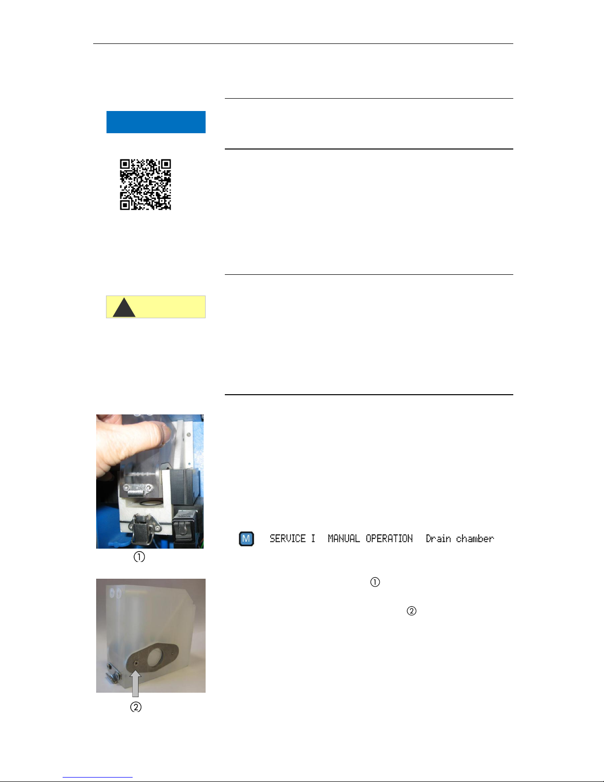
Maintenance
48
Maintenance
Required maintenance measures
Regular maintenance is necessary to ensure trouble-free operation of
the instrument!
Please regularly carry out the maintenance work described in the
following section when
the programmed maintenance date has been reached (display
"maintenance interval exceeded")
the instrument displays the following error messages:
"Mf. dirtiness" or "Low Reagent low level"
the last maintenance was carried out max. 6 months ago
Cleaning measures
Never use organic solvents to clean the measuring chamber or other
plastic parts!
Please observe the safety regulations when handling cleaning
agents!
If the measuring range of the instrument is exceeded over a longer
period of time, a coloured film may form on the sight-glass windows.
Use alcohol to remove this sticky film.
Description of maintenance work
The maintenance manual Testomat 2000®/Testomat ECO® contains
a detailed description of maintenance work. The measures described
here provide a brief overview.
Cleaning the measuring chamber and sight-glass windows
Switch off the instrument or press the "STANDBY" key. If required,
remove any water from the measuring chamber:
Close the manually-operated valve of the branch line to Testomat
2000®.
Unhook the toggle type fastener , tip the measuring chamber
upwards and remove it.
Release both sight-glass window holders , remove and clean the
sight-glass windows.
Use alcohol to clean off the film on the sight-glass windows. If the
instrument has been used with hard water for a longer period of
time (measuring range exceeded!), a hard-to-remove film may
have formed on the sight-glass windows. In this case, clean the
sight-glass windows as described below for cleaning the
measuring chamber.
CAUTION
!
Scan the code to
download the latest
service manuals!
NOTE
Page 49
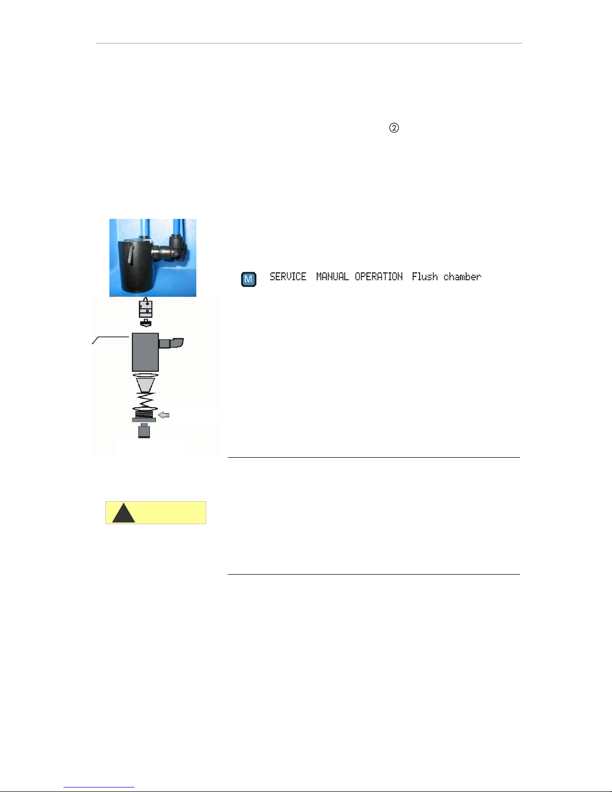
Maintenance
49
The measuring chamber can be cleaned with a cleaning agent
suitable for decalcification and rust removal. Flush the measuring
chamber thoroughly after cleaning.
After cleaning, re-insert the sight-glass windows and secure them
with the sight-glass window holders . (Do not forget the flat
seals, making sure they are fitting correctly in the groove).
Re-insert the measuring chamber and use the toggle type fastener
to secure it.
Cleaning the filter housing
Close the manually-operated valve of the branch line to Testomat
2000®.
Depressurise the lines of Testomat 2000® via the “Flush” function:
Switch of the instrument and loosen the hose connections at the
filter housing.
Unscrew the inlet connection using an open ended spanner (size
22) and remove the seal, spring and filter.
Remove the retaining pin and extract the flow controller,
subsequently remove the flow controller valve body.
Clean the filter housing with water or alcohol; then reassemble the
unit.
If required, replace the seals.
Insert the filter strainer with the cone facing downwards!
Re-attach the hose connections at the filter housing.
Important maintenance information
Water leakage at sealed points can damage parts of the
instrument!
Please check the instrument for leaks prior to the first analysis.
Switch the instrument to STANDBY
Manually fill the measuring chamber
Manually dose the indicator ("Manual" key)
Check the connections and seals for leaks
Service instructions
The surface of the instrument has not been treated. Therefore, soiling
caused by indicators, oil or grease should be avoided. However, if the
housing becomes soiled, please clean the surface with isopropanol
(never use other solvents).
Zulaufanschluss
Inlet connector
Regler-/Filteraufnahme
Regulator/filter
CAUTION
!
Page 50
Testomat 2000® spare parts and accessories
50
Testomat 2000® spare parts and
accessories
Art. no.
Pressure controller
40125
Controller / Filter receiver, complete
40120
Controller / Filter receiver
40129
Controller plug T2000, complete
11225
Flow controller valve body
11230
Retaining pin 3x38
11217
Inlet filter
11218
Spring for inlet filter
40121
Inlet connector
40153
Screw-in connector G 1/4" -6
40157
Angled plug-in connector G 1/8"
Measuring chamber
40173
Sight-glass window with seal
40170
Sight-glass window 30x3
40176
Sight-glass holder
33253
Bolt M3x40
40032
Latch fastener TL-17-201-52
11210
Plug for measuring chamber
40022
Measuring chamber T2000 complete.
Measuring chamber holder
40029
Measuring chamber holder, complete
(without valves)
40050
Magnetic stirrer
40186
Screw-in connector 3/8" -10
40018
Solenoid valve, 2/2-way
40181
Rear guide bar for measuring chamber
5x60
Dosing pump DOSIClip®
40001
Jet pump SP
40011
Hose, suction, complete
40016
Hose, pressure, complete
37232
Base circuit board TI
40040
Valve set
32046
Plastic cover CNH 45 N
Dosing pump FLOWClip
40224
Membrane pump FLOWClip kpl.
Bottle connection/Suction device
40131
Screw cap with bottle insert T2000
40130
Screw cap GL32 - hole
40135
Bottle insert for screw cap with push-fit
suction tube
Art. no.
Instrument spare parts
31582
Fuse M4A
40294
Base circuit board T2000 complete
230 V
40092
Control circuit board T2000 complete
40091
Plug-in circuit board driver/receiver SET2000 (6)
40190
Cable gland 5-7
40191
Cable gland 7-10
31713
Ribbon cable 10 pole with EMI filter
clamp
40096
Ribbon cable 26 pole with EMI filter
clamp
40060
Cable loom 2V complete (for valves)
40062
Cable loom 2P complete (for max. 2
dosing pumps)
40200
Cable loom complete with mains switch
and cap
31596
Fuse T0.08A
31585
Fuse T0.315A
31595
Fuse T0.1A
31622
Fuse T0.16A
31592
Fuse T1.0A
Spare parts requirements for 2 - 3 years of
operation
40173
Sight-glass window with seal
11217
Inlet filter
40124
Gasket set T2000 (according to
maintenance requirements)
31585
Fuse T0.315A
31592
Fuse T1.0A
Page 51
Testomat 2000® spare parts and accessories
51
Accessories
Indicator type
Measuring ranges
Art. no.
TH2005
Water hardness 0.05 – 0.5 °dH
152005
TH2025
Water hardness 0.25 – 2.5 °dH
152025
TH2100
Water hardness 1.0 – 10.0 °dH
152100
TH2250
Water hardness 2.5 - 25 °dH
152250
TC2050
Carbonate hardness
153050
TC2100
Carbonate hardness
153100
TM2005
Minus m-value
154005
TP2100
p-value
155100
Cleaning solution
151105
Please refer to our delivery programme for an up-to-date overview of
available accessories.
*) Retrofit kit for water inlet (Art. no. 040123)
If fabric-reinforced pressure hoses (e.g. for existing installations) are
used, please replace the plug connector at the controller and filter
housing with a plug for the quick-release coupling (not included).
Art. no.
Description
040123
Retrofit kit for water inlet *)
040315
Discharge hopper for Testomat 2000/ECO
270305
Current interface card 0/4 - 20 mA, SK 910
270310
RS-232 interface card for log printer, RS 910
270315
Voltage interface card 0/2 - 10 V, UK 910
100490
SD-Card Data Logger for Testomat 2000
270500
Log printer
270501
Power supply unit for log printer
270410
Booster pump
270335
Maintenance case T2000 Heyl
Page 52
Technical data
52
Technical data
Power supply:
230 VAC, 115 VAC or 24 VAC ± 10%, 50 60 Hz
Instrument fuse 230 V: T0,1 A
Instrument fuse 115 V: T0,2 A
Instrument fuse 24 V: T1,0 A
Power consumption:
max. 30 VA, without external load
Protection class:
I
Degree of protection:
IP 65
Conformity:
EN 61000-6-2, EN 61000-6-4,
EN 61010-1
Ambient temperature:
10 – 45 °C
Measuring range:
See section "Performance specifications"
Current interface:
0/4 - 20 mA, max. load 500 Ohms
Log printer:
See section "Accessories"
Dimensions:
W x H x D = 380 x 480 x 280 mm
Weight:
Approx. 9.5 kg
Other:
The instrument is non-volatile
Water connection
Operating pressure:
1 to 8 bar / 1x10⁵ to 8x10⁵ Pa
or
0.3* to 1 bar / 0.3x10⁵ to 1x10⁵ Pa
(Remove flow controller valve body 11225! )
Water inlet:
Opaque pressure hose with external
diameter 6/4x1 mm
Water outlet:
Pressure hose with internal diameter 12
mm
Water temperature:
10 to 40 °C
* When using Testomat 2000® at a pre-pressure of 0.3 bar, it must
be ensured that the flow rate through the measuring chamber is at
least 400 ml/min.
We reserve the right to make technical changes without notice in
the interest of constantly improving our products!
Our manuals are updated regularly. If you have an older version
(see version at the back of the manual) you will find the current
manual on our website www.heyl.de on the download page.
Page 53

Technical data
53
Conformity Declaration
Page 54
Check List Testomat 2000®
Dear customers and service technicians,
This check list cannot replace your expertise or extensive experience in fault resolution. It is intended to support fast and systematic error diagnosis
and error documentation. This list does not claim to be complete. We are therefore always grateful for any advice and information you may be able
to provide. General user instructions can be found on the rear of this check list.
The Instrument Manufacturer
Block 1 / Plant and instrument data
Testomat 2000®
Testomat® ECO
Plant type
Instrument type
Instrument no.
Indicator type
Software status
Pump no.
Block 2 / Error message and error history Please mark appropriately (X)
What does your instrument’s error history display?
(“i” and “Enter” key => operating instructions)
( Error history text )
Does an error message appear on the display?
For example, “Mf. analysis”, “Low water level”, etc.
(See operating instructions: “Error messages /
Troubleshooting”)
Yes No
( Error message text )
Block 3 / Visual inspection and functional test Please mark appropriately (X) If applicable, values / comments
Is the instrument connected to the mains voltage specified on the rating plate?
Yes No
Does a message appear on the display?
Yes No
Does the instrument display a plausible measured value?
(possible manual measurement ___________ value)
Yes No
Measured value:
Are the measuring chamber and sight-glass windows clean?
Yes No
Are the measuring chamber and the water-carrying hoses free of leaks?
Yes No
Is the indicator’s expiry date still valid?
(See expiry date printed on the indicator bottle)
Yes No
Expiry date:
Has the correct indicator type been programmed?
(TH 2025 => 0.25 to 2.5 °dH = factory setting)
Yes No
Type:
Is the water pressure within the specified range (400 ml/min)?
(See the type plate on the instrument)
Yes No
Plant pressure:
Does the drain hose prevent the risk of backwater?
(No “syphoning effect”!!)
Yes No
Is the drain hose free of blockages?
(Microorganisms caused by contamination, etc.)
Yes No
Does the set flushing time/quantity of flush water ensure that only freshwater
is measured?
Yes No
Flushing time:
Are the hoses at the dosing pump free from air bubbles?
(Operate the pump manually / Carry out a manual analysis)
Yes No
CARRYING OUT A (MANUAL) ANALYSIS
Does the water column rise evenly up to the overflow borehole when filling the
measuring chamber (5 mm below the upper edge of the measuring chamber)?
(If not: check the water pressure, water throughput/flow controller)
Yes No
Does the indicator pump dose correctly when starting an analysis?
(LED at the pump illuminates!)
Yes No
No. of dosing strokes:
Have the indicator and water been mixed properly in the measuring
chamber after the dosing process?
Check the magnetic stirring bar! =>see maintenance manual “Adjust mode”
Yes No
PROGRAMMING DATA / OPERATING CONDITIONS
Have the limit values been set correctly? (Within the measuring
range/according to the performance limit of the plant?)
Yes No
Limit values:
Is the Testomat instrument always supplied with mains voltage – except
during maintenance work/emergency situations?
(Temporary shutdown only via the “Standby” key or the “Stop” input!)
Yes No
See the “General instructions for
operating Testomat 2000® and
Testomat® ECO”
Please refer to “Error messages / Troubleshooting” in the operating instructions for further information on error messages and possible causes
of faults.
Further functional tests (e.g. overflow detection and amplification setting => “Special function Adjust mode”) and service instructions can be found
in the maintenance manual.
After completing these checks, experience shows that it can be assumed that the checked functions (Block 3) are in effective working order if you
have answered all the questions with “Yes”. We recommend you to carry out these checks during each inspection or if faults occur.
Page 55
Technical data
Instrument settings
Caution!
Your settings may be deleted if repairs are carried out. Therefore, note down your instrument settings in the table below before
sending the instrument to our service team for repairs. Please enclose a copy of the table with the instrument. If you have noted
down the settings, they can be easily re-entered by your service staff once any repairs have been completed.
Menu
Setting
MODE OF OPERATION
Time-controlled
Volume interval
Dynamics
External (Start)
DISPLAY UNIT
Display in °dH
Display in °f
Display in ppm CaCO3
Display in mmol/l
TYPE OF REAGENT
500ml-bottle
100ml-bottle
TH2005 Water hard.
TH2025 Water hard.
TH2100 Water hard.
TH2250 Water hard.
TC2050 Carbon. hardn.
TC2100 Carbon. hardn.
TM2005 minus-m-value
TP2100 p-value
LIMIT VALUES
Limit val. 1:
Limit val. 2:
FLUSH TIMES/INTERVAL
Internal flush time
External flush time
Interval pause
MEASURING POINTS
1 Measuring point
2 Measuring points
TYPE OF WATER METER
1 Litre/Impulse
2,5 Litres/Impulse
5 Litres/Impulse
10 Litres/Impulse
100 Litres/Impulse
500 Litres/Impulse
1000 Litres/Impulse
LOCK OUT
Off
Limit val. 1:
Limit val. 2:
PLANT CONTROL
Min. Res. Quant.
Limit val. 1:
Limit val. 2:
BOB-OPERATION
Function off
Function on
BOB-duration
FUNCTION LV1
Duration
Impulse
Interval
Two point
Time:
FUNCTION LV2
Duration
Impulse
Interval
Time:
HYSTERESIS LV1
Analysis (1,2,3)
HYSTERESIS LV2
Analysis (1,2,3)
ALARM/MESSAGE
Reagent low level
Low water pressure
Mf. analysis
Ff. optics
Ff. dosing fault
Ff. dosing pump
Ff. outlet to drain
Mf. dirtiness
power failure 24 V
Mf. turbid
Plant control
Meas. range exceeded
Maint. int. exceeded
FUNCTION IN1
Normally open contact
Normally closed contact
FUNCTION STOP
Normally open contact
Normally closed contact
INTERFACES
Type 0-20 mA
Type 4-20 mA
Type RS232
Type Data logger
FUNCTION AUX
Contact before analysis
Contact during analysis
Contact after analysis
Time:
OPERATING TIME
MAINTENANCE INTERV.
CUSTOMER SERVICE
Page 56
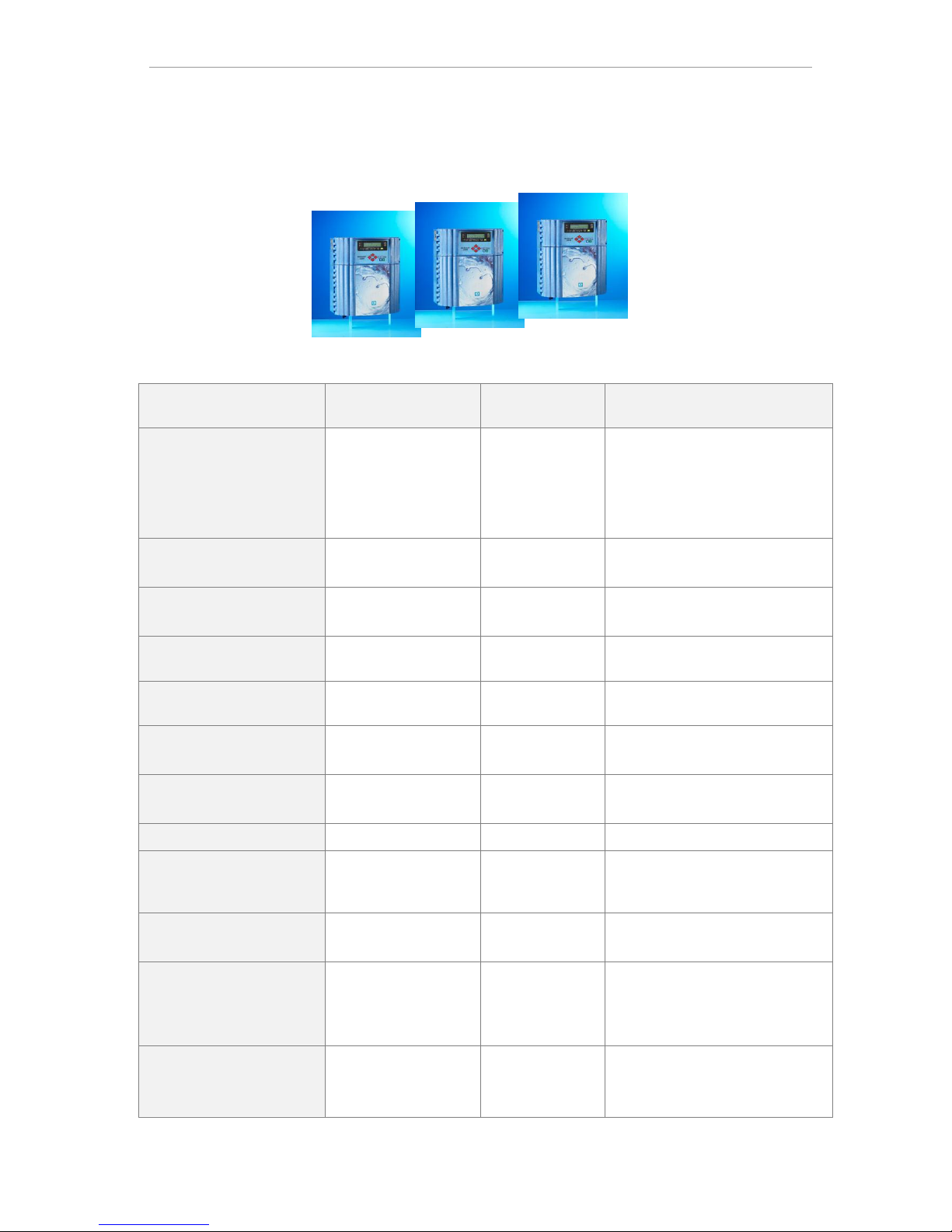
Product overview Testomat 2000®-Instruments
56
Product overview Testomat 2000®-Instruments
Model/Type
Measuring
Parameter
Measuring
Range
Applications/Functions
Testomat 2000®
• Water hardness
• Carbonate
hardness
• p-value
• minus-m-value
0.05-25 °dH
0,5-20 °dH
1-15 mmol/l
0.05-0.5 mmol/l
• Universal for water treatment
plants
• allowed for boiler houses
Testomat 2000® Antox
as
Testomat 2000®
as
Testomat 2000®
• dosing a reducing agent
Testomat 2000® CAL
as
Testomat 2000®
as
Testomat 2000®
• Automatic calibration function
Testomat 2000® CLF
• Free Chlorine
0-2.5 mg/l
• DPD-method for swimming
pool and drinking water control
Testomat 2000® CLT
• Total Chlorine
0-2.5 mg/l
• DPD-method for swimming
pool and drinking water control
Testomat 2000® CrVI
• Chromate
• Chrome-VI
0-2.0 mg/l
0-1.0 mg/l
• process control of waste water
in galvanic industry
Testomat 2000® Duo
as
Testomat 2000®
as
Testomat 2000®
• Controlling of two measuring
points
Testomat 2000
®
Fe
• Iron-II and Iron-III
0-1.0 mg/l
• De-Ironing plants
Testomat 2000
®
SO3
• Sulphite
0-20 mg/l
• Control of the Oxygen-binding
by Sulphite in boiler feed
water
Testomat 2000
®
self clean
as
Testomat 2000®
as
Testomat 2000®
• Automatic cleaning of the
measuring chamber
Testomat 2000 THCL®
• Total Chlorine
• Water hardness
0-2.5 mg/l
0.25-2.5 °dH
• DPD-method for swimming
pool and drinking water control
• combination system for
hardness and chlorine
Testomat 2000
®
V
• Water hardness
• Carbonate
hardness
1.0-25.0 °dH
1.0-20.0 °dH
• blending water
Page 57

57
Page 58
58
Gebrüder Heyl
Analysentechnik GmbH & Co. KG
Orleansstraße 75b
D 31135 Hildesheim
www.heyl.de
Testomat_2000_selfclean_GB_140929.doc
Scan the code and
visit us on our website!
 Loading...