

Page 1
HEARTH PRODUCTS
KITS AND ACCESSORIES
775,253M
Rev. A, 06/2010
INSTALLATION INSTRUCTIONS FOR INSTALLING ARCH AND CLASSIC FACE KITS
FOR USE WITH THE RAVELLE 30 AND RAVELLE 42 DIRECT VENT GAS FIREPLACES
KIT CONTENTS (See Figure 1):
Please ensure that all these parts are in one of the two boxes.
See complete list of kits available on Page 4.
1 ea. Face, (Large box) Item #1
1 ea. Insets (Two insets in small box), Item #2
2 ea. Mounting brackets (Included in large box) Item #3
1 ea. Bolt Kit (Includes 2- lower mounting screws and
14 ea. 10/24 nuts) (Included in large box) Item #4
1 ea. Instruction Sheet
TOOLS NEEDED:
3/8” Nutdriver or Wrench
Phillips Screwdriver
Arch Face Required to
Complete Face: Insets
RAVELLE 30
Cat. No.
75286 75294 Black Face
75288 75296 Gold Face
75287 75295 Brushed Nickel Face
75289 75297 Black Nickel Face
Insets - Required,
Includes 1 Top &
1 Bottom Inset)
RAVELLE 30
Cat. No.
75306 75322 ASPEN Black
75308 75324 ASPEN Gold
75307 75323 ASPEN Brushed Nickel
75309 75325 ASPEN Black Nickel
75330 75338 NAPA Black
75332 75340 NAPA Gold
75331 75339 NAPA Brushed Nickel
75333 75341 NAPA Black Nickel
75298 75314 TUSCAN Black
75300 75316 TUSCAN Gold
75299 75315 TUSCAN Brushed Nickel
75301 75317 TUSCAN Black Nickel
RAVELLE 42
Cat. No.
RAVELLE 42
Cat. No.
Description
Aspen™
Napa™
Tuscan™
Description
NOTE: DIAGRAMS AND ILLUSTRATIONS ARE NOT TO SCALE.
Classic Face Required to
Complete Face: Insets
RAVELLE 30
Cat. No.
75282 75290 Black Face, Classic
75284 75292 Gold Face, Classic
75283 75291 Brushed Nickel Face, Classic
75285 75293 Black Nickel Face, Classic
Insets (Required Includes 1 Top &
1 Bottom Inset)
RAVELLE 30
Cat. No.
75310 75326 ASPEN Black
75312 75328 ASPEN Gold
75311 75327 ASPEN Brushed Nickel
75313 75329 ASPEN Black Nickel
75302 75318 NAPA Black
75304 75320 NAPA Gold
75303 75319 NAPA Brushed Nickel
75305 75321 NAPA Black Nickel
75334 75342 TUSCAN Black
75336 75344 TUSCAN Gold
75335 75343 TUSCAN Brushed Nickel
75337 75345 TUSCAN Black Nickel
Item #3
Item #4
Figure 1 - Kit Contents
ARCH AND CLASSIC FACE AND INSET KITS
MODELS RAVELLE™ 30 AND RAVELLE 42
RAVELLE 42
Cat. No.
RAVELLE 42
Cat. No.
Item #1
Item #2
Description
Aspen
Napa
Tuscan
Description
TM
1
Page 2
GENERAL INFORMATION
All of these parts may scratch and bend, great care should be used
in handling them.
If you encounter any problems, need clarification of these instructions
or are not qualified to properly install this kit, contact you local distributor or dealer.
Read this instruction sheet in its entirety before beginning the installation.
ALL WARNINGS AND PRECAUTIONS IN THE INSTALLATION AND
OPERATION MANUAL PROVIDED WITH THE APPLIANCE APPLY TO
THESE INSTRUCTIONS.
TURN OFF THE FIREPLACE AND ALLOW IT TO COMPLETELY COOL
BEFORE PROCEEDING.
INSTALLATION INSTRUCTIONS
Step 1. Remove the face from the box (item #1 in Figure 1) and place
the face down making sure that the side with the studs are facing upwards. Be sure that the front of the face is lying on a soft
non-abrasive surface to avoid any scratches to the surface of the
face.
Step 2. Remove the insets from it’s box (item #2 in Figure 1). If you have
chosen a brushed nickel, black nickel or gold insets there will be
blue protective tape on the side that will be directed towards the
front of the appliance or facing away from you as you are doing
this procedure. If you have chosen black insets either side can
face the front of the face. Make sure the upper and lower inset
patterns are facing the same direction so they appear the same
when the face is installed on the unit.
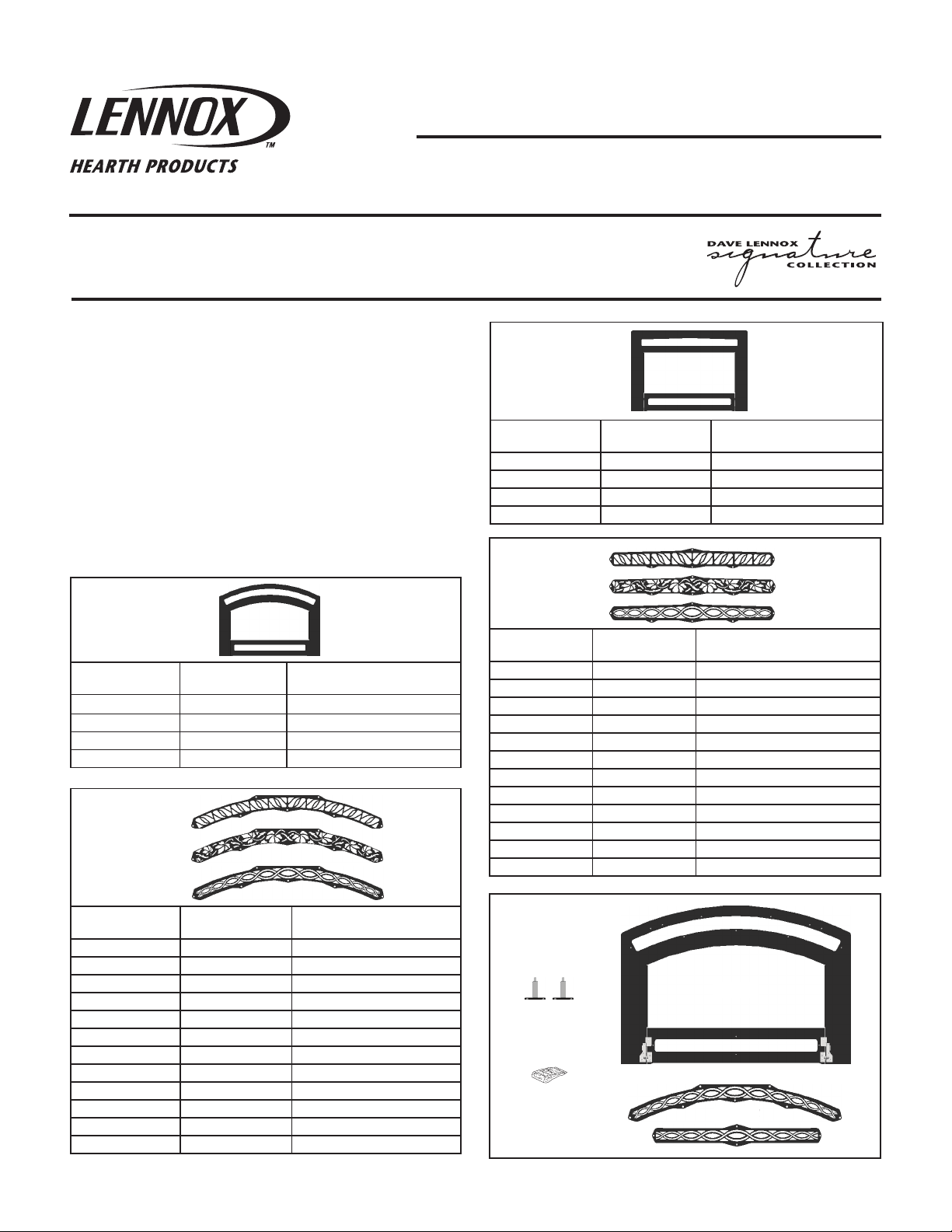
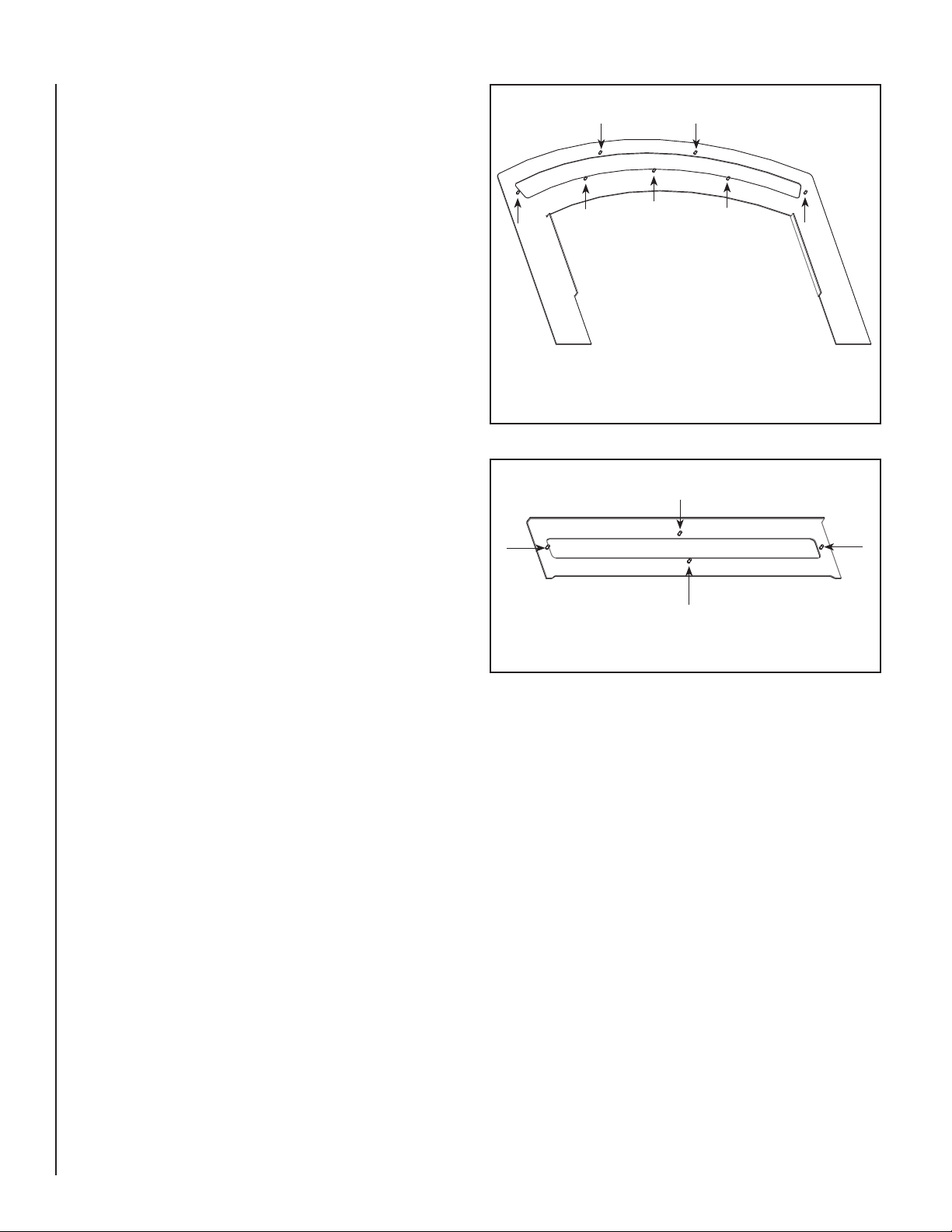
Step 3. Next place the classic or arched insets holes over the studs along
the top and the bottom designated studs. There are six studs on
the top of the face to mount the top inset, and there are 4 studs
on the bottom of the face to mount the bottom inset (See Figure 2
for top stud location and see Figure 3 for bottom stud location).
The nuts to fasten the insets to the face can be found in the box
the face came in.
VERY IMPORTANT: SCREW THE NUTS ONTO THE STUDS “FINGER
TIGHT” ONLY. MAKE SURE THE FACE AND THE INSETS ARE NOT
BOWED BEFORE TIGHTENING. THEY MUST BE STRAIGHT BEFORE THE
INSETS ARE SECURED TO THE FACE. AFTER FINGER TIGHTENING THE
NUTS YOU MAY NOW SNUG THE NUTS SLIGHTLY. OVER-TIGHTENING
THE NUTS WILL RESULT IN DAMAGING THE STUDS AND THE FACE.
Figure 2 - Stud Locations on Top of Face
Figure 3 - Stud Locations on Bottom of Face
2
NOTE: DIAGRAMS AND ILLUSTRATIONS ARE NOT TO SCALE.
Page 3

Step 4. Included in the face box are two mounting brackets that attach to
the top of the face. There is a left and a right hand bracket. When
the bracket is installed on the face the lower left hand corner of
the bracket will have an angled edge that will be facing towards
the outside of the face. The mounting brackets for the Ravelle™
30 Arch face uses the smaller brackets with a measurement of
2 inches across the top (See Figure 4B, item #1). The mounting
brackets you will use for the Ravelle 30 Classic face will be the
longer brackets with a measurement of 3-1/2 inches across the
top (See Figure 4B, item #2). Place the correct bracket onto the
studs shown in Figure 5. Thread nuts onto the studs finger tight
only (see Figure 5).
Step 5. Remove all protective film material from the face before installing
it on the fireplace. Remove any finger prints or smudges from
a plated face before burning the fireplace. They can be removed
using denatured alcohol or household glass cleaner and a soft
cloth. Marks left on these surfaces may become etched into the
finish if not removed prior to burning the unit. Never use brass
polish to clean the plated surfaces.
Note: Ravelle™ 42
Arch and Classic faces
both use the same
mounting brackets.
Ravelle 30
Arch Face Bracket
Item #1
Classic Face Bracket
Figure 4A
Item #2
Figure 4B
Nuts
Left Bracket
Right Bracket
Angled Edge to the
Outside of the Face
Figure 5
Top View of Bracket
Studs
NOTE: DIAGRAMS AND ILLUSTRATIONS ARE NOT TO SCALE.
3
Page 4

Face Installation
A number of different faces are available for the Ravelle 42 fireplace,
however all the faces are installed in a similar manner. A total of four
screws, two upper and two lower, attach the face to the fireplace. To
install the face:
Step 7. The bracket shown in Figure 7 is installed on the face during the face
assembly (see the instructions on the previous page). The captive
screws, shown in Figure 7, on this bracket need to be screwed into
captive nuts on the fireplace as follows; Align the face for plumb
and level, then using a phillips head screwdriver (inserted through
the vent holes in the face), tighten all four screws.
Step 6. Locate the two screws found in the hardware bag shipped with
the face. Position the face (with the lower door open) in front of
the fireplace. Install the two screws shown in Figure 6, through
the holes in the lower door hinge bracket and screw them into the
captive nut on the tab (see Figure 6). Do not fully tighten these
screws yet.
Captive
Nut
Tab
Screw
Expanded View
Caution: Any masonry that has been cleaned with an acid wash must be
properly neutralized before installing the fireplace face. The acid wash
will tarnish the face. Consult your masonry installer.
Two Screws
Figure 6
Captive
Screw
Captive
Nut
Bracket
Figure 7
Lennox Hearth Products reserves the right to make changes at any time, without notice, in design, materials, specifications, prices and also to discontinue colors, styles and products. Consult
your local distributor for fireplace code information.
Expanded View
Printed in U.S.A. © 2010 Lennox Hearth Products
P/N 775,253M REV. A 06/2010
4
Lennox Hearth Products
1508 Elm Hill Pike, Suite 108 • Nashville, TN 37210
 Loading...