

Page 1

Litho U.S.A.
2015
INSTALLATION
INSTRUCTIONS
WARNING
Improper installation, adjustment, alteration, ser
vice or maintenance can cause property damage,
personal injury or loss of life. Installation and ser
vice must be performed by a licensed professional
HVAC installer or equivalent or service agency.
CAUTION
Danger of sharp metallic edges. Can cause injury.
Take care and wear protective clothing when
servicing unit to avoid accidental contact with
sharp edges.
RETAIN THESE INSTRUCTIONS
FOR FUTURE REFERENCE
Table Of Contents
Dimensions Page 2.................................
Shipping and Packing List Page 3....................
General Page 3....................................
Requirements Page 3...............................
Unit Support Page 4................................
Duct Connection Page 4............................
ZHA036 (3 TON)
ZHB036 (3 TON)
ZHA048 (4 TON)
ZHB048 (4 TON)
ZHA060 (5 TON)
ZHB060 (5 TON)
HEAT PUMP PACKAGED UNITS
507111-02
2/2015
Supersedes 507111-01
Rigging Unit For Lifting Page 4.......................
Horizontal Air Discharge Page 5......................
Condensate Drains Page 5..........................
Electrical Connections Page 6.......................
Blower Operation and Adjustments Page 7............
Start-Up Page 16....................................
Defrost Control Board Page 22........................
Service Page 23....................................
ZH 036, 048, 060 PARTS ARRANGEMENT
CONTROL
PANEL
OUTDOOR
COIL FAN
COMPRESSOR
OUTDOOR
COIL
SIDE POWER
ENTRY
EVAPORATOR
COIL
BLOWER
MOTOR
BLOWER
HOUSING
ELECTRIC HEAT
(OPTIONAL)
TB2 UNIT
TERMINAL
STRIP
UNIT FUSE
BOTTOM POWER
ENTRY
Page 2

ZH 036, 048, 060, DIMENSIONS in (mm)
Holes required for Optional Bottom Power Entry Kit
BOTTOM POWER ENTRY
Conduit Fittings
(Provided in Kit)
A
B
C
Threaded
1/2
1/2
3/4
Wire
Use
ACC.
24V
POWER
47-1/4
(1200)
BASE
Hole Diameter
Required in
Unit Base (Max.)
7/8 (23)
7/8 (23)
1-1/8 (29)
16-1/8
(410)
13-5/8
(346)
11-1/8
(283)
24-9/16
(624)
BOTTOM
RETURN
AIR OPENING
A
B
C
BOTTOM
POWER
ENTRY
(See Table)
75-7/8
(1927)
12-1/8
(308)
TOP VIEW (Base)
25-5/8
(651)
BOTTOM
SUPPLY
OPENING
AIR
5-1/8
(130)
17-3/4
(451)
5-3/4
(146)
5-1/8
(130)
10-7/8
(276)
29
(737)
45-1/4
(1149)
44-7/8 (1140) ZH 060
ZHB036, 048
36-7/8 (937) ZHA036, 046
1
(25)
47-1/4
(1200)
(25)
BASE
POWER
ENTRY
1
(25)
Either
side
3-1/2
(89)
1
END VIEW
ZH 036, 048, 060
LIFTING HOLES
(For rigging)
73-3/4
(1873)
FRONT VIEW
Page 2
3-1/2 (89)
TYP.
11-7/8
(302)
5-3/4
(146)
6-1/2
(165)
CONDENSATE
OUTLET
HORIZONTAL
SUPPLY
17-3/8
(441)
27
(686)
31
(787)
END VIEW
6-1/4
(159)
RETURN
HORIZONTAL
5-9/16
(141)
8-3/8
(213)
10-7/8
(276)
25-3/4
(654)
5-3/4
(146)
Page 3

Shipping and Packing List
Package 1 of 1 contains:
1 - Assembled unit
Check unit for shipping damage. Receiving party should
contact last carrier immediately if shipping damage is
found.
General
These instructions are intended as a general guide and
do not supersede local codes in any way. Authorities
having jurisdiction should be consulted before
installation.
Availability of units and options varies by brand.
Requirements
NOTICE
Roof Damage!
This system contains both refrigerant and oil.
Some rubber roofing material may absorb oil,
causing the rubber to swell. Bubbles in the rubber
roofing material can cause leaks. Protect the roof
surface to avoid exposure to refrigerant and oil
during service and installation. Failure to follow
this notice could result in damage to roof surface.
The National Electric Code (ANSI/NFPA No. 70-1984) is
available from:
National Fire Protection Association
1 Batterymarch Park
PO Box 9101
Quincy, MA 02269-9101
The ZH unit is CSA certified as a heat pump with cooling
and with or without auxiliary electric heat for
non-residential use only at the clearances to combustible
materials as listed on the unit nameplate and in figure 1.
Installation of ZH heat pumps must conform with standards
in National Fire Protection Association (NFPA) “Standard
for Installation of Air Conditioning and Ventilating Systems
NFPA No. 90A,” “Standard for Installation of Residence
Type Warm Air Heating and Air conditioning Systems NFPA
No. 90B,” local municipal building codes and
manufacturer's installation instructions.
UNIT CLEARANCES
HORIZONTAL
OUTDOOR
AIR HOOD
C
D
A
OUTDOOR
AIR HOOD
B
Installation of CSA certified units must also conform with
current standard C273.5 “Installation Requirements for
Heat Pumps” and applicable local codes. Authorities
having jurisdiction should be consulted before
installation.
Use of this unit as a construction heater or air conditioner
is not recommended during any phase of construction.
Very low return air temperatures, harmful vapors and
operation of the unit with clogged or misplaced filters will
damage the unit.
If this unit has been used for heating or cooling of
buildings or structures under construction, the following
conditions must be met or the warranty will be void:
A room thermostat must control the unit. The use of
fixed jumpers that will provide continuous heating or
cooling is not allowed.
A pre-filter must be installed at the entry to the return
air duct.
The return air duct must be provided and sealed to
the unit.
FIGURE 1
1
Unit
Clearance
Service
Clearance
Minimum Opera
tion Clearance36(914)36(914)
*Clearance is 60 in. (1524mm) in horizontal air flow applications.
Note - Entire perimeter of unit base requires support when elevated above
mounting surface.
1
Service Clearance - Required for removal of serviceable parts.
Minimum Operation Clearance - Required clearance for proper unit operation.
A
in.(mm)Bin.(mm
36
(914)36(914)
C
in.(mm)Din.(mm)
)
36*
(914)36(914)
36*
(914)36(914)
To p
Clearance
Unob
structed
Unob
structed
Return air temperature range between 55°F (13°C)
and 80°F (27°C) must be maintained.
Air filters must be replaced and pre-filter must be
removed upon construction completion.
The unit components, duct system, air filters and
evaporator coil must be thoroughly cleaned following
final construction clean-up.
The unit operating conditions (including airflow,
cooling operation, and heating operation) must be
verified according to these installation instructions.
Page 3
507111-02 2/2015
Page 4

WARNING
Electric shock hazard and danger of
explosion. Can cause injury, death or
product or property damage. Turn off
electrical power to unit before
performing any maintenance or
servicing operations on the unit.
IMPORTANT
The Clean Air Act of 1990 bans the intentional vent
ing of refrigerant (CFC's and HCFC's) as of July 1,
1992. Approved methods of recovery, recycling or
reclaiming must be followed. Fines and/or incar
ceration may be levied for non-compliance.
Unit Support
NOTE - Securely fasten roof frame to roof per local codes.
NOTE-When installing unit on a combustible surface for
downflow discharge applications, the Z1CURB roof
mounting frame is required.
B - Horizontal Discharge Applications
1- Specified installation clearances must be maintained
when installing units. Refer to figure 1.
2- Top of support slab should be at least 4” (102mm)
above the finished grade and located so no run-off
water from higher ground can collect around the unit.
3- Units require support along all four sides of unit base.
Supports must be constructed of steel or suitably
treated wood materials.
Duct Connection
All exterior ducts, joints, and openings in roof or building
walls must be insulated and weatherproofed with flashing
and sealing compounds in accordance with applicable
codes. Any duct passing through an unconditioned space
must be insulated.
ZH 036, 048, 060 units are installed on Z1CURB frames.
A - Downflow Discharge Application
Roof Mounting with Z1CURB
1- The Z1CURB roof mounting frame must be installed,
flashed and sealed in accordance with the
instructions provided with the frame.
2- The Z1CURB roof mounting frame should be square
and level to 1/16” per linear foot (5mm per linear
meter) in any direction.
3- Duct must be attached to the roof mounting frame
and not to the unit; supply and return plenums must
be installed before setting the unit.
Installer's Roof Mounting Frame
Many types of roof frames can be used to install the unit,
depending upon different roof structures. Items to keep
in mind when using the building frame or supports are:
1- The unit base is fully enclosed and not insulated, so
an enclosed, insulated frame is required.
2- The frames or supports must be constructed with
non-combustible materials and should be square and
level to 1/16” per linear foot (5mm per linear meter)
in any direction.
3- Frame or supports must be high enough to prevent
any form of moisture from entering unit.
Recommended minimum frame height is 14”
(356mm).
4- Duct must be attached to the roof mounting frame
and not to the unit. Supply and return plenums must
be installed before setting the unit.
5- Units require support along all four sides of unit base.
Supports must be constructed of steel or suitably
treated wood materials.
ZH 036, 048, 060
Page 4
!
CAUTION
In downflow applications, do not drill or punch
holes in base of unit. Leaking in roof may occur if
unit base is punctured.
Rigging Unit For Lifting
1- Connect rigging to the unit base using both holes in
each corner. See figure 2.
2- All panels must be in place for rigging.
3- Place field‐provided H‐style pick in place just above
top edge of unit. Frame must be of adequate
strength and length. (H-style pick prevents damage
to unit.)
UNIT
ZH
*Maximum weight with all available
installed accessories.
CAUTION: DO NOT
WALK ON UNIT.
WEIGHT*
LBS. KG.
664 301
Lifting Point Should
Be Directly Above
Center Of Gravity.
FIGURE 2
Page 5

Horizontal Air Discharge
Unit is shipped with panels covering the horizontal supply
and return air openings. See figure 3.
UNIT SUPPLY AND RETURN AIR OPENINGS
HORIZONTAL
HORIZONTAL
SUPPLY AIR
OPENING
RETURN AIR
OPENING
4- Install return air duct on the intake air side of the
horizontal economizer. See figure 5.
5- Horizontal economizer and return air duct must be
field-supported.
HORIZONTAL RETURN AIR DUCTWORK
WITH ECONOMIZER
HOOD
PROVIDED
WITH
ECONOMIZER
This opening not used
in horizontal applica
tions with economizer
OPTIONAL
HORIZONTAL
ECONOMIZER
UNIT
DOWNFLOW
SUPPLY AIR
OPENING
DOWNFLOW
RETURN AIR
OPENING
FIGURE 3
1- Remove horizontal covers and place a bead of silicone
sealant on the underside of the duct cover flanges. See
figure 4.
2- Position covers over downflow openings. Secure
covers with self-drilling screws in at least two places on
each cover. Drill through duct cover side into flange of
base pan.
3- Place a bead of silicone between insulation and duct
cover to seal in insulation edges. Let silicone dry before
running gas or electric heat.
Units Equipped With An Optional Horizontal Economizer
1- Install the horizontal supply air cover over the down
flow supply air opening as described above.
2- Leave the horizontal return air cover in place.
3- Locate the extra horizontal return cover that is
included with the horizontal economizer kit. Install as
described in previous section.
INSTALL DUCT COVERS - SIDE VIEW
APPLY SILICONE
SEALANT TO
FLANGES
NOT TO
SCALE
FLANGE AND UNIT INSULATION
DUCT COVER
FLANGES
UNIT BASE
FLANGES
APPLY SILICONE SEALANT
BETWEEN DUCT COVER
INSULATION
HORIZONTAL
SUPPLY AIR DUCT
(FIELD-PROVIDED)
HORIZONTAL
RETURN AIR DUCT
(FIELD-PROVIDED)
FIGURE 5
Condensate Drains
Make drain connection to the drain coupling provided
on unit.
Note - The drain pan is made with a glass reinforced
engineered plastic capable of withstanding typical joint
torque but can be damaged with excessive force. Tighten
pipe nipple hand tight and turn an additional quarter turn.
A trap must be installed between drain connection and an
open vent for proper condensate removal. See figure 6. It is
sometimes acceptable to drain condensate onto the roof or
grade; however, a tee should be fitted to the trap to direct
condensate downward. The condensate line must be
vented. Check local codes concerning condensate disposal.
Refer to pages 1 and 2 for condensate drain location.
CONDENSATE SIDE DRAIN CONNECTION
CAULK AROUND CONDENSATE COUPLING
NOTE - Allow clearance to
open doors when installing
condensate piping.
Minimum Pitch
1” (25 mm) per
10' (3 m) of line
OPEN VENT
UNIT
MOUNTING
FRAME
FIGURE 4
FIGURE 6
Page 5
507111-02 2/2015
Page 6

Electrical Connections
POWER SUPPLY
Do not apply power or close disconnect switch until
installation is complete. Refer to start-up directions. Refer
closely to unit wiring diagram.
Refer to unit nameplate for minimum circuit ampacity
and maximum fuse size.
1- Units are factory-wired for 240, 460, or 575 volt supply.
For 208V supply
from the 208V terminal on the control transformer. Move
the wire from the transformer 240V terminal to the 208V
terminal. Place the insulated terminal cover on the
unused 240V terminal.
2- Route power through the side or bottom power
entry area. For bottom power entry, a bottom
power entry kit must be used. Connect power
wiring to K1/K3 contactors in control box. See
figure 7. On units equipped with electric heat, route
power wiring to TB2; see parts arrangement for
location. See unit wiring diagram.
, remove the insulated terminal cover
POWER WIRING
IMPORTANT - Unless field thermostat wires are rated
for maximum unit voltage, they must be routed away
from line voltage wiring.
B - Control Wiring
1- Route thermostat cable or wires from subbase to
control panel (refer to unit dimensions to locate
bottom and side power entry).
Use18 AWG wire for all applications using remotely
installed electro-mechanical and electronic
thermostats.
2- Install thermostat assembly in accordance with
instructions provided with thermostat.
3- Connect thermostat wiring to low voltage leads in
control box. Wire as shown in figure 8 for
electro-mechanical and electronic thermostats. If
using other temperature control devices or energy
management systems see instructions and wiring
diagram provided by manufacturer.
IMPORTANT-Terminal connections at the wall plate or
subbase must be made securely. Loose control wire
connections may allow unit to operate but not with proper
response to room demand.
Y, G, J, M
VOLT ONLY
K1
CONNECT FIELD-
SUPPLIED WIRING
TO K1/K3
K3
FIGURE 7
CONTROL WIRING
A - Thermostat Location
Room thermostat mounts vertically on a standard 2” X 4”
handy box or on any non-conductive flat surface.
Locate thermostat approximately 5 feet (1524 mm)
above the floor in an area with good air circulation at
average temperature. Avoid locating the room
thermostat where it might be affected by:
-drafts or dead spots behind doors and in corners
-hot or cold air from ducts
-radiant heat from sun or appliances
-concealed pipes and chimneys
ZH 036, 048, 060
Page 6
24 VOLT FIELD WIRING WITH ELECTRONIC AND
ELECTRO-MECHANICAL THERMOSTATS
UNIT CONTROL AREA
A2 THERMOSTAT
Note - On electro-mechanical thermo
stats set anticipator at 0.1 amps.
TO CMC1; DO NOT
REMOVE FACTORY
INSTALLED WIRES
NOT ALL TERMINALS
ARE FOUND ON ALL
THERMOSTATS
Jumper terminals R and
OC when thermostat has
no night setback terminals.
FIGURE 8
Page 7

Blower Operation and Adjustments
Units are equipped with belt drive blowers; available
drive varies by model.
Blower performance data is based on static pressure
readings taken in locations shown in figure 9.
Note - Static pressure readings can vary if not taken
where shown.
IMPORTANT
Three phase scroll compressors must be phased
sequentially for correct compressor and blower
rotation. Follow “COOLING START-UP” section of
installation instructions to ensure proper compres
sor and blower operation.
A - Blower Operation
Initiate blower demand at thermostat according to
instructions provided with thermostat. Unit will cycle on
thermostat demand. The following steps apply to
applications using a typical electro-mechanical
thermostat.
1- Set thermostat or temperature control device fan
switch to AUTO or ON. With fan switch in ON position,
blower will operate continuously. With fan switch in
AUTO position, the blower will cycle with demand.
2- Blower and entire unit will be off when thermostat or
temperature control device system switch is in OFF
position.
B - Determining Unit CFM
1- The following measurements must be made with air
filters in place.
2- With all access panels in place, measure static
pressure external to unit (from supply to return).
3- Measure the indoor blower wheel RPM.
4- Referring to pages 9-14, use static pressure and
RPM readings to determine unit CFM. Use
option/accessory air resistance table on page 15
when installing units with any of the options or
accessories listed. Refer to table 3 for minimum
airflow when electric heat is installed.
5- The blower RPM can be adjusted at the motor pulley.
Loosen Allen screw and turn adjustable pulley
clockwise to increase CFM. Turn counterclockwise to
decrease CFM. See figure 10. Do not exceed
minimum and maximum number of pulley turns as
shown in table 1.
TABLE 1
MINIMUM AND MAXIMUM PULLEY ADJUSTMENT
Belt Min. Turns Open Maxi. Turns Open
A Section No minimum 5
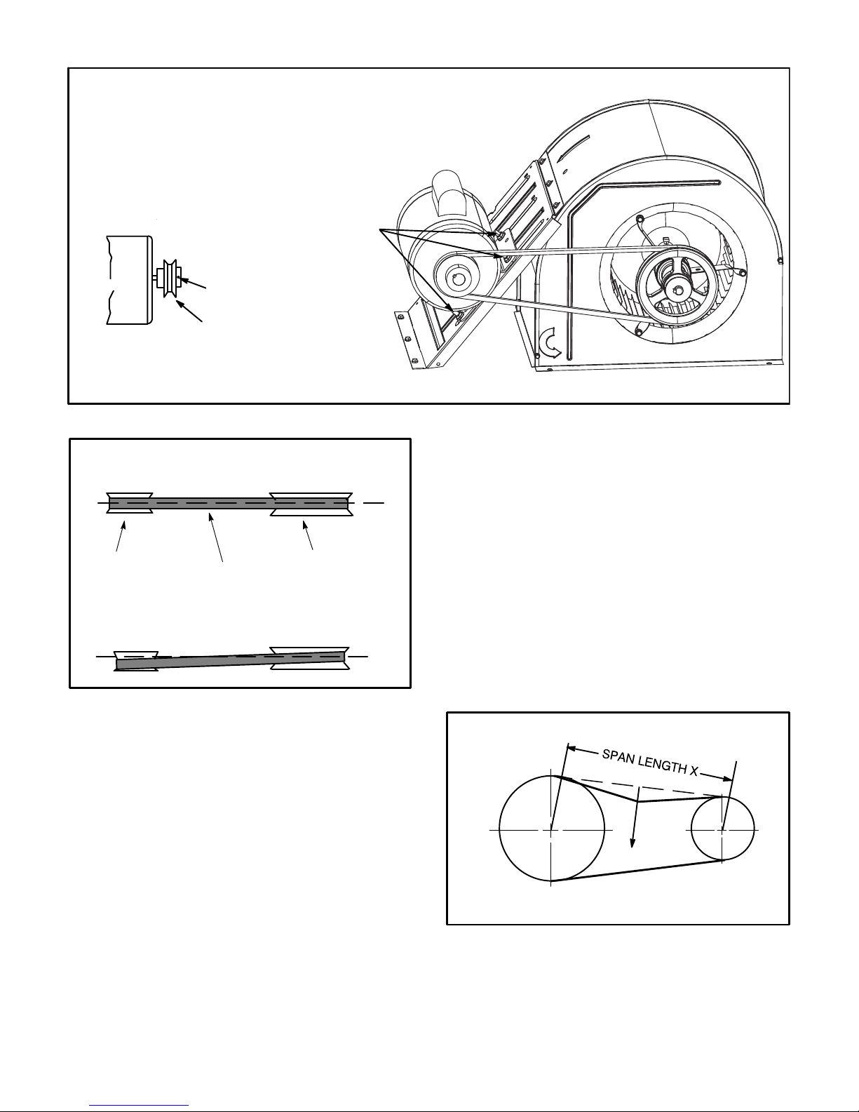
C - Blower Belt Adjustment
Maximum life and wear can be obtained from belts only if
proper pulley alignment and belt tension are maintained.
Tension new belts after a 24-48 hour period of operation.
This will allow belt to stretch and seat grooves. Make sure
blower and motor pulley are aligned as shown in figure 11.
INSTALLATIONS WITH DUCTWORK
ROOFTOP UNIT
READING LOCATION
SUPPLY
MAIN
RE
TURN
OFF OF MAIN RUN
DUCT RUN
LOCATION OF STATIC PRESSURE READINGS
INSTALLATIONS WITH CEILING DIFFUSERS
ROOFTOP UNIT
RETURN AIR
SUPPLY
FIRST BRANCH
SUPPLY AIR
READING
LOCATION
SUPPLY AIR
READING
LOCATION
DIFFUSER
FIGURE 9
Page 7
RETURN AIR
READING
RE
TURN
LOCATION
507111-02 2/2015
Page 8
BLOWER ASSEMBLY
TO INCREASE BELT TENSION
1-Loosen four bolts securing motor base to mounting frame.
2-Slide the motor downward to tighten the belt.
3-Tighten four bolts on motor base.
LOOSEN FOUR BOLTS
AND SLIDE BLOWER
MOTOR DOWNWARD
SIDE VIEW
TO TIGHTEN BELT
MOTOR
TO INCREASE CFM
LOOSEN ALLEN SCREW &
TURN PULLEY CLOCKWISE
ALLEN
SCREW
PULLEY
TO DECREASE CFM
TURN PULLEY
COUNTERCLOCKWISE
FIGURE 10
PULLEY ALIGNMENT
ALIGNED
MOTOR
PULLEY
BELT
NOT ALIGNED
BLOWER
PULLEY
FIGURE 11
1- Loosen four bolts securing motor base to mounting
frame. See figure 10.
2- Apply perpendicular force to center of span (X) with
enough pressure to deflect belt 1/64” for every inch
of span length or 1.5mm per 100mm of span length.
Example: Deflection distance of a 40” span would be
40/64” or 5/8”.
Example: Deflection distance of a 400mm span
would be 6mm.
3- Measure belt deflection force. For a used belt, the
deflection force should be 5 lbs. (35kPa). A new belt
deflection force should be 7 lbs. (48kPa).
A force below these values indicates an
undertensioned belt. A force above these values
indicates an overtensioned belt.
MEASURE BELT TENSION
2- To increase belt tension -
Slide blower motor downward to tighten the belt. This
increases the distance between the blower motor and
the blower housing.
To loosen belt tension -
Slide blower motor upward to loosen the belt. This
decreases the distance between the blower motor
and the blower housing.
3- Tighten four bolts securing motor base to the
mounting frame.
D - Check Belt Tension
Overtensioning belts shortens belt and bearing life.
Check belt tension as follows:
1- Measure span length X. See figure 12.
ZH 036, 048, 060
FORCE
DEFLECTION 1/64” PER INCH OF SPAN
OR 1.5mm PER 100mm OF SPAN
FIGURE 12
E-Field-Furnished Blower Drives
For field-furnished blower drives, use pages 9-14 to
determine BHP and RPM required. Reference page 15
for additional air resistance and drive kit numbers. See
table 2 for drive component manufacturer's numbers.
Page 8
Page 9

BLOWER DATA - BELT DRIVE - ZHA036
BLOWER TABLE INCLUDES RESISTANCE FOR BASE UNIT ONLY WITH DRY INDOOR COIL AND AIR FILTERS IN PLACE.
FOR ALL UNITS ADD:
1 - Any factory installed options air resistance (heat section, economizer, wet coil, etc.).
2 - Any eld installed accessories air resistance (duct resistance, diffuser, etc.).
See page 15 for blower motors and drives and wet coil and options/accessory air resistance data.
DOWNFLOW
Air
Volume
cfm
900 562 0.16 629 0.18 699 0.19 771 0.2 840 0.22 904 0.24 962 0.26 1015 0.29
1000 586 0.18 654 0.2 725 0.21 796 0.23 864 0.25 927 0.27 983 0.3 1034 0.33
1100 612 0.2 681 0.22 752 0.24 823 0.26 890 0.28 950 0.31 1004 0.34 1054 0.37
1200 641 0.23 711 0.25 783 0.27 852 0.29 917 0.32 975 0.35 1027 0.39 1074 0.42
1300 673 0.25 744 0.28 815 0.3 882 0.33 944 0.36 1000 0.4 1050 0.44 1096 0.48
1400 709 0.29 779 0.32 849 0.34 914 0.37 973 0.41 1026 0.45 1074 0.49 111 8 0.53
1500 747 0.33 816 0.36 883 0.39 945 0.42 1001 0.46 1052 0.51 1098 0.55 1141 0.59
Air
Volume
cfm
900 1065 0.32 1112 0.35 1158 0.38 1202 0.41 1243 0.44 1284 0.48 1323 0.52 1364 0.55
1000 1082 0.36 1128 0.39 1173 0.42 1216 0.45 1257 0.49 1297 0.53 1336 0.57 1375 0.6
1100 1100 0.4 1145 0.44 1189 0.47 1231 0.51 1272 0.54 1311 0.58 1349 0.62 1388 0.66
1200 111 9 0.45 1163 0.49 1206 0.52 1247 0.56 1287 0.6 1326 0.64 1364 0.68 1402 0.72
1300 1139 0.51 1182 0.55 1224 0.58 1265 0.62 1304 0.66 1342 0.71 1379 0.75 1416 0.79
1400 1160 0.57 1202 0.61 1243 0.65 1283 0.69 1322 0.73 1359 0.78 1396 0.82 1432 0.87
1500 1182 0.64 1223 0.68 1263 0.72 1303 0.76 1341 0.81 1378 0.85 1414 0.9 1449 0.94
HORIZONTAL
Air
Volume
cfm
900 580 0.14 649 0.17 721 0.19 794 0.22 868 0.24 938 0.27 998 0.3 1045 0.33
1000 612 0.17 681 0.19 752 0.22 825 0.25 897 0.27 963 0.3 1017 0.33 1061 0.37
1100 647 0.2 717 0.23 788 0.26 858 0.28 926 0.31 986 0.34 1036 0.38 1077 0.41
1200 687 0.23 757 0.26 826 0.29 893 0.32 955 0.35 1008 0.39 1054 0.42 1095 0.46
1300 730 0.27 798 0.3 864 0.33 926 0.37 982 0.4 1030 0.44 1073 0.47 1116 0.51
1400
1500 820 0.36 881 0.4 939 0.44 993 0.49 1039 0.53 1082 0.56 1124 0.59 1168 0.62
Air
Volume
cfm
900 1091 0.36 1140 0.38 1188 0.4 1232 0.43 1272 0.46 1309 0.49 1346 0.53 1383 0.57
1000 1105 0.4 1154 0.42 1201 0.45 1245 0.47 1284 0.5 1321 0.54 1357 0.58 1394 0.62
1100 1121 0.44 1169 0.47 1216 0.49 1259 0.52 1298 0.56 1335 0.6 1370 0.64 1406 0.69
1200 1139 0.49 1187 0.52 1234 0.54 1276 0.58 1314 0.62 1350 0.66 1385 0.71 1421 0.75
1300 1161 0.54 1208 0.57 1254 0.6 1295 0.64 1332 0.69 1366 0.73 1401 0.78 1436 0.83
1400 1185 0.59 1232 0.63 1276 0.67 1315 0.71 1351 0.76 1384 0.81 1419 0.86 1454 0.9
1500 1212 0.66 1257 0.7 1299 0.74 1337 0.79 1371 0.84 1404 0.89 1438 0.94 1473 0.99
0.10 0.20 0.30 0.40 0.50 0.60 0.70 0.80
RPM BHP RPM BHP RPM BHP RPM BHP RPM BHP RPM BHP RPM BHP RPM BHP
Field Furnished Kit ZA01
0.90 1.00 1.10 1.20 1.30 1.40 1.50 1.60
RPM BHP RPM BHP RPM BHP RPM BHP RPM BHP RPM BHP RPM BHP RPM BHP
0.10 0.20 0.30 0.40 0.50 0.60 0.70 0.80
RPM BHP RPM BHP RPM BHP RPM BHP RPM BHP RPM BHP RPM BHP RPM BHP
Field Furnished Kit ZA01 Kit ZA04
775 0.31 840 0.34 902 0.38 959 0.42 1009 0.46 1054 0.5 1096 0.53 1140 0.56
0.90 1.00 1.10 1.20 1.30 1.40 1.50 1.60
RPM BHP RPM BHP RPM BHP RPM BHP RPM BHP RPM BHP RPM BHP RPM BHP
External Static - in. w.g.
External Static - in. w.g.
Kit ZA04
External Static - in. w.g.
External Static - in. w.g.
Kit ZA04
Page 9
Page 10

BLOWER DATA - BELT DRIVE - ZHA048
BLOWER TABLE INCLUDES RESISTANCE FOR BASE UNIT ONLY WITH DRY INDOOR COIL AND AIR FILTERS IN PLACE.
FOR ALL UNITS ADD:
1 - Any factory installed options air resistance (heat section, economizer, wet coil, etc.).
2 - Any eld installed accessories air resistance (duct resistance, diffuser, etc.).
See page 15 for blower motors and drives and wet coil and options/accessory air resistance data.
DOWNFLOW
Air
Volume
cfm
1200 641 0.23 711 0.25 783 0.27 852 0.29 917 0.32 975 0.35 1027 0.39 1074 0.42
1300 673 0.25 744 0.28 815 0.30 882 0.33 944 0.36 1000 0.40 1050 0.44 1096 0.48
1400 709 0.29 779 0.32 849 0.34 914 0.37 973 0.41 1026 0.45 1074 0.49 111 8 0.53
1500 747 0.33 816 0.36 883 0.39 945 0.42 1001 0.46 1052 0.51 1098 0.55 1141 0.59
1600 787 0.38 854 0.41 918 0.44 976 0.48 1030 0.52 1078 0.56 1123 0.61 1164 0.66
1700 827 0.43 892 0.46 952 0.49 1007 0.53 1058 0.58 1105 0.63 1148 0.68 1189 0.73
1800 868 0.48 929 0.52 986 0.55 1038 0.59 1087 0.64 1132 0.69 1174 0.75 1214 0.80
1900 907 0.54 966 0.58 1019 0.62 1069 0.66 111 6 0.71 1160 0.77 1200 0.82 1240 0.88
2000 946 0.60 1001 0.65 1053 0.69 1101 0.74 1146 0.79 1188 0.85 1228 0.91 1267 0.98
Air
Volume
cfm
1200 111 9 0.45 1163 0.49 1206 0.52 1247 0.56 1287 0.60 1326 0.64 1364 0.68 1402 0.72
1300 1139 0.51 1182 0.55 1224 0.58 1265 0.62 1304 0.66 1342 0.71 1379 0.75 1416 0.79
1400 1160 0.57 1202 0.61 1243 0.65 1283 0.69 1322 0.73 1359 0.78 1396 0.82 1432 0.87
1500 1182 0.64 1223 0.68 1263 0.72 1303 0.76 1341 0.81 1378 0.85 1414 0.90 1449 0.94
1600 1205 0.70 1245 0.75 1284 0.79 1323 0.84 1361 0.88 1397 0.93 1432 0.98 1467 1.03
1700 1228 0.78 1268 0.82 1307 0.87 1345 0.92 1382 0.97 1417 1.02 1452 1.07 1486 1.11
1800 1253 0.85 1292 0.91 1331 0.96 1368 1.01 1404 1.06 1439 1.11 1473 1.16 1506 1.21
1900 1279 0.94 1317 1.00 1355 1.05 1392 1.10 1427 1.16 1461 1.21 1494 1.26 1527 1.31
2000 1305 1.04 1343 1.10 1380 1.15 1416 1.21 1450 1.26 1484 1.32 1516 1.37 1549 1.42
HORIZONTAL
Air
Volume
cfm
1200 687 0.23 757 0.26 826 0.29 893 0.32 955 0.35 1008 0.39 1054 0.42 1095 0.46
1300 730 0.27 798 0.30 864 0.33 926 0.37 982 0.40 1030 0.44 1073 0.47 111 6 0.51
1400
1500 820 0.36 881 0.40 939 0.44 993 0.49 1039 0.53 1082 0.56 1124 0.59 1168 0.62
1600 864 0.42 921 0.46 976 0.51 1027 0.56 1072 0.60 111 3 0.63 1155 0.66 1198 0.69
1700 907 0.48 961 0.53 1013 0.58 1061 0.63 1105 0.67 1146 0.70 1187 0.73 1230 0.77
1800 948 0.56 999 0.61 1049 0.66 1096 0.71 1139 0.75 1180 0.78 1221 0.82 1262 0.86
1900 987 0.64 1037 0.69 1086 0.74 1132 0.79 1174 0.83 1214 0.86 1255 0.90 1295 0.95
2000 1028 0.73 1076 0.78 1123 0.83 1168 0.87 1210 0.91 1250 0.96 1289 1.00 1328 1.06
Air
Volume
cfm
1200 1139 0.49 1187 0.52 1234 0.54 1276 0.58 1314 0.62 1350 0.66 1385 0.71 1421 0.75
1300 1161 0.54 1208 0.57 1254 0.60 1295 0.64 1332 0.69 1366 0.73 1401 0.78 1436 0.83
1400 1185 0.59 1232 0.63 1276 0.67 1315 0.71 1351 0.76 1384 0.81 1419 0.86 1454 0.90
1500 1212 0.66 1257 0.70 1299 0.74 1337 0.79 1371 0.84 1404 0.89 1438 0.94 1473 0.99
1600 1242 0.73 1284 0.77 1324 0.82 1360 0.88 1394 0.93 1426 0.99 1460 1.04 1495 1.08
1700 1272 0.81 1312 0.86 1350 0.92 1385 0.98 1418 1.04 1451 1.09 1485 1.14 1519 1.19
1800 1302 0.90 1341 0.96 1377 1.02 1411 1.08 1444 1.15 1477 1.20 1510 1.25 1544 1.30
1900 1334 1.01 1371 1.07 1406 1.13 1439 1.20 1471 1.26 1504 1.32 1537 1.37 1571 1.41
2000 1365 1.12 1401 1.19 1435 1.25 1468 1.32 1500 1.38 1532 1.44 1565 1.49 1598 1.53
0.10 0.20 0.30 0.40 0.50 0.60 0.70 0.80
RPM BHP RPM BHP RPM BHP RPM BHP RPM BHP RPM BHP RPM BHP RPM BHP
Field Furnished Kit ZA02
0.90 1.00 1.10 1.20 1.30 1.40 1.50 1.60
RPM BHP RPM BHP RPM BHP RPM BHP RPM BHP RPM BHP RPM BHP RPM BHP
Kit ZA02 Kit ZA05
0.10 0.20 0.30 0.40 0.50 0.60 0.70 0.80
RPM BHP RPM BHP RPM BHP RPM BHP
Field Furnished Kit ZA02
775 0.31 840 0.34 902 0.38 959 0.42 1009 0.46 1054 0.50 1096 0.53 1140 0.56
0.90 1.00 1.10 1.20 1.30 1.40 1.50 1.60
RPM BHP RPM BHP RPM BHP RPM BHP RPM BHP RPM BHP RPM BHP RPM BHP
Kit ZA02 Kit ZA05
External Static - in. w.g.
External Static - in. w.g.
External Static - in. w.g.
RPM BHP RPM BHP RPM BHP RPM BHP
External Static - in. w.g.
Page 10
Page 11

BLOWER DATA - BELT DRIVE - ZHA060
BLOWER TABLE INCLUDES RESISTANCE FOR BASE UNIT ONLY WITH DRY INDOOR COIL AND AIR FILTERS IN PLACE.
FOR ALL UNITS ADD:
1 - Any factory installed options air resistance (heat section, economizer, wet coil, etc.).
2 - Any eld installed accessories air resistance (duct resistance, diffuser, etc.).
See page 15 for blower motors and drives and wet coil and options/accessory air resistance data.
DOWNFLOW
Air
Volume
cfm
1600 764 0.35 822 0.39 880 0.42 936 0.46 991 0.51 1042 0.55 1091 0.60 1136 0.64
1700 801 0.40 857 0.44 913 0.48 968 0.52 1020 0.57 1070 0.61 111 7 0.66 1162 0.71
1800 838 0.46 893 0.50 947 0.54 1000 0.58 1051 0.63 1099 0.68 1145 0.73 1188 0.78
1900 876 0.52 929 0.56 982 0.61 1033 0.65 1082 0.70 1129 0.75 1173 0.80 1215 0.85
2000 914 0.59 966 0.63 1017 0.68 1067 0.72 111 5 0.77 1160 0.83 1203 0.88 1244 0.94
2100 953 0.66 1004 0.71 1054 0.76 1102 0.81 1148 0.86 1192 0.92 1233 0.98 1273 1.04
2200 993 0.74 1042 0.79 1090 0.85 1137 0.90 1181 0.96 1224 1.02 1264 1.09 1303 1.15
2300 1033 0.83 1081 0.89 1128 0.94 1173 1.01 1216 1.07 1257 1.14 1296 1.20 1334 1.27
2400 1074 0.93 1120 0.99 1166 1.05 1209 1.12 1251 1.19 1291 1.26 1329 1.33 1366 1.41
Air
Volume
cfm
1600 1180 0.68 1222 0.72 1263 0.76 1303 0.80 1341 0.85 1378 0.90 1414 0.94 1449 0.99
1700 1204 0.75 1245 0.79 1285 0.84 1325 0.88 1362 0.93 1398 0.98 1434 1.03 1468 1.08
1800 1229 0.83 1270 0.87 1309 0.92 1347 0.97 1384 1.02 1420 1.07 1454 1.12 1488 1.17
1900 1256 0.91 1296 0.96 1334 1.01 1371 1.07 1407 1.12 1442 1.17 1476 1.23 1509 1.28
2000 1284 1.00 1322 1.06 1360 1.11 1396 1.17 1431 1.23 1465 1.28 1498 1.33 1531 1.38
2100 1312 1.10 1350 1.16 1386 1.22 1422 1.28 1456 1.34 1489 1.40 1521 1.45 1554 1.50
2200 1341 1.22 1378 1.28 1414 1.34 1448 1.41 1481 1.46 1513 1.52 1546 1.57 1578 1.62
2300 1371 1.34 1407 1.41 1442 1.47 1475 1.54 1507 1.59 1539 1.65 1571 1.70 1602 1.75
2400 1402 1.48 1436 1.55 1470 1.61 1503 1.67 1535 1.73 1566 1.79 1597 1.84 1628 1.89
HORIZONTAL
Air
Volume
cfm
1600 783 0.38 844 0.41 902 0.44 957 0.48 1008 0.52 1056 0.56 1100
1700 825 0.44 882 0.47 938 0.50 989 0.54 1038 0.57 1083 0.62 1126 0.66 1166 0.71
1800 866 0.50 921 0.53 973 0.56 1021 0.60 1067 0.64 1111 0.68 1152 0.73 1191 0.78
1900 907 0.56 959 0.59 1008 0.63 1054 0.66 1098 0.71 1139 0.75 1179 0.80 1217 0.86
2000 948 0.63 996 0.66 1042 0.70 1086 0.74 1128 0.78 1168 0.83 1207 0.89 1244 0.94
2100 987 0.70 1033 0.74 1077 0.78 111 9 0.82 1159 0.87 1198 0.93 1235 0.99 1272 1.05
2200 1026 0.78 1070 0.82 111 2 0.87 1152 0.92 1191 0.98 1228 1.03 1265 1.10 1301 1.16
2300 1064 0.88 1106 0.92 1147 0.97 1186 1.03 1223 1.09 1260 1.15 1295 1.22 1331 1.28
2400 1102 0.98 1143 1.03 1182 1.08 1220 1.15 1256 1.21 1292 1.28 1327 1.35 1362 1.42
Air
Volume
cfm
1600 1183 0.68 1223 0.72 1263 0.76 1302 0.81 1340 0.86 1377 0.91 1413 0.95 1448 1.00
1700 1205 0.75 1245 0.79 1284 0.84 1322 0.89 1360 0.94 1396 0.99 1431 1.04 1465 1.09
1800 1230 0.83 1268 0.87 1306 0.92 1344 0.98 1380 1.03 1416 1.08 1450 1.13 1483 1.19
1900 1255 0.91 1292 0.96 1330 1.02 1367 1.07 1402 1.13 1437 1.18 1470 1.24 1503 1.29
2000 1281 1.00 1318 1.06 1355 1.12 1391 1.18 1425 1.23 1459 1.29 1492 1.35 1524 1.40
2100 1308 1.11 1345 1.17 1381 1.23 1416 1.29 1450 1.35 1482 1.41 1514 1.46 1546 1.52
2200 1337 1.23 1372 1.29 1408 1.35 1442 1.42 1475 1.47 1507 1.53 1538 1.59 1569 1.64
2300 1366 1.35 1401 1.42 1435 1.49 1469 1.55 1501 1.61 1532 1.67 1563 1.72 1594 1.77
2400 1396 1.49 1431 1.56 1464 1.63 1496 1.69 1528 1.75 1559 1.81 1589 1.86 1619 1.91
0.10 0.20 0.30 0.40 0.50 0.60 0.70 0.80
RPM BHP RPM BHP RPM BHP RPM BHP RPM BHP RPM BHP RPM BHP RPM BHP
Field Furnished Kit ZA03
0.90 1.00 1.10 1.20 1.30 1.40 1.50 1.60
RPM BHP RPM BHP RPM BHP RPM BHP RPM BHP RPM BHP RPM BHP RPM BHP
0.10 0.20 0.30 0.40 0.50 0.60 0.70 0.80
RPM BHP RPM BHP RPM BHP RPM BHP
Field Furnished Kit ZA03
0.90 1.00 1.10 1.20 1.30 1.40 1.50 1.60
RPM BHP RPM BHP RPM BHP RPM BHP RPM BHP RPM BHP RPM BHP RPM BHP
External Static - in. w.g.
External Static - in. w.g.
Kit ZA03 Kit ZA06
External Static - in. w.g.
RPM BHP RPM BHP RPM BHP RPM BHP
0.60 1142 0.64
External Static - in. w.g.
Kit ZA03 Kit ZA06
Page 11
Page 12

BLOWER DATA - BELT DRIVE - ZHB036
BLOWER TABLE INCLUDES RESISTANCE FOR BASE UNIT ONLY WITH DRY INDOOR COIL AND AIR FILTERS IN PLACE.
FOR ALL UNITS ADD:
1 - Any factory installed options air resistance (heat section, economizer, wet coil, etc.).
2 - Any eld installed accessories air resistance (duct resistance, diffuser, etc.).
See page 15 for blower motors and drives and wet coil and options/accessory air resistance data.
DOWNFLOW
Air
Volume
cfm
900 562 0.11 621 0.13 685 0.16 752 0.18 818 0.21 883 0.24 944 0.27 1001 0.30
1000 584 0.13 644 0.16 707 0.18 773 0.21 838 0.24 901 0.27 960 0.3 1015 0.33
1100 609 0.16 669 0.18 732 0.21 796 0.24 860 0.27 921 0.30 978 0.34 1031 0.37
1200 635 0.19 696 0.21 758 0.24 821 0.27 883 0.31 942 0.34 997 0.38 1049 0.42
1300 664 0.22 725 0.25 786 0.28 848 0.31 908 0.35 965 0.39 1018 0.43 1068 0.47
1400 696 0.26 756 0.29 816 0.32 876 0.36 935 0.40 989 0.44 1041 0.48 1089 0.52
1500 729 0.30 788 0.33 848 0.37 906 0.41 962 0.45 1015 0.50 1065 0.54 111 2 0.58
Air
Volume
cfm
900 1053 0.32 1103 0.35 1149 0.38 1193 0.41 1234 0.43 1274 0.47 1312 0.50 1351 0.53
1000 1066 0.36 1114 0.39 1160 0.42 1204 0.45 1245 0.48 1284 0.51 1322 0.54 1361 0.58
1100 1081 0.40 1128 0.43 1173 0.46 1216 0.49 1257 0.53 1296 0.56 1334 0.60 1372 0.63
1200 1097 0.45 1144 0.48 1188 0.51 1231 0.54 1271 0.58 1310 0.62 1347 0.66 1385 0.69
1300 111 5 0.50 1161 0.53 1204 0.56 1246 0.60 1286 0.64 1325 0.68 1362 0.72 1399 0.76
1400 1135 0.56 1179 0.59 1222 0.62 1264 0.66 1303 0.70 1341 0.75 1378 0.79 1415 0.83
1500 1157 0.62 1200 0.65 1242 0.69 1282 0.73 1321 0.77 1359 0.82 1396 0.86 1431 0.91
HORIZONTAL
Air
Volume
cfm
900 560 0.16 624 0.18 692 0.20 761 0.21 830 0.23 896 0.25 956 0.27 1012 0.29
1000 583 0.18 647 0.20 715 0.22 783 0.24 850 0.25 914 0.27 972 0.30 1025 0.33
1100 609 0.20 673 0.22 740 0.24 808 0.26 873 0.28 934 0.31 990 0.34 1041 0.37
1200 637 0.23 702 0.25 769 0.27 835 0.29 898 0.32 956 0.35 1009 0.38 1058 0.41
1300 669 0.26 734 0.28 800 0.30 863 0.33 924 0.36 979 0.39 1030 0.43 1077 0.46
1400 704 0.29 768 0.32 832 0.35 894 0.37 951 0.41 1004 0.44 1052 0.48 1097 0.52
1500 742 0.33 805 0.36 867 0.39 925 0.42 980 0.46 1030 0.50 1076 0.54 111 9 0.58
Air
olume
V
cfm
900 1064 0.32 111 4 0.35 1162 0.38 1208 0.41 1251 0.45 1293 0.49 1333 0.52 1373 0.56
1000 1076 0.36 1124 0.39 1170 0.42 1216 0.46 1259 0.49 1300 0.53 1340 0.57 1379 0.61
1100 1089 0.40 1136 0.43 1181 0.46 1225 0.50 1268 0.54 1308 0.58 1347 0.62 1386 0.66
1200 1104 0.45 1150 0.48 1194 0.51 1237 0.55 1279 0.59 1319 0.63 1357 0.67 1394 0.71
1300 1121 0.5 1165 0.53 1209 0.57 1251 0.61 1292 0.65 1331 0.69 1368 0.73 1405 0.78
1400 1140 0.56 1183 0.59 1225 0.63 1266 0.67 1306 0.71 1345 0.76 1382 0.8 1417 0.85
1500 1161 0.62 1202 0.65 1243 0.69 1284 0.73 1323 0.78 1360 0.83 1396 0.87 1432 0.92
0.10 0.20 0.30 0.40 0.50 0.60 0.70 0.80
RPM BHP RPM BHP RPM BHP RPM BHP RPM BHP RPM BHP RPM BHP RPM BHP
Field Furnished Kit ZA01
0.90 1.00 1.10 1.20 1.30 1.40 1.50 1.60
RPM BHP RPM BHP RPM BHP RPM BHP RPM BHP RPM BHP RPM BHP RPM BHP
0.10 0.20 0.30 0.40 0.50 0.60 0.70 0.80
RPM BHP RPM BHP RPM BHP RPM BHP RPM BHP RPM BHP RPM BHP RPM BHP
Field Furnished Kit ZA01
0.90 1.00 1.10 1.20 1.30 1.40 1.50 1.60
RPM BHP RPM BHP RPM BHP RPM BHP RPM BHP RPM BHP RPM BHP RPM BHP
External Static - in. w.g.
External Static - in. w.g.
Kit ZA04
External Static - in. w.g.
External Static - in. w.g.
Kit ZA04
Page 12
Page 13

BLOWER DATA - BELT DRIVE - ZHB048
BLOWER TABLE INCLUDES RESISTANCE FOR BASE UNIT ONLY WITH DRY INDOOR COIL AND AIR FILTERS IN PLACE.
FOR ALL UNITS ADD:
1 - Any factory installed options air resistance (heat section, economizer, wet coil, etc.).
2 - Any eld installed accessories air resistance (duct resistance, diffuser, etc.).
See page 15 for blower motors and drives and wet coil and options/accessory air resistance data.
DOWNFLOW
Air
Volume
cfm
1200 620 0.23 681 0.29 744 0.34 809 0.39 875 0.43 941 0.47 1004 0.51 1060 0.54
1300 652 0.28 713 0.34 775 0.39 839 0.44 903 0.48 967 0.51 1025 0.55 1078 0.59
1400 687 0.33 747 0.39 809 0.44 871 0.49 934 0.53 994 0.57 1048 0.61 1098 0.64
1500 724 0.40 784 0.45 844 0.50 905 0.54 965 0.59 1021 0.62 1071 0.66 111 8 0.70
1600 764 0.46 823 0.51 882 0.56 940 0.60 997 0.65 1048 0.69 1094 0.72 1140 0.75
1700 806 0.53 863 0.58 919 0.62 975 0.67 1028 0.71 1075 0.75 111 9 0.78 1164 0.81
1800 849 0.60 903 0.65 957 0.69 1010 0.74 1058 0.78 1102 0.82 1145 0.85 1189 0.88
1900 892 0.68 944 0.72 995 0.77 1045 0.82 1089 0.86 1131 0.89 1174 0.92 1217 0.95
2000 935 0.76 984 0.81 1033 0.86 1079 0.91 1122 0.95 1163 0.97 1204 1.00 1247 1.03
Air
Volume
cfm
1200 1111 0.58 1156 0.60 1199 0.62 1241 0.63 1284 0.65 1326 0.67 1367 0.71 1408 0.74
1300 1127 0.62 1172 0.65 1214 0.66 1256 0.68 1299 0.70 1341 0.73 1381 0.77 1421 0.81
1400 1145 0.68 1189 0.70 1231 0.72 1274 0.74 1316 0.76 1357 0.79 1397 0.83 1436 0.88
1500 1164 0.73 1208 0.75 1251 0.78 1293 0.80 1334 0.83 1374 0.86 1413 0.91 1451 0.95
1600 1185 0.79 1229 0.81 1271 0.84 1313 0.86 1354 0.90 1393 0.94 1431 0.98 1468 1.03
1700 1208 0.84 1252 0.87 1294 0.90 1335 0.94 1375 0.98 1413 1.02 1449 1.07 1485 1.12
1800 1233 0.91 1276 0.94 1318 0.98 1358 1.02 1397 1.06 1434 1.11 1469 1.16 1504 1.21
1900 1261 0.98 1303 1.02 1343 1.06 1382 1.11 1420 1.16 1455 1.21 1490 1.26 1525 1.31
2000 1289 1.07 1330 1.11 1370 1.16 1407 1.21 1444 1.27 1478 1.32 1513 1.37 1547 1.42
HORIZONTAL
Air
Volume
cfm
1200 614 0.21 681 0.25 752 0.30 821 0.34 888 0.39 950 0.43 1006 0.46 1057 0.49
1300 644 0.24 712 0.29 782 0.34 850 0.39 915 0.43 974 0.47 1027 0.51 1076 0.53
1400 677 0.29 746 0.34 814 0.39 880 0.44 942 0.48 998 0.52 1049 0.55 1097 0.58
1500 714 0.34 781 0.40 848 0.45 911 0.49
1600 752 0.40 818 0.45 882 0.50 943 0.55 999 0.59 1050 0.62 1097 0.66 1142 0.69
1700 792 0.46 855 0.52 917 0.56 975 0.61 1028 0.64 1077 0.68 1123 0.72 1166 0.75
1800 832 0.53 894 0.58 952 0.63 1007 0.67 1058 0.70 1105 0.74 1149 0.78 1192 0.82
1900 873 0.60 932 0.65 988 0.69 1040 0.73 1088 0.77 1134 0.81 1177 0.85 1219 0.90
2000 914 0.67 970 0.72 1023 0.76 1073 0.80 1120 0.85 1163 0.89 1205 0.94 1246 0.99
Air
Volume
cfm
1200 1105 0.51 1152 0.53 1197 0.55 1240 0.58 1280 0.61 1320 0.64 1358 0.68 1395 0.72
1300 1123 0.55 1169 0.57 1213 0.60 1255 0.63 1295 0.67 1334 0.70 1372 0.74 1409 0.79
1400 1142 0.60 1187 0.63 1230 0.66 1272 0.69 1312 0.73 1350 0.77 1388 0.82 1424 0.86
1500 1163 0.66 1207 0.69 1249 0.72 1290 0.76 1330 0.80 1368 0.85 1405 0.90 1441 0.94
1600 1185 0.72 1228 0.75 1270 0.79 1310 0.83 1349 0.88 1387 0.93 1423 0.98 1459 1.03
1700 1209 0.78 1251 0.82 1292 0.87 1331 0.92 1370 0.97 1407 1.02 1443 1.07 1478 1.12
1800 1234 0.86 1275 0.91 1315 0.96 1354 1.01 1391 1.06 1428 1.11 1463 1.17 1498 1.22
1900 1260 0.95 1300 1.00 1340 1.05 1377 1.11 1414 1.16 1450 1.22 1485 1.27 1519 1.32
2000 1287 1.04 1326 1.10 1365 1.16 1402 1.21 1437 1.27 1472 1.33 1507 1.38 1541 1.43
0.10 0.20 0.30 0.40 0.50 0.60 0.70 0.80
RPM BHP RPM BHP RPM BHP RPM BHP RPM BHP RPM BHP RPM BHP RPM BHP
Field Furnished Kit ZA02
0.90 1.00 1.10 1.20 1.30 1.40 1.50 1.60
RPM BHP RPM BHP RPM BHP RPM BHP RPM BHP RPM BHP RPM BHP RPM BHP
Kit ZA02 Kit ZA05
0.10 0.20 0.30 0.40 0.50 0.60 0.70 0.80
RPM BHP RPM BHP RPM BHP RPM BHP
Field Furnished Kit ZA02
0.90 1.00 1.10 1.20 1.30 1.40 1.50 1.60
RPM BHP RPM BHP RPM BHP RPM BHP RPM BHP RPM BHP RPM BHP RPM BHP
Kit ZA02 Kit ZA05
External Static - in. w.g.
External Static - in. w.g.
External Static - in. w.g.
RPM BHP RPM BHP RPM BHP RPM BHP
970 0.53 1023 0.57 1072 0.60 111 9 0.63
External Static - in. w.g.
Page 13
Page 14

BLOWER DATA - BELT DRIVE - ZHB060
BLOWER TABLE INCLUDES RESISTANCE FOR BASE UNIT ONLY WITH DRY INDOOR COIL AND AIR FILTERS IN PLACE.
FOR ALL UNITS ADD:
1 - Any factory installed options air resistance (heat section, economizer, wet coil, etc.).
2 - Any eld installed accessories air resistance (duct resistance, diffuser, etc.).
See page 15 for blower motors and drives and wet coil and options/accessory air resistance data.
DOWNFLOW
Air
Volume
cfm
1600 522 0.27 552 0.32 585 0.37 619 0.43 656 0.48 693 0.53 732 0.59 771 0.64
1700 539 0.32 570 0.37 603 0.43 638 0.48 674 0.53 711 0.59 749 0.64 787 0.69
1800 558 0.38 589 0.43 623 0.48 658 0.54 694 0.59 730 0.64 767 0.70 803 0.75
1900 578 0.44 610 0.49 643 0.54 678 0.60 714 0.65 749 0.70 785 0.76 819 0.82
2000 600 0.50 632 0.56 665 0.61 699 0.66 734 0.71 769 0.77 803 0.83 837 0.90
2100 623 0.57 655 0.62 688 0.68 721 0.73 755 0.79 789 0.84 822 0.91 854 0.98
2200 647 0.65 678 0.70 711 0.75 743 0.81 776 0.86 809 0.93 841 1.00 872 1.06
2300 671 0.73 702 0.78 734 0.83 766 0.89 798 0.95 829 1.02 860 1.09 890 1.16
2400 696 0.81 726 0.87 757 0.92 788 0.98 819 1.04 850 1.11 880 1.19 909 1.26
Air
Volume
cfm
1600 809 0.69 844 0.74 877 0.80 908 0.85 936 0.91 963 0.97 989 1.02 1014 1.08
1700 823 0.75 857 0.80 889 0.86 919 0.92 947 0.97 973 1.03 999 1.09 1024 1.14
1800 838 0.81 870 0.87 901 0.92 931 0.98 958 1.04 984 1.10 1009 1.16 1034 1.22
1900 853 0.88 885 0.94 915 0.99 944 1.05 971 1.11 996 1.17 1021 1.23 1045 1.29
2000 869 0.96 899 1.01 929 1.07 957 1.13 984 1.19 1009 1.25 1033 1.31 1058 1.38
2100 885 1.04 915 1.10 944 1.15 971 1.22 997 1.28 1022 1.34 1046 1.40 1070 1.46
2200 902 1.13 931 1.19 959 1.24 986 1.31 1012 1.37 1036 1.43 1060 1.50 1084 1.56
2300 920 1.23 948 1.29 975 1.35 1001 1.41 1027 1.47 1051 1.53 1075 1.60 1098 1.66
2400 938 1.33 965 1.39 992 1.45 1017 1.52 1042 1.58 1066 1.64 1090 1.70 111 3 1.77
HORIZONTAL
Air
Volume
cfm
1600 525 0.30 561 0.34 597 0.39 635 0.43 673 0.47 711 0.51 748
1700 543 0.34 578 0.39 615 0.43 653 0.48 691 0.52 728 0.57 765 0.62 800 0.67
1800 561 0.39 597 0.44 635 0.49 672 0.53 710 0.58 746 0.63 782 0.68 816 0.73
1900 581 0.44 618 0.49 655 0.54 692 0.59 729 0.64 765 0.69 800 0.75 833 0.80
2000 602 0.50 639 0.55 676 0.61 713 0.66 749 0.71 784 0.76 818 0.82 850 0.88
2100 625 0.57 661 0.62 698 0.67 735 0.73 770 0.78 804 0.84 837 0.90 868 0.96
2200 648 0.64 685 0.69 721 0.75 757 0.80 791 0.86 824 0.92 856 0.98 886 1.05
2300 673 0.71 709 0.77 745 0.83 780 0.88 813 0.94 845 1.01 876 1.08 905 1.15
2400 699 0.79 734 0.85 769 0.91 803 0.97 835 1.04 866 1.11 896 1.18 924 1.25
Air
Volume
cfm
1600 819 0.66 851 0.72 883 0.77 913 0.83 943 0.89 971 0.95 998 1.01 1024 1.07
1700 833 0.72 865 0.78 896 0.84 926 0.90 954 0.96 982 1.02 1009 1.08 1034 1.14
1800 848 0.79 880 0.85 910 0.92 939 0.98 967 1.04 994 1.10 1020 1.16 1045 1.23
1900 864 0.87 895 0.93 924 0.99 953 1.06 980 1.12 1007 1.18 1032 1.25 1056 1.31
2000 881 0.95 911 1.01 940 1.08 967 1.14 994 1.21 1020 1.27 1044 1.34 1068 1.40
2100 898 1.03 927 1.10 955 1.17 982 1.23 1008 1.30 1033 1.37 1057 1.43 1080 1.50
2200 916 1.12 944 1.19 971 1.26 998 1.33 1023 1.40 1047 1.47 1071 1.54 1093 1.60
2300 934 1.22 961 1.29 988 1.36 1014 1.43 1038 1.50 1062 1.58 1085 1.65 1107 1.71
2400 952 1.32 979 1.40 1005 1.47 1030 1.54 1054 1.62 1077 1.69 1099 1.76 1121 1.83
0.10 0.20 0.30 0.40 0.50 0.60 0.70 0.80
RPM BHP RPM BHP RPM BHP RPM BHP RPM BHP RPM BHP RPM BHP RPM BHP
Kit ZAA01 Kit ZAA02
0.90 1.00 1.10 1.20 1.30 1.40 1.50 1.60
RPM BHP RPM BHP RPM BHP RPM BHP RPM BHP RPM BHP RPM BHP RPM BHP
Kit ZAA02 Kit ZAA03
0.10 0.20 0.30 0.40 0.50 0.60 0.70 0.80
RPM BHP RPM BHP RPM BHP RPM BHP
Kit ZAA01 Kit ZAA02
0.90 1.00 1.10 1.20 1.30 1.40 1.50 1.60
RPM BHP RPM BHP RPM BHP RPM BHP RPM BHP RPM BHP RPM BHP RPM BHP
Kit ZAA02 Kit ZAA03
External Static - in. w.g.
External Static - in. w.g.
External Static - in. w.g.
RPM BHP RPM BHP RPM BHP RPM BHP
0.56 784 0.61
External Static - in. w.g.
Page 14
Page 15

BLOWER DATA
DRIVE KIT SPECIFICATIONS
Model No.
ZHA/ZHB036
ZHA/ZHB048
ZHA060
ZHB060
NOTE - Using total air volume and system static pressure requirements determine from blower performance tables rpm and motor hp required. Maximum usable hp of
motors furnished are shown. In Canada, nominal motor hp is also maximum usable motor hp. If motors of comparable hp are used, be sure to keep within the service
factor limitations outlined on the motor nameplate.
1
1 hp blower motor is not available for 208/230V-1ph applications. 2 1.5 hp motor is required with ZA05, ZA06 and ZAA03 drive kits.
POWER EXHAUST FAN PERFORMANCE
Return Air System Static Pressure - in. w.g.
OPTIONS / ACCESSORIES AIR RESISTANCE - in. w.g.
Air Volume
cfm
900 0.01 0.01 - - - 0.05 0.03 0.04
1000 0.02 0.01 - - - 0.06 0.03 0.05
1100 0.02 0.02 - - - 0.08 0.04 0.05
1200 0.02 0.02 0.01 0.09 0.05 0.06
1300 0.03 0.02 0.02 0.12 0.05 0.07
1400 0.03 0.03 0.02 0.17 0.06 0.08
1500 0.04 0.03 0.02 0.22 0.07 0.08
1600 0.04 0.03 0.03 0.26 0.08 0.09
1700 0.05 0.04 0.03 0.30 0.09 0.10
1800 0.05 0.04 0.03 0.33 0.10 0.11
1900 0.06 0.05 0.04 0.33 0.11 0.12
2000 0.06 0.05 0.04 0.31 0.12 0.13
2100 - - - 0.06 0.05 0.27 0.13 0.14
2200 - - - 0.06 0.05 0.29 0.14 0.15
2300 - - - 0.07 0.05 0.31 0.15 0.16
2400 - - - 0.07 0.06 0.32 0.16 0.18
CEILING DIFFUSERS AIR RESISTANCE (in. w.g.)
Air Volume
cfm
800 0.15 0.13 0.11 0.11
1000 0.19 0.16 0.14 0.14
1200 0.25 0.20 0.17 0.17
1400 0.33 0.26 0.20 0.20
1600 0.43 0.32 0.20 0.24
1800 0.56 0.40 0.30 0.30
2000 0.73 0.50 0.36 0.36
2200 0.95 0.63 0.44 0.44
Nominal Maximum Nominal Maximum
1
1
1
1
1
1
1
1
0.00 1865
0.05 1785
0.10 1710
0.15 1630
0.20 1545
0.25 1450
0.30 1350
0.35 1240
ZHA036, ZHA048 ZHA060, ZHB036 ZHB048, ZHB060 Downow Horizontal
RTD9-65 Step-Down Diffuser
2 Ends
Open
1 Side &
2 Ends Open
Blower Motor Choice (HP)
1
1.15 1.5 1.7
1
1.15 1.5 1.7
1
1.15 1.5 1.7
1
1.15 1.5 1.7
Wet Indoor Coil
CEILING DIFFUSER AIR THROW DATA
FD9-65
All Ends &
Sides Open
Flush
Diffuser
Page 15
Drive Kit No. RPM Range
ZA01 678 - 1035
ZA04 964 - 1471
ZA02 803 - 1226
2
ZA05 1098 - 1490
ZA03 906-1383
2
ZA06 1262-1634
ZAA01 522 - 784
ZAA02 632 - 875
2
ZAA03 798 - 1105
Air Volume Exhausted
cfm
Electric
Economizer
Heat
1
Air Volume - cfm
Effective Throw - ft.
Model No. RTD9-65 FD9-65
800 10 - 17 14 - 18
1000 10 - 17 15 - 20
1200 11 - 18 16 - 22
1400 12 - 19 17 - 24
1600 12 - 20 18 - 25
1800 13 - 21 20 - 28
2000 14 - 23 21 - 29
2200 16 - 25 22 - 30
1
Effective throw based on terminal velocities of 75 ft. per minute.
Page 16

TABLE 2
DRIVE COMPONENT MANUFACTURER'S NUMBERS
DRIVE COMPONENT PART NUMBERS
Drive No.
Z01 1VP34 X 7/8 31K6901 AK54 X 5/8 10024430 A40 10024517
Z02 1VP34 X 7/8 31K6901 AK46 X 5/8 10024431 A39 10024516
Z03 1VP34 X 7/8 31K6901 AK41 X 5/8 10024428 A39 10024516
Z04 1VP34 X 7/8 31K6901 AK39 X 5/8 10024432 A38 10024515
Z05 1VP44 X 7/8 P81488 AK49 X 5/8 10024426 A41 10024518
Z06 1VP50 X 7/8 53J1501 AK51 X 5/8 10024429 A42 10024519
ZAA01 1VP34 X 7/8 31K69 AK69 X 1 37L47 AX51 13H01
ZAA02 1VP40 X 7/8 79J03 BK80H 100788-03 A53 100245-40
ZAA03 1VP40 X 7/8 79J03 AK59 X 1 31K68 A50 100245-29
MINIMUM AIRFLOW - UNITS WITH ELECTRIC HEAT
kW
CFM - Downflow and Horizontal
ZHA036-060, ZHB036-048 ZHB060
5 960 1750
7.5 960 1750
10 960 1750
Motor Pulley Blower Pulley Belts
Browning OEM Browning OEM Browning OEM
TABLE 3
A first-stage Y1 cooling demand will energize L1
reversing valve solenoid and compressor 1.
Units With Optional Economizer The optional economizer will start on a first stage (Y1)
cooling demand when outdoor air is suitable. An
increased cooling demand (Y2) will energize
compressor 1.
15 960 1750
22.5 1280 1750
Units with electric heat (5-22.5kW) can operate up to 1.6”w.g. maximum static pressure.
2- Refrigerant circuits are factory charged with R-410A
refrigerant. See unit rating plate for correct amount of
charge.
Start-Up
B-Three Phase Scroll Compressor Voltage Phasing
IMPORTANT
This unit is equipped with a crankcase heater. Make
sure heater is energized 24 hours before unit startup to prevent compressor damage as a result of
slugging.
A-Start-Up
Heating
1- Set thermostat or temperature control device to
initiate a first-stage heating demand.
2- A first-stage heating demand (W1) will energize
compressors 1 and the outdoor fan.
Note - L1 reversing valve is de-energized in the
heating mode.
ZH Units With Optional Electric Heat -
An increased heating demand (W2) will energize
electric heat. Electric heat is also energized during
the defrost cycle (W1) to maintain discharge air
temperature.
Cooling
1- Set thermostat or temperature control device fan
switch to AUTO or ON. Set thermostat or
temperature control device to initiate a first-stage
cooling demand.
ZH 036, 048, 060
Three phase scroll compressors must be phased
sequentially to ensure correct compressor and blower
rotation and operation. Compressor and blower are
wired in phase at the factory. Power wires are
color-coded as follows: line 1-red, line 2-yellow, line
3-blue.
1- Observe suction and discharge pressures and
blower rotation on unit start-up.
2- Suction pressure must drop, discharge pressure
must rise, and blower rotation must match rotation
marking.
If pressure differential is not observed or blower rotation is
not correct:
3- Disconnect all remote electrical power supplies.
4- Reverse any two field-installed wires connected to
the line side of K1 contactor. Do not reverse wires at
blower contactor.
Make sure the connections are tight.
Discharge and suction pressures should operate at
their normal start‐up ranges.
Page 16
Page 17

C - Refrigerant Charge and Check
WARNING-Do not exceed nameplate charge under
any condition.
This unit is factory charged and should require no further
adjustment. If the system requires additional refrigerant,
reclaim the charge,
evacuate the system, and add
required nameplate charge.
NOTE - System charging is not recommended below
60°F (15°C). In temperatures below 60°F (15°C), the
charge must be weighed into the system.
If weighing facilities are not available, or to check the
charge, use the following procedure:
6- Continue the process until measured liquid
temperature agrees with the target liquid
temperature. Do not go below the target liquid
temperature when adjusting charge. Note that
suction pressure can change as charge is adjusted.
7- Example ZHA036: At 95°F outdoor ambient and a
measured suction pressure of 130psig, the target
liquid temperature is 105.5°F. For a measured liquid
temperature of 106°F, add charge in increments until
measured liquid temperature agrees with the target
liquid temperature.
D - Compressor Controls
IMPORTANT - Charge unit in standard cooling mode
high stage only
.
1- Make sure outdoor coil is clean. Attach gauge
manifolds and operate unit at full CFM in cooling mode
with economizer disabled until system stabilizes
(approximately five minutes). Make sure all outdoor air
dampers are closed.
2- Compare the normal operating pressures (see tables
4 - 9) to the pressures obtained from the gauges.
Check unit components if there are significant
differences.
3- Measure the outdoor ambient temperature and the
suction pressure. Refer to the appropriate circuit
charging curve to determine a target liquid
temperature.
Note - Pressures are listed for sea level applications.
See unit wiring diagram to determine which controls are
used in each unit. Optional controls are identified on
wiring diagrams by arrows at junction points.
1- Defrost Switch (S6)
Defrost switch closes to initiate defrost when liquid
line temperature falls to 42F (5.6C). Defrost switch
opens when liquid line temperature reaches 70F
(21C) to terminate defrost. If the liquid line
temperature does not rise above 70F (21C), the
CMC1 will terminate defrost after 14 minutes. The
defrost switch is located on the liquid line between the
outdoor expansion valve and the distributor
2- Defrost Control (CMC1)
Defrost is liquid line temperature initiated and
operates for 14 minutes unless terminated by liquid
line temperature.
4- Use the same thermometer to accurately measure the
liquid temperature (in the outdoor section).
When the liquid line temperature drops below 42°F
(5.6C), the defrost switch closes and signals the
If measured liquid temperature is higher than
the target liquid temperature, add refrigerant to
the system.
If measured liquid temperature is lower than
the target liquid temperature, recover some
refrigerant from the system.
defrost control that a defrost cycle is needed. If
the defrost switch is still closed after 90 minutes
(default), a defrost cycle begins and operates for
up to 14 minutes. The defrost switch can terminate
the defrost cycle before the 14 minutes elapses if
liquid line temperature reaches 70F (21C)
5- Add or remove charge in increments. Allow the
system to stabilize each time refrigerant is added or
removed.
Electric heat is energized during defrost to maintain
discharge air temperature.
TABLE 4
ZHA036 NORMAL OPERATING PRESSURES
Outdoor Coil Entering Air Temperature
65 F 75 F 85 F 95 F 105 F 115 F
Suct
(psig)
119 235 122 272 124 314 126 359 129 409 132 461
128 241 130 279 132 319 136 364 146 421 140 470
139 245 146 285 151 331 155 377 155 428 159 482
145 248 154 290 163 335 170 384 174 438 179 498
Disc
(psig)
Suct
(psig)
Disc
(psig)
Suct
(psig)
Disc
(psig)
Suct
(psig)
Disc
(psig)
Suct
(psig)
Disc
(psig)
Suct
(psig)
Page 17
507111-02 2/2015
Disc
(psig)
Page 18

TABLE 5
ZHA048 NORMAL OPERATING PRESSURES
Outdoor Coil Entering Air Temperature
65 F 75 F 85 F 95 F 105 F 115 F
Suct
(psig)
113 253 116 293 119 336 122 383 125 435 128 492
121 258 123 297 126 341 129 387 133 440 137 498
133 267 138 308 143 354 146 401 151 459 154 516
140 273 148 317 155 366 161 418 167 475 172 536
Disc
(psig)
Suct
(psig)
Disc
(psig)
Suct
(psig)
Disc
(psig)
Suct
(psig)
Disc
(psig)
Suct
(psig)
Disc
(psig)
Suct
(psig)
Disc
(psig)
TABLE 6
ZHA060 NORMAL OPERATING PRESSURES
Outdoor Coil Entering Air Temperature
65 F 75 F 85 F 95 F 105 F 115 F
Suct
(psig)
113 254 115 292 119 335 122 380 125 430 128 487
121 260 123 299 126 343 130 391 134 440 137 496
130 265 138 308 143 354 147 404 151 456 154 513
136 270 145 315 153 364 160 414 167 471 172 529
Disc
(psig)
Suct
(psig)
Disc
(psig)
Suct
(psig)
Disc
(psig)
Suct
(psig)
Disc
(psig)
Suct
(psig)
Disc
(psig)
Suct
(psig)
Disc
(psig)
TABLE 7
ZHB036 NORMAL OPERATING PRESSURES
Outdoor Coil Entering Air Temperature
65 F 75 F 85 F 95 F 105 F 115 F
Suct
(psig)
119 236 122 274 125 315 128 361 130 410 133 464
126 239 128 278 132 320 136 366 138 416 141 471
135 245 144 285 151 330 153 380 158 429 161 487
140 250 151 290 159 335 167 385 174 440 178 498
Disc
(psig)
Suct
(psig)
Disc
(psig)
Suct
(psig)
Disc
(psig)
Suct
(psig)
Disc
(psig)
Suct
(psig)
Disc
(psig)
Suct
(psig)
TABLE 8
ZHB048 NORMAL OPERATING PRESSURES
Outdoor Coil Entering Air Temperature
65 F 75 F 85 F 95 F 105 F 115 F
Suct
(psig)
116 248 119 287 121 328 123 374 126 423 128 477
123 252 127 292 129 336 132 382 135 433 137 487
133 260 140 302 145 347 148 395 152 451 156 505
137 264 146 308 154 357 162 409 168 464 173 523
Disc
(psig)
Suct
(psig)
Disc
(psig)
Suct
(psig)
Disc
(psig)
Suct
(psig)
Disc
(psig)
Suct
(psig)
Disc
(psig)
Suct
(psig)
TABLE 9
ZHB060 NORMAL OPERATING PRESSURES
Outdoor Coil Entering Air Temperature
65 F 75 F 85 F 95 F 105 F 115 F
Suct
(psig)
114 255 118 297 120 338 123 387 126 433 130 487
121 257 125 298 131 350 131 389 134 443 137 504
131 267 138 311 144 362 148 410 152 457 153 524
137 269 143 315 154 364 162 417 167 474 169 534
Disc
(psig)
Suct
(psig)
Disc
(psig)
Suct
(psig)
Disc
(psig)
Suct
(psig)
Disc
(psig)
Suct
(psig)
Disc
(psig)
Suct
(psig)
Page 18
ZH 036, 048, 060
Disc
(psig)
Disc
(psig)
Disc
(psig)
Page 19

130
120
110
100
90
80
ZHA 036 CHARGING CURVE
Outdoor Temperature (°F)
115°
105°
95°
85°
75°
70
110 120 130 140 150 160 170
Suction Pressure (psig)
65°
130
120
110
ZHA048 CHARGING CURVE
95°
100
85°
180
Outdoor Temperature (°F)
115°
105°
90
80
70
110 120 130 140 150 160 170
75°
65°
180
Suction Pressure (psig)
Page 19
507111-02 2/2015
Page 20

ZHA060 CHARGING CURVE
130
120
110
95°
100
85°
90
75°
80
65°
70
110 120 130 140 150 160 170
Suction Pressure (psig)
Outdoor Temperature (°F)
115°
105°
180
130
ZHB 036 CHARGING CURVE
120
110
100
90
80
70
60
110 120 130 140 150 160 170
65°
75°
Suction Pressure (psig)
85°
Outdoor Temperature (°F)
115°
105°
95°
180
ZH 036, 048, 060
Page 20
Page 21

130
120
110
ZHB048 CHARGING CURVE
Outdoor Temperature (°F)
115°
105°
100
90
80
70
60
110 120 130 140 150 160 170
65°
75°
85°
Suction Pressure (psig)
95°
130
120
ZHB060 CHARGING CURVE
180
Outdoor Temperature (°F)
115°
105°
110
95°
100
85°
90
75°
80
65°
70
110 120 130 140 150 160 170
Suction Pressure (psig)
Page 21
507111-02 2/2015
Page 22

Defrost Control Board
The defrost thermostat and the defrost control work
together to ensure that the heat pump outdoor coil does
not ice excessively during the heating mode.
Compressor Accumulated Run-Time Interval
The defrost control will not energize a defrost cycle
unless the unit has been operating in heating mode for
an accumulated 90 minutes (default). The run time
interval can be changed by moving the jumper on the
CMC board timing pins. See figure 13.
DEFROST CONTROL BOARD CMC1
TIMING JUMPER
90 MINUTES
DIAGNOSTIC
LEDS
REMOVED AT THE
FACTORY TO DISABLE
COMPRESSOR DELAY
The defrost interval can be adjusted to 30, 60, or 90
minutes. The defrost timing jumper is factory-installed to
provide a 90-minute defrost interval. If the timing selector
jumper is not in place, the control defaults to a 90-minute
defrost interval.
Defrost Test Option
A TEST option is provided for troubleshooting. The TEST
mode may be started any time the unit is in the heating
mode and the defrost thermostat is closed or jumpered. If
the timing jumper is in the TEST position at power‐up, the
defrost control will ignore the test pins. When the jumper
is placed across the TEST pins for two seconds, the
control will enter the defrost mode. If the jumper is
removed before an additional 5-second period has
elapsed (7 seconds total), the unit will remain in defrost
mode until the defrost switch opens or 14 minutes have
passed. If the jumper is not removed until after the
additional 5-second period has elapsed, the defrost will
terminate and the test option will not function again until
the jumper is removed and re-applied.
Diagnostic LEDs
The defrost board uses two LEDs for diagnostics. The
LEDs flash a sequence according to the condition.
TABLE 10
Defrost Control Board Diagnostic LED
Mode
No power to control OFF OFF
Normal operation /
power to control
Anti‐short cycle
lockout
High pressure switch
fault
High pressure switch
lockout
Green LED
(DS2)
Simultaneous Slow FLASH
Alternating Slow FLASH
Slow FLASH OFF
ON OFF
Red LED (DS1)
FIGURE 13
ZH 036, 048, 060
Page 22
Page 23

Service
The unit should be inspected once a year by a qualified
service technician.
CAUTION
Label all wires prior to disconnection when servic
ing controls. Wiring errors can cause improper and
dangerous operation. Verify proper operation after
servicing.
TABLE 11
UNIT FILTERS
Unit Qty Filter Size - inches (mm)
ZHA036, 048 4 14 X 20 X 2 (352 X 508 X 51)
ZHA060, ZHB036 4 16 X 20 X 2 (406 X 508 X 51)
2
ZHB048, 060
NOTE-Filters must be U.L.C. certified or equivalent for
use in Canada.
Each
16 X 20 X 2 (406 X 508 X 51)
20 X 20 X 2 (508 X 508 X 51)
WARNING
The State of California has determined that this
product may contain or produce a chemical or
chemicals, in very low doses, which may cause se
rious illness or death. It may also cause cancer,
birth defects, or reproductive harm.
A - Lubrication
All motors are lubricated at the factory. No further
lubrication is required.
B-Compressor
If Interlink compressor replacement is necessary, call
1-800-4-LENNOX (1-800-453-6669).
IMPORTANT
Some scroll compressors have an internal vacu
um protector that will unload scrolls when suc
tion pressure goes below 20 psig. A hissing
sound will be heard when the compressor is run
ning unloaded. Protector will reset when low
pressure in system rises above 40 psig. DO NOT
REPLACE COMPRESSOR.
C - Filters
Units are equipped with temporary filters which must be
replaced prior to building occupation. See table 11 for
correct filter size. Refer to local codes or appropriate
jurisdiction for approved filters.
BACK OF UNIT
LIFT UP AND PULL
OUT (TOOLLESS)
FILTER ACCESS PANEL
FIGURE 14
REMOVE FILTERS
SLIDE FILTER STOP UP
TO REMOVE FILTERS
To change filters, open filter access panel on back side
of unit. See figure 14. Lift filter stop to remove filters.
See figure 15.
WARNING
Units are shipped from the factory with temporary
filters. Replace filters before building is occupied.
Damage to unit could result if filters are not re
placed with approved filters. Refer to appropriate
codes.
Approved filters should be checked monthly and
replaced when necessary. Take note of air flow direction
marking on filter frame when reinstalling filters. See
figure 15.
FIGURE 15
Page 23
507111-02 2/2015
Page 24

D - Supply Air Blower Wheel
Annually inspect supply air blower wheel for accumulated
dirt or dust. Turn off power before attempting to remove
access panel or to clean blower wheel.
E - Indoor Coil
Inspect and clean coil at beginning of each cooling and
heating season. Clean using mild detergent or
commercial coil cleanser. Flush coil and condensate
drain with water taking care not to get insulation, filters
and return air ducts wet.
CLEAN OUTDOOR COIL
ENDPLATE IS SECURED TO MULLION
OUTDOOR
COILS
TOP VIEW
SUPPLY
AIR
RETURN
AIR
F - Outdoor Coil
Clean outdoor coil annually with detergent or commercial
coil cleaner and inspect monthly during the cooling
season.
Outdoor coils are made of single and two formed slabs.
On units with two slabs, dirt and debris may become
trapped between the slabs. To clean between slabs,
carefully separate coil slabs and wash them thoroughly.
See figure 16. Flush coils with water following cleaning.
Note - Remove all screws and gaskets prior to cleaning
procedure and replace upon completion.
G - Filter Drier
The unit is equipped with a biflow filter drier. if
replacement is necessary, order another of like design.
1- Remove screws securing coil end plate to mullion.
2- Remove wire ties connecting coils slabs and separate
slabs 3-4” (76-102mm).
3- Clean coils with detergent or commercial coil cleaner.
4- Rinse thoroughly with water and reassemble
5- Secure coil slabs together using field-provided wire
ties.
.
FIGURE 16
ZH 036, 048, 060
Page 24
 Loading...