

Page 1

INSTALLATION &
USER MANUAL
HC Digital Automatic
Humidistat (Y3760)
CONTROLS
506808-01
3/2016
Supersedes 6/2011
picture goes here
THIS MANUAL MUST BE LEFT WITH THE
HOMEOWNER FOR FUTURE REFERENCE
NOTICE
The humidistat must be installed in accordance with
all local and national standards.
Installation, adjustments, alterations, service and
maintenance must be performed by a qualified ser
vice technician.
Product Description
The HC Digital Automatic Humidistat is a programmable
control for HCSteam residential humidifiers. While the HC
Digital Automatic Humidistat may be used for control of
other humidification or dehumidification appliances, its op
erating modes are designed for modulating control of the
HCSteam electrode steam humidifiers.
When properly installed and configured, the HC Digital Au
tomatic Humidistat will use information from the environ
ment including Relative Humidity, Outdoor Temperature
and Home Construction to determine the Ideal Humidity
and the Optimum Humidifier Output.
Table of Contents
Product Description 1............................
Installation 2....................................
Electrical connections: 3.........................
User Interface and Modes 5......................
Configuration (Setting DIP Switches, Parameters,
Auto humidity control, Sensor calibration) 6.........
Functions 7....................................
Parameters 8..................................
Alarms and Signals 8...........................
Technical Specifications and Wiring 9.............
Replacement Parts 9............................
The HC Digital Automatic Humidistat includes an Indoor
Temperature Sensor, Indoor Humidity Sensor and Control
Unit. A separate Outdoor Sensor is supplied.
Humidistat Dimensions
°C/°F
°C/°F
Set
Set
Prg
Prg
5 1/4” (135 mm)
1-1/2”
(36 mm)
3 1/2” (86 mm)
Disposal
The product is made from metal and plastic
parts. All parts must be disposed of accord
ing to the local standards on waste disposal.
Page 1
Page 2

Installation
1. Open the product by detaching the front from the
mounting base, as shown in figure 1:
D Remove the screw holding the locking tab in place
(detail A).
D Slide the plastic tab back as shown to remove it
from the base (detail B).
D Press the tab on the front with the flat-head screw
driver into the slit in the middle on the bottom of the
case (detail C) while lifting the front panel upwards
(detail D).
°C/ F
Set
Prg
detail A
detail B
detail C
the connection and control cables from the relay
cables. The diagrams are shown under Electrical Con
nections (Page 3).
NOTICE
Make sure all connections are complete before re
connecting the flat cable and front part of the humi
distat.
For the purposes of electrical safety, once the con
troller has been installed, replace the plastic locking
tab in the humidistat base.
Table 1. Connections and DIP switches
Connector Function
J1 Not used
J2 Not used
Flat front-rear The flat front-rear connection cable must be re
connected in the position defined by the plastic
part to ensure correct polarity.
DIP switches For configuring humidification/dehumidification
modes.
detail D
Figure 1. Opening the humidistat
2. Disconnect the flat front-rear connector cable from the
front panel.
3. Fasten the humidistat base to the wall using the
screws supplied.
4. Access the terminal block by squeezing the clips on
the terminal cover.
5. Make the necessary connections and run the wires
through the hole in the middle of the base. Separate
Dip−switches
J1 (NOT USED)
FLAT Front−Rear
J2 (NOT USED)
506808-01 06/11
Page 2
Page 3
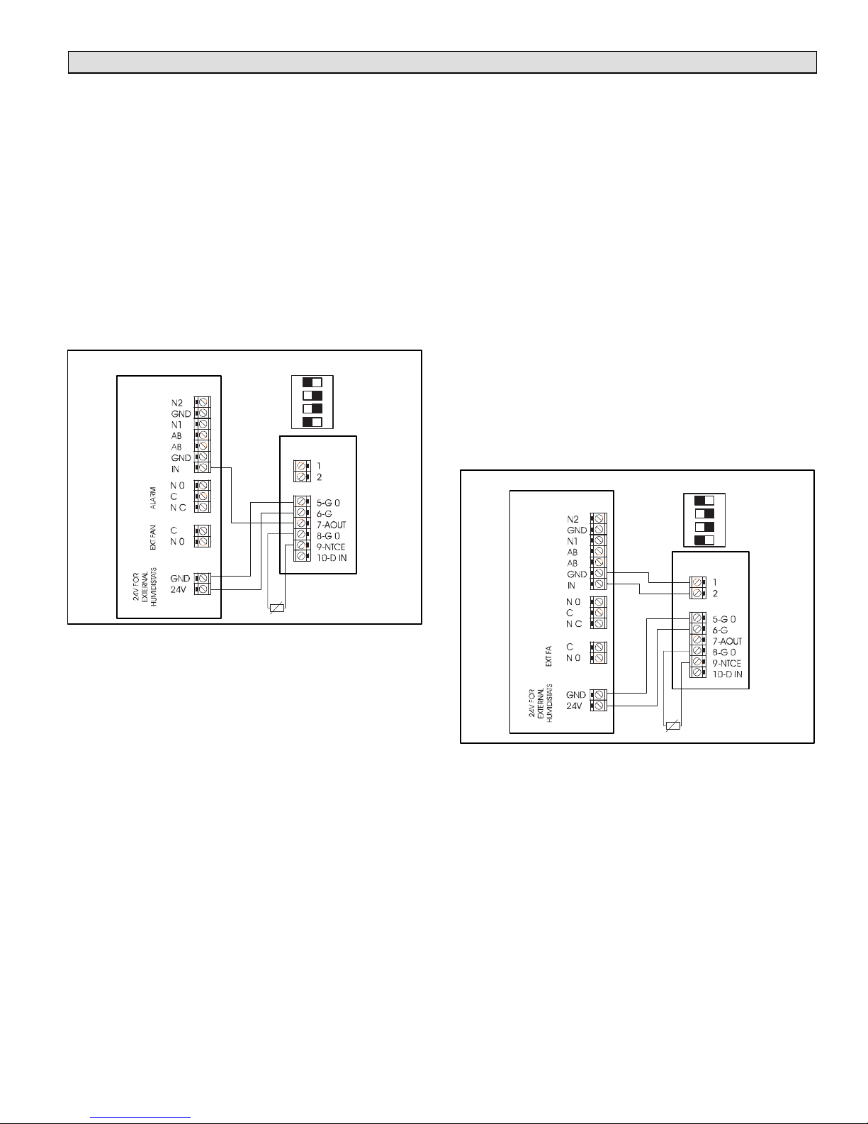
Electrical connections
Connect the HC Digital Automatic Humidistat to
HCSteam Humidifier for Modulating Operation
IMPORTANT - Be sure the connections are made as de
scribed in the following and as shown in figure 2.
1. Connect HCSteam Humidifier terminal 24V to HC Dig
ital Automatic Humidistat terminal 6-G.
2. Connect HCSteam Humidifier terminal GND to HC
Digital Automatic Humidistat terminal 5-G0.
3. Connect HCSteam Humidifier terminal IN to HC Digital
Automatic Humidistat terminal 7-AOUT.
NOTES -
S Modulating operation requires that the signal type be
changed at the HCSteam Humidifier. See HCSteam
Humidifier Installation Instruction Manual 506746-01.
S Verify DIP switch settings per figure 2.
DIP Switch
settings
HCSteam
Y3760
ON
OFF
OFF
ON
1 2 3 4
ON DP
Connect the HC Digital Automatic Humidistat
to HCSteam Humidifier for ON-OFF Operation
IMPORTANT - Be sure the connections are made as de
scribed in the following and as shown in figure 3.
1. Connect HCSteam Humidifier terminal 24V to HC Dig
ital Automatic Humidistat terminal 6-G.
2. Connect HCSteam Humidifier terminal GND to HC
Digital Automatic Humidistat terminal 5-G0.
3. Connect HCSteam Humidifier terminal GND to HC
Digital Automatic Humidistat terminal 1.
4. Connect HCSteam Humidifier terminal IN to HC Digital
Automatic Humidistat terminal 2.
Connect HCSteam Humidifier terminals 24V and GND to
HC Digital Automatic Humidistat terminals 6-G and 5-G0
respectively. Do not reverse these connections. Connect
HC Digital Automatic Humidistat terminal 1 and 2 to
HCSteam terminal GND and IN respectively. Do not re
verse these connections (see figure 3).
NOTES -
S HCSteam humidifiers are configured for On-OFF op
eration from the factory. See HCSteam Humidifier
Installation Instruction Manual 506746-01.
S Verify Dip Switch Settings per figure 3.
DIP Switch
HCSteam
settings
Y3760
ON
OFF
OFF
1 2 3 4
ON
ON DP
Outdoor Temp.
Sensor (if used)
Figure 2. Connect for Modulating Operation
Outdoor Temp.
Sensor (if used)
Figure 3. Connect for ON-OFF Operation
Page 3
HC SERIES
Page 4

Placement of Remote Outdoor Temperature
Sensor
S
Outdoor temperature sensor should not be mounted
on the south side of the house or in direct sunlight.
S Outdoor temperature sensor may not be located clos
er than 4 feet to exhaust vents, dryer vents, etc.
S If outdoor temperature sensor is mounted in fresh air
intake duct, make sure the probe is no further than 1
foot from outside wall.
Table 2. Outdoor Sensor Temperature / Resistance Range
S Make sure wiring for outdoor temperature sensor is
not close to other wires particularly high voltage.
S Outdoor temperature sensor must be at least 6” above
expected snow line.
S Maximum conductor length of the Outdoor Tempera
ture Sensor is 100 feet (30m) of standard thermostat
cable (twisted pair not required).
S Connect Outdoor Temperature Sensor to terminals #8
and #9.
Temperature
ºF (ºC)
-40.0 (-40) 196 188 181.1 41.0 (5) 22.5 22.1 21.7
-29.2 (-34) 142 137 131.8 50.0 (10) 18.2 18 17.7
-20.2 (-29) 109 106 102.2 60.8 (16) 14.3 14.1 13.9
-9.4 (-23) 80.7 78.3 75.93 69.8 (21) 11.8 11.6 11.6
-0.4 (-18) 63.3 61.5 59.81 80.6 (27) 9.38 9.28 9.18
10.4 (-12) 47.7 46.5 45.31 100.4 (38) 6.33 6.24 6.15
19.4 (-7) 37.9 37.1 36.2 122.0 (50) 4.24 4.16 4.08
30.2 (-1) 30 28.5 27.89 136.4 (58) 3.28 3.2 3.1
Maximum Standard Minimum Maximum Standard Minimum
Resistance Value (KOHM)
Temperature
ºF (ºC)
Resistance Value (KOHM)
506808-01 06/11
Page 4
Page 5

User Interface and Modes
Display and buttons
Figure 4 below shows the humidistat with its control but
tons and its display, along with a key of what each of the
symbols represent. Table 3 describes how the buttons op
erate.
side
programming
buttons
LCD display
immediately
change the current
set point
1 3 42
5
6
7
91011
Key:
1. LARGE field - Displays the temperature/humidity.
2. Displays setting for active value on the large display.
3. Night mode symbol. If off = daytime mode.
4. Lock mode. The parameter is not accessible.
5. Active time bands.
6. Outside/inside/maximum/minimum temperature symbol.
7. Displays setting for active value on the small display.
8. Auto operating mode.
9. SMALL field - Displays the temperature/humidity.
10. Dehum. (dehumidify) / humid. (humidify) operation. When the ramp
symbol is on, the corresponding mode is active.
11. HEAT COOL INDICATORS (NOT USED)
8
Figure 4. Humidistat display and buttons
Table 3. Humidistat buttons description
On/Off .
Selects the temperature display mode, degrees Celsius or Fahr
enheit. Whenever pressed switches the temperature units.
Used to display and where necessary change, using the UP and
DOWN buttons, the set point displayed in the SMALL field. If
held for more than 5 seconds, accesses the parameters menu.
To scroll the various parameters use UP and DOWN. To edit
them, press the SET button a second time and to exit the param
eters menu press the PRG button. Access to the parameters is
protected by password if parameter PS is enabled.
Change mode manually: activates the opposite function (and the
corresponding set point) to the current (night if day or day if
night), for the set time. To change or reset the timer use the UP
and DOWN buttons to increase or decrease the time. Press a
second time to exit and return to the main menu. If sleep mode
is already active, pressing the button shows the time remaining
on the timer.
E.g.: if the humidistat is in Night mode (moon symbol on) from
time band, pressing this button activates daytime mode (moon
symbol off ) for the set time.
Accesses the menu for setting the clock, the time bands, and the
default value of the timer. When first pressed, displays the cur
rent time (RTC); to display the other parameters, use the UP and
DOWN arrows. To set a new value, press SET when displaying
the desired parameter and change the value using the UP and
DOWN buttons. Press a second time to exit and return to the
main menu.
Accesses the menu for displaying the temperature: current,
maximum and minimum outside (from instrument power on),
inside and outside. To display the various temperatures, press
the button repeatedly. Their meaning is displayed in the box with
the home symbol.
Also displays the value of the analogue output when “Out” is
shown in the SMALL field.
From the main menu increases the value of the set point dis
played in the LARGE field. In the other menus displays the vari
ables or the parameters, or alternatively sets the value after
having pressed SET.
From the main menu decreases the value of the set point dis
played in the LARGE field. In the other menus displays the vari
ables or the parameters, or alternatively sets the value after
having pressed SET
The values displayed in the LARGE and SMALL fields
(shown in figure 4) depend on the setting of parameter dyS
as shown in table 4.
Table 4. dyS parameter values
dyS LARGE field (1) SMALL field (9)
1 humidity humidity set point
2 humidity set point humidity
3 humidity set point
4 humidity
Page 5
HC SERIES
Page 6

Configuration
NOTICE
Before closing the cover, the mode must be selected
using the dip switches.
Important: Setting the dip switches incorrectly will
cause the humidistat to malfunction.
Table 5. Setting humidistat control type
DIP switch positions
1 2 3 4
ON OFF OFF ON Humidifier Control (default)
ON OFF OFF OFF Dehumidifier Control
Setting parameter
The parameters for all operating modes also feature a de
fault value. These values can be restored by running the
“Factory set” operation. See the table of parameters for
details of the default values and settings.
S SET POINT: depending on the operating mode, differ
ent set points are used. To set these, access (SET but
ton – press and hold for 5 seconds) the mode for set
ting the parameters and set the corresponding values.
For the current mode only, the value can be accessed
directly using UP, DOWN or set, UP, DOWN (for the
SMALL field).
With the desired parameter displayed, use the UP/
DOWN buttons, then press SET - the parameter starts
flashing. Edit the value using the UP/DOWN buttons
and then press SET. To exit the menu, press the PRG
button again.
S Clock, TIME BANDS Prg/(clock): Press the corre
sponding button to display and if necessary set the de
fault duration of the change mode timer, display or set
the RTC clock and set the Day and Night time bands.
Initially, at least the set point for humidity control need
to be checked/set:
– Humidification set point (def. 30.0 % RH)
– Dehumidification set point (def. 70.0 % RH)
Humidistat is
set for:
rtC clock hh:mm -
SLP manual changeover duration def. 8 hours
dAy start day band def. 08:00
nIt start night band def. 20:00
S To disable the time bands function, set parameter rtC
off :
– Select parameter rtC using PRG/CLOCK and set
the value using the DOWN button.
– When reaching 00:00 using the DOWN button the
function will be off.
When parameter rtC is set to off the operating mode is al
ways daytime, and consequently only the daytime set
points are used, the night settings are only used when the
NIGHT button is pressed, manually changing mode.
Auto humidity control
In addition to the modes featured by the control algorithms,
the humidity can be controlled automatically, based on the
reading of the outside temperature sensor. The aim of this
type of control is to simplify the setting of the HC Digital
Automatic Humidistat, changing the humidity control ac
cording to the outside environmental conditions and there
fore minimize the discomfort of the user when moving into/
out of the air-conditioned environment This operating
mode is selected by setting parameter AUt (see table 7).
S According to the level set using the up/down buttons,
with a value from 1H to 7H, a different humidity set
point trend is defined. To disable this operating mode,
in the parameters menu set the value of AUt = 0.
AUTO mode for the humidification control is only pos
sible if the outside temperature sensor is installed.
– AUTO mode for the humidification control is only
possible if the outside temperature sensor is
installed.
Sensor Calibration
To make up for any errors due to the length of the cables or
the sensors connected, the controller features two param
eters for calibrating the values read by the sensors. The
CAL parameters are also shown in table 7.
Table 7. Auto humidity and calibration parameters
Code Description of the parameter Range Default
Table 6. Operating mode defaults
AUt
CAL+ Int
CAL+ ESt
CAL+ HUn
Humidity set point level compensated according to the outside temperature.
If humidity control is featured, the ambient humidity is controlled with an auto
matic set point, defined from 1H to 7H using the buttons, as specified in Table 8.
If set to OFF, the mode is disabled.
Setting one of the levels shown in the table, the controller independently sets a
humidity set point in relation to the outside temperature measurement
Inside temperature calibration, digital sensor or NTC (within a max. of ± 10°C) -10 to 10 0.0 °C
Outside temperature calibration, NTC sensor (within a max. of ± 10°C) -10 to 10 0.0 °C
Digital humidity sensor calibration(within a max. of ± 15°rH)
Within a maximum of ± 15% rH
OFF
1H to 7H
-15 to 15 0.0 %rH
OFF —
Unit of
measure
506808-01 06/11
Page 6
Page 7

Table 8. Humidity set point according to the setting of AUt (outside temperature in degrees)
AUt
Level
1H
2H
3H
4H
5H
6H
7H
-9.4°F
(-23°C)
10% 10% 10% 10% 15% 20% 25% 30%
10% 10% 10% 15% 20% 25% 30% 35%
10% 10% 15% 20% 25% 30% 35% 40%
10% 15% 20% 25% 30% 35% 40% 45%
10% 20% 25% 30% 35% 40% 45% 45%
10% 25% 30% 35% 40% 45% 45% 45%
10% 30% 35% 40% 45% 45% 45% 45%
-9.4 to 1.4°F
(-23 to -17°C)
1.4 to 10.4 °F
(-17 to -12°C)
10.4 to 21.2°F
(-12 to -6°C)
Functions
General
This section describes the humidity control modes avail
able. The control modes are based on parameters, divided
into two levels (see figure 5):
S Level 1, basic: main settings, always required;
S Level 2, advanced: used to customize the features of
the controller.
IMPORTANT - Some parameters included in the ad
vanced level, are forced to take on default values in the ba
sic level or are linked to other parameters in the basic level.
This especially applies to the control differentials. In each
operating mode, the links between the various basic and
advanced levels are specified.
S if level 1 is active, the level 2 parameters are not used
but rather replaced by the default values or by the link
value with the level 1 parameters;
S the level 2 parameters are effectively used when level
2 is activated.
Humidity control
This type of control is used to send a start signal to a hu
midifier or dehumidifier. The modulating output can only be
used for humidification control. Examples of using of the
analog output:
S for proportional humidity control of HCSteam humidifi
ers;
S as an additional step to the relay for humidity control.
(See the DIP switch settings in table 5, Page 6.)
Below
21.2 to 30.2°F
(-6 to -1°C)
LEVEL = 1
DIP 4 = ON DIP 4 = OFF
10 V
30.2 to 39.2°F
(-1 to 4°C)
Output Output
R2
39.2 to 50°F
(4 to 10°C)
50°F
(10°C)
R2
Above
0 V
dFH
Humidification setpoint Dehumidification setpoint
LEVEL = 2
DIP 4 = ON DIP 4 = OFF
10 V
R2 R2
0 V
dFH
dFH
dSA
Humidification setpoint Dehumidification setpoint
Output Output
% H.R
Figure 5. Level functions
Table 9. Humidity control indicators & defaults
Code Description Default Level
Humidification set point 50.0 % rH 1
Dehumidification set point 70.0 % rH 1
dFH Humidification differential 5.0 % rH 1
dFd Dehumidification differential 5.0 % rH 1
dFd% U.R
dFd
% U.R
% H.R
Page 7
HC SERIES
Page 8

Parameters
code parameter range default
Humidification set point. 10 to 70 50.0 % rH
Dehumidification set point. 10 to 70 70.0 % rH
unit of
measure
note
dFH
dFd Dehumidification differential activating relay. 1 to 20 5.0 % rH
SFH Humidification/dehumidification status in day and night mode. Acti
AUt Humidity set point automatically compensated by outside tempera
CAL+Int Inside temperature calibration, digital sensor or NTC.
CAL+ESt Outside temperature calibration, NTC sensor.
CAL+HUn Digital humidity sensor calibration.
Humidity differential for activating analog output and relay. 1 to 20 5.0 % rH
vates or deactivates humidification or dehumidification control (based on
DIP 4) with the time bands. The parameter can have the following three
values:
0 Time bands disabled. The humidification/dehumidification control is
always active, if featured, and is configured in relation to dip4.
1 Time bands enabled. When switching to the daytime band, humidifica
tion/dehumidification control (depends on dip4) is activated. When
switching to the night band, humidification/dehumidification control
(depends on dip4) is deactivated.
2 Time bands enabled. When switching to the daytime band, humidifica
tion/dehumidification control (depends on dip4) is deactivated. When
switching to the night band, humidification/dehumidification control
(depends on dip4) is activated.
ture. If humidity control is featured, the ambient humidity is controlled
with an automatic set point, defined from 1H to 7H using the buttons, as
specified in the corresponding table (see Page 6).
If set to OFF the mode is disabled.
Setting one of the levels in the table, the controller independently sets a
humidity set point in relation to the outside temperature.
Within a maximum of ± 10 °C.
Within a maximum of ± 10 °C.
Within a maximum of ± 15% rH.
0 to 2 0 —
OFF
1H to 7H
-10 to 10 0.0 °C
-10 to 10 0.0 °C
-15 to 15 0.0 % rH
OFF —
LE Parameter access level. Levels of access that control parameters for the
active mode:
1 Basic access: only the essential parameters for correct operation.
2 Advanced access: used to set all the parameters for the selected con
trol mode.
Unt Temperature display mode. Sets the temperature display mode, in de
grees Fahrenheit or Centigrade. Unlike direct selection using the button, if
changing the temperature display mode using parameter Unt, this be
comes the default display mode when switching the instrument on.
1, 2 1 —
°C, °F °C —
Alarms and Signals
code on large
field display
EE system/memory error manual by
Eth temperature+humidity sensor fault automatic stops all outputs and disables the calculation of the dewpoint
E1 built-in NTC temperature sensor fault automatic stops all outputs
E2 remote temperature sensor fault automatic tops compensation if active, and control on average if enabled
Ert RTC alarm automatic —
ALE external alarm from digital input automatic signal-only alarm from external contact (humidifier)
Note: When the value is not shown in the SMALL or LARGE field, three dashes “---“ are displayed.
description reset effect
stops all outputs
removing
power
506808-01 06/11
Page 8
Page 9

Technical Specifications
General
Power supply 24 Vac +10 to -15%, 50/60Hz, 1 VA
22 to 35 Vdc, 0.5W
Class 2 safety power supply
2
Min. cable cross-section 20 AWG (0.5 mm
Power supply compatible with HCSteam Humidifier (G – G0)
Operating temperature 0 to 60°C 32 to 140°F, 10 to 90% rH not-condensing
Storage temperature -20 to 70°C -4 to 158°F, 10 to 90% rH not-condensing
Precision of inside temperature measurement ± 1°C from 0 to 60°C, ± 2°C from 32 to 140°F
Precision of outside temperature measurement ± 1.5°C from 0 to 40°C ± 2.0°C from -40 to 0°C and 40 to 80°C
± 3°F from 32 to 104°F ± 4°F from -40 to 32°F and 104 to 176°F
0 to 10 V analog output, not isolated, for proportional
control
Relay approval 1 AMP @ 24 Vac
Precision of humidity measurement range 10 to 90% ± 3% rH at 25°C, 77°F
Dimensions 5.3x3.4x1.4” (135x86x36 mm)
precision ±5%
max load 5 kΩ, max current 2 mA
± 5% rH 0 to 60°C, 32 to 140°F
Wiring
Digital input Non-isolated version:direct connection of the voltage-free contact; contact closing
Outside temperature sensor connection with standard
sensor (10K 25°C β=3435):
Digital input connection Maximum length: 33' (10 m), min. cable cross-section 20 AWG (0.5 mm2).
Analog output connection Maximum length: 33' (10 m), min. cable cross-section 20 AWG (0.5 mm2).
Relay output connections: Maximum length 100' (30 m), cable cross-section from 16 to 13 AWG (1.5 to 2.5
UL specifications for connections:
Warning: All the connections, except for the relays, must be connected to very low voltage circuits with reinforced insulation.
current: 3 to 5 mA.
Maximum length: 100' (30 m), min. cable cross-section 20 AWG (0.5 mm2).
2
mm
), class 2 reinforced insulation from the instrument.
Use copper wires approved for a temperature of 75°C.
Minimum cross-section AWG 22-14 rigid or flexible.
To tighten the terminals, apply a torque of 7 Lb/In for the black terminals (SAU
RO).
To use the instrument in compliance with UL-873, a load with a maximum voltage
24 Vac, class 2, can be connected to the relay output.
).
Replacement Parts
Outdoor Temperature Sensor Cat. No. Y4103
Contact your local Lennox dealer to order replacement parts. For the Lennox dealer nearest you, dial 1-800-9-Lennox. Visit
us at http://www.Lennox.com
Page 9
HC SERIES
Page 10

+070220641
Rel. 1.0 - June 2011
506808-01 06/11
Page 10
 Loading...