

Lennox XP19, Signature XP19-024, Signature XP19-036, Signature XP19-048, Signature XP19-060 Installation Instructions Manual
Page 1
INSTALLATION
E2009 Lennox Industries Inc.
Dallas, Texas, USA
RETAIN THESE INSTRUCTIONS
FOR FUTURE REFERENCE
WARNING
Improper installation, adjustment, alteration,
service or maintenance can cause personal injury,
loss of life, or damage to property.
Installation and service must be performed by a
licensed professional installer (or equivalent) or a
service agency.
CAUTION
Physical contact with metal edges and corners
while applying excessive force or rapid motion can
result in personal injury. Be aware of, and use
caution when working near these areas during
installation or while servicing this equipment.
INSTRUCTIONS
Dave Lennox Signature
Collection XP19 Series
Units
HEAT PUMPS
505,331M
06/09
Supersedes 05/09
Table of Contents
Shipping and Packing List 1. . . . . . . . . . . . . . . . . . . . . .
Unit Dimensions 2. . . . . . . . . . . . . . . . . . . . . . . . . . . . . . .
XP19 Heat Pumps 2. . . . . . . . . . . . . . . . . . . . . . . . . . . . .
General Information 2. . . . . . . . . . . . . . . . . . . . . . . . . . .
Recovering Refrigerant from Existing System 4. . . . .
Removing Existing Outdoor Unit 5. . . . . . . . . . . . . . . . .
Positioning New Outdoor Unit 5. . . . . . . . . . . . . . . . . . .
Removing Panels 6. . . . . . . . . . . . . . . . . . . . . . . . . . . . .
New or Replacement Line Set 8. . . . . . . . . . . . . . . . . . .
Brazing Connections 9. . . . . . . . . . . . . . . . . . . . . . . . . . .
Removing Indoor Unit Metering Device 10. . . . . . . . . . .
Flushing the System 11. . . . . . . . . . . . . . . . . . . . . . . . . . .
Installing New Indoor Unit Metering Device 12. . . . . . . .
Testing for Leaks 12. . . . . . . . . . . . . . . . . . . . . . . . . . . . . .
Evacuating the System 14. . . . . . . . . . . . . . . . . . . . . . . . .
Servicing Unit Delivered Void of Charge 15. . . . . . . . . .
Electrical Connections 16. . . . . . . . . . . . . . . . . . . . . . . . .
Start−Up and Charging Procedures 16. . . . . . . . . . . . . . .
System Operations 21. . . . . . . . . . . . . . . . . . . . . . . . . . . .
Lennox System Operation Monitor (LSOM) 21. . . . . . .
Defrost System 24. . . . . . . . . . . . . . . . . . . . . . . . . . . . . . .
Maintenance 29. . . . . . . . . . . . . . . . . . . . . . . . . . . . . . . . . .
Two−Stage Compressor Check−out 30. . . . . . . . . . . . . . .
Homeowner Information 30. . . . . . . . . . . . . . . . . . . . . . . .
Field Operational Checklist 32. . . . . . . . . . . . . . . . . . . . .
Start−up and Performance Checklist 32. . . . . . . . . . . . . .
Shipping and Packing List1
®
Litho U.S.A.
IMPORTANT
This unit must be matched with an indoor coil as
specified in Lennox’ Engineering Handbook.
Coils previously charged with HCFC−22 must be
flushed.
IMPORTANT
The Clean Air Act of 1990 bans the intentional
venting of refrigerant (CFCs, HCFCs AND HFCs) as
of July 1, 1992. Approved methods of recovery,
recycling or reclaiming must be followed. Fines
and/or incarceration may be levied for
noncompliance.
06/09 505,331M
*2P0609* *P505331M*
Check the unit for shipping damage and listed times below
are intact. If damaged, or if parts are missing, immediately
contact the last shipping carrier.
1 Assembled outdoor unit.
1 Bag assembly which contains the followings:
1 Bushing (for low voltage wiring
2 Isolation grommets for liquid and suction lines
ISOLATION GROMMETS (2)
Figure 1. Bag Assembly (Parts)
Page 1
BUSHING (1)
Page 2
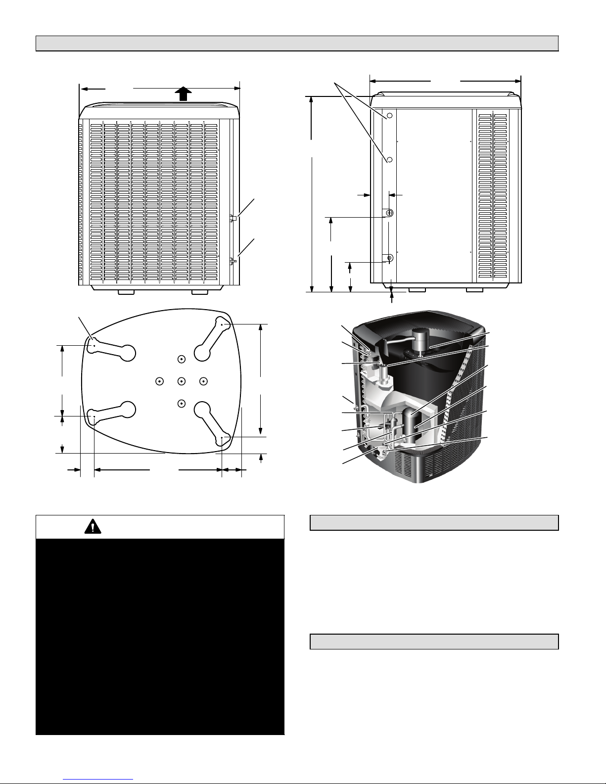
Unit Dimensions −− Inches (mm)2
UNIT SUPPORT
FEET
16−7/8
(429)
8−3/4
(222)
3−1/8
(79)
39−1/2
(1003)
DISCHARGE AIR
SIDE VIEW
30−3/4
(781)
SUCTION LINE
INLET
LIQUID LINE
INLET
26−7/8
(683)
3−3/4 (95)
4−5/8
(117)
ELECTRICAL
INLETS
37 (940) [−024, −036]
47 (1194) [−048, −060]
18−1/2
(470)
CONTACTOR
DEFROST
CONTROL
SYSTEM
OPERATION
MONITOR
VAPOR VALVE
AND GAUGE
PORT
DISCHARGE
LINE
REVERSING
VALV E
VAPOR LINE
FILTER DRIER
4−1/2
(114)
8 (203)
1 (25)
35−1/2
(902)
ACCESS VIEW
OUTDOOR FAN
RUN
CAPACITOR
TWO−STAGE
COMPRESSOR
COMPRESSOR
TERMINAL
PLUG
LOW
PRESSURE
SWITCH
HIGH
PRESSURE
SWITCH
BASE
WARNING
This product and/or the indoor unit it is matched
with may contain fiberglass wool.
Disturbing the insulation during installation,
maintenance, or repair will expose you to fiberglass
wool dust. Breathing this may cause lung cancer.
(Fiberglass wool is known to the State of California
to cause cancer.)
Fiberglass wool may also cause respiratory, skin,
and eye irritation.
To reduce exposure to this substance or for further
information, consult material safety data sheets
available from address shown below, or contact
your supervisor.
Lennox Industries Inc.
P.O. Box 799900
Dallas, TX 75379−9900
505331M 06/09
XP19 PARTS ARRANGEMENT
XP19 Heat Pumps3
The XP19 Heat Pumps, which will also be referred to in this
instruction as the outdoor unit, uses HFC−410A
refrigerant. This outdoor unit must be installed with a
matching indoor unit and line set as outlined in the Lennox
XP19 Engineering Handbook.
This outdoor unit is designed for use in systems that use
check thermal expansion valve (CTXV) refrigerant
metering devices.
General Information4
These instructions are intended as a general guide and do
not supersede local codes in any way. Consult authorities
who have jurisdiction before installation.
When servicing or repairing HVAC components, ensure
the fasteners are appropriately tightened. Table 1 shows
torque values for fasteners.
Page 2
Page 3
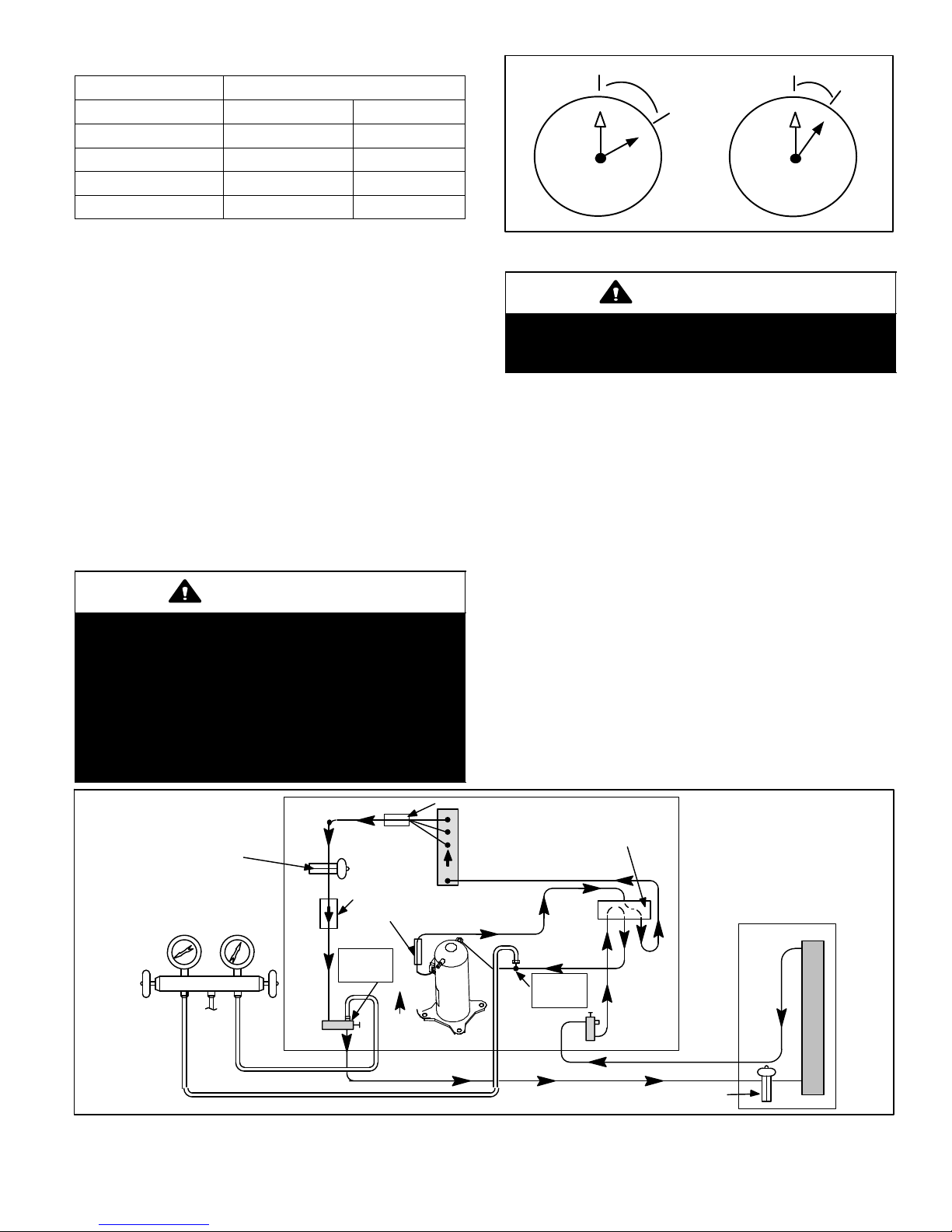
Table 1. Torque Requirements
Parts Recommended Torque
Service valve cap 8 ft.− lb. 11 NM
Sheet metal screws 16 in.− lb. 2 NM
Machine screws #10 28 in.− lb. 3 NM
Compressor bolts 90 in.− lb. 10 NM
Gauge port seal cap 8 ft.− lb. 11 NM
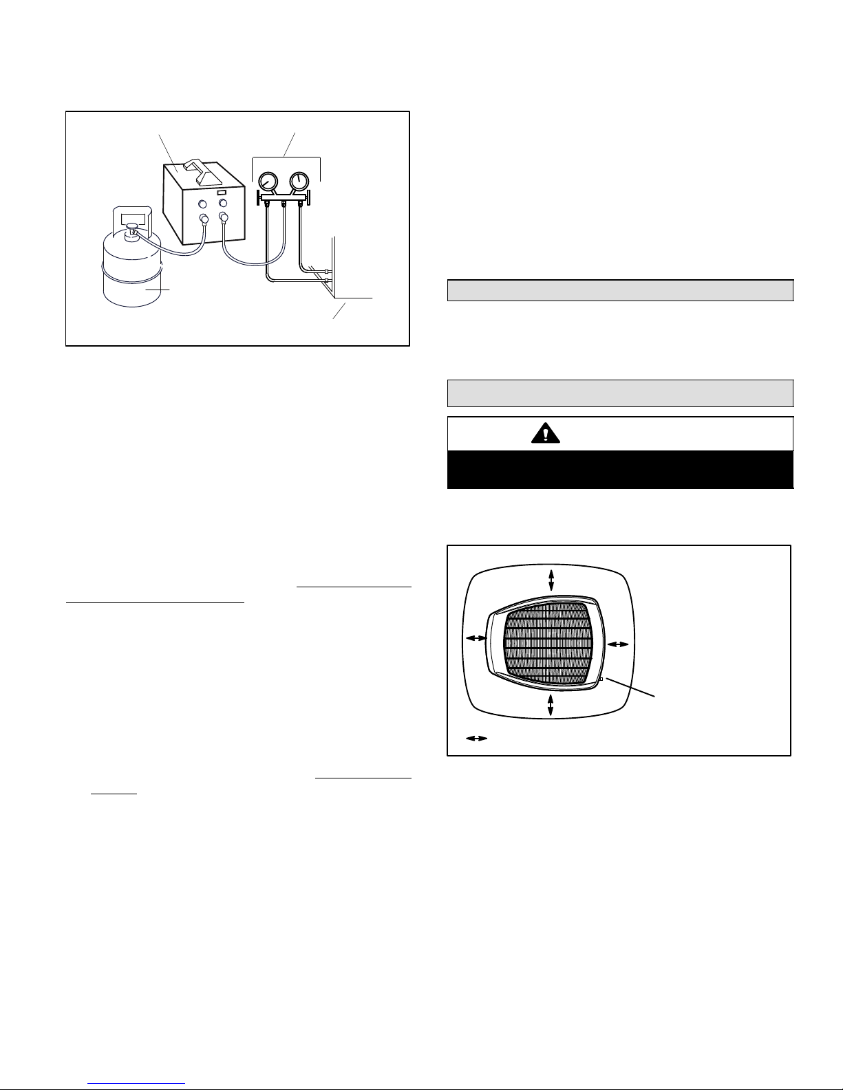
USING MANIFOLD GAUGE SETS
When checking the system charge, only use a manifold
gauge set that features low loss anti−blow back fittings.
See Figure 3 for a typical manifold gauge connection
setup.
Manifold gauge sets used with HFC−410A refrigerant
systems must be capable of handling the higher system
operating pressures. The gauges should be rated for use
with pressures of 0 − 800 on the high side and a low side of
30" vacuum to 250 psi with dampened speed to 500 psi.
Gauge hoses must be rated for use at up to 800 psi of
pressure with a 4000 psi burst rating.
OPERATING SERVICE VALVES
The liquid and vapor line service valves are used for
removing refrigerant, flushing, leak testing, evacuating,
checking charge and charging.
Each valve is equipped with a service port which has a
factory−installed valve stem.
IMPORTANT
Only use Allen wrenches of sufficient hardness
(50Rc − Rockwell Harness Scale minimum). Fully
insert the wrench into the valve stem recess.
Service valve stems are factory−torqued (from 9
ft−lbs for small valves, to 25 ft−lbs for large valves) to
prevent refrigerant loss during shipping and
handling. Using an Allen wrench rated at less than
50Rc risks rounding or breaking off the wrench, or
stripping the valve stem recess.
1/12 TURN
12
1
2
3
4
7
5
6
9
10
8
11
1/6 TURN
12
1
2
3
4
7
5
6
11
10
9
8
Figure 2. Cap Tightening Distances
IMPORTANT
To prevent stripping of the various caps used, the
appropriately sized wrench should be used and
fitted snugly over the cap before tightening.
To Access Angle−Type Service Port:
A service port cap protects the service port core from
contamination and serves as the primary leak seal.
1. Remove service port cap with an appropriately sized
wrench.
2. Connect gauge to the service port.
3. When testing is completed, replace service port cap and
tighten as follows:
D With Torque Wrench: Finger tighten and then
tighten per Table 1.
D Without Torque Wrench: Finger tighten and use an
appropriately sized wrench to turn an additional
1/6 turn clockwise as illustrated in Figure 2.
To Open and Close Angle−Type Service Valve:
A valve stem cap protects the valve stem from
contamination and assures a leak−free seal.
1. Remove stem cap with an appropriately sized wrench.
2. Use a service wrench with a hex−head extension
(3/16" for liquid-line valve sizes and 5/16" for
vapor-line valve sizes) to back the stem out
counterclockwise as far as it will go.
CHECK
EXPANSION VALVE
LOW
PRESSURE
GAUGE MANIFOLD
PRESSURE
TO
HFC−410
A DRUM
HIGH
LIQUID
LINE
VALV E
Figure 3. Typical Manifold Gauge Connection Setup
BI−FLOW
FILTER /
DRIER
MUFFLER
LIQUID
SERVICE
PORT
DISTRIBUTOR
OUTDOOR
COIL
COMPRESSOR
Page 3
HEAT PUMP
REVERSING VALVE
VAPOR
SERVICE
PORT
NOTE − Arrows indicate direction
of refrigerant flow.
VAPOR
LINE
VALV E
CHECK EXPANSION VALVE
INDOOR
COIL
XP19 SERIES
Page 4
3. Replace the stem cap and tighten as follows:
D With Torque Wrench: Tighten finger tight and then
tighten per Table 1.
D Without Torque Wrench: Finger tighten and use an
appropriately sized wrenched to turn an additional
1/12 turn clockwise as illustrated in Figure 2.
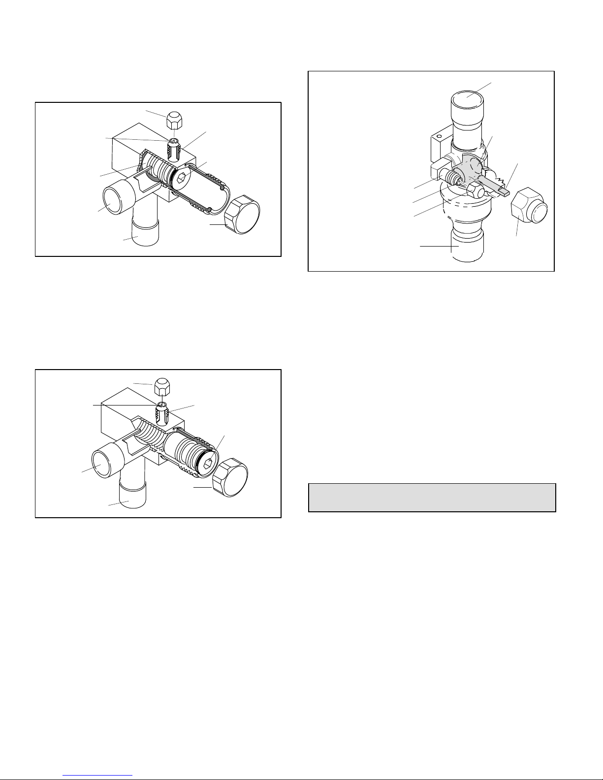
SERVICE PORT
CORE
VALVE STEM
FRONT-SEATED
TO INDOOR
UNIT
TO OUTDOOR UNIT
SERVICE PORT
CAP
SERVICE PORT
(VALVE STEM SHOWN
CLOSED) INSERT HEX
WRENCH HERE
STEM CAP
CLOSED TO BOTH INDOOR
AND OUTDOOR UNITS
Figure 4. Angle−Type Service Valve
(Font−Seated Closed)
NOTE A label with specific torque requirements may be
affixed to the stem cap. If the label is present, use the
specified torque.
NOTE To prevent stripping of the cap, the wrench
should be appropriately sized and fit snugly over the cap
before tightening the cap.
SERVICE PORT CAP
SERVICE PORT
CORE
OPEN TO BOTH
INDOOR AND
OUTDOOR UNITS
TO INDOOR
UNIT
TO OUTDOOR UNIT
STEM CAP
SERVICE PORT
(VALVE STEM SHOWN OPEN)
INSERT HEX WRENCH HERE
Figure 5. Angle−Type Service Valve
(Back−Seated Opened)
To Access Ball−Type Service Port:
A service port cap protects the service port core from
contamination and serves as the primary leak seal.
1. Remove service port cap with an appropriately sized
wrench.
2. Connect gauge to the service port.
3. When testing is completed, replace service port cap and
tighten as follows:
D With Torque Wrench: Finger tighten and then
tighten per Table 1.
D Without Torque Wrench: Finger tighten and use an
appropriately sized wrench to turn an additional
1/6 turn clockwise as illustrated in Figure 2.
OPEN TO LINE SET WHEN VALVE IS CLOSED,
TO BOTH LINE SET AND UNIT WHEN VALVE IS
OPEN.
TO OPEN ROTATE STEM
COUNTERCLOCKWISE 90°.
TO CLOSE ROTATE STEM
CLOCKWISE 90°.
SERVICE PORT
SERVICE PORT
CORE
SERVICE PORT CAP
TO OUTDOOR UNIT
TO INDOOR UNIT
BALL (SHOWN
CLOSED)
STEM CAP
VALV E
STEM
Figure 6. Ball−Type Service Valve
To Open and Close Ball−Type Service Valve:
A valve stem cap protects the valve stem from
contamination and assures a leak−free seal.
1. Remove stem cap with an appropriately sized wrench.
2. Use an appropriately sized wrenched to open. To open
valve, roate stem counterclockwise 90°. To close
rotate stem clockwise 90°.
3. Replace the stem cap and tighten as follows:
D With Torque Wrench: Finger tighten and then
tighten per Table 1.
D Without Torque Wrench: Finger tighten and use an
appropriately sized wrench to turn an additional
1/12 turn clockwise as illustrated in Figure 2.
NOTE A label with specific torque requirements may be
affixed to the stem cap. If the label is present, use the
specified torque.
Recovering Refrigerant from Existing
System5
Remove existing HCFC−22 refrigerant using one of the
following procedures:
METHOD 1:
If the existing outdoor unit is not equipped with shut−off
valves, or if the unit is not operational and you plan to use
the existing HCFC−22 to flush the system.
NOTE Use recovery machine instructions for specific
setup requirements.
1. Disconnect all power to the existing outdoor unit.
2. Connect to the existing unit a gauge set, clean
recovery cylinder and a recovery machine. Use the
instructions provided with the recovery machine on
how to setup the connections.
505331M 06/09
Page 4
Page 5
3. Remove all HCFC−22 refrigerant from the existing
system. Check gauges after shutdown to confirm that
the entire system is completely void of refrigerant.
RECOVERY MACHINE
CLEAN RECOVERY
CYLINDER
MANIFOLD GAUGES
OUTDOOR UNIT
Figure 7. Typical Refrigerant Recovery
(Method 1)
NOTE Use recovery machine instructions for specific
setup requirements.
METHOD 2:
Use this method if the existing outdoor unit is equipped
with manual shut−off valves, and plan on using new
HCFC−22 refrigerant to flush the system.
IMPORTANT: Some system configurations may contain
higher than normal refrigerant charge due to either large
internal coil volumes, and/or long line sets. The following
conditions may cause the compressor to stop functioning:
The following devices could prevent full system charge
recovery into the outdoor unit:
S Outdoor unit’s high or low−pressure switches (if
applicable) when tripped can cycled the compressor
OFF.
S Compressor can stop pumping due to tripped internal
pressure relief valve.
S Compressor has internal vacuum protection that is
designed to unload the scrolls (compressor stops
pumping) when the pressure ratio meets a certain
value or when the suction pressure is as high as 20
psig. (Compressor suction pressures should never be
allowed to go into a vacuum. Prolonged operation at
low suction pressures will result in overheating of the
scrolls and permanent damage to the scroll tips, drive
bearings and internal seals).
Once the compressor can not pump down to a lower
pressure due to one of the above system conditions, shut
off the suction valve. Turn OFF the main power to unit and
use a recovery machine to recover any refrigerant left in
the indoor coil and line set.
Perform the following task:
1. Start the existing HCFC−22 system in the cooling
mode and close the liquid line valve.
2. Pump as much of the existing HCFC−22 refrigerant
with the compressor back into the outdoor unit until
you have reached the limitations of the outdoor
system. Turn the outdoor unit main power OFF and
use a recovery machine to remove the remaining
refrigerant in the system.
NOTE It may be necessary to bypass the low pressure
switches if equipped to ensure complete refrigerant
evacuation.
3. When the low side system pressures reach 0 psig,
close the suction line valve.
4. Check gauges after shutdown to confirm that the
valves are not allowing refrigerant to flow back into the
low side of the system.
Removing Existing Outdoor Unit6
Perform the following task at the existing outdoor unit:
S Disconnect line set at the service valves.
S Disconnect electrical service at the disconnect switch.
S Remove old outdoor unit.
Positioning New Outdoor Unit7
CAUTION
In order to avoid injury, take proper precaution when
lifting heavy objects.
See Unit Dimensions on page 3 for sizing mounting slab,
platforms or supports. Refer to Figure 8 for mandatory
installation clearance requirements.
CONTROL PANEL
ACCESS LOCATION
SEE NOTES BELOW THIS FIGURE FOR FURTHER DETAILS.
Figure 8. Installation Clearances
NOTES:
S Service clearance of 30 in. (762 mm) must be
maintained on one of the sides adjacent to the control
box.
S Clearance to one of the other three sides must be 36
in. (914 mm)
S Clearance to one of the remaining two sides may be
12 in. (305 mm) and the final side may be 6 in. (152
.
mm)
S 48 in. (1219 mm) clearance required on top of unit.
S A clearance of 24 in. (610 mm) must be maintained
between two units.
.
Page 5
XP19 SERIES
Page 6
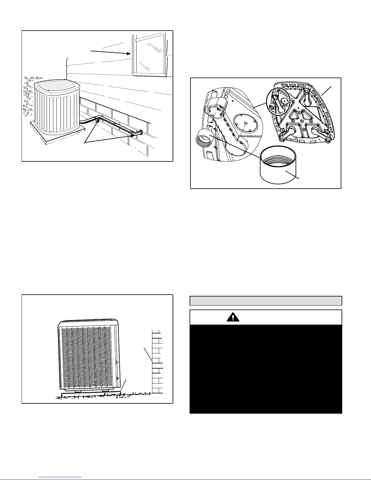
POSITIONING CONSIDERATIONS
INSTALL UNIT AWAY
FROM WINDOWS
TWO 90° ELBOWS INSTALLED
IN LINE SET WILL REDUCE
LINE SET VIBRATION.
Figure 9. Outside Unit Placement
Consider the following when positioning the unit:
S Some localities are adopting sound ordinances based
on the unit’s sound level registered from the adjacent
property, not from the installation property. Install the
unit as far as possible from the property line.
S When possible, do not install the unit directly outside
a window. Glass has a very high level of sound
transmission. For proper placement of unit in relation
to a window see the provided illustration in Figure 9.
PLACING UNIT ON SLAB
When installing unit at grade level, the top of the slab
should be high enough above grade so that water from
higher ground will not collect around the unit. The slab
should have a slope tolerance as described in Figure 10.
NOTE If necessary for stability, anchor unit to slab as
described in Stabilizing Unit on Uneven Surfaces on page
7.
ELEVATING THE UNIT
This unit is outfitted with elongated support feet as
illustrated in Figure 11 which uses a similar method for
elevating the unit.
BASE
LEG DETAIL
2" (50.8MM) SCH 40
FEMALE THREADED
ADAPTER
Figure 11. Elevated Slab Mounting using Feet
Extenders
If additional elevation is necessary, raise the unit by
extending the length of the unit support feet. This may be
achieved by using a 2" SCH 40 female threaded adapter.
The specified coupling will fit snuggly into the recessed
portion of the feet. Use additional 2" SCH 40 male threaded
adaptors which can be threaded into the female threaded
adaptors to make additional adjustments to the level of the
unit.
NOTE Keep the height of extenders short enough to
ensure a sturdy installation. If it is necessary to extend
further, consider a different type of field−fabricated
framework that is sturdy enough for greater heights.
INSTALL UNIT LEVEL OR, IF ON A SLOPE, MAINTAIN SLOPE
TOLERANCE OF 2 DEGREES (OR 2 INCHES PER 5 FEET [50 MM
PER 1.5 M]) AWAY FROM BUILDING STRUCTURE.
STRUCTURE
GROUND
LEVEL
Figure 10. Slab Mounting at Ground Level
505331M 06/09
BUILDING
MOUNTING
SLAB
Removing and Installing Panels8
CAUTION
To prevent personal injury, or damage to panels,
unit or structure, be sure to observe the following:
While installing or servicing this unit, carefully stow
all removed panels out of the way, so that the panels
will not cause injury to personnel, nor cause
damage to objects or structures nearby, nor will the
panels be subjected to damage (e.g., being bent or
scratched).
While handling or stowing the panels, consider any
weather conditions, especially windy conditions,
that may cause panels to be blown around and
battered.
Page 6
Page 7
WARNING
Unit must be grounded in accordance
with national and local codes.
Electric Shock Hazard. Can cause
injury or death.
Line voltage is present at all
components when unit is not in
operation on units with single-pole
contactors. Disconnect all remote
electric power supplies before
opening access panel. Unit may have
multiple power supplies.
IMPORTANT! DO NOT ALLOW
PANELS TO HANG ON UNIT BY TOP
TAB. TAB IS FOR ALIGNMENT AND
NOT DESIGNED TO SUPPORT
WEIGHT OF PANEL.
PANEL SHOWN SLIGHTLY
ROTATED TO ALLOW TOP TAB TO
EXIT (OR ENTER) TOP SLOT FOR
REMOVING (OR INSTALLING)
PANEL.
SCREW
HOLES
LIP
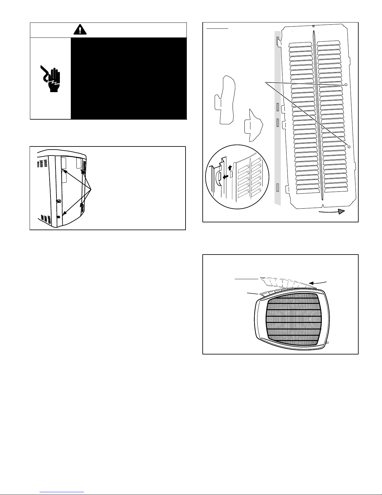
ACCESS PANEL
Removal and reinstallation of the access panel is
illustrated in Figure 12.
REMOVE 4 SCREWS TO REMOVE PANEL FOR
ACCESSING COMPRESSOR AND CONTROLS.
INSTALL BY POSITIONING PANEL WITH HOLES
ALIGNED; INSTALL SCREWS AND TIGHTEN.
Figure 12. Access Panel
LOUVERED PANELS
Remove the louvered panels as follows:
1. Remove two screws, allowing the panel to swing open
slightly.
2. Hold the panel firmly throughout this procedure.
Rotate bottom corner of panel away from hinged
corner post until lower three tabs clear the slots as
illustrated in Figure 13, detail B.
3. Move panel down until lip of upper tab clears the top
slot in corner post as illustrated in Figure 13, detail A.
Position and Install PanelPosition the panel almost
parallel with the unit as illustrated in Figure 14, detail D with
the screw side as close to the unit as possible. Then, in a
continuous motion:
S Slightly rotate and guide the lip of top tab inward as
illustrated in Figure 13, details A and C; then upward
into the top slot of the hinge corner post.
S Rotate panel to vertical to fully engage all tabs.
S Holding the panel’s hinged side firmly in place, close
the right−hand side of the panel, aligning the screw
holes.
When panel is correctly positioned and aligned, insert the
screws and tighten.
Detail A
Detail B
Detail C
ROTATE IN THIS DIRECTION;
THEN DOWN TO REMOVE PANEL
Figure 13. Removing/Installing Louvered Panels
(Detail A, B and C)
MAINTAIN MINIMUM PANEL ANGLE (AS CLOSE TO PARALLEL WITH THE UNIT
AS POSSIBLE) WHILE INSTALLING PANEL.
ANGLE MAY BE TOO
EXTREME
PREFERRED ANGLE
FOR INSTALLATION
HOLD DOOR FIRMLY ALONG
THE HINGED SIDE TO MAINTAIN
FULLY−ENGAGED TABS
Detail D
Figure 14. Removing/Installing Louvered Panels
(Detail D)
STABILIZING UNIT ON UNEVEN SURFACES
With unit positioned at installation site, remove two side
louvered panels to expose the unit base pan. Install the
brackets as illustrated in Figure 15 using conventional
practices; replace the panels after installation is complete.
Page 7
XP19 SERIES
Page 8
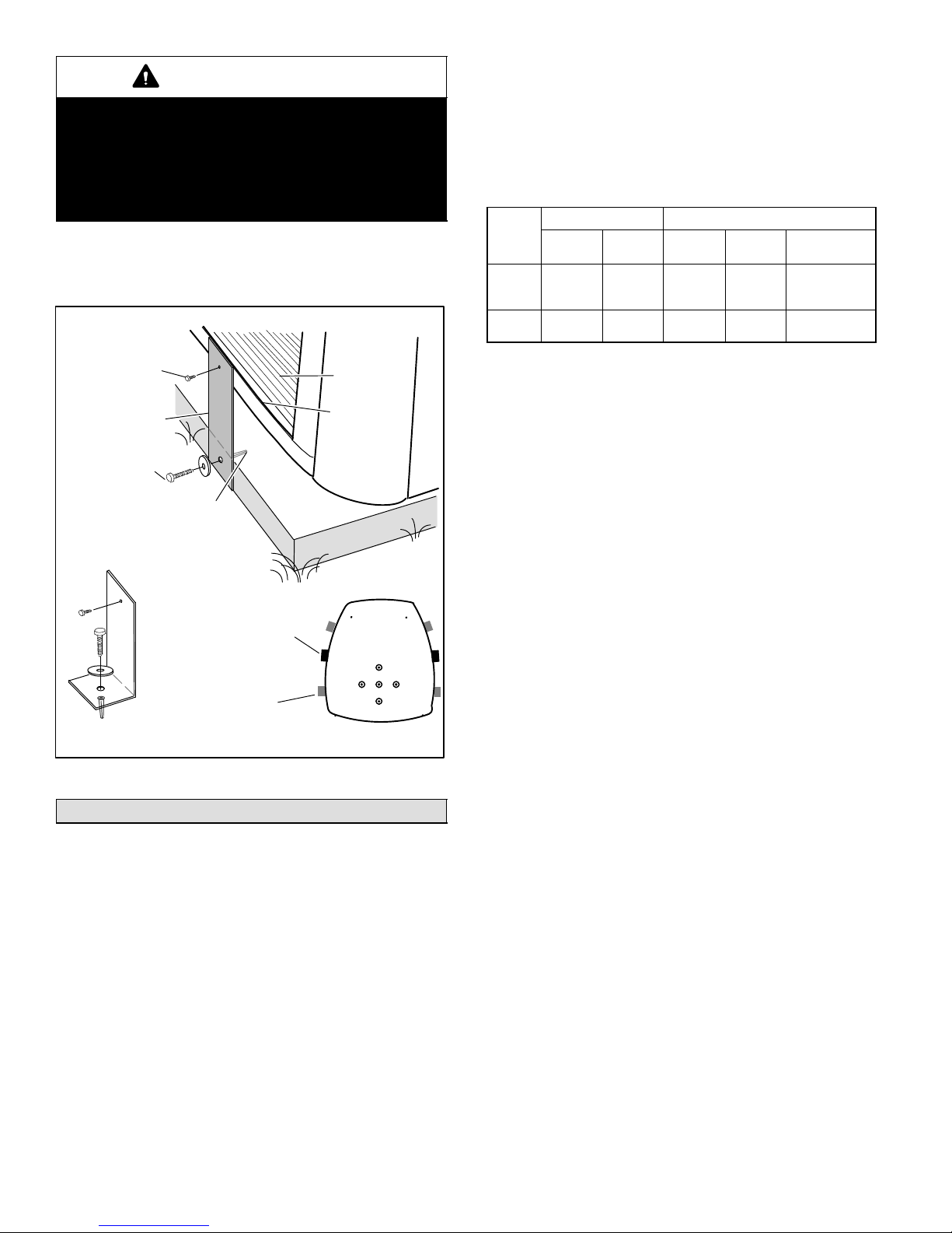
IMPORTANT
Unit Stabilizer Bracket Use (field−provided):
Always use stabilizers when unit is raised above the
factory height. (Elevated units could become
unstable in gusty wind conditions).
Stabilizers may be used on factory height units
when mounted on unstable an uneven surface.
To help stabilize an outdoor unit, some installations may
require strapping the unit to the pad using brackets and
anchors commonly available in the marketplace.
Slab Side Mounting
REFRIGERANT LINE SET
Field refrigerant piping consists of liquid and suction lines
from the outdoor unit (braze connections) to the indoor unit
coil (flare or sweat connections). Use Lennox L15 (sweat,
non−flare) series line set, or use field−fabricated refrigerant
lines as listed in Table 2.
Table 2. Refrigerant Line Set
Field Connections Recommended Line Set
Model
−024
−036
−048
−060
Liquid
Line
3/8".
(10 mm)
3/8".
(10 mm)
Suction
Line
7/8"
(22 mm)
1−1/8".
(29 mm)
Liquid
Line
3/8"
(10 mm)
3/8"
(10 mm)
Suction
Line
7/8"
(22 mm)
1−1/8"
(29 mm)
L15 Line Set
L15−65
15 ft. − 50 ft.
(4.6 m − 15 m)
Field
Fabricated
#10 1/2" LONG SELF−
DRILLING SHEET
METAL SCREWS
STABILIZING
BRACKET (18 GAUGE
METAL − 2" WIDTH;
HEIGHT AS REQ’D)
#10 1−1/4" LONG
HEX HD SCREW
AND FLATWASHER
CONCRETE SLAB − USE PLASTIC
PLASTIC ANCHOR (HOLE DRILL
1/4")PLASTIC SLAB − NO PLASTIC
ANCHOR (HOLE DRILL 1/8")
COIL
BASE PAN
CORNER POST
Deck Top
Mounting
STABILIZING BRACKET
(18 GAUGE METAL − 2"
WIDTH; HEIGHT AS
REQ’D); BEND TO FORM
RIGHT ANGLE
FOR EXTRA
ONE BRACKET PER SIDE (MIN.); FOR EXTRA STABILITY,
2 BRACKETS PER SIDE, 2" FROM EACH CORNER.
STABILITY
MINIMUM 1
PER SIDE
Figure 15. Installing Stabilizer Brackets
New or Replacement Line Set9
This section provides information on installation or
replacement of existing line set. If line set are not being
installed then proceed to Brazing Connections on page 12.
If refrigerant lines are routed through a wall, seal and
isolate the opening so vibration is not transmitted to the
building. Pay close attention to line set isolation during
installation of any HVAC system. When properly isolated
from building structures (walls, ceilings. floors), the
refrigerant lines will not create unnecessary vibration and
subsequent sounds. Also, consider the following when
placing and installing a high−efficiency air conditioner.
NOTE When installing refrigerant lines longer than 50
feet, see the Lennox Refrigerant Piping Design and
Fabrication Guidelines, or contact Lennox Technical
Support Product Applications for assistance. To obtain the
correct information from Lennox, be sure to communicate
the following points:
S Model (XP19) and size of unit (e.g. −060).
S Line set diameters for the unit being installed as listed
in Table 2 and total length of installation.
S Number of elbows and if there is a rise or drop of the
piping.
MATCHING WITH NEW OR EXISTING INDOOR COIL
AND LINE SET
The RFC1−metering line consisted of a small bore copper
line that ran from condenser to evaporator coil. Refrigerant
was metered into the evaporator by utilizing
temperature/pressure evaporation effects on refrigerant in
the small RFC line. The length and bore of the RFC line
corresponded to the size of cooling unit.
If the XP19 is being used with either a new or existing
indoor coil which is equipped with a liquid line which served
as a metering device (RFCI), the liquid line must be
replaced prior to the installation of the XP19 unit. Typically
a liquid line used to meter flow is 1/4" in diameter and
copper.
INSTALLING LINE SET
Line Set Isolation This reference illustrates
procedures, which ensure proper refrigerant line set
isolation:
S Installation of line set on horizontal runs is
illustrated in Figure 16.
S Installation of line set on vertical runs is illustrated in
Figure 17.
S Installation of a transition from horizontal to
vertical is illustrated in Figure 18.
505331M 06/09
Page 8
Page 9
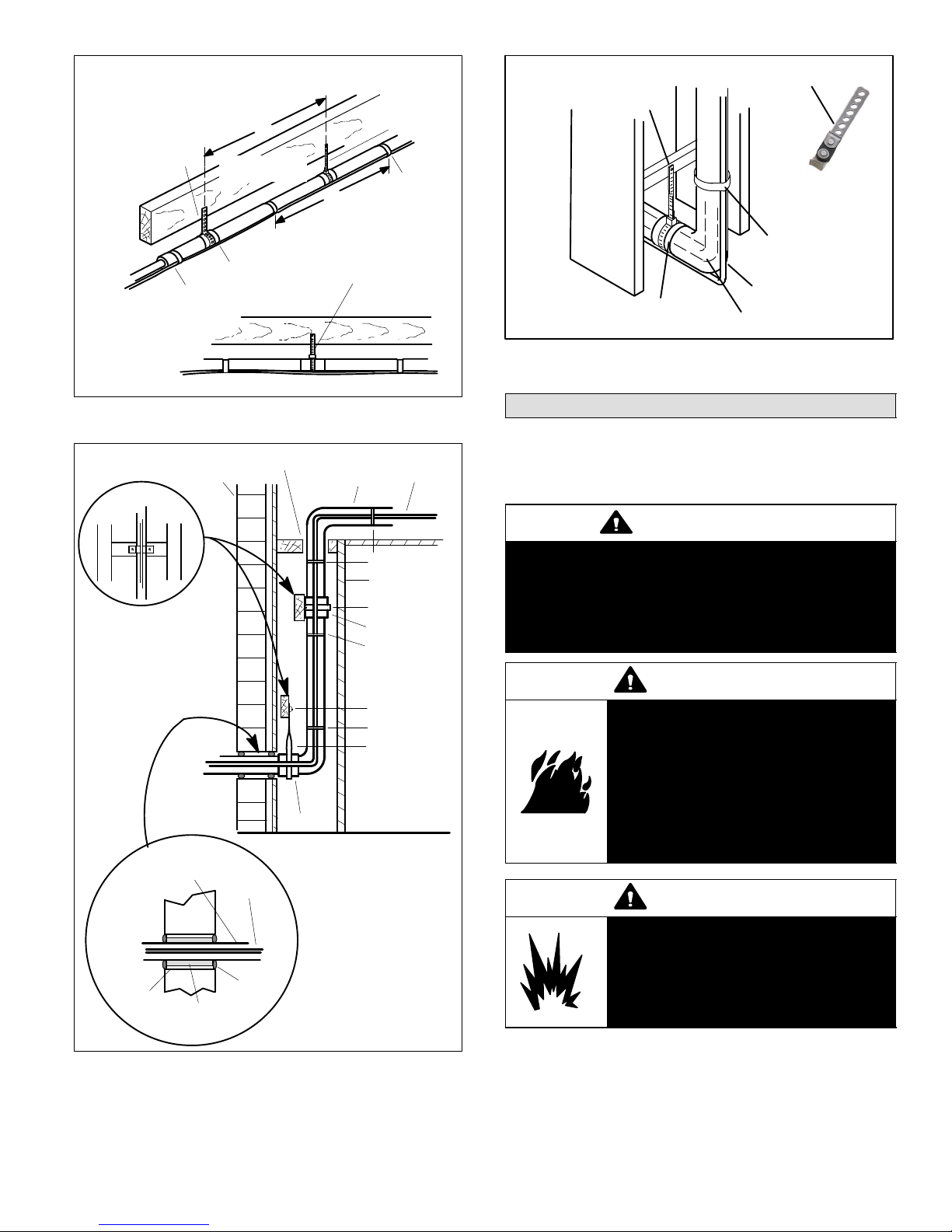
TO HANG LINE SET FROM JOIST OR
RAFTER, USE EITHER METAL STRAPPING
MATERIAL OR ANCHORED HEAVY NYLON
WIRE TIES.
STRAPPING MATERIAL
(AROUND SUCTION
LINE ONLY)
FLOOR JOIST OR
ROOF RAFTER
TAPE OR
WIRE TIE
8 FEET
FLOOR JOIST OR
ROOF RAFTER
METAL
SLEEVE
WIRE TIE
(AROUND
SUCTION LINE
ONLY)
TAPE OR
8 FEET
STRAP THE SUCTION LINE TO
THE JOIST OR RAFTER AT 8 FEET
INTERVALS THEN STRAP THE
LIQUID LINE TO THE SUCTION
LINE.
WIRE TIE
AUTOMOTIVE
STRAP LIQUID LINE
TO SUCTION LINE
LIQUID LINE
SUCTION LINE − WRAPPED
IN ARMAFLEX
ANCHORED HEAVY NYLON
WIRE TIE OR AUTOMOTIVE
MUFFLER-TYPE HANGER
WALL
STUD
METAL SLEEVE
MUFFLER-TYPE HANGER
Figure 18. Refrigerant Line Set: Transition from
Vertical to Horizontal
Figure 16. Refrigerant Line Set: Installing
Horizontal Runs
IMPORTANT - REFRIGERANT LINES
OUTSIDE WALL
WOOD BLOCK
BETWEEN STUDS
NOTE − SIMILAR INSTALLATION
PRACTICES SHOULD BE USED
IF LINE SET IS TO BE INSTALLED
ON EXTERIOR OF OUTSIDE
WALL.
SUCTION LINE
WRAPPED WITH
ARMAFLEX
OUTSIDE
PVC
PIPE
MUST NOT CONTACT WALL.
LIQUID LINE
WALL
CAULK
FIBERGLASS
INSULATION
SUCTION LINE
SLEEVE
IMPORTANT! REFRIGERANT
LINES MUST NOT CONTACT
STRUCTURE.
LIQUID LINE
WIRE TIE
INSIDE WALL
STRAP
SLEEVE
WIRE TIE
WOOD BLOCK
WIRE TIE
STRAP
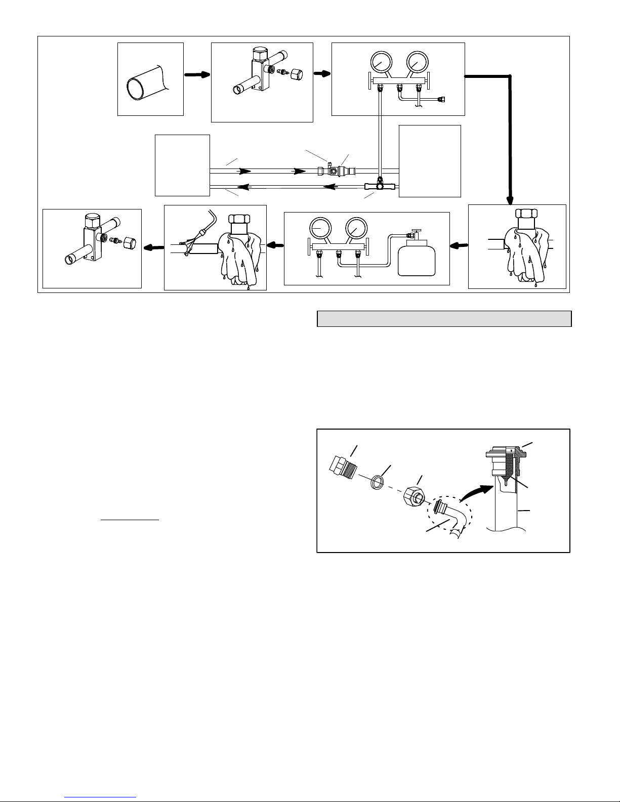
Brazing Connections10
Use the following procedure to braze the line set to the new
air conditioner unit. Figure 19 is provided as a general
guide for preparing to braze the line set to the air
conditioner unit.
WARNING
Polyol ester (POE) oils used with HFC−410A
refrigerant absorb moisture very quickly. It is very
important that the refrigerant system be kept
closed as much as possible. DO NOT remove line
set caps or service valve stub caps until you are
ready to make connections.
WARNING
Danger of fire. Bleeding the
refrigerant charge from only the high
side may result in the low side shell
and suction tubing being
pressurized. Application of a brazing
torch while pressurized may result in
ignition of the refrigerant and oil
mixture − check the high and low
pressures before unbrazing.
WARNING
When using a high pressure gas such
as dry nitrogen to pressurize a
refrigeration or air conditioning
system, use a regulator that can
control the pressure down to 1 or 2
psig (6.9 to 13.8 kPa).
Figure 17. Refrigerant Line Set: Installing Vertical
Runs (New Construction Shown)
1. Cut ends of the refrigerant lines square (free from
nicks or dents). Debur the ends. The pipe must remain
round, do not pinch end of the line.
Page 9
XP19 SERIES
Page 10
1
2
3
CUT AND DEBUR
7
INSTALL CORE ONLY FOR
BOTH SERVICE PORTS after they
have coolED.
INDOOR UNIT
6
BRAZE LINE SET
REMOVE CAP AND CORE FROM
BOTH LIQUID AND SUCTION
SERVICE PORTS
SERVICE PORT MUST BE
OPEN TO ALLOW EXIT
POINT FOR NITROGEN
SUCTION LINE
LIQUID LINE
Figure 19. Brazing Connections
2. Remove service cap and core from both the suction
and liquid line service ports.
3. Connect gauge low pressure side to liquid line service
valve.
4. To protect components during brazing, wrap a wet
cloth around the liquid line service valve body and
copper tube stub and use another wet cloth
underneath the valve body to protect the base paint.
Also, shield the light maroon R−410A sticker.
5. Flow regulated nitrogen (at 1 to 2 psig) through the
refrigeration gauge set into the valve stem port
connection on the liquid line service valve and out of
the valve stem port connection on the suction service
valve.
ATTACH
GAUGES
SERVICE
5
VALVE
SERVICE
VALVE
outdoor
UNIT
FLOW NITROGEN
NITROGEN
4
WRAP
SERVICE
VALV E
Removing Indoor Unit Metering Device11
Remove the existing HCFC−22 refrigerant flow control
orifice or thermal expansion valve from the indoor coil. The
existing indoor unit HCFC−22 metering device is not
approved for use with HFC−410A refrigerant and may
prevent proper flushing.
REPLACEMENT PARTS
If replacement parts are necessary for the indoor unit,
order kit 69J46. The kit includes:
LIQUID LINE ORIFICE HOUSINGS (10)
TEFLON RINGS (20)
BRASS NUTS (10)
PISTON
RETAINER
STRAINER
NOTE The RFCIV or TXV metering device at the indoor
unit will allow low pressure nitrogen to flow through the
system.)
6. Braze the liquid line to the liquid line service valve.
Turn off nitrogen flow. Repeat procedure starting at
paragraph 4 for brazing the suction line to the suction
service valve.
7. After all connections have been brazed, disconnect
manifold gauge set the from service ports, cool down
piping with wet rag and remove all wrappings. Do not
reinstall cores until after evacuation procedures.
Reinstall service caps if desired to close off refrigerant
ports.
505331M 06/09
Page 10
COPPER
TUBE
LIQUID LINE ASSEMBLIES
(INCLUDES STRAINER) (10)
LIQUID LINE
ASSEMBLY
Figure 20. 69J46 Kit Components
TYPICAL FIXED ORIFICE REMOVAL PROCEDURE
1. On fully cased coils, remove the coil access and
plumbing panels.
2. Remove any shipping clamps holding the liquid line
and distributor assembly.
3. Using two wrenches, disconnect liquid line from liquid
line orifice housing. Take care not to twist or damage
distributor tubes during this process.
Page 11

4. Remove and discard fixed orifice, valve stem
assembly if present and Teflon washer as illustrated in
Figure 21.
5. Use a field−provided fitting to temporary reconnect the
liquid line to the indoor unit’s liquid line orifice housing.
DISTRIBUTOR TUBES
LIQUID LINE ORIFICE HOUSING
TEFLON RING
(Uncased Coil Shown)
FIXED
ORIFICE
BRASS NUT
7. Remove and discard TXV and the two Teflon rings.
8. Use a field−provided fitting to temporary reconnect the
liquid line to the indoor unit’s liquid line orifice housing.
Flushing the System12
IMPORTANT
The line set and indoor unit coil must be flushed
with at least the same amount of clean refrigerant
that previously charged the system. Check the
charge in the flushing cylinder before proceeding.
DISTRIBUTOR
ASSEMBLY
REMOVE AND
DISCARD
WHITE TEFLON SEAL
(IF PRESENT)
LIQUID LINE ASSEMBLY
(INCLUDES STRAINER)
Figure 21. Typical Fixed Orifice Removal
TYPICAL TXV REMOVAL PROCEDURE
(Uncased Coil Shown)
TWO PIECE
PATCH PLATE
(UNCASED COIL
ONLY)
DISTRIBUTOR
TUBES
DISTRIBUTOR
ASSEMBLY
MALE EQUALIZER LINE
FITTING
LIQUID LINE
ORIFICE HOUSING
EQUALIZER
LINE
SENSING BULB
STUB END
TXV
TEFLON
RING
LIQUID LINE ASSEMBLY
WITH BRASS NUT
SUCTION
LINE
TEFLON
RING
SENSING
LINE
LIQUID
LINE
Figure 22. Typical TXV Removal
1. On fully cased coils, remove the coil access and
plumbing panels.
2. Remove any shipping clamps holding the liquid line
and distributor assembly.
3. Disconnect the equalizer line from the TXV equalizer
line fitting on the suction line.
4. Remove the suction line sensing bulb.
5. Disconnect the liquid line from the TXV at the liquid line
assembly.
6. Disconnect the TXV from the liquid line orifice housing.
Take care not to twist or damage distributor tubes
during this process.
IMPORTANT
If this unit is being matched with an approved line
set or indoor unit coil which was previously
charged with mineral oil, or if it is being matched
with a coil which was manufactured before
January of 1999, the coil and line set must be
flushed prior to installation. Take care to empty all
existing traps. Polyol ester (POE) oils are used in
Lennox units charged with HFC−410A refrigerant.
Residual mineral oil can act as an insulator,
preventing proper heat transfer. It can also clog
the expansion device, and reduce the system
performance and capacity.
Failure to properly flush the system per the
instructions below will void the warranty.
IMPORTANT
The Environmental Protection Agency (EPA)
prohibits the intentional venting of HFC refrigerants
during maintenance, service, repair and disposal of
appliance. Approved methods of recovery,
recycling or reclaiming must be followed.
INVERTED HCFC−22 CYLINDER
CONTAINS CLEAN HCFC−22 TO
BE USED FOR FLUSHING.
SUCTION LINE
SERVICE VALVE
EXISTING
INDOOR
UNIT
LIQUID LINE SERVICE VALVE
RECOVERY
CYLINDER
SUCTION
LIQUID
NOTE − THE INVERTED HCFC−22 CYLINDER MUST CONTAIN AT LEAST THE SAME
AMOUNT OF REFRIGERANT AS WAS RECOVERED FROM THE EXISTING SYSTEM.
NEW
OUTDOOR
UNIT
OPENED
RECOVERY MACHINE
Figure 23. Typical Flushing Connection
GAUGE
MANIFOLD
LOW
PRESSURE
TANK
RETURN
INLET
DISCHARGE
HIGH
PRESSURE
CLOSED
Page 11
XP19 SERIES
Page 12

CAUTION
This procedure should not be performed on
systems which contain contaminants (Example:
compressor burn out).
If the original system used:
S HCFC−22 refrigerant, then flush the system using the
procedure provided in this section.
9
10
8
11
1/8 TURN
10
8
11
12
7
6
12
1
2
3
9
4
7
5
6
1/2 TURN
1
2
3
4
5
S HFC−410A refrigerant, then proceed to Installing New
Refrigerant Metering Device.
REQUIRED EQUIPMENT
Equipment required to flush the existing line set and indoor
unit coil:
S Two clean HCFC−22 recovery bottles,
S Oilless recovery machine with pump-down feature,
S Two gauge sets (one for HCFC−22; one for
HFC−410A).
FLUSHING PROCEDURE
1. Connect the following:
S HCFC−22 cylinder with clean refrigerant to the
suction service valve,
S HCFC−22 gauge set to the liquid line valve,
S Recovery machine with an empty recovery tank to
the gauge set.
2. Set the recovery machine for liquid recovery and start
the recovery machine. Open the gauge set valves to
allow the recovery machine to pull a vacuum on the
existing system line set and indoor unit coil.
Figure 24. Tightening Distance
TYPICAL CTXV INSTALLATION PROCEDURE
The CTXV unit can be installed internal or external to the
indoor coil. In applications where an uncased coil is being
installed in a field−provided plenum, install the CTXV in a
manner that will provide access for field servicing of the
CTXV. Refer to Figure 25 for reference during installation
of CTXV unit.
TWO PIECE
PATCH PLATE
(UNCASED COIL
ONLY)
DISTRIBUTOR
TUBES
DISTRIBUTOR
ASSEMBLY
(Uncased Coil Shown)
LIQUID LINE
ORIFICE
HOUSING
EQUALIZER
LINE
STUB END
TEFLON
RING
LIQUID LINE ASSEMBLY
WITH BRASS NUT
CTXV
TEFLON
RING
SENSING
LINE
3. Invert the cylinder of clean HCFC−22 and open its
valve to allow liquid refrigerant to flow into the system
through the suction line valve. Allow the refrigerant to
pass from the cylinder and through the line set and the
indoor unit coil before it enters the recovery machine.
4. After all of the liquid refrigerant has been recovered,
switch the recovery machine to suction recovery so
that all of the HCFC−22 suction is recovered. Allow the
recovery machine to pull a vacuum on the system.
5. Close the valve on the inverted HCFC−22 drum and
the gauge set valves. Pump the remaining refrigerant
out of the recovery machine and turn the machine off.
Installing New Indoor Metering Device13
XP19 units use CTXV for metering refrigerant only. This
section provides instructions on installing CTXV
refrigerant metering device.
505331M 06/09
Page 12
MALE EQUALIZER LINE
FITTING (SEE FIGURE 27
FOR FURTHER DETAILS)
SENSING BULB INSULATION IS
REQUIRED IF MOUNTED EXTERNAL
TO THE COIL CASING. SEE FIGURE 26
FOR BULB POSITIONING.
SUCTION
LINE
LIQUID
LINE
Figure 25. Typical TXV Installation
1. Remove the field−provided fitting that temporary
reconnected the liquid line to the indoor unit’s
distributor assembly.
2. Install one of the provided Teflon rings around the
stubbed end of the CTXV and lightly lubricate the
connector threads and expose surface of the Teflon
ring with refrigerant oil.
3. Attach the stubbed end of the CTXV to the liquid line
orifice housing. Finger tighten and use an appropriately
Page 13

sized wrench to turn an additional 1/2 turn clockwise
as illustrated in Figure 24, or 20 ft−lb.
4. Place the remaining Teflon washer around the other
end of the CTXV. Lightly lubricate connector threads
and expose surface of the Teflon ring with refrigerant
oil.
5. Attach the liquid line assembly to the CTXV. Finger
tighten and use an appropriately sized wrench to turn
an additional 1/2 turn clockwise as illustrated in Figure
24, or 20 ft−lb.
6. Attach the suction line sensing bulb in the proper
orientation as illustrated in Figure 26 using the clamp
and screws provided.
NOTE Insulating the sensing bulb once installed may be
required when the bulb location is external to the coil
casing.
SUCTION LINE
BULB
12
ON LINES SMALLER THAN
7/8", MOUNT SENSING BULB
AT EITHER THE 3 OR 9
O’CLOCK POSITION.
BULB
IMPORTANT
When removing the flare nut, ensure that the copper
flare seal bonnet is removed.
8. Connect the equalizer line from the TXV to the
equalizer suction port on the suction line. Finger
tighten the flare nut plus 1/8 turn (7 ft−lbs) as illustrated
in Figure 24.
NOTE To prevent any possibility of water damage,
properly insulate all parts of the TXV assembly that may
sweat due to temperature differences between the valve
and its surrounding ambient temperatures.
See the XP19 Engineering Handbook for approved CTXV
kit match−ups and application information.
The reference CTXV kits include:
1 CTXV
2 Teflon rings
1 1 1/4" wide copper mounting strap for sensing bulb
2 #10 hex head bolts and nuts for securing sensing bulb
SUCTION LINE
12
BULB
NOTE − NEVER MOUNT ON BOTTOM OF LINE.
ON 7/8" AND LARGER LINES,
MOUNT SENSING BULB AT
EITHER THE 4 OR 8 O’CLOCK
POSITION. NEVER MOUNT
ON BOTTOM OF LINE.
BULB
Figure 26. TXV Sensing Bulb Installation
7. Remove and discard either the flare seal cap or flare
nut with copper flare seal bonnet from the equalizer
line port on the suction line as illustrated in Figure 27.
FLARE SEAL
CAP
OR
MALE BRASS EQUALIZER
FLARE NUT
COPPER
FLARE SEAL
BONNET
LINE FITTING
SUCTION LINE
Figure 27. Copper Flare Seal Bonnet Removal
CTXV (1)
HEX HEAD BOLTS
AND NUTS (2)
TEFLON
RINGS (2)
COPPER
MOUNTING
STRAP (1)
Figure 28. CTXV Kit Components
Testing for Leaks14
After the line set has been connected to the indoor unit and
air conditioner, check the line set connections and indoor
unit for leaks. Use the following procedure to test for leaks:
IMPORTANT
Leak detector must be capable of sensing HFC
refrigerant.
WARNING
Refrigerant can be harmful if it is inhaled.
Refrigerant must be used and recovered
responsibly.
Failure to follow this warning may result in personal
injury or death.
Page 13
XP19 SERIES
Page 14

WARNING
When using a high pressure gas such
as dry nitrogen to pressurize a
refrigeration or air conditioning
system, use a regulator that can
control the pressure down to 1 or 2
psig (6.9 to 13.8 kPa).
Evacuating the System15
Evacuating the system of non−condensables is critical for
proper operation of the unit. Non−condensables are
defined as any gas that will not condense under
temperatures and pressures present during operation of
an air conditioning system. Non−condensables and water
suction combine with refrigerant to produce substances
that corrode copper piping and compressor parts.
WARNING
Fire, Explosion and Personal Safety
Hazard.
Failure to follow this warning could
result in damage, personal injury or
death.
Never use oxygen to pressurize or
purge refrigeration lines. Oxygen,
when exposed to a spark or open
flame, can cause damage by fire and/
or an explosion, that could result in
personal injury or death.
1. Connect an HFC−410A manifold gauge set high
pressure hose to the suction valve service port.
(Normally, the high pressure hose is connected to the
liquid line port; however, connecting it to the suction
port better protects the manifold gauge set from high
pressure damage.)
2. With both manifold valves closed, connect the cylinder
of HFC−410A refrigerant to the center port of the
manifold gauge set. Open the valve on the HFC−410A
cylinder (suction only).
3. Open the high pressure side of the manifold to allow
HFC−410A into the line set and indoor unit. Weigh in
a trace amount of HFC−410A. [A trace amount is a
maximum of two ounces (57 g) refrigerant or three
pounds (31 kPa) pressure]. Close the valve on the
HFC−410A cylinder and the valve on the high pressure
side of the manifold gauge set. Disconnect the
HFC−410A cylinder.
4. Connect a cylinder of dry nitrogen with a pressure
regulating valve to the center port of the manifold
gauge set.
5. Adjust dry nitrogen pressure to 150 psig (1034 kPa).
Open the valve on the high side of the manifold gauge
set in order to pressurize the line set and the indoor unit.
6. After a few minutes, open one of the service valve
ports and verify that the refrigerant added to the
system earlier is measurable with a leak detector.
7. After leak testing disconnect gauges from service
ports.
WARNING
Danger of Equipment Damage. Avoid deep
vacuum operation. Do not use compressors to
evacuate a system. Extremely low vacuums can
cause internal arcing and compressor failure.
Damage caused by deep vacuum operation will
void warranty.
IMPORTANT
Use a thermocouple or thermistor electronic
vacuum gauge that is calibrated in microns. Use an
instrument capable of accurately measuring down
to 50 microns.
NOTE Remove cores from service valves if not already
done.
1. Connect manifold gauge set to the service valve ports
as follows:
S low pressure gauge to suction line service valve
S high pressure gauge to liquid line service valve
2. Connect micron gauge.
3. Connect the vacuum pump (with vacuum gauge) to
the center port of the manifold gauge set.
4. Open both manifold valves and start the vacuum
pump.
5. Evacuate the line set and indoor unit to an absolute
pressure of 23,000 microns (29.01 inches of
mercury).
NOTE During the early stages of evacuation, it is
desirable to close the manifold gauge valve at least once to
determine if there is a rapid rise in sure indicates a
relatively large leak. If this occurs, repeat the leak testing
procedure.
NOTE The term absolute pressure means the total
actual pressure within a given volume or system, above
the absolute zero of pressure. Absolute pressure in a
vacuum is equal to atmospheric pressure minus vacuum
pressure.
6. When the absolute pressure reaches 23,000 microns
(29.01 inches of mercury), close the manifold gauge
valves, turn off the vacuum pump and disconnect the
manifold gauge center port hose from vacuum pump.
Attach the manifold center port hose to a dry nitrogen
505331M 06/09
Page 14
Page 15

cylinder with pressure regulator set to 150 psig (1034
kPa) and purge the hose. Open the manifold gauge
valves to break the vacuum in the line set and indoor
unit. Close the manifold gauge valves.
7. Shut off the dry nitrogen cylinder and remove the
manifold gauge hose from the cylinder. Open the
manifold gauge valves to release the dry nitrogen from
the line set and indoor unit.
8. Reconnect the manifold gauge to the vacuum pump,
turn the pump on, and continue to evacuate the line set
and indoor unit until the absolute pressure does not
rise above 500 microns (29.9 inches of mercury) within
a 20−minute period after shutting off the vacuum pump
and closing the manifold gauge valves.
9. When the absolute pressure requirement above has
been met, disconnect the manifold hose from the
vacuum pump and connect it to an upright cylinder of
HFC−410A refrigerant. Open the manifold gauge valve
1 to 2 psig in order to release the vacuum in the line set
and indoor unit.
10. Perform the following:
A Close manifold gauge valves.
B Shut off HFC−410A cylinder.
C Reinstall service valve cores by removing
manifold hose form service valve. Quickly install
core with core tool while maintaining a positive
system pressure.
D Replace the stem caps and secure finger tight,
then tighten an additional one−sixth (1/6) of a turn
as illustrated in Figure 2.
Servicing Units Delivered Void of
Charge16
If the outdoor unit is void of refrigerant, clean the system
using the procedure described below.
1. Use nitrogen to pressurize the system and check for
leaks. Repair all leaks.
2. Evacuate the system to remove as much of the
moisture as possible.
3. Use nitrogen to break the vacuum and install a new
filter drier in the system.
4. Evacuate the system again. Then, weigh the
appropriate amount of HFC−410A refrigerant as listed
on unit nameplate into the system.
5. Monitor the system to determine the amount of
moisture remaining in the oil. It may be necessary to
replace the filter drier several times to achieve the
required dryness level. If system dryness is not
verified, the compressor will fail in the future.
Figure 29. XP19 Wiring
Page 15
BLUE WIRE
Y2 OUT
DEFROST
BOARD
DETAIL
SHIPPED AS SHOWN ABOVE WITH TERMINAL CRIMPED TO BLUE
WIRE; USE TERMINAL OR CUT OFF TERMINAL AND SPLICE BLUE
WIRE WITH Y2 WIRE TO INDOOR UNIT.
WITH CRIMPED
TERMINAL
XP19 SERIES
Page 16

Electrical Connections17
WARNING
Electric shock hazard. Can cause
injury or death.
Line voltage is present at all
components on units with single−pole
contactors, even when unit is not in
operation!
Unit may have multiple power
supplies. Disconnect all remote
electric power supplies before
opening access panel.
Unit must be grounded in accordance
with national and local codes.
In the U.S.A., wiring must conform with current local codes
and the current National Electric Code (NEC). In Canada,
wiring must conform with current local codes and the current
Canadian Electrical Code (CEC).
Refer to the furnace or blower coil installation instructions
for additional wiring application diagrams and refer to unit
nameplate for minimum circuit ampacity and maximum
overcurrent protection size.
230VAC SUPPLY VOLTAGE
The XP19 outdoor unit is rated for 230VAC applications
only. A hard-start kit is required for applications where the
supply voltage is less than 230VAC.
24VAC TRANSFORMER
Use the transformer provided with the furnace or coil
blower for low-voltage control power (24VAC − 40 VA
minimum)
NOTE The addition of accessories to the system could
exceed the 40 VA power requirement of the
factory-provided transformer. Measure the system’s
current and voltage after installation is complete to
determine transformer loading. If loading exceeds the
factory-provided transformer capacity, a larger
field-provided transformer will need to be installed in the
system.
WIRING CONNECTIONS
1. Install line voltage power supply to unit from a properly
sized disconnect switch.
2. Ground unit at unit disconnect switch or to an earth
ground.
NOTE Connect conduit to the unit using a proper
conduit fitting. Units are approved for use only with
copper conductors. A complete unit wiring diagram is
located on the back side of the unit’s access panel.
NOTE For proper voltages, select thermostat wire
gauge per the following chart:
Table 3. Wire Run Length
Wire Run Length AWG # Insulation Type
less than 100’ (30m) 18
more than 100’ (30m) 16
3. Install room thermostat (ordered separately) on an
inside wall approximately in the center of the area and
5 feet (1.5 m) from the floor. Do not install on an outside
wall or where sunlight, drafts or vibrations affect it.
4. Install low voltage wiring from outdoor to indoor unit
and from thermostat to indoor unit as illustrated in
Figure 29.
THERMOSTAT SECOND−STAGE COOLING
CONNECTIONS
The Lennox System Operation Monitor (LSOM) requires a
twos−stage room thermostat to operating properly.
color−coded, temperature
rating 35ºC minimum
S Y2 Room Thermostat Wire Connect the Y2 room
thermostat wire from the outdoor unit to the Y2 input
on the DCB.
S L Terminal Wiring Connect L terminal of the room
thermostat to the L (brown) field wire connection.
S Y2 DC Solenoid Connector (DC SOL) The two−pin
DC solenoid connector is connected at the factory to
the compressor second−state solenoid connector. No
field connections are required for this component.
NOTE Wiring the module incorrectly will cause false
LED codes. Table 14 describes LED operation when the
module is incorrectly wired and the action required to
correct the problem.
Start−Up and Charging Procedures18
IMPORTANT
If unit is equipped with a crankcase heater, it should
be energized 24 hours before unit start−up to
prevent compressor damage as a result of slugging.
1. Rotate fan to check for binding.
2. Inspect all factory− and field−installed wiring for loose
connections.
3. After evacuation is complete, open both the liquid and
vapor line service valves to release the refrigerant
charge contained in outdoor unit into the system.
4. Replace the stem caps and tighten to the value listed
in Table 1.
5. Check voltage supply at the disconnect switch. The
voltage must be within the range listed on the unit’s
nameplate. If not, do not start the equipment until you
have consulted with the power company and the
voltage condition has been corrected.
6. Set the thermostat for a cooling demand. Turn on
power to the indoor indoor unit and close the outdoor
unit disconnect switch to start the unit.
7. Recheck voltage while the unit is running. Power must
be within range shown on the nameplate.
505331M 06/09
Page 16
Page 17

8. Check system for sufficient refrigerate by using the
procedures listed under Testing and Charging
System.
TESTING AND CHARGING SYSTEM
This system uses HFC−410A refrigerant which operates at
much higher pressures than HCFC−22. The pre−installed
liquid line filter drier is approved for use with HFC−410A
only. Do not replace it with components designed for use
with HCFC−22. This unit is NOT approved for use with coils
which use capillary tubes as a refrigerant metering device.
SETTING UP TO CHECK CHARGE
1. Close manifold gauge set valves. Connect the center
manifold hose to an upright cylinder of HFC−410A.
2. Connect the manifold gauge set to the unit’s service
ports as illustrated in Figure 3.
D low pressure gauge to vapor service port
D high pressure gauge to liquid service port
COOLING MODE INDOOR AIRFLOW CHECK
Check airflow using the Delta−T (
DT) process using the
illustration in Figure 30.
HEATING MODE INDOOR AIRFLOW CHECK
Blower airflow (CFM) may be calculated by energizing
electric heat and measuring:
Temp.
of air
entering
indoor
coil ºF
A
Wet−bulb ºF
53º
DRY
BULB
80 24 24 24 23 23 22 22 22 20 19 18 17 16 15
78 23 23 23 22 22 21 21 20 19 18 17 16 15 14
76 22 22 22 21 21 20 19 19 18 17 16 15 14 13
74 21 21 21 20 19 19 18 17 16 16 15 14 13 12
Dry−bulb
72 20 20 19 18 17 17 16 15 15 14 13 12 11 10
70 19 19 18 18 17 17 16 15 15 14 13 12 11 10
57 58 59 60 61 62 63 64 65 66 67 68 69 70
T
C
Drop
19º
All temperatures are
expressed in ºF
DT
air flowair flow
INDOOR
COIL
B
A
72º
B
64º
WET
BULB
DRY
BULB
S Temperature rise between the return air and supply air
temperatures at the indoor coil blower unit,
S Measuring voltage supplied to the unit,
S Measuring amperage being drawn by the heat unit(s).
Then, apply the measurements taken in following formula
to determine CFM:
CFM =
CALCULATING CHARGE
If the system is void of refrigerant, first, locate and repair
any leaks and then weigh in the refrigerant charge into the
unit. To calculate the total refrigerant charge:
Amount
specified
on
nameplate
1. Determine the desired DTMeasure entering air temperature
using dry bulb (A) and wet bulb (B). DT is the intersecting value of A
and B in the Table (see triangle).
2. Find temperature drop across coilMeasure the coil’s dry bulb
entering and leaving air temperatures (A and C). Temperature Drop
Formula: (T
3. Determine if fan needs adjustmentIf the difference between the
measured T
justment is needed. See examples: Assume DT = 15 and A temp. =
72º, these C temperatures would necessitate stated actions:
Cº T
Drop
53º 19 – 15 = 4 Increase the airflow
58º 14 – 15 = −1 (within +3º range) no change
62º 10 – 15 = −5 Decrease the airflow
4. Adjust the fan speedSee indoor unit instructions to in-
crease/decrease fan speed.
Changing air flow affects all temperatures; recheck temperatures to
confirm that the temperature drop and DT are within +3º.
Amps x Volts x 3.41
1.08 x Temperature rise (F)
Additional charge
Adjust amount. for
variation in line set
length listed on Table
in Figure 31.
specified per
indoor unit
match−up listed in
Tables 4 through
+ + =
) = A minus C.
Drop
and the desired DT (T
Drop
– DT = ºF ACTION
–DT) is within +3º, no ad-
Drop
7.
charge
Total
Figure 30. Checking Indoor Airflow over Evaporator Coil using Delta−T Chart
Page 17
XP19 SERIES
Page 18

WEIGH IN
Refrigerant Charge per Line Set Length
Liquid Line
Set Diameter
3/8" (9.5 mm)
NOTE − *If line length is greater than 15 ft. (4.6 m), add this
amount. If line length is less than 15 ft. (4.6 m), subtract this
amount.
SUBCOOLING
Ounces per 5 feet (g per 1.5 m)
adjust from 15 feet (4.6 m) line set*
3 ounce per 5’ (85 g per 1.5 m)
1 Check the airflow as illustrated in Figure 30 to be sure the indoor airflow is as required.
(Make any air flow adjustments before continuing with the following procedure.)
2 Measure outdoor ambient temperature; determine whether to use cooling mode or
heating mode to check charge.
3 Connect gauge set.
4 Check liquid and vapor line pressures. Compare pressures with either cooling or heating
mode normal operating pressures in Table 8 (second stage − high capacity).
USE COOLING
MODE
60ºF (15º)
USE HEATING
MODE
NOTE − The reference table is a general guide. Expect minor pressure variations. Significant
differences may mean improper charge or other system problem.)
5 Set thermostat for heat/cool demand, depending on mode being used:
Using cooling modeWhen the outdoor ambient temperature is 60°F (15°C) and above.
Target subcooling values (second stage − high capacity) in Table 8 are based on 70 to 80°F
(21−27°C) indoor return air temperature; if necessary, operate heating to reach that
temperature range; then set thermostat to cooling mode setpoint to 68ºF (20ºC) which should
call for second stage (high capacity) cooling. When pressures have stabilized, continue with
step 6.
Figure 31. Using Weigh In Method
1. Check Liquid and suction line pressures
2. Compare unit pressures with Table 8,
Normal Operating Pressures.
3. Conduct leak check; evacuate as
previously outlined.
4. Weigh in the unit nameplate charge plus
any charge required for line set differences
over feet.
This nameplate is for illustration purposes
only. Go to actual nameplate on outdoor
unit for charge information.
SATº
LIQº –
SCº =
Using heating modeWhen the outdoor ambient temperature is below 60°F (15°C). Target
subcooling values (second stage − high capacity) in Table 8 are based on 65−75°F (18−24°C)
indoor return air temperature; if necessary, operate cooling to reach that temperature range;
then set thermostat to heating mode setpoint to 77ºF (25ºC) which should call for second stage
(high capacity) heating. When pressures have stabilized, continue with step 6.
6 Read the liquid line temperature; record in the LIQº space.
7 Read the liquid line pressure; then find its corresponding temperature in the temperature/
pressure chart listed in Table 9 and record it in the SATº space.
8 Subtract LIQº temp. from SATº temp. to determine subcooling; record it in SCº space.
9 Compare SCº results with tables below, being sure to note any additional charge for line set
and/or match−up.
10 If subcooling value is greater than shown in Tables 4 through 7 for the applicable unit, remove
refrigerant; if less than shown, add refrigerant.
11 If refrigerant is added or removed, repeat steps 4 through 10 to verify charge.
Figure 32. Using Subcooling Method Second Stage (High Capacity)
505331M 06/09
Page 18
Page 19

** Amount of charge required in additional to charge shown
on unit nameplate. Remember to consider line set length
difference.
Table 4 XP19−024
INDOOR HEAT
MATCH−UP PUMP
C33−31 12 7 0 1
C33–38 SN# before SN#6007K 31 7 0 6
C33–38 SN#6007K and after 10 8 0 6
CBX27UH−030−230 10 6 0 6
CB30U−31 12 7 0 1
CB30U−41 10 6 0 6
CB31MV−41 10 6 0 6
CBX32M−030−230 12 7 0 1
CBX32M−036−230 10 6 0 6
CBX32MV−024/030−230 12 8 0 0
CBX32MV−036−230 10 6 0 6
CBX40UHV−024, −030 12 8 0 0
CBX40UHV−036 10 6 0 6
CH33−44/48, −48C 8 7 1 0
CR33−48 6 6 1 3
CR33−50/60 8 6 1 0
CR33−60 8 6 1 0
CX34−31 12 7 0 1
CX34−38 SN# before SN#6007K 31 7 0 6
CX34−38 SN#6007K and after 10 8 0 6
TargetSubcooling
HeatingCooling
5ºF)(+1ºF)
(+
**Add
charge
lb oz
Table 5 XP19−036
INDOOR HEAT
MATCH−UP PUMP
C33−38 SN# before SN#6007K 31 7 0 0
C33−38 SN#6007K and after 10 8 0 0
C33−44, −48 14 6 0 7
C33−49 6 6 1 5
C33−50/60C 12 5 0 13
C33−60D 8 5 0 15
C33−62D 6 6 1 5
CH23−51 14 6 0 5
CH23−65 12 5 0 13
CBX27UH−036−230 14 6 0 7
CBX27UH−042−230 6 6 1 5
CB29M−51 6 6 1 5
CB30M−41, −46 14 6 0 7
CB30M−51 6 6 1 5
CB30U−51 6 6 1 5
CB31MV−41 14 6 0 7
CB31MV−51 6 6 1 5
CBX32M−036−230 14 6 0 7
CBX32M−042−230 14 6 0 7
CBX32M−048−230 6 6 1 5
CBX32MV−036−230 14 6 0 5
CBX32MV−048−230 6 6 1 5
CBX40UHV−036 14 6 0 5
CBX40UHV−042, −048 6 6 1 5
CH33−44/48B 12 5 0 13
CH33−48 12 5 0 13
CR33−48 30 5 0 0
CR33−50/60, −60 15 4 1 5
TargetSubcooling
HeatingCooling
5ºF)(+1ºF)
(+
**Add
charge
lb oz
Table 8 XP19−036 (Continued)
INDOOR HEAT
MATCH−UP PUMP
CX34−48 SN# before SN#6007K 31 7 0 0
CX34−48 SN#6007K and after 10 8 0 0
CX34−44/48 30 5 0 0
CX34−49 6 6 1 5
CX34−50/60C 12 5 0 13
CX34−60D 8 5 0 15
CX34−62D 6 6 1 5
TargetSubcooling
HeatingCooling
5ºF)(+1ºF)
(+
**Add
charge
Table 6 XP19−048
INDOOR HEAT
MATCH−UP PUMP
C33−49 13 5 0 5
C33−60D 20 4 0 0
C33−62C, −62D 12 5 0 8
CBX27UH−048−230 13 5 0 5
CBX27UH−060−230 13 5 0 5
CB30M−51, −65 13 5 0 5
CB30U−51, −65 13 5 0 5
CB31MV−51, −65 13 5 0 5
CBX32M−048−230 13 5 0 5
CBX32M−060−230 13 5 0 5
CBX32MV−048−230 13 5 0 5
CBX32MV−060−230 13 6 0 5
CBX32MV−068−230 10 6 0 13
CBX40UHV−048 13 5 0 5
CBX40UHV−060 13 6 0 5
CH23−68 12 7 0 13
CH33−50/60C 20 7 0 5
CH33−62D 13 5 0 5
CR33−50/60. −60 20 4 0 5
CX34−49 13 5 0 5
CX34−60D 20 4 0 0
CX34−62C, −62D 12 5 0 8
TargetSubcooling
HeatingCooling
5ºF)(+1ºF)
(+
**Add
charge
lb oz
Table 7 XP19−060
INDOOR HEAT
MATCH−UP PUMP
C33−49 16 5 1 0
C33−60D 24 5 0 0
C33−62C, −62D 13 5 0 11
CBX27UH−060−230 16 5 1 0
CB30M−51, −65 16 5 1 0
CB30U−41, −65 16 5 1 0
CB31MV−51, −65 16 5 1 0
CBX32M−048−230 16 5 1 0
CBX32M−060−230 16 5 1 0
CBX32MV−048−230 16 5 1 0
CBX32MV−060−230 16 6 1 0
CBX32MV−068−230 14 4 1 0
CBX40UHV−048 16 5 1 0
CBX40UHV−060 16 6 1 0
CH23−68 14 4 1 0
CH33−62D 18 4 1 0
CR33−50/60, −60 24 5 0 0
CX34−49 16 5 1 0
CX34−60D 24 5 0 0
CX34−62C, −62D 13 5 0 11
TargetSubcooling
HeatingCooling
5ºF)(+1ºF)
(+
**Add
charge
lb oz
Page 19
XP19 SERIES
Page 20

Table 8. Normal Operating Pressure − Liquid +10 and Vapor
+
5 PSIG*
IMPORTANT
Minor variations in these pressures may be
expected due to differences in installations.
Significant differences could mean that the system
is not properly charged or that a problem exists with
some component in the system.
XP19−024 XP19−036 XP19−048 XP19−060
5F (5C)**
40 (4.4) 314 100 316 99 350 98 365 96
50 (10) 334 120 334 11 7 367 111 388 112
20 (−7.0) 304 68 294 64 314 60 346 60
30 (−1.0) 323 82 313 77 331 72 362 72
40 (4.4) 342 98 329 89 358 85 382 85
50 (10) 364 11 6 344 109 384 107 409 106
65 (18.3) 226 152 230 148 210 136 234 135
75 (23.9) 262 151 267 150 242 138 274 137
85 (29.4) 304 152 309 153 286 140 314 142
95 (35.0) 351 155 355 155 328 142 361 147
105 (40.6) 400 158 404 157 374 144 413 147
115 (49.0) 454 161 460 159 426 146 470 149
65 (18.3) 228 146 236 144 227 11 4 237 131
75 (23.9) 267 148 275 145 265 123 276 133
85 (29.4) 309 149 318 148 306 132 320 135
95 (35.0) 358 151 365 150 348 138 369 138
105 (40.6) 410 152 416 153 397 141 423 140
115 (49.0) 465 154 473 155 453 143 482 144
Liq Vap Liq Vap Liq Vap Liq Vap
First Stage (Low Capacity)
Second Stage (High Capacity)
First Stage (Low Capacity)
Second Stage (High Capacity)
Table 9
. HFC−410A Temperature (°F) − Pressure (Psig)
°F Psig °F Psig °F Psig °F Psig
32 100.8 63 178.5 94 290.8 125 445.9
33 102.9 64 181.6 95 295.1 126 451.8
34 105.0 65 184.3 96 299.4 127 457.6
35 107.1 66 187.7 97 303.8 128 463.5
36 109.2 67 190.9 98 308.2 129 469.5
37 111.4 68 194.1 99 312.7 130 475.6
38 113.6 69 197.3 100 317.2 131 481.6
39 115.8 70 200.6 101 321.8 132 487.8
40 118.0 71 203.9 102 326.4 133 494.0
41 120.3 72 207.2 103 331.0 134 500.2
42 122.6 73 210.6 104 335.7 135 506.5
43 125.0 74 214.0 105 340.5 136 512.9
44 127.3 75 217.4 106 345.3 137 519.3
45 129.7 76 220.9 107 350.1 138 525.8
46 132.2 77 224.4 108 355.0 139 532.4
47 134.6 78 228.0 109 360.0 140 539.0
48 137.1 79 231.6 110 365.0 141 545.6
49 139.6 80 235.3 111 370.0 142 552.3
50 142.2 81 239.0 112 375.1 143 559.1
51 144.8 82 242.7 113 380.2 144 565.9
52 147.4 83 246.5 114 385.4 145 572.8
53 150.1 84 250.3 115 390.7 146 579.8
54 152.8 85 254.1 116 396.0 147 586.8
55 155.5 86 258.0 117 401.3 148 593.8
56 158.2 87 262.0 118 406.7 149 601.0
57 161.0 88 266.0 119 412.2 150 608.1
58 163.9 89 270.0 120 417.7 151 615.4
59 166.7 90 274.1 121 423.2 152 622.7
60 169.6 91 278.2 122 428.8 153 630.1
61 172.6 92 282.3 123 434.5 154 637.5
62 175.4 93 286.5 124 440.2 155 645.0
INSTALLING SERVICE VALVE CAPS
Disconnect gauge set and re−install all service valve caps.
OUTDOOR UNIT
SERVICE VALVE
INSTALL CAPS
*These are most−popular−match−up pressures. Indoor match up,
indoor air quality, and indoor load cause pressures to vary.
**Temperature of the air entering the outside coil.
505331M 06/09
Figure 33. Installing Service Valve Port Caps
Page 20
Page 21

System Operations19
The outdoor unit and indoor blower cycle on demand from
the room thermostat. When the thermostat blower switch
is in the ON position, the indoor blower operates
continuously.
THERMOSTAT OPERATION
Some indoor thermostats incorporate isolating contacts
and an emergency heat function (which includes an amber
indicating light). The thermostat is not included with the
unit and must be purchased separately.
EMERGENCY HEAT (AMBER LIGHT)
An emergency heat function is designed into some room
thermostats. This feature is applicable when isolation of the
outdoor unit is required, or when auxiliary electric heat is
staged by outdoor thermostats. When the room thermostat is
placed in the emergency heat position, the outdoor unit
control circuit is isolated from power and field-provided relays
bypass the outdoor thermostats. An amber indicating light
simultaneously comes on to remind the homeowner that the
unit is operating in the emergency heat mode.
Emergency heat is usually used during an outdoor unit
shutdown, but it should also be used following a power
outage if power has been off for over an hour and the
outdoor temperature is below 50°F (10°C). The system
should be left in the emergency heat mode at least six
hours to allow the crankcase heater sufficient time to
prevent compressor slugging.
FILTER DRIER
The unit is equipped with a large−capacity biflow filter drier
which keeps the system clean and dry. If replacement is
necessary, order another of like design and capacity.
Lennox System Operation Monitor
(LSOM) (100034−1)20
The diagnostic indicator detects the most common fault
conditions in the air conditioning system. When an
abnormal condition is detected, the module communicates
the specific condition through its ALERT and TRIP lights.
The module is capable of detecting both mechanical and
electrical system problems.
IMPORTANT
This monitor does not provide safety protection.
The is a monitoring device only and cannot control
or shut down other devices.
LSOMLED FUNCTIONS
The LSOM LED functions are described as follows:
Table 10. LED Functions
Label LED
Color
Power Green Indicates voltage within the range of
Alert Yellow Communicates an abnormal system
Trip Red Indicates there is a demand signal
Refer to Table 12 for the complete explanation of
troubleshooting codes.
RESETTING ALERT CODES
Alert codes can be reset manually or automatically:
Manual Reset
Cycle the 24VAC power to LSOM off and on. After power
up, existing code will display for 60 seconds and then clear.
Manual reset can be achieve by any of the following
methods:
S Disconnecting R wire from the LSOM’s R terminal.
S Turning the indoor unit off an on again
Automatic Reset
After an alert is detected, the LSOM continues to monitor
the compressor and system. When/if conditions return to
normal, the alert code is turned off automatically.
Function
19−28VAC is present at the system
monitor power connection.
condition through a unique flash code.
The alert LED flashes a number of
times consecutively; then pauses;
then repeats the process. This
consecutive flashing correlates to a
particular abnormal condition.
from the thermostat but no current to
the compressor is detected by the
module.
Page 21
XP19 SERIES
Page 22

Status LED
Condition
Table 11. LSOM Module LED Troubleshooting Codes
Mis−wired Module
Indication
Status LED Troubleshooting Information
Green LED ON Module not powering up.
Green LED Intermittent
Red LED ON
Module powers up only when
compressor runs.
LED is on but system and
compressor check OK.
Red and Yellow LED Simultaneous flashing.
Table 12. LSOM System LED Troubleshooting Codes
Status LED
Condition
Red LED ON
Yellow Flash Code 1
Yellow Flash Code 2
Yellow Flash Code 3
Status LED Description Status LED Troubleshooting Information
Thermostat demand signal Y1 is
present, but compressor not
running
Long Run Time − Compressor
is running extremely long run
cycles.
System Pressure Trip −
Discharge or suction pressure
out of limits or compressor
overloaded
Short Cycling − Compressor is
running only briefly
Determine/verify that both R and C module terminals are connected and voltage is
present at both terminals.
Determine if R and Y terminals are wired in reverse. Verify module’s R and C
terminals have a constant source.
1
Verify Y terminal is connected to 24VAC at contactor coil.
2
Verify voltage at contactor coil falls below 0.5VAC when off.
3
Verify 24VAC is present across Y and C when thermostat demand signal is
present; if not present, R and C wires are reversed.
Indicates that the control circuit voltage is too low for operation. Verify R and C
terminals are supplied with 19−28VAC.
1
Compressor protector is open.
S Check for high head pressure
S Check compressor supply voltage
2
Outdoor unit power disconnect is open.
3
Compressor circuit breaker or fuse(s) is open.
4
Broken wire or connector is not making contact.
5
Low or high pressure switch open if present in the system.
6
Compressor contactor has failed to close.
1
Low refrigerant charge.
2
Evaporator blower is not running.
S Check blower relay coil and contacts
S Check blower motor capacitor
S Check blower motor for failure or blockage
S Check evaporator blower wiring and connectors
S Check indoor blower control board
S Check thermostat wiring for open circuit
3
Evaporator coil is frozen.
S Check for low suction pressure
S Check for excessively low thermostat setting
S Check evaporator airflow (coil blockages or return air filter)
S Check ductwork or registers for blockage.
4
Faulty metering device.
S Check TXV bulb installation (size, location and contact)
S Check if TXV/fixed orifice is stuck closed or defective
5
Condenser coil is dirty
6
Liquid line restriction (filter drier blocked if present)
7
Thermostat is malfunctioning
.
.
.
S Check thermostat sub−base or wiring for short circuit
S Check thermostat installation (location and level)
1
High head pressure.
S Check high pressure switch if present in system
S Check if system is overcharged with refrigerant
S Check for non−condensable in system
2
Condenser coil poor air circulation (dirty, blocked, damaged).
3
Condenser fan is not running.
S Check fan capacitor
S Check fan wiring and connectors
S Check fan motor for failure or blockage
4
Return air duct has substantial leakage.
1
Thermostat demand signal is intermittent.
2
Time delay relay or control board is defective.
3
If high pressure switch is present, see Flash Code 2 information.
505331M 06/09
Page 22
Page 23

Status LED
Condition
Yellow Flash Code 4 Locked Rotor
Yellow Flash Code 5 Open Circuit
Yellow Flash Code 6
Yellow Flash Code 7
Yellow Flash Code 8
Yellow Flash Code 9
Open Start Circuit − Current
only in run circuit
Open Run Circuit − Current
only in start circuit
Welded Contactor −
Compressor always runs
Low Voltage − Control circuit
<17VAC
Status LED Troubleshooting InformationStatus LED Description
1
Run capacitor has failed.
2
Low line voltage (contact utility if voltage at disconnect is low).
S Check wiring connections
3
Excessive liquid refrigerant in the compressor.
4
Compressor bearings are seized.
1
Outdoor unit power disconnect is open.
2
Unit circuit breaker or fuse(s) is open.
3
Unit contactor has failed to close.
S Check compressor contactor wiring and connectors
S Check for compressor contactor failure (burned, pitted or open)
S Check wiring and connectors between supply and compressor
S Check for low pilot voltage at compressor contactor coil
4
High pressure switch is open and requires manual reset.
5
Open circuit in compressor supply wiring or connections.
6
Unusually long compressor protector reset time due to extreme ambient temperature.
7
Compressor windings are damaged.
S Check compressor motor winding resistance
1
Run capacitor has failed.
2
Open circuit in compressor start wiring or connections.
S Check wiring and connectors between supply and the compressor S terminal
3
Compressor start winding is damaged.
S Check compressor motor winding resistance
1
Open circuit in compressor start wiring or connections.
S Check wiring and connectors between supply and the compressor R terminal
2
Compressor start winding is damaged.
S Check compressor motor winding resistance
1
Compressor contactor failed to open.
2
Thermostat demand signal not connected to module.
1
Control circuit transformer is overloaded.
2
Low line voltage (contact utility if voltage at disconnect is low).
S Check wiring connections
NOTE − Last code will display for 1 minute when power is cycled to module. Power must be on to module for a minimum of 1 minute for code to clear.
NOTE − Upon Y2 signal detection and after 5 seconds, the LSOM module will send 24 VAC to the solenoid. Once the solenoid is fully energized, the LSOM
module reduces voltage to between 4 to 18 VDC . Every 15 minutes the solenoid voltage will be increase to 24 volts for a few seconds to ensure solenoid
valve is engaged until Y2 signal is no longer present.
Page 23
XP19 SERIES
Page 24

Defrost System21
DEFROST SYSTEM DESCRIPTION
The defrost control board (DCB) measures differential
temperatures to detect when the system is performing
poorly because of ice build−up on the outdoor coil. The
controller self−calibrates when the defrost system starts
and after each system defrost cycle. The DCB
components are illustrated on page 22.
The DCB monitors ambient temperature, outdoor coil
temperature, and total run time to determine when a
defrost cycle is required. The coil temperature probe is
designed with a spring clip to allow mounting to the outside
coil tubing. The location of the coil sensor is important for
proper defrost operation.
NOTE The DCB accurately measures the performance
of the system as frost accumulates on the outdoor coil.
This typically will translate into longer running time
between defrost cycles as more frost accumulates on the
outdoor coil before the board initiates defrost cycles.
DIAGNOSTIC LEDS
The state (Off, On, Flashing) of two LEDs on the DCB
(DS1 [Red] and DS2 [Green]) indicate diagnostics
conditions that are described in Table 15.
DCB PRESSURE SWITCH CONNECTIONS
The unit’s automatic reset pressure switches (LO PS − S87
and HI PS − S4) are factory−wired into the DCB on the
LO−PS and HI−PS terminals, respectively.
Low Pressure Switch (LO−PS) When the low pressure
switch trips, the DCB will cycle off the compressor, and the
strike counter in the board will count one strike. The low
pressure switch is ignored under the following conditions:
S during the defrost cycle and 90 seconds after the
termination of defrost
S when the average ambient sensor temperature is
below 15° F (−9°C)
S for 90 seconds following the start up of the compressor
S during TEST mode
High Pressure Switch (HI−PS)When the high pressure
switch trips, the DCB will cycle off the compressor, and the
strike counter in the board will count one strike.
DCB PRESSURE SWITCH EVENT SETTINGS
The following pressures are the auto reset event values for
low and high pressure thresholds:
High Pressure (auto reset) − trip at 590 psig; reset at 418.
Low Pressure (auto reset) − trip at 25 psig; reset at 40.
FIVE−STRIKE LOCKOUT SAFETY FUNCTION
The five−strike lockout safety function is designed to
protect the unit’s compressor from damage. The DCB
looks for 24VAC on it’s Y1 terminal. When the Y1 input is
see 24VAC, then internal control logic of the DCB will do
the following:
S Count any HI−PS and LO−PS pressure switch trips
(open and close). Individual HI−PS and LO−PS trips
are added together for the total number of trips
counted by the DCB.
S Up to four pressure switch trips are allowed in a single
thermostat demand without locking out the DCB. If the
thermostat demand satisfies before a fifth pressure
switch trip, the DCB will reset the five−strike counter to
zero.
S If either pressure switch opens for a fifth time during
the current Y1 input state, the DCB will enter a lockout
condition.
The system will require servicing to determine the cause of
the pressure switch condition. Once the condition has
been rectified, use the following procedure to reset the
DCB.
Low Ambient Thermostat Pins − P3 provides selecting of
the Y2 compressor lock−in temperature.
DEFROST SYSTEM SENSORS
Sensors connect to the DCB through a field-replaceable
harness assembly that plugs into the board. Through the
sensors, the DCB detects outdoor ambient, coil, and
discharge temperature fault conditions. As the detected
temperature changes, the resistance across the sensor
changes. Figure 34 shows how the resistance varies as
the temperature changes for both type of sensors. Sensor
resistance values can be checked by ohming across pins
shown in Table 34.
Ambient and Coil Sensor
100
TEMPERATURE (ºF)
300
280
260
240
220
200
180
160
TEMPERATURE (ºF)
140
120
100
5750
90
80
70
60
50
40
30
20
10
7450
9275
11775
15425
19975
26200
34375
46275
62700
0
10000 30000 50000 70000 90000
200
225
250
275
325
375
425
500
600
700
825
1000
1000 2000 50004000 60003000
RESISTANCE (OHMS)
Discharge Sensor
1175
1400
1700
2025
2500
3000
3750
RESISTANCE (OHMS)
4650
85300
5825
Figure 34. Temperature/Resistance Chart
505331M 06/09
Page 24
Page 25

Table 13. Sensor Temperature / Resistance Range
Temperature
Sensor
Outdoor
(Ambient)
Coil −35 (−37) to 120
Discharge (if
applicable)
NOTE Sensor resistance decreases as sensed temperature
increases (see Figure 34).
Range °F (°C)
−35 (−37) to 120
(48)
(48)
24 (−4) to 350
(176)
Resistance values
range (ohms)
280,000 to 3750 3 and 4
280,000 to 3750 5 and 6
41,000 to 103 1 and 2
Pins/Wire
Color
(Black)
(Brown)
(Yellow)
NOTE When checking the ohms across a sensor, be
aware that a sensor showing a resistance value that is not
within the range shown in Table 13, may be performing as
designed. However, if a shorted or open circuit is detected,
then the sensor may be faulty and the sensor harness will
need to be replaced.
Defrost Coil Sensor (RT21) This sensor (shown in
Figure 35, Detail A) considers outdoor temperatures below
−35°F (−37°C) or above 120°F (48°C) as a fault. If the
defrost coil sensor is detected as being open, shorted or
out of the temperature range of the sensor, the board will
not perform demand or time/temperature defrost
operation and will display the appropriate fault code.
Heating and cooling operation will be allowed in this fault
condition.
Discharge Line Sensor (RT28) If this sensor exceeds
a temperature of 300°F (148°C) during compressor
operation, the board will de−energize the compressor
contactor output (and the defrost output, if active). The
compressor will remain off until the discharge temperature
has dropped below 225°F (107°C) and the 5-minute
anti−short cycle delay has been satisfied. This sensor has
two fault and lockout codes:
DETAIL B
WIRE TIE
1. If the board recognizes five high discharge line
temperature faults during a single (Y1) compressor
demand, it reverts to a lockout mode and displays the
appropriate code. This code detects shorted sensor or
high discharge temperatures. Code on board is
Discharge Line Temperature Fault and Lockout.
2. If the board recognizes five temperature sensor range
faults during a single (Y1) compressor demand, it
reverts to a lockout mode and displays the appropriate
code. The board detects open sensor or
out-of-temperature sensor range. This fault is
detected by allowing the unit to run for 90 seconds
before checking sensor resistance. If the sensor
resistance is not within range after 90 seconds, the
board will count one fault. After five faults, the board
will lockout. Code on board is Discharge Sensor Fault
and Lockout.
The discharge line sensor (see Figure 35), which covers a
range of 150°F (65°C) to 350°F (176°C), is designed to
mount on a ½" refrigerant discharge line.
Ambient Sensor (RT13) The ambient sensor (shown
in Figure 35, Detail B) considers outdoor temperatures
below −35°F (−37°C) or above 120°F (48°C) as a fault. If the
ambient sensor is detected as being open, shorted or out
of the temperature range of the sensor, the board will not
perform demand defrost operation. The board will revert to
time/temperature defrost operation and will display the
appropriate fault code. Heating and cooling operation will
be allowed in this fault condition.
NOTE Within a single room thermostat demand, if
5−strikes occur, the board will lockout the unit. DCB 24 volt
power R must be cycled OFF or the TEST pins on board
must be shorted between 1 to 2 seconds to reset the
board.
MODELS −024 AND −036
MODELS −048 AND −060
24 TUBES
UP
SLEEVE
AMBIENT SENSOR − EXTEND TIP OF
PLASTIC SENSOR JUST OUTSIDE OF PLASTIC
SLEEVE.
PLACE AMBIENT SENSOR AND WIRE FROM
DCB INSIDE OF PLASTIC SLEEVE AND ROUTE
THROUGH GAP BETWEEN CORNER POST AND
COIL SUPPORT AS SHOWN. SECURE WITH
WIRE TIE.
DISCHARGE LINE
SENSOR
COIL SENSOR − CLIP COIL TEMPERATURE SENSOR FROM THE DCB ON THE RETURN BEND
SHOWN ON MODELS AS FOLLOWS:
Figure 35. Sensor Locations
Page 25
12 TUBES
UP
DETAIL A
XP19 SERIES
Page 26

Second−Stage Operation If the board receives a call
for second−stage compressor operation Y2 in heating or
cooling mode and the first-stage compressor output is
active, the second-stage compressor solenoid output will
be energized by the LSOM.
NOTE Figure 29 illustrates the correct Y2 field wiring
configuration.
NOTE The LSOM has a five second delay between Y2
being powered and the solenoid energizing.
If first-stage compressor output is active in heating mode
and the outdoor ambient temperature is below the selected
compressor lock−in temperature, the second-stage
compressor solenoid output will be energized without the
Y2 room thermostat input.
If the jumper is not connected to one of the temperature
selection pins on P3 (40, 45, 50, 55°F), the default lock−in
temperature of 40°F (4.5°C) will be used.
The board de−energizes the second-stage compressor
solenoid output immediately when the Y2 signal is
removed or the outdoor ambient temperature is 5°F above
the selected compressor lock−in temperature, or the
first-stage compressor output is de−energized for any
reason.
Defrost Temperature Termination Jumper Pins The
DCB selections are: 50, 70, 90, and 100°F (10, 21, 32 and
38°C). The jumper termination pin is factory set at 50°F
(10°C). If the temperature jumper is not installed, the
default termination temperature is 90°F (32°C).
DELAY MODE
The DCB has a field−selectable function to reduce
occasional sounds that may occur while the unit is cycling
in and out of the defrost mode. When a jumper is installed
on the DELAY pins, the compressor will be cycled off for 30
seconds going in and out of the defrost mode. Units are
shipped with jumper installed on DELAY pins.
NOTE The 30 second off cycle is NOT functional when
jumpering the TEST pins.
OPERATIONAL DESCRIPTION
The defrost control board has three basic operational
modes: normal, calibration, and defrost.
Normal Mode The demand DCB monitors the O line, to
determine the system operating mode (heat/cool), outdoor
ambient temperature, coil temperature (outdoor coil) and
compressor run time to determine when a defrost cycle is
required.
Calibration Mode The board is considered
uncalibrated when power is applied to the board, after cool
mode operation, or if the coil temperature exceeds the
termination temperature when it is in heat mode.
Calibration of the board occurs after a defrost cycle to
ensure that there is no ice on the coil. During calibration,
the temperature of both the coil and the ambient sensor
are measured to establish the temperature differential
which is required to allow a defrost cycle.
Defrost Mode The following paragraphs provide a
detailed description of the defrost system operation.
DETAILED DEFROST SYSTEM OPERATION
Defrost Cycles The demand defrost control board
initiates a defrost cycle based on either frost detection or
time.
S Frost Detection If the compressor runs longer than
30 minutes and the actual difference between the clear
coil and frosted coil temperatures exceeds the
maximum difference allowed by the control, a defrost
cycle will be initiated.
IMPORTANT − The demand defrost control board will
allow a greater accumulation of frost and will initiate
fewer defrost cycles than a time/temperature defrost
system.
S Time If six hours of heating mode compressor run
time has elapsed since the last defrost cycle while the
coil temperature remains below 35°F (2°C), the
demand defrost control will initiate a defrost cycle.
Actuation of Defrost Cycle The defrost cycle starts
when the following occurs:
S Reversing valve is de−energized
S Y1 circuit is energized
S Coil temperature is below 35°F (2°C),
S DCB starts logging the compressor run time.
Calibration success depends on stable system
temperatures during the 20−minute calibration period. If
the board fails to calibrate, another defrost cycle will be
initiated after 45 minutes of heating mode compressor run
time. Once the DCB is calibrated, it initiates a demand
defrost cycle when the difference between the clear coil
and frosted coil temperatures exceeds the maximum
difference allowed by the control OR after 6 hours of
heating mode compressor run time has been logged since
the last defrost cycle.
NOTE − If ambient or coil fault is detected, the board will not
execute the TEST mode.
Termination The defrost cycle ends when the coil
temperature exceeds the termination temperature or after
14 minutes of defrost operation. If the defrost is terminated
by the 14−minute timer, another defrost cycle will be
initiated after 30 minutes of run time.
Test Mode When Y1 is energized and 24V power is
being applied to the board, a test cycle can be initiated by
placing the termination temperature jumper across the
TEST pins for 2 to 5 seconds. If the jumper remains across
the TEST pins longer than 5 seconds, the control will
ignore the test pins and revert to normal operation. The
jumper will initiate one cycle per test.
NOTE Coil sensor temperature must be below 35ºF
before the DCB will initiate a TEST defrost
Each test pin shorting will result in one test event. For
each TEST the jumper must be removed for at least 1
second and reapplied. Refer to flow chart (Figure 36) for
TEST operation.
NOTE The Y1 input must be active (ON) and the O room
thermostat terminal into board must be inactive.
505331M 06/09
Page 26
Page 27

JUMPER
TEST
Placing the jumper on the test pins allows the technician to:
S Clear short cycle lockout
S Clear five−strike fault lockout
S Cycle the unit in and out of defrost mode
S Place the unit in defrost mode to clear the coil
When Y1 is energized and 24V power is being applied to the Demand Defrost Control, a test cycle
can be initiated by placing a jumper on the Demand Defrost Control’s TEST pins for 2 to 5 seconds.
If the jumper remains on the TEST pins for longer than five seconds, the Demand Defrost Control
will ignore the jumpered TEST pins and revert to normal operation.
The control will initiate one test event each time a jumper is placed on the TEST pins. For
each TEST the jumper must be removed for at least one second and then reapplied.
Y1 Active
DEMAND DEFROST CONTROL
(UPPER LEFT−HAND CORNER)
Place a jumper on TEST pins for
longer than one second but less
than two seconds.
Clears any short cycle lockout and
five strike fault lockout function, if
applicable. No other functions will be
executed and unit will continue in the
mode it was operating.
If in COOLING Mode
No further test mode operation will be
executed until the jumper is removed
from the TEST pins and reapplied.
Place a jumper on TEST pins for
more than two seconds.
Clears any short cycle lockout and
five strike fault lockout function, if
applicable.
ACTIVE
O Line Status
If in DEFROST Mode
The unit will terminate defrost and
enter HEAT MODE uncalibrated
with defrost timer set for 30 minute
test.
INACTIVE
If in HEATING Mode
If no ambient or coil sensor ault exist,
unit will go into DEFROST MODE.
If ambient or coil faults exist (open or
shorted), unit will remain in HEAT
MODE.
NOTE Placing a jumper on the TEST pins will not bring the unit
out of inactive mode. The only way manually activate the heat
pump from an inactive mode is to cycle the 24VAC power to the
Demand Defrost Control.
If jumper on TEST pins remains in
place for more than five seconds.
The unit will return to HEAT MODE
un−calibrated with defrost timer set
for 30 minutes.
Figure 36. Test Mode
Page 27
If jumper on TEST pins is removed
before a maximum of five seconds.
The unit will remain in DEFROST
MODE until termination on time or
temperature.
XP19 SERIES
Page 28

DEMAND DEFROST CONTROL BOARD
A10822
NOTE Component locations may vary by board manufacturer.
P3
P1
TEST PINS
DEFROST
TERMINATION
PIN SETTINGS
P4
DS1 AND DS2
P5
REVERSING
VALV E
PRESSURE
SWITCH
CIRCUIT
CONNECTIONS
P6
RL
C
W OUT
R
P2 24V TERMINAL STRIP
CONNECTIONS
W IN
O
Y1
DIAGNOSTIC LEDs
Diagnostic LED descriptions are listed in Table 15.
Table 14. Demand Defrost Control A108
Inputs/Outputs and Jumper Settings
ID Description
O OUT 24VAC output connection for reversing valve.
LO−PS Connection for low−pressure switch
W−OUT
Y1
H1−PS Connection for high−pressure switch.
FAN
50
P1
P2
P3 Not used.
P4
P5 For factory test.
P6
70
90
100
RL
C 24VAC system common
W Out
R 24VAC system power input
W In
O
Y1
Six position square pin header. P4 provides connections for
the temperature sensors.
COIL
(BROWN)
AMB
(BLACK)
DIS
(YELLOW)
24VAC output for second−stage (gas heat)
furnace connection
24VAC common output, switched to enable
compressor contactor.
240 VAC line voltage connection for condenser
fan.
Defrost Termination Settings: Seven position
square pin header. The defrost termination
temperature is measured by the defrost coil
sensor. The jumper termination pin is factory
set at 50°F (10°C). If the temperature jumper is
not installed, the default termination
temperature is 90°F (32°C).
24VAC output for external K229 relay to control
blower operation during defrost, heat pump
inactive mode, and a call for second−stage (gas
heat) furnace operations.
24VAC output to furnace control to begin
furnace heating operation.
24VAC thermostat input for second stage (gas
heat) furnace operation
24VAC thermostat input for reversing valve
operation
24VAC thermostat input for first−stage
compressor operation
(PIN 1) Ground connection for outdoor coil
temperature sensor.
(PIN 2) Connection for outdoor coil temperature
sensor.
(PIN 3) Ground connection for outdoor ambient
temperature sensor.
(PIN 4) Connection for outdoor ambient
temperature sensor.
(PIN 5 and PIN 6) Harness resistor fault 10K
resistor. 10K resistor built into wiring harness
connected to the DIS connector.
Eight−position header. Provides connections
for the factory test.
505331M 06/09
Page 28
Page 29

DCB DIAGNOSTICS
See Table 15 to determine DCB operational conditions and to diagnose cause and solution to problems.
Table 15. Defrost Control Board Diagnostic LEDs
DS2
Green
OFF OFF Power problem No power (24V) to board terminals R
Simultaneous
SLOW Flash
Alternating SLOW
Flash
Simultaneous
FAST Flash
Alternating
FAST Flash
ON ON Circuit Board Failure Indicates that board has internal component failure. Cycle 24 volt power to board. If code does
DS1
Red
Condition/Code Possible Cause(s) Solution
1
Check control transformer power (24V).
and C or board failure.
Normal operation Unit operating normally or in standby
5−minute anti−short cycle
delay
Ambient Sensor Problem Sensor being detected open or shorted or out of temperature range. Board will revert to time/
Coil Sensor Problem Sensor being detected open or shorted or out of temperature range. Board will not perform
mode.
Initial power up, safety trip, end of
room thermostat demand.
temperature defrost operation. (System will still heat or cool).
demand or time/temperature defrost operation. (System will still heat or cool).
not clear, replace board.
2
If power is available to board and LED(s) do not
light, replace board.
None required.
None required (Jumper TEST pins to override)
FAULT and LOCKOUT CODES (Each fault adds 1 strike to that code’s counter; 5 strikes per code = LOCKOUT)
OFF SLOW
OFF ON
SLOW
Flash
ON OFF
Flash
OFF High Pressure Fault
Low Pressure Fault
Low Pressure Discharge
Sensor Lockout
High Pressure Discharge
Sensor Lockout
1
Restricted air flow over indoor or outdoor coil.
2
Improper refrigerant charge in system.
3
Improper metering device installed or
incorrect operation of metering device.
4
Incorrect or improper sensor location
or connection to system.
1
Remove any blockages or restrictions from coils
and/or fans. Check indoor and outdoor fan motor for
proper current draws.
2
Check system charge using approach and subcooling temperatures.
3
Check system operating pressures and compare to
unit charging charts.
4
Make sure all pressure switches and sensors have
secure connections to system to prevent refrigerant
leaks or errors in pressure and temperature measurements.
SLOW
Flash
FAST
Flash
OFF Fast
Fast
Flash
ON Discharge Line Temperature
ON
Fault
Discharge Line
Temperature Discharge
Sensor Lockout
Flash
OFF
Discharge Sensor Fault The board detects open sensor or out of temperature sensor range. This fault is detected by
Discharge Sensor
Discharge Sensor Lockout
This code detects shorted sensor or high discharge temperatures. If the discharge line
temperature exceeds a temperature of 300ºF (148ºC) during compressor operation, the board
will de−energize the compressor contactor output (and the defrost output if active). The
compressor will remain off until the discharge temperature has dropped below 225ºF (107ºC).
allowing the unit to run for 90 seconds before checking sensor resistance. If the sensor resistance is not within range after 90 seconds, the board will count one fault. After 5 faults, the board
will lockout.
Maintenance23
WARNING
Electric shock hazard. Can cause injury or death. Before attempting to perform any service or maintenance, turn
the electrical power to unit OFF at disconnect switch(es). Unit may have
multiple power supplies.
Before the start of each heating and cooling season, the
following service checks should be performed by a
qualified service technician. First, turn off electrical power
to the unit prior to performing unit maintenance.
S Inspect and clean the outdoor and indoor coils. The
outdoor coil may be flushed with a water hose.
NOTE It may be necessary to flush the outdoor coil
more frequently if it is exposed to substances which are
corrosive or which block airflow across the coil (e.g., pet
urine, cottonwood seeds, etc.)
S Visually inspect the refrigerant lines and coils for leaks.
S Check wiring for loose connections.
S Check voltage at the indoor and outdoor units (with
units operating).
S Check the amperage draw at the outdoor fan motor,
compressor, and indoor blower motor. Values should
be compared with those given on unit nameplate.
S Check, clean (or replace) indoor unit filters.
S Check the refrigerant charge and gauge the system
pressures.
S Check the condensate drain line for free and
unobstructed flow; clean, if necessary.
Page 29
XP19 SERIES
Page 30

S Outdoor unit fan motor is prelubricated and sealed. No
further lubrication is needed.
NOTE If owner reports insufficient cooling, the unit should
be gauged and refrigerant charge checked. Refer to section
on refrigerant charging in this instruction.
Two−Stage Modulation Compressors24
IMPORTANT
This performance check is ONLY valid on systems
that have clean indoor and outdoor coils, proper
airflow over coils, and correct system refrigerant
charge. All components in the system must be
functioning proper to correctly perform compressor
modulation operational check. (Accurate
measurements are critical to this test as indoor
system loading and outdoor ambient can affect
variations between low and high capacity readings).
Use this check-out procedure to verify part- and full-load
capacity operation of two-stage modulation compressors.
TOOLS REQUIRED
S Refrigeration gauge set
S Digital volt/amp meter
S Electronic temperature thermometer
S On-off toggle switch
PROCEDURE
1. Turn main power OFF to outdoor unit.
2. Adjust room thermostat set point 5ºF above (heating
operation) or 5ºF below (cooling operation) the room
temperature.
3. Remove control access panel. Install refrigeration
gauges on unit. Attach the amp meter to the common
(black wire) wire of the compressor harness. Attach
thermometer to discharge line as close as possible to
the compressor.
4. Turn toggle switch OFF. Install switch in series with Y2
wire from room thermostat (see note ** in the Field
Operational Checklist on page 26).
5. Cycle main power ON.
6. Allow pressures and temperatures to stabilize before
taking any measured reading (may take up to 10
minutes).
7. Record all of the readings for the Y1 demand.
8. Close switch to energize Y2 demand. Verify power is
going to compressor solenoid (see note ** in the Field
Operational Checklist on page 26).
9. Allow pressures and temperatures to stabilize before
taking any measured reading (this may take up to 10
minutes).
10. Record all of the readings with the Y1 and Y2 demand.
11. If temperatures and pressures change in the direction
noted in chart, the compressor is properly modulating
from low to high capacity. (If no amperage, pressures
or temperature readings change when this test is
performed, the compressor is not modulating between
low and high capacity and replacement is necessary).
12. After testing is complete, return unit to original set up.
Homeowner Information − Maintenance25
In order to ensure peak performance, your system must be
properly maintained. Clogged filters and blocked airflow
prevent your unit from operating at its most efficient level.
1. Air Filter Ask your Lennox dealer to show you
where your indoor unit’s filter is located. It will be either
at the indoor unit (installed internal or external to the
cabinet) or behind a return air grille in the wall or
ceiling. Check the filter monthly and clean or replace
it as needed.
2. Disposable Filter Disposable filters should be
replaced with a filter of the same type and size.
NOTE − If you are unsure about the filter required for
your system, call your Lennox dealer for assistance.
IMPORTANT
Turn off electrical power to the unit at the
disconnect switch before performing any
maintenance. The unit may have multiple power
supplies.
3. Reusable Filter Many indoor units are equipped
with reusable foam filters. Clean foam filters with a
mild soap and water solution; rinse thoroughly; allow
filter to dry completely before returning it to the unit or
grille.
NOTE The filter and all access panels must be in place
any time the unit is in operation.
4. Electronic Air Cleaner Some systems are
equipped with an electronic air cleaner, designed to
remove airborne particles from the air passing through
the cleaner. If your system is so equipped, ask your
dealer for maintenance instructions.
5. Indoor Unit The indoor unit’s evaporator coil is
equipped with a drain pan to collect condensate
formed as your system removes humidity from the
inside air. Have your dealer show you the location of
the drain line and how to check for obstructions. (This
would also apply to an auxiliary drain, if installed.)
IMPORTANT
Sprinklers and soaker hoses should not be installed
where they could cause prolonged exposure to the
outdoor unit by treated water. Prolonged exposure
of the unit to treated water (i.e., sprinkler systems,
soakers, waste water, etc.) will corrode the surface
of steel and aluminum parts and diminish performance and longevity of the unit.
6. Outdoor Unit Make sure no obstructions restrict
airflow to the outdoor unit. Leaves, trash or shrubs
crowding the unit cause the outdoor unit to work harder
and use more energy. Keep shrubbery trimmed away
from the unit and periodically check for debris which
collects around the unit.
505331M 06/09
Page 30
Page 31

When removing debris from around the unit, be aware
of metal edges on parts and screws. Although special
care has been taken to keep exposed edges to a
minimum, physical contact with metal edges and
corners while applying excessive force or rapid motion
can result in personal injury.
Cleaning of the outdoor unit’s coil should be performed
by a trained service technician. Contact your dealer
and set up a schedule (preferably twice a year, but at
least once a year) to inspect and service your heat
pump system.
HEAT PUMP OPERATION
Your new Lennox heat pump has several characteristics
that you should be aware of:
S Heat pumps satisfy heating demand by delivering
large amounts of warm air into the living space. This
is quite different from gas- or oil-fired furnaces or an
electric furnace which deliver lower volumes of
considerably hotter air to heat the space.
S Do not be alarmed if you notice frost on the outdoor coil
in the winter months. Frost develops on the outdoor
coil during the heating cycle when temperatures are
below 45°F (7°C). An electronic control activates a
defrost cycle lasting 5 to 15 minutes at preset intervals
to clear the outdoor coil of the frost.
S During the defrost cycle, you may notice steam rising
from the outdoor unit. This is a normal occurrence. The
thermostat may engage auxiliary heat during the
defrost cycle to satisfy a heating demand; however,
the unit will return to normal operation at the
conclusion of the defrost cycle.
EXTENDED POWER OUTAGE
The heat pump is equipped with a compressor crankcase
heater which protects the compressor from refrigerant
slugging during cold weather operation.
If power to your unit has been interrupted for several hours
or more, set the room thermostat selector to the
EMERGENCY HEAT setting to obtain temporary heat
without the risk of serious damage to the heat pump.
In EMERGENCY HEAT mode, all heating demand is
satisfied by auxiliary heat; heat pump operation is locked
out. After a six-hour compressor crankcase warm-up
period, the thermostat can be switched to the HEAT setting
and normal heat pump operation may resume.
THERMOSTAT OPERATION
Though your thermostat may vary somewhat from the
description below, its operation will be similar.
Temperature Setting Levers
Most heat pump thermostats have two temperature
selector levers: one for heating and one for cooling. Set the
levers or dials to the desired temperature setpoints for both
heating and cooling. Avoid frequent temperature
adjustment; turning the unit off and back on before
pressures equalize puts stress on the unit compressor.
Fan Switch
In AUTO or INT (intermittent) mode, the blower operates
only when the thermostat calls for heating or cooling. This
mode is generally preferred when humidity control is a
priority. The ON or CONT mode provides continuous
indoor blower operation, regardless of whether the
compressor or auxiliary heat are operating. This mode is
required when constant air circulation or filtering is desired.
System Switch
Set the system switch for heating, cooling or auto
operation. The auto mode allows the heat pump to
automatically switch from heating mode to cooling mode to
maintain predetermined comfort settings. Many heat
pump thermostats are also equipped with an emergency
heat mode which locks out heat pump operation and
provides temporary heat supplied by the auxiliary heat.
Indicating Light
Most heat pump thermostats have an amber light which
indicates when the heat pump is operating in the
emergency heat mode.
Temperature Indicator
The temperature indicator displays the actual room
temperature.
PROGRAMMABLE THERMOSTATS
Your Lennox system may be controlled by a
programmable thermostat. These thermostats provide the
added feature of programmable time-of-day setpoints for
both heating and cooling. Refer to the user’s information
manual provided with your particular thermostat for
operation details.
PRESERVICE CHECK
If your system fails to operate, check the following before
calling for service:
S Check to see that all electrical disconnect switches are
ON.
S Make sure the room thermostat Temperature Selector
and System Switch (Heat, Cool, Auto) are properly
set.
S Check for any blown fuses or tripped circuit breakers.
S Make sure unit access panels are in place.
S Make sure air filter is clean.
S If service is needed, locate and write down the unit
model number and have it handy before calling.
OPTIONAL ACCESSORIES
Optional accessories for the XP19 include the following
(see the XP19 Engineering Handbook for more details):
S Timed-off control
S Low ambient kit
S Top cap snow cover
S Snow Guard (X8782)
S Snow Shield Kit (44W14)
Page 31
XP19 SERIES
Page 32

XP19 Field Operational Checklist26
Cooling*** Heating***
Unit Readings
Compressor
Voltage Same Same
Amperage Higher Higher
Condenser Fan motor
Amperage Same or Higher Same or Higher
Temperature
Ambient Same Same
Outdoor Coil Discharge Air Higher Lower
Compressor Discharge Line Higher Higher
Indoor Return Air Same Same
Indoor Coil Discharge Air Lower Higher
Pressures
Suction (Vapor) Lower Down
Liquid Higher Higher
Note − Heat pump may have a low ambient control or DCB that locks in second stage below its set point. It may be necessary to remove a wire from
the control when performing this check out.
** On the XP19 units, the Lennox System Operational Module controls the 2nd stage solenoid coil in compressor.
*** Cooling Mode Operation − Block outdoor coil to maintain a minimum of 375 psig during testing.
Heating Mode Operation − Block indoor coil to maintain a minimum of 375 psig during testing.
Y1 − 1st-
Stage
Expected results
during Y2 demand
(Toggle switch On)
Y2 − 2nd-
Stage
Y1 − 1st-
Stage
Expected results
during Y2 demand
(Toggle switch On)
Y2 − 2nd-
Stage
XP19 Start−Up and Performance Checklist27
Customer Address
Indoor Unit Model Serial
Outdoor Unit Model Serial
Notes:
START−UP CHECKS
Refrigerant Type:
Rated Load Amps Actual Amps Rated Volts Actual Volts
Condenser Fan Full Load Amps Actual Amps:
COOLING MODE
Vapor Pressure: Liquid Pressure:
Supply Air Temperature: Ambient Temperature: Return Air Temperature:
HEATING MODE
Vapor Pressure: Liquid Pressure:
Supply Air Temperature: Ambient Temperature: Return Air Temperature:
System Refrigerant Charge (Refer to manufacturer’s information on unit or installation instructions for required subcooling and approach
temperatures.)
Subcooling: A
Saturated Condensing Temperature (A)
minus Liquid Line Temperature (B)
Approach: A
Liquid Line Temperature (A)
minus Outdoor Air Temperature (B)
Indoor Coil Temp. Drop (18 to 22°F) A
Return Air Temperature (A)
minus Supply Air Temperature (B)
B
B
B
SUBCOOLING
=
APPROACH
=
COIL TEMP DROP
=
505331M 06/09
Page 32
 Loading...