

Lennox XP17-024-230-07, XP17-024-230-03, XP17-030-230-01, XP17-030-230-02, XP17-024-230-04 Installation And Service Procedure
...Page 1
INSTALLATION AND SERVICE
PROCEDURE
Service Literature
XP17 (HFC-410A) SERIES UNITS
Revised December 2013
NOTICE
A thermostat is not included and must be ordered
separately.
A Lennox iComfort-enabled thermostat must be
used in communicating applications.
In non-communicating applications, the Lennox
ComfortSense
as other non-communicating thermostats.
In all cases, setup is critical to ensure proper system
operation.
Field wiring examples for non-communicating
applications begin on page 61.
See the iComfort-enabled thermostat Quick Start
Guide for communicating and partial communicating
field wiring connections.
®
7000 thermostat may be used, as well
Corp. 1023-L3
TABLE OF CONTENTS
I. OVERVIEW
Model Number Identification 2....................
Typical Serial Number Identification 2..............
Specifications 2.................................
Electrical Data 3................................
Unit Dimensions 4..............................
Typical Unit Parts Arrangement 5.................
Operating Gauge Set and Service Valves 6.........
II. SYSTEM OPERATION AND SERVICE
Jumpers, Loop and Terminals (101797-XX) 8.......
System Operations 10............................
System Status, Fault and Lockout LED Codes 14....
Component Field Configuration and
Troubleshooting 19...............................
Jumpers and Links (103369-01 and -02) 26.........
Jumpers and Links (103369-03) 27.................
Configuring Unit 28...............................
7-Segment Alert and System Status Codes 31.......
Reconfiguring Outdoor Control using iComfort
-enabled Thermostat 37...........................
Routine Maintenance 37..........................
SunSource
Sound Cover (SR1) Disassembly and Assembly 38..
Start-Up and Performance Checklist 40.............
Unit Wiring Diagrams 41..........................
Factory Wiring Diagrams 45.......................
Load Shed Wiring 49.............................
Unit Sequence of Operations 52...................
III. INSTALLATION
®
Home Energy System 38..............
XP17
WARNING
Improper installation, adjustment, alteration, service or
maintenance can cause personal injury, loss of life, or
damage to property.
Installation and service must be performed by a licensed
professional installer (or equivalent) or a service agency.
Accessories
For update-to-date information, see any of the following
publications:
Lennox XP17 Product Specification Bulletin (EHB)
Lennox Product Catalog
Lennox Price Book
Page 1
Unit Placement 57...............................
Removing and Installing Panels 60.................
Electrical 61.....................................
Field Control Wiring 63...........................
New or Replacement Line Set 65..................
Flushing the System 70...........................
Brazing Connections 67...........................
Leak Testing the System 72.......................
Evacuating the System 72.........................
IV. SYSTEM CHARGE
Servicing Unit Delivered Void of Charge 76..........
Unit Start-Up 76.................................
System Refrigerant 76...........................
APPENDIX A - UNIT CHARGING STICKERS
2013 Lennox Industries Inc.
Page 2
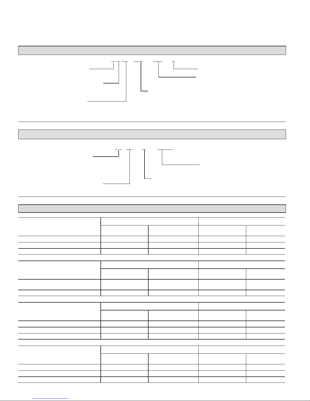
Model Number Identification
I. OVERVIEW
P 17 036− −
X 2−
Refrigerant Type
X = R-410A
Unit Type
P = Heat Pump Outdoor Unit
Series
Typical Serial Number Identification
5
Location Code
19 = Saltillo, Mexico
58 = Marshalltown, IA
Year Code
08 = 2008
09 = 2009
10 = 2010
8 09 C
230
Minor Revision Number
Voltage
230 = 208/230V-1ph-60hz
Nominal Cooling Capacity
024 = 2 tons
030 = 2.5 tons
036 = 3 tons
042 = 3.5 tons
048 = 4 tons
060 = 5 tons
05716
5 (or 6) Digit Unique Number
Month Code
A = January
B = February
C = March
Specifications
Unit Outdoor Fan
Model Number
XP17-024-230-01, -02, -03, -04, -05 62 10 lbs. 0 oz. 5 26.2
XP17-024-230-06. -07 63 10 lbs. 0 oz. 5 26.2
XP17-024-230-08 63 9 lbs. 10 oz. 5 26.2
Model Number
XP17-030-230-01, -02, -03, -04, -05, -06,
-07
XP17-030-230-08, -09 67 9 lbs. 12 oz. 5 26.2
Model Number
XP17-036-230-01, -02, -03, -04, -05 70 10 lbs. 2 oz. 5 26.2
XP17-036-230-07 71 10 lbs. 2 oz. 5 26.2
XP17-036-230-08 71 9 lbs. 12 oz. 5 26.2
Model Number
XP17-042-230-01, -02, -03, -04, -05, -06 71 11 lbs. 0 oz. 5 26.2
XP17-042-230-07 72 11 lbs. 0 oz. 5 26.2
XP17-042-230-08 72 10 lbs. 10 oz. 5 26.2
XP17
Sound Rating Number
Sound Rating Number
Sound Rating Number
Sound Rating Number
1
(dB)
1
(dB)
67 10 lbs. 2 oz. 5 26.2
1
(dB)
1
(dB)
Factory Refrigerant
Unit Outdoor Fan
Factory Refrigerant
Unit Outdoor Fan
Factory Refrigerant
Unit Outdoor Fan
Factory Refrigerant
Charge
Charge
Charge
Charge
2
2
2
2
Number of Blades Diameter - inches.
Number of Blades Diameter - inches.
Number of Blades Diameter - inches.
Number of Blades Diameter - inches.
Page 2
Page 3
Unit Outdoor Fan
Model Number
Sound Rating Number
(dB)
1
Factory Refrigerant
Charge
2
Number of Blades Diameter - inches.
XP17-048-230-01, -02, -03, -04, 05, -06 71 14 lbs. 0 oz. 5 26.2
XP17-048-230-07 73 14 lbs. 0 oz. 5 26.2
XP17-048-230-08 73 13 lbs. 10 oz. 5 26.2
Unit Outdoor Fan
Model Number
XP17-060-230-01, -02, -03, -04, 05, -06,
-07
Sound Rating Number
(dB)
1
73 14 lbs. 8 oz. 5 26.2
Factory Refrigerant
Charge
2
Number of Blades Diameter - inches.
XP17-060-230-08 73 14 lbs. 2 oz. 5 26.2
1
Tested according to AHRI Standard 270-2008 test conditions.
2
Refrigerant charge sufficient for 15 feet length of refrigerant lines.
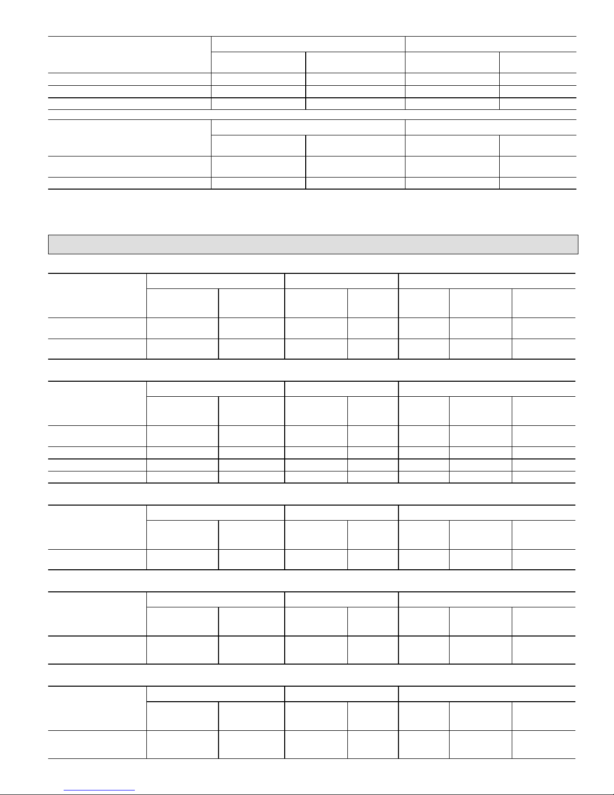
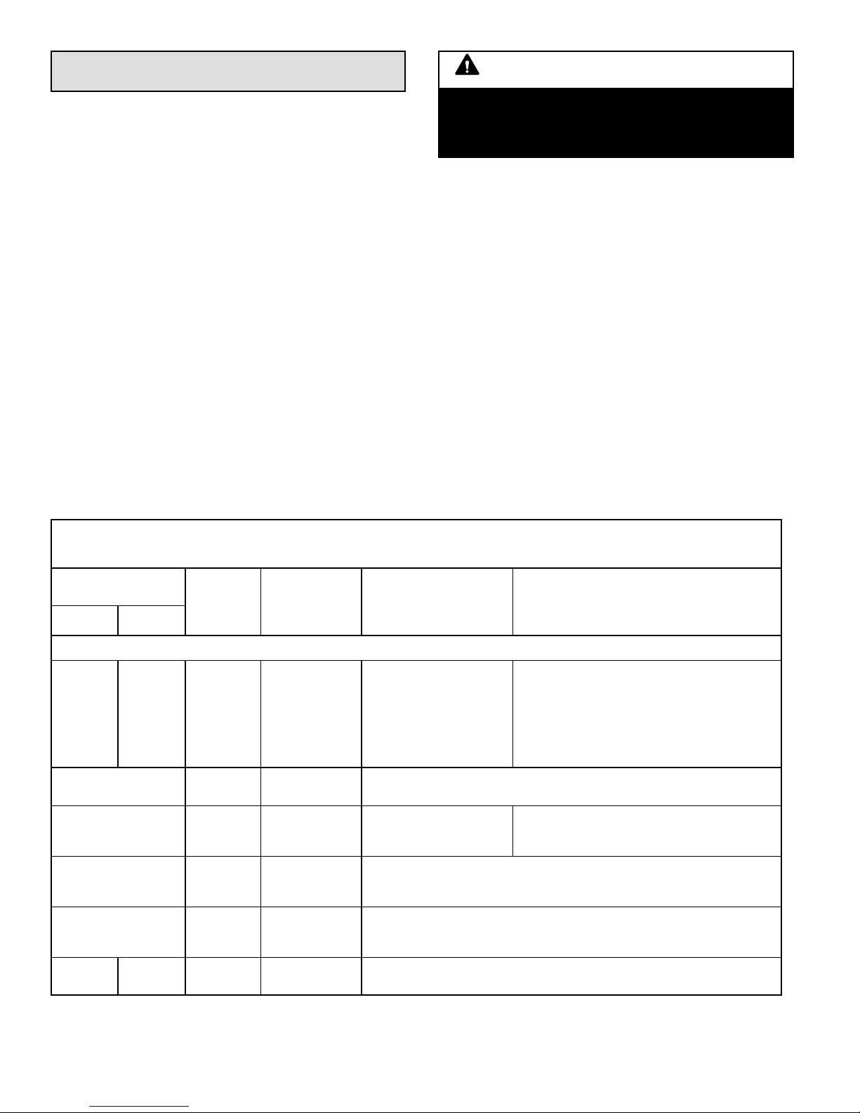
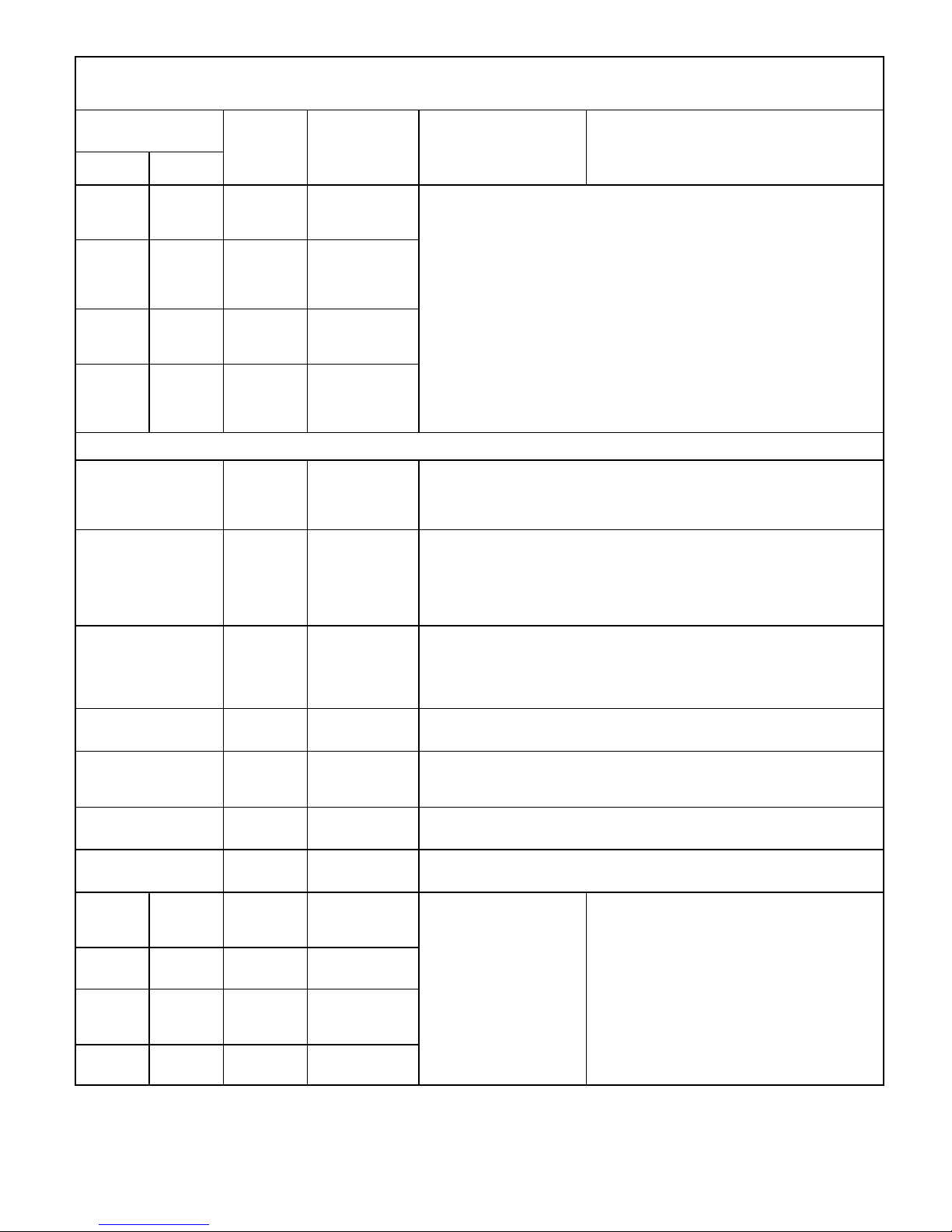
Electrical Data
208/230V-60 Hz-1 Ph
Unit Compressor Condenser Fan
Model Number
XP17-024-230-01, -02,
-03, -04
XP17-024-230-05, -06,
-07. -08
Maximum Over-
current Protection
(amps)
1
30 18.9 13.5 58.3 1/3 400 2.0
30 20.0 13.5 58.3 1/3 400 2.0
Minimum
Circuity
Ampacity
2
Rated Load
Amps (RLA)
Locked
Rotor Amps
(LRA)
Motor HP Nominal RPM
Full Load
Amps (FLA)
208/230V-60 Hz-1 Ph
Unit Compressor Condenser Fan
Model Number
XP17-030-230-01, -02,
-03, -04
Maximum Over-
current Protection
(amps)
1
30 19.6 14.1 73.0 1/3 450 2.0
Minimum
Circuity
Ampacity
2
Rated Load
Amps (RLA)
Locked
Rotor Amps
(LRA)
Motor HP Nominal RPM
Full Load
Amps (FLA)
XP17-030-230-05, -06 30 20.0 14.1 73.0 1/3 450 2.0
XP17-030-230-07 30 20.4 14.1 73.0 1/3 450 2.0
XP17-030-230-08, -09 30 20.0 14.1 73.0 1/3 450 2.0
208/230V-60 Hz-1 Ph
Unit Compressor Condenser Fan
Model Number
XP17-036-230-01, -02,
-03, -04, -05, -07, -08
Maximum Over-
current Protection
(amps)
1
35 22.9 16.7 79.0 1/3 600 2.0
Minimum
Circuity
Ampacity
2
Rated Load
Amps (RLA)
Locked
Rotor Amps
(LRA)
Motor HP Nominal RPM
Full Load
Amps (FLA)
208/230V-60 Hz-1 Ph
Unit Compressor Condenser Fan
Model Number
XP17-042-230-01, -02,
03, -04, -05, -07, -07,
-08
Maximum Over-
current Protection
(amps)
1
40 24.4 17.9 107.0 1/3 600 2.0
Minimum
Circuity
Ampacity
2
Rated Load
Amps (RLA)
Locked
Rotor Amps
(LRA)
Motor HP Nominal RPM
Full Load
Amps (FLA)
Model Number
XP17-048-230-01, -02,
-03, -04, -05, -06, -07,
-08
Maximum Over-
current Protection
(amps)
1
50 29.3 21.8 117.0 1/3 675 2.0
XP17
208/230V-60 Hz-1 Ph
Unit Compressor Condenser Fan
Minimum
Circuity
Ampacity
2
Rated Load
Amps (RLA)
Locked
Rotor Amps
(LRA)
Motor HP Nominal RPM
Page 3
Full Load
Amps (FLA)
Page 4
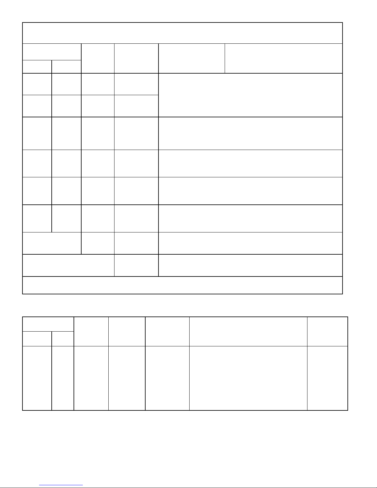
208/230V-60 Hz-1 Ph
Unit Compressor Condenser Fan
Model Number
XP17-060-230-01, -02,
-03, -04, -05, -06, -07,
-08
1
HACR type circuit breaker or fuse.
2
Refer to National or Canadian Electrical Code manual to determine wire, fuse and disconnect size requirements.
Maximum Over-
current Protection
(amps)
1
60 35.0 26.4 134.0 1/3 675 2.0
Minimum
Circuity
Ampacity
2
Rated Load
Amps (RLA)
Locked
Rotor Amps
(LRA)
Motor HP Nominal RPM
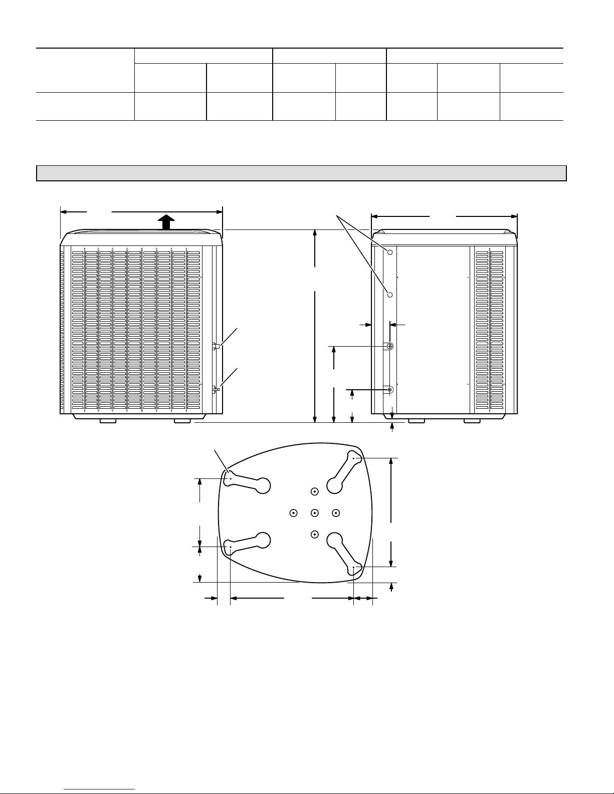
Unit Dimensions -- Inches (Millimeters)
Full Load
Amps (FLA)
39-1/2
(1003)
DISCHARGE AIR
ELECTRICAL INLETS
37 (940) [-024 THRU -042] 47
(1194) [-048 AND -060]
VAPOR LINE
INLET
LIQUID LINE
INLET
4-7/16
18-1/2
(470)
(113)
8 (203)
1 (25)
SIDE VIEW ACCESS VIEW
UNIT SUPPORT
FEET
35-1/2
(902)
16-7/8
(429)
8-3/4
(222)
3-1/8
(79)
XP17
30-3/4
(781)
BASE WITH ELONGATED LEGS
Page 4
26-7/8
(683)
3-3/4 (95)
4-5/8
(117)
Page 5
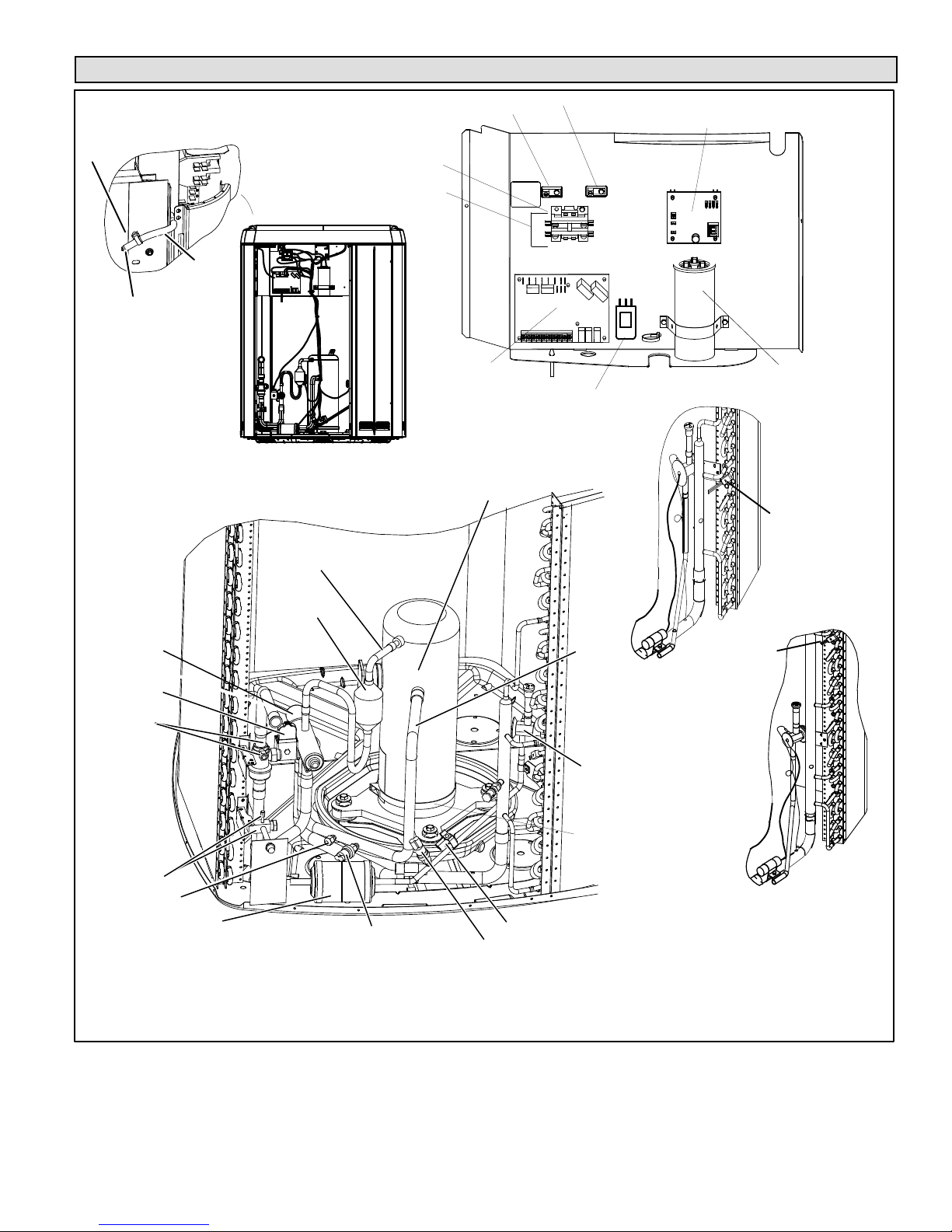
Typical Unit Parts Arrangement
WIRE TIE
OUTDOOR AMBIENT
TEMPERATURE
SENSOR (RT13)
SLEEVE
SECOND GROUND LUG FOR SOURCESOURCE
CONTACTOR-1POLE (K1-1)
HIGH VOLTAGE FIELD
DISCHARGE
LINE
CONNECTIONS
CONTROL (A175)
GROUND LUG
HEAT PUMP
EXTERNAL SURGE
PROTECTION USED ON
XP17-XXX-230-01 AND -02
ONLY). LATER VERSIONS
INCORPORATE FEATURE
INTO FAN MOTOR.
COMPRESSOR
FAN MOTOR CONTROL (A177)
CONTROL BOX
RT21 — MODELS
-024, - 030, -036
AND -042 (12
TUBES UP)
CAPACITOR (C12)
REVERSING
VALV E
REVERSING
VALV E
SOLENOID (L1)
VAPOR VALVE
AND GAUGE
PORT
TRUE SUCTION
LINE PORT
LIQUID VALVE AND
GAUGE PORT
LIQUID LINE
BI-FLOW FILTER
DRIER
MUFFLER
LOW PRESSURE
SWITCH (S87)
TRUE
SUCTION
LINE
CHECK EXPANSION
VALV E
HR1 CRANKCASE
HEATER
CRANKCASE HEATER THERMOSTAT
(S40)
HIGH PRESSURE SWITCH
(S4)
MODELS -048
AND -060
24 TUBES UP
XP17
Figure 1. Typical Parts Arrangement
Page 5
Page 6
IMPORTANT
This unit must be matched with an indoor coil as
specified in Lennox' Product Specification bulletin.
Coils previously charged with HCFC-22 must be
flushed.
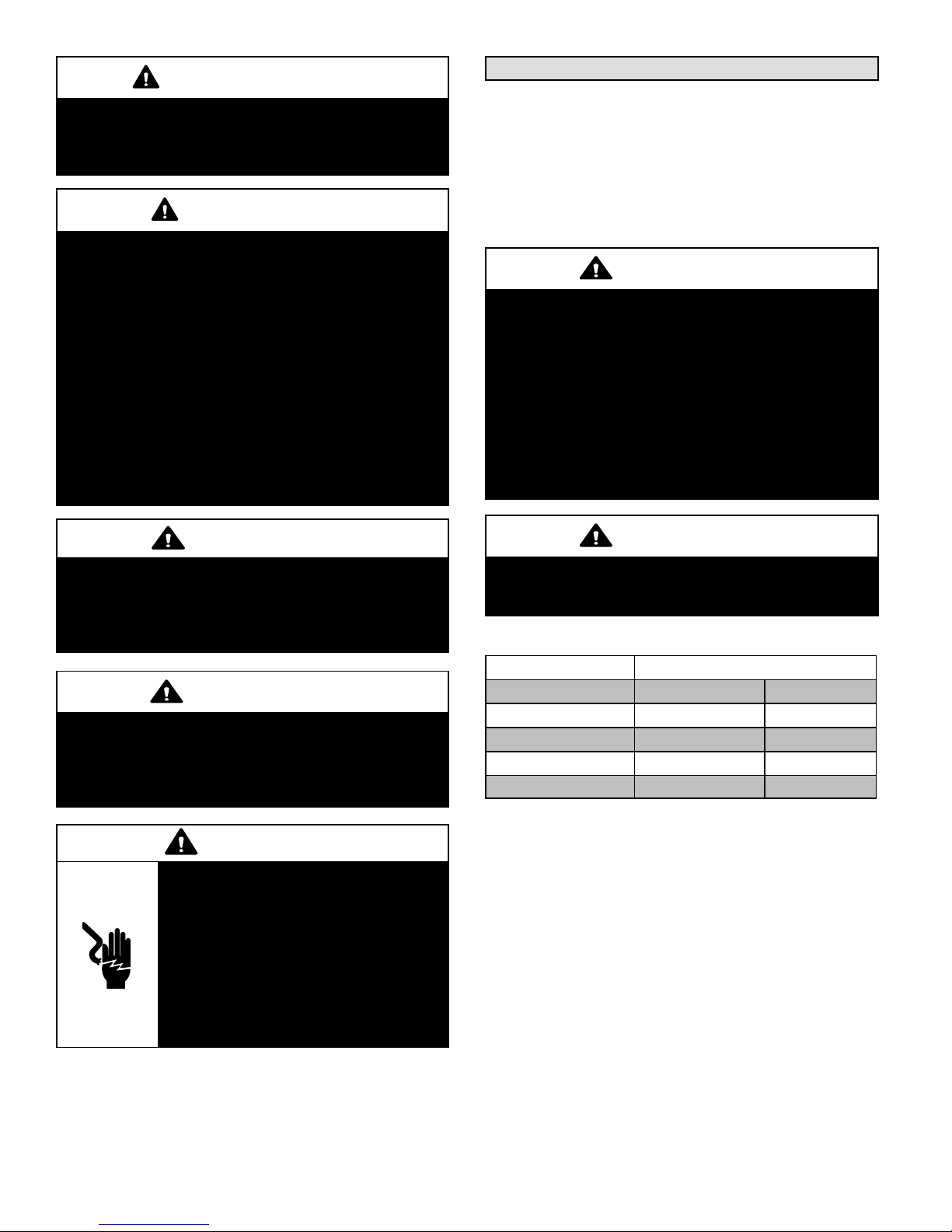
WARNING
This product and/or the indoor unit it is matched with may
contain fiberglass wool.
Disturbing the insulation during installation,
maintenance, or repair will expose you to fiberglass wool
dust. Breathing this may cause lung cancer. (Fiberglass
wool is known to the State of California to cause cancer.)
Fiberglass wool may also cause respiratory, skin, and
eye irritation.
To reduce exposure to this substance or for further
information, consult material safety data sheets available
from address shown below, or contact your supervisor.
Lennox Industries Inc.
P.O. Box 799900
Dallas, TX 75379-9900
Operating Gauge Set
These instructions are intended as a general guide and do
not supersede local codes in any way. Consult authorities
who have jurisdiction before installation.
TORQUE REQUIREMENTS
When servicing or repairing HVAC components, ensure
the fasteners are appropriately tightened. Table 1 lists
torque values for fasteners.
IMPORTANT
Only use Allen wrenches of sufficient hardness (50Rc Rockwell Harness Scale minimum). Fully insert the
wrench into the valve stem recess.
Service valve stems are factory-torqued (from 9 ft-lbs for
small valves, to 25 ft-lbs for large valves) to prevent
refrigerant loss during shipping and handling. Using an
Allen wrench rated at less than 50Rc risks rounding or
breaking off the wrench, or stripping the valve stem
recess.
See the Lennox Service and Application Notes #C-08-1
for further details and information.
CAUTION
Physical contact with metal edges and corners while
applying excessive force or rapid motion can result in
personal injury. Be aware of, and use caution when
working nearby these areas during installation or while
servicing this equipment.
IMPORTANT
The Clean Air Act of 1990 bans the intentional venting of
refrigerant (CFCs, HCFCs AND HFCs) as of July 1, 1992.
Approved methods of recovery, recycling or reclaiming
must be followed. Fines and/or incarceration may be
levied for noncompliance.
WARNING
Electric Shock Hazard. Can cause injury
or death. Unit must be grounded in
accordance with national and local
codes.
Line voltage is present at all components
when unit is not in operation on units with
single‐pole contactors. Disconnect all
remote electric power supplies before
opening access panel. Unit may have
multiple power supplies.
The XP17 is a high efficiency residential split-system heat
pump unit, which features a one stage scroll compressor
and HFC-410A refrigerant. Units are available in 2, 2.5, 3,
3.5, 4 and 5-ton sizes. The series is designed for use with
an expansion valve only (approved for use with HFC-410A)
in the indoor unit.
XP17
IMPORTANT
To prevent stripping of the various caps used, the
appropriately sized wrench should be used and fitted
snugly over the cap before tightening.
Table 1. Torque Requirements
Parts Recommended Torque
Service valve cap 8 ft.- lb. 11 NM
Sheet metal screws 16 in.- lb. 2 NM
Machine screws #10 28 in.- lb. 3 NM
Compressor bolts 90 in.- lb. 10 NM
Gauge port seal cap 8 ft.- lb. 11 NM
USING MANIFOLD GAUGE SET
When checking the system charge, only use a manifold
gauge set that features low loss anti-blow back fittings.
Manifold gauge set used with HFC-410A refrigerant
systems must be capable of handling the higher system
operating pressures. The gauges should be rated for use
with pressures of 0 - 800 psig on the high side and a low
side of 30” vacuum to 250 psig with dampened speed to
500 psi. Gauge hoses must be rated for use at up to 800
psig of pressure with a 4000 psig burst rating.
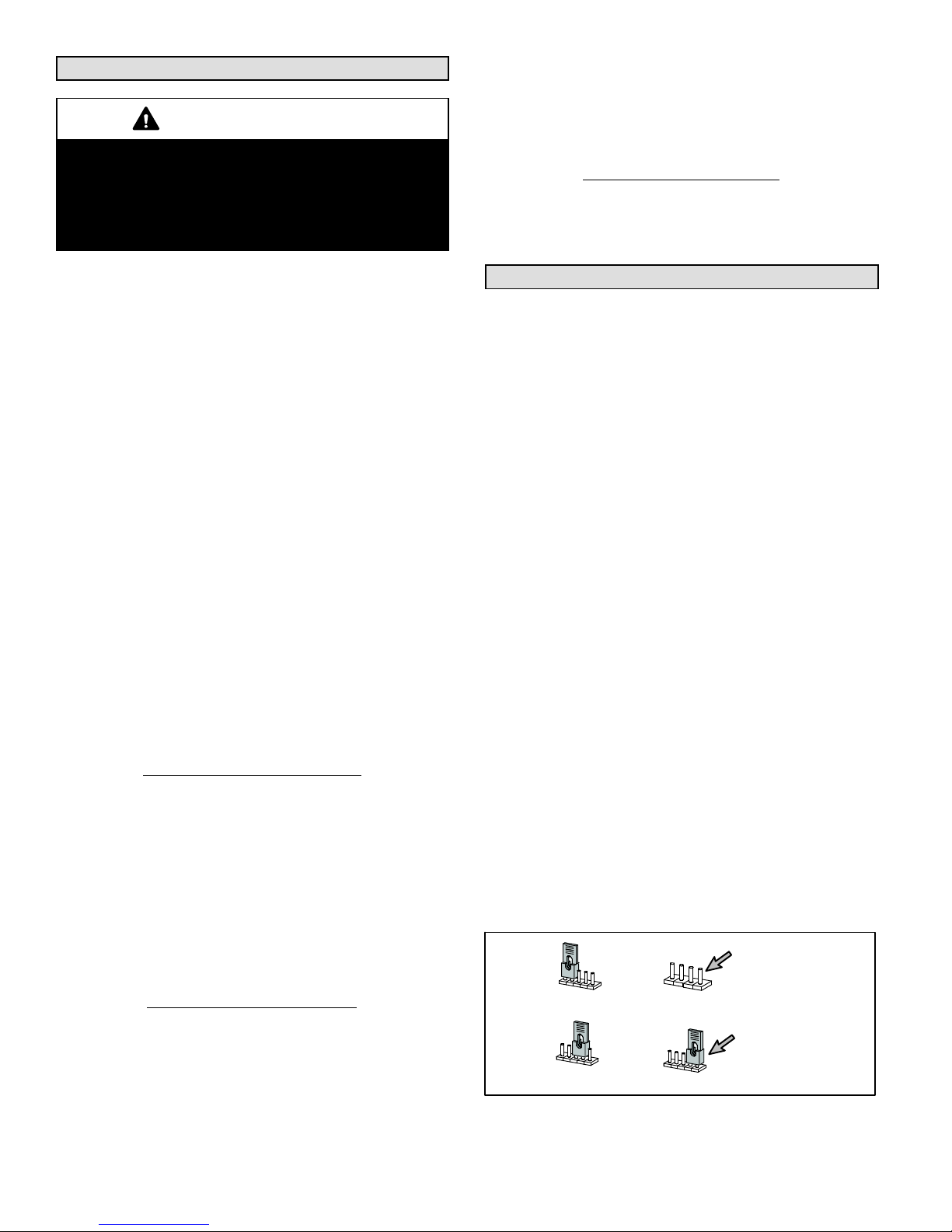
OPERATING SERVICE VALVES
The liquid and vapor line service valves are used for
removing refrigerant, flushing, leak testing, evacuating,
checking charge and charging.
Each valve is equipped with a service port which has a
factory-installed valve stem. Figure 2 provides information
on how to access and operating both angle and ball service
valves.
Page 6
Page 7
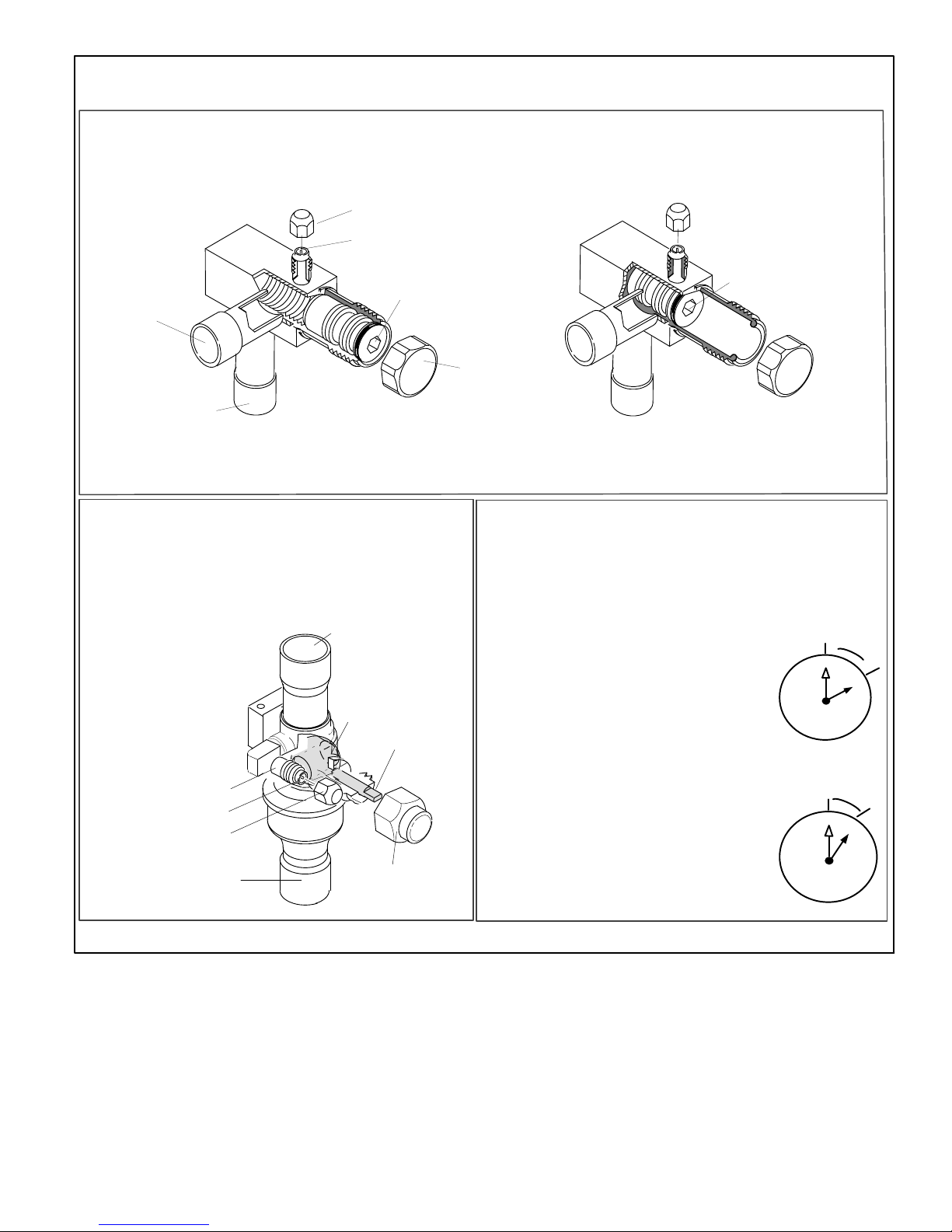
SERVICE VALVES
ANGLE AND BALL
Operating Angle Type Service Valve:
1. Remove stem cap with an appropriately sized wrench.
2. Use a service wrench with a hex-head extension (3/16” for liquid line valve sizes and 5/16” for vapor line valve sizes) to back
the stem out counterclockwise as far as it will go.
SERVICE PORT CAP
SERVICE PORT CORE
(VALVE STEM SHOWN
CLOSED) INSERT HEX
WRENCH HERE
TO INDOOR
UNIT
(VALVE STEM SHOWN OPEN)
INSERT HEX WRENCH HERE
STEM CAP
TO OUTDOOR UNIT
ANGLE-TYPE SERVICE VALVE
(BACK-SEATED OPENED)
When service valve is OPEN, the service port is
open to linE set, indoor and outdoor unit.
Operating Ball Type Service Valve:
1. Remove stem cap with an appropriately sized wrench.
2. Use an appropriately sized wrenched to open. To open valve,
rotate stem counterclockwise 90°. To close, rotate stem
clockwise 90°.
TO INDOOR UNIT
TO OPEN ROTATE STEM
COUNTERCLOCKWISE 90°.
TO CLOSE ROTATE STEM
CLOCKWISE 90°.
SERVICE PORT
SERVICE PORT
SERVICE PORT
CORE
CAP
TO OUTDOOR
UNIT
BALL (SHOWN
CLOSED)
VALV E
STEM
STEM CAP
ANGLE-TYPE SERVICE VALVE
(FRONT-SEATED CLOSED)
WHEN SERVICE VALV E IS CLOSED, THE SERVICE PORT IS
OPEN
TO THE LINE SET AND INDOOR UNIT.
To Access Service Port:
A service port cap protects the service port core from contamination and
serves as the primary leak seal.
1. Remove service port cap with an appropriately sized wrench.
2. Connect gauge set to service port.
3. When testing is completed, replace service port cap and tighten as
follows:
With torque wrench: Finger tighten and
torque cap per table 1.
Without torque wrench: Finger tighten and
use an appropriately sized wrench to turn
an additional 1/6 turn clockwise.
10
9
8
Reinstall Stem Cap:
Stem cap protects the valve stem from damage and serves as the
primary seal. Replace the stem cap and tighten as follows:
With Torque Wrench: Finger tighten and then
torque cap per table 1.
Without Torque Wrench: Finger tighten and
use an appropriately sized wrench to turn an
additional 1/12 turn clockwise.
10
9
8
11
11
7
7
12
6
12
6
1/6 TURN
1
2
4
5
1/12 TURN
1
4
5
3
2
3
NOTE — A label with specific torque requirements may be affixed to the stem cap. If the label is present, use the specified torque.
XP17
Figure 2. Angle and Ball Service Valves
Page 7
Page 8
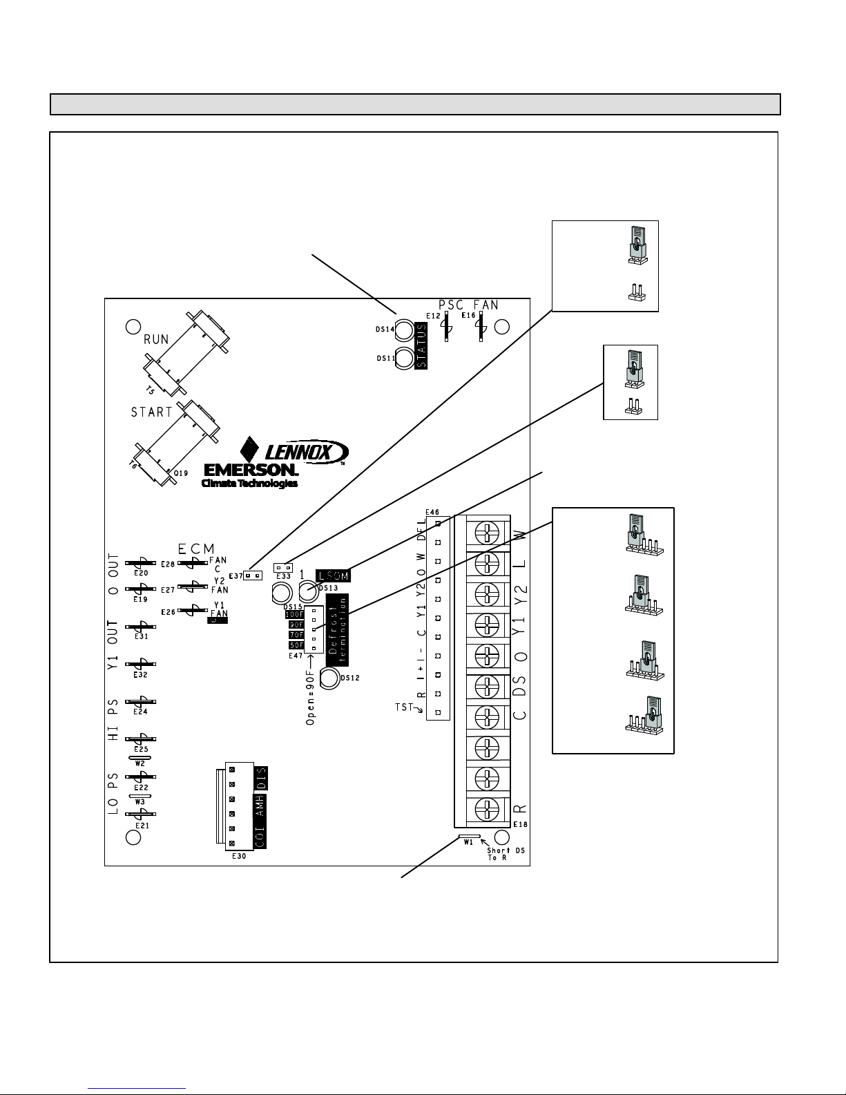
II. SYSTEM OPERATION AND SERVICE
Jumpers, Loops and Terminals (101797-XX)
HEAT PUMP CONTROL — ONE STAGE
DS11 and DS14
LED ALERT CODES
*30
SECOND DELAY
30
0
SECOND DELAY
0
DS13 and DS15
LED ALERT CODES
E47
100
DEGREE
TARGET
100
90
70
50
90
DEGREE
TARGET
100
90
70
E37
COMPRESSOR
SHIFT DELAY
E33
FIELD TEST
50
DEFROST TERMINATION TEMPERATURE
W1
FOR HUMIDITROL — ENHANCED
DEHUMIDIFICATION ACCESSORY
(EDA) APPLICATIONS.
Figure 3. Jumpers, Loop and Terminals (101792-xx)
70
DEGREE
TARGET
*50
DEGREE
TARGET
100
100
90
70
50
90
70
50
XP17
Page 8
Page 9
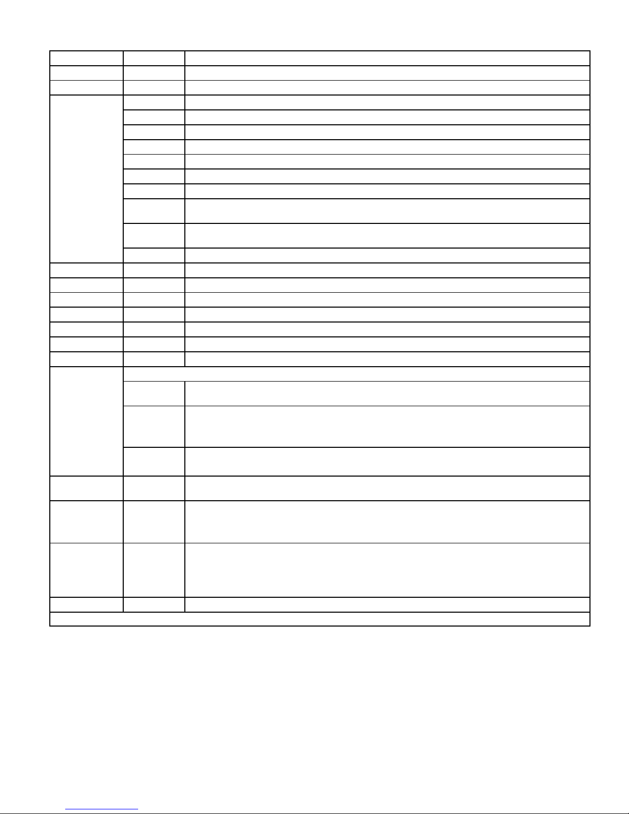
Table 2. Heat Pump Control (A175) Jumper and Terminal Descriptions
Board ID Label Description
E12 PSC Fan 240 VAC output connection for outdoor fan.
E16 PSC Fan 240 VAC input connection for outdoor fan.
W 24VAC output for defrost auxiliary heat output.
L Thermostat service light connection.
Y2 24VAC thermostat input/output for second stage operation of the unit.
Y1 24VAC thermostat input for first stage operation of the unit.
O 24VAC thermostat input for reversing valve operation
E18
E19 and E20 O OUT 24 VAC output connection for reversing valve.
E21 and E22 LO-PS Connection for low-pressure switch (2.4 milliamps @ 18VAC)
E31 and E32 Y1 OUT 24 VAC common output, switched for enabling compressor contactor.
E24 and E25 HS-PS S87 connection for high-pressure switch (E25) and 24VAC (E24) to A177 “R” input.
E26 FAN 1 First Stage and second stage basic and precision dehumidification ECM fan motor 24VDC output connection 1.
E27 FAN 2 Second stage basic and precision dehumidification ECM fan motor 24VDC output connection 2.
E28 FAN C ECM common connection for ECM fan.
E30
E33 Field Test
E37
E47
W1 Short DS To R Cut for Humiditrol — Enhanced Dehumidification Accessory (EDA) applications.
* Factory default setting
DS Humiditrol Input
C 24VAC system common (Build -02 or later)
i-
i+
R 24VAC system power input (Build -02 or later)
Six position square pin header. P4 provides connections for the temperature sensors.
DIS
(YELLOW)
AMB (BLACK)
COIL
(BROWN)
Comp Shift
Delay
50*
70
90
100
Input/Output - RSBus data low. Used in communicating mode only with compatible indoor thermostat. (Build -02
or later)
Input/Output - RSBus data high. Used in communicating mode only with compatible indoor thermostat. (Build
-02 or later)
Not Used
AMB 1 — Outdoor ambient temperature sensor supply.
AMB 2 — Outdoor ambient temperature return.
Range is -40ºF to +140ºF
COIL 1 — Outdoor coil temperature sensor supply.
COIL 2 — Outdoor coil temperature sensor return
This jumper allows service personnel to defeat the timed off control, initiate or terminate a defrost and field
programming of unit capacity feature.
The heat pump control has a field-selectable function to reduce occasional sounds that may occur while the unit
is cycling in and out of the defrost mode. When a jumper is installed on the DELAY pins (E37), the compressor
will be cycled off for 30 seconds going in and out of the defrost mode. Units are shipped with jumper installed on
DELAY pins. If no jumper is installed, the 30 second compressor shift delay is not active.
Seven position square pin header. E47 provides selection of the defrost terminate temperature based on the posi
tion of the selection jumper. The defrost termination temperature is measured by the defrost coil sensor. The
jumper termination pin is factory set at 50°F (10°C). If the temperature jumper is not installed, the default termina
tion temperature is 90°F (32°C). In addition, it provides selection points for enabling the field test mode.
XP17
Page 9
Page 10
System Operations
IMPORTANT
Some scroll compressor have internal vacuum protector
that will unload scrolls when suction pressure goes below
20 psig. A hissing sound will be heard when the
compressor is running unloaded. Protector will reset
when low pressure in system is raised above 40 psig. DO
NOT REPLACE COMPRESSOR.
The heat pump control (A175) provides the following
functions:
Demand defrost algorithm
Field-selectable defrost termination temperatures
Internal switching of outputs
Compressor anti-short-cycle delay.
Five strikes lockout safety function
High (S4) and low (S87) pressure switches
Ambient (RT13), and coil temperatures (RT21)
temperature monitoring and protection.
COMPRESSOR ANTI-SHORT CYCLE DELAY
The heat pump control protects the compressor from:
Short cycling (five minutes) when there is initial power
up
Interruption in power to the unit
Pressure or sensor trips
Delay after Y1 demand is removed.
In non-communicating systems the delay is set for 300
seconds (five minutes) and can not be changed. To
override timer when active or inactive, place a jumper on
the field test pins between 1 and 2 seconds.
In communicating system, the iComfort-enabled
thermostat has a separate built-in 5-minute non-adjustable
short cycle protection.
Resetting Anti-Short Cycle Delay
The FIELD TEST pins (E33) on the heat pump control can
be jumpered between 1 to 2 seconds to bypass delay.
HIGH (S4) AND LOW (S87) PRESSURE SWITCHES
The unit's pressure switches (LO PS - S87 and HI PS - S4)
are factory-wired into the heat pump control on the LO-PS
and HI-PS terminals, respectively.
Low Pressure Switch (LO-PS) — See figure 30 for low
pressure switch sequence of operation.
High Pressure Switch (HI-PS) — See figure 31 for high
pressure switch sequence of operation.
Pressure Switch Event Settings
The following pressures are the auto reset event value
triggers for low and high pressure thresholds:
High Pressure (auto reset) - trip at 590 psig; reset at
418.
Low Pressure (auto reset) - trip at 25 psig; reset at 40.
COMPRESSOR PROTECTION — FIVE-STRIKE
LOCKOUT SAFETY FUNCTION
The five-strike lockout safety function is designed to
protect the unit's compressor from damage. The five-strike
feature is used for high pressure (S4) and low (S87)
pressure switch trips and W input fault or miswire.
Resetting Five-Strike Lockout
Once the condition has been rectified, power to the heat
pump control's R terminal must be cycled OFF, or a jumper
placed on the FIELD TEST pins between 1- to 2-seconds to
reset the heat pump control.
Defrost System
The heat pump control (A175) measures differential
temperatures to detect when the system is performing
poorly because of ice build-up on the outdoor coil. The
controller self-calibrates (see figure 32) when the defrost
system starts and after each system defrost cycle. The
heat pump control monitors ambient temperature, outdoor
coil temperature, and total run-time to determine when a
defrost cycle is required. The coil temperature sensor is
designed with a spring clip to allow mounting to the outside
coil tubing. The location of the coil sensor is important for
proper defrost operation (see figure 1 for location of coil
sensor).
NOTE - The heat pump control accurately measures the
performance of the system as frost accumulates on the
outdoor coil. This typically will translate into longer running
time between defrost cycles as more frost accumulates on
the outdoor coil before the heat pump control initiates
defrost cycles.
DEFROST OPERATING MODES
The heat pump control board has three operational modes
which are:
Defrost calibration and operation (see figure 32)
Defrost test (see figure 7)
DEFROST TERMINATION TEMPERATURES (E47)
The heat pump control selections are: 50, 70, 90, and
100°F (10, 21, 32 and 38°C). The jumper termination pin is
factory set at 50°F (10°C).
If the temperature jumper is not installed, the default
termination temperature is 90°F (32°C). See figure 32 for
on how this settings affects defrost calibration and defrost
modes.
NOTE - Colder climates could require a high discharge
termination temperature setting to maintain a clear coil.
50
50
IF JUMPER IS
NOT INSTALLED
(90ºF)
FACTORY DEFAULT
(50ºF)
100
DEGREE
TARGET
70
DEGREE
TARGET
100
100
90
70
90
70
90
DEGREE
TARGET
50
DEGREE
TARGET
50
100
90
70
50
100
90
70
Figure 4. Defrost Termination Temperature Settings
XP17
Page 10
Page 11
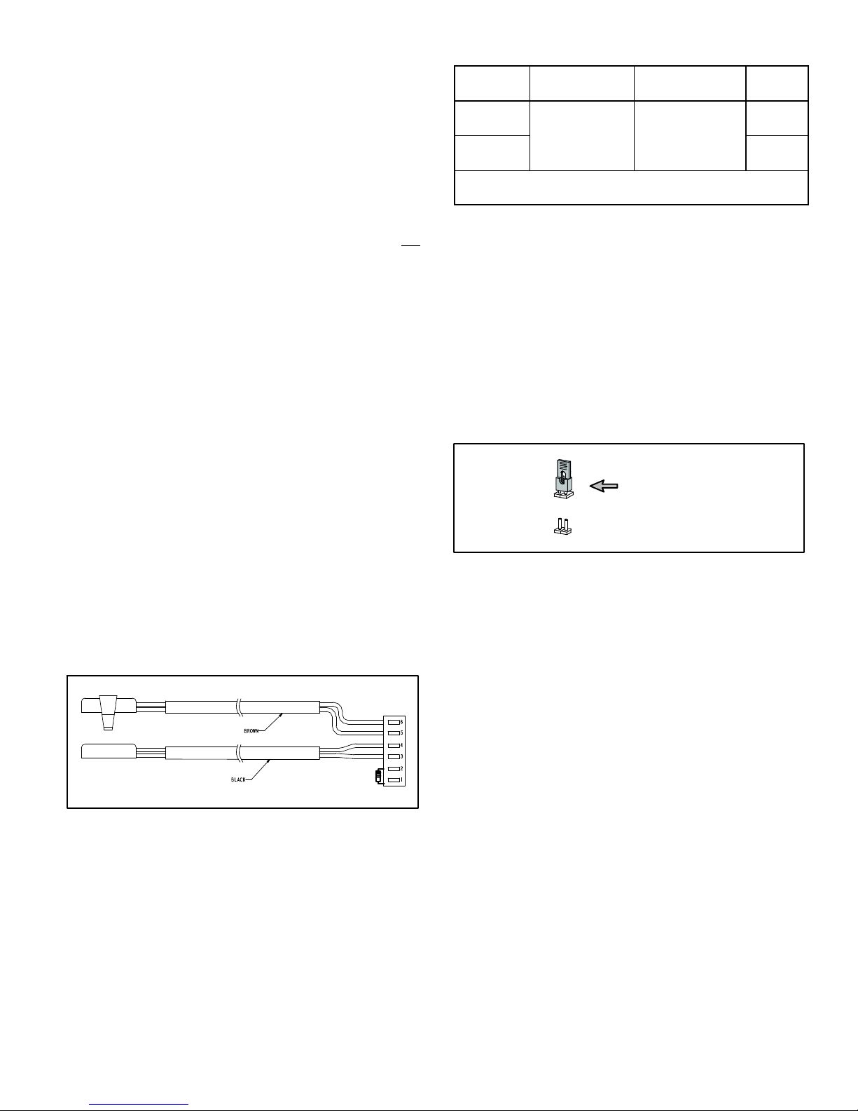
UNIT SENSORS
Sensors connect to the heat pump control through a
field‐replaceable harness assembly that plugs into the
control. Through the sensors, the heat pump control
detects outdoor ambient and coil temperature fault
conditions. As the detected temperature changes, the
resistance across the sensor changes. table 4 shows how
the resistance varies as the temperature changes for both
type of sensors. Sensor resistance values can be checked
by ohming across pins shown in table 3.
Table 3. Sensor Temperature / Resistance Range
Sensor
Outdoor
(Ambient)
Coil
NOTE — Sensor resistance decreases as sensed temperature
increases (see table 4).
Temperature
Range °F (°C)
-40 (-40) to 140
(60)
Resistance values
range (ohms)
280,000 to 3750
Pins/Wire
Color
3 and 4
(Black)
5 and 6
(Brown)
NOTE — When checking the ohms across a sensor, be
aware that a sensor showing a resistance value that is not
within the range shown in table 3, may be performing as
designed. However, if a shorted or open circuit is detected,
then the sensor may be faulty and the sensor harness will
need to be replaced.
Ambient Temperature Sensor (RT13)
See table 3 for sensor range. If the ambient sensor is
detected as being open, shorted or out of the temperature
range of the sensor, the heat pump control will not perform
demand defrost operation. The heat pump control will
revert to time/temperature defrost operation and will
display the appropriate alert code. Heating and cooling
operation will be allowed in this fault condition.
Coil Temperature Sensor (RT21)
See table 3 for sensor range. If the defrost coil sensor is
open, shorted or out of the temperature range of the
sensor, the heat pump control will not perform demand or
time/temperature defrost operation and will display the
appropriate fault code. Heating and cooling operation will
be allowed in this fault condition.
High Discharge Line Temperature Sensor
This model does not use a high discharge line temperature
sensor. The cable assembly attached to the heat pump
control's E30 connection has a 10K resister installed
between pins 1 and 2 as illustrated in figure 5. No alerts or
alarms would be generated if resistor is damage.
COIL TEMPERA
TURE SENSOR
AMBIENT AIR
TEMPERATURE SENSOR
10K RESISTOR
Figure 5. 10k Resistor Location
W Input Fault or Miswire
In case of a W input fault or possible miswire, the system
will function as listed in the sequence of operation in figure
33.
Shift Delay (E37)
The heat pump control has a field-selectable function to
reduce occasional sounds that may occur while the unit is
cycling in and out of the defrost mode. When a jumper is
installed on the DELAY pins (E37), the compressor will be
cycled off for 30 seconds going in and out of the defrost
mode. Units are shipped with jumper installed on DELAY
pins.
*30
SECOND DELAY
30
0
SECOND DELAY
0
Figure 6. Shift Delay Settings
THERMAL PROTECTION SWITCH (S173) COMPRESSOR MOUNTED
Some units are equipped with a compressor mounted
normally closed temperature switch that prevents
compressor damage due to overheating caused by internal
friction. The switch is located on top of the compressor
casing. This switch senses the compressor casing
temperature and opens at 239-257°F (115°C-125°C) to
shut off compressor operation. The auto-reset switch
closes when the compressor casing temperature falls to
151-187°F (66°C-86°C), and the compressor is
re-energized. This single-pole, single-throw (SPST)
bi-metallic switch is wired in series with the 24V Y
input signal to control compressor operation.
FACTORY DEFAULT OR WHEN
JUMPER IS MISSING
XP17
Page 11
Page 12
MULTI-FUNCTION TEST PINS (E33)
Placing the jumper on the field test pins (E33) using a specific sequence allows the technician to:
Clear short cycle lockout
Clear five-strike fault lockout
Cycle the unit in and out of defrost mode
Manually place the unit in defrost mode to clear the coil
When Y1 is energized and 24V power is being applied to the heat pump control (A175), a test cycle can be initiated by placing a jumper on the heat
pump control's TEST pins for 2 to 5 seconds. If the jumper remains on the TEST pins (E33) for longer than five seconds, the heat pump control will
ignore the jumpered TEST pins and revert to normal operation.
The heat pump control will initiate one test event each time a jumper is placed on the TEST pins. For each TEST the jumper must be removed
for at least one second and then reapplied.
Y1 Active
Place a jumper on TEST pins for
longer than one second but less
than two seconds.
Clears any short cycle lockout and
five strike fault lockout function, if
applicable. No other functions will
be executed and unit will continue in
the mode it was operating.
If in COOLING Mode
No further test mode operation will
be executed until the jumper is
removed from the TEST pins and
reapplied.
Place a jumper on TEST pins for
more than two seconds.
Clears any short cycle lockout and
five strike fault lockout function, if
applicable.
ACTIVE
O Line Status
If in DEFROST Mode
The unit will terminate defrost and
enter HEAT MODE uncalibrated
with defrost timer set for a maximum
34 minute test.
INACTIVE
If in HEATING Mode
If no ambient or coil sensor fault exist, unit will go into DEFROST
MODE.
If ambient or coil faults exist (open
or shorted), unit will remain in
HEAT MODE.
NOTE — Heat pump control cannot be force into
defrost mode when the ambient temperature input
from the RT13 sensor is above 65ºF (18ºC).
NOTE — If ambient or coil fault is detected, the board
will not execute the TEST mode.
XP17
If jumper on TEST pins remains in
place for more than five seconds.
The unit will return to HEAT MODE
un−calibrated with defrost timer set
for 34 minutes.
Figure 7. Test Pin (E33) Functions
Page 12
If jumper on TEST pins is removed
before a maximum of five seconds.
The unit will remain in DEFROST
MODE until termination on time or
temperature.
Page 13
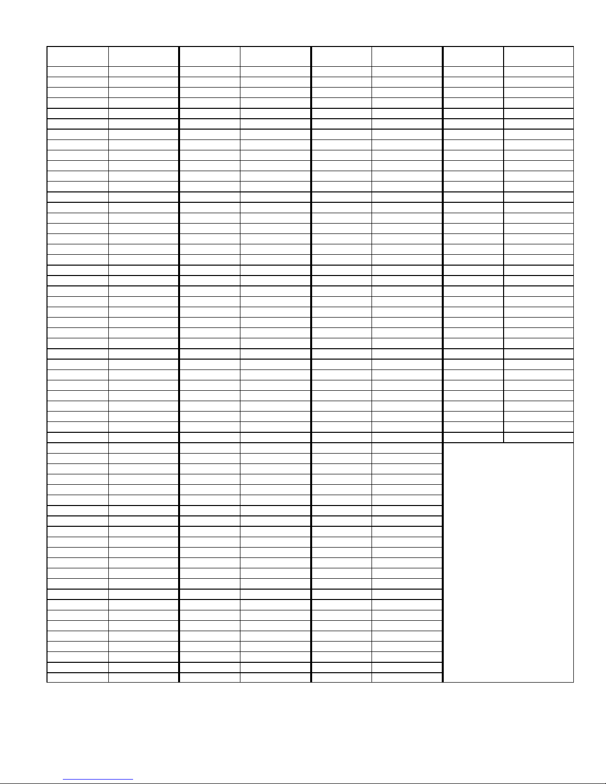
Table 4. RT13 Ambient and RT21 Coil Sensors Temperature / Resistance Range
Degrees
Fahrenheit
136.3 2680 56.8 16657 21.6 44154 -11.3 123152
133.1 2859 56.0 16973 21.0 44851 -11.9 125787
130.1 3040 55.3 17293 20.5 45560 -12.6 128508
127.3 3223 54.6 17616 20.0 46281 -13.2 131320
124.7 3407 53.9 17942 19.4 47014 -13.9 134227
122.1 3592 53.2 18273 18.9 47759 -14.5 137234
119.7 3779 52.5 18607 18.4 48517 -15.2 140347
117.5 3968 51.9 18945 17.8 49289 -15.9 143571
115.3 4159 51.2 19287 17.3 50074 -16.5 146913
113.2 4351 50.5 19633 16.8 50873 -17.2 150378
111.2 4544 49.9 19982 16.3 51686 -17.9 153974
109.3 4740 49.2 20336 15.7 52514 -18.6 157708
107.4 4937 48.5 20695 15.2 53356 -19.3 161588
105.6 5136 47.9 21057 14.7 54215 -20.1 165624
103.9 5336 47.3 21424 14.1 55089 -20.8 169824
102.3 5539 46.6 21795 13.6 55979 -21.5 174200
100.6 5743 46.0 22171 13.1 56887 -22.3 178762
99.1 5949 45.4 22551 12.5 57811 -23.0 183522
97.6 6157 44.7 22936 12.0 58754 -23.8 188493
96.1 6367 44.1 23326 11.5 59715 -24.6 193691
94.7 6578 43.5 23720 11.0 60694 -25.4 199130
93.3 6792 42.9 24120 10.4 61693 -26.2 204829
92.0 7007 42.3 24525 9.9 62712 -27.0 210805
90.6 7225 41.7 24934 9.3 63752 -27.8 217080
89.4 7444 41.1 25349 8.8 64812 -28.7 223677
88.1 7666 40.5 25769 8.3 65895 -29.5 230621
86.9 7890 39.9 26195 7.7 67000 -30.4 237941
85.7 8115 39.3 26626 7.2 68128 -31.3 245667
84.5 8343 38.7 27063 6.7 69281 -32.2 253834
83.4 8573 38.1 27505 6.1 70458 -33.2 262482
82.3 8806 37.5 27954 5.6 71661 -34.1 271655
81.2 9040 37.0 28408 5.0 72890 -35.1 281400
80.1 9277 36.4 28868 4.5 74147 -36.1 291774
79.0 9516 35.8 29335 3.9 75431 -37.1 302840
78.0 9757 35.2 29808 3.4 76745 -38.2 314669
77.0 10001 34.7 30288 2.8 78090 -39.2 327343
76.0 10247 34.1 30774 2.3 79465
75.0 10496 33.5 31267 1.7 80873
74.1 10747 33.0 31766 1.2 82314
73.1 11000 32.4 32273 0.6 83790
72.2 11256 31.9 32787 0.0 85302
71.3 11515 31.3 33309 -0.5 86852
70.4 11776 30.7 33837 -1.1 88440
69.5 12040 30.2 34374 -1.7 90068
68.6 12306 29.6 34918 -2.2 91738
67.7 12575 29.1 35471 -2.8 93452
66.9 12847 28.6 36031 -3.4 95211
66.0 13122 28.0 36600 -4.0 97016
65.2 13400 27.5 37177 -4.6 98870
64.4 13681 26.9 37764 -5.2 100775
63.6 13964 26.4 38359 -5.7 102733
62.8 14251 25.8 38963 -6.3 104746
62.0 14540 25.3 39577 -6.9 106817
61.2 14833 24.8 40200 -7.5 108948
60.5 15129 24.2 40833 -8.2 11114 1
59.7 15428 23.7 41476 -8.8 113400
59.0 15730 23.2 42130 -9.4 115727
58.2 16036 22.6 42794 -10.0 118126
57.5 16345 22.1 43468 -10.6 120600
Resistance
Degrees
Fahrenheit
Resistance
Degrees
Fahrenheit
Resistance
Degrees
Fahrenheit
Resistance
XP17
Page 13
Page 14
System Status, Fault and Lockout LED
Codes
LED codes are displayed using various LEDs located on
the heat pump control (A175). See figure 3 for locations of
heat pump control LEDs.
DS11 AND DS14 — SYSTEM STATUS, FAULT AND
LOCKOUT LED CODES
DS11 (Green) and DS14 (Red) LEDs indicate
non-communicating mode diagnostics conditions that are
listed in table 5.
These LEDs display fault conditions in unit cooling and
heating capacity, dehumidification mode, anti-short cycle
lockout, high and low pressures, discharge line
temperature, outdoor temperature, and discharge sensor
failures.
DS15 AND DS13 — COMPRESSOR FAULT AND
LOCKOUT LED CODES
DS15 (Yellow) and DS13 (Red) LEDs indicate diagnostics
conditions that are listed in table 6.
These LEDs display the most common compressor or
compressor related fault conditions in the unit. When an
abnormal condition is detected, this function
communicates the specific condition through LEDs. The
diagnostic function is capable of detecting both mechanical
and electrical system abnormal conditions.
IMPORTANT
DS15 and DS13 compressor LED fault and lockout
codes do not provide safety protection. The is a
monitoring function only and cannot control or shut down
other devices.
RESETTING FAULT AND LOCKOUT LED CODES
All LED fault and lockout codes can be reset manually or
automatically:
1. Manual Reset
Manual reset can be achieve by one of the following
methods:
Disconnecting R wire from the heat pump's R
terminal.
Turning the indoor unit off an on again
After power up, existing code will display for 60
seconds and then clear.
2. Automatic Reset
After a fault or lockout is detected, the heat pump
control continues to monitor the unit's system and
compressor operations. When/if conditions return to
normal, the alert code is turned off automatically.
Table 5. System Status, Fault and Lockout LED Codes and Related iComfortt-Enabled Thermostat Alert Codes
System fault and lockout LED (DS11 / DS14) alarm codes takes precedence over system status LED codes (cooling, heating stages or
defrost/dehumidification). Only the latest active LED fault or lockout alarm code if present will be displayed. If no fault or lockout codes are active, then
system status LEDs are routinely displayed. See notes 1 and 2 in table below for duration of fast / slow flashes and pause.
Heat Pump Control
LEDs
DS11
Green
Off Off
Simultaneous slow flash
Alternating slow flash
Simultaneous fast
DS14 Red
flashes
iComfortt
-enabled
Thermostat
Display
Not
applicable
Not
applicable
Not
applicable
Moderate /
Critical Alert
Code 180
Condition Possible Cause(s) Solution
SYSTEM STATUS
1. No power (24V) to
heat pump control
terminal's R and C or
Power problem
Normal operation Unit operating normally or in standby mode.
5-minute
anti-short cycle
delay
Ambient sensor
problem
heat pump control
failure.
2. Heat pump control
failure.
Initial power up, safety trip,
end of room thermostat de
mand.
If sensor detects an open, shorted or out-of-temperature range. heat pump control
will revert to time/temperature defrost operation. System will still heat or cool.
1
Check control transformer power (24V).
2
If power is available to control and LED(s) do not
light, replace the heat pump control.
None required (Jumper FIELD TEST (E33) pins to
override)
Alternating fast flash
On On
Moderate /
Critical Alert
Code 417
Not
applicable
Coil sensor
Heat pump
control failure
XP17
problem
If the outdoor coil temperature sensor is detected as being open or shorted, the
heat pump control will not perform defrost operations.
Indicates that heat pump control has an internal component failure. Cycle 24 volt
power to heat pump control. If code does not clear, replace the heat pump control.
Page 14
Page 15
System fault and lockout LED (DS11 / DS14) alarm codes takes precedence over system status LED codes (cooling, heating stages or
defrost/dehumidification). Only the latest active LED fault or lockout alarm code if present will be displayed. If no fault or lockout codes are active, then
system status LEDs are routinely displayed. See notes 1 and 2 in table below for duration of fast / slow flashes and pause.
Heat Pump Control
LEDs
DS11
DS11
Green
Green
DS14 Red
DS14 Red
1 fast flash
Off
then
pause
iComfortt
iComfortt
iComfortt
-enabled
-enabled
-enabled
Thermostat
Thermostat
Thermostat
Display
Display
Display
Not
applicable
Single stage
compressor
heating
SolutionPossible Cause(s)Condition
SolutionPossible Cause(s)Condition
SolutionPossible Cause(s)Condition
On
1 fast flash
then
pause
2 fast
flashes
then
pause
None
None
None
2 fast
flashes
then
pause
Off
On
Not
applicable
Not
applicable
Not
applicable
Moderate
Alert Code
105
Moderate
Alert Code
120
Critical Alert
Code 124
Defrost
Single-stage
compressor
cooling
Dehumidification
mode
Device
communication
failure
Unresponsive
device
Active subnet
controller missing
These are codes that show status of operation whether the system is operating in
either in first or second stage heating or cooling operation, defrost or in the
dehumidification modes.
ALERT STATUS
iComfort-enabled thermostat is unable to communicate with any other device on
the RSBus. Alarm only occurs if a specific device did communicate initially after
power up and communication was later lost. Possible causes are lost connection,
bus short or open, or other device stop responding.
Message could be sent by any device on RSBus if expected response message is
not received from other device. If sent by indoor or heat pump control, device did
not get expected response (incorrect or no response at all) from active Subnet
controller. If sent by the iiComfort-enabled
thermostat, and did not get the
expected response (incorrect or no response at all) from device. Normally this
indicate device malfunction.
Device lost connection to iComfort-enabled thermostat is sending heartbeat
message in one minute intervals. Device sets this alarm if no Heartbeat is
received for three minutes. Normally this indicate lost connection to thermostat, or
thermostat is not working. Alert will clear after valid subnet controller message is
received.
None
None
None
None
Off
Slow flash
Off On
Slow flash Off
On Off
Critical Alert
Code 125
Moderate /
Critical Alert
Code 126
Critical Alert
Code 131
Critical Alert
Code 132
Moderate
Alert Code
410
Critical Alert
Code 411
Moderate
Alert Code
412
Critical Alert
Code 413
Hardware Failure
Internal control
communication
failure
Corrupted control
parameters
Failed flash CRC
check.
Low pressure
fault
Low pressure
switch lockout
High pressure
fault
High pressure
switch lockout
Entire or partial system failure. Alert will clear 300 seconds after fault has
recovered.
Internal communication on heat pump control. Alert will clear 300 seconds after
fault has recovered.
System stored configuration data is corrupted. System will not run.
No operations, heat pump control enters boot loader mode. Alarm will clears after
reset. Refer to communicating thermostat for memory corrupt handling.
1
1
Restricted air flow over in
door or outdoor coil.
2
Improper refrigerant
charge in system.
3
Improper metering device
installed or incorrect op
eration of metering device.
4
Incorrect or improper sen
sor location or connection
to system.
Remove any blockages or restrictions from coils
and/or fans. Check indoor and outdoor fan motor
for proper current draws.
2
Check system charge using approach and sub
cooling temperatures.
3
Check system operating pressures and compare
to unit charging charts.
4
Make sure all pressure switches and sensors
have secure connections to system to prevent
refrigerant leaks or errors in pressure and temper
ature measurements.
XP17
Page 15
Page 16
System fault and lockout LED (DS11 / DS14) alarm codes takes precedence over system status LED codes (cooling, heating stages or
defrost/dehumidification). Only the latest active LED fault or lockout alarm code if present will be displayed. If no fault or lockout codes are active, then
system status LEDs are routinely displayed. See notes 1 and 2 in table below for duration of fast / slow flashes and pause.
Heat Pump Control
LEDs
DS11
DS11
Green
Green
DS14 Red
DS14 Red
Slow flash On
Fast flash On
iComfortt
iComfortt
iComfortt
-enabled
-enabled
-enabled
Thermostat
Thermostat
Thermostat
Display
Display
Display
Moderate
Alert Code
414
Critical Alert
Code 415
Discharge line
temperature fault
Discharge line
temperature
lockout
SolutionPossible Cause(s)Condition
SolutionPossible Cause(s)Condition
SolutionPossible Cause(s)Condition
This code indicates high discharge temperatures. If the discharge line temperature
exceeds a temperature of 279ºF (137ºC) during compressor operation, the control
will de-energize the compressor contactor output (and the defrost output if active).
The compressor will remain off until the discharge temperature has dropped below
225ºF (107ºC).
Off Fast flash
Moderate /
Critical Alert
Code 417
Discharge sensor
fault
The heat pump control (A175) detects open or short sensor or out of temperature
sensor range. This fault is detected by allowing the unit to run for 90 seconds
before checking sensor resistance. If the sensor resistance is not within range
after 90 seconds, the control will raise the alarm.
3 fast
flashes
then
pause
3 fast
flashes
then
pause
Off
On
Moderate /
Critical Alert
Code 418
Moderate /
Critical Alert
Code 419
W output
hardware fault
W output
hardware fault
lockout
When auxiliary heat output is detected as active. Fault in the heat pump control.
Replace heat pump control.
If heat pump control recognizes five output hardware fault events during a single
cooling demand, the heat pump control will initiate a lockout.
3 fast
Off
flashes
then
Critical Alert
Code 421
W external
miswire fault
When auxiliary heat output is detected as active after compressor has been
de-energized.
pause
Simultaneous fast
None
flashes then pause
Fast simultaneous flashing of DS11,
Second-stage
heat lock-in
OEM mode Factory test mode.
If the unit is in non-communicating mode and it goes to second stage due to ambi
ent temperature being below second stage lock-in setting (E48).
DS13, DS14 and DS15
1. Pause duration is two (2) seconds.
2. Fast flash duration is 1/2 second. Slow flash duration is one (1) second.
Table 6. Compressor Fault and Lockout LED Codes and Related iComfortt-Enabled Thermostat Alert Codes
NOTE — See notes 1 and 2 in table below for duration of fast / slow flashes and pause.
Heat Pump Control
LEDs
DS15
Yellow
DS13
Red
Off On
iComfortt
-enabled
Thermostat
Display
Moderate/
3
Critical
Alert
Code 400
Condition
Compressor
internal
overload trip
Possible
Cause(s)
Thermostat
demand signal
Y1 is present, but
compressor not
running
Solution
1
Compressor protector is open.
Check for high head pressure
Check compressor supply voltage
2
Outdoor unit power disconnect is open.
3
Compressor circuit breaker or fuse(s) is open.
4
Broken wire or connector is not making contact.
5
Low or high pressure switch open if present in
the system.
6
Compressor contactor has failed to close.
Clearing Sta
tus
Clears the error
after current is
sensed in the
run and start
winding for two
seconds, ser
vice removed or
power reset.
XP17
Page 16
Page 17
Heat Pump Control
LEDs
DS15
Yellow
DS13
Red
1 flash
then
Off
pause
2 flashes
then
Off
pause
iComfortt
iComfortt
-enabled
-enabled
Thermostat
Thermostat
Display
Display
Critical Alert
Code 401
Critical Alert
Code 402
Condition
Condition
Long run
time.
System
pressure trip
Possible
Possible
Cause(s)
Cause(s)
Compressor is
running extreme
ly long run
cycles.
Indicates the
compressor
protector is open
or missing supply
power to the
compressor.
Solution
Solution
1
Low refrigerant charge.
2
Evaporator blower is not running.
Check blower relay coil and contacts
Check blower motor capacitor
Check blower motor for failure or blockage
Check evaporator blower wiring and connec
tors
Check indoor blower control
Check thermostat wiring for open circuit
3
Evaporator coil is frozen.
Check for low suction pressure
Check for excessively low thermostat setting
Check evaporator airflow (coil blockages or re
turn air filter)
Check ductwork or registers for blockage.
4
Faulty metering device.
Check TXV bulb installation (size, location and
contact)
Check if TXV/fixed orifice is stuck closed or de
fective
5
Condenser coil is dirty
6
Liquid line restriction (filter drier blocked if pres
.
ent)
7
Thermostat is malfunctioning
.
.
Check thermostat sub-base or wiring for short
circuit
Check thermostat installation (location and
level)
1
High head pressure.
Check high pressure switch if present in sys
tem
Check if system is overcharged with refriger
ant
Check for non-condensable in system
2
Condenser coil poor air circulation (dirty,
blocked, damaged).
3
Condenser fan is not running.
Check fan capacitor
Check fan wiring and connectors
Check fan motor for failure or blockage
4
Return air duct has substantial leakage.
Clearing Sta
Clearing Sta
tus
tus
Clears the error
after 30 consec
utive normal run
cycles, or after
power reset.
Clears after four
consecutive
normal com
pressor run
cycles, or after
power reset.
3 flashes
then
pause
4 flashes
then
pause
Off
Off
Moderate
Alert Code
403
Critical Alert
Code 404
Short cycling
Locked rotor
XP17
Compressor is
running less than
three minutes.
Compressor has
a locked out due
to run capacitor
short, bearings
are seized,
excessive liquid
refrigerant.
Page 17
1
Thermostat demand signal is intermittent.
2
Time delay relay or heat pump control is defec
tive.
3
If high pressure switch is present, see flash code
2 information.
1
Run capacitor has failed.
2
Low line voltage (contact utility if voltage at
disconnect is low).
Check wiring connections
3
Excessive liquid refrigerant in the compressor.
4
Compressor bearings are seized.
Clears after four
consecutive
normal com
pressor run
cycles, or after
power reset.
Clears after
power reset or
four normal
compressor
cycles.
Page 18

Heat Pump Control
LEDs
DS15
Yellow
DS13
Red
5 flashes
then
Off
pause
6 flashes
then
Off
pause
7 flashes
then
Off
pause
iComfortt
iComfortt
-enabled
-enabled
Thermostat
Thermostat
Display
Display
Critical Alert
Code 405
Critical Alert
Code 406
Critical Alert
Code 407
Condition
Condition
Open circuit
Open start
circuit
Open run
circuit
Possible
Possible
Cause(s)
Cause(s)
Compressor has
an open circuit
due to power dis
connection, fuse
is open or other
similar condi
tions.
Current not
sensed by Start
transformer.
Current not
sensed by run
transformer.
Solution
Solution
1
Outdoor unit power disconnect is open.
2
Unit circuit breaker or fuse(s) is open.
3
Unit contactor has failed to close.
Check compressor contactor wiring and
connectors
Check for compressor contactor failure
(burned, pitted or open)
Check wiring and connectors between supply
and compressor
Check for low pilot voltage at compressor
contactor coil
4
High pressure switch is open and requires
manual reset.
5
Open circuit in compressor supply wiring or
connections.
6
Unusually long compressor protector reset time
due to extreme ambient temperature.
7
Compressor windings are damaged.
Check compressor motor winding resistance
1
Run capacitor has failed.
2
Open circuit in compressor start wiring or
connections.
Check wiring and connectors between supply
and the compressor S terminal
3
Compressor start winding is damaged.
Check compressor motor winding resistance
1
Open circuit in compressor start wiring or
connections.
Check wiring and connectors between supply
and the compressor R terminal
2
Compressor start winding is damaged.
Check compressor motor winding resistance
Clearing Sta
Clearing Sta
tus
tus
Clears after one
normal com
pressor run
cycle or power
reset.
Clears when
amperage is de
tected in RUN
and START
sensors, or af
ter power reset.
Clears when
amperage is de
tected in RUN
and START
sensors, or af
ter power reset.
1
8 flashes
then
pause
9 flashes
then
pause
Off
Off
Critical Alert
Code 408
Moderate/
Critical Alert
Code 409
Fast simultaneous flashing of DS11,
3
Welded
contactor
Secondary
low voltage
Compressor
always runs
24VAC is below
18VAC.
OEM Mode Factory test mode.
Compressor contactor failed to open.
2
Thermostat demand signal not connected to
module.
1
Control circuit transformer is overloaded.
2
Low line voltage (contact utility if voltage at
disconnect is low).
Check wiring connections
DS13, DS14 and DS15
1. Pause duration is two (2) seconds.
2. Fast flash duration is 1/2 second. Slow flash duration is one (1) second.
3. Initially a moderate status is displayed and is escalated to critical if alarm exists for more than 10 minutes.
Clears after one
normal com
pressor run
cycle or after
power reset.
Clears after
voltage is high
er than 20VAC
for two sec
onds, or after
power reset.
XP17
Page 18
Page 19
Component Field Configuration and
Troubleshooting
FAN MOTOR CONTROL (A177)
This section provides procedures for testing the fan
control.
FAN MOTOR CONTROL LED CODES AND
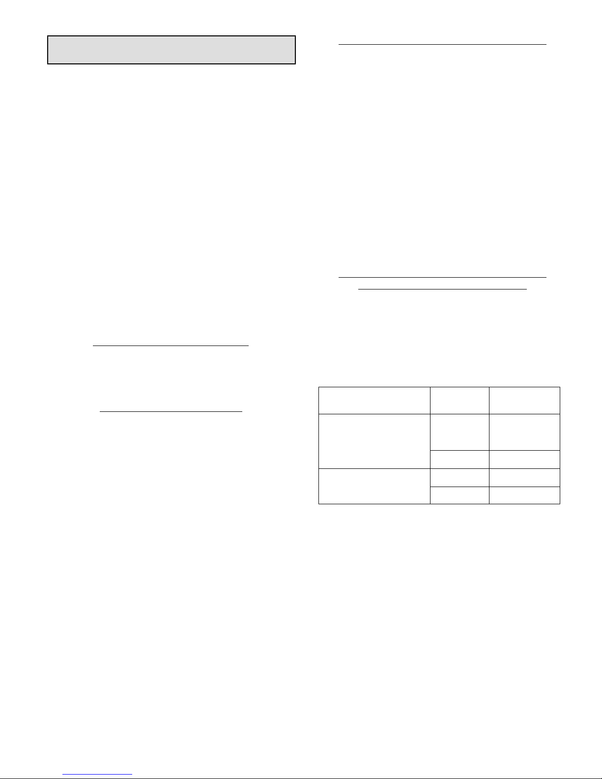
SEQUENCE OF OPERATIONS
During start up, the LED:
1. Display error conditions (see table 9), if present
2. If no errors are detected, then the LED code indicating
stage operation (see table 10) will display the
applicable code and then a long pause.
3. The fan motor speed / RPM (revolutions per minute)
indicator is displayed next (see table 8).
4. After the RPM indicator is displayed, there is a short
pause. The sequence repeats if a thermostat demand
is still present. See figure 8 for LED sequence. See
table 10 for description of flash and pause durations.
FAN MOTOR CONTROL TROUBLESHOOTING
Use the following subsections to verify and test the fan
motor control (A177).
Verifying Jumper Settings (J2)
The unit is shipped from the factory with the default fan
motor speed setting (in RPMs) required for each specific
model. Use the table 8 verify that jumpers are set correctly
for the specific unit.
Verifying LED Status Codes
During start up, the fan motor control (A177) LED will
display any error conditions. If error conditions exist
then no other codes will display. If no error
conditions are present, then the stage status and
and RPM indicator are displayed. Fan motor speeds
are not adjustable for a single stage outdoor unit (see
table 8).
Verifying Correct DC Output Voltage (J2)
The following three methods can be used to determine
whether the fan motor (B4) is operating at the correct
RPMs based on unit size.
1. Use the information provided in table 8 to verify that all
four jumper terminals are set correctly for the specific
size unit.
2. Verify LED RPM indicator is displaying the correct flash
sequence for the applicable size unit (see table 10).
3. Test DC voltage output on the fan motor control's J2
terminals (see figure 9) while under full load and verify
the voltage read to the voltage listed in table 8 for the
applicable size unit.
4. If no voltage is detected at the J2 terminals, verify there
is a Y1 demand at the thermostat and applicable
voltages detected all fan motor control (A177) voltage
inputs, see table 7.
If there is a demand, proceed to the next section for further
testing.
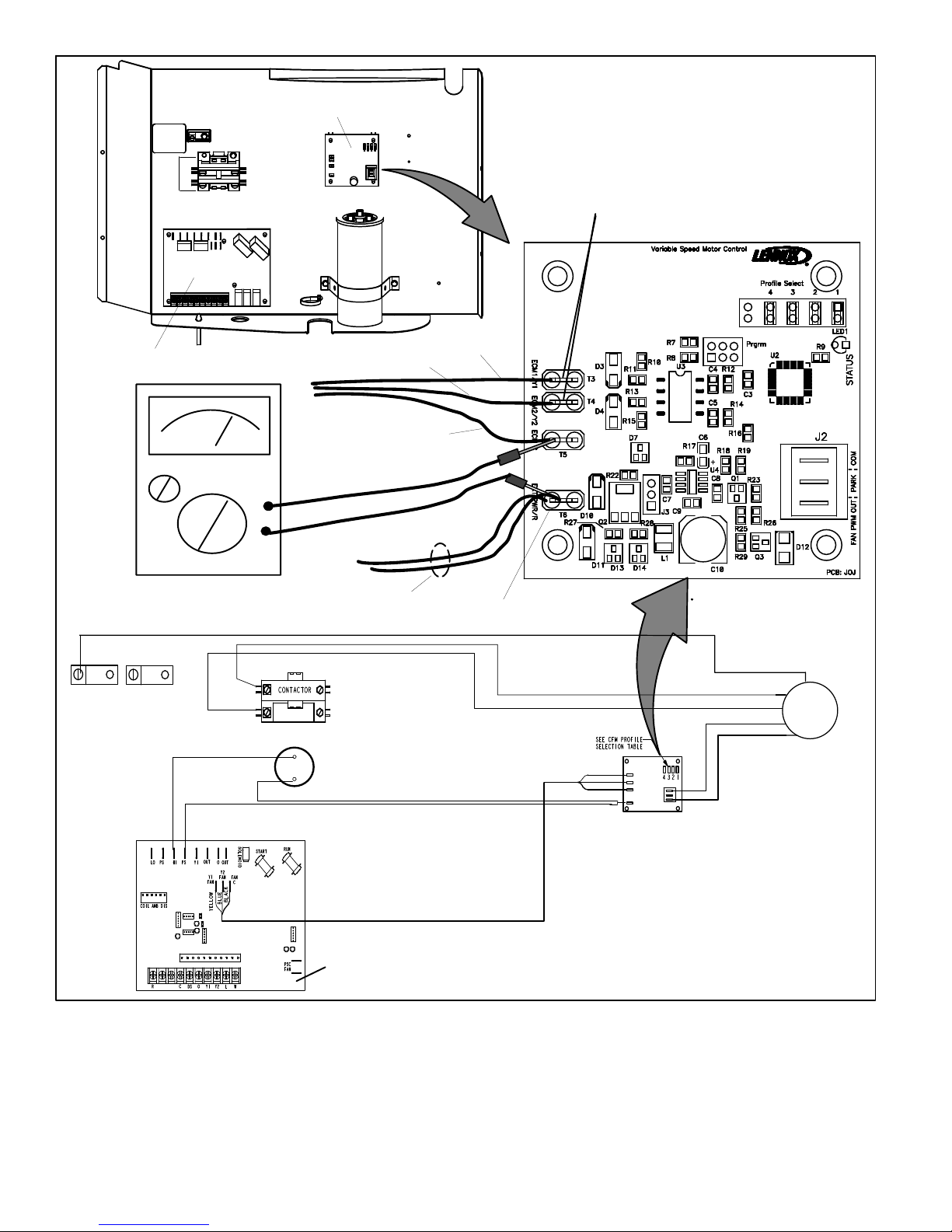
Verifying Correct Input Voltage (ECM/Y1,
ECM/Y2, ECM C and EXT ECM/R)
Using a voltmeter, check voltages on the following fan
motor control inputs using table 7. Voltage will only be
present during a thermostat demand. See figure 10 for test
example.
If correct voltages are detected at applicable inputs during
a demand, and no voltage is present at the J2 terminals,
then fan motor control should be replaced.
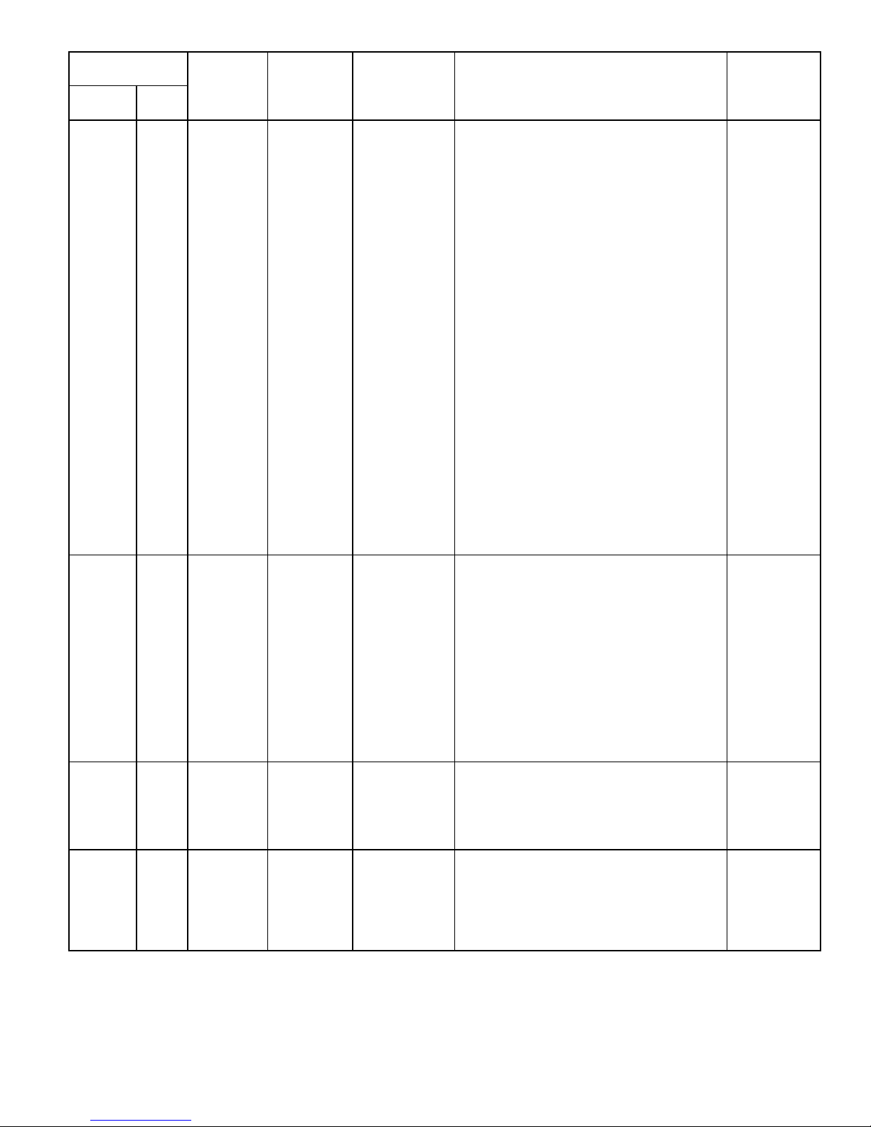
Table 7. Fan Motor Control Voltage Inputs
Input
ECM/Y1 and ECM C
EXT ECM/R and ECM C
Call for
Cooling
YES
NO NONE
YES 24VAC
NO NONE
Voltage
Present
Between
24VDC and 32
VDC
XP17
Page 19
Page 20
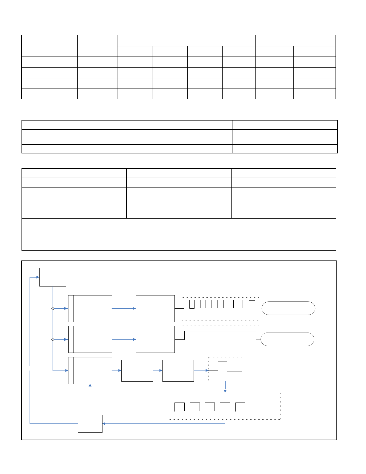
Table 8. One Stage — Fan Motor Control RPM Jumper Settings, LED RPM Indicator and P2 DC
Voltage Outputs
Model LED Code*
4 3 2 1 RPM (J2) DC Volt
XP17-024 5 OFF ON ON ON 400 12.7
XP17-030 6 OFF ON ON OFF 450 14.3
XP17-036, -042 8 OFF OFF ON ON 600 19.2
XP17-048, -060 9 OFF OFF OFF ON 675 21.6
* LED Code indicates fan motor control LED flash sequence. For example, LED Code 9 indicates 9 slow flashes and pause.
CFM Profile Pin Select ECM1/Y1
Table 9. Fan Motor Control Error/Fault LED Codes
Unit Status Fan Motor Control LED Possible Cause
Mismatched RPM Fast Flash with no pause
Internal feedback, PWM does not match
target.
CRC Failure Constant ON. Microcontroller CRC failure.
Table 10. Fan Motor Control (A177) Unit LED Codes
Unit Status Unit Status Fan Motor Control LED
One Stage Operation Low Stage — ECM1/Y1 ONLY One slow flash, then short pause.
RPM Indicator
NOTE — There is a long pause between stage
operation and RPM indicator. See tables 1 and 2
for LED RPM indicator.
Flash Flash = Three flashes per second.
Slow Flash = One flash per second.
Short Pause = Two seconds of OFF time.
Long Pause = Five seconds of OFF time.
RPM Indicator
Appropriate number of flashes (See tables 8
and 2).
YES
DEMAND
BEGINS
MISMATCHED
RPM
CRC FAILURE
SINGLE STAGE
OR EDA
OPERATION
NO
DEMAND
ENDED
MOTOR SPEED
ECM1/Y1
ONLY OR
ECM2/Y2
ONLY
DEFAULT FAN
MOTOR SPEED
USED
DEFAULT FAN
USED
FAN MOTOR
RPM SET PER
JUMPER
SETTINGS
LED CONTINUOUS FAST
FLASH
LED CONSTANT ON
STAGE LED INDICATOR: ONE
SLOW FLASH AND ONE
SHORT PAUSE FOR SINGLE
STAGE OR EDA OPERATION
REPLACE FAN MOTOR
CONTROL BOARD
REPLACE FAN MOTOR
CONTROL BOARD
LED RPM INDICATOR:
EXAMPLE: (2−TON
UNIT) – 5 SLOW
FLASHES AND ONE
LONG PAUSE
Figure 8. Fan Motor Control One Stage LED Sequence of Operation
XP17
Page 20
Page 21
FAN MOTOR CONTROL (A177) —
PULSE-WIDTH MODULATION (PWM)
CFM Profile Pin Select
HEAT PUMP
CONTROL (A175)
CONTROL BOX
VERIFY DC VOLTAGE OUTPUT USING FAN PWM OUT AND
COM TERMINALS. SEE TABLE 8 FOR OPTIMAL DC
VOLTAGE BASED ON CFM PROFILE USED.
J2
COM
COM
PARK
J2
JUMPER
OFF
JUMPER
ON
LED
GREEN
YELLOW
RED
YELLOW
RED
YELLOW
FAN PWM OUT
FAN PWM OUT
HIGH PRESSURE SWITCH (S4)
HEAT PUMP CONTROL (A175)
YELLOW
BLUE
BLACK
YELLOW
YELLOW
FAN MOTOR
CONTROL
GREEN
RED
RED
B4 FAN
MOTOR
BLACK
BROWN
SEE TABLE 8 FOR CFM PROFILE
SELECTION OPTIONS.
Figure 9. Fan Motor Control, Wiring, Jumper Settings, Testing and LED Location
XP17
Page 21
Page 22
FAN MOTOR CONTROL (A177) —
PULSE-WIDTH MODULATION (PWM)
CONTROL BOX
INPUT VOLTAGES DURING DEMAND
ECM/Y1 ONLY - 24VDC
HEAT PUMP
CONTROL (A175)
BLUE WIRE
24
BLACK WIRE
VDC
VAC
ONE YELLOW WIRE FROM PS (E24) TERMINAL ON HEAT PUMP
CONTROL (A175) AND SECOND YELLOW WIRES ON PIGGYBACK
GREEN
TERMINALS GOES TO S4 HIGH PRESSURE SWITCH.
RED
RED
YELLOW
S4 HIGH PRESSURE SWITCH
YELLOW
YELLOW
YELLOW WIRE
EXT PWR/R (24VAC INPUT
DURING DEMAND ONLY)
YELLOW
BLUE
BLACK
YELLOW
YELLOW
FAN MOTOR
CONTROL
GREEN
RED
RED
B4 FAN
MOTOR
BLACK
BROWN
SEE TABLE 8 FOR CFM PROFILE
SELECTION OPTIONS.
Figure 10. Testing for External Power to Fan Motor Control
XP17
HEAT PUMP CONTROL
Page 22
Page 23
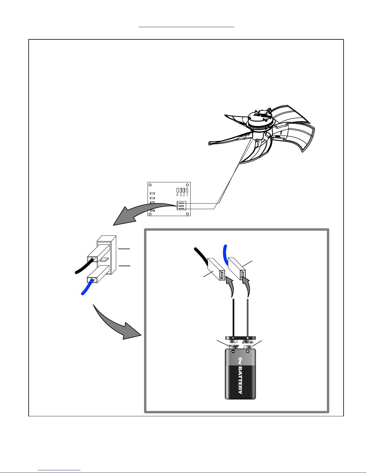
Fan Motor (B4) Test Procedure
A simple test can be used to test the fan motor operation. A fully charged 9V battery will be required for this procedure.
FAN MOTOR TEST
This is a test that will verify that the motor does operate.
1. Verify main (240 volt) power if OFF to unit.
2. Remove both wires (brown and black) from the J2 terminal on the fan motor
control (A177).
3. Room thermostat should be in OFF position (unit in idle mode - no heating or
cooling demands)
4. Turn main power (240 volt) ON to unit.
5. Connect 9 Volt battery to fan motor (B4) plugs as noted in picture
below.
6. Fan motor should run at a reduced fan speed.
7. Fan motor does not run, then replace fan motor assembly.
REMOVE BOTH LEADS
FROM J2 TERMINALS
BLACK LEAD
BROWN LEAD
J2
COM
PARK
FAN PWM OUT
FAN MOTOR CONTROL (A177)
J2
BLACK LEAD
CONNECT B4 FAN MOTOR BLACK
COMMON WIRE TO 9V BATTERY
NEGATIVE TERMINAL
NEGATIVE TERMINAL POSITIVE TERMINAL
BLACK LEAD
BROWN LEAD
BROWN LEAD
CONNECT B4 FAN MOTOR WIRE
TO 9V BATTERY POSITIVE
V
TERMINAL
XP17
FULLY CHARGED 9V BATTERY
Figure 11. Fan Motor (B4) Test
Page 23
Page 24
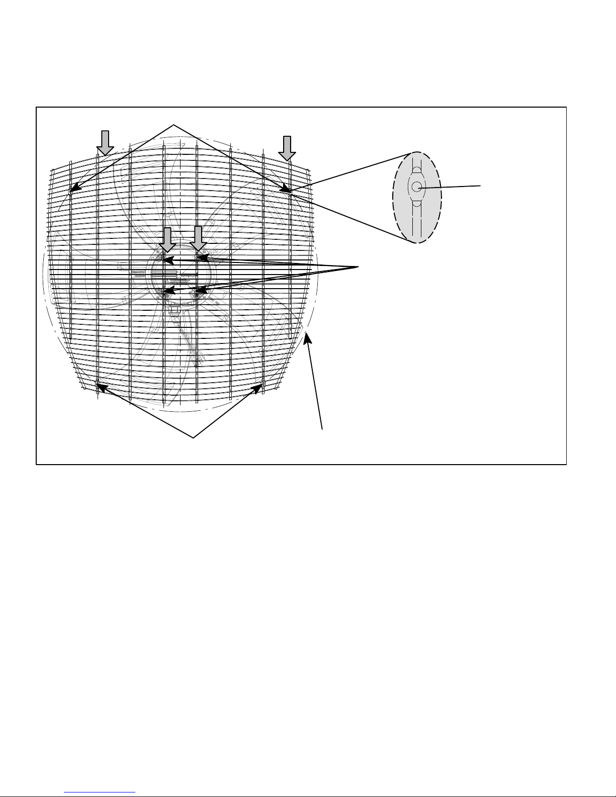
TOP GRILLE OR FAN MOTOR MOUNT ADJUSTMENT FOR FAN CLEARANCE
Sometimes during shipping, either the fan motor mounting or top grille may become out of alignment. This may cause the fan
motor blade to not clear the orifice ring. If this situation occurs, simply adjust either or both the fan motor mount or top grille
positions to allow proper clearance. The top grille four fastener insertion points to the plastic top and motor mount locations
are larger than the fasteners used to secure the grille and fan motor mounts. Use the procedures provided in figure 12 to
adjust for fan clearance.
PUSH
FORWARD
GRILLE MOUNTING
POINTS
PUSH
FORWARD
FASTENER
INSERTION POINT
FAN MOTOR MOUNTING POINTS
THE FOUR MOUNTING POINT HOLES THAT SECURE THE TOP
GRILLE TO THE PLASTIC TOP ARE LARGER THAN THE
FASTENERS USED TO SECURE THE GRILLE. THIS IS ALSO TRUE
FOR THE FOUR FASTENERS SECURING THE FAN MOTOR TO THE
TOP GRILLE. TO PROVIDE MORE CLEARANCE, PREFORM EITHER
OR BOTH OF THE FOLLOWING PROCEDURES.
TOP GRILLE ADJUSTMENT
1. LOOSEN THE FOUR GRILLE MOUNTING FASTENERS AND
PUSH THE GRILLE FORWARD. TIGHTEN MOUNTING
HARDWARE. IF THERE IS STILL INSUFFICIENT CLEARANCE
PROCEED TO STEP 2.
FAN MOTOR POSITION ADJUSTMENT
2. LOOSEN THE FOUR FAN MOTOR GRILLE MOUNTING
FASTENERS AND PUSH THE FAN MOTOR FORWARD.
TIGHTEN MOUNTING HARDWARE.
GRILLE MOUNTING POINTS
Figure 12. Fan Blade Clearance Adjustment
ORIFICE RING
XP17
Page 24
Page 25
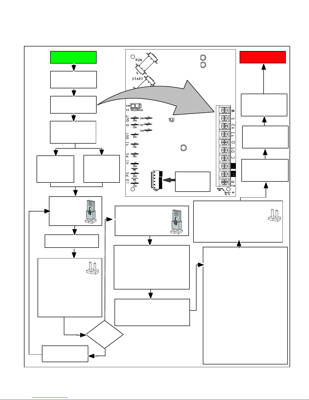
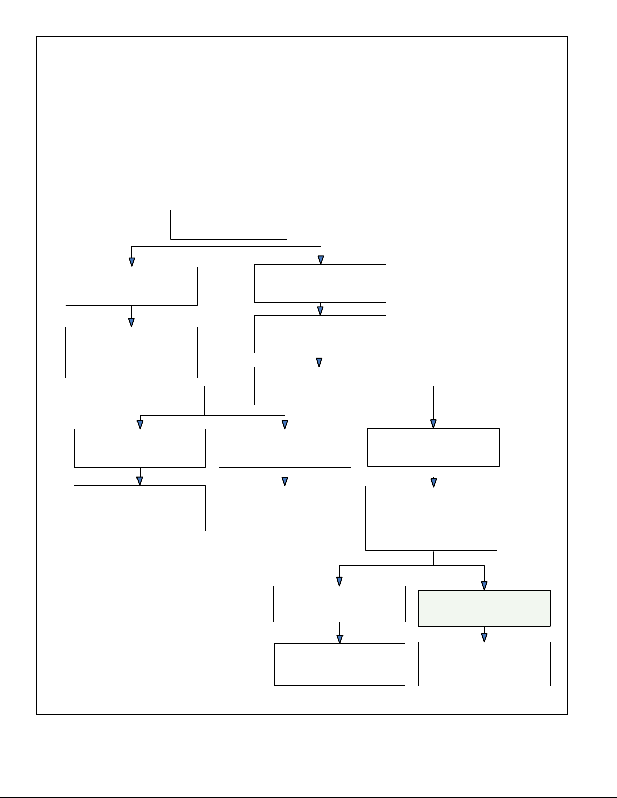
HEAT PUMP CONTROL (A175) UNIT NOMINAL
CAPACITY CODE CONFIGURATION
In a communicating system, if the room thermostat is
indicating either a error code 313, indoor and outdoor unit
capacity mismatch error code, or error code 34, must
program unit capacity for outdoor unit. Use the procedure
provided in figure 13 to set the unit nominal capacity code.
Set room thermostat
Go to control terminal
Remove R wire
from control (24 volt
AC power)
iComfortt
-enabled —
Remove control
wires from i+ and
i- terminals
START
to OFF
strip
Non - iComfortt
enabled —
Remove control
wire from Y1
terminal
DS14 (Red)
DS11 (Green)
Field Test
(E33)
DS12
Communicating
Status Indicator
Sensor harness
must be attached
to air conditioner
control.
TERMINAL STRIP
FINISH
Connect R wire to
control (24 volt AC
power)
Reconnect any control
wiring previously
removed.
Remove R wire from
air conditioner control
(24 volt AC power)
Place jumper
on FIELD TEST
(E33 pins)
Connect R wire to control
(24 volt AC power)
Status LED lights DS11
and DS14 will blink and
then on continuously.
Once both LEDs are on
continuously then
remove jumper
immediately from E33.
If jumper is not removed
immediately from E33, then DS11
and DS14 LEDs will resume
blinking again.
YES
successfully
Remove R wire
from control (24 volt
AC power)
Jumper
removed
NO
Place jumper on FIELD
TEST (E33 pins) within 2 to
4 seconds after removal
The control’s DS11 and DS14 LEDs will
start blinking the Unit Nominal Code at
three (3) second intervals starting at
1-ton through to 6-ton. If a code is not
selected, the control will cycle one more
time through the codes before defaulting
back to the idle mode (simultaneous
slow flash).
Long blink ON red LED (DS14) to
indicate tonnage and solid ON green
LED (DS11) to indicate ½ tonnage.
When the required Unit Capacity Code
is displaying on the LEDs, remove
FIELD TEST jumper from pins (E33).
LEDs will continue to display the
selected unit capacity code for two (2) minutes
before defaulting back to the idle mode
{simultaneous slow flash}, or until the 24 volt
power is cycled to the air conditioner control.
Model
-012
-018
-024
-030
-036
-042
-048
-054
-060
-066
-072
Size
1-ton
1.5-ton
2-ton
2.5-ton
3-ton
3.5-ton
4-ton
4.5-ton
5-ton
5.5-ton
6.0-ton
DS11
Green
LED
OFF
ON
OFF
ON
OFF
ON
OFF
ON
OFF
ON
OFF
DS14
Red LED
1 long flash
1 long flash
2 long flashes
2 long flashes
3 long flashes
3 long flashes
4 long flashes
4 long flashes
5 long flashes
5 long flashes
6 long flashes
Figure 13. Heat Pump Control (A175) Unit Nominal Capacity Code Configuration
XP17
Page 25
Page 26

Jumper and Links (103369-01 and -02)
Communication System
The jumper settings and link are default settings and ONLY control
system operation if configuration settings in the
iComfort-enabled thermostat are not available.
Non−Communicating System
The unit will operate based on jumper settings and R TO DS link on
the MAIN CONTROL. All unit setting changes must be done at the
MAIN CONTROL. The Lennox ComfortSense 7000 thermostat
may be used, as well as other non-communicating electronic-only
thermostats.
7-SEGMENT
DISPLAY
Set up of jumpers on
replacement outdoor
control.
PUSH
BUTTON
(HP ONLY) J4
COMPRESSOR SHIFT DELAY
30
SECOND DELAY
(DEFAULT)
0
SECOND DELAY
30
0
(TWO-STAGE HEAT
PUMP ONLY) J2
SECOND-STAGE LOCK-IN
TEMPERATURE
55
DEGREE
TARGET
50
DEGREE
TARGET
45
DEGREE
TARGET
40
DEGREE
TARGET (DEFAULT)
55
50
45
40
55
50
45
40
MANDATORY CONFIGURATION REQUIREMENTS
— HEAT PUMP CONTROL — TWO-STAGE OP
ERATION
55
50
45
40
1. Set defrost termination temperature (J1) to ensure a completely clear coil before
termination of defrost. Low outdoor temperatures could require higher defrost
termination temperature setting. Factory default setting is 50ºF. If jumper is removed
55
50
45
40
or missing, default is 90ºF.
IMPORTANT — All mandatory configuration requirements (jumpers and link) MUST
be completed prior to starting unit.
2. Second-stage lock-in factory default setting for J2 is 40ºF. If jumper is removed or
missing, default is OFF.
The Lennox iComfort-enabled thermostat must be
used in communicating applications. Refer to page 37
for further information.
NOTE — Fan cycling routine when activated will cycle the
fan ON for five minutes if the outdoor ambient air
temperature is between 15ºF and 35ºF and the
compressor has been OFF for 25 to 30 minutes. This
option is to help reduce the potential for ice build up on the
orifice ring during system OFF cycles that are greater
than 25 to 30 minutes.
J3 ALL UNITS)
FAN CYCLING
SEE NOTE ABOVE FOR FURTHER DETAILS.
JUMPER ON
FAN ON FOR 5 MINUTES
JUMPER OFF
DISABLE (DEFAULT)
ON
OFF
J1 (HP ONLY)
DEFROST TERMINATION TEMPERATURE
100
DEGREE
TARGET
100
90
70
50
100
90
90
70
50
90
DEGREE
TARGET
70
DEGREE
TARGET
50
DEGREE
TARGET
(DEFAULT)
100
90
70
50
(DEFAULT WHEN JUMPER IS
REMOVED OR MISSING)
100
90
70
50
100
90
70
50
DS TO R TWO-STAGE UNIT
ONLY)
Cut for Humiditrol® - Enhanced
Dehumification Accessory (EDA)
applications.
NOTE - LINK NOT APPLICABLE TO
ONE-STAGE UNITS. CUTTING LINK WILL
HAVE NO AFFECT ON OPERATION OF
ONE-STAGE UNITS
.
Figure 14. Jumpers and Links (Outdoor Control Part Numbers 103369-01 and -02)
XP17
Page 26
Page 27

Jumper and Links (103369-03)
J4 - COMPRESSOR
SHIFT DELAY
30
SECOND DELAY
(DEFAULT)
0
SECOND DELAY
30
J2 - SECOND-STAGE
LOCK-IN
TEMPERATURE
(TWO-STAGE HEAT PUMP ONLY)
55
DEGREE
TARGET
50
DEGREE
TARGET
45
DEGREE
TARGET
40
DEGREE
TARGET (DEFAULT)
55
50
55
50
45
55
50
45
55
50
45
40
7-SEGMENT DISPLAY
PUSH BUTTON
J3 - DEFROST AUTO
(HEAT PUMP ONLY)
JUMPER ON PINS 1 AND 2
DEFROST AUTO ENABLED
DEFROST AUTO DISABLED (DEFAULT)
JUMPER ON PINS 2 AND 3
ON
OFF
J1 - DEFROST TERMINATION
0
SECOND-STAGE LOCK-IN
45
40
40
TEMPERATURE
TEMPERATURE
MAX
TARGET
90
MAX
90
DEGREE
TARGET
90
70
DEGREE
TARGET
MAX
MAX
(HEAT PUMP ONLY)
70
50
(DEFAULT WHEN JUMPER IS
REMOVED OR MISSING)
70
50
50
DEGREE
TARGET
(DEFAULT)
90
70
50
MAX
90
90
70
50
MAX
90
70
50
DS TO R LINK - EDA APPLICATION
(TWO-STAGE UNIT ONLY)
40
CUT FOR HUMIDITROL® - ENHANCED
DEHUMIFICATION ACCESSORY (EDA)
APPLICATIONS.
NOTE - LINK NOT APPLICABLE TO SINGLE-STAGE
UNIT. CUTTING LINK WILL HAVE NO AFFECT ON
OPERATION OF SINGLE-STAGE UNITS
.
Figure 15. Jumpers and Links (Outdoor Control Part Number 103369-03)
XP17
Page 27
Page 28

Configuring Unit
For the new outdoor control to work correctly, it MUST BE programmed for unit type (AC or HP and number of stages), unit
capacity and outdoor fan profile (RPM). The new outdoor control has an auto-detection feature that will determine the unit
type. The following set up procedures MUST be done on all new outdoor controls.
Auto-Detection of Unit Type (air conditioner or heat pump and number of stages)
During initial power-up the control will auto-detect the unit
type. The unit type is determine by what is connected to
various outputs on the new control.
The unit capacity and fan speed are manually
configured. Until those parameters are configured the
7-segment display will show 3 bars for the unit capacity
and fan speed.
Anytime there is a connection to O OUT terminal, the
control will detect the unit type as a heat pump.
Anytime there is no connection to O terminal, the
control will detect the unit type as a air conditioner.
Anytime there is a connection to Y2 OUT terminal,
the control will detect the unit as two-stage.
Anytime there is no connection to Y2 terminal, the
control will detect the unit as one-stage.
SEVEN-SEGMENT
BLACK
BLACK
PUSH BUTTON
DISPLAY
OUTDOOR
CONTROL
If the control auto-detects the unit type incorrectly it may be due to the
control being miswired, loose connection or missing connection to
the required control output terminal. Disconnect power to the control,
verify connections, correct wiring and reconnect power. Verify that
the correct unit type is displayed on the seven-segment display.
XP17
Page 28
Page 29

Configuring Unit Type
During initial power-up the control will auto-detect the unit
type. The unit type is automatically determine by what is
connected to Y2 OUT and/or O OUT on the control. The
unit type can be permanently stored in the control's memory by
manually configuring the unit type using the following procedure.
Typically the capacity and fan speed will not be configured and will
display the three dashes for each. For manual configuration of the
unit type, proceed as indicated.
SEVEN-SEGMENT
DISPLAY
PUSH BUTTON
OUTDOOR CONTROL
Yes
To enter unit type
configuration, push and hold
button next to single character
display until dash symbol
appears and immediately
release button. Once dash
starts blinking, proceed to
next step.
Push and hold button until the solid
sequence is displayed on the
seven-segment display and then
immediately release the button.
[This configuration sequence allows the installer to select
a unit type (number / letter combination) that matches the
outdoor type and number of stages.]
Press and hold the button
during the cycling display.
[The sequence will
repeat 5 times and if a
selection is not made the
control will return to idle
mode.]
SELECTED
NOT
Outdoor control is in IDLE mode
(No heating or cooling demand)
No
Turn room thermostat
to OFF
Unit Type / Number of Stages
One stage air conditioner
Two stage air conditioner
1. When the correct unit type is displayed,
2. Push and hold button until selection stops
3. If selection is not made during those three
One stage heat pump
Two stage heat pump
release button immediately. [Display will
start flashing]
flashing during one of the three cycles.
[Release the button]
cycles the control will return to idle mode.
SELECTED
NOT
SELECTED
SELECTED
If three horizontal bars display in any part of the 7-segment
string during power up, the outdoor control did not store that
configuration. (Unit type, capacity or fan RPM. If this happens,
the configuration sequence for that section of the string must
be repeated.
XP17
The outdoor control will store unit type in
memory and will automatically exit the config
uration and reset control.
During power up of the outdoor control, the seven-segment display will show the
stored number of stages unit type, capacity and outdoor fan speed.
PAUSE PAUSE
Page 29
TWO STAGE
HEAT PUMP
CAPACITY
(3-TON)
PROFILE
FAN
Page 30

Configuring Unit Capacity or Fan Profile
OUTDOOR CONTROL
Power-up - Unit capacity (two-digit number) and displayed
represents unit size code (outdoor unit capacity).
During initial power up, the number of stages / unit type, unit
capacity and outdoor fan speed will appear on the 7-segment
display.
If three horizontal bars display in any part of the 7-segment
display string sections during power-up, the outdoor control
did not store that configuration (unit type, capacity or fan
RPM). If this happens, the configuration sequence for that
section of the string must be repeated.
Yes
To enter unit capacity or fan
profile configuration, push
and hold button next to single
character display until dash
symbol appears and
immediately release button.
Once dash starts blinking,
proceed to next step.
Push and hold button until the solid
or sequence is displayed on
the seven-segment display and then
immediately release the button. This
configuration sequence allows the
installer to select a unit type
(number / letter combination) that
matches the outdoor unit type and
number of stages.
Either the or sequence
will repeat 5 times and if a
selection is not made the
control will return to idle mode.
Press and hold the button
during the or cycling
display.
SELECTED
NOTE
UNIT CAPACITY
FAN PROFILE
NOT
SELECTED
Units with EBM motors - The fan motor RPM must be field
set or three bars will appear in the fan profile string section of
the 7-segment display. The factory default is 700 RPM.
Outdoor control is in IDLE mode
(No heating or cooling demand)
Unit Capacity Code
SEVEN-SEGMENT
1-TON
12
1-1/2-TON
18
2-TON
24
2-1/2-TON
30
3-TON
36
3-1/2-TON
42
4-TON
48
5-TON
60
1. When the correct unit capacity or fan profile is
displayed, release button immediately. [Dis
play will start blinking]
2. Push and hold button until selection stops
flashing during one of the three cycles. [Re
lease push button]
3. If selection is not made during those three
cycles the control will return to idle mode.
The outdoor control will store unit type in memory and will automati
cally exit the configuration and reset control.
DISPLAY
PUSH BUTTON
No
Turn room thermostat
to OFF
Fan Profile Code (see notes)
EBM fan motor
with blades
SEE NOTE
See table 11 for
fan profile.
SELECTED
SEE NOTE 1
NOT
SELECTED
If three horizontal bars display in any part of the 7-segment
display string during power-up, the outdoor control did not
store that configuration (unit type, capacity or fan profile). If
this occurs, the configuration sequence for that section of the
string must be repeated.
XP17
During power up of the outdoor control, the seven-segment display will show the
stored number of stages unit type, capacity and outdoor fan speed.
PAUSE PAUSE
2-Stage Heat Pump Capacity (3-Ton) Fan Profile
Page 30
Page 31

Table 11. Fan RPM Profiles
Fan RPM
Profile
0 XC/XP17-024 55 400 55 400 55 400
1 XC/XP17-030 62 450 62 450 62 450
2 Not assigned 69 500 69 500 69 500
3 Not assigned 71 550 76 550 71 550
4 XC/XP17-036 and -042 83 600 83 600 83 600
5 Not assigned 90 650 90 650 90 650
6 XC/XP17-048 and -060 92 675 92 675 92 675
7 Not assigned 97 700 97 700 97 700
8 Not assigned 48 350 55 400 27 200
9 Not assigned 55 400 62 450 27 200
10 XP21-024 58 425 69 500 27 200
11 XC21-024 65 475 76 550 27 200
12 XC/XP21-036 72 525 83 600 30 225
13 Not assigned 79 575 90 650 30 225
Model Number Stage 1
Pulse Width
Modulation
Percentage
Stage 1
Revolutions
Per Minutes
Stage 2
Pulse Width
Modulation
Percentage
Stage 2
Revolutions
Per Minutes
EDA Stage
Pulse Width
Modulation
Percentage
EDA Stage
Revolutions
Per Minutes
14 XC21-048, - 060 and
XP21-048
15 XP21-060 86 625 97 700 30 225
Seven-Segment Alert and System Status
Codes
83 600 92 675 30 225
4. Manual Reset
Manual reset can be achieved by one of the following
methods:
Alert codes are displayed using the seven-segment display
located on the outdoor control.
NOTE — System fault and lockout alarm code displays
takes precedence over system status (cooling, heating
stages or defrost/dehumidification).
The seven-segment will display an abnormal condition
(error code) when detected in the system. A list of the
codes are shown in table 12.
RESETTING ALERT CODES
Alert codes can be reset manually or automatically:
Disconnecting R wire from the main control's R
terminal.
Turning the indoor unit off and back on again
After power up all existing codes are cleared.
5. Automatic Reset
After an alert is detected, the main control continues to
monitor the unit's system and compressor operations.
When/if conditions return to normal, the alert code is
turned off automatically.
XP17
Page 31
Page 32

Table 12. Seven-Segment Display Alert Codes
NOTE — System fault and lockout seven-segment display alarm codes takes precedence over system status codes
(cooling, heating stages or defrost/dehumidification). Only the latest active fault or lockout alarm code if present will be
displayed. If no fault or lockout codes are active, then system status are routinely displayed.
Alert
Codes
E 105
E 120
E 124
E 125
E 126
E 131
E 180
Alarm Description Possible Causes and Clearing Alarm
The outdoor unit has lost
communication with the rest of the
system.
There is a delay in the outdoor unit
responding to the system.
The iComfort-enabled thermostat
has lost communication with the out
door unit for more than 3 minutes.
There is a hardware problem with the
outdoor unit control.
There is an internal communication
problem with the outdoor unit control.
The outdoor unit control parameters are
corrupted
The iComfort-enabled thermostat has
found a problem with the outdoor unit's
ambient sensor.
Equipment is unable to communicate. This may indicate the existence of other alarms / codes. In
most cases errors are related to electrical noise. Make sure high voltage power is separated from
RSBus. Check for mis-wired and/or loose connections between the stat, indoor unit and outdoor
unit. Check for a high voltage source of noise close to the system. This is a self-recoverable error.
Typically, this alarm/code does not cause any issues and will clear on its own. The alarm / code is
usually caused by a delay in the outdoor unit responding to the thermostat. Check all wiring
connections. Cleared after unresponsive device responds to any inquiry
Equipment lost communication with the thermostat. Check the wiring connections, ohm wires and
cycle power. The alarm stops all associated HVAC operations and waits for a heartbeat message
from the unit that's not communicating. The alarm / fault clears after communication is re-estab
lished.
There is a control hardware problem. Replace the outdoor control if the problem prevents operation
and is persistent. The alarm / fault is cleared 300 seconds after the fault recovers
There is an internal hardware problem on the control. Typically the control will re-set itself. Replace
the control if the problem prevents operation and is persistent. The alarm / fault is cleared 300 sec
onds after the fault recovers.
Reconfigure the system. Replace the control if heating or cooling is not available
In normal operation after outdoor control recognizes sensors, the alarm will be sent if valid
temperature reading is lost. Compare outdoor sensor resistance to temperature/resistance charts
in unit installation instructions. Replace sensor pack if necessary. At the beginning of (any)
configuration, furnace or air-handler control will detect the presence of the sensor(s). If detected
(reading in range), appropriate feature will be set as 'installed' and shown in the iComfort-enabled
thermostat 'About' screen. The alarm / fault will clear upon configuration, or sensing normal values.
E 401
E 403
E 409
E 410
E 411
E 412
E 413
Either the compressor ran for more than
18 hours continuously.
The compressor ran for less than 3
minutes to satisfy a thermostat demand
(short-cycling)
The secondary voltage for the outdoor
unit has fallen below 18VAC. If this
continues for 10 minutes, the system
will shut down.
The outdoor unit pressure is below the
required limit.
The low pressure switch has opened 5
times during one cooling cycle. As a
result, the system will shutdown.
The outdoor unit pressure is above the
required limit. The system will shut
down.
The high pressure switch has opened 5
times during one cooling cycle. As a
result, the iComfort -enabled
thermostat will shutdown.
Compressor ran more than 18 hours to satisfy a single thermostat demand. If the unit is 2-stage, the
high-speed will lock-out and the unit will run at low-speed. If it is a HP and ODT <65ºF, the system will
not raise an alarm. Confirm that the system is properly charged with refrigerant. Check for stuck
reversing valve, excessive cooling load and properly sized equipment. Confirm that the evaporator
coil is clean. The alarm clears after 30 consecutive normal run cycles or a power reset.
Compressor runs less than 3 minutes to satisfy a thermostat demand (short-cycling). Confirm that
the system is properly charged with refrigerant. Check the condensation float switch and TXV. The
alarm clears after 4 consecutive normal compressor run cycles or a power reset.
Secondary voltage is below 18VAC. After 10 minutes, operation is discontinued. Check the indoor
line voltage, transformer output voltage. The alarm clears after the voltage is higher than 20VAC for
2 seconds or after a power reset.
Unit pressure is below the lower limit. The system is shutdown. The low pressure switch for
HFC-410A will open at 40PSIG and close at 90PSIG. Confirm that the system is properly charged
with refrigerant. Check TXV, indoor unit blower motor, dirty filters or clogged refrigerant filter. Con
firm that the evaporator coil is clean. The alarm clears after the pressure switch closes or after a
power reset
Open low pressure switch error count reached 5 strikes. The low pressure switch for R410A will
open at 40PSIG and close at 90PSIG. Confirm that the system is properly charged with refrigerant.
Check TXV, indoor unit blower motor, dirty filters or clogged refrigerant filter. Confirm that the
evaporator coil is clean. The alarm clears after a power reset
Unit pressure is above the upper limit. System is shut down. The high pressure switch for HFC-410A
will open at 590PSIG and close at 418PSIG. Confirm that the system is properly charged with
refrigerant. Check condenser fan motor, TXV, indoor unit blower motor, stuck reversing valve or
clogged refrigerant filter. Confirm that the outdoor unit is clean. The alarm clears after 4 consecutive
normal compressor run cycles, the pressure switch closes or a power reset
Open high pressure switch error count reached 5 strikes. System is shut down. The high pressure
switch for HFC-410A will open at 590PSIG and close at 418PSIG. Confirm that the system is prop
erly charged with refrigerant. Check condenser fan motor, TXV, indoor unit blower motor, stuck re
versing valve or clogged refrigerant filter. Confirm that the outdoor unit is clean. The alarm clears
after a power reset.
XP17
Page 32
Page 33

Table 13. Seven-Segment Display Alert Codes (continued)
Alert
Codes
The discharge line temperature is high
E 414
E 415
E 416
E 417
E 418 There is a faulty W output circuit.
E 419
er than the recommended upper limit of
279ºF.
The discharge line temperature has
been consistently higher than the rec
ommended upper limit of 279ºF.
The outdoor coil sensor is either open,
short-circuited or the temperature is out
of sensor range. As a result the outdoor
unit control will not perform any defrost
tempering.
The outdoor unit discharge sensor is ei
ther open, short-circuited or the tem
perature is out of sensor range. As a re
sult the outdoor unit control will not per
form any defrost tempering.
The W output on the outdoor unit has re
ported more than 5 errors. As a result,
the system has shutdown the outdoor
unit.
Alarm Description Possible Causes and Clearing Alarm
Discharge line temperature is > 279ºF. Confirm that the system is properly charged with refrigerant.
Check system operating pressures and compare to unit charging charts in installation manual.
Confirm that the outdoor unit is clean. The alarm clears after the discharge temperature is < 225ºF.
Discharge line high temperature error count reached 5 strikes. Confirm that the system is properly
charged with refrigerant. Check system operating pressures and compare to unit charging charts
in installation manual. Confirm that the outdoor unit is clean. The alarm clears after the discharge
temperature is < 225ºF. The alarm clears after a power reset.
Coil sensor being detected open or shorted, or temperature is out of coil sensor range. Outdoor unit
control will not perform demand or time/temperature defrost operation. System will still heat or cool.
Check the resistance of the coil sensor and compare to temperature resistance chart. Replace coil
sensor if needed. The alarm clears when outdoor unit control detects proper coil sensor readings or
after a power reset.
Outdoor unit control detects open or shorted discharge sensor, or temperature that is out of
discharge sensor range. Check the resistance of the discharge sensor and compare to
temperature resistance chart - replace if needed. Reset by replacing the discharge sensor. This
fault is detected by allowing the unit to run for 90 seconds before checking discharge sensor
resistance. If the discharge sensor resistance is not within range after 90 seconds, the board will
count one fault. After 5 faults, the board will lock out. Check for proper sensor reading and
attachment to line. The alarm clears after a power reset.
W terminal is energized while in cooling mode. Possible cause may be a stuck closed relay on the
control, or something external to the control that is energizing W terminal when it should not be
energized. Solution: Disconnect any wiring from the W terminal. If 24 volts is still on the terminal,
then it is a stuck relay. If the 24 volts disappears, then there is a need to check any of the wires
hooked up to the W terminal.
The W output (code E418) on the outdoor unit has reported more than 5strikes. As a result, the
system has shutdown the outdoor unit. Disconnect thermostat lines from W and verify 24VAC on
the W. If 24VAC is present, replace the control.
E 420
E 421
The heat pump defrost cycle has taken
more than 20 minutes to complete.
The W output terminal on the outdoor
unit is not wired correctly.
Defrost cycle lasts longer than 20 minutes. This alarm is applicable with non-communicating heat
pump system only. Check heat pump defrost operation. The alarm is cleared after the ”W1” signal is
removed.
Voltage sensed on W and O when Y1 thermostat input is deactivated. Another device or wiring fault
is energizing W Check wiring. The alarm clears when wiring is corrected or after a power reset.
NOTE — Additional codes may be found in iComfortt-enabled thermostat manual.
Table 14. Outdoor Control Seven-Segment Unit Status Displays
Description Example of Display
1 Stage AC: 1AC
2 Stage AC: 2AC
1 Stage AC: 1HP
Power up / Reset: Unit type and number of stages is displayed.
Verify configuration with information published on the unit name
plate. If the information is incorrect, refer to flow chart Manually
Configuration of Unit Type to re-configure control.
Power up / Reset following display of self-dis
covered configuration: Unit nominal capacity is
displayed, if not programmed then three horizontal
lines and the decimal point are displayed for 2 sec
onds.
1 Stage AC: 2HP
POWER-UP 7-SEGMENT DISPLAY STRING
Power up nominal capacity display of an XP21-036: 36
Unit Type / Stages
POWER-UP 7-SEGMENT DISPLAY STRING
Unit Type / Stages
No Capacity No Fan Profile
Capacity No Fan Profile
XP17
Page 33
Page 34

Power up / Reset following display of nominal
capacity: Fan Profile code. (a single or two digit
number) See table 11 for applicable fan RPM pro
file.
Displays the number of the selected fan profile. 3
POWER-UP 7-SEGMENT DISPLAY STRING
Unit Type / Stages
Capacity
Fan Profile
XP17
Page 34
Page 35

Table 8. Outdoor Control Seven-Segment Unit Status Displays (continued)
Description Example of Display
Idle Mode: Decimal point blinks at 1 Hz
Soft Disabled: Top and bottom horizontal line and decimal point
blink at 1 Hz.
O.E.M test mode
Anti-Short Cycle Delay
Cooling Stage: Shows what stage of cooling is currently operat
ing.
Heat Pump Stage: Shows what stage of heat pump is currently
operating.
Defrost Mode: Shown only while in an active defrost.
Dehumidification mode: Shows that the unit is providing dehu
midification instead of straight cooling.
Idle Mode: Decimal point blinks at 1 Hz (0.5 second on, 0.5 second off).
Display OFF.
Soft Disabled: Top and bottom horizontal line and decimal point blink at 1
Hz (0.5 second on, 0.5 second off). Note: Control should be replace.
All segments flashing at 2 Hz (unless error is detected) Note: Control
should be replace.
Middle line shall blink at 1 Hz for 2 seconds, followed by a 2 second display
of the rounded up number of minutes left in the timer (2 minutes 1 second
shall be displayed as “3”). The Anti-Short Cycle Delay time remaining is
displayed whenever the delay is active.
Following string is repeated if second stage cooling is active with outdoor
fan speed set at 700 RPM. Note: A - If available, displays outdoor ambient
temperature.
pause pause
Following string is repeated if first stage heat pump is active with outdoor
fan speed set at 600 RPM. Note: A - If available, displays outdoor ambient
temperature.
pause pause
Following string is repeated if defrost is active while unit was in 1st stage
heat pump heating mode:
pause pause
Following string is repeated if dehumidification is active with outdoor fan
speed set at 225 RPM:
pause pause
Diagnostic recall: Shows the last 10 stored diagnostic error
codes.
Fault Memory clear
Active error in outdoor control Idle mode: Shown all active
error(s) codes.
Active error in run mode: Shown current status and all active
error(s) codes.
Outdoor Ambient Temperature (OAT): Any time OAT is sensed
in operating range value is displayed if unit is in diagnostic and
non-diagnostic modes.
Outdoor Coil Temperature (OCT): Any time OCT is sensed in
operating range value is displayed if unit is in diagnostic mode.
Discharge Line Temperature (DIS): Any time DIS is sensed in
operating range value is displayed if unit is in diagnostic mode.
If first error is , second : pause pause pause
Next codes (up to 10) are show using same method.
If there is no error codes stored: E pause 0 0 0
After the fault memory is cleared following string is displayed with 0.5 sec
onds character on/off time:
pause
Following string is repeated if Error E125 and E201 are present:
pause
Following string is repeated if Error E311 is present while blower speed at
700RPM:
pause
Following string is repeated if second stage cooling is active with outdoor
fan speed set at 650 RPM and OAT is 104
o
F:
pause pause pause
Following string is repeated if 2nd stage heat is active with outdoor fan
speed set at 550 RPM and OCT is 25
o
F:
pause pause pause
Following string is repeated if 2nd stage cooling is active with outdoor fan
speed set at 650 RPM and DIS is 185o F:
pause pause pause
XP17
Page 35
Page 36

Table 15. Error Recall Menu Options
Error Code Recall Mode (Note - control must be in idle mode)
Solid
Solid
Solid
Blinking
*Note once the error history is deleted it cannot be recovered. After the history is deleted, the unit will reset itself.
To enter error code recall mode, push and hold button until solid E appears, then release button. Control will display
up to 10 error codes stored in memory. If E000 is displayed, there are no stored error codes.
To exit error code recall mode push and hold button until solid three horizontal bars appear, then release button.
Note - Error codes are not cleared.
To clear error codes stored in memory, continue to hold push button while the 3 horizontal bars are displayed. Re
lease push button when solid c is displayed.
Hold push button for three seconds to confirm command to delete codes. Error codes are cleared.
Table 16. Field Test and Program Menu Options
Display
Display and action (normal operation) Display and action (configuration and test mode)
Power -UP
Display string displays > number of unit stages > pause > or unit > pause > unit capacity in BTUs > pause > RPM setting of
outdoor fan. If 3 horizontal bars are displayed during any sequence of this string, it indicates that the specific parameter is not
configured.
Idle mode — decimal blinks at 1 Hertz > 0.5 second ON, 0.5 second OFF
in the display string represents the ambient temperature in F
at the outdoor sensor on the outdoor unit.
- dehumidification mode string > pause> (Outdoor fan)
RPM > pause >
mode. IMPORTANT: On 2-stage unit R to DS link must be cut
and correct RPM outdoor fan profile selected for outdoor fan to
operate at lower RPM speed when EDA is active.
(ambient temp displayed) > pause > repeat
Enter test mode: Display will string active error code(s) ,
ambient
door unit.
Enter test mode: Forced defrost. (System must be config
ured as HP. Unit must be running in heating mode). Test de
frost will terminate when coil terminate temperature is
reached (or 10 seconds, whichever is longer) or 14 minutes if
coil temperature remains below terminate temperature or by
pushing button down for less than 2 seconds. Enter
mode: Display will string active error codes
, coil and discharge temperature in F at out
test
, ambient , coil
and discharge temperature in F at outdoor unit.
d F displays when system is in defrost mode - unit must be running in heating mode, outdoor ambient must be below 65F and
outdoor coil temperature must be below defrost termination temperature.
in the display string indicates RPM setting output on
terminals PWM and com (used with EBM motors). RPM
displayed does not apply to motor connected on ECM Y1 and
ECM Y2.
Heat stage 1 string display > pause > outdoor fan RPM displayed > pause > (ambient temperature displayed > pause >
repeat mode.
Heat stage 2 string display > pause > outdoor fan RPM displayed > pause > ambient temperature displayed > pause > repeat
mode.
Enter test mode: Control outputs DC Voltage onto PWM
and com terminals. Outdoor fan will cycle ON for 10 minutes
at 490 RPM. To exit test - Push and hold button until three hor
izontal bars display. Release button, outdoor fan will cycle
OFF. (Test DOES NOT output DC voltage to ECM Y1 and
ECM Y2 terminals)
Configuring Outdoor Fan Speed (Note - Control must be in Idle Mode)
Display Code Procedure
Solid
Blinking
Cool stage 1 string display > pause > outdoor fan RPM displayed > pause > (ambient temperature displayed > pause >
repeat mode.
Cool stage 2 string display > pause > outdoor fan RPM displayed > pause > (ambient temperature displayed > pause > repeat
mode.
Release push button — Allows user to select outdoor fan RPM profile. IMPORTANT: New control may need to be
manually configured to validate outdoor unit fan RPM setting is correct for unit capacity. Refer to RPM table on unit
wiring diagram.
Push and hold button — Outdoor control will display a fan RPM profile 3 seconds. When the correct fan RPM profile
is displayed, release button. Selected code will flash for a 10 second period. During that period, hold push button for
3 seconds to store code. Once code is stored control will automatically exit field test mode. If 10 second period
expires or push button is held less than 3 seconds, control will automatically exit field test mode and go into idle
mode without storing fan RPM profile. Repeat procedure to correct.
XP17
Page 36
Page 37

Configuring Unit Capacity (Note - Control must be in Idle Mode)
Release push button — Allows user to select Unit Capacity. IMPORTANT: Field replacement control may need to be
Solid
Blinking
manually configured to validate outdoor unit capacity. Refer to unit nameplate model number for capacity in 1,000 of
BTUs. (18, 24, 30 ,36,42 48, 60)
Push and hold button — Control will display unit capacity number 3 seconds. When the correct unit capacity number
is displayed, release button. Selected code will flash for a 10 second period. During that period, hold push button for
3 seconds to store code. Once code is stored control will automatically exit Field Test Mode. If 10 second period
expires or push button is held less than 3 seconds, control will automatically exit field test mode and go into idle
mode without storing unit capacity Number. If this happens, configuring procedure must be repeated.
Table 10. Field Test and Program Menu Options (continued)
Display Code Procedure
Release push button — Allows user to select type and number of stages on outdoor unit.. IMPORTANT: Field re
Solid
Blinking
placement control may need to be manually configured to validate outdoor unit fan RPM setting is right for unit ca
pacity. See RPM table on unit wiring diagram for proper RPM settings. Type and number of stages: 1AC, 2AC, 1HP,
2HP – AC – air conditioning and HP – Heat Pump
Push and hold button — Control will display type and number of stages 3 seconds. When the correct type and num
ber of stages is displayed, release button. Selected code will flash for a 10 second period. During that period, hold
push button for 3 seconds to store code. Once code is stored control will automatically exit field test mode. If 10
second period expires or push button is held less than 3 seconds, control will automatically exit field test mode and
go into idle mode without storing type and number of stages. If this happens, configuring procedure must be re
peated.
Reconfiguring Outdoor Control using
iComfortt
If any component of the HVAC system has been changed,
e.g. replacing an outdoor sensor, reconfiguring the system
will be required. To begin reconfiguring a system, press the
setup tab. Note: Even though its in a communicating
system, the fan profile will need to be set because the
iComfort-enabled thermostat does not know what the
profile should be.
Refer to the iComfort-enabled Thermostat Installer
Setup Guide for configuration procedures.
Routine Maintenance
DEALER
Outdoor Unit
Maintenance and service must be performed by a qualified
installer or service agency. At the beginning of each cooling
season, the system should be checked as follows:
1. Clean and inspect outdoor coil (may be flushed with a
water hose). Ensure power is off before cleaning.
2. Outdoor unit fan motor is pre-lubricated and sealed. No
further lubrication is needed.
3. Visually inspect all connecting lines, joints and coils for
evidence of oil leaks.
4. Check all wiring for loose connections.
5. Check for correct voltage at unit (unit operating).
6. Check amp draw on outdoor fan motor.
Motor Nameplate:_________ Actual:__________.
7. Inspect drain holes in coil compartment base and clean
if necessary.
NOTE ‐ If insufficient heating or cooling occurs, the unit
should be gauged and refrigerant charge should be
checked.
Outdoor Coil
It may be necessary to flush the outdoor coil more
frequently if it is exposed to substances which are
corrosive or which block airflow across the coil (e.g., pet
urine, cottonwood seeds, fertilizers, fluids that may contain
high levels of corrosive chemicals such as salts)
Outdoor Coil — The outdoor coil may be flushed with
a water hose.
Outdoor Coil (sea coast) — Moist air in ocean locations
can carry salt, which is corrosive to most metal. Units
that are located near the ocean require frequent
inspections and maintenance. These inspections will
determine the necessary need to wash the unit
including the outdoor coil. Consult your installing
contractor for proper intervals/procedures for your
geographic area or service contract.
Indoor Unit
1. Clean or change filters.
2. Lennox blower motors are prelubricated and
permanently sealed. No more lubrication is needed.
3. Adjust blower speed for cooling. Measure the pressure
drop over the coil to determine the correct blower CFM.
Refer to the unit information service manual for pressure
drop tables and procedure.
4. Belt Drive Blowers - Check belt for wear and proper
tension.
5. Check all wiring for loose connections.
6. Check for correct voltage at unit. (blower operating)
7. Check amp draw on blower motor.
Motor Nameplate:_________ Actual:__________.
XP17
Page 37
Page 38

Indoor Coil
1. Clean coil if necessary.
2. Check connecting lines, joints and coil for evidence of
oil leaks.
3. Check condensate line and clean if necessary.
WARNING
This product and/or the indoor unit it is matched with may
contain fiberglass wool.
Disturbing the insulation during installation,
maintenance, or repair will expose you to fiberglass wool
dust. Breathing this may cause lung cancer. (Fiberglass
wool is known to the State of California to cause cancer.)
Fiberglass wool may also cause respiratory, skin, and
eye irritation.
To reduce exposure to this substance or for further
information, consult material safety data sheets available
from address shown below, or contact your supervisor.
Lennox Industries Inc.
P.O. Box 799900
Dallas, TX 75379-9900
Locations with Possibility of Heavy Snow or
Freezing Rain Accumulation
Heavy snow and/or freezing rain can interfere with the
performance of the outdoor fan assembly. Lennox
recommends use of the optional snow guard (X8782) in
these areas.
Figure 16. Snow Guard Top Cover — X8782
Accessories
For update-to-date information, see any of the following
publications:
Lennox XP17 Product Specification bulletin
Lennox Product Catalog
Lennox Price Book
SunSource® Home Energy System
This Dave Lennox Signature® Collection heat pump is
factory-equipped with components that make it
SunSource
solar modules and other optional equipment so that they
can become part of a SunSource
Units can be upgraded for use with solar equipment at the
time of installation or in the future.
Solar energy is first used to meet cooling/heating
demands. When the outdoor unit is not operating, the
system powers lighting, appliances and other electronic
devices in the home. Any surplus power is sent back to the
utility company for a possible credit (check with your local
utility company for availability).
The SolarSync package consists of the following
components:
Lennox
Signature
unit.
Solar modules (1 to 15 may be used to vary the amount
of electricity generated).
Envoy Communications Gateway monitors solar
power performance.
All components must be ordered separately. See the
Lennox XP17 Product Specification bulletin for
SunSource
Wiring runs from the roof-mounted solar modules to the
outdoor unit. From there, power travels to the home
electrical service panel using the existing outdoor unit
power wiring.
®
solar-ready. These units can be matched with
®
Home Energy System.
®
Solar Subpanel installed in a Dave Lennox
®
Collection air conditioner or heat pump
®
Home Energy System component ordering.
XP17
Page 38
Page 39

Sound Reduction (SR1) Cover
DISASSEMBLY PROCEDURE
The illustration to the right identifies the sound reduction
parts. Disassembly procedure is as follows:
4. Remove top, middle and bottom cable ties.
5. Remove top caps.
6. Remove SR1 left and right side covers.
7. Remove suction grommet.
8. Remove discharge grommet.
ASSEMBLY PROCEDURE
The illustration to the right identifies the sound reduction
parts. Assembly procedure is as follows:
1. Remove discharge grommet.
2. Install suction grommet.
3. Install SR1 left and right side covers.
4. Fasten new bottom cable tie.
5. Install discharge grommet.
6. Install top caps.
7. Fasten new top cable tie.
8. Fasten new middle cable tie.
Cable ties are not reusable. Order Cable Tie Kit, Lennox Catalog Number
17W77. Kit will included the following three cable ties:
1. Top and middle cable tie are 36 inches in circumference.
2. Bottom cable tie is 60 inches in circumference.
Gun setting for cable ties should be set to 6 @ 70 PSI. Tension is approximately
51 pounds force.
LEFT TOP CAP
MIDDLE CABLE TIE
LEFT SIDE
COVER
BOTTOM CABLE TIE
SUCTION
GROMMET
TOP CABLE TIE
RIGHT TOP
CAP
RIGHT SIDE
COVER
DISCHARGE
GROMMET
BASE
Figure 17. Sound Reduction Cover Parts and Disassembly (Used on Some Models)
XP17
Page 39
Page 40

XP17 Start-Up and Performance Checklist
Customer Address
Indoor Unit Model Serial
Outdoor Unit Model Serial
Solar Module Mfg. and Model Serial
Notes:
START-UP CHECKS
Refrigerant Type:
Rated Load Amps Actual Amps Rated Volts Actual Volts
Condenser Fan Full Load Amps Actual Amps:
COOLING MODE
Vapor Pressure: Liquid Pressure:
Supply Air Temperature: Ambient Temperature: Return Air Temperature:
HEATING MODE
Vapor Pressure: Liquid Pressure:
Supply Air Temperature: Ambient Temperature: Return Air Temperature:
System Refrigerant Charge (Refer to manufacturer's information on unit or installation instructions for required
subcooling and approach temperatures.)
Subcooling:
Saturated Condensing Temperature (A)
A — B = SUBCOOLING
minus Liquid Line Temperature (B)
Approach:
Liquid Line Temperature (A)
A — B = APPROACH
minus Outdoor Air Temperature (B)
Indoor Coil Temp. Drop (18 to 22°F)
Return Air Temperature (A)
A — B = COIL TEMP DROP
minus Supply Air Temperature (B)
XP17
Page 40
Page 41

Unit Wiring Diagrams
The following wiring diagrams were used during various stages of unit production. Service technician will need to visually
inspect the unit being service to determine which wiring diagram is applicable. Quick verification can usually be made by
comparing the wiring diagram located on the unit access panel to the following diagrams.
Figure 18. Typical XP17 Wiring Non-Communicating with Fan Motor Surge Protection) (XP17-XXX-230-01)
XP17
Page 41
Page 42

Figure 19. Typical XP17 Wiring (Non-Communicating, Surge Protection and A177 Fan Motor Control Wiring
Change) (XP17-XXX-230-02)
XP17
Page 42
Page 43

Figure 20. Typical XP17 Wiring (Communicating, No Surge Protection and A177 Fan Motor Control Wiring
Change) (XP17-XXX-230-02 through -05)
XP17
Page 43
Page 44

Figure 21. Typical XP17 Wiring (XP17-XX-230-06)
XP17
Page 44
Page 45

Factory Wiring Diagrams
Figure 22. Typical Factory Wiring (XP17-XX-230-01)
XP17
Page 45
Page 46

Figure 23. Typical Factory Wiring (XP17-XX-230-02)
XP17
Page 46
Page 47

Figure 24. Typical Factory Wiring (XP17-XX-230-03 and -05)
XP17
Page 47
Page 48

Figure 25. Typical Factory Wiring (XP17-XX-230-06)
XP17
Page 48
Page 49

Load Shed Wiring
Wiring Detail with Utility Load Shedding - Preferred Wiring Method
XC21 iComfort™ Outdoor Unit
iComfort™ Furnace or
Air Handler
iComfort™ Air Conditioning
or Heat Pump Outdoor Unit
Outdoor Control
Part Numbers
101796-xx
101797-xx
101798-xx
101799-xx
103369-01
103369-02
Figure 26. Preferred Method - Outdoor Controls - 101796-xx, 101797-xx, 101798-xx, 101799-xx, 103369-01 and
103369-02)
Information in this note shows the proper application and
interface wiring of utility load control devices to Lennox
iComfort™-enabled outdoor units installed on
iComfort™-enabled communicating thermostat systems.
PREFERRED WIRING (OUTDOOR CONTROLS 101796-XX, 101797-XX, 101798-XX, 101799-XX,
103369-01 AND 103369-02)
1. Utility Load Shedding Mode ACTIVATED (Utility
Cycled Unit OFF) – The normally closed set of
contacts in the utility load control receiver open. This
interrupts the R iComfort™ communication wire
between the indoor unit and iComfort™-enabled
outdoor unit. The iComfort™-enabled outdoor unit will
be cycled OFF. A "Lost Communication alert" will
appear on the display of the iComfort WiFi
thermostat. If the customer has selected the option to
be notified when an alert occurs, the customer will be
notified by email when the alert occurs.
2. Utility Load Shedding Mode DEACTIVATED
(Normal Equipment Operation) – When load
shedding is deactivated, the contacts in the utility load
control receiver are closed. The R iComfort™
communication wire between the indoor unit and
iComfort™ outdoor unit is connected and iComfort™
communication is restored. The outdoor unit will return
to normal operation and the alert code will clear.
PREFERRED WIRING (OUTDOOR CONTROL 103369-03)
1. Utility Load Shedding Mode ACTIVATED (Utility
Cycled Unit OFF) – The normally closed set of
contacts in the utility load control receiver “open”. This
removes 24VAC from the coil of the field-provided
relay (catalog # 69J79). The relay contacts close
(terminal 7 to terminal 2), completing the circuit
between terminals R and L on the outdoor control. This
24VAC input to terminal L activates the load shedding
mode in the outdoor control and the outdoor unit will be
cycled OFF. The 7‐Segment display on the outdoor
control will display a load shedding alert code E600
and an alert will appear on the display of the iComfort
®
WiFi
thermostat. If the customer has selected the
®
option to be notified when an alert occurs, the
customer will be notified by email when the alert
occurs.
2. Utility Load Shedding Mode DEACTIVATED
(Normal Equipment Operation) – When load
shedding not required, the contacts in the utility load
control receiver are closed. This provides 24VAC to the
coil of the field provided relay (catalog # 69J79).The
relay contacts OPEN (terminal 7 to terminal 2)
removing 24VAC from the L terminal on the outdoor
control. This deactivates the load shedding mode in
the outdoor control. The outdoor unit will return to
normal operation and alert code will clear.
XP17
Page 49
Page 50

XC21 iComfort™ Outdoor Unit
Wiring Detail with Utility Load Shedding - Preferred and Only Wiring Method
Outdoor Control Part Number
103369-03
Field-Provided Relay -
Part Number 69J79
(silver-gold diffused
0
(NO)
contacts)
2
5
7
(c)
A
(NC)
B
Figure 27. Preferred Method - Outdoor Control - 103369-03
NON- PREFERRED WIRING (OUTDOOR CONTROLS 103369-01 AND 103369-02 ONLY)
1. Utility Load Shedding Mode ACTIVATED (Utility
Cycled Unit OFF) – The normally closed set of
contacts in the utility load control receiver open. This
interrupts the 24VAC signal from the Y1 Out terminal
on the outdoor control to the compressor contactor coil
and the compressor will be cycled OFF. The outdoor
fan will continue to operate during a thermostat
demand. The 7‐segment display on the outdoor
control will NOT display an alert code and the iComfort
®
thermostat will NOT display an alert. The
WiFi
Utility Load Control Receiver
Contacts (N.C. contacts shown,
verify contact configuration)
customer will not be notified by email when the load
shedding mode is activated by the utility company.
Note Some utilities may require the entire outdoor
unit to cycle off during utility load shedding. If the entire
outdoor unit is required to cycle off, the "preferred
wiring method" shown in figure 27 must be used.
2. Utility Load Shedding Mode DEACTIVATED
(Normal Equipment Operation) – When load
shedding is not required, the contacts in the utility load
control receiver are closed. The circuit is completed
between the Y1 Out terminal on the outdoor control to
the compressor contactor coil. The outdoor unit will
return to normal operation.
XP17
Page 50
Page 51

XC21 iComfort™ Outdoor Unit
Wiring Detail with Utility Load Shedding - Alternate Wiring Method
NOTE: This alternate wiring method is not applicable to early production XC17, XP17, XC21 and XP21 outdoor
units that used outdoor control 101796xx, 101797xx, 101798xx and 101799xx.
Outdoor Control Part Numbers
103369-01
103369-02
Remove existing wire
to contactor coil.
Utility Load Control Receiver
Contacts (N.C. contacts shown,
verify contact configuration)
Figure 28. Non-Preferred Method - Outdoor Control- 103369-01 and 103369-02 Only)
Compressor
Contactor
XP17
Page 51
Page 52

Unit Sequence of Operations
The following figures illustrated the overall unit sequence of operations along with various pressure switches and
temperature sensor operations. These figures also illustration the use of the compressor anti-short cycle function in
relations to unit Status, Fault and Lockout LED Codes system operations interaction.
On 24VAC power-up or heat pump control (A175) reset, the heat pump control shall perform the
following tasks:
1. Start the anti-short cycle delay.
2. Check temperature sensor and pressure switches at the start of cooling demand.
3. Air Conditioner control responds to the thermostat input after the anti-short cycle timer expires. If there
is no thermostat input, control goes to standby mode.
Room thermostat
calls for first stage?
Heat Pump control receives
heating input.
The heat pump control (A175) will apply:
1. 24VAC to compressor contactor output Y1 OUT..
2. Output between 24 and 32 VDC on heat pump
control's ECM fan terminals ECM Y1 FAN and
ECM C.
NOTE - If lower pressure switch is closed, system will
ignore for 90 seconds.
The outdoor fan control (A177) will:
Receive the DC voltage signal from the outdoor control (A175)
and converted the signal to a pulse width modulation (PWM)
signal. Jumper settings will determine fan PWM OUT fan speed.
NOTE — Refer to table 8 for jumper settings.
1. For low (S87) and high (S4) pressure switches sequence of operations, see figures 30 and 31.
2. For defrost calibration sequence of operations see figure 32.
3. For defrost sequence of operations see figure 32.
Heat Pump control receives
cooling input.
The heat pump control (A175) will apply:
1. 24VAC to compressor contactor output Y1 OUT..
2. 24VAC to reversing valve output O terminal.
3. Output between 24 and 32 VDC on heat pump control's
ECM fan terminals ECM Y1 FAN and ECM C.
NOTE - If lower pressure switch is closed, system will ignore
for 90 seconds.
Figure 29. One-Stage Cooling/Heating Sequence of Operation
XP17
Page 52
Page 53

Y1 DEMAND
LOW
PRESSURE
SWITCH (S87)
CLOSED
CONTACTOR
ENERGIZED
INITIAL TRIP
SWITCH IS
IGNORED FOR
90 SECONDS
OPEN
OPEN
CONTACTOR
DE-ENERGIZED
ANTI-SHORT
CYCLE TIMER
BEGINS
INCREMENT
5-STRIKE
COUNTER
LED ALERT
CODE / OR
MODERATE
ALERT 410
DISPLAYED
LOW
PRESSURE
SWITCH (S87)
1
The thermostat will terminate demand when the contactor
CLOSED
SWITCH IS CLOSED OR OUTDOOR
AMBIENT TEMPERATURE IS 15ºF
is de-energized. If demand is satisfied when alarm is not
active, the 5-strike counter will reset.
2
Lockouts can be reset by cycling power off to the outdoor
control's (A175) R terminal.
3
The low pressure switch is ignored by the system when the
outdoor temperature is below 15°F.
5-STRIKE
COUNTER
REACHES 5
1
WITHIN A SINGLE
Y1 DEMAND
LOW
PRESSURE
SWITCH (S87)
LOCKOUT
OR BELOW
3
SERVICE
REQUIRED
OPEN
DISPLAYED
CLOSED
LED ALERT
CODE / OR
CRITICAL
ALERT 411
LED ALERT
CODE / OR
MODERATE
ALERT 410
DISPLAYED
SERVICE
REQUIRED
2
ANTI-SHORT
CYCLE TIMER
ENDS
CONTACTOR
ENERGIZED
LOW
PRESSURE
SWITCH (S87)
2
WAITING FOR
PRESSURE
SWITCH TO
CLOSE
CLOSED
Figure 30. Low Pressure Switch (S87) Sequence of Operation (All Versions)
NORMAL
OPERATION
XP17
Page 53
Page 54

Y1 DEMAND
HIGH
PRESSURE
SWITCH (S4)
OPEN
CLOSED
HIGH
PRESSURE
SWITCH (S4)
COMPRESSOR
CONTACTOR
ENERGIZED
CLOSED
OPEN
COMPRESSOR
CONTACTOR
DE-ENERGIZED
COMPRESSOR
ANTI-SHORT
CYCLE TIMER
BEGINS
INCREMENT
5-STRIKE
COUNTER
LED ALERT
CODE / OR
MODERATE
ALERT 412
DISPLAYED
ANTI-SHORT
CYCLE TIMER
ENDS
1
If 5-strike counter has four or less strikes when Y1 demand
is terminated or satisfied, the strike counter will reset to
zero. In a iComfort-enabled thermostat enabled setup,
the thermostat will terminate demand when the compressor
contactor is de-energized. If demand is satisfied when
alarm is not active, the 5-strike counter will reset.
2
Lockouts can be reset by either cycling power off to the
heat pump control's (A175) R terminal, or placing a jumper
on the field test pins (E33) between 1 to 2 seconds.
5-STRIKE
COUNTER
REACHES 5
1
WITHIN A SINGLE
Y1 DEMAND
HIGH
PRESSURE
SWITCH (S4)
LOCKOUT
LED ALERT
CODE / OR
CRITICAL
ALERT 413
CLEARED
SERVICE
REQUIRED
2
COMPRESSOR
CONTACTOR
ENERGIZED
HIGH
PRESSURE
SWITCH (S4)
SERVICE
REQUIRED
2
OPEN
WAITING FOR
PRESSURE
SWITCH TO
CLOSE
Figure 31. High Pressure Switch (S4) Sequence of Operation
XP17
CLOSED
CLOSED
LED ALERT
CODE / OR
MODERATE
ALERT 412
DISPLAYED
Page 54
NORMAL
OPERATION
Page 55

Heat pump control monitors mode of
operation through outdoor ambient
temperature (RT13), outdoor coil
temperature (RT21) and compressor
run-time to determine when a defrost
cycle is required.
NOTE — No system alert codes can
be active for defrost calibration to be
achieved.
100
DEGREE
TARGET
90
DEGREE
TARGET
70
DEGREE
TARGET
*50
DEGREE
TARGET
100
100
100
90
90
100
90
E47
*Heat Pump Control (A175)
70
50
Defrost Termination (E47)
Pins (Factory Default is 50ºF)
70
50
90
70
50
70
50
Defrost Calibration
Coil sensor (RT21) detects temperature below 35°F {2°C}
during either initial power-up, after loss of power or after
cooling mode, a sacrificial defrost will be used to ensure there
is a clear coil before attempting calibration.
Coil sensor
below 35°F {2°C}
NO
YES
Accumulate compressor run-time while outdoor
coil temperature sensor input (RT21) is below
35°F (2°C)
30-35 minutes
compressor
NO
run-time
YES
No attempt
to
calibrate.
Continue to
accumulate
run time.
Demand Mode
After the initial calibration, the heat pump con
trol disables the defrost mode for 30-34 min
utes in order to avoid unnecessary defrosts.
Beyond this timing period, both the ambient
(RT13) and coil (RT21) sensors are continu
ously monitored. If the coil temperature is be
low 35°F (2°C) and the calibration delta is
reached or accumulated compressor run-time
is more than six (6) hours, a defrost is to be initi
ated.
Initiate a defrost and monitor coil temperature
sensor input (RT21) and accumulate defrost time.
How did defrost
Coil temperature sensor input
(RT21) reached specified de
frost termination temperature
as set on heat pump control
E47 pins*.
Calibration Attempted
(Unit Running in Heat
Mode)
Defrost Mode
terminate?
Defrosted for 14 minutes with
out the coil temperature sensor
input (RT21) reaching defrost
termination temperature as set
on heat pump control E47
pins*.
YES
Figure 32. Defrost Calibration and Mode Sequence of Operations
XP17
Calibration
NO
Page 55
Page 56

Y1 DEMAND
COMPRESSOR
CONTACTOR
ENERGIZED
YES
COMPRESSOR
CONTACTOR
DE-ENERGIZED
W OUTPUT
ACTIVE)
NO
INITIAL TRIP
SWITCH IS
IGNORED FOR
90 SECONDS
NORMAL
OPERATION
W OUTPUT
ACTIVE)
NO
COMPRESSOR
ANTI-SHORT
CYCLE TIMER
BEGINS
INCREMENT
5-STRIKE
COUNTER
LED ALERT
CODE / OR
MODERATE
ALERT 418
DISPLAYED
1
YES
COMPRESSOR
ANTI-SHORT
CYCLE TIMER
BEGINS
5-STRIKE
COUNTER
REACHES 5
WITHIN A SINGLE
Y1 DEMAND
W OUTPUT
HARDWARE
FAULT
LOCKOUT
LED ALERT
CODE / OR
MODERATE
ALERT 418
DISPLAYED
ANTI-SHORT
CYCLE TIMER
ENDS
W OUTPUT
ACTIVE)
YES
WAITING FOR
W OUTPUT TO
DEACTIVATE
NO
LED ALERT
CODE / OR
MODERATE
ALERT 418
CLEARED
ANTI-SHORT
CYCLE TIMER
ENDS
LED ALERT
CODE / OR
MODERATE
ALERT 418
CLEARED
1
If 5-strike counter has four or less strikes when Y1 demand is terminated or satisfied,
the strike counter will reset to zero. In a iComfort-enabled thermostat setup, the
thermostat will terminate demand when the compressor contactor is de-energized. If
demand is satisfied when alarm is not active, the 5-strike counter will reset.
2
Lockouts can be reset by either cycling power off to the heat pump control's (A175)
R terminal, or placing a jumper on the field test pins (E33) between 1 to 2 seconds.
Figure 33. W Input Fault or Miswire Sequence of Operation
XP17
LED ALERT
CODE / OR
CRITICAL
ALERT 419
DISPLAYED
Page 56
SERVICE
REQUIRED
2
Page 57

III. INSTALLATION
CLEARANCE ON ALL SIDES — INCHES (MILLIMETERS)
6 (152)
12 (305)
36 (914)
ACCESS PANEL
CONTROL PANEL
ACCESS
LOCATION
30 (762)
LINE SET
CONNECTIONS
NOTES:
Clearance to one of the other three
sides must be 36 inches (914mm).
Clearance to one of the remaining
two sides may be 12 inches
(305mm) and the final side may be
6 inches (152mm).
MINIMUM CLEARANCE BETWEEN
TWO UNITS
24 (610)
ACCESS PANEL
LINE SET
CONNECTIONS
MINIMUM CLEARANCE
ABOVE UNIT
48 (1219)
REAR VIEW OF UNIT
Figure 34. Installation Clearances
Unit Placement
CAUTION
In order to avoid injury, take proper precaution when lift
ing heavy objects.
See Unit Dimensions on page 3 for sizing mounting slab,
platforms or supports. Refer to figure 34 for mandatory
installation clearance requirements.
POSITIONING CONSIDERATIONS
Consider the following when positioning the unit:
Some localities are adopting sound ordinances based
on the unit's sound level registered from the adjacent
property, not from the installation property. Install the
unit as far as possible from the property line.
When possible, do not install the unit directly outside
a window. Glass has a very high level of sound
transmission. For proper placement of unit in relation
to a window see the provided illustration in figure 36,
detail A.
PLACING UNIT ON SLAB
When installing unit at grade level, the top of the slab
should be high enough above grade so that water from
higher ground will not collect around the unit. The slab
should have a slope tolerance as described in figure 36,
detail B.
NOTE — If necessary for stability, anchor unit to slab as
described in figure 36, detail D.
ELEVATING THE UNIT
Units are outfitted with elongated support feet as illustrated
in figure 36, detail C.
If additional elevation is necessary, raise the unit by
extending the height of the unit support feet. This may be
achieved by using a 2 inch (50.8mm) Schedule 40 female
threaded adapter.
The specified coupling will fit snuggly into the recessed
portion of the feet. Use additional 2 inch (50.8mm)
Schedule 40 male threaded adaptors which can be
threaded into the female threaded adaptors to make
additional adjustments to the level of the unit.
NOTE — Keep the height of extenders short enough to
ensure a sturdy installation. If it is necessary to extend
further, consider a different type of field-fabricated
framework that is sturdy enough for greater heights.
XP17
Page 57
Page 58

STABILIZING UNIT ON UNEVEN SURFACES
IMPORTANT
Unit Stabilizer Bracket Use (field-provided):
Always use stabilizers when unit is raised above the
factory height. (Elevated units could become unstable in
gusty wind conditions).
Stabilizers may be used on factory height units when
mounted on unstable an uneven surface.
With unit positioned at installation site, perform the
following
1. Remove two side louvered panels to expose the unit
2. Install the brackets as illustrated in figure 36, detail D
3. Replace the panels after installation is complete.
ROOF MOUNTING
Install the unit a minimum of 6 inches (152 mm) above the
roof surface to avoid ice build-up around the unit. Locate
the unit above a load bearing wall or area of the roof that
can adequately support the unit. Consult local codes for
rooftop applications.
If unit coil cannot be mounted away from prevailing winter
winds, a wind barrier should be constructed. Size barrier at
least the same height and width as outdoor unit. Mount
barrier 24 inches (610 mm) from the sides of the unit in the
direction of prevailing winds.
:
base.
using conventional practices.
NOTICE
Roof Damage!
This system contains both refrigerant and oil. Some
rubber roofing material may absorbed oil and cause the
rubber to swell when it comes into contact with oil. The
rubber will then bubble and could cause leaks. Protect
the roof surface to avoid exposure to refrigerant and oil
during service and installation. Failure to follow this
notice could result in damage to roof surface.
PREVAILING WINTER
WINDS
WIND BARRIER
INLET AIR
INLET AIR
INLET AIR
Figure 35. Rooftop Application and Wind Barrier —
Inches (Millimeters)
24 (610)
XP17
Page 58
Page 59

DETAIL A
INSTALL UNIT AWAY FROM WINDOWS
TWO 90° ELBOWS INSTALLED IN LINE SET WILL
REDUCE LINE SET VIBRATION.
Outside Unit Placement
DETAIL B
INSTALL UNIT LEVEL OR, IF ON A SLOPE, MAINTAIN SLOPE TOLERANCE
OF 2 DEGREES (OR 2 INCHES PER 5 FEET [50 MM PER 1.5 M]) AWAY
FROM BUILDING STRUCTURE.
BUILDING
STRUCTURE
MOUNTING
SLAB
GROUND LEVEL
Slab Mounting at Ground Level
DETAIL C
BASE
LEG DETAIL
2” (50.8MM) SCH 40
FEMALE THREADED
Use additional 2” SCH 40 male threaded adapters
which can be threaded into the female threaded
adapters to make additional adjustments to the lev
el of the unit.
Elevated Slab Mounting using Feet
ADAPTER
2” (50.8MM) SCH 40
MALE THREADED
ADAPTER
Extenders
DETAIL D
Slab Side Mounting
#10 1/2” LONG SELF-DRILLING
SHEET METAL SCREWS
STABILIZING BRACKET (18 GAUGE
METAL — 2” WIDTH; HEIGHT AS
#10 1-1/4” LONG HEX HD SCREW
CONCRETE SLAB — USE TWO PLASTIC
ANCHORS (HOLE DRILL 1/4”)
WOOD OR PLASTIC SLAB — NO PLASTIC ANCHOR
(HOLE DRILL 1/8”)
REQUIRED)
AND FLAT WASHER
CORNER POST
MINIMUM ONE
Deck Top Mounting
STABILIZING BRACKET (18 GAUGE METAL
— 2” (50.8MM) WIDTH; HEIGHT AS
REQUIRED); BEND TO FORM RIGHT ANGLE
SAME FASTENERS AS
SLAB SIDE MOUNTING.
ONE BRACKET PER SIDE (MIN.); FOR EXTRA STABILITY, TWO
BRACKETS PER SIDE, 2” (50.8MM) FROM EACH CORNER.
PER SIDE
FOR EXTRA
STABILITY
Stabilizing Unit on Uneven Surfaces
IMPORTANT — To help stabilize an outdoor unit, some installations may require
strapping the unit to the pad using brackets and anchors commonly available in the
marketplace.
COIL
BASE PAN
Figure 36. Placement, Slab Mounting and Stabilizing Unit
XP17
Page 59
Page 60

Removing and Installing Panels
ACCESS PANEL REMOVAL
Removal and reinstallation of the ac
PANELS
ACCESS AND LOUVERED
WARNING
To prevent personal injury, or damage to panels, unit or structure, be sure to ob
serve the following:
While installing or servicing this unit, carefully stow all removed panels out of the
way, so that the panels will not cause injury to personnel, nor cause damage to
objects or structures nearby, nor will the panels be subjected to damage (e.g., be
ing bent or scratched).
While handling or stowing the panels, consider any weather conditions, especially
windy conditions, that may cause panels to be blown around and battered.
cess panel is as illustrated.
Detail A
REMOVE 4 SCREWS TO
REMOVE PANEL FOR
ACCESSING COMPRESSOR
AND CONTROLS.
POSITION PANEL WITH HOLES
ALIGNED; INSTALL SCREWS
AND TIGHTEN.
IMPORTANT — Do not allow panels to hang on unit by top tab. Tab is for align
ment and not designed to support weight of panel.
PANEL SHOWN SLIGHTLY ROTATED TO ALLOW TOP TAB TO EXIT (OR ENTER) TOP SLOT
FOR REMOVING (OR INSTALLING) PANEL.
LOUVERED PANEL REMOVAL
Remove the louvered panels as follows:
1. Remove two screws, allowing the panel to swing open slightly.
2. Hold the panel firmly throughout this procedure. Rotate bottom corner of panel
away from hinged corner post until lower three tabs clear the slots as illustrated
in detail B.
3. Move panel down until lip of upper tab clears the top slot in corner post as illus
trated in detail A.
LOUVERED PANEL INSTALLATION
Position the panel almost parallel with the unit as illustrated in detail D with the screw
side as close to the unit as possible. Then, in a continuous motion:
1. Slightly rotate and guide the lip of top tab inward as illustrated in detail A and C;
then upward into the top slot of the hinge corner post.
2. Rotate panel to vertical to fully engage all tabs.
3. Holding the panel's hinged side firmly in place, close the right-hand side of the
panel, aligning the screw holes.
4. When panel is correctly positioned and aligned, insert the screws and tighten.
Detail C
MAINTAIN MINIMUM PANEL ANGLE (AS CLOSE TO PARALLEL
WITH THE UNIT AS POSSIBLE) WHILE INSTALLING PANEL.
Detail D
ANGLE MAY BE
TOO EXTREME
LIP
SCREW
HOLES
Detail B
ROTATE IN THIS DIRECTION; THEN
DOWN TO REMOVE PANEL
HOLD DOOR FIRMLY ALONG
THE HINGED SIDE TO MAINTAIN
FULLY-ENGAGED TABS
IMPORTANT — To help stabilize an outdoor unit, some installations may require
strapping the unit to the pad using brackets and anchors commonly available in the
marketplace.
Figure 37. Removing and Installing Panels
XP17
Page 60
PREFERRED
ANGLE FOR
INSTALLATION
Page 61

Electrical
In the U.S.A., wiring must conform with current local codes
and the current National Electric Code (NEC). In Canada,
wiring must conform with current local codes and the current
Canadian Electrical Code (CEC).
WARNING
Electric Shock Hazard. Can cause injury
or death. Unit must be grounded in
accordance with national and local
codes.
Line voltage is present at all components
when unit is not in operation on units with
single‐pole contactors. Disconnect all
remote electric power supplies before
opening access panel. Unit may have
multiple power supplies.
Refer to the furnace or air handler installation instructions
for additional wiring application diagrams and refer to unit
nameplate for minimum circuit ampacity and maximum
overcurrent protection size.
24VAC TRANSFORMER
Use the transformer provided with the furnace or air
handler for low‐voltage control power (24VAC - 40 VA
minimum)
SIZE CIRCUIT AND INSTALL DISCONNECT
SWITCH
1
Refer to the unit nameplate for minimum circuit ampacity, and
maximum fuse or circuit breaker (HACR per NEC). Install power
wiring and properly sized disconnect switch.
SERVICE DISCONNECT
SWITCH
NOTE — Units are approved for use only with copper
conductors. Ground unit at disconnect switch or to an earth
ground.
INSTALL THERMOSTAT
Install room thermostat (ordered separately) on an inside wall
2
approximately in the center of the conditioned area and 5 feet
(1.5m) from the floor. It should not be installed on an outside wall
or where it can be affected by sunlight or drafts.
THERMOSTAT
5 FEET
(1.5M)
NOTE — 24VAC, Class II circuit connections are made in the control
panel.
XP17
Page 61
Page 62

ROUTE CONTROL WIRES — NON-COMMUNICATING
Install low voltage control wiring from outdoor to indoor unit and from
3
thermostat to indoor unit as illustrated.
A Run 24VAC control wires through hole with grommet.
B Make 24VAC control wire connections to heat pump control (A175).
NOTE — Do not bundle any excess 24VAC control wires inside control
box.
NOTE — Wire tie provides low voltage wire strain relief and to maintain
separation of field installed low and high voltage circuits.
NOTE — For proper voltages, select control wire gauge per table below.
WIRE RUN LENGTH AWG# INSULATION TYPE
LESS THAN 100' (30 METERS) 18 TEMPERATURE RATING
MORE THAN 100' (30 METERS) 16 35ºC MINIMUM.
B
HEAT PUMP
CONTROL
(A175)
ROUTE CONTROL WIRES — COMMUNICATING
Maximum length of wiring (18 gauge) for all connections on the RSBus is limited to 1500 feet (457 meters). Color-coded, temperature rating 95ºF
º
(35
C) minimum, solid core. (Class II Rated Wiring)
Point-to-point connections shall not exceed 500 feet (152 meters).
CONTROL BOX
HOLE
A
ROUTE HIGH VOLTAGE AND GROUND WIRES
Any excess high voltage field wiring should be trimmed and secured away from any low voltage field wiring. To facilitate a conduit, a
4
cutout is located in the bottom of the control box. Connect conduit to the control panel using a proper conduit fitting.
HIGH VOLTAGE
CONDUIT HOLE
WATERTIGHT
CONDUIT
FITTING
WATERTIGHT
FLEXIBLE
CONDUIT
TO SERVICE
DISCONNECT BOX
PIPING PANEL
HVAC
GROUND LUG
CONTROL BOX
ELECTRICAL INLET
CONTACTOR
ELECTRICAL INLET (CONTROL WIRING — LOW VOLTAGE).
USE BUSHING PROVIDED IN BAG ASSEMBLY HERE.
(HIGH VOLTAGE)
WIRING ENTRY POINTS
ACCESS VIEW
XP17
Page 62
Page 63

Field Control Wiring
One−Stage
Heat Pump Control
2
W
Y2
Y1
O
DS
i+
Air Hander Control
ComfortSense[ 7000 Thermostats
Catalog # Y0349 or Y2081
DS
O
5
L
6
C
i−
L
H
DH
R
C
Y1
Y2
G
R
W3
3
W2
W1
4
R
G
W2
W1
O
L
H
D
B
Y2
Y1
C
T
T
On−board link
Low voltage thermostat
wiring
Flat metal jumper
1
1. Thermostat T terminals are used for outdoor sensor input. Use for thermostat's outdoor temperature display (optional).
®
2. R to L connection is required for this model when using the ComfortSense
47W97) required and ordered separately.
3. Air handler control ships from factory with metal jumpers installed across W1, W2 and W3. For one-stage electric heat, do not remove factory
installed metal jumpers.
4. Air handler control ships from factory with metal jumpers installed across W1, W2 and W3. For two-stage electric heat, remove factory installed
metal jumper between W1 to W2. Then connect thermostat wire between the air handler control's W2 and the thermostat's W2 terminal.
5. Cut on-board link (clippable wire) from R-O HEAT PUMP for heat pump applications.
®
6. Cut on-board link (clippable wire) DS-R for Humiditrol
setting. See air handler installation instruction or Product Specification bulletin for lowest fan speed information.
or Harmony III applications. This will slow the indoor blower motor to the lowest speed
7000 - catalog number Y0349 only. Resistor Kit (catalog number
Figure 38. ComfortSense® 7000 Series Thermostat — Air Hander/One-Stage Heat Pump
XP17
Page 63
Page 64

One−Stage
Heat Pump Control
W
L
Y2
Y1
O
DS
Furnace Control
DS
O
4
L
H
DH
R
ComfortSense[ 7000 Thermostats
Catalog # Y0349 or Y2081
R
3
G
W2
W1
O
L
H
On−board link
Low voltage thermostat
wiring
2
C
i−
C
Y1
Y2
G
i+
R
W2
D
B
Y2
Y1
C
1
T
W1
1. Thermostat T terminals are used for outdoor sensor input. Use for thermostat's outdoor temperature display (optional).
®
2. R to L connection is required for this model when using the ComfortSense
47W97) required and ordered separately.
3. Cut on-board link W951 (clippable wire) from R-O HEAT PUMP for heat pump applications.
®
4. Cut on−board link (clippable wire) DS−R for Humiditrol
setting. See furnace installation instruction or Product Specification bulletin for lowest fan speed information.
NOTE - For defrost temper with furnace, the optional 67M41 temper kit would be wired between W of from the heat pump control (A175) to the W1
of the furnace control. The kit allows for the furnace to cycle on and off during a defrost. It protects the compressor from high refrigeration pressures
during defrost.
or Harmony III applications. This will slow the indoor blower motor to the lowest speed
7000 - catalog number Y0349 only. Resistor Kit (catalog number
T
Figure 39. ComfortSense® 7000 Series Thermostat — Furnace/One-Stage Heat Pump
XP17
Page 64
Page 65

New or Replacement Line Set
REFRIGERANT LINE SET
This section provides information on installation or
replacement of existing line set. If new or replacement line
set is not being installed then proceed to Brazing
Connections on page 67.
IMPORTANT
Lennox highly recommends changing line set when
converting the existing system from HCFC-22 to
HFC-410A. If that is not possible and the line set is the
proper size as reference in table 2, use the procedure
outlined under Flushing the System on page 13.
If refrigerant lines are routed through a wall, then seal and
isolate the opening so vibration is not transmitted to the
building. Pay close attention to line set isolation during
installation of any HVAC system. When properly isolated
from building structures (walls, ceilings. floors), the
refrigerant lines will not create unnecessary vibration and
subsequent sounds. See figure 40 for recommended
installation practices. Also, consider the following when
placing and installing a high-efficiency outdoor unit.
Liquid lines that meter the refrigerant, such as RFC1 liquid
lines, must not be used in this application. Existing line set
of proper size as listed in table 17 may be reused. If system
was previously charged with HCFC-22 refrigerant, then
existing line set must be flushed (see Flushing the System
on page 70).
Field refrigerant piping consists of liquid and vapor lines
from the outdoor unit to the indoor unit coil (braze
connections). Use Lennox L15 (sweat, non-flare) series
line set, or field-fabricated refrigerant line sizes as listed in
table 17.
NOTE — When installing refrigerant lines longer than 50
feet, see the Lennox Refrigerant Piping Design and
Fabrication Guidelines, CORP. 9351-L9, or contact
Lennox Technical Support Product Applications for
assistance.
To obtain the correct information from Lennox, be sure to
communicate the following information:
Model (XP17) and size of unit (e.g. -036).
Line set diameters for the unit being installed as listed
in table 17 and total length of installation.
Number of elbows vertical rise or drop in the piping.
IMPORTANT
Mineral oils are not compatible with HFC-410A. If oil must
be added, it must be a Polyol ester oil.
The compressor is charged with sufficient Polyol ester oil
for line set lengths up to 50 feet. Recommend adding oil to
system based on the amount of refrigerant charge in the
system. No need to add oil in system with 20 pounds of
refrigerant or less. For systems over 20 pounds - add one
ounce of every five pounds of refrigerant.
Recommended topping-off POE oils are Mobil EAL
ARCTIC 22 CC or ICI EMKARATE RL32CF.
WARNING
Danger of fire. Bleeding the refrigerant
charge from only the high side may result
in the low side shell and suction tubing
being pressurized. Application of a
brazing torch while pressurized may
result in ignition of the refrigerant and oil
mixture - check the high and low
pressures before unbrazing.
table 17. Refrigerant Line Set Requirements
Field Connections Recommended Line Set
Model
-024
-030
-036
-042
-048
-060 3/8” (10)
NOTE — Some applications may required a field provided 7/8” to
1-1/8” adapter
XP17
Liquid
Line
3/8” (10)
3/8” (10)
Vapor
Line
3/4”
(19)
7/8”
(22)
1-1/8”
(29)
Liquid
Line
3/8” (10)
3/8” (10)
3/8” (10)
Vapor
Line
3/4”
(19)
7/8”
(22)
1-1/8”
(29)
L15
Line Sets
Feet (Meters)
L15-41
15 - 50'
(5 - 15)
L15-65
15 - 50 ft.
(5 - 15m)
Field
Fabricated
WARNING
When using a high pressure gas such as
dry nitrogen to pressurize a refrigeration
or air conditioning system, use a regulator
that can control the pressure down to 1 or
2 psig (6.9 to 13.8 kPa).
CAUTION
Brazing alloys and flux contain materials which are
hazardous to your health.
Avoid breathing vapors or fumes from brazing
operations. Perform operations only in well ventilated
areas.
Wear gloves and protective goggles or face shield to
protect against burns.
Wash hands with soap and water after handling brazing
alloys and flux.
Page 65
Page 66

LINE SET
INSTALLATION
Line Set Isolation — The following illustrations are
examples of proper refrigerant line set isolation:
REFRIGERANT LINE SET — TRANSITION
FROM VERTICAL TO HORIZONTAL
ANCHORED HEAVY NYLON
WIRE TIE OR AUTOMOTIVE
MUFFLER‐TYPE HANGER
AUTOMOTIVE
MUFFLER‐TYPE HANGER
IMPORTANT — Refrigerant lines must not contact structure.
REFRIGERANT LINE SET — INSTALLING
VERTICAL RUNS (NEW CONSTRUCTION SHOWN)
NOTE — Insulate liquid line when it is routed through areas where the
surrounding ambient temperature could become higher than the
temperature of the liquid line or when pressure drop is equal to or
greater than 20 psig.
IMPORTANT — Refrigerant lines must not contact wall
OUTSIDE WALL
VAPOR LINE
LIQUID LINE
WALL
STUD
STRAP LIQUID LINE TO
VAPOR LINE
LIQUID LINE
NON-CORROSIVE
METAL SLEEVE
VAPOR LINE - WRAPPED
IN ARMAFLEX
REFRIGERANT LINE SET — INSTALLING
HORIZONTAL RUNS
To hang line set from joist or rafter, use either metal strapping materi
al or anchored heavy nylon wire ties.
WIRE TIE (AROUND
VAPOR LINE ONLY)
8 FEET (2.43 METERS)
STRAPPING
MATERIAL (AROUND
VAPOR LINE ONLY)
TAPE OR
WIRE TIE
FLOOR JOIST OR
ROOF RAFTER
8 FEET (2.43 METERS)
NON-CORROSIVE
METAL SLEEVE
STRAP THE VAPOR LINE TO THE
JOIST OR RAFTER AT 8 FEET (2.43
METERS) INTERVALS THEN STRAP
THE LIQUID LINE TO THE VAPOR LINE.
TAPE OR
WIRE TIE
WIRE TIE
INSIDE WALL
WOOD BLOCK
BETWEEN STUDS
SLEEVE
VAPOR LINE WRAPPED
WITH ARMAFLEX
OUTSIDE
WALL
PVC
PIPE
FIBERGLASS
INSULATION
CAULK
STRAP
NON-CORROSIVE
METAL SLEEVE
WIRE TIE
WOOD BLOCK
WIRE TIE
STRAP
LIQUID
LINE
NOTE — Similar installation practices should be used if line set
is to be installed on exterior of outside wall.
FLOOR JOIST OR
ROOF RAFTER
XP17
WARNING— Polyol ester (POE) oils used with HFC-410A
refrigerant absorb moisture very quickly. It is very important that the
refrigerant system be kept closed as much as possible. DO NOT
remove line set caps or service valve stub caps until you are ready
to make connections.
Figure 40. Line Set Installation
Page 66
Page 67

Brazing Connections
Use the procedures outline in figures 41 and 42 for brazing
line set connections to service valves.
WARNING
Danger of fire. Bleeding the refrigerant
charge from only the high side may result
in pressurization of the low side shell and
suction tubing. Application of a brazing
torch to a pressurized system may result
in ignition of the refrigerant and oil mixture
- Check the high and low pressures
before applying heat.
IMPORTANT
Connect gauge set low pressure side to vapor line
service valve and repeat procedure starting at
paragraph 4 for brazing the liquid line to service port
valve.
IMPORTANT
Allow braze joint to cool before removing the wet rag
from the service valve. Temperatures above 250ºF can
damage valve seals.
WARNING
When using a high pressure gas such as
dry nitrogen to pressurize a refrigeration
or air conditioning system, use a regulator
that can control the pressure down to 1 or
2 psig (6.9 to 13.8 kPa).
CAUTION
Brazing alloys and flux contain materials which are
hazardous to your health.
Avoid breathing vapors or fumes from brazing
operations. Perform operations only in well-ventilated
areas.
Wear gloves and protective goggles or face shield to
protect against burns.
Wash hands with soap and water after handling brazing
alloys and flux.
IMPORTANT
Use silver alloy brazing rods with 5% minimum silver
alloy for copper-to-copper brazing. Use 45% minimum
alloy for copper-to-brass and copper-to-steel brazing.
WARNING
Fire, Explosion and Personal Safety
Hazard.
Failure to follow this warning could
result in damage, personal injury or
death.
Never use oxygen to pressurize or
purge refrigeration lines. Oxygen,
when exposed to a spark or open
flame, can cause fire and/or an ex
plosion, that could result in property
damage, personal injury or death.
XP17
Page 67
Page 68

PIPING PANEL REMOVAL AND PREPARING LINE
SET
1
Remove piping panel for easier access to service valves. Cut ends
of the refrigerant lines square (free from nicks or dents) and debur
the ends. The pipe must remain round. Do not crimp end of the line.
CUT AND DEBUR
LINE SET SIZE MATCHES
SERVICE VALVE CONNECTION
SERVICE VALVE
COPPER TUBE
REDUCER
STUB
CONNECTION
LINE SET SIZE IS SMALLER
THAN CONNECTION
CAP AND CORE REMOVAL
Remove service cap and core from both the suction and liquid line
2
service ports.
SERVICE PORT CAP
SERVICE PORT
CORE
LIQUID LINE SERVICE VALVE
REFRIGERANT LINE
DO NOT CRIMP SERVICE
VALVE CONNECTOR WHEN
PIPE IS SMALLER THAN
CONNECTION
ATTACH THE MANIFOLD GAUGE SET FOR BRAZING
LIQUID AND SUCTION LINE SERVICE VALVES
3
A Connect gauge set low pressure side to liquid line
service valve (service port).
B Connect gauge set center port to bottle of nitrogen
with regulator.
C With valve core removed from the suction line service
port, nitrogen flow will have an exit point.
SUCTION SERVICE PORT MUST BE OPEN AND
SERVICE PORT CORE REMOVED TO ALLOW
EXIT POINT FOR NITROGEN FLOW
SUCTION LINE
INDOOR
UNIT
C
SUCTION LINE
SERVICE VALVE
LOW
ATTACH
GAUGES
SUCTION LINE SERVICE
VALV E
HIGH
B
OUTDOOR
UNIT
SERVICE PORT
CORE
SERVICE
PORT CAP
LIQUID LINE
XP17
LIQUID LINE SERVICE
VALV E
A
Figure 41. Brazing Procedures
Page 68
NITROGEN
Page 69

WRAP SERVICE VALVES
To help protect service valve seals during brazing, wrap water saturated cloths around service valve bodies and copper tube stubs. Use
4
additional water saturated cloths underneath the valve body to protect the base paint.
FLOW NITROGEN
Flow regulated nitrogen (at 1 to 2 psig) through the refrigeration
5
gauge set into the valve stem port connection on the liquid service
valve and out of the suction / vapor valve stem port. See steps 3A,
3B and 3C on previous page and below for manifold gauge setup.
BRAZE LINE SET
Water saturated cloths must remain water saturated
6
throughout the brazing and cool-down process.
A Braze liquid line to liquid line service valve.
B Braze suction / vapor line to suction / vapor service
valve.
1. FIRE, PERSONAL INJURY, OR PROPERTY
DAMAGE will result if you do not wrap a water
saturated cloth around both liquid and suction line
service valve bodies and copper tube stub while
brazing in the line set! The braze, when complete,
must be quenched with water to absorb any
residual heat.
2. Do not open service valves until refrigerant lines
and indoor coil have been leak-tested and
evacuated. Refer to procedures provided in this
supplement.
WHEN BRAZING LINE SET TO
SERVICE VALVES, POINT FLAME
AWAY FROM SERVICE VALVE.
WARNING
6B
SUCTION / VAPOR LINE
WATER SATURATED CLOTHS
IMPORTANT — Allow braze joint to cool. Apply
additional water saturated cloths to help cool
brazed joints. Do not remove water saturated
cloths until piping has cooled. Temperatures
above 250ºF will damage valve seals.
SUCTION / VAPOR SERVICE PORT
MUST BE OPEN AND SERVICE PORT
CORE REMOVED TO ALLOW EXIT
POINT FOR NITROGEN FLOW
6A
LIQUID LINE
WATER SATURATED
PREPARATION FOR NEXT STEP
After all connections have been brazed, disconnect manifold gauge set from service ports. Apply additional water saturated cloths to both
7
services valves to cool piping. Once piping is cool, remove all water saturated cloths. Refer to the unit installation instructions for the next step in
preparing the unit.
CLOTHS
XP17
Figure 42. Brazing Procedures (Continued)
Page 69
Page 70

Flushing the System
FLUSHING
LINE SET AND INDOOR COIL (1 OF 2)
TYPICAL FIXED ORIFICE REMOVAL PROCEDURE
(Uncased Coil Shown)
1
DISTRIBUTOR TUBES
LIQUID LINE ORIFICE HOUSING
TEFLON RING
FIXED ORIFICE
TWO PIECE PATCH PLATE
(UNCASED COIL ONLY)
DISTRIBUTOR
TUBES
TYPICAL CHECK EXPANSION VALVE
REMOVAL PROCEDURE
(Uncased Coil Shown)
ORIFICE
HOUSING
STUB END
TEFLON
RING
CHECK
EXPANSION
VALV E
TEFLON
RING
LIQUID LINE
SENSING
LINE
BRASS NUT
DISTRIBUTOR
ASSEMBLY
A On fully cased coils, remove the coil access and plumbing panels.
B Remove any shipping clamps holding the liquid line and distributor
assembly.
C Using two wrenches, disconnect liquid line from liquid line orifice
housing. Take care not to twist or damage distributor tubes during
this process.
D Remove and discard fixed orifice, valve stem assembly if present
and Teflon washer as illustrated above.
E Use a field-provided fitting to temporary reconnect the liquid line to
the indoor unit's liquid line orifice housing.
REMOVE AND DISCARD
WHITE TEFLON SEAL (IF
PRESENT)
LIQUID LINE ASSEMBLY
(INCLUDES STRAINER)
CONNECT GAUGES AND EQUIPMENT FOR
FLUSHING PROCEDURE
2
INV ERT ED HCFC-22
CYLINDER CONTAINS
CLE AN HCFC-22 TO B E
USED FOR FLUSHING.
A
1
VAPOR LINE
SERVICE VALVE
EXISTING
INDOOR
UNIT
LIQUID LINE SERVICE
RECOVERY
CYLINDER
VALV E
LIQUID
VAPOR
OUTDOOR
B
NEW
UNIT
OPENED
C
D
RECOVERY MACHINE
A Inverted HCFC-22 cylinder with clean refrigerant to the vapor
service valve.
B HCFC-22 gauge set (low side) to the liquid line valve.
C HCFC-22 gauge set center port to inlet on the recovery machine
with an empty recovery tank to the gauge set.
D Connect recovery tank to recovery machines per machine
instructions.
MANIFOLD
LOW
TANK
RETURN
INLET
DISCHARGE
GAUGE
HIGH
CLOSED
OR
A On fully cased coils, remove the coil access and plumbing panels.
B Remove any shipping clamps holding the liquid line and distributor
C Disconnect the equalizer line from the check expansion valve equal
D Remove the vapor line sensing bulb.
E Disconnect the liquid line from the check expansion valve at the liquid
F Disconnect the check expansion valve from the liquid line orifice
G Remove and discard check expansion valve and the two Teflon rings.
H Use a field-provided fitting to temporary reconnect the liquid line to
DISTRIBUTOR
ASSEMBLY
MALE EQUALIZER
LINE FITTING
SENSING BULB
assembly.
izer line fitting on the vapor line.
line assembly.
housing. Take care not to twist or damage distributor tubes during this
process.
the indoor unit's liquid line orifice housing.
CAUTION —This procedure should not be performed on sys
tems which contain contaminants (Example compressor burn
out.
EQUALIZER
LINE
ASSEMBLY WITH
VAPOR
LINE
LIQUID LINE
BRASS NUT
LIQUID
FLUSHING LINE SET
The line set and indoor unit coil must be flushed with at least the
3
same amount of clean refrigerant that previously charged the sys
tem. Check the charge in the flushing cylinder before proceeding.
B
A Set the recovery machine for liquid recovery and start the re
covery machine. Open the gauge set valves to allow the recov
ery machine to pull a vacuum on the existing system line set
and indoor unit coil.
B Invert the cylinder of clean HCFC-22 and open its valve to allow
liquid refrigerant to flow into the system through the vapor line
valve. Allow the refrigerant to pass from the cylinder and
through the line set and the indoor unit coil before it enters the
recovery machine.
C After all of the liquid refrigerant has been recovered, switch the
recovery machine to vapor recovery so that all of the HCFC-22
vapor is recovered. Allow the recovery machine to pull down to
0 the system.
D Close the valve on the inverted HCFC-22 drum and the gauge
set valves. Pump the remaining refrigerant out of the recovery
machine and turn the machine off.
LINE
XP17
Page 70
Page 71

FLUSHING LINE SET AND INDOOR COIL (2 OF 2)
TYPICAL NEW CHECK EXPANSION VALVE INSTALLATION PROCEDURE
THIS OUTDOOR UNIT IS DESIGNED FOR USE IN SYSTEMS THAT USE A CHECK EXPANSION VALVE METERING DEVICE. SEE THE LENNOX XP17
PRODUCT SPECIFICATION FOR APPROVED EXPANSION VALVE KIT MATCH-UPS AND APPLICATION INFORMATION.
4
THE EXPANSION VALVE UNIT CAN BE INSTALLED INTERNAL OR
EXTERNAL TO THE INDOOR COIL. IN APPLICATIONS WHERE AN
TWO PIECE
PATCH PLATE
(UNCASED
COIL ONLY)
DISTRIBUTOR
TUBES
DISTRIBUTOR
ASSEMBLY
MALE EQUALIZER LINE
FITTING (SEE
EQUALIZER LINE
INSTALLATION FOR
FURTHER DETAILS)
SENSING BULB INSULATION IS REQUIRED
IF MOUNTED EXTERNAL TO THE COIL
CASING. SEE SENSING BULB
INSTALLATION FOR BULB POSITIONING.
(Uncased Coil Shown)
LIQUID LINE
ORIFICE
HOUSING
STUB
END
TEFLON
RING
EQUALIZER
LINE
EXPANSION
VALV E
®
LIQUID LINE
ASSEMBLY WITH
BRASS NUT
VAPOR
LINE
UNCASED COIL IS BEING INSTALLED IN A FIELD-PROVIDED
PLENUM, INSTALL THE CHECK EXPANSION VALVE IN A MANNER
WHICH PROVIDES ACCESS FOR FIELD SERVICING OF THE
EXPANSION VALVE. REFER TO BELOW ILLUSTRATION FOR
REFERENCE DURING INSTALLATION OF EXPANSION VALVE
UNIT.
®
TEFLON
RING
A REMOVE THE FIELD-PROVIDED FITTING THAT TEMPORARILY RECON
NECTED THE LIQUID LINE TO THE INDOOR UNIT'S DISTRIBUTOR AS
SENSING
LINE
LIQUID LINE
SEMBLY.
B INSTALL ONE OF THE PROVIDED TEFLON
STUBBED END OF THE EXPANSION VALVE AND LIGHTLY LUBRICATE
THE CONNECTOR THREADS AND EXPOSE SURFACE OF THE TEFLON
RING WITH REFRIGERANT OIL.
C ATTACH THE STUBBED END OF THE EXPANSION VALVE TO THE LIQUID
LINE ORIFICE HOUSING. FINGER TIGHTEN AND USE AN APPROPRIATELY
SIZED WRENCH TO TURN AN ADDITIONAL 1/2 TURN CLOCKWISE AS IL
LUSTRATED IN THE FIGURE ABOVE, OR 20 FT-LB.
D PLACE THE REMAINING TEFLON
OF THE EXPANSION VALVE. LIGHTLY LUBRICATE CONNECTOR
THREADS AND EXPOSE SURFACE OF THE TEFLON
FRIGERANT OIL.
E ATTACH THE LIQUID LINE ASSEMBLY TO THE EXPANSION VALVE. FIN
GER TIGHTEN AND USE AN APPROPRIATELY SIZED WRENCH TO TURN
AN ADDITIONAL 1/2 TURN CLOCKWISE AS ILLUSTRATED IN THE FIGURE
ABOVE OR 20 FT-LB.
9 O'CLOCK TO
3 O'CLOCK
BULB
12
®
BULB
9
WASHER AROUND THE OTHER END
12
11
10
8
7
6
®
RINGS AROUND THE
®
ON LINES SMALLER THAN
7/8”, MOUNT SENSING
BULB BETWEEN THE 9
AND 3 O'CLOCK
POSITIONS.
SENSING BULB INSTALLATION
VAPOR LINE
A ATTACH THE VAPOR LINE SENSING BULB IN THE PROPER
ORIENTATION AS ILLUSTRATED TO THE RIGHT USING THE
CLAMP AND SCREWS PROVIDED.
NOTE - CONFIRM PROPER THERMAL CONTACT BETWEEN
VAPOR LINE AND CHECK EXPANSION BULB BEFORE INSU
LATING THE SENSING BULB ONCE INSTALLED.
B CONNECT THE EQUALIZER LINE
FROM THE EXPANSION VALVE TO
THE EQUALIZER VAPOR PORT ON
THE VAPOR LINE. FINGER
TIGHTEN THE FLARE NUT PLUS
1/8 TURN (7 FT-LBS) AS ILLUS
TRATED BELOW.
10
9
11
12
1
8
7
5
6
1/8 TURN
2
3
4
VAPOR LINE
BULB
FLARE SEAL CAP
ON 7/8” AND LARGER LINES,
MOUNT SENSING BULB AT
EITHER THE 4 OR 8 O'CLOCK
POSITION. NEVER MOUNT
12
BULB
NOTE - NEVER MOUNT THE SENSING BULB ON
BOTTOM OF LINE.
THE SENSING BULB ON
BOTTOM OF LINE.
FLARE NUT
1/2 TURN
1
2
3
4
5
®
RING WITH RE
EQUALIZER LINE INSTALLATION
REMOVE AND DISCARD EITHER THE FLARE SEAL CAP OR FLARE
NUT WITH COPPER FLARE SEAL BONNET FROM THE EQUALIZER
LINE PORT ON THE VAPOR LINE AS ILLUSTRATED IN THE FIGURE
TO THE RIGHT.
XP17
Page 71
OR
COPPER FLARE
SEAL BONNET
MALE BRASS EQUALIZER
LINE FITTING
VAPOR LINE
Page 72

INSTALLING ISOLATION GROMMETS
Locate the isolation grommets (provided). Slide grommets
onto vapor and liquid lines. Insert grommets into piping
panel to isolate refrigerant lines from sheet metal edges.
Leak Testing the System
IMPORTANT
SUCTION LINE
LIQUID LINE
TWO ISOLATION GROMMETS ARE
PROVIDE FOR THE LIQUID AND
SUCTION LINE PIPE PANEL PASS
THROUGH.
REAR VIEW OF UNIT EXTERIOR
Figure 43. Isolation Grommets
PIPING PANEL
IMPORTANT
The Environmental Protection Agency (EPA) prohibits
the intentional venting of HFC refrigerants during
maintenance, service, repair and disposal of appliance.
Approved methods of recovery, recycling or reclaiming
must be followed.
Use a thermocouple or thermistor electronic vacuum
gauge that is calibrated in microns. Use an instrument
capable of accurately measuring down to 50 microns.
IMPORTANT
Leak detector must be capable of sensing HFC
refrigerant.
WARNING
When using a high pressure gas such as
dry nitrogen to pressurize a refrigeration
or air conditioning system, use a regulator
that can control the pressure down to 1 or
2 psig (6.9 to 13.8 kPa).
WARNING
Refrigerant can be harmful if it is inhaled. Refrigerant
must be used and recovered responsibly.
Failure to follow this warning may result in personal injury
or death.
IMPORTANT
If this unit is being matched with an approved line set
or indoor unit coil which was previously charged with
mineral oil, or if it is being matched with a coil which was
manufactured before January of 1999, the coil and line
set must be flushed prior to installation. Take care to
empty all existing traps. Polyol ester (POE) oils are
used in Lennox units charged with HFC-410A
refrigerant. Residual mineral oil can act as an insulator,
preventing proper heat transfer. It can also clog the
expansion device, and reduce the system
performance and capacity.
Failure to properly flush the system per the instructions
below will void the warranty.
WARNING
Fire, Explosion and Personal Safety
Hazard.
Failure to follow this warning could
result in damage, personal injury or
death.
Never use oxygen to pressurize or
purge refrigeration lines. Oxygen,
when exposed to a spark or open
flame, can cause damage by fire and/
or an explosion, that could result in
personal injury or death.
XP17
Page 72
Page 73

LEAK TEST
LINE SET AND INDOOR COIL
CONNECT GAUGE SET
A Connect an HFC-410A manifold gauge set high
1
pressure hose to the vapor valve service port.
B With both manifold valves closed, connect the
cylinder of HFC-410A refrigerant to the center port
of the manifold gauge set.
NOTE — Normally, the high pressure hose is connected to the liquid line port.
However, connecting it to the vapor port better protects the manifold gauge set
from high pressure damage.
LOW
HIGH
MANIFOLD GAUGE SET
NOTE — Later in the procedure, the HFC-410A
container will be replaced by the nitrogen container.
B
TO VAPOR
SERVICE VALVE
NITROGEN
HFC-410A
TEST FOR LEAKS
After the line set has been connected to the indoor and outdoor units, check the line set connections and
2
indoor unit for leaks. Use the following procedure to test for leaks:
A With both manifold valves closed, connect the cylinder of HFC-410A refrigerant to the center port of the manifold gauge set.
Open the valve on the HFC-410A cylinder (vapor only).
B Open the high pressure side of the manifold to allow HFC-410A into the line set and indoor unit. Weigh in a trace amount of
HFC-410A. [A trace amount is a maximum of two ounces (57 g) refrigerant or three pounds (31 kPa) pressure]. Close the valve
on the HFC-410A cylinder and the valve on the high pressure side of the manifold gauge set. Disconnect the HFC-410A cylinder.
C Connect a cylinder of dry nitrogen with a pressure regulating valve to the center port of the manifold gauge set.
D Adjust dry nitrogen pressure to 150 psig (1034 kPa). Open the valve on the high side of the manifold gauge set in order to pressurize the
line set and the indoor unit.
E After a few minutes, open one of the service valve ports and verify that the refrigerant added to the system earlier is measurable
with a leak detector.
F After leak testing disconnect gauges from service ports.
OUTDOOR UNIT
A
XP17
Page 73
Page 74

Evacuating the System
Evacuating the system of non-condensables is critical for proper operation of the unit. Non-condensables are defined as any
gas that will not condense under temperatures and pressures present during operation of an air conditioning system.
Non-condensables and water suction combine with refrigerant to produce substances that corrode copper piping and
compressor parts.
WARNING
Danger of Equipment Damage. Avoid deep vacuum operation. Do not use compressors to evacuate a system.
Extremely low vacuums can cause internal arcing and compressor failure. Damage caused by deep vacuum
operation will void warranty.
MANIFOLD
LOW
GAUGE SET
HIGH
LINE SET AND INDOOR COIL
CONNECT GAUGE SET
NOTE — Remove cores from service valves (if not al
ready done).
A Connect low side of manifold gauge set
with 1/4 SAE in-line tee to vapor line
service valve
B Connect high side of manifold gauge
set to liquid line service valve
C Connect micron gauge available
connector on the 1/4 SAE in-line tee.
D Connect the vacuum pump (with
vacuum gauge) to the center port of the
manifold gauge set. The center port
line will be used later for both the
HFC-410A and nitrogen containers.
NITROGEN
OUTDOOR
UNIT
A
A34000 1/4 SAE TEE WITH
SWIVEL COUPLER
500
C
MICRON
GAUGE
TO VAPOR
SERVICE VALVE
HFC-410A
VACUUM PUMP
B
Figure 44. Connecting Gauge Set
EVACUATE LINE SET AND INDOOR COIL
The unit is shipped with a factory refrigerant charge. The
liquid and suction line valves were closed after final testing
at the factory. Do not operate these valves until the line set
and indoor coil have been evacuated and leak checked, or
the charge is lost.
Note: Do not use any portion of the factory charge for
purging or leak testing. The factory charge is for filling the
system only after a complete evacuation and leak check
has been performed.
Line set and indoor coil should be evacuated using the
recommend deep vacuum method of 500 microns. If deep
vacuum equipment is not available, the alternate triple
evacuation method may be used by following the specified
procedure.
TO LIQUID LINE
SERVICE VALVE
D
RECOMMEND
MINIMUM 3/8” HOSE
If vacuum must be interrupted during the evacuation
procedure, always break vacuum with dry nitrogen.
Deep Vacuum Method
The deep vacuum method requires a vacuum pump
capable of pulling a vacuum to 500 microns and a vacuum
gauge capable of accurately measuring this vacuum level.
The deep vacuum method is the most positive way of
assuring a system is free of air and water.
Watch the vacuum gauge as the system is pulling down.
The response of the gauge is an indicator of the condition of
the system (refer to figure 45).
With no leaks in the system, allow the vacuum pump to run
for 30 minutes minimum at the deep vacuum level.
XP17
Page 74
Page 75

Figure 45. Deep Vacuum Gauge Response and
System Conditions
Triple Evacuation Method
The triple evacuation method should only be used when
system does not contain any water in liquid form and
vacuum pump is only capable of pulling down to 28 inches
of mercury (711mm Hg). Refer to figure 46 and proceed as
follows:
Trip Evacuation Sequence
EVACUATE
BREAK VACUUM WITH DRY NITROGEN
WAIT
EVACUATE
BREAK VACUUM WITH DRY NITROGEN
1. Pull system down to 28 inches of mercury (711mm Hg)
and allow pump to continue operating for an additional
15 minutes.
2. Close manifold valves or valve at vacuum pump and
shut off vacuum pump.
3. Connect a nitrogen cylinder and regulator to system
and fill with nitrogen until system pressure is 2 psig.
4. Close nitrogen valve and allow system to stand for one
hour. During this time, dry nitrogen will diffuse
throughout the system absorbing moisture.
5. Repeat this procedure as indicated in figure 46.
System will then be free of any airborne containment
and water vapor.
6. After the final evacuate sequence, confirm there are no
leaks in the system. If a leak is found, repeat the entire
process after repair is made.
7. Reconnect the manifold gauge to the vacuum pump,
turn the pump on, and continue to evacuate the line set
and indoor unit until the absolute pressure does not
rise above 500 microns (29.9 inches of mercury) within
a 20*minute period after shutting off the vacuum
pump and closing the manifold gauge valves.
8. Disconnect the manifold hose from the vacuum pump
and connect it to an inverted cylinder of HFC*410A
positioned to deliver liquid refrigerant. Open the
manifold gauge valve 1 to 2 psig in order to release the
vacuum in the line set and indoor unit.
9. Perform the following:
Close manifold gauge valves.
Shut off HFC*410A cylinder.
Slowly open the service valves.
Refer to the charging sticker on the unit to
complete the outdoor unit installation.
WAIT
EVACUATE
CHECK FOR TIGHT, DRY SYSTEM (IF IT HOLDS DEEP VACUUM)
RELEASE CHARGE TO SYSTEM
Figure 46. Trip Evacuation Sequence
XP17
Page 75
Page 76

IV. SYSTEM CHARGE
Servicing Units Delivered Void of Charge
If the outdoor unit is void of refrigerant, clean the system
using the procedure described below.
1. Leak check system using procedure outlined on page
72.
2. Evacuate the system using procedure outlined on
page 74.
3. Use nitrogen to break the vacuum and install a new
filter drier in the system.
4. Evacuate the system again using procedure outlined
on page 74.
5. Weigh in refrigerant using procedure outlined in figure
49.
6. Monitor the system to determine the amount of
moisture remaining in the oil. It may be necessary to
replace the filter drier several times to achieve the
required dryness level. If system dryness is not
verified, the compressor will fail in the future.
Unit Start-Up
IMPORTANT
If unit is equipped with a crankcase heater, it should be
energized 24 hours before unit start-up to prevent
compressor damage as a result of slugging.
1. Rotate fan to check for binding.
2. Inspect all factory- and field-installed wiring for loose
connections.
3. After evacuation is complete, open both the liquid and
vapor line service valves to release the refrigerant
charge contained in outdoor unit into the system.
4. Replace the stem caps and tighten to the value listed
in table 1.
5. Check voltage supply at the disconnect switch. The
voltage must be within the range listed on the unit's
nameplate. If not, do not start the equipment until you
have consulted with the power company and the
voltage condition has been corrected.
6. Set the thermostat for a cooling demand. Turn on
power to the indoor indoor unit and close the outdoor
unit disconnect switch to start the unit.
7. Recheck voltage while the unit is running. Power must
be within range shown on the nameplate.
8. Check system for sufficient refrigerant by using the
procedures listed under System Refrigerant.
System Refrigerant
This section outlines procedures for:
1. Connecting gauge set for testing and charging.
2. Checking and adjusting indoor airflow.
GAUGE SET
CONNECTIONS FOR TESTING AND CHARGING
SUCTION LINE
B
SERVICE PORT
CONNECTION
A Close manifold gauge set valves and
connect the center hose to a cylinder of
HFC-410A. Set for liquid phase
charging.
B Connect the manifold gauge set's low
pressure side to the suction line service
port.
C Connect the manifold gauge set's high
pressure side to the liquid line service
port.
D Position temperature sensor on liquid
line near liquid line service port.
D
Figure 47. Gauge Set Setup and Connections
CHARGE IN
LIQUID PHASE
TEMPERATURE
SENSOR
REFRIGERANT TANK
DIGITAL SCALE
LINE SERVICE
MANIFOLD GAUGE SET
LOW
HIGH
A
C
TO LIQUID
VALV E
TEMPERATURE SENSOR
(LIQUID LINE)
OUTDOOR UNIT
XP17
Page 76
Page 77

ADDING OR REMOVING REFRIGERANT
This system uses HFC-410A refrigerant which operates at
much higher pressures than HCFC-22. The pre-installed
liquid line filter drier is approved for use with HFC-410A
only. Do not replace it with components designed for use
with HCFC-22.
COOLING MODE INDOOR AIRFLOW CHECK
Check airflow using the Delta-T (
DT) process using the
illustration in figure 48.
HEATING MODE INDOOR AIRFLOW CHECK
Blower airflow (CFM) may be calculated by energizing
electric heat and measuring:
AIRFLOW
INDOOR COIL
Temperature of air
entering indoor
coil ºF
A
Wet-bulb ºF
Temperature rise between the return air and supply air
temperatures at the indoor coil blower unit,
Measuring voltage supplied to the unit,
Measuring amperage being drawn by the heat unit(s).
Then, apply the measurements taken in following formula
to determine CFM:
CFM =
Amps x Volts x 3.41
1.08 x Temperature rise (F)
DT
80 24 24 24 23 23 22 22 22 20 19 18 17 16 15
78 23 23 23 22 22 21 21 20 19 18 17 16 15 14
76 22 22 22 21 21 20 19 19 18 17 16 15 14 13
Dry-bulb
74 21 21 21 20 19 19 18 17 16 16 15 14 13 12
72 20 20 19 18 17 17 16 15 15 14 13 12 11 10
70 19 19 18 18 17 17 16 15 15 14 13 12 11 10
57 58 59 60 61 62 63 64 65 66 67 68 69 70
DRY
BULB
C
53º
T
Drop
19º
air flow
air flow
B
B
64º
All temperatures are expressed in ºF
INDOOR COIL
WET BULB
Use the following procedure to adjust for optimal air flow across the indoor coil:
1. Determine the desired DT — Measure entering air temperature using dry bulb (A) and wet bulb (B). DT
is the intersecting value of A and B in the table (see triangle).
2. Find temperature drop across coil — Measure the coil's dry bulb entering and leaving air temperatures
(A and C). Temperature Drop Formula: (T
3. Determine if fan needs adjustment — If the difference between the measured T
DT (T
–DT) is within +3º, no adjustment is needed. See example below:
Drop
) = A minus C.
Drop
and the desired
Drop
Assume DT = 15 and A temp. = 72º, these C temperatures would necessitate stated actions:
A
72º
DRY BULB
Cº T
53º 19 – 15 = 4 Increase the airflow
58º 14 – 15 = -1 (within +3º range) no change
62º 10 – 15 = -5 Decrease the airflow
– DT = ºF ACTION
Drop
4. Adjust the fan speed — See indoor unit instructions to increase/decrease fan speed.
Figure 48. Checking Indoor Airflow over Evaporator Coil using Delta-T Chart
XP17
Page 77
Changing air flow affects all temperatures; recheck
temperatures to confirm that the temperature drop
and DT are within +
3º.
Page 78

Use WEIGH IN method for adding initial refrigerant charge, and then use SUBCOOLING method for for
verifying refrigerant charge.
WEIGH IN
CHARGING METHOD
CALCULATING SYSTEM CHARGE FOR OUTDOOR UNIT VOID OF CHARGE
If the system is void of refrigerant, first, locate and repair any leaks and then weigh in the refrigerant charge into the
unit. To calculate the total refrigerant charge:
Amount specified on
nameplate
NOTE — Insulate liquid line when it is routed through areas where the surrounding ambient
temperature could become higher than the temperature of the liquid line or when pressure drop is equal
to or greater than 20 psig.
NOTE — The exampled nameplate is for illustration purposes only. Use data listed on actual unit
nameplate for charging.
Adjust amount. for variation
in line set length listed on
line set length table below.
+
Refrigerant Charge per Line Set Length
Liquid Line
Set Diameter
3/8” (9.5 mm)
*If line length is greater than 15 ft. (4.6 m), add this amount.
If line length is less than 15 ft. (4.6 m), subtract this amount.
Additional charge specified
per indoor unit match-ups on
unit charging sticker.
+
Ounces per 5 feet (g per 1.5 m)
adjust from 15 feet (4.6 m) line set*
3 ounce per 5' (85 g per 1.5 m)
Total charge
=
Figure 49. Using HFC-410A Weigh In Method
XP17
Page 78
Page 79

SUBCOOLING
CHARGING METHOD
1. Check the airflow as illustrated in figure 48 to be sure the indoor airflow is as required.
(Make any air flow adjustments before continuing with the following procedure.)
SATº
LIQº –
SCº =
USE
COOLING
MODE
60ºF
(15ºC)
USE
HEATING
MODE
2. Measure outdoor ambient temperature; determine whether to use cooling mode or
heating mode to check charge.
3. Connect gauge set.
4. Check liquid and vapor line pressures. Compare pressures with either heat or cooling
mode normal operating pressures on unit charging sticker, Normal Operating
Pressures, Second Stage — High Capacity.
NOTE
— The reference table is a general guide. Expect minor pressure variations.
Significant differences may mean improper charge or other system problem.
5. Set thermostat for heat/cool demand, depending on mode being used:
USING COOLING MODE — When the outdoor ambient temperature is 60°F (15°C)
and above. Target subcooling values (second stage - high capacity) on the charging
sticker are based on 70 to 80°F (21-27°C) indoor return air temperature; if
necessary, operate heating to reach that temperature range; then set thermostat
to cooling mode setpoint to 68ºF (20ºC) which should call for second-stage (high
capacity) cooling. When pressures have stabilized, continue with Step 6.
USING HEATING MODE — When the outdoor ambient temperature is below 60°F
(15°C). Target subcooling values (second-stage - high capacity) on the charging
sticker are based on 65-75°F (18-24°C) indoor return air temperature; if necessary,
operate cooling to reach that temperature range; then set thermostat to heating
mode setpoint to 77ºF (25ºC) which should call for second-stage (high capacity)
heating. When pressures have stabilized, continue with Step 6.
6. Read the liquid line temperature; record in the LIQº space.
7. Read the liquid line pressure; then find its corresponding temperature in the temper
ature/ pressure chart listed in table 18 and record it in the SATº space.
8. Subtract LIQº temperature from SATº temperature to determine subcooling; record
it in SCº space.
9. Compare SCº results with unit charging sticker, being sure to note any additional
charge for line set and/or match-up.
10. If subcooling value is greater than shown on unit charging sticker for the applicable
unit, remove refrigerant; if less than shown, add refrigerant.
11. If refrigerant is added or removed, repeat steps 5 through 6 to verify charge.
12. Disconnect gauge set and re-install both the liquid and suction service valve caps.
Figure 50. Using HFC-410A Subcooling Method — Second Stage (High Capacity)
XP17
Page 79
Page 80

Table 18
. HFC-410A Temperature (°F) - Pressure (Psig)
°F Psig °F Psig °F Psig °F Psig °F Psig °F Psig °F Psig °F Psig
32 100.8 48 137.1 63 178.5 79 231.6 94 290.8 110 365.0
33 102.9 49 139.6 64 181.6 80 235.3 95 295.1 111 370.0 126 451.8 142 552.3
34 105.0 50 142.2 65 184.3 81 239.0 96 299.4 112 375.1 127 457.6 143 559.1
35 107.1 51 144.8 66 187.7 82 242.7 97 303.8 113 380.2 128 463.5 144 565.9
36 109.2 52 147.4 67 190.9 83 246.5 98 308.2 114 385.4 129 469.5 145 572.8
37 111.4 53 150.1 68 194.1 84 250.3 99 312.7 115 390.7 130 475.6 146 579.8
38 113.6 54 152.8 69 197.3 85 254.1 100 317.2 116 396.0 131 481.6 147 586.8
39 115.8 55 155.5 70 200.6 86 258.0 101 321.8 117 401.3 132 487.8 148 593.8
40 118.0 56 158.2 71 203.9 87 262.0 102 326.4 118 406.7 133 494.0 149 601.0
41 120.3 57 161.0 72 207.2 88 266.0 103 331.0 119 412.2 134 500.2 150 608.1
42 122.6 58 163.9 73 210.6 89 270.0 104 335.7 120 417.7 135 506.5 151 615.4
43 125.0 59 166.7 74 214.0 90 274.1 105 340.5 121 423.2 136 512.9 152 622.7
44 127.3 60 169.6 75 217.4 91 278.2 106 345.3 122 428.8 137 519.3 153 630.1
45 129.7 61 172.6 76 220.9 92 282.3 107 350.1 123 434.5 138 525.8 154 637.5
46 132.2 62 175.4 77 224.4 93 286.5 108 355.0 124 440.2 139 532.4 155 645.0
47 134.6 78 228.0 109 360.0 140 539.0
125 445.9
141 545.6
XP17
Page 80
Page 81

APPENDIX A - UNIT CHARGING STICKERS
This section contains all published charging stickers for the various versions of this model. Below is a table listing the
applicable sticker to unit model number.
Table 19. Applicable Charging Sticker by Unit Model Number
Unit Model Number
580287-01 580320-01
Reference charging stickers above are located at the end of this manual.
XP17-024-230-XX -01, -02 -03, -04, -05, -07, -08
XP17-030-230-XX -01, -02 -03, -04, -05, -06, -07, -08, -09
XP17-036-230-XX -01, -02 -03, -04, -05, -06, -07, -08
XP17-042-230-XX -01, -02 -03, -04, -05, -07, -08
XP17-048-230-XX -01, -02 -03, -04, -05, -06, -07, -08
XP17-060-230-XX -01, -02 -03, -04, -05, -06, -07, -08
Unit Charging Sticker Numbers
XP17
Page 81
Page 82

CHARGING INFORMATION
FOR COMPLETE CHARGING DETAILS, REFER TO THE OUTDOOR UNIT INSTALLATION INSTRUCTION.
Maintenance checks using the Normal Operating Pressures table
Table 1 may be used to help perform maintenance checks. This table is not a procedure for
charging the system and any minor variations in the pressures may be expected due to
differences in installations. However, significant deviations could mean that the system is not
properly charged or that a problem exists with some component in the system.
Matchups/Charge Levels and Line Set Lengths
Table 2 lists all the Lennox recommended indoor unit matchups along with the charge levels
for the various sizes of outdoor units. Charge levels on the unit nameplate are based on
installations with 15' (4.6m) line sets; be sure to consider any difference in line set
length (see Installation Instructions for more details).
Charge Using the Weigh‐in Method
If the system is void of refrigerant, locate and repair any leaks and then weigh in the
refrigerant charge into the unit. For charge adjustments, be sure to consider line set length
differences and, referring to table 2, adjust for the matchup difference.
1 - Recover the refrigerant from the unit.
2 - Conduct leak check; evacuate as previously outlined.
3 - Weigh in the unit nameplate charge, adjusting for matchup and line set length
differences. If weighing facilities are not available use the Subcooling method.
Cooling Mode—When the outdoor ambient temperature is 60°F (15°C) and above, use the
cooling mode to adjust the charge using the subcooling method. Target subcooling values
in table 2 are based on 70 to 80°F (21-27°C) indoor return air temperature.
Heating Mode—When the outdoor ambient temperature is below 60°F (15°C), use the
heating mode to adjust the charge using the subcooling charge levels (table ). Target
subcooling values in table 2 are based on 65-75°F (18-24°C) indoor return air temperature.
Table 1 - Normal Operating Pressures (Liquid +10 and Vapor+5 psig)
The values in this table are “most-popular-match-up” pressures; indoor match up, indoor
air quantity, and indoor load will cause the pressures to vary.
Temp -024 -030 -036 -042 -048 -060
°F (°C)* Liquid Line Pressure/Vapor Line Pressure
Heating Operation
20 (-7) 291/65 303/63 280/60 288/59 324/63 330/58
30 (-1) 309/79 328/77 290/74 306/68 345/76 354/72
40 (4.5) 319/94 338/92 310/88 320/85 366/91 368/83
50 (10) 340/110 366/110 326/105 339/107 398/109 391/107
Cooling Operation
65 (18) 233/143 234/137 227/137 234/138 240/136 238/133
75 (24) 269/ 145 270/141 262/140 269/141 275/139 278/136
85 (29) 310/ 148 312/143 306/142 315/144 319/141 322/138
95 (35) 356/ 150 358/146 354/144 362/147 366/144 369/140
105 (41) 405/ 152 408/148 406/147 415/147 418/146 422/142
115 (45) 456/ 155 462/150 463/150 472/150 475/150 481/145
**Temperature of the air entering the outdoor coil.
Table 2 - XP17 Indoor Units Matchups and Subcooling Charge Levels
INDOOR MATCHUPS
Target
Subcooling
Heat Cool
(+
5ºF) (+1ºF)
*Add
charge
INDOOR MATCHUPS
Target
Subcooling
Heat Cool
(+
5ºF) (+1ºF)
*Add
charge
INDOOR
MATCHUPS
Target
Subcooling
Heat Cool
(+
5ºF) (+1ºF)
*Add
charge
lb oz lb oz lb oz
-024 -036 (continued) -048 (continued)
CBX27UH-024 16 3 1 6 CBX32MV-036 19 7 1 1 CBX32M-048 23 3 0 2
CBX27UH-030 16 5 1 9 CBX32MV-048 12 5 2 4 CBX32M-060 20 5 1 0
CBX32M-030 16 3 1 6 CBX40UHV-036 19 7 1 1 CBX32MV-048 23 3 0 2
CBX32M-036 16 5 1 9 CBX40UHV-042, -048 12 5 2 4 CBX32MV-060 20 5 1 0
CBX32MV-024/030 16 3 1 6 CH23-51 19 7 0 10 CBX32MV-068 15 5 1 7
CBX32MV-036 16 5 1 9 CH33-42, -43 18 6 1 4 CBX40UHV-048 23 3 0 2
CBX40UHV-024, -030, -036 16 5 1 9 CH33-44/48B 18 6 1 4 CBX40UHV-060 20 5 1 0
CH23-51 16 3 1 6 CH33-48C 18 6 1 4 CH23-68 15 8 2 8
CH33-31 16 3 0 11 CR33-48 32 4 0 0 CH33-49C 20 5 1 0
CH33-42 16 3 0 11 CX34-38 19 7 1 1 CH33-50/60C 20 5 1 0
CR33-48 28 3 0 0 CX34-43 18 6 1 4 CH33-60D 25 4 0 0
CX34-31 16 3 1 6 CX34-44/48B 19 7 1 1 CH33-62D 15 5 1 7
CX34-38 16 5 1 9 CX34-49 9 9 2 8 CR33-50/60, -60D 21 4 0 0
-030 CX34-50/60C 18 6 1 4 CX34-49 15 8 1 0
CBX27UH-030, -036 15 5 1 3 -042 CX34-60D 25 4 0 0
CBX32M-030 19 5 1 7 CBX27UH-042, -048 12 4 1 0 CX34-62C, -62D 11 4 1 5
CBX32M-036 15 5 1 3 CBX32M-048 12 4 1 0 -060
CBX32MV-024/030 19 5 1 7 CBX32MV-048 12 4 1 0 CBX27UH-048 23 3 0 0
CBX32MV-036 15 5 1 3 CBX40UHV-042, -048 12 4 1 0 CBX27UH-060 15 8 1 8
CBX40UHV-024, -030, -036 15 5 1 3 CH23-51 17 7 0 0 CBX32M-048 14 3 0 0
CH23-51 19 5 1 7 CH33-43 14 4 0 0 CBX32M-060 18 3 0 12
CH33-31 19 5 1 7 CH33-44/48B, -48C 14 4 0 0 CBX32MV-048 14 3 0 0
CH33-42 19 5 1 7 CH33-49C 14 4 0 0 CBX32MV-060 18 3 0 12
CR33-48 30 4 0 0 CH33-50/60C 14 4 0 0 CBX32MV-068 13 5 0 15
CX34-31 19 6 1 7 CR33-48 17 7 0 0 CBX40UHV-048 14 3 0 0
CX34-38 15 5 1 3 CR33-50/60 11 6 0 8 CBX40UHV-060 16 3 0 12
CX34-43 6 4 0 11 CX34-38 19 6 0 6 CH23-68 18 8 1 8
CX34-44/48B 15 5 1 3 CX34-43 14 4 0 0 CH33-49C 16 3 0 12
CX34-49 8 8 1 14 CX34-44/48B 19 6 0 6 CH33-50/60C 16 3 0 12
CX34-50/60C 6 4 0 11 CX34-49 8 7 1 0 CH33-62D 13 5 0 15
-036 CX34-50/60C 14 4 0 0 CR33-50/60, -60D 21 4 0 0
CBX27UH-036 19 7 1 1 -048 CX34-49 16 3 0 12
CBX27UH-042 12 5 2 4 CBX27UH-048 23 3 0 2 CX34-60D 13 5 0 15
CBX32M-036 19 7 1 1 CBX27UH-060 15 8 2 8 CX34-62C, -62D 13 5 0 15
CBX32M-048 12 5 2 4
*Amount of charge required in addition to charge shown on unit nameplate. (Remember to consider lineset length difference.)
*2P0210* *P580287-01*
02/10 580287-01
Page 83

CHARGING INFORMATION
FOR COMPLETE CHARGING DETAILS, REFER TO THE OUTDOOR UNIT INSTALLATION AND SERVICE PROCEDURE (CORP1023-L3)
Maintenance checks using the Normal Operating Pressures table
Table 1 may be used to help perform maintenance checks. This table is not a procedure for
charging the system and any minor variations in the pressures may be expected due to
differences in installations. However, significant deviations could mean that the system is not
properly charged or that a problem exists with some component in the system.
Matchups/Charge Levels and Line Set Lengths
Table 2 lists all the Lennox recommended indoor unit matchups along with the charge levels
for the various sizes of outdoor units. Charge levels on the unit nameplate are based on
installations with 15' (4.6m) line sets; be sure to consider any difference in line set
length (see Installation Instructions for more details).
Charge Using the Weigh‐in Method
If the system is void of refrigerant, locate and repair any leaks and then weigh in the
refrigerant charge into the unit. For charge adjustments, be sure to consider line set length
differences and, referring to table 2, adjust for the matchup difference.
1 - Recover the refrigerant from the unit.
2 - Conduct leak check; evacuate as previously outlined.
3 - Weigh in the unit nameplate charge, adjusting for matchup and line set length
differences. If weighing facilities are not available use the Subcooling method.
Cooling Mode—When the outdoor ambient temperature is 60°F (15°C) and above, use the
cooling mode to adjust the charge using the subcooling method. Target subcooling values
in table 2 are based on 70 to 80°F (21-27°C) indoor return air temperature.
Heating Mode—When the outdoor ambient temperature is below 60°F (15°C), use the
heating mode to adjust the charge using the subcooling charge levels (table ). Target
subcooling values in table 2 are based on 65-75°F (18-24°C) indoor return air temperature.
Table 1 - Normal Operating Pressures (Liquid +10 and Vapor+5 psig)
The values in this table are “most-popular-match-up” pressures; indoor match up, indoor
air quantity, and indoor load will cause the pressures to vary.
Temp -024 -030 -036 -042 -048 -060
°F (°C)* Liquid Line Pressure/Vapor Line Pressure
Heating Operation
20 (-7) 291/65 303/63 280/60 288/59 324/63 330/58
30 (-1) 309/79 328/77 290/74 306/68 345/76 354/72
40 (4.5) 319/94 338/92 310/88 320/85 366/91 368/83
50 (10) 340/110 366/110 326/105 339/107 398/109 391/107
Cooling Operation
65 (18) 233/143 234/137 227/137 234/138 240/136 238/133
75 (24) 269/ 145 270/141 262/140 269/141 275/139 278/136
85 (29) 310/ 148 312/143 306/142 315/144 319/141 322/138
95 (35) 356/ 150 358/146 354/144 362/147 366/144 369/140
105 (41) 405/ 152 408/148 406/147 415/147 418/146 422/142
115 (45) 456/ 155 462/150 463/150 472/150 475/150 481/145
**Temperature of the air entering the outdoor coil.
Table 2 - XP17 Indoor Units Matchups and Subcooling Charge Levels
INDOOR MATCHUPS
Target
Subcooling
Heat Cool
(+
5ºF) (+1ºF)
*Add
charge
INDOOR MATCHUPS
Target
Subcooling
Heat Cool
(+
5ºF) (+1ºF)
*Add
charge
INDOOR
MATCHUPS
Target
Subcooling
Heat Cool
(+
5ºF) (+1ºF)
*Add
charge
lb oz lb oz lb oz
-024 -036 (continued) -048 (continued)
CBX27UH-024 16 3 1 6 CBX32MV-036 19 7 1 1 CBX32M-048 23 3 0 2
CBX27UH-030 16 5 1 9 CBX32MV-048 12 5 2 4 CBX32M-060 20 5 1 0
CBX32M-030 16 3 1 6 CBX40UHV-036 19 7 1 1 CBX32MV-048 23 3 0 2
CBX32M-036 16 5 1 9 CBX40UHV-042, -048 12 5 2 4 CBX32MV-060 20 5 1 0
CBX32MV-024/030 16 3 1 6 CH23-51 19 7 0 10 CBX32MV-068 15 5 1 7
CBX32MV-036 16 5 1 9 CH33-42, -43 18 6 1 4 CBX40UHV-048 23 3 0 2
CBX40UHV-024, -030, -036 16 5 1 9 CH33-44/48B 18 6 1 4 CBX40UHV-060 20 5 1 0
CH23-51 16 3 1 6 CH33-48C 18 6 1 4 CH23-68 15 8 2 8
CH33-31 16 3 0 11 CR33-48 32 4 0 0 CH33-49C 20 5 1 0
CH33-42 16 3 0 11 CX34-38 19 7 1 1 CH33-50/60C 20 5 1 0
CR33-48 28 3 0 0 CX34-43 18 6 1 4 CH33-60D 25 4 0 0
CX34-31 16 3 1 6 CX34-44/48B 19 7 1 1 CH33-62D 15 5 1 7
CX34-38 16 5 1 9 CX34-49 9 9 2 8 CR33-50/60, -60D 21 4 0 0
-030 CX34-50/60C 18 6 1 4 CX34-49 15 8 1 0
CBX27UH-030, -036 15 5 1 3 -042 CX34-60D 25 4 0 0
CBX32M-030 19 5 1 7 CBX27UH-042, -048 12 4 1 0 CX34-62C, -62D 11 4 1 5
CBX32M-036 15 5 1 3 CBX32M-048 12 4 1 0 -060
CBX32MV-024/030 19 5 1 7 CBX32MV-048 12 4 1 0 CBX27UH-048 23 3 0 0
CBX32MV-036 15 5 1 3 CBX40UHV-042, -048 12 4 1 0 CBX27UH-060 15 8 1 8
CBX40UHV-024, -030, -036 15 5 1 3 CH23-51 17 7 0 0 CBX32M-048 14 3 0 0
CH23-51 19 5 1 7 CH33-43 14 4 0 0 CBX32M-060 18 3 0 12
CH33-31 19 5 1 7 CH33-44/48B, -48C 14 4 0 0 CBX32MV-048 14 3 0 0
CH33-42 19 5 1 7 CH33-49C 14 4 0 0 CBX32MV-060 18 3 0 12
CR33-48 30 4 0 0 CH33-50/60C 14 4 0 0 CBX32MV-068 13 5 0 15
CX34-31 19 6 1 7 CR33-48 17 7 0 0 CBX40UHV-048 14 3 0 0
CX34-38 15 5 1 3 CR33-50/60 11 6 0 8 CBX40UHV-060 16 3 0 12
CX34-43 6 4 0 11 CX34-38 19 6 0 6 CH23-68 18 8 1 8
CX34-44/48B 15 5 1 3 CX34-43 14 4 0 0 CH33-49C 16 3 0 12
CX34-49 8 8 1 14 CX34-44/48B 19 6 0 6 CH33-50/60C 16 3 0 12
CX34-50/60C 6 4 0 11 CX34-49 8 7 1 0 CH33-62D 13 5 0 15
-036 CX34-50/60C 14 4 0 0 CR33-50/60, -60D 21 4 0 0
CBX27UH-036 19 7 1 1 -048 CX34-49 16 3 0 12
CBX27UH-042 12 5 2 4 CBX27UH-048 23 3 0 2 CX34-60D 13 5 0 15
CBX32M-036, -042 19 7 1 1 CBX27UH-060 15 8 2 8 CX34-62C, -62D 13 5 0 15
CBX32M-048 12 5 2 4
*Amount of charge required in addition to charge shown on unit nameplate. (Remember to consider lineset length difference.)
*2P82012* *P580320-01*
8/2012 580320-01
 Loading...