

Lennox XP16-024-230-01, XP16-024-230-05, XP16-024-230-03, XP16-036-230-01, XP16-024-230-04 Unit Information
...Page 1
Corp. 0626−L5
Service Literature
Revised October 21, 2010
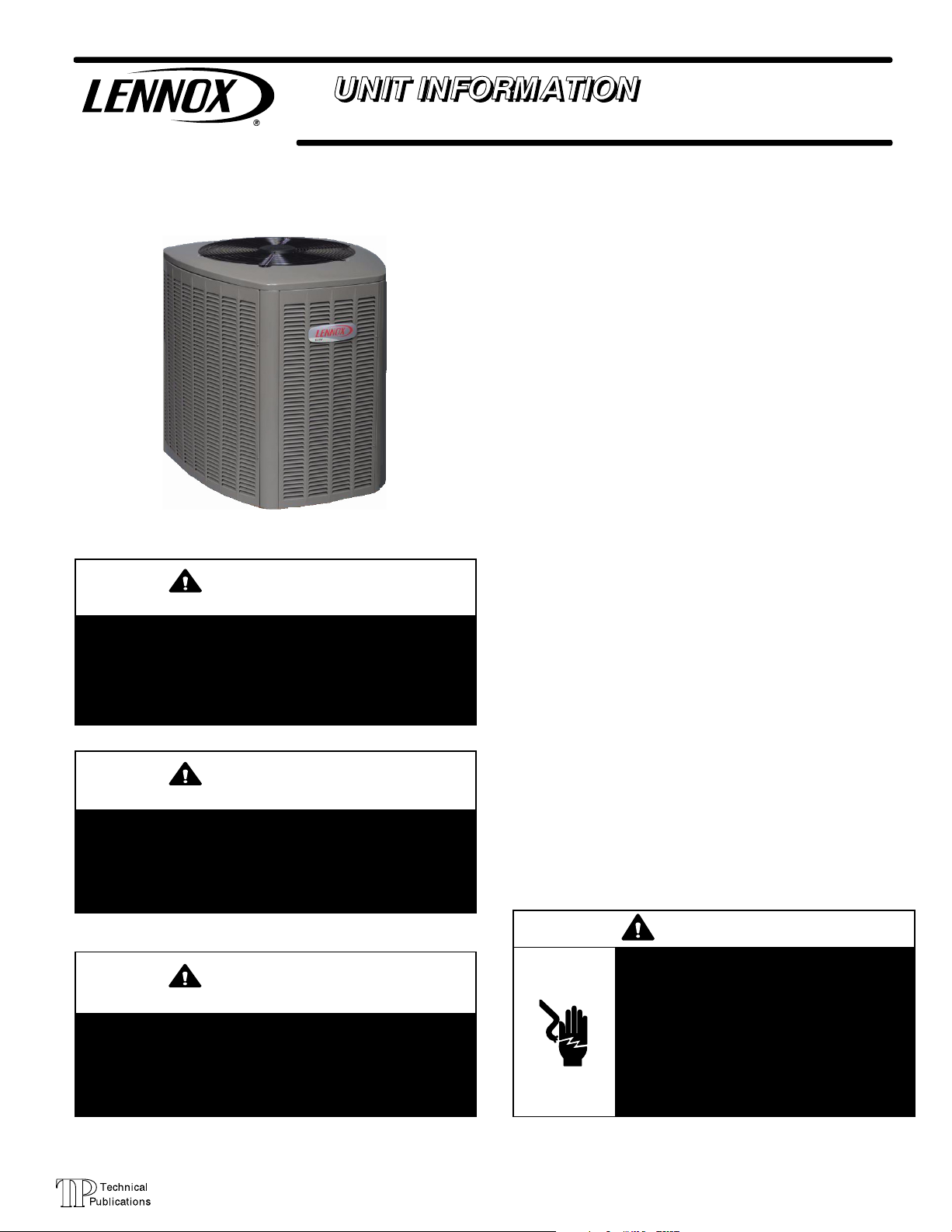
XP16 (HFC−410A) SERIES UNITS
WARNING
Improper installation, adjustment, alteration, service or
maintenance can cause personal injury, loss of life, or
damage to property.
Installation and service must be performed by a licensed
professional installer (or equivalent) or a service agency.
CAUTION
Physical contact with metal edges and corners while
applying excessive force or rapid motion can result in
personal injury. Be aware of, and use caution when
working near these areas during installation or while
servicing this equipment.
XP16
TABLE OF CONTENTS
Model Number Identification 2. . . . . . . . . . . . . . . . . . . .
Typical Serial Number Identification 2. . . . . . . . . . . . . .
Specifications 2. . . . . . . . . . . . . . . . . . . . . . . . . . . . . . . . .
Electrical Data 3. . . . . . . . . . . . . . . . . . . . . . . . . . . . . . . .
Unit Dimensions 4. . . . . . . . . . . . . . . . . . . . . . . . . . . . . .
Unit Parts Arrangement 5. . . . . . . . . . . . . . . . . . . . . . . .
Operating Gauge Set and Service Valves 7. . . . . . . . .
Recovering Refrigerant from System 9. . . . . . . . . . . . .
Unit Placement 10. . . . . . . . . . . . . . . . . . . . . . . . . . . . . . .
Removing and Installing Panels 12. . . . . . . . . . . . . . . . .
New or Replacement Line Set 14. . . . . . . . . . . . . . . . . .
Brazing Connections 16. . . . . . . . . . . . . . . . . . . . . . . . . . .
Flushing Line Set and Indoor Coil 19. . . . . . . . . . . . . . .
Installing Indoor Metering Device 20. . . . . . . . . . . . . . . .
Leak Test Line Set and Indoor Coil 21. . . . . . . . . . . . . .
Evacuating Line Set and Indoor Coil 22. . . . . . . . . . . . .
Electrical 23. . . . . . . . . . . . . . . . . . . . . . . . . . . . . . . . . . . . .
Servicing Units Void of Charge 24. . . . . . . . . . . . . . . . . .
Unit Start−Up 24. . . . . . . . . . . . . . . . . . . . . . . . . . . . . . . . . .
System Refrigerant 24. . . . . . . . . . . . . . . . . . . . . . . . . . . .
System Operation 36. . . . . . . . . . . . . . . . . . . . . . . . . . . . .
Defrost System 37. . . . . . . . . . . . . . . . . . . . . . . . . . . . . . .
Maintenance 44. . . . . . . . . . . . . . . . . . . . . . . . . . . . . . . . . .
Unit Wiring Diagram and Sequence of
Operations 46. . . . . . . . . . . . . . . . . . . . . . . . . . . . . . . . . . . . .
Checklists 51. . . . . . . . . . . . . . . . . . . . . . . . . . . . . . . . . . . .
The XP16 is a high efficiency residential split−system
two−stage heat pump unit, which features a scroll
compressor and HFC−410A refrigerant. XP16 units are
available in 2, 3, 4 and 5 tons. tons. XP16 units are rated for
230 volts only. Applications where supply voltage is less
requires a hard start kit. The series is designed for use with
an indoor unit with an expansion valve approved for
HFC−410A.
IMPORTANT
The Clean Air Act of 1990 bans the intentional venting of
refrigerant (CFCs, HCFCs and HFCs) as of July 1, 1992.
Approved methods of recovery, recycling or reclaiming
must be followed. Fines and/or incarceration may be
levied for noncompliance.
Page 1
WARNING
Electric Shock Hazard. Can cause injury or
death. Unit must be grounded in
accordance with national and local codes.
Line voltage is present at all components
when unit is not in operation on units with
single-pole contactors. Disconnect all
remote electric power supplies before
opening access panel. Unit may have
multiple power supplies.
2006 Lennox Industries Inc.
Page 2
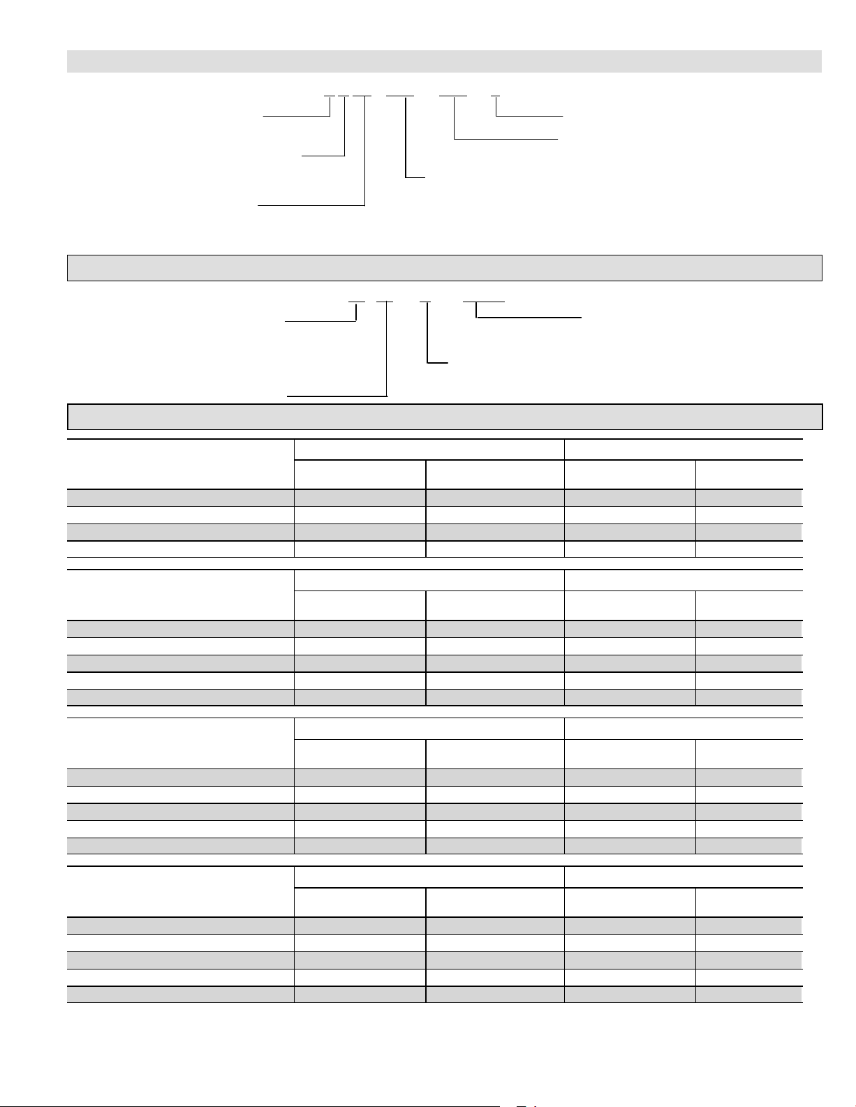
Model Number Identification
Refrigerant Type
X = HFC−410A
Unit Type
P = Heat Pump
− −
P 16 036
X 5
Nominal Cooling Capacity
230
−
Minor Revision Number
Voltage
230 = 208/230V−1ph−60hz
024 = 2 tons
Series
036 = 3 tons
048 = 4 tons
060 = 5 tons
Typical Serial Number Identification
Location Code
19 = Saltillo, Mexico
58 = Marshalltown, IA
Year Code
08 = 2008
09 = 2009
10 = 2010
19 09 C
05716
5 (or 6) Digit Unique Number
Month Code
A = January
B = February
C = March
Specifications
Unit Outdoor Fan
Model Number
XP16−024−230−01 74 9 lbs. 9 oz. 3 18
XP16−024−230−03 74 7 lbs. 13 oz. 3 18
XP16−024−230−04 74 7 lbs. 13 oz. 3 18
XP16−024−230−05 74 8 lbs. 13 oz. 3 18
Sound Rating Number
(dB)
1
Factory Refrigerant
Charge
2
Number of Blades Diameter − inches.
Unit Outdoor Fan
Model Number
XP16−036−230−01 76 12 lbs. 8 oz. 4 22
XP16−036−230−02 76 12 lbs. 8 oz. 4 22
XP16−036−230−03 76 10 lbs. 4 oz. 4 22
XP16−036−230−04 76 10 lbs. 4 oz. 4 22
XP16−036−230−05 76 10 lbs. 9 oz. 4 22
Model Number
XP16−048−230−01 76 15 lbs. 7 oz. 4 22
XP16−048−230−02 76 15 lbs. 7 oz. 4 22
XP16−048−230−03 76 15 lbs. 7 oz. 4 22
XP16−048−230−04 76 15 lbs. 7 oz. 4 22
XP16−048−230−05 76 11 lbs. 12 oz. 3 26
Model Number
XP16−060−230−01 78 13 lbs. 8 oz. 3 26
XP16−060−230−02 78 13 lbs. 8 oz. 3 26
XP16−060−230−03 78 11 lbs. 7 oz. 3 26
XP16−060−230−04 78 11 lbs. 7 oz. 3 26
XP16−060−230−05 78 12 lbs. 15 oz. 3 26
1
Tested according to AHRI Standard 270−2008 test conditions.
2
Refrigerant charge sufficient for 15 feet length of refrigerant lines.
Sound Rating Number
Sound Rating Number
Sound Rating Number
(dB)
(dB)
(dB)
1
1
1
Factory Refrigerant
Unit Outdoor Fan
Factory Refrigerant
Unit Outdoor Fan
Factory Refrigerant
Charge
Charge
Charge
2
2
2
Number of Blades Diameter − inches.
Number of Blades Diameter − inches.
Number of Blades Diameter − inches.
Page 2
XP16
Page 3
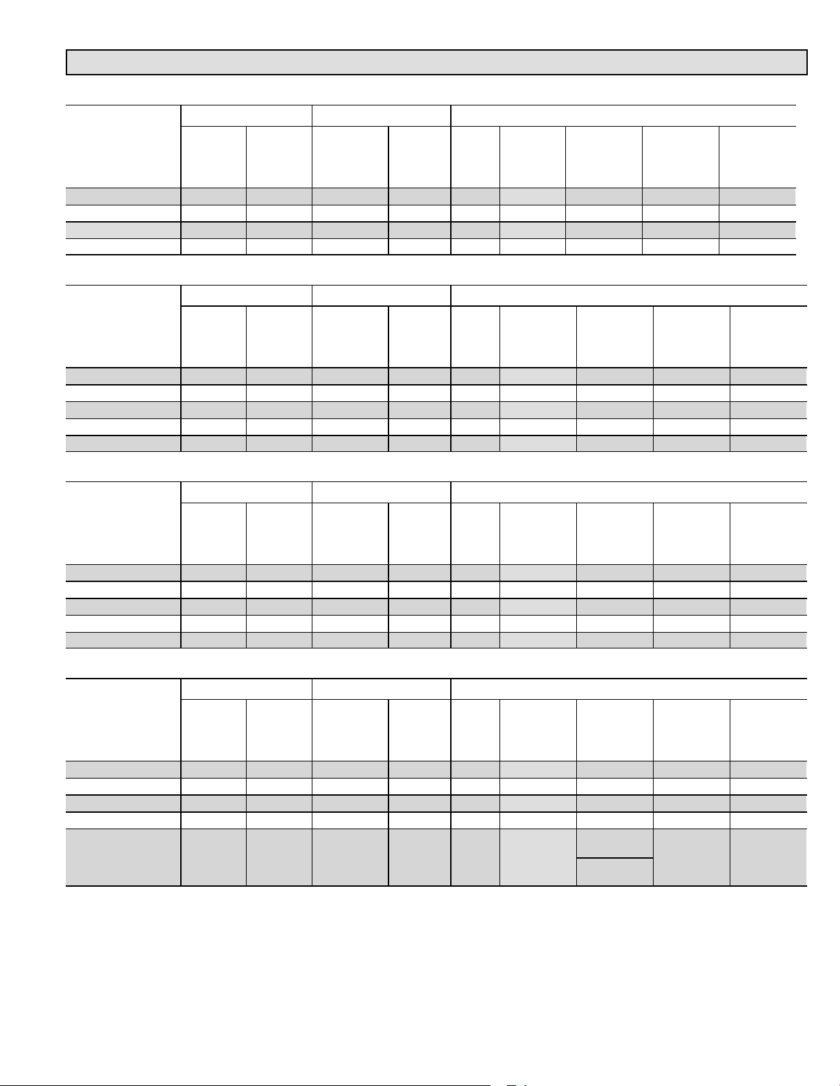
Electrical Data
208/230V−60 Hz−1 Ph
Unit Compressor Condenser Fan
Model Number
Over−
current
Protection
(amps)
1
Minimum
Circuity
Ampacity
Rated Load
Amps (RLA)
2
Maximum
XP16−024−230−01 20 14.0 10.25 52.0 1/10 PSC 1075 0.7 1.4
XP16−024−230−03 20 14.0 10.25 52.0 1/10 PSC 1075 0.7 1.4
XP16−024−230−04 20 14.0 10.25 52.0 1/10 PSC 1075 0.7 1.4
XP16−024−230−05 20 14.0 10.25 52.0 1/10 PSC 1075 0.7 1.4
Unit Compressor Condenser Fan
Model Number
Over−
current
Protection
(amps)
1
Minimum
Circuity
Ampacity
Rated Load
Amps (RLA)
2
Maximum
XP16−036−230−01 35 22.0 16.67 82.0 1/6 PSC 825 1.1 2.1
XP16−036−230−02 35 22.0 16.67 82.0 1/6 PSC 825 1.1 2.1
XP16−036−230−03 35 22.0 16.67 82.0 1/6 PSC 825 1.1 2.1
XP16−036−230−04 35 22.0 16.67 82.0 1/6 PSC 825 1.1 1.87
XP16−036−230−05 35 22.5 16.67 82.0 1/4 PSC 825 1.7 3.1
Locked
Rotor
Amps
(LRA)
Motor
HP
208/230V−60 Hz−1 Ph
Locked
Rotor
Amps
(LRA)
Motor
HP
Motor
Type
Motor Type
Nominal
RPM
Nominal
RPM
Full Load
Amps (FLA)
Full Load
Amps (FLA)
Locked Rotor
Amps (LRA)
Locked Rotor
Amps (LRA)
208/230V−60 Hz−1 Ph
Unit Compressor Condenser Fan
Model Number
Maximum
Over−
current
Protection
(amps)
1
Minimum
Circuity
Ampacity
Rated Load
Amps (RLA)
2
Locked
Rotor
Amps
(LRA)
Motor
HP
Motor Type
Nominal
RPM
Full Load
Amps (FLA)
Locked Rotor
Amps (LRA)
XP16−048−230−01 45 28.2 21.15 96.0 1/4 PSC 825 1.7 3.1
XP16−048−230−02 45 28.2 21.15 96.0 1/4 PSC 825 1.7 3.1
XP16−048−230−03 45 28.2 21.15 96.0 1/4 PSC 825 1.7 3.1
XP16−048−230−04 45 28.2 21.15 96.0 1/4 PSC 825 1.7 3.1
XP16−048−230−05 45 28.2 21.15 96.0 1/3 PSC 825 1.8 2.9
208/230V−60 Hz−1 Ph
Unit Compressor Condenser Fan
Model Number
Maximum
Over−
current
Protection
(amps)
1
Minimum
Circuity
Ampacity
Rated Load
Amps (RLA)
2
Locked
Rotor
Amps
(LRA)
Motor
HP
Motor Type
Nominal
3
RPM
Full Load
Amps (FLA)
Locked Rotor
Amps (LRA)
XP16−060−230−01 55 33.9 25.64 118.0 1/3 PSC 825 1.8 2.9
XP16−060−230−02 60 33.9 25.87 118.0 1/3 PSC 825 1.8 2.9
XP16−060−230−03 60 33.9 25.87 118.0 1/3 PSC 825 1.8 2.9
XP16−060−230−04 60 33.9 25.87 118.0 1/3 PSC 825 1.8 2.9
700
XP16−060−230−05 60 35.1 25.87 118.0 1/3 VS
1
HACR type circuit breaker or fuse.
2
Refer to National or Canadian Electrical Code manual to determine wire, fuse and disconnect size requirements.
3
PSC = permanent split capacitor motor (single speed); VS = variable speed.
(1st Stage)
820
(2nd Stage)
2.8 N/A
XP16
Page 3
Page 4
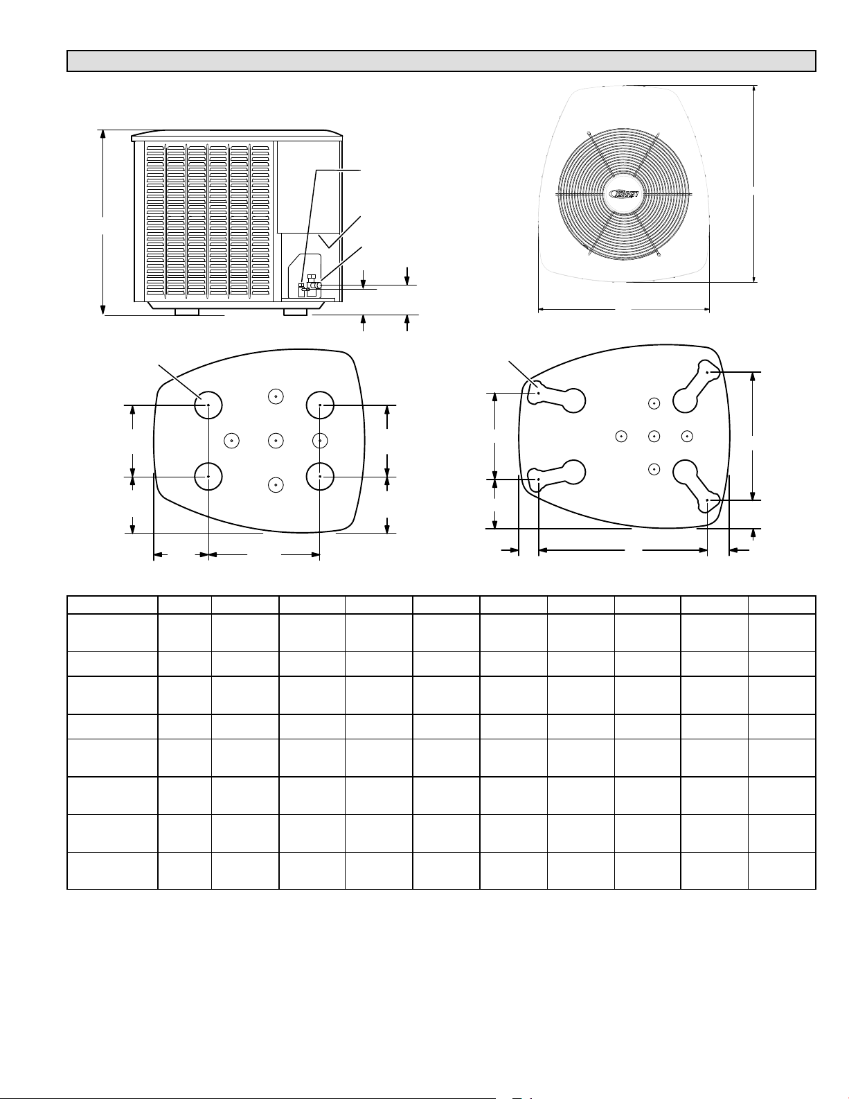
Unit Dimensions − Inches (mm)
A
LIQUID LINE
CONNECTION
ELECTRICAL INLETS
SUCTION LINE
CONNECTION
C
9−1/2
(241)
8−1/4
(210)
4−3/4"
(121)
UNIT SUPPORT FEET
B
TOP VIEW
D
E
F
G
XP16−036 to −060 BASE WITH LEGS
K
J
H
UNIT SUPPORT
FEET
8−1/2
(216)
8−3/4
(222)
SIDE VIEW
5−1/2
(140)
13−1/2
(343)
XP16−024 BASE SECTION
4−1/2"
(108)
Model Number A B C D E F G H J K
XP16−024−01,
−02, −03, −04
31 (889) 27 (686) 28 (711) − − − − − − −
XP16−024−05 35 (889) 27 (686) 28 (711) − − − − − − −
XP16−036−01,
−02, −03, −04
35 (889) 30−1/2 (775) 35 (889) 13−7/8 (352) 7−3/4 (197) 3−1/4 (83) 27−1/8 (689) 3−5/8 (92) 4−1/2 (114) 20−5/8 (524)
XP16−036−05 39 (991) 30−1/2 (775) 35 (889) 13−7/8 (352) 7−3/4 (197) 3−1/4 (83) 27−1/8 (689) 3−5/8 (92) 4−1/2 (114) 20−5/8 (524)
XP16−048−01,
−02, −03, −04
XP16−048−05 35 (889) 35−1/2 (902)
XP16−060−01,
−02, −03, −04
XP16−060−05 45 (1143 35−1/2 (902)
45 (1143) 30−1/2 (775) 35 (889)) 16−7/8 (429) 8−3/4 (222) 3−1/8 (79) 30−3/4 (781) 4−5/8 (117) 3−3/4 (95) 26−7/8 (683)
39 (991) 35−1/2 (902)
39−1/2
(1003)
39−1/2
(1003)
39−1/2
(1003)
16−7/8 (429) 8−3/4 (222) 3−1/8 (79) 30−3/4 (781) 4−5/8 (117) 3−3/4 (95) 26−7/8 (683)
16−7/8 (429) 8−3/4 (222) 3−1/8 (79) 30−3/4 (781) 4−5/8 (117) 3−3/4 (95) 26−7/8 (683)
16−7/8 (429) 8−3/4 (222) 3−1/8 (79) 30−3/4 (781) 4−5/8 (117) 3−3/4 (95) 26−7/8 (683)
Page 4
XP16
Page 5
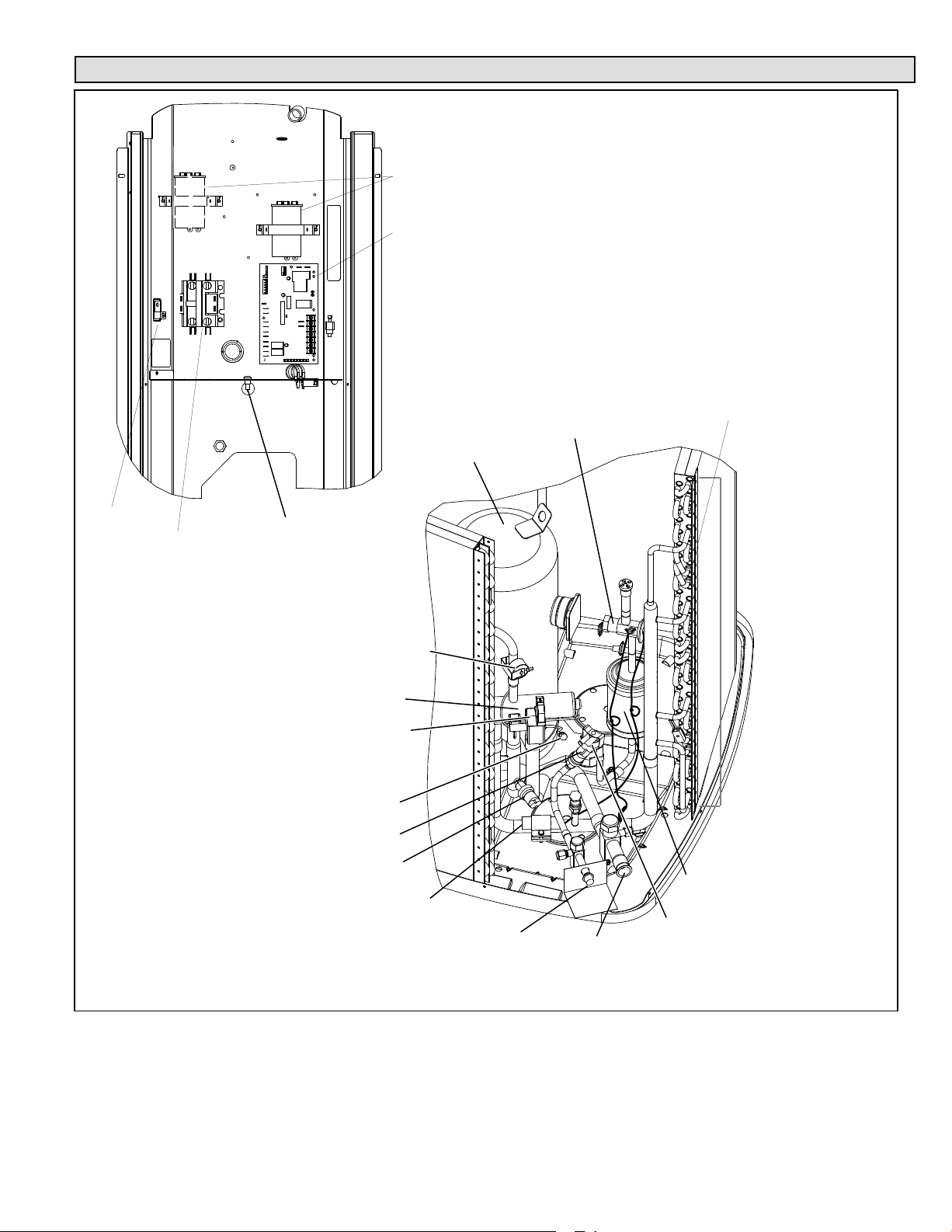
Typical Unit Parts Arrangement
CAPACITOR (LOCATION OF
CAPACITOR VARIES.)
DEFROST CONTROL (A108)
GROUND
LUG
CONTACTOR
(K−1)
AMBIENT
TEMPERATURE
SENSOR (RT13)
DISCHARGE LINE SENSOR (RT28)
REVERSING VALVE
REVERSING VALVE SOLENOID
TRUE SUCTION PORT
HIGH PRESSURE SWITCH (S4)
COMPRESSOR
CHECK
EXPANSION VALVE
FOR COIL SENSOR (RT21) LOCATION
SEE FIGURE 2.
XP16
LOW PRESSURE SWITCH (S87)
EXPANSION VALVE SENSING BULB
LIQUID VALVE AND GAUGE PORT / LIQUID LINE CONNECTIONS
Figure 1. Typical Parts Arrangements
Page 5
CRANKCASE HEATER THERMOSTAT (S40)
VAPOR VALVE AND GAUGE
PORT / SUCTION LINE
CONNECTIONS
LIQUID LINE BI−FLOW FILTER DRIER
Page 6
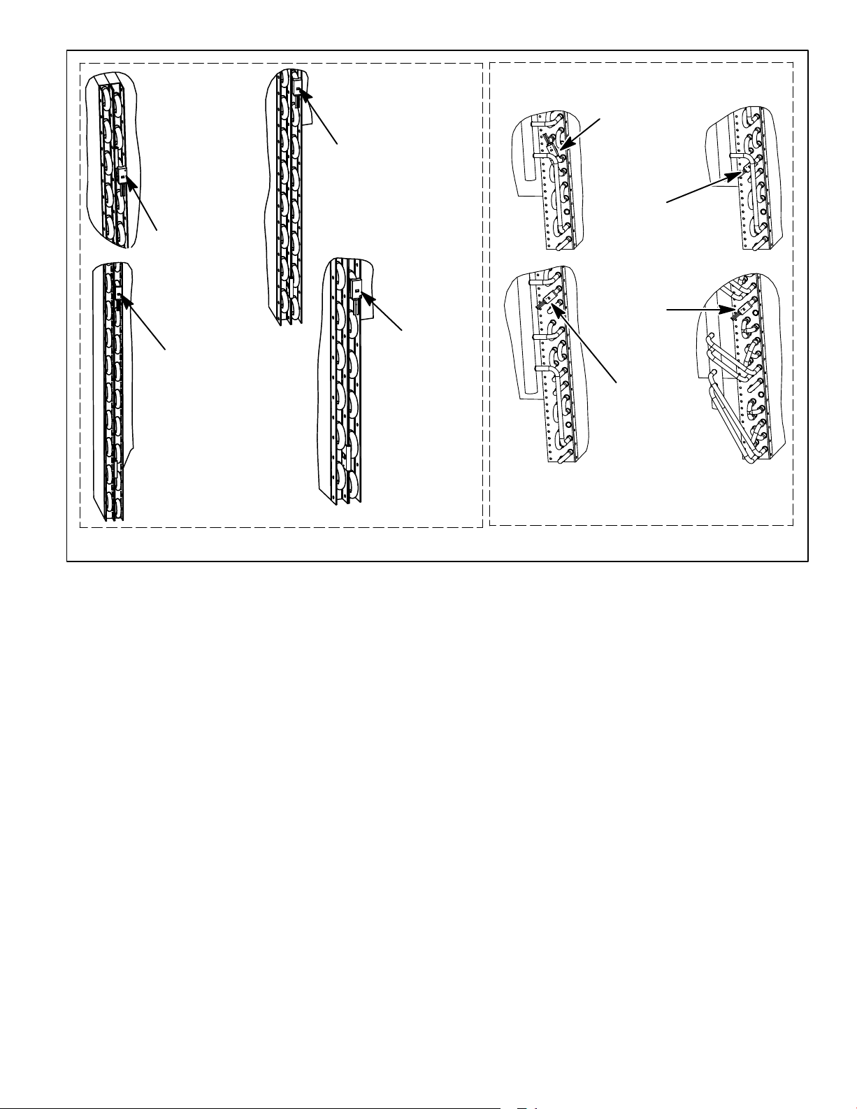
XP16−024
COIL SENSOR −THIRD
HAIRPIN DOWN FROM
THE TOP ON INSIDE
ROW.
XP16−036
COIL SENSOR − NINTH
HAIRPIN UP FROM THE
BOTTOM ON INSIDE
ROW.
XP16−048
COIL SENSOR − EIGHT HAIRPIN
UP FROM THE BOTTOM ON
INSIDE ROW.
XP16−060
COIL SENSOR −
SIXTH HAIRPIN UP
FROM THE BOTTOM
ON INSIDE ROW.
XP16−024
COIL SENSOR
7 tubes up from
bottom (7−1/2")
XP16−036
COIL SENSOR
17 tubes up
from bottom
(17−1/2")
XP16−060
COIL SENSOR
12 tubes up from
bottom (11−1/2")
XP16−048
COIL SENSOR
13 tubes up from
bottom (12−1/2")
(XP16−XXX−230−05)
(XP16−XXX−230−01 through 04)
CLIP COIL TEMPERATURE SENSOR FROM THE DEFROST BOARD ON THE RETURN BEND SHOWN.
Figure 2. Coil Sensor (RT21) Locations
Page 6
XP16
Page 7
WARNING
IMPORTANT
This product and/or the indoor unit it is matched with may
contain fiberglass wool.
Disturbing the insulation during installation, maintenance,
or repair will expose you to fiberglass wool dust. Breathing
this may cause lung cancer. (Fiberglass wool is known to
the State of California to cause cancer.)
Fiberglass wool may also cause respiratory, skin, and eye
irritation.
To reduce exposure to this substance or for further
information, consult material safety data sheets available
from address shown below, or contact your supervisor.
Lennox Industries Inc.
P.O. Box 799900
Dallas, TX 75379−9900
Operating Gauge Set and Service Valves
These instructions are intended as a general guide and do
not supersede local codes in any way. Consult authorities
who have jurisdiction before installation.
TORQUE REQUIREMENTS
When servicing or repairing heating, ventilating, and air
conditioning components, ensure the fasteners are
appropriately tightened. Table 1 lists torque values for
fasteners.
IMPORTANT
Only use Allen wrenches of sufficient hardness (50Rc −
Rockwell Harness Scale minimum). Fully insert the
wrench into the valve stem recess.
Service valve stems are factory−torqued (from 9 ft−lbs for
small valves, to 25 ft−lbs for large valves) to prevent
refrigerant loss during shipping and handling. Using an
Allen wrench rated at less than 50Rc risks rounding or
breaking off the wrench, or stripping the valve stem
recess.
See the Lennox Service and Application Notes #C−08−1 for
further details and information.
To prevent stripping of the various caps used, the
appropriately sized wrench should be used and fitted
snugly over the cap before tightening.
Table 1. Torque Requirements
Parts Recommended Torque
Service valve cap 8 ft.− lb. 11 NM
Sheet metal screws 16 in.− lb. 2 NM
Machine screws #10 28 in.− lb. 3 NM
Compressor bolts 90 in.− lb. 10 NM
Gauge port seal cap 8 ft.− lb. 11 NM
USING MANIFOLD GAUGE SET
When checking the system charge, only use a manifold
gauge set that features low loss anti−blow back fittings.
Manifold gauge set used with HFC−410A refrigerant
systems must be capable of handling the higher system
operating pressures. The gauges should be rated for use
with pressures of 0 − 800 psig on the high side and a low side
of 30" vacuum to 250 psig with dampened speed to 500 psi.
Gauge hoses must be rated for use at up to 800 psig of
pressure with a 4000 psig burst rating.
OPERATING SERVICE VALVES
The liquid and vapor line service valves are used for
removing refrigerant, flushing, leak testing, evacuating,
checking charge and charging.
Each valve is equipped with a service port which has a
factory−installed valve stem. Figure 3 provides information
on how to access and operating both angle and ball service
valves.
XP16
Page 7
Page 8
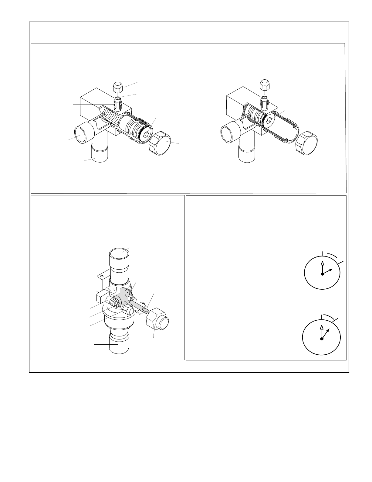
SERVICE VALVES
ANGLE AND BALL
Operating Angle Type Service Valve:
1. Remove stem cap with an appropriately sized wrench.
2. Use a service wrench with a hex−head extension (3/16" for liquid line valve sizes and 5/16" for vapor line valve sizes) to back
the stem out counterclockwise as far as it will go.
SERVICE PORT CAP
SERVICE PORT CORE
(VALVE STEM SHOWN
TO INDOOR
UNIT
(VALVE STEM SHOWN OPEN)
INSERT HEX WRENCH HERE
CLOSED) INSERT HEX
WRENCH HERE
SERVICE PORT
CORE
TO OUTDOOR UNIT
ANGLE−TYPE SERVICE VALVE
(BACK−SEATED OPENED)
When service valve is OPEN, the service port is
open to linE set, indoor and outdoor unit.
Operating Ball Type Service Valve:
1. Remove stem cap with an appropriately sized wrench.
2. Use an appropriately sized wrenched to open. To open valve,
roate stem counterclockwise 90°. To close rotate stem clockwise 90°.
TO INDOOR UNIT
TO OPEN ROTATE STEM
COUNTERCLOCKWISE 90°.
TO CLOSE ROTATE STEM
CLOCKWISE 90°.
SERVICE PORT
SERVICE PORT
SERVICE PORT
CORE
CAP
TO OUTDOOR
UNIT
BALL (SHOWN
CLOSED)
VALV E
STEM
STEM CAP
STEM CAP
ANGLE−TYPE SERVICE VALVE
(FRONT−SEATED CLOSED)
WHEN SERVICE VALV E IS CLOSED, THE SERVICE PORT IS
OPEN
TO THE LINE SET AND INDOOR UNIT.
To Access Service Port:
A service port cap protects the service port core from contamination and
serves as the primary leak seal.
1. Remove service port cap with an appropriately sized wrench.
2. Connect gauge set to service port.
3. When testing is completed, replace service port cap and tighten as
follows:
D With torque wrench: Finger tighten and
torque cap per table 1.
D Without torque wrench: Finger tighten and
use an appropriately sized wrench to turn
an additional 1/6 turn clockwise.
Reinstall Stem Cap:
Stem cap protects the valve stem from damage and serves as the
primary seal. Replace the stem cap and tighten as follows:
D With Torque Wrench: Finger tighten and
then torque cap per table 1.
D Without Torque Wrench: Finger
tighten and use an appropriately
sized wrench to turn an additional
1/12 turn clockwise.
9
10
9
10
8
12
11
8
7
6
12
11
7
6
1/6 TURN
1
2
3
4
5
1/12 TURN
1
2
3
4
5
NOTE A label with specific torque requirements may be affixed to the stem cap. If the label is present, use the specified torque.
Figure 3. Angle and Ball Service Valves
Page 8
XP16
Page 9
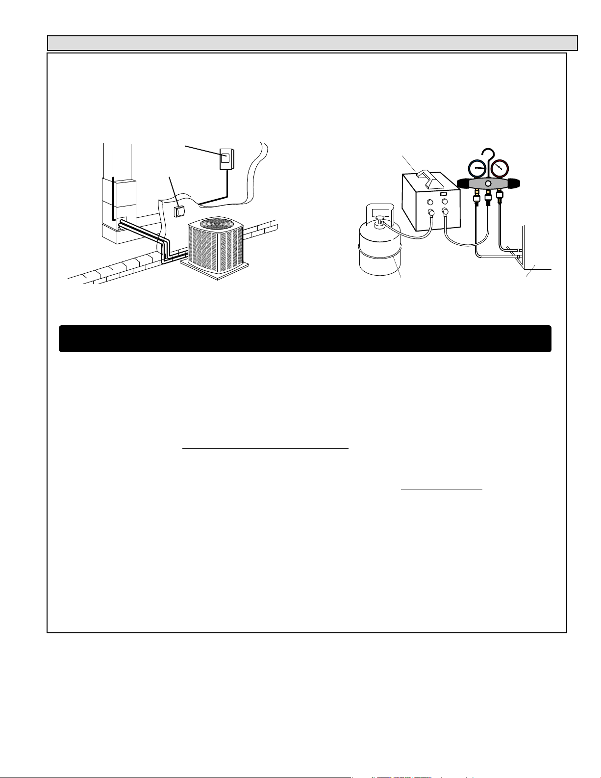
Recovering Refrigerant from System
DISCONNECT POWER
Disconnect all power to the existing outdoor unit at the disconnect
1
switch or main fuse box/breaker panel.
MAIN FUSE BOX/BREAKER PANEL
MAIN FUSE
BOX/BREAKER
PANEL
DISCONNECT
SWITCH
RECOVERING REFRIGERANT
Remove existing HCFC−22 refrigerant using one of the following procedures:
3
IMPORTANT Some system configurations may contain higher than normal refrigerant charge due to either large internal coil vol-
umes, and/or long line sets.
CONNECT MANIFOLD GAUGE SET
Connect a gauge set, clean recovery cylinder and a recovery
2
machine to the service ports of the existing unit. Use the
instructions provided with the recovery machine to make the
connections.
MANIFOLD GAUGES
RECOVERY MACHINE
LOW
CLEAN RECOVERY
CYLINDER
OUTDOOR UNIT
HIGH
METHOD 1:
Us this method if the existing outdoor unit is not equipped with shut−off valves, or if the unit is not operational and you plan to use the existing
HCFC−22 to flush the system.
Remove all HCFC−22 refrigerant from the existing system. Check gauges after shutdown to confirm that the entire system is completely void of
refrigerant.
METHOD 2:
Use this method if the existing outdoor unit is equipped with manual shut−off valves, and you plan to use new HCFC−22 refrigerant to flush the
system.
The following devices could prevent full system charge recovery into the outdoor unit
D Outdoor unit’s high or low−pressure switches (if applicable) when tripped can cycle the compressor OFF.
D Compressor can stop pumping due to tripped internal pressure relief valve.
D Compressor has internal vacuum protection that is designed to unload the scrolls (compressor stops pumping) when the pressure ratio meets
a certain value or when the suction pressure is as high as 20 psig. (Compressor suction pressures should never be allowed
Prolonged operation at low suction pressures will result in overheating of the scrolls and permanent damage to the scroll tips, drive bearings
and internal seals.)
Once the compressor can not pump down to a lower pressure due to one of the above system conditions, shut off the vapor valve. Turn OFF the
main power to unit and use a recovery machine to recover any refrigerant left in the indoor coil and line set.
Perform the following task:
A Start the existing HCFC−22 system in the cooling mode and close the liquid line valve.
B Use the compressor to pump as much of the existing HCFC−22 refrigerant into the outdoor unit until the outdoor system is full. Turn the outdoor
unit main power OFF and use a recovery machine to remove the remaining refrigerant from the system.
NOTE It may be necessary to bypass the low pressure switches (if equipped) to ensure complete refrigerant evacuation.
C When the low side system pressures reach 0 psig, close the vapor line valve.
D Check gauges after shutdown to confirm that the valves are not allowing refrigerant to flow back into the low side of the system.
:
to go into a vacuum.
Figure 4. Refrigerant Recovery
XP16
Page 9
Page 10
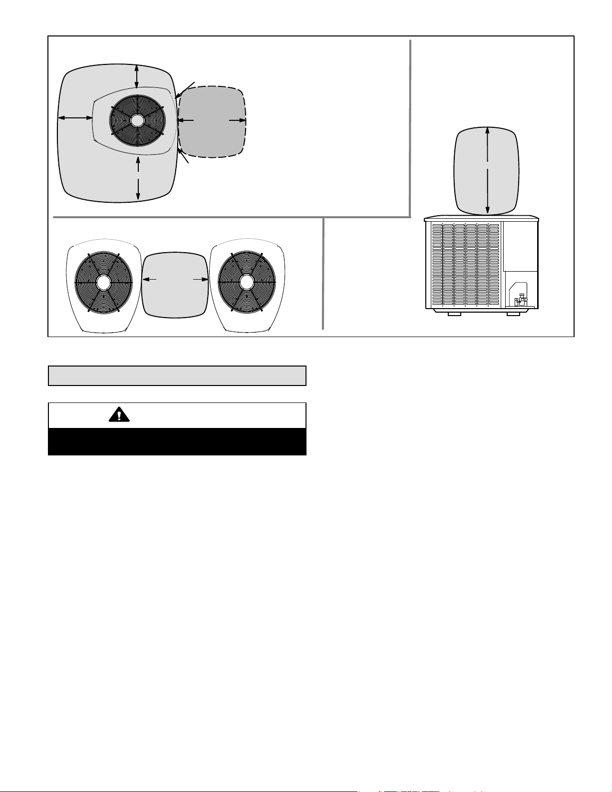
CLEARANCE ON ALL SIDES INCHES (MILLIMETERS)
12 (305)
6 (152)
36 (914)
ACCESS PANEL
CONTROL PANEL
ACCESS
LOCATION
30 (762)
LINE SET
CONNECTIONS
MINIMUM CLEARANCE BETWEEN
TWO UNITS
24 (610)
Figure 5. Installation Clearances
NOTES:
D Clearance to one of the other three
sides must be 36 inches (914mm).
D Clearance to one of the remaining
two sides may be 12 inches
(305mm) and the final side may be
6 inches (152mm).
MINIMUM CLEARANCE
ABOVE UNIT
48 (1219)
Unit Placement
CAUTION
In order to avoid injury, take proper precaution when lifting
heavy objects.
See Unit Dimensions on page 3 for sizing mounting slab,
platforms or supports. Refer to figure 5 for mandatory
installation clearance requirements.
POSITIONING CONSIDERATIONS
Consider the following when positioning the unit:
D Some localities are adopting sound ordinances based
on the unit’s sound level registered from the adjacent
property, not from the installation property. Install the
unit as far as possible from the property line.
D When possible, do not install the unit directly outside a
window. Glass has a very high level of sound
transmission. For proper placement of unit in relation to
a window see the provided illustration in figure 6, detail
A.
PLACING UNIT ON SLAB
When installing unit at grade level, the top of the slab should
be high enough above grade so that water from higher
ground will not collect around the unit. The slab should have
a slope tolerance as described in figure 6, detail B.
NOTE If necessary for stability, anchor unit to slab as
described in figure 6, detail D.
ELEVATING THE UNIT
Units are outfitted with elongated support feet as illustrated
in figure 6, detail C.
If additional elevation is necessary, raise the unit by
extending the height of the unit support feet. This may be
achieved by using a 2 inch (50.8mm) Schedule 40 female
threaded adapter.
The specified coupling will fit snuggly into the recessed
portion of the feet. Use additional 2 inch (50.8mm) Schedule
40 male threaded adaptors which can be threaded into the
female threaded adaptors to make additional adjustments to
the level of the unit.
NOTE Keep the height of extenders short enough to
ensure a sturdy installation. If it is necessary to extend
further, consider a different type of field−fabricated
framework that is sturdy enough for greater heights.
Page 10
XP16
Page 11
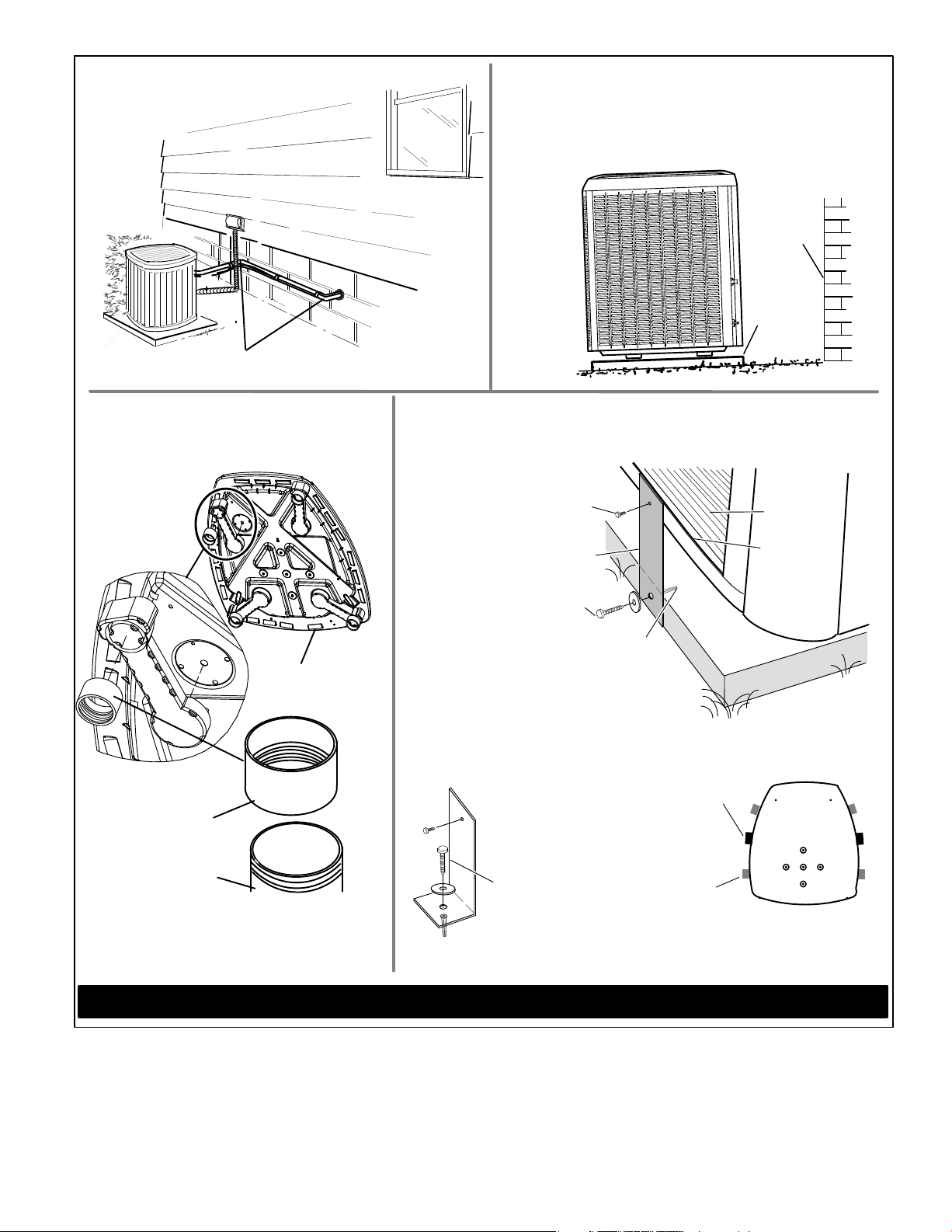
DETAIL A
Install unit away from windows.
Outside Unit Placement
DETAIL B
Install unit level or, if on a slope, maintain slope tolerance of two
(2) degrees (or two inches per five feet [50 mm per 1.5 m]) away
from building structure.
Slab Mounting at Ground Level
BUILDING
STRUCTURE
MOUNTING
SLAB
TWO 90° ELBOWS INSTALLED IN LINE SET WILL
REDUCE LINE SET VIBRATION.
DETAIL C
Elevated Slab Mounting
using Feet Extenders
LEG DETAIL
2" (50.8MM) SCH 40
FEMALE THREADED
ADAPTER
BASE
GROUND LEVEL
STABILIZING UNIT ON UNEVEN SURFACES
DETAIL D
#10 1/2" LONG SELF−DRILLING
SHEET METAL SCREWS
STABILIZING BRACKET (18 GAUGE
METAL 2" WIDTH; HEIGHT AS
#10 1−1/4" LONG HEX HD SCREW
Concrete slab use two plastic anchors (hole
drill 1/4")
Wood or plastic slab no plastic anchor (hole
drill 1/8")
DETAIL E
Stabilizing bracket (18 gauge metal 2" (50.8mm) width; height as required); bend to form
right angle as exampled below.
Slab Side Mounting
REQUIRED)
AND FLAT WASHER
Deck Top Mounting
MINIMUM ONE
PER SIDE
COIL
BASE PAN
CORNER POST
2" (50.8MM) SCH 40
MALE THREADED
ADAPTER
Use additional 2" SCH 40 male threaded adapters
which can be threaded into the female threaded
adapters to make additional adjustments to the level
of the unit.
IMPORTANT To help stabilize an outdoor unit, some installations may require strapping the unit to the pad using brackets and anchors
commonly available in the marketplace.
One bracket per side (minimum). For extra stability, two brackets per side, two inches
(51mm) from each corner.
SAME FASTENERS AS
SLAB SIDE MOUNTING.
FOR EXTRA
STABILITY
Figure 6. Placement, Slab Mounting and Stabilizing Unit
XP16
Page 11
Page 12
STABILIZING UNIT ON UNEVEN SURFACES
IMPORTANT
Unit Stabilizer Bracket Use (field−provided):
Always use stabilizers when unit is raised above the
factory height. (Elevated units could become unstable in
gusty wind conditions).
Stabilizers may be used on factory height units when
mounted on unstable an uneven surface.
With unit positioned at installation site, perform the
following
1. Remove two side louvered panels to expose the unit
2. Install the brackets as illustrated in figure 6, detail D or
3. Replace the panels after installation is complete.
ROOF MOUNTING
Install the unit a minimum of 6 inches (152 mm) above the
roof surface to avoid ice build−up around the unit. Locate the
unit above a load bearing wall or area of the roof that can
adequately support the unit. Consult local codes for rooftop
applications.
If unit coil cannot be mounted away from prevailing winter
winds, a wind barrier should be constructed. Size barrier at
least the same height and width as outdoor unit. Mount
barrier 24 inches (610 mm) from the sides of the unit in the
direction of prevailing winds.
:
base.
E using conventional practices.
Removing and Installing Panels
IMPORTANT
Do not allow panels to hang on unit by top tab. Tab is for
alignment and not designed to support weight of panel.
IMPORTANT
To help stabilize an outdoor unit, some installations may
require strapping the unit to the pad using brackets and
anchors commonly available in the marketplace.
WARNING
To prevent personal injury, or damage to panels, unit or
structure, be sure to observe the following:
While installing or servicing this unit, carefully stow all
removed panels out of the way, so that the panels will not
cause injury to personnel, nor cause damage to objects or
structures nearby, nor will the panels be subjected to
damage (e.g., being bent or scratched).
While handling or stowing the panels, consider any
weather conditions, especially windy conditions, that may
cause panels to be blown around and battered.
NOTICE
Roof Damage!
This system contains both refrigerant and oil. Some
rubber roofing material may absorb oil and cause the
rubber to swell when it comes into contact with oil. The
rubber will then bubble and could cause leaks. Protect the
roof surface to avoid exposure to refrigerant and oil
during service and installation. Failure to follow this
notice could result in damage to roof surface.
Page 12
XP16
Page 13
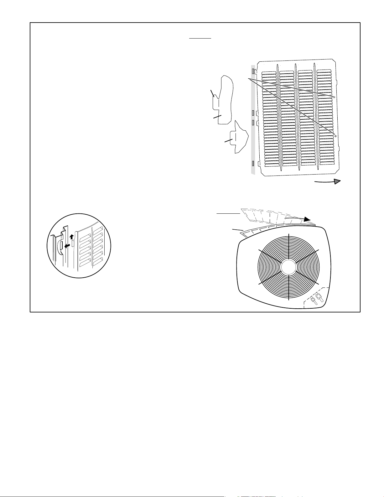
LOUVERED PANEL REMOVAL
Remove the louvered panels as follows:
1. Remove two screws, allowing the panel to swing open
slightly.
2. Hold the panel firmly throughout this procedure. Rotate bot-
tom corner of panel away from hinged corner post until lower three tabs clear the slots as illustrated in detail B.
3. Move panel down until lip of upper tab clears the top slot in
corner post as illustrated in detail A.
LOUVERED PANEL INSTALLATION
Position the panel almost parallel with the unit as illustrated
in detail D with the screw side as close to the unit as possible. Then, in a continuous motion:
1. Slightly rotate and guide the lip of top tab inward as illustrated in detail A and C; then upward into the top
slot of the hinge corner post.
2. Rotate panel to vertical to fully engage all tabs.
3. Holding the panel’s hinged side firmly in place, close
the right−hand side of the panel, aligning the screw
holes.
4. When panel is correctly positioned and aligned, insert
the screws and tighten.
Detail C
MAINTAIN MINIMUM PANEL ANGLE (AS CLOSE TO PARALLEL WITH THE UNIT
AS POSSIBLE) WHILE INSTALLING PANEL.
IMPORTANT
ALIGNMENT AND NOT DESIGNED TO SUPPORT WEIGHT OF PANEL.
PANEL SHOWN SLIGHTLY ROTATED TO ALLOW TOP TAB TO EXIT (OR
ENTER) TOP SLOT FOR REMOVING (OR INSTALLING) PANEL.
! DO NOT ALLOW PANELS TO HANG ON UNIT BY TOP TAB. TAB IS FOR
SCREW
LIP
DETAIL A
DETAIL B
ANGLE MAY BE TOO
EXTREME
HOLES
ROTATE IN THIS DIRECTION;
THEN DOWN TO REMOVE
HOLD DOOR FIRMLY TO THE HINGED
PANEL
SIDE TO MAINTAIN
FULLY−ENGAGED TABS
PREFERRED ANGLE
FOR INSTALLATION
Figure 7. Removing and Installing Panels
XP16
Page 13
Page 14
New or Replacement Line Set
REFRIGERANT LINE SET
This section provides information on installation or
replacement of existing line set. If new or replacement line
set is not being installed then proceed to Brazing
Connections on page 16.
IMPORTANT
Lennox highly recommends changing line set when
converting the existing system from HCFC−22 to
HFC−410A. If that is not possible and the line set is the
proper size as reference in table 2, use the procedure
outlined under Flushing the System on page 13.
If refrigerant lines are routed through a wall, then seal and
isolate the opening so vibration is not transmitted to the
building. Pay close attention to line set isolation during
installation of any HVAC system. When properly isolated
from building structures (walls, ceilings. floors), the
refrigerant lines will not create unnecessary vibration and
subsequent sounds. See figure 8 for recommended
installation practices. Also, consider the following when
placing and installing a high−efficiency outdoor unit.
Liquid lines that meter the refrigerant, such as RFC1 liquid
lines, must not be used in this application. Existing line set of
proper size as listed in table 2 may be reused. If system was
previously charged with HCFC−22 refrigerant, then existing
line set must be flushed (see Flushing the System on page
19).
Field refrigerant piping consists of liquid and vapor lines from
the outdoor unit to the indoor unit coil (braze connections).
Use Lennox L15 (sweat, non−flare) series line set, or
field−fabricated refrigerant line sizes as listed in table 2.
Table 2. Refrigerant Line Set Inches (mm)
Model
−018
−024
−030
−036
−042
−048
−060
Valve Field
Connections
Liquid
Line
3/8 in.
(10 mm)
3/8 in.
(10 mm)
3/8 in.
(10 mm)
Vapor
Line
3/4 in
(19 mm)
7/8 in
(22 mm)
1−1/8 in.
(29 mm)
Recommended Line Set
Liqui
d
Line
3/8 in.
(10
mm)
3/8 in.
(10
mm)
3/8 in.
(10
mm)
Vapor
Line
3/4 in
(19 mm)
7/8 in
(22 mm)
1−1/8 in.
(29 mm)
L15
Line Sets
L15−41
15 ft. − 50 ft.
(4.6 m − 15
m)
L15−65
15 ft. − 50 ft.
(4.6 m − 15
m)
Field
Fabricated
NOTE When installing refrigerant lines longer than 50
feet, see the Lennox Refrigerant Piping Design and
Fabrication Guidelines, CORP. 9351−L9, or contact Lennox
Technical Support Product Applications for assistance.
To obtain the correct information from Lennox, be sure to
communicate the following information:
D Model (XP16) and size of unit (e.g. −036).
D Line set diameters for the unit being installed as listed
in table 2 and total length of installation.
D Number of elbows vertical rise or drop in the piping.
The compressor is charged with sufficient Polyol ester oil for
line set lengths up to 50 feet. Recommend adding oil to
system based on the amount of refrigerant charge in the
system. No need to add oil in system with 20 pounds of
refrigerant or less. For systems over 20 pounds − add one
ounce of every five pounds of refrigerant.
Recommended topping−off POE oils are Mobil EAL ARCTIC
22 CC or ICI EMKARATEt RL32CF.
WARNING
Polyol Ester (POE) oils used with HFC−410A
refrigerant absorb moisture very quickly. It is very
important that the refrigerant system be kept closed as
much as possible. DO NOT remove line set caps or
service valve stub caps until you are ready to make
connections.
IMPORTANT
Mineral oils are not compatible with HFC−410A. If oil must
be added, it must be a Polyol Ester oil.
Page 14
XP16
Page 15

Line Set Isolation The following illustrations are examples of proper refrigerant line set isolation:
REFRIGERANT LINE SET TRANSITION
FROM VERTICAL TO HORIZONTAL
ANCHORED HEAVY NYLON
WIRE TIE OR AUTOMOTIVE
MUFFLER-TYPE HANGER
WALL
STUD
NON−CORROSIVE
METAL SLEEVE
AUTOMOTIVE
MUFFLER-TYPE HANGER
STRAP LIQUID LINE TO
VAPOR LINE
LIQUID LINE
VAPOR LINE − WRAPPED
IN ARMAFLEX
REFRIGERANT LINE SET INSTALLING
HORIZONTAL RUNS
To hang line set from joist or rafter, use either metal strapping material or anchored heavy nylon wire ties.
WIRE TIE (AROUND
VAPOR LINE ONLY)
8 FEET (2.43 METERS)
STRAPPING
MATERIAL (AROUND
VAPOR LINE ONLY)
TAPE OR
WIRE TIE
FLOOR JOIST OR
ROOF RAFTER
8 FEET (2.43 METERS)
NON−CORROSIVE
METAL SLEEVE
STRAP THE VAPOR LINE TO THE
JOIST OR RAFTER AT 8 FEET (2.43
METERS) INTERVALS THEN STRAP
THE LIQUID LINE TO THE VAPOR LINE.
TAPE OR
WIRE TIE
REFRIGERANT LINE SET INSTALLING
VERTICAL RUNS (NEW CONSTRUCTION SHOWN)
NOTE Insulate liquid line when it is routed through areas where the
surrounding ambient temperature could become higher than the
temperature of the liquid line or when pressure drop is equal to or
greater than 20 psig.
OUTSIDE WALL
WOOD BLOCK
BETWEEN STUDS
VAPOR LINE WRAPPED
WITH ARMAFLEX
OUTSIDE
WALL
PVC
PIPE
FIBERGLASS
INSULATION
VAPOR LINE
SLEEVE
CAULK
LIQUID
LINE
NOTE Similar installation practices should be used if line set
is to be installed on exterior of outside wall.
LIQUID LINE
WIRE TIE
INSIDE WALL
STRAP
NON−CORROSIVE
METAL SLEEVE
WIRE TIE
WOOD BLOCK
WIRE TIE
STRAP
FLOOR JOIST OR
XP16
ROOF RAFTER
Figure 8. Line Set Installation
Page 15
Page 16
Brazing Connections
Use the procedures outline in figures 9 and 10 for brazing
line set connections to service valves.
WARNING
Danger of fire. Bleeding the refrigerant
charge from only the high side may result
in pressurization of the low side shell and
suction tubing. Application of a brazing
torch to a pressurized system may result in
ignition of the refrigerant and oil mixture −
Check the high and low pressures before
applying heat.
IMPORTANT
Connect gauge set low pressure side to vapor line
service valve and repeat procedure starting at paragraph
4 for brazing the liquid line to service port valve.
IMPORTANT
Allow braze joint to cool before removing the wet rag from
the service valve. Temperatures above 250ºF can
damage valve seals.
IMPORTANT
WARNING
When using a high pressure gas such as
dry nitrogen to pressurize a refrigeration or
air conditioning system, use a regulator
that can control the pressure down to 1 or
2 psig (6.9 to 13.8 kPa).
CAUTION
Brazing alloys and flux contain materials which are
hazardous to your health.
Avoid breathing vapors or fumes from brazing operations.
Perform operations only in well−ventilated areas.
Wear gloves and protective goggles or face shield to
protect against burns.
Wash hands with soap and water after handling brazing
alloys and flux.
Use silver alloy brazing rods with 5% minimum silver alloy
for copper−to−copper brazing. Use 45% minimum alloy for
copper−to−brass and copper−to−steel brazing.
WARNING
Fire, Explosion and Personal Safety
Hazard.
Failure to follow this warning could result in damage, personal injury or
death.
Never use oxygen to pressurize or
purge refrigeration lines. Oxygen,
when exposed to a spark or open
flame, can cause fire and/or an explosion, that could result in property
damage, personal injury or death.
Page 16
XP16
Page 17

CUT AND DEBUR
Cut ends of the refrigerant lines square (free from nicks or dents)
1
and debur the ends. The pipe must remain round. Do not crimp end
of the line.
CUT AND DEBUR
LINE SET SIZE MATCHES
SERVICE VALVE CONNECTION
SERVICE VALVE
COPPER TUBE
REDUCER
CONNECTION
STUB
CAP AND CORE REMOVAL
Remove service cap and core from
2
both the suction / vapor and liquid line
service ports.
SERVICE PORT
CAP
SERVICE
PORT
CORE
LIQUID LINE SERVICE
VALV E
SERVICE
PORT
CORE
SERVICE
PORT CAP
SUCTION / VAPOR LINE
SERVICE VALVE
LINE SET SIZE IS SMALLER
THAN CONNECTION
REFRIGERANT LINE
DO NOT CRIMP SERVICE
VALVE CONNECTOR WHEN
PIPE IS SMALLER THAN
CONNECTION
ATTACH THE MANIFOLD GAUGE SET FOR BRAZING LIQUID AND SUCTION / VAPOR LINE SERVICE
VALVES
3
Flow regulated nitrogen (at 1 to 2 psig) through the low−side refrigeration gauge set into the liquid line service port valve, and out of the suction
/ vapor line service port valve.
A Connect gauge set low pressure side to
liquid line service valve (service port).
B Connect gauge set center port to bottle of
nitrogen with regulator.
C Remove core from valve in suction / vapor
line service port to allow nitrogen to
escape.
SUCTION / VAPOR SERVICE PORT MUST BE
OPEN TO ALLOW EXIT POINT FOR NITROGEN
VAPOR LINE
INDOOR
UNIT
LIQUID LINE
ATTACH
GAUGES
C
LIQUID LINE SERVICE
SUCTION /
VAPOR LINE
SERVICE
VALV E
VALV E
LOW
HIGH
B
OUTDOOR
UNIT
WHEN BRAZING LINE SET TO
A
SERVICE VALVES, POINT FLAME
AWAY FROM SERVICE VALVE.
USE REGULATOR TO FLOW
NITROGEN AT 1 TO 2 PSIG.
NITROGEN
XP16
Figure 9. Brazing Procedures
Page 17
Page 18

WRAP SERVICE VALVES
To help protect service valve seals during brazing, wrap water saturated cloths around service valve bodies and copper tube stubs. Use
4
additional water saturated cloths underneath the valve body to protect the base paint.
FLOW NITROGEN
Flow regulated nitrogen (at 1 to 2 psig) through the refrigeration gauge set into the valve stem port connection on the liquid service valve
5
and out of the suction / vapor valve stem port. See steps 3A, 3B and 3C on manifold gauge set connections
BRAZE LINE SET
Wrap both service valves with water saturated cloths as illustrated here and as mentioned in step 4, before brazing to line set. Water
6
saturated cloths must remain water saturated throughout the brazing and cool−down process.
LIQUID LINE SERVICE VALVE
WHEN BRAZING LINE SET TO
SERVICE VALVES, POINT FLAME
AWAY FROM SERVICE VALVE.
IMPORTANT Allow braze joint to cool. Apply
additional water saturated cloths to help cool brazed
joint. Do not remove water saturated cloths until piping
has cooled. Temperatures above 250ºF will damage
valve seals.
LIQUID LINE
WATER SATURATED
CLOTH
WARNING
1. FIRE, PERSONAL INJURY, OR PROPERTY
DAMAGE will result if you do not wrap a water
saturated cloth around both liquid and suction line
service valve bodies and copper tube stub while
brazing in the line set! The braze, when complete,
must be quenched with water to absorb any
residual heat.
2. Do not open service valves until refrigerant lines
and indoor coil have been leak−tested and
evacuated. Refer to procedures provided in this
supplement.
SUCTION / VAPOR LINE
PREPARATION FOR NEXT STEP
After all connections have been brazed, disconnect manifold gauge set from service ports. Apply additional water saturated cloths to both
7
services valves to cool piping. Once piping is cool, remove all water saturated cloths. Refer to the unit installation instructions for the next
step in preparing the unit.
SUCTION / VAPOR LINE
SERVICE VALVE
WATER SATURATED
CLOTH
WHEN BRAZING LINE SET TO
SERVICE VALVES, POINT FLAME
AWAY FROM SERVICE VALVE.
Figure 10. Brazing Procedures (continued)
Page 18
XP16
Page 19

Flushing Line Set and Indoor Coil
TYPICAL EXISTING FIXED ORIFICE
1A
DISTRIBUTOR
ASSEMBLY
A On fully cased coils, remove the coil access and plumbing panels.
B Remove any shipping clamps holding the liquid line and distributor
assembly.
C Using two wrenches, disconnect liquid line from liquid line orifice
housing. Take care not to twist or damage distributor tubes during this
process.
D Remove and discard fixed orifice, valve stem assembly if present and
Teflon
E Use a field−provided fitting to temporary reconnect the liquid line to
the indoor unit’s liquid line orifice housing.
COIL SHOWN)
DISTRIBUTOR TUBES
LIQUID LINE ORIFICE HOUSING
TEFLON® RING
REMOVE AND DISCARD
WHITE TEFLON
(IF PRESENT)
®
washer as illustrated above.
®
SEAL
FIXED ORIFICE
LIQUID LINE ASSEMBLY
(INCLUDES STRAINER)
REMOVAL PROCEDURE (UNCASED
OR
BRASS NUT
1B
TWO PIECE PATCH PLATE
(UNCASED COIL ONLY)
CONNECT GAUGES AND EQUIPMENT FOR
FLUSHING PROCEDURE
2
INV ERTED HCFC−22
CYLINDER CONTAINS
CLE AN HCFC−22 TO BE
USED FOR FLUSHING.
A
1
VAPOR LINE
SERVICE VALVE
EXISTING
INDOOR
UNIT
LIQUID LINE SERVICE
VALV E
VAPOR
LIQUID
D
RECOVERY
CYLINDER
A Inverted HCFC−22 cylinder with clean refrigerant to the vapor service
valve.
B HCFC−22 gauge set (low side) to the liquid line valve.
C HCFC−22 gauge set center port to inlet on the recovery machine with
an empty recovery tank to the gauge set.
D Connect recovery tank to recovery machines per machine instructions.
OUTDOOR
B
NEW
UNIT
OPENED
C
RECOVERY MACHINE
MANIFOLD
LOW
TANK
RETURN
INLET
DISCHARGE
GAUGE
HIGH
CLOSED
TYPICAL EXISTING EXPANSION VALVE REMOVAL
PROCEDURE (UNCASED COIL SHOWN)
ORIFICE
HOUSING
EQUALIZER
LINE
STUB END
TEFLON
RING
VAPOR
CHECK
EXPANSION
VALV E
®
LIQUID LINE
ASSEMBLY WITH
BRASS NUT
LINE
TEFLON
RING
®
SENSING
LINE
LIQUID
LINE
LIQUID LINE
DISTRIBUTOR
TUBES
DISTRIBUTOR
ASSEMBLY
MALE EQUALIZER
LINE FITTING
SENSING BULB
A On fully cased coils, remove the coil access and plumbing panels.
B Remove any shipping clamps holding the liquid line and distributor
assembly.
C Disconnect the equalizer line from the check expansion valve
equalizer line fitting on the vapor line.
D Remove the vapor line sensing bulb.
E Disconnect the liquid line from the check expansion valve at the liquid
line assembly.
F Disconnect the check expansion valve from the liquid line orifice
housing. Take care not to twist or damage distributor tubes during this
process.
G Remove and discard check expansion valve and the two Teflon
rings.
H Use a field−provided fitting to temporary reconnect the liquid line to
the indoor unit’s liquid line orifice housing.
FLUSHING LINE SET
The line set and indoor unit coil must be flushed with at least the
3
same amount of clean refrigerant that previously charged the
system. Check the charge in the flushing cylinder before
proceeding.
A Set the recovery machine for liquid recovery and start the
recovery machine. Open the gauge set valves to allow the
recovery machine to pull a vacuum on the existing system line
B
set and indoor unit coil.
B Invert the cylinder of clean HCFC−22 and open its valve to allow
liquid refrigerant to flow into the system through the vapor line
valve. Allow the refrigerant to pass from the cylinder and
through the line set and the indoor unit coil before it enters the
recovery machine.
C After all of the liquid refrigerant has been recovered, switch the
recovery machine to vapor recovery so that all of the HCFC−22
vapor is recovered. Allow the recovery machine to pull down to
0 the system.
D Close the valve on the inverted HCFC−22 drum and the gauge
set valves. Pump the remaining refrigerant out of the recovery
machine and turn the machine off.
®
XP16
Figure 11. Installing Indoor Expansion Valve
Page 19
Page 20

Installing Indoor Metering Device
This outdoor unit is designed for use in systems that use
check expansion valve metering devices at the indoor coil.
See the Lennox XP16 Engineering Handbook for approved
expansion valve kit match−ups. The expansion valve unit
can be installed internal or external to the indoor coil. In
INDOOR EXPANSION VALVE INSTALLATION
TWO PIECE
PATCH PLATE
(UNCASED
COIL ONLY)
DISTRIBUTOR
TUBES
DISTRIBUTOR
ASSEMBLY
MALE EQUALIZER LINE
FITTING (SEE
EQUALIZER LINE
INSTALLATION FOR
FURTHER DETAILS)
Sensing bulb insulation is required if
mounted external to the coil casing. sensing
bulb installation for bulb positioning.
EQUALIZER LINE INSTALLATION
A Remove and discard either the flare seal cap or flare nut
with copper flare seal bonnet from the equalizer line port
on the vapor line as illustrated in the figure to the right.
B Remove and discard either the flare seal cap or flare nut
with copper flare seal bonnet from the equalizer line port
on the vapor line as illustrated in the figure to the right.
(Uncased Coil Shown)
LIQUID LINE
ORIFICE
HOUSING
STUB
END
TEFLON
RING
EQUALIZER
LINE
VAPOR
CHECK
EXPANSION
VALV E
®
ASSEMBLY WITH
LINE
TEFLON
LIQUID LINE
BRASS NUT
®
RING
SENSING
LINE
LIQUID LINE
SENSING BULB INSTALLATION
applications where an uncased coil is being installed in a
field−provided plenum, install the expansion valve in a
manner that will provide access for field servicing of the
expansion valve. Refer to below illustration for reference
during installation of expansion valve unit.
A Remove the field−provided fitting that temporary
reconnected the liquid line to the indoor unit’s distributor
assembly.
B Install one of the provided Teflon
®
rings around the
stubbed end of the expansion valve and lightly lubricate
the connector threads and expose surface of the
®
Teflon
ring with refrigerant oil.
C Attach the stubbed end of the expansion valve to the
liquid line orifice housing. Finger tighten and use an
appropriately sized wrench to turn an additional 1/2 turn
clockwise as illustrated in the figure above, or 20 ft−lb.
D Place the remaining Teflon
end of the expansion valve. Lightly lubricate connector
threads and expose surface of the Teflon
®
washer around the other
®
ring with
refrigerant oil.
E Attach the liquid line assembly to the expansion valve.
Finger tighten and use an appropriately sized wrench to
turn an additional 1/2 turn clockwise as illustrated in the
figure above or 20 ft−lb.
A Attach the vapor line sensing bulb in the proper
orientation as illustrated to the right using the clamp and
screws provided.
NOTE Confirm proper thermal contact between vapor line
and expansion bulb before insulating the sensing bulb once
installed.
B Connect the equalizer line from the expansion valve to
the equalizer vapor port on the vapor line. Finger tighten
the flare nut plus 1/8 turn (7 ft−lbs) as illustrated below.
VAPOR LINE
BULB
12
ON LINES SMALLER THAN
7/8", MOUNT SENSING
BULB AT EITHER THE 3 OR
9 O’CLOCK POSITION.
BULB
1/2 Turn
10
9
8
10
9
8
12
11
7
6
1/8 Turn
12
11
7
6
1
2
3
4
5
1
2
3
4
5
FLARE SEAL CAP
OR
FLARE NUT
COPPER FLARE
SEAL BONNET
MALE BRASS EQUALIZER
LINE FITTING
VAPOR LINE
VAPOR LINE
12
BULB
NOTE NEVER MOUNT ON BOTTOM OF LINE.
Figure 12. Installing Indoor Expansion Valve
Page 20
ON 7/8" AND LARGER LINES,
MOUNT SENSING BULB AT
EITHER THE 4 OR 8 O’CLOCK
POSITION. NEVER MOUNT ON
BOTTOM OF LINE.
BULB
XP16
Page 21

IMPORTANT
The Environmental Protection Agency (EPA) prohibits the
intentional venting of HFC refrigerants during
maintenance, service, repair and disposal of appliance.
Approved methods of recovery, recycling or reclaiming
must be followed.
IMPORTANT
If this unit is being matched with an approved line set or
indoor unit coil which was previously charged with
mineral oil, or if it is being matched with a coil which was
manufactured before January of 1999, the coil and line
set must be flushed prior to installation. Take care to
empty all existing traps. Polyol ester (POE) oils are used
in Lennox units charged with HFC−410A refrigerant.
Residual mineral oil can act as an insulator, preventing
proper heat transfer. It can also clog the expansion
device, and reduce the system performance and
capacity.
Failure to properly flush the system per the instructions
below will void the warranty.
CONNECT GAUGE SET
A Connect an HFC−410A manifold gauge set high pressure
1
hose to the vapor valve service port.
NOTE Normally, the high pressure hose is connected to
the liquid line port. However, connecting it to the vapor port
better protects the manifold gauge set from high pressure
damage.
B With both manifold valves closed, connect the cylinder of
HFC−410A refrigerant to the center port of the manifold
gauge set.
NOTE Later in the procedure,
the HFC−410A container will be
replaced by the nitrogen
container.
Leak Test Line Set and Indoor Coil
WARNING
When using a high pressure gas such as
dry nitrogen to pressurize a refrigeration or
air conditioning system, use a regulator
that can control the pressure down to 1 or
2 psig (6.9 to 13.8 kPa).
IMPORTANT
Leak detector must be capable of sensing HFC
refrigerant.
WARNING
Refrigerant can be harmful if it is inhaled. Refrigerant
must be used and recovered responsibly.
Failure to follow this warning may result in personal injury
or death.
HIGHLOW
MANIFOLD GAUGE SET
OUTDOOR UNIT
B
A
2
XP16
TO VAPOR
SERVICE VALVE
NITROGEN
HFC−410A
TEST FOR LEAKS
After the line set has been connected to the indoor and outdoor units, check the line set connections and indoor unit for leaks. Use
the following procedure to test for leaks:
A With both manifold valves closed, connect the cylinder of HFC−410A refrigerant to the center port of the manifold gauge set. Open the
valve on the HFC−410A cylinder (vapor only).
B Open the high pressure side of the manifold to allow HFC−410A into the line set and indoor unit. Weigh in a trace amount of HFC−410A.
[A trace amount is a maximum of two ounces (57 g) refrigerant or three pounds (31 kPa) pressure]. Close the valve on the HFC−410A
cylinder and the valve on the high pressure side of the manifold gauge set. Disconnect the HFC−410A cylinder.
C Connect a cylinder of dry nitrogen with a pressure regulating valve to the center port of the manifold gauge set.
D Adjust dry nitrogen pressure to 150 psig (1034 kPa). Open the valve on the high side of the manifold gauge set in order to pressurize the line set
and the indoor unit.
E After a few minutes, open one of the service valve ports and verify that the refrigerant added to the system earlier is measurable with a
leak detector.
F After leak testing disconnect gauges from service ports.
Figure 13. Leak Test
Page 21
Page 22

Evacuating Line Set and Indoor Coil
CONNECT GAUGE SET
NOTE Remove cores from service valves (if not already done).
1
A
Connect low side of manifold gauge set
with 1/4 SAE in−line tee to vapor line
service valve
B
Connect high side of manifold gauge
set to liquid line service valve
C
Connect micron gauge available
connector on the 1/4 SAE in−line tee.
D
Connect the vacuum pump (with
vacuum gauge) to the center port of
NITROGEN
the manifold gauge set. The center
port line will be used later for both the
HFC−410A and nitrogen containers.
HFC−410A
VACUUM PUMP
OUTDOOR
UNIT
A
B
A34000 1/4 SAE TEE WITH
SWIVEL COUPLER
500
C
MICRON
GAUGE
GAUGE SET
TO VAPOR
SERVICE VALVE
TO LIQUID LINE
SERVICE VALVE
LOW
MANIFOLD
D
EVACUATE THE SYSTEM
A Open both manifold valves and start the vacuum pump.
2
B Evacuate the line set and indoor unit to an absolute pressure of 23,000 microns (29.01 inches of mercury).
NOTE During the early stages of evacuation, it is desirable to close the manifold gauge valve at least once. A rapid rise in pressure
indicates a relatively large leak. If this occurs, repeat the leak testing procedure.
NOTE The term absolute pressure means the total actual pressure within a given volume or system, above the absolute zero of
pressure. Absolute pressure in a vacuum is equal to atmospheric pressure minus vacuum pressure.
C When the absolute pressure reaches 23,000 microns (29.01 inches of mercury), perform the following:
D Close manifold gauge valves
D Close valve on vacuum pump
D Turn off vacuum pump
D Disconnect manifold gauge center port hose from vacuum pump
D Attach manifold center port hose to a dry nitrogen cylinder with pressure regulator set to 150 psig (1034 kPa) and purge the hose.
D Open manifold gauge valves to break the vacuum in the line set and indoor unit.
D Close manifold gauge valves.
D Shut off the dry nitrogen cylinder and remove the manifold gauge hose from the cylinder. Open the manifold gauge valves to release the
dry nitrogen from the line set and indoor unit.
E Reconnect the manifold gauge to the vacuum pump, turn the pump on, and continue to evacuate the line set and indoor unit until the
absolute pressure does not rise above 500 microns (29.9 inches of mercury) within a 20−minute period after shutting off the vacuum
pump and closing the manifold gauge valves.
F When the absolute pressure requirement above has been met, disconnect the manifold hose from the vacuum pump and connect it to an
upright cylinder of HFC−410A refrigerant. Open the manifold gauge valve 1 to 2 psig in order to release the vacuum in the line set and indoor
unit.
G Perform the following:
RECOMMEND
MINIMUM 3/8" HOSE
HIGH
D Close manifold gauge valves.
D Shut off HFC−410A cylinder.
D Reinstall service valve cores by removing manifold hose from service valve. Quickly install cores with core
tool while maintaining a positive system pressure.
D Replace stem caps and secure finger tight, then tighten an additional one−sixth (1/6) of a turn as illustrated.
Figure 14. Evacuating System
Page 22
10
9
8
1/6 TURN
12
11
7
6
1
2
3
4
5
XP16
Page 23

IMPORTANT
Use a thermocouple or thermistor electronic vacuum
gauge that is calibrated in microns. Use an instrument
capable of accurately measuring down to 50 microns.
WARNING
Danger of Equipment Damage. Avoid deep vacuum
operation. Do not use compressors to evacuate a
system. Extremely low vacuums can cause internal
arcing and compressor failure. Damage caused by deep
vacuum operation will void warranty.
Evacuating the system of non−condensables is critical for
proper operation of the unit. Non−condensables are defined
as any gas that will not condense under temperatures and
pressures present during operation of an air conditioning
system. Non−condensables and water suction combine with
refrigerant to produce substances that corrode copper
piping and compressor parts.
Electrical
In the U.S.A., wiring must conform with current local codes and
the current National Electric Code (NEC). In Canada, wiring
must conform with current local codes and the current
Canadian Electrical Code (CEC).
Refer to the furnace or air handler installation instructions for
additional wiring application diagrams and refer to unit
nameplate for minimum circuit ampacity and maximum
overcurrent protection size.
24VAC TRANSFORMER
Use the transformer provided with the furnace or air handler
for low-voltage control power (24VAC − 40 VA minimum)
SIZE CIRCUIT AND INSTALL DISCONNECT
SWITCH
1
Refer to the unit nameplate for minimum circuit ampacity, and
maximum fuse or circuit breaker (HACR per NEC). Install power
wiring and properly sized disconnect switch.
NOTE Units are approved for use only with copper conductors.
Ground unit at disconnect switch or to an earth ground.
MAIN FUSE
BOX/BREAKER
PANEL
DISCONNECT
SWITCH
UNIT LOW VOLTAGE CONNECTIONS
3
INSTALL THERMOSTAT
Install room thermostat (ordered separately) on an inside wall
2
approximately in the center of the conditioned area and 5 feet
(1.5m) from the floor. It should not be installed on an outside wall
or where it can be affected by sunlight or drafts.
THERMOSTAT
5 FEET
(1.5M)
NOTE 24VAC, Class II circuit connections are made in the control
panel.
HIGH VOLTAGE FIELD WIRING
FACTORY WIRING
LOW VOLTAGE (24V) FIELD WIRING
WIRE RUN LENGTH AWG# INSULATION TYPE
LESS THAN 100’ (30 METERS) 18 TEMPERATURE RATING
MORE THAN 100’ (30 METERS) 16 35ºC MINIMUM.
XP16
A
D
B
C
TERMINAL STRIP
Page 23
A Run 24VAC control wires through cutout with grommet.
B Run 24VAC control wires through wire tie.
C Make 24VAC control wire connections defrost control terminal
strip.
D Tighten wire tie to security 24V control wiring.
NOTE − FOR PROPER VOLTAGES, SELECT THERMOSTAT WIRE (CONTROL WIRES)
GAUGE PER TABLE ABOVE.
NOTE − WIRE TIE PROVIDES LOW VOLTAGE WIRE STRAIN RELIEF AND TO MAINTAIN
SEPARATION OF FIELD INSTALLED LOW AND HIGH VOLTAGE CIRCUITS.
NOTE − DO NOT BUNDLE ANY EXCESS 24VAC CONTROL WIRES INSIDE CONTROL
BOX.
Page 24

Servicing Units Void of Charge
If the outdoor unit is void of refrigerant, clean the system
using the procedure described below.
1. Leak check system using procedure outlined on page
21.
2. Evacuate the system using procedure outlined on page
22.
3. Use nitrogen to break the vacuum and install a new filter
drier in the system.
4. Evacuate the system again using procedure outlined on
page 22.
5. Weigh in refrigerant using procedure outlined in figure
18.
6. Monitor the system to determine the amount of moisture
remaining in the oil. It may be necessary to replace the
filter drier several times to achieve the required dryness
level. If system dryness is not verified, the
compressor will fail in the future.
Unit Start−Up
2. Inspect all factory− and field−installed wiring for loose
connections.
3. After evacuation is complete, open both the liquid and
vapor line service valves to release the refrigerant
charge contained in outdoor unit into the system.
4. Replace the stem caps and tighten to the value listed in
table 1.
5. Check voltage supply at the disconnect switch. The
voltage must be within the range listed on the unit’s
nameplate. If not, do not start the equipment until you
have consulted with the power company and the voltage
condition has been corrected.
6. Set the thermostat for a cooling demand. Turn on power
to the indoor indoor unit and close the outdoor unit
disconnect switch to start the unit.
7. Recheck voltage while the unit is running. Power must
be within range shown on the nameplate.
8. Check system for sufficient refrigerant by using the
procedures listed under System Charge.
IMPORTANT
If unit is equipped with a crankcase heater, it should be
energized 24 hours before unit start−up to prevent
compressor damage as a result of slugging.
1. Rotate fan to check for binding.
GAUGE SET
CONNECTIONS FOR TESTING AND CHARGING
TRUE SUCTION PORT
B
CONNECTION
REFRIGERANT TANK
CHARGE IN
LIQUID PHASE
DIGITAL SCALE
INSIDE OUTDOOR UNIT
TEMPERATURE
D
SENSOR
System Refrigerant
This section outlines procedures for:
1. Connecting gauge set for testing and charging;
2. Checking and adjusting indoor airflow;
3. Adding or removing refrigerant.
MANIFOLD GAUGE SET
LOW
HIGH
OUTDOOR UNIT
A
C
TO LIQUID
LINE SERVICE
VALV E
TEMPERATURE SENSOR
(LIQUID LINE)
A Close manifold gauge set valves and connect the center hose to a cylinder of HFC−410A. Set for liquid phase charging.
B Connect the manifold gauge set’s low pressure side to the true suction port. See figure 1 for approximate location of the true suction port.
C Connect the manifold gauge set’s high pressure side to the liquid line service port.
D Position temperature sensor on liquid line near liquid line service port.
Figure 15. Gauge Set Setup and Connections
Page 24
XP16
Page 25

CHARGING INFORMATION FOR MODEL XP16−XXX−230−01 AND XP16−XXX−230−02
Unit Charging Sticker − 401193S, dated 02/06
If the system is low on charge, follow the appropriate
procedure outlined below. Charging should be done with unit
operating in the cooling mode, if possible.
Charge Using The Weigh−in MethodOutdoor
Temperature < 65ºF (18ºC(
If the system is void of refrigerant, or if the outdoor ambient
temperature is cool, the refrigerant charge should be
weighed into the unit. Do this after any leaks have been
repaired.
1. Recover the refrigerant from the unit.
2. Conduct a leak check, then evacuate as previously
outlined.
3. Weigh in the unit nameplate charge. If weighing facilities
are not available or if you are charging the unit during
warm weather, follow one of the other procedures
outlined below.
Charge Using The Subcooling MethodOutdoor
Temperature < 65ºF (18ºC)
When the outdoor ambient temperature is below 65ºF
(18ºC), use the subcooling method to charge the unit. It may
be necessary to restrict the air flow through the outdoor coil
to achieve pressures in the 325−375 psig (2240−2585 kPa)
range. These higher pressures are necessary for checking
the charge. Block equal sections of air intake panels and
move obstructions sideways until the liquid pressure is in the
325−375 psig (2240−2585 kPa) range. See figure 16.
Block coil one side at a time with cardboard/plastic until
proper testing pressures are reached.
CARDBOARD OR
PLASTIC SHEET
Figure 16. Blocking Outdoor Coil
1. With manifold gauge hose still on the liquid service port
and unit operating stably, use a digital thermometer to
record the liquid line temperature. At the same time,
record the liquid line pressure reading.
2. Use a temperature/pressure chart for HFC−410A to
determine the saturation temperature for the liquid line
pressure reading.
3. Subtract the liquid line temperature from the saturation
temperature (according to the chart) to determine
subcooling. (Saturation temperature − Liquid line
temperature = Subcooling)
4. Compare subcooling values with those in table 1; if
subcooling is greater than shown, recover some
refrigerant. If subcooling is less than shown, add some
refrigerant.
Charge Using Normal Operating
Pressures/Approach Method
>
65ºF (18ºC)
When outdoor ambient temperature is above 65_F (18_C),
use approach charge method. For best results, indoor
temperature should be 70°F (21°C) to 80°F (26°C). Monitor
system pressures while charging.
1. Record outdoor ambient temperature using a digital
thermometer.
2. Attach high pressure gauge set; operate unit for several
minutes; allow system pressures to stabilize.
3. Compare stabilized pressures with those provided in
table 3. Minor variations in these pressures may be
expected due to differences in installations. Significant
differences could mean that the system is not properly
charged or that a problem exists with some component
in the system. Pressures higher than those listed
indicate that the system is overcharged. Pressures
lower than those listed indicate that the system is
undercharged. Verify adjusted charge using the
approach method.
Use the same digital thermometer to check both outdoor
ambient temperature and liquid line temperature. Verify the
unit charge using the approach method.
4. The difference between the ambient and liquid
temperatures should match values given in table 2. If
values do not agree with the those in table 2, add
refrigerant to lower the approach temperature or
recover refrigerant from the system to increase the
approach temperature.
Outdoor Temperature
Using the Normal Operating Pressures Table
Use table 3 as a general guide when performing
maintenance checks. This is not a procedure for charging
the unit (see Charging/Checking Charge section). Minor
variations in normal operating pressures may be expected
due to differences in installations. Significant differences
could mean that the system is not properly charged or that a
problem exists with some component in the system.
XP16
Page 25
Page 26

Table 3 − Indoor Units Matchups and Subcooling Charge Levels (XP16−XXX−230−05)
XP16 Model −024 −036 −048 −060
Charging Temperatures and Pressures
Table 1 − Subcooling Values
Saturation Temperature minus Liquid Line Temperature °F (ºC) + 1ºF (0.5ºC)
Temp. °F
(°C)
Table 2 − Approach Values
Liquid Line Temperature minus Outdoor Ambient Temperature ºF (ºC) + 1ºF (0.5ºC)
Temp. °F
(°C)
Table 3 − Normal Operating Pressures (Liq. +10 & Vap. +5 psig) **
Temp. °F
(°C)*
Liquid Vapor Liquid Vapor Liquid Vapor Liquid Vapor
Cooling − First Stage (Low Capacity)
65 (18.3) 232 146 225 144 235 144 225 138
75 (23.9) 264 148 261 147 268 145 264 141
85 (29.4) 307 149 302 149 310 147 305 142
95 (35.0) 353 151 349 151 356 148 352 146
105 (40.6) 403 153 397 153 407 150 405 148
115 (46.1) 460 155 461 157 466 152 459 150
Cooling − Second Stage (High Capacity)
65 (18.3) 240 143 239 139 244 140 241 134
75 (23.9) 279 145 278 141 283 141 280 136
85 (29.4) 322 147 322 143 326 144 324 137
95 (35.0) 371 149 367 146 374 147 373 138
105 (40.6) 423 151 426 148 427 148 425 142
115 (46.1) 485 154 489 151 491 151 486 146
Heating − First Stage (Low Capacity)
40 (4.4) 337 93 328 98 369 75 351 63
50 (10) 322 117 333 118 366 114 335 92
Heating − Second Stage (High Capacity)
20 (−7.0) 279 62 296 62 311 58 308 59
30 (−1.0) 288 76 309 75 334 72 323 70
40 (4.4) 302 93 322 92 354 89 318 69
50 (10) 306 112 336 113 381 108 329 82
* Outdoor Coil Entering Air Temp. F (C)
** These are most−popular−match−up pressures. Indoor match up, indoor air quality, and indoor load cause pressures to vary.
8 (4.4)
7 (3.9)
9 (5) 8 (4.4)
8 (4.4) 9 (5) 8 (4.4) 8 (4.4)
Page 26
XP16
Page 27

CHARGING INFORMATION FOR MODEL XP16−XXX−230−03, XP16−XXX−230−04 and XP16−XXX−230−05
ADDING OR REMOVING REFRIGERANT
This system uses HFC−410A refrigerant which operates at
much higher pressures than HCFC−22. The pre−installed
liquid line filter drier is approved for use with HFC−410A only.
Do not replace it with components designed for use with
HCFC−22.
COOLING MODE INDOOR AIRFLOW CHECK
Check airflow using the Delta−T (
DT) process using the
illustration in Figure 17.
HEATING MODE INDOOR AIRFLOW CHECK
Blower airflow (CFM) may be calculated by energizing
electric heat and measuring:
AIRFLOW
INDOOR COIL
Temperature of air
entering indoor
coil ºF
A
Wet−bulb ºF
D Temperature rise between the return air and supply air
temperatures at the indoor coil blower unit,
D Measuring voltage supplied to the unit,
D Measuring amperage being drawn by the heat unit(s).
Then, apply the measurements taken in following formula to
determine CFM:
CFM =
Amps x Volts x 3.41
1.08 x Temperature rise (F)
DT
80 24 24 24 23 23 22 22 22 20 19 18 17 16 15
78 23 23 23 22 22 21 21 20 19 18 17 16 15 14
76 22 22 22 21 21 20 19 19 18 17 16 15 14 13
Dry−bulb
74 21 21 21 20 19 19 18 17 16 16 15 14 13 12
72 20 20 19 18 17 17 16 15 15 14 13 12 11 10
70 19 19 18 18 17 17 16 15 15 14 13 12 11 10
57 58 59 60 61 62 63 64 65 66 67 68 69 70
DRY
BULB
C
53º
T
19º
Drop
air flow
air flow
B
A
72º
B
64º
DRY BULB
WET BULB
All temperatures are expressed in ºF
INDOOR COIL
Use the following procedure to adjust for optimal air flow across the indoor coil:
1. Determine the desired DT Measure entering air temperature using dry bulb (A) and wet bulb (B). DT is the intersecting value of A and B in the table (see triangle).
2. Find temperature drop across coil Measure the coil’s dry bulb entering and leaving air temperatures (A and C).
Temperature Drop Formula: (T
3. Determine if fan needs adjustment If the difference between the measured T
is within +
3º, no adjustment is needed. See example below:
) = A minus C.
Drop
and the desired DT (T
Drop
Drop
–DT)
Assume DT = 15 and A temp. = 72º, these C temperatures would necessitate stated actions:
Cº T
53º 19 – 15 = 4 Increase the airflow
58º 14 – 15 = −1 (within +3º range) no change
62º 10 – 15 = −5 Decrease the airflow
– DT = ºF ACTION
Drop
Changing air flow affects all temperatures; recheck temperatures to confirm that the temperature drop and DT
are within +
3º.
4. Adjust the fan speed See indoor unit instructions to increase/decrease fan speed.
Figure 17. Checking Indoor Airflow over Evaporator Coil using Delta−T Chart Formula
XP16
Page 27
Page 28

Use WEIGH IN method for adding initial refrigerant charge, and then use SUBCOOLING method for verifying
refrigerant charge.
WEIGH IN
CHARGING METHOD
CALCULATING SYSTEM CHARGE FOR OUTDOOR UNIT VOID OF CHARGE
If the system is void of refrigerant, first, locate and repair any leaks and then weigh in the refrigerant charge into the
unit. To calculate the total refrigerant charge:
Amount specified on
nameplate
NOTE Insulate liquid line when it is routed through areas where the surrounding ambient
temperature could become higher than the temperature of the liquid line or when pressure drop is equal
to or greater than 20 psig.
NOTE The above nameplate is for illustration purposes only. Go to actual nameplate on outdoor unit
for charge information.
Adjust amount. for variation
in line set length listed on
line set length table below.
+
Refrigerant Charge per Line Set Length
Liquid Line
Set Diameter
3/8" (9.5 mm)
*If line length is greater than 15 ft. (4.6 m), add this amount.
If line length is less than 15 ft. (4.6 m), subtract this amount.
Additional charge
specified per indoor unit
match−ups
+
Ounces per 5 feet (g per 1.5 m)
adjust from 15 feet (4.6 m) line set*
3 ounce per 5’ (85 g per 1.5 m)
Total charge
=
Figure 18. Using HFC−410A Weigh In Method
Page 28
XP16
Page 29

SUBCOOLING
CHARGING METHOD
1. Check the airflow as illustrated in figure 17 to be sure the indoor airflow is as required.
(Make any air flow adjustments before continuing with the following procedure.)
SATº
LIQº –
SCº =
USE
COOLING
MODE
60ºF
(15ºC)
USE
HEATING
MODE
2. Measure outdoor ambient temperature; determine whether to use cooling mode or
heating mode to check charge.
3. Connect gauge set.
4. Check liquid and vapor line pressures. Compare pressures with either heat or cooling
mode normal operating pressures in the Normal Operating Pressures Tables, Second
Stage High Capacity.
NOTE
The reference table is a general guide. Expect minor pressure variations.
Significant differences may mean improper charge or other system problem.
5. Set thermostat for heat/cool demand, depending on mode being used:
USING COOLING MODE When the outdoor ambient temperature is 60°F (15°C) and
above. Target subcooling values (second stage − high capacity) in the Normal Operating
Pressures Tables are based on 70 to 80°F (21−27°C) indoor return air temperature; if
necessary, operate heating to reach that temperature range; then set thermostat to
cooling mode setpoint to 68ºF (20ºC) which should call for second−stage (high capacity)
cooling. When pressures have stabilized, continue with Step 6.
USING HEATING MODE When the outdoor ambient temperature is below 60°F (15°C).
Target subcooling values (second−stage − high capacity) in the Normal Operating
Pressures Tables are based on 65−75°F (18−24°C) indoor return air temperature; if
necessary, operate cooling to reach that temperature range; then set thermostat to
heating mode setpoint to 77ºF (25ºC) which should call for second−stage (high capacity)
heating. When pressures have stabilized, continue with Step 6.
6. Read the liquid line temperature; record in the LIQº space.
7. Read the liquid line pressure; then find its corresponding temperature in the temper-
ature/ pressure chart listed in table 2 and record it in the SATº space.
8. Subtract LIQº temperature from SATº temperature to determine subcooling; record
it in SCº space.
9. Compare SCº results with tables under Indoor unit match ups, being sure to note
any additional charge for line set and/or match−up.
10. If subcooling value is greater than shown in tables under indoor unit matchups for
the applicable unit, remove refrigerant; if less than shown, add refrigerant.
11. If refrigerant is added or removed, repeat steps 5 through 6 to verify charge.
12. Disconnect gauge set and re−install both the liquid and suction service valve caps.
Figure 19. Using HFC−410A Subcooling Method Second Stage (High Capacity)
XP16
Page 29
Page 30

CHARGING INFORMATION FOR MODEL XP16−XXX−230−03
Unit Charging Sticker − 401233S, dated 01/08
Table 4 − Indoor Units Matchups and Subcooling Charge Levels (XP16−XXX−230−05)
INDOOR HEAT
MATCH UPS PUMP
XP16–024
Target
Subcooling
HeatCool
(+
5ºF)(+1ºF)
**Add
charge
lb oz
INDOOR HEAT
MATCH UPS PUMP
XP16–036
CBX26UH–018 20 8 1 5 CH23–51 17 7 0 13 CH23–68 15 13 0 7
CBX26UH–024 20 8 1 5 CH23–65 12 8 1 10 CB27UH−048 17 7 0 0
CB27UH−024 12 6 0 12 CBX26UH–030 25 8 1 14 CB27UH−060 17 7 0 0
CB27UH−030 13 9 1 12 CBX26UH–036 25 8 1 14 CB30U–51, –65 17 7 0 0
CB30U–21/26 12 6 0 12 CB27UH−036 17 8 2 4 CBX32M–048, –060 17 7 0 0
CB30U–31 13 9 1 12 CB27UH−042 17 8 2 4 CBX32MV–068 16 10 0 3
CBX32M–018/024 12 6 0 12 CB30U–31 17 6 0 0 CH33–60D–2F 18 4 0 2
CBX32M–030 13 9 1 12 CB30U–41/46 17 8 2 4 CH33–62D–2F 15 10 0 4
CBX32MV–024/030 13 9 1 12 CBX32M–030 17 6 0 0 CR33–60 40 4 0 2
CBX32MV–036 12 9 0 10 CBX32M–036 17 8 2 4 CX34–60D–6F 18 4 0 2
CH33–25B 17 4 0 0 CBX32MV–024/030 17 6 0 0 CX34–62D–6F 16 8 0 2
CH33–36A–2F 12 6 0 10 CBX32MV–036 17 8 2 4
CH33–36B–2F 17 4 0 0 C33–44C 17 8 1 14 CH23–68 13 14 3 3
CH33–36C–2F 12 7 1 2 CH33–42B–2F 17 7 0 13 CH23–65 18 2 0 0
CR33–24A/B–F 20 4 0 0 CH33–44/48B–2F 12 8 1 8 CBX26UH–060 13 14 3 5
CR33–30/36A/B/C–F 20 8 1 6 CH33–48C–2F 10 8 1 6 CB27UH−060 13 10 2 1
CR33–48 21 9 0 3 CH33–43B 9 10 1 6 CBX32M–060 13 10 2 1
CX34–25A/B–6F 12 6 0 12 CH33–49C 9 10 1 6 CBX32MV–068 13 12 2 9
CX34–31A/B–6F 20 9 1 12 CR33–48B/C–F 25 8 2 0 CH33–60D–2F 15 6 1 3
CX34–36A/B/C–6F 17 5 0 5 CR33–50/60C–F 25 9 0 14 CH33–62D–2F 13 12 2 10
CX34–38A/B–6F Serial
No# before 6007K
CX34–38A/B–6F Serial
No# 6007K and after
31 7 0 8
10 8 0 11
CX34–38A/B–6F Serial No#
before 6007K
CX34–38A/B–6F Serial No#
6007K and after
CX34–19 18 4 0 1 CX34–43B/C–6F 10 8 1 6 CX34–49C–6F 13 9 1 14
CX34–60D 9 9 0 14 CX34–60D–6F 15 6 1 3
**Amount of charge required in additional to charge shown on unit nameplate. (Remember to consider line
set length difference.)
Target
Subcooling
HeatCool
(+
5ºF)(+1ºF)
**Add
charge
lb oz
INDOOR HEAT
MATCH UPS PUMP
XP16–048
XP16XP16–060
Target
Subcooling
HeatCool
(+
5ºF)(+1ºF)
**Add
charge
lb oz
lb oz
31 7 1 5 CR33–50/60C–F 30 6 1 3
10 8 1 12 CR33–60D–F 30 6 1 3
CX34–62C–6F 13 11 2 6
CX34–62D–6F 13 11 2 5
Page 30
XP16
Page 31

Table 1 − Normal Operating Pressures (Liquid +10 & Suction +5 psig) (XP16−XXX−230−03)
048−060
*Temperature
of the air
entering the
outdoor coil.
Cooling
First Stage
(Low Capacity)
Cooling
Second Stage
(High
Capacity)
Heating
First Stage
(Low Capacity)
Heating
Second Stage
(High Capac-
ity)
Model −024 −036
°F (°C)* Liquid Line Pressure/Vapor Line Pressure
65 (18) 232 / 146 225 / 144 235 / 144 225 / 138
75 (24) 264 / 148 261 / 147 268 / 145 264 / 141
85 (29) 307 / 149 302 / 149 310 / 147 305 / 142
95 (35) 353 / 151 349 / 151 356 / 148 352 / 146
105 (41) 403 / 153 397 / 153 407 / 150 405 / 148
115 (45) 460 / 155 461 / 157 466 / 152 459 / 150
65 (18) 240 / 143 239 / 139 244 / 140 241 / 134
75 (24) 279 / 145 278 / 141 283 / 141 280 / 136
85 (29) 322 / 147 322 / 143 326 / 144 324 / 137
95 (35) 371 / 149 367 / 146 374 / 147 373 / 138
105 (41) 423 / 151 426 / 148 427 / 148 425 / 142
115 (45) 485 / 154 489 / 151 491 / 151 486 / 146
50 (10) 322 / 117 333 / 11 8 366 / 114 335 / 92
40 (4.5) 337 / 93 328 / 98 369 / 75 351 / 63
50 (10) 306 / 112 336 / 11 3 381 / 108 329 / 82
40 (4.5) 302 / 93 322 / 92 354 / 89 318 / 69
30 (−1) 288 / 76 309 / 75 334 / 72 323 / 70
20 (−7) 279 / 62 296 / 62 311 / 58 308 / 59
−
XP16
Page 31
Page 32

CHARGING INFORMATION FOR MODEL XP16−XXX−230−04
Unit Charging Sticker − 580094−01, dated 05/09
Table 2 − Indoor Units Matchups and Subcooling Charge Levels (XP16−XXX−230−05)
Target
INDOOR HEAT
MATCHUP PUMP
XP16–024
Subcooling
Heat
5ºF
+
Cool
1ºF
+
*Add
charge
lb oz
INDOOR HEAT
MATCHUP PUMP
XP16–036
CB30U–21/26 12 6 0 12 C33–44C 17 8 1 14 CB27UH−048 17 7 0 0
CB30U–31 13 9 1 12 CB27UH−036 17 8 2 4 CB27UH−060 17 7 0 0
CBX26UH–018 20 8 1 5 CB27UH−042 17 8 2 4 CB30U–51, –65 17 7 0 0
CBX26UH–024 20 8 1 5 CB30U–31 17 6 0 0
CB27UH−024 12 6 0 12 CB30U–41/46 17 8 2 4
CB27UH−030 13 9 1 12 CBX26UH–030 25 8 1 14 CBX32MV–068 16 10 0 3
CBX32M–018/024 12 6 0 12 CBX26UH–036 25 8 1 14 CH23–68 15 13 0 7
CBX32M–030 13 9 1 12 CBX32M–030 17 6 0 0 CH33–60D–2F 18 4 0 2
CBX32MV–024/030 13 9 1 12 CBX32M–036 17 8 2 4 CH33–62D–2F 15 10 0 4
CBX32MV–036 12 9 0 10 CBX32MV–024/030 17 6 0 0 CR33–60 40 4 0 2
CBX40UHV–024,
−030
CBX40UHV–036 12 9 0 10
CH33–25B 17 4 0 0
13 9 1 12 CBX32MV–036 17 8 2 4 CX34–60D–6F 18 4 0 2
CBX40UHV–024,
−030
CBX40UHV–036,
−042
CH33–36A–2F 12 6 0 10 CH23–51 17 7 0 13 CB27UH−060 13 10 2 1
CH33–36B–2F 17 4 0 0 CH23–65 12 8 1 10 CBX26UH–060 13 14 3 5
CH33–36C–2F 12 7 1 2 CH33–42B–2F 17 7 0 13 CBX32M–060 13 10 2 1
CR33–24A/B–F 20 4 0 0 CH33–44/48B–2F 12 8 1 8 CBX32MV–060 13 10 2 1
CR33–30/36A/B/C–F 20 8 1 6 CH33–48C–2F 10 8 1 6 CBX32MV–068 13 12 2 9
CR33–48 21 9 0 3 CH33–43B 9 10 1 6 CH23–68 13 14 3 3
CX34–25A/B–6F 12 6 0 12 CH33–49C 9 10 1 6 CH23–65 18 2 0 0
CX34–31A/B–6F 20 9 1 12 CR33–48B/C–F 25 8 2 0 CH33–60D–2F 15 6 1 3
CX34–36A/B/C–6F 17 5 0 5 CR33–50/60C–F 25 9 0 14 CH33–62D–2F 13 12 2 10
CX34–38A/B–6F SN be-
fore 6007K
CX34–38A/B–6F SN
6007K and after
31 7 0 8
10 8 0 11
CX34–38A/B–6F SN be-
fore 6007K
CX34–38A/B–6F SN
6007K and after
CX34–19 18 4 0 1 CX34–43B/C–6F 10 8 1 6 CX34–49C–6F 13 9 1 14
SN indicates coil serial number. CX34–60D 9 9 0 14 CX34–60D–6F 15 6 1 3
*Amount of charge required in additional to charge shown on unit nameplate. (Remember to consider lin
e set length difference.)
Target
Subcooling
Heat
5ºF
+
Cool
1ºF
+
*Add
charge
lb oz
INDOOR HEAT
MATCHUP PUMP
XP16–048
CBX32M–048,
–060
CBX32MV–048,
–060
Target
Subcooling
Heat
5ºF
+
Cool
+
1ºF
*Add
charge
lb oz
17 7 0 0
17 7 0 0
17 6 0 0 CX34–62D–6F 16 8 0 2
17 8 2 4 XP16–060 lb oz
31 7 1 5 CR33–50/60C–F 30 6 1 3
10 8 1 12 CR33–60D–F 30 6 1 3
CX34–62C–6F 13 11 2 6
CX34–62D–6F 13 11 2 5
Page 32
XP16
Page 33

Table 1 − HFC−410A Normal Operating Pressures (Liquid +10 & Suction +5 psig) (XP16−XXX−230−04)
036
*Temperature
of the air
entering the
outdoor coil.
Cooling
First Stage
(Low Capacity)
Cooling
Second Stage
(High
Capacity)
Heating
First Stage
(Low Capacity)
Heating
Second Stage
(High Capac-
ity)
Model −024
°F (°C)* Liquid Line Pressure/Vapor Line Pressure
65 (18) 232 / 146 225 / 144 235 / 144 225 / 138
75 (24) 264 / 148 261 / 147 268 / 145 264 / 141
85 (29) 307 / 149 302 / 149 310 / 147 305 / 142
95 (35) 353 / 151 349 / 151 356 / 148 352 / 146
105 (41) 403 / 153 397 / 153 407 / 150 405 / 148
115 (45) 460 / 155 461 / 157 466 / 152 459 / 150
65 (18) 240 / 143 239 / 139 244 / 140 241 / 134
75 (24) 279 / 145 278 / 141 283 / 141 280 / 136
85 (29) 322 / 147 322 / 143 326 / 144 324 / 137
95 (35) 371 / 149 367 / 146 374 / 147 373 / 138
105 (41) 423 / 151 426 / 148 427 / 148 425 / 142
115 (45) 485 / 154 489 / 151 491 / 151 486 / 146
50 (10) 333 / 116 318 / 11 6 354 / 115 365/ 113
40 (4.5) 314 / 88 304 / 89 324 / 92 341 / 89
50 (10) 346 / 109 333 / 11 0 370 / 110 369 / 107
40 (4.5) 321 / 89 314 / 88 345 / 92 348 / 86
30 (−1) 303 / 74 303 / 77 322 / 70 335 / 73
20 (−7) 286 / 59 289 / 63 305 / 61 318 / 59
−048 −060−
XP16
Page 33
Page 34

CHARGING INFORMATION FOR MODEL XP16−XXX−230−05
Unit Charging Sticker − 580275−01, dated 12/09
Table 2 − Indoor Units Matchups and Subcooling Charge Levels (XP16−XXX−230−05)
Target
INDOOR HEAT
MATCHUP PUMP
Subcooling
Heat
5ºF
+
Cool
1ºF
+
*Add charge
INDOOR HEAT
MATCHUP PUMP
XP16−024 CBX40UHV−042 24 11 3 0 CH33−60D 13 8 0 0
CBX26UH−024 45 6 0 15 CBX40UHV−048 24 11 3 0 CH33−62D 11 9 1 4
CBX27UH−024−2
30
CBX27UH−030−2
30
CBX32MV−024/0
30
20 7 0 9 CH33−43B 13 10 2 7 CR33−50/60C 15 7 0 10
17 7 1 3 CH33−48C 37 11 2 11 CR33−60D 16 7 0 10
20 7 0 9 CH33−43C 37 11 2 11 CX34−60D 14 8 1 0
CBX32MV−036 17 7 1 3 CR33−48B/C 49 7 0 9 CX34−62D 9 9 1 6
CBX40UHV−024 17 7 1 3 CX34−43B/C 29 9 2 11 CX34−62C 8 9 1 9
CBX40UHV−030 17 7 1 3 CX34−50/60C 29 9 2 11 XP16−060
CBX40UHV−036 17 7 1 3 XP16−048 CBX26UH−060 20 9 4 13
CH33−31B 31 8 1 12 CBX26UH−048 10 8 1 4
CR33−30/36A/B/C 45 4 0 0 CBX27UH−048 19 9 1 4 CBX32M−060 17 6 1 12
CX34−31A/B 24 7 1 11 CBX27UH−060 13 14 3 3 CBX32MV−060 17 6 1 12
CX34−38A/B 18 8 1 10 CBX32M−048 19 9 1 4 CBX32MV−068 15 7 2 1
XP16−036 CBX32M−060 14 9 1 11 CBX40UHV−060 17 6 1 12
CBX26UH−036 50 5 0 0 CBX32MV−048 19 9 1 4 CH23−68 37 9 2 10
CBX27UH−036−2
30
CBX27UH−042−2
30
22 7 0 9 CBX32MV−060 14 9 1 11 CH33−50/60C 33 8 1 0
24 11 3 0 CBX32MV−068 9 8 1 11 CH33−62D 16 7 1 4
CBX32M−036 22 7 0 9 CBX40UHV−048 19 9 1 4 CR33−50/60C 24 7 0 0
CBX32MV−036 22 7 0 9 CBX40UHV−060 14 9 1 11 CR33−60D 24 7 0 0
CBX32MV−048 24 11 3 0 CH23−68 24 10 1 12 CX34−62C 21 9 2 16
CBX40UHV−030 22 7 0 9 CH33−49C 19 9 2 5 CX34−62D 13 7 1 4
CBX40UHV−036 22 7 0 9 CH33−50/60C 19 9 2 5
Target
Subcooling
Heat
5ºF
+
Cool
1ºF
+
*Add charge
Target
INDOOR HEAT
MATCHUP PUMP
CBX27UH−060−2
30
Subcooling
Heat
5ºF
+
Cool
1ºF
+
*Add charge
10 6 2 3
*Amount of charge required in additional to
charge shown on unit nameplate. (Remember to consider lin
e set length difference.)
Page 34
XP16
Page 35

Table 1 − HFC−410A Normal Operating Pressures (Liquid +10 & Suction +5 psig) (XP16−XXX−230−05)
First Stage (Low Capac-
ity) Pressure
Second Stage (High Ca-
pacity) Pressure
First Stage (Low Capac-
ity) Pressure
Second Stage (High Ca-
pacity) Pressure
Size −024 −036 −048 −060
Model XP16 Only XP16 and SPB*H4
F (C) Liq Vap Liq Vap Liq Va p Liq Vap
Normal Operating Pressures − Cooling
65 (18.3) 226 144 220 141 224 143 230 137
75 (23.9) 260 145 254 144 259 143 267 139
85 (29.4) 301 148 295 148 302 147 311 141
95 (35.0) 346 151 340 150 346 149 357 144
105 (40.6) 396 153 389 153 396 152 398 147
115 (46.1) 451 156 444 156 450 155 453 149
65 (18.3) 241 140 232 129 238 138 232 131
75 (23.9) 279 142 269 136 278 140 276 133
85 (29.4) 321 144 312 140 321 142 320 136
95 (35.0) 369 146 346 142 372 144 367 138
105 (40.6) 421 148 409 145 424 147 421 141
115 (46.1) 480 151 465 148 481 149 479 144
Normal Operating Pressures − Heating
50 (10) 312 112 350 11 5 336 11 4 385 108
60 (15.5) 330 130 372 136 363 135 414 126
20 (−7.0) 299 64 321 61 289 57 332 59
30 (−1.0) 312 79 347 74 294 69 349 67
40 (4.4) 325 93 367 90 321 80 361 75
50 (10) 344 110 387 11 0 341 11 0 383 85
60 (15.5) 358 128 395 131 361 128 425 122
XP16
Page 35
Page 36

Table 2. HFC−410A Temperature (°F) −
Pressure (Psig)
°F
Psig °F Psig °F Psig °F Psig
32 100.8 63 178.5 94 290.8 125 445.9
33 102.9 64 181.6 95 295.1 126 451.8
34 105.0 65 184.3 96 299.4 127 457.6
35 107.1 66 187.7 97 303.8 128 463.5
36 109.2 67 190.9 98 308.2 129 469.5
37 111.4 68 194.1 99 312.7 130 475.6
38 113.6 69 197.3 100 317.2 131 481.6
39 115.8 70 200.6 101 321.8 132 487.8
40 118.0 71 203.9 102 326.4 133 494.0
41 120.3 72 207.2 103 331.0 134 500.2
42 122.6 73 210.6 104 335.7 135 506.5
43 125.0 74 214.0 105 340.5 136 512.9
44 127.3 75 217.4 106 345.3 137 519.3
45 129.7 76 220.9 107 350.1 138 525.8
46 132.2 77 224.4 108 355.0 139 532.4
47 134.6 78 228.0 109 360.0 140 539.0
48 137.1 79 231.6 110 365.0 141 545.6
49 139.6 80 235.3 111 370.0 142 552.3
50 142.2 81 239.0 112 375.1 143 559.1
51 144.8 82 242.7 113 380.2 144 565.9
52 147.4 83 246.5 114 385.4 145 572.8
53 150.1 84 250.3 115 390.7 146 579.8
54 152.8 85 254.1 116 396.0 147 586.8
55 155.5 86 258.0 117 401.3 148 593.8
56 158.2 87 262.0 118 406.7 149 601.0
57 161.0 88 266.0 119 412.2 150 608.1
58 163.9 89 270.0 120 417.7 151 615.4
59 166.7 90 274.1 121 423.2 152 622.7
60 169.6 91 278.2 122 428.8 153 630.1
61 172.6 92 282.3 123 434.5 154 637.5
62 175.4 93 286.5 124 440.2 155 645.0
System Operation
The outdoor unit and indoor blower cycle on demand from
the room thermostat. When the thermostat blower switch is
in the ON position, the indoor blower operates continuously.
SECOND−STAGE OPERATION
If the board receives a call for second−stage compressor
operation Y2 in heating or cooling mode and the first-stage
compressor output is active, the second-stage compressor
solenoid output will be energized.
If first-stage compressor output is active in heating mode
and the outdoor ambient temperature is below the selected
compressor lock−in temperature, the second-stage
compressor solenoid output will be energized without the Y2
input. If the jumper is not connected to one of the
temperature selection pins on P3 (40, 45, 50, 55°F), the
default lock−in temperature of 40°F (4.5°C) will be used.
The board de−energizes the second-stage compressor
solenoid output immediately when the Y2 signal is removed
or the outdoor ambient temperature is 5°F above the
selected compressor lock−in temperature, or the first-stage
compressor output is de−energized for any reason.
THERMOSTAT OPERATION
Some indoor thermostats incorporate isolating contacts and
an emergency heat function (which includes an amber
indicating light). The thermostat is not included with the unit
and must be purchased separately.
EMERGENCY HEAT (AMBER LIGHT)
An emergency heat function is designed into some room
thermostats. This feature is applicable when isolation of the
outdoor unit is required, or when auxiliary electric heat is staged
by outdoor thermostats. When the room thermostat is placed in
the emergency heat position, the outdoor unit control circuit is
isolated from power and field-provided relays bypass the
outdoor thermostats. An amber indicating light simultaneously
comes on to remind the homeowner that he is operating in the
emergency heat mode.
Emergency heat is usually used during an outdoor unit
shutdown, but it should also be used following a power
outage if power has been off for over an hour and the outdoor
temperature is below 50°F (10°C). System should be left in
the emergency heat mode at least six hours to allow the
crankcase heater sufficient time to prevent compressor
slugging.
FILTER DRIER
The unit is equipped with a large−capacity bi−flow filter drier
which keeps the system clean and dry. If replacement is
necessary, order another of like design and capacity. The
replacement filter drier must be suitable for use with
HFC−410A refrigerant.
Page 36
XP16
Page 37

Defrost System
DEFROST SYSTEM DESCRIPTION
TEST PINS
DEFROST
TERMINATION
PIN SETTINGS
SENSOR
PLUG IN
(COIL &
AMBIENT
SENSORS)
DELAY
PINS
REVERSING
VALV E
PRESSURE
SWITCH
CIRCUIT
CONNECTIONS
Note − Component locations vary by board manufacturer.
Figure 20. Defrost Control Board
The demand defrost controller measures differential
temperatures to detect when the system is performing
poorly because of ice build−up on the outdoor coil. The
controller self−calibrates when the defrost system starts
and after each system defrost cycle. The defrost control
board components are shown in figure 20.
The control monitors ambient temperature, outdoor coil
temperature, and total run time to determine when a defrost
cycle is required. The coil temperature probe is designed
with a spring clip to allow mounting to the outside coil
tubing. The location of the coil sensor is important for
proper defrost operation.
NOTE − The demand defrost board accurately measures the
performance of the system as frost accumulates on the
outdoor coil. This typically will translate into longer running
time between defrost cycles as more frost accumulates on
the outdoor coil before the board initiates defrost cycles.
DEFROST BOARD PRESSURE SWITCH
CONNECTIONS
The unit’s automatic reset pressure switches (LO PS − S87
and HI PS − S4) are factory−wired into the defrost board on
the LO−PS and HI−PS terminals, respectively.
Low Pressure Switch (LO−PS)When the low pressure
switch trips, the defrost board will cycle off the compressor,
and the strike counter in the board will count one strike. The
low pressure switch is ignored under the following
conditions:
D During the defrost cycle and 90 seconds after the
termination of defrost
D When the average ambient sensor temperature is below
15° F (−9°C)
D For 90 seconds following the start up of the compressor
D During test mode
LOW
AMBIENT
THERMOSTAT
PINS
DIAGNOSTIC
LEDS
24V TERMINAL
STRIP
CONNECTIONS
High Pressure Switch (HI−PS)When the high pressure
switch trips, the defrost board will cycle off the compressor,
and the strike counter in the board will count one strike.
DEFROST BOARD PRESSURE SWITCH SETTINGS
High Pressure (auto reset) − trip at 590 psig, reset at 418.
Low Pressure (auto reset) − trip at 25 psig; reset at 40.
PRESSURE SWITCH 5−STRIKE LOCKOUT
The internal control logic of the board counts the pressure
switch trips only while the Y1 (Input) line is active. If a
pressure switch opens and closes four times during a Y1
(Input), the control logic will reset the pressure switch trip
counter to zero at the end of the Y1 (Input). If the pressure
switch opens for a fifth time during the current Y1 (Input), the
control will enter a lockout condition.
The 5−strike pressure switch lockout condition can be reset
by cycling OFF the 24−volt power to the control board or by
shorting the TEST pins between 1 to 2 seconds. All timer
functions (run times) will also be reset.
If a pressure switch opens while the Y1 Out line is engaged,
a 5−minute short cycle will occur after the switch closes.
UNIT TEMPERATURE SENSORS
Sensors connect to the defrost board through a
field-replaceable harness assembly that plugs into the board
as illustrated in figure 20. Through the sensors, the board
detects outdoor ambient, coil, and discharge temperature
fault conditions. As the detected temperature changes, the
resistance across the sensor changes. Sensor resistance
values can be checked by ohming across pins shown in table
3.
Table 3. Sensor Temperature /Resistance Range
Temperature
Sensor
Outdoor −35 (−37) to 120 (48) 280,000 to 3750 3 & 4
Coil −35 (−37) to 120 (48) 280,000 to 3750 5 & 6
Discharge (if
applicable)
Note: Sensor resistance increases as sensed temperature decreases.
Range °F (°C)
24 (−4) to 350 (176) 41,000 to 103 1 & 2
Resistance values
range (ohms)
Pins/W
ire
Color
(Black)
(Brown
)
(Yellow)
Figure 21 shows how the resistance varies as the
temperature changes for both type of sensors.
NOTE − When checking the ohms across a sensor, be aware
that a sensor showing a resistance value that is not
within the
range shown in table 3, may be performing as designed.
However, if a shorted or open circuit is detected, then the
sensor may be faulty and the sensor harness will need to be
replaced.
Ambient SensorThe ambient sensor considers outdoor
temperatures below −35°F (−37°C) or above 120°F (48°C) as
a fault. If the ambient sensor is detected as being open,
shorted or out of the temperature range of the sensor, the
board will not perform demand defrost operation. The board
will revert to time/temperature defrost operation and will
display the appropriate fault code. Heating and cooling
operation will be allowed in this fault condition.
XP16
Page 37
Page 38

100
TEMPERATURE (ºF)
5750
90
80
70
60
50
40
30
20
10
7450
9275
11775
15425
19975
26200
34375
46275
62700
0
10000 30000 50000 70000 90000
RESISTANCE (OHMS)
85300
Figure 21. Temperature/Resistance Chart
(Ambient and Coil Sensors)
200
300
225
250
280
275
325
260
375
425
240
220
200
180
160
TEMPERATURE (ºF)
140
120
100
500
600
700
825
1000
1175
1400
1700
2025
2500
1000 2000 50004000 60003000
RESISTANCE (OHMS)
3000
3750
4650
5825
Figure 22. Temperature/Resistance Chart
(Discharge Sensor)
Coil SensorThe coil temperature sensor considers
outdoor temperatures below −35°F (−37°C) or above 120°F
(48°C) as a fault. If the coil temperature sensor is detected
as being open, shorted or out of the temperature range of the
sensor, the board will not perform demand or
time/temperature defrost operation and will display the
appropriate fault code. Heating and cooling operation will be
allowed in this fault condition.
High Discharge Line SensorIf the discharge line
temperature exceeds a temperature of 285°F (140°C)
during compressor operation, the board will de−energize the
compressor contactor output (and the defrost output, if
active). The compressor will remain off until the discharge
temperature has dropped below 225°F (107°C) and the
5-minute anti−short cycle delay has been satisfied. This
sensor has two fault and lockout codes:
1. If the board recognizes five high discharge line
temperature faults during a single (Y1) compressor
demand, it reverts to a lockout mode and displays the
appropriate code. This code detects shorted sensor or
high discharge temperatures. Code on board is
Discharge Line Temperature Fault and Lockout.
2. If the board recognizes five temperature sensor range
faults during a single (Y1) compressor demand, it
reverts to a lockout mode and displays the appropriate
code. The board detects open sensor or
out-of-temperature sensor range. This fault is detected
by allowing the unit to run for 90 seconds before
checking sensor resistance. If the sensor resistance is
not within range after 90 seconds, the board will count
one fault. After five faults, the board will lockout. Code
on board is Discharge Sensor Fault and Lockout.
The discharge line sensor, which covers a range of 150°F
(65°C) to 350°F (176°C), is designed to mount on a ½"
refrigerant discharge line.
NOTE − Within a single room thermostat demand, if 5−strikes
occur, the board will lockout the unit. Defrost board 24 volt
power R must be cycled OFF or the TEST pins on board
must be shorted between 1 to 2 seconds to reset the board.
Defrost Temperature Termination Shunt (Jumper)
PinsThe defrost board selections are: 50, 70, 90, and
100°F (10, 21, 32 and 38°C). The shunt termination pin is
factory set at 50°F (10°C). If temperature shunt is not
installed, default termination temperature is 90°F (32°C).
DELAY MODE
The defrost board has a field−selectable function to reduce
occasional sounds that may occur while the unit is cycling in
and out of the defrost mode. When a jumper is installed on
the DELAY pins, the compressor will be cycled off for 30
seconds going in and out of the defrost mode. Units are
shipped with jumper installed on DELAY pins.
NOTE − The 30 second off cycle is NOT functional when
jumpering the TEST pins.
OPERATIONAL DESCRIPTION
The defrost control board has three basic operational
modes: normal, defrost, and calibration.
D Normal ModeThe demand defrost board monitors
the O line, to determine the system operating mode
(heat/cool), outdoor ambient temperature, coil
temperature (outdoor coil) and compressor run time to
determine when a defrost cycle is required.
D Calibration ModeThe board is considered
uncalibrated when power is applied to the board, after
cool mode operation, or if the coil temperature exceeds
the termination temperature when it is in heat mode.
Calibration of the board occurs after a defrost cycle to
ensure that there is no ice on the coil. During calibration,
the temperature of both the coil and the ambient sensor
are measured to establish the temperature differential
which is required to allow a defrost cycle.
D Defrost ModeThe following paragraphs provide a
detailed description of the defrost system operation.
D Test Mode See Figure 23.
Each test pin shorting will result in one test event. For
each TEST the shunt (jumper) must be removed for at least
one second and reapplied. Refer to flow chart (figure 23) for
TEST operation.
Note: The Y1 input must be active (ON) and the O room
thermostat terminal into board must be inactive.
DETAILED DEFROST SYSTEM OPERATION
The demand defrost control board initiates a defrost cycle
based on either frost detection or time.
Frost DetectionIf the compressor runs longer than 30
minutes and the actual difference between the clear coil and
frosted coil temperatures exceeds the maximum difference
allowed by the control, a defrost cycle will be initiated.
Page 38
XP16
Page 39

IMPORTANT − The demand defrost control board will allow a
greater accumulation of frost and will initiate fewer defrost
cycles than a time/temperature defrost system.
TimeIf six hours of heating mode compressor run time has
elapsed since the last defrost cycle while the coil
temperature remains below 35°F (2°C), the demand defrost
control will initiate a defrost cycle.
ActuationWhen the reversing valve is de−energized, the
Y1 circuit is energized, and the coil temperature is below
35°F (2°C), the board logs the compressor run time. If the
board is not calibrated, a defrost cycle will be initiated after
30 minutes of heating mode compressor run time. The
control will attempt to self−calibrate after this (and all other)
defrost cycle(s).
Calibration success depends on stable system
temperatures during the 20−minute calibration period. If the
board fails to calibrate, another defrost cycle will be initiated
after 45 minutes of heating mode compressor run time.
Once the defrost board is calibrated, it initiates a demand
defrost cycle when the difference between the clear coil and
frosted coil temperatures exceeds the maximum difference
allowed by the control or after six hours of heating mode
compressor run time has been logged since the last defrost
cycle.
TerminationThe defrost cycle ends when the coil
temperature exceeds the termination temperature or after
14 minutes of defrost operation. If the defrost is terminated
by the 14−minute timer, another defrost cycle will be initiated
after 30 minutes of run time.
XP16
Page 39
Page 40

TEST
Placing the jumper on the field test pins (E33) allows the technician to:
D Clear short cycle lockout
D Clear five−strike fault lockout
D Cycle the unit in and out of defrost mode
D Place the unit in defrost mode to clear the coil
When Y1 is energized and 24V power is being applied to the Control, a test cycle can be initiated by placing a jumper on the Control’s TEST pins for 2
to 5 seconds. If the jumper remains on the TEST pins for longer than five seconds, the Control will ignore the jumpered TEST pins and revert to
normal operation.
The Control will initiate one test event each time a jumper is placed on the TEST pins. For each TEST the jumper must be removed for at least
one second and then reapplied.
Y1 Active
Place a jumper on TEST pins for
longer than one second but less
than two seconds.
Clears any short cycle lockout and
five strike fault lockout function, if
applicable. No other functions will
be executed and unit will continue in
the mode it was operating.
If in COOLING Mode
No further test mode operation will
be executed until the jumper is
removed from the TEST pins and
reapplied.
Place a jumper on TEST pins for
more than two seconds.
Clears any short cycle lockout and
five strike fault lockout function, if
applicable.
ACTIVE
O Line Status
If in DEFROST Mode
The unit will terminate defrost and
enter HEAT MODE uncalibrated
with defrost timer set for 34 minute
test.
INACTIVE
If in HEATING Mode
If no ambient or coil sensor fault
exist, unit will go into DEFROST
MODE.
If ambient or coil faults exist (open
or shorted), unit will remain in
HEAT MODE.
NOTE Placing a jumper on the TEST pins will not bring the
unit out of inactive mode. The only way manually activate the
heat pump from an inactive mode is to cycle the 24VAC power
to the Control.
If jumper on TEST pins remains in
place for more than five seconds.
The unit will return to HEAT MODE
un−calibrated with defrost timer set
for 34 minutes.
Figure 23. Test Mode
Page 40
If jumper on TEST pins is removed
before a maximum of five seconds.
The unit will remain in DEFROST
MODE until termination on time or
temperature.
XP16
Page 41

DEFROST BOARD DIAGNOSTIC LEDS
The state (Off, On, Flashing) of two LEDs on the defrost board (DS1 [Red] and DS2 [Green]) indicate diagnostics conditions
that are described in table 4.
Table 4. Defrost Control Board Diagnostic LEDs
DS2
Green
OFF OFF Power problem No power (24V) to board terminals R and
DS1
Red
Condition/Code Possible Cause(s) Solution
1
Check control transformer power (24V).
C or board failure.
2
If power is available to board and LED(s) do not
light, replace board.
Simultaneous
SLOW Flash
Alternating SLOW
Flash
Simultaneous
FAST Flash
Alternating
FAST Flash
ON ON Circuit Board Failure Indicates that board has internal component failure. Cycle 24VAC power to board. If code does not
Normal operation Unit operating normally or in standby
mode.
5−minute anti−short cycle delay Initial power up, safety trip, end of room
thermostat demand.
Ambient Sensor Problem Sensor being detected open or shorted or out of temperature range. Board will revert to time/temper-
ature defrost operation. (System will still heat or cool).
Coil Sensor Problem Sensor being detected open or shorted or out of temperature range. Board will not perform demand
or time/temperature defrost operation. (System will still heat or cool).
clear, replace board.
None required.
None required (Jumper TEST pins to override)
Table 5. Defrost Control Board Diagnostic Fault and Lockout Codes
DS2
Green
(Each fault adds 1 strike to that code’s counter; 5 strikes per code = LOCKOUT)
OFF SLOW
OFF ON
SLOW
Flash
ON OFF
DS1
Red
Flash
OFF High Pressure Fault
Condition/Code Possible Cause(s) Solution
Low Pressure Fault
Low Pressure LOCKOUT
High Pressure LOCKOUT
1
Restricted air flow over indoor or
outdoor coil.
2
Improper refrigerant charge in system.
3
Improper metering device installed or
incorrect operation of metering device.
4
Incorrect or improper sensor location
or connection to system.
1
Remove any blockages or restrictions from coils and/or
fans. Check indoor and outdoor fan motor for proper
current draws.
2
Check system charge using approach and subcooling
temperatures.
3
Check system operating pressures and compare to unit
charging charts.
4
Make sure all pressure switches and sensors have
secure connections to system to prevent refrigerant
leaks or errors in pressure and temperature
measurements.
SLOW
Flash
FAST
Flash
OFF Fast
Fast
Flash
ON Discharge Line Temperature
ON Discharge Line Temperature
Flash
OFF Discharge Sensor
XP16
Fault
This code detects shorted sensor or high discharge temperatures. If the discharge line temperature
exceeds a temperature of 285ºF (140ºC) during compressor operation, the board will de−energize
the compressor contactor output (and the defrost output if active). The compressor will remain off
until the discharge temperature has dropped below 225ºF (107ºC).
LOCKOUT
Discharge Sensor Fault The board detects open sensor or out of temperature sensor range. This fault is detected by allowing
the unit to run for 90 seconds before checking sensor resistance. If the sensor resistance is not within
range after 90 seconds, the board will count one fault. After 5 faults, the board will lockout.
LOCKOUT
Page 41
Page 42

OUTDOOR FAN MOTOR
XP16−XXX−230−01 through 05, except
XP16−060−230−05)
All units use single−phase PSC fan motors which require a r un
capacitor. In all units, the condenser fan is controlled by
the compressor contactor.
ELECTRICAL DATA tables in this manual show
specifications for condenser fans used in XP16’s.
Access to the condenser fan motor on all units is gained
by removing the four screws securing the fan assembly.
See figure 24. The grill fan assembly can be removed
from the cabinet as one piece.The condenser fan motor is
removed from the fan guard by removing the four nuts
found on top of the grill.
REMOVE
SCREWS
The controller uses sensing devices to know what position
the rotor is in at any given time. By sensing the position of the
rotor and then switching the motor windings on and off in
sequence, the rotor shaft turns the blower.
RED
YELLOW
BLACK
RED
BLUE
motor
control module
Figure 26. Variable Speed Fan Motor (XP16−060−230−05
only)
BLOWER MOTOR COMPONENTS
STATOR (WINDINGS)
BEARING
OUTPUT SHAFT
REMOVE
SCREWS
Figure 24. Removing Fan Grille
NUTS (4)
ALIGN FAN HUB FLUSH WITH END OF SHAFT
Figure 25. Aligning Fan Hub
XP16−060−230−05 Only
The variable speed condenser fan motor (figure 26) used in all
units is a three-phase, electronically controlled d.c. brushless
motor (controller converts single phase a.c. to three phase
D.C.), with a permanent-magnet-type rotor, manufactured by
GE. Because this motor has a permanent magnet rotor it does
not need brushes like conventional D.C. motors. The motors
consist of a control module and motor. Internal components are
shown in figure 26. The stator windings are split into three poles
which are electrically connected to the controller. This
arrangement allows motor windings to be turned on and off in
sequence by the controller.
The controller is primarily an A. C. to D. C. converter.
Converted D. C. power is used to drive the motor. The
controller contains a microprocessor which monitors
varying conditions inside the motor (such as motor
workload).
ROTOR
Figure 27. Fan Motor Components
Internal Operation
The condenser fan motor is a variable speed motor with RPM
settings at 700 (Y1) and 820 (Y2). The variation in speed is
accomplished each time the controller switches a stator
winding (figure 27) on and off, it is called a pulse." The length
of time each pulse stays on is called the pulse width." By
varying the pulse width the controller varies motor speed
(called pulse-width modulation"). This allows for precise
control of motor speed and allows the motor to compensate for
varying load conditions as sensed by the controller. In this
case, the controller monitors the static workload on the motor
and varies motor rpm in order to maintain constant airflow
(cfm).
Motor rpm is continually adjusted internally to maintain
constant static pressure against the fan blade. The controller
monitors the static work load on the motor and motor
amp-draw to determine the amount of rpm adjustment.
Blower rpm is adjusted internally to maintain a constant cfm.
The amount of adjustment is determined by the incremental
taps which are used and the amount of motor loading sensed
internally. The motor constantly adjusts rpm to maintain a
specified cfm.
Initial Power Up
When line voltage is applied to the motor, there will be a large
inrush of power lasting less than 1/4 second. This inrush
charges a bank of DC filter capacitors inside the controller. If
the disconnect switch is bounced when the disconnect is
closed, the disconnect contacts may become welded. Try
not to bounce the disconnect switch when applying power to
the unit.
Page 42
XP16
Page 43

The DC filter capacitors inside the controller are connected
electrically to the speed tap wires. The capacitors take
approximately 5 minutes to discharge when the disconnect
is opened. For this reason it is necessary to wait at least 5
minutes after turning off power to the unit before attempting
to service motor.
DANGER
Disconnect power from unit and wait at
least five minutes to allow capacitors
to discharge before attempting to service motor. Failure to wait may cause
personal injury or death.
3. Initiate a second stage call for cool. Check for 24 volts
between the fan motor YELLOW wire and fan motor
BLACK wire, then check for 24 volts between the fan
motor BLUE wire and fan motor BLACK.
4. Repeat steps 1 and 2 with a HEAT call.
1st Stage (low capacity − 700 rpm)
RED
B4
RED
YELLOW
BLUE
BLACK
common
Y1
Y2
240V
240V
24V
0V
24V
Motor Start-Up
At start-up, the motor may gently rock back and forth for a
moment. This is normal. During this time the electronic
controller is determining the exact position of the rotor.
Once the motor begins turning, the controller slowly eases
the motor up to speed (this is called soft-start"). The motor
may take as long as 10-15 seconds to reach full speed. If
the motor does not reach 200 rpm within 13 seconds, the
motor shuts down. Then the motor will immediately
attempt a restart. The shutdown feature provides
protection in case of a frozen bearing or blocked fan blade.
The motor may attempt to start eight times. If the motor
does not start after the eighth try, the controller locks out.
Reset controller by momentarily turning off power to unit.
Troubleshooting
If first or second stage thermostat call for cool is present and
the variable speed condenser fan motor does not energize,
check voltage at the breaker box. If voltage is present
perfrom the following steps and refer to figure 28.
1. Check for 240 volts between the compressor RED
wires.
2. nitiate a first stage call for cool. Check for 24 volts
between the fan motor YELLOW wire and fan motor
BLACK wire.
2nd Stage (High capacity − 820 rpm)
B4
RED
RED
YELLOW
BLUE
BLACK
common
Y2
Y1
240V
240V
24V
24V
24V
Figure 28. Speed Taps for PSC Fan Motors
Replacement
Flush mounting indicates to mount it at the end of the shaft so
that the bottom of the fan blade hub is flush with the end of
the motor shaft. Dimension A would be 0 (flush). Torque set
screw between 137 − 150 in. lbs (approximately 1/8th turn
using a standard socket and wrench).
Table 6. Mounting on Shaft
XP16 UNIT "A" DIM. + 1/8"
−024, −036 3/4" (19mm)
−048, −060 Flush
−060* 1−7/8" (47.5mm)
*XP16−060−230−05 only
XP16
MOTOR
FAN BLADE HUB (BOTTOM)
MOTOR SHAFT
Figure 29. Fan Blade Mounting Position on Motor Shaft
Page 43
A
1/8 TURN
12
11
10
9
8
1
2
3
4
5
7
6
0
Page 44

TWO−STAGE MODULATION COMPRESSOR
CHECKS
IMPORTANT
This performance check is ONLY valid on systems that
have clean indoor and outdoor coils, proper airflow over
coils, and correct system refrigerant charge. All
components in the system must be functioning proper to
correctly perform compressor modulation operational
check. (Accurate measurements are critical to this test as
indoor system loading and outdoor ambient can affect
variations between low and high capacity readings).
Use this checklist on page to verify part-load and full-load
capacity operation of two-stage modulation compressors.
TOOLS REQUIRED
D Refrigeration gauge set
D Digital volt/amp meter
D Electronic temperature thermometer
D On-off toggle switch
PROCEDURE
NOTE − Block outdoor coil to maintain a minimum of 375 psig
during testing).
1. Turn main power OFF to outdoor unit.
2. Adjust room thermostat set point 5ºF above the room
temperature.
3. Remove control access panel. Install refrigeration
gauges on unit. Attach the amp meter to the common
(black wire) wire of the compressor harness. Attach
thermometer to discharge line as close as possible to
the compressor.
4. Turn toggle switch OFF and install switch in series with
Y2 wire from room thermostat.
5. Cycle main power ON.
6. Allow pressures and temperatures to stabilize before
taking measurements (may take up to 10 minutes).
7. Record all of the readings for the Y1 demand.
8. Close switch to energize Y2 demand. Verify power is
going to compressor solenoid.
9. Allow pressures and temperatures to stabilize before
taking measurements (may take up to 10 minutes).
10. Record all of the readings with the Y1 and Y2 demand.
11. If temperatures and pressures change in the direction
noted in Two−Stage Modulation Compressor Field
Operational Checklist on page , the compressor is
properly modulating from low to high capacity. (If no
amperage, pressures or temperature readings change
when this test is performed, the compressor is not
modulating between low and high capacity and
replacement is necessary).
12. After testing is complete, return unit to original set up.
Maintenance
WARNING
Electric shock hazard. Can cause injury or
death. Before attempting to perform any
service or maintenance, turn the electrical
power to unit OFF at disconnect
switch(es). Unit may have multiple power
supplies.
WARNING
Improper installation, adjustment, alteration, service or
maintenance can cause personal injury, loss of life, or
damage to property.
Installation and service must be performed by a licensed
professional installer (or equivalent) or a service agency.
Maintenance and service must be performed by a qualified
installer or service agency. At the beginning of each cooling
season, the system should be checked as follows:
Page 44
XP16
Page 45

Outdoor Unit
1. Clean and inspect outdoor coil (may be flushed with a
water hose). Ensure power is off before cleaning.
2. Outdoor unit fan motor is pre−lubricated and sealed. No
further lubrication is needed.
3. Visually inspect all connecting lines, joints and coils for
evidence of oil leaks.
4. Check all wiring for loose connections.
5. Check for correct voltage at unit (unit operating).
6. Check amp draw on outdoor fan motor.
Motor Nameplate:_________ Actual:__________.
7. Inspect drain holes in coil compartment base and clean
if necessary.
NOTE - If insufficient heating or cooling occurs, the unit
should be gauged and refrigerant charge should be
checked.
Outdoor Coil
It may be necessary to flush the outdoor coil more frequently
if it is exposed to substances which are corrosive or which
block airflow across the coil (e.g., pet urine, cottonwood
seeds, fertilizers, fluids that may contain high levels of
corrosive chemicals such as salts)
D Outdoor Coil The outdoor coil may be flushed with a
water hose.
D Outdoor Coil (Sea Coast) Moist air in ocean locations
can carry salt, which is corrosive to most metal. Units
that are located near the ocean require frequent
inspections and maintenance. These inspections will
determine the necessary need to wash the unit including
the outdoor coil. Consult your installing contractor for
proper intervals/procedures for your geographic area or
service contract.
Indoor Unit
1. Clean or change filters.
2. Lennox blower motors are prelubricated and permanently
sealed. No more lubrication is needed.
3. Adjust blower speed for cooling. Measure the pressure
drop over the coil to determine the correct blower CFM.
Refer to the unit information service manual for pressure
drop tables and procedure.
4. Belt Drive Blowers − Check belt for wear and proper
tension.
5. Check all wiring for loose connections.
6. Check for correct voltage at unit. (blower operating)
7. Check amp draw on blower motor.
Motor Nameplate:_________ Actual:__________.
XP16
Page 45
Page 46

Unit Wiring Diagrams and Sequence of Operations
Figure 30. Unit Wiring Diagram (All Sizes) XP16−XXX−230−01 through 04)
Page 46
XP16
Page 47

Figure 31. Unit Wiring Diagram (−024, −036 and −048 Sizes) XP16−XXX−230−05
XP16
Page 47
Page 48

Figure 32. Unit Wiring Diagram (−060 Size Only) XP16−XXX−230−05
Page 48
XP16
Page 49

Sequence of Operation XP16−024/060
Cooling
A – First Stage Low Capacity
Transformer from indoor unit supplies 24VAC power to
the thermostat and outdoor unit controls.
1− Internal wiring energizes terminal O by cooling mode
selection, energizing the reversing valve. Cooling
demand initiates at Y1 in the thermostat.
2 − The defrost board checks for open low or high−pressure
switches and proper coil, ambient and discharge sensor
readings.
D If checks show no issues, the defrost board sends
24 volts through Y1 OUT signal to the K1
compressor contactor coil.
D XP16−060−05 only − defrost board sends 24 volts
through Y1 OUT signal to the yellow wire to the
outdoor fan motor.
HARD START KIT IF USED − Compressor begins start up.
Relay K31 remains closed during start up and capacitor C7
remains in the circuit. As compressor speeds up K31 is
energized, de−energizing capacitor C7.
3− K1−1 N.O. closes energizing compressor B1 and
outdoor fan motor B4.
4− Solenoid L34 is NOT energized.
D The slider ring remains open limiting compressor
to low capacity.
D XP16−060−05 only − The 24 volt input on the
yellow wire to the outdoor fan motor will allow it to
run on low speed.
B – Second Stage High Capacity
5− Second stage thermostat demand goes through Y2 on
the defrost board and energizes rectifier plug D4. D4
converts the AC voltage to DC voltage and energizes
L34 unloader solenoid.
D L34 then closes the slider ring, allowing the
compressor to operate at high capacity.
D XP16−060−05 only − The 24 volt input to the
yellow and blue wires of the outdoor fan will
provide high speed operation.
Heating
A – Low Capacity
1− Internal wiring de−energizes terminal O by heating mode
selection, de−energizing the reversing valve. Heating
demand initiates at Y1 in the thermostat.
2 − The defrost board checks for open low or high−pressure
switches and proper coil, ambient and discharge sensor
readings.
D If checks show no issues, the defrost board sends
24 volts through Y1 OUT signal to the K1
compressor contactor coil.
D XP16−060−05 only − defrost board sends 24 volts
through Y1 OUT signal to the yellow wire to the
outdoor fan motor.
HARD START KIT IF USED − Compressor begins start up.
Relay K31 remains closed during start up and capacitor C7
remains in the circuit. As compressor speeds up K31 is
energized, de−energizing capacitor C7.
3− K1−1 closes, energizing the compressor and outdoor fan
motor.
4− Solenoid L34 is NOT energized. The slider ring remains
open limiting compressor to low capacity.
B – High Capacity (Ambient temperature above
defrost board Y2 lock−in temperature)
1− Room thermostat in heating mode. Room thermostat
outputs Y1 and Y2 (if applicable to that room thermostat)
signal to the defrost board in the heat pump and to the
indoor unit.
2− The defrost board checks for open low or high−pressure
switches and proper coil, ambient and discharge sensor
readings.
D If checks show no issues, the defrost board sends
24 volts through Y1 OUT signal to the K1
compressor contactor coil.
D XP16−060−05 only − defrost board sends 24 volts
through Y1 OUT signal to the yellow wire to the
outdoor fan motor.
3 − The defrost board sends:
D 24 volts through Y2 OUT to the L34 compressor
solenoid plug.
D XP16−060−05 only − 24 volts through Y2 OUT to
the blue wire to the outdoor fan motor.
The 2− wire compressor solenoid plug converts the 24volt
AC outputs to a 24volt DC signal input to the L34 internal
high capacity solenoid valve in the compressor.
4 − K1−1 closes, energizing the compressor and outdoor fan
motor through the normally closed fan relay contacts on
the defrost board.
D The compressor runs high capacity.
D XP16−060−05 only − The 24 volt input to the The
compressor runs high capacity yellow and blue
wires of the outdoor fan will provide high speed
operation.
XP16
Page 49
Page 50

B – High Capacity (Ambient temperature below
defrost board Y2 lock−in temperature)
1 − Room thermostat in heating mode. Room thermostat
outputs Y1 signal to the defrost board in the heat pump
and to the indoor unit.
2 − The defrost board checks for open low or high−pressure
switches and proper coil, ambient and discharge sensor
readings.
D If checks show no issues, the defrost board sends
24 volts through Y1 OUT signal to the K1
compressor contactor coil.
D XP16−060−05 only − defrost board sends 24 volts
through Y1 OUT signal to the yellow wire to the
outdoor fan motor.
3 − The defrost board Y2 locks in
D 24 volts through Y2 OUT to the L34 compressor
sends:
solenoid plug.
D XP16−060−05 only − 24 volts through Y2 OUT to
the blue wire to the outdoor fan motor.
The plug converts the 24volt AC outputs to a 24volt DC
signal input to the L34 internal high capacity solenoid valve
in the compressor.
4 − K1−1 closes, energizing the compressor and outdoor fan
motor through the normally closed fan relay contacts on
the defrost board.
D The compressor runs on high capacity.
D XP16−060−05 only − The 24 volt input to the
yellow and blue wires of the outdoor fan will
provide high speed operation.
Defrost Mode
When a defrost cycle is initiated, the control
energizes the reversing valve solenoid and turns off
the condenser fan. The control will also put 24VAC on
the W1" (auxiliary heat) line. The unit will stay in this
mode until either the coil sensor temperature is above
the selected termination temperature, the defrost
time of 14 minutes has been completed, or the room
thermostat demand cycle has been satisfied. (If the
temperature select shunt is not installed, the default
termination temperature will be 90°F.) If the room
thermostat demand cycle terminates the cycle, the
defrost cycle will be held until the next room
thermostat demand cycle. If the coil sensor
temperature is still below the selected termination
temperature, the control will continue the defrost
cycle until the cycle is terminated in one of the
methods mentioned above. If a defrost is terminated
by time and the coil temperature did not remain above
35°F (2°C) for 4 minutes the control will go to the
30−minute Time/Temperature mode.
Page 50
XP16
Page 51

Checklists
Two−Stage Modulation Compressors Field Operational Checklist
Expected results during Y2
Unit Readings Y1 − First-Stage
COMPRESSOR
Voltage Same
Amperage Higher
OUTDOOR UNIT FAN MOTOR
Amperage Same or Higher
TEMPERATURE
Ambient Same
Outdoor Coil Discharge Air Higher
Compressor Discharge Line Higher
Indoor Return Air Same
Indoor Coil Discharge Air Lower
PRESSURES
Suction (Vapor) Lower
Liquid Higher
demand (Toggle switch On)
XP16 Start−Up and Performance
Customer Address
Indoor Unit Model Serial
Outdoor Unit Model Serial
Notes:
Y2 − Second-Stage
START UP CHECKS
Refrigerant Type:
1st Stage: Rated Load Amps Actual Amps Rated Volts Actual Volts
2nd Stage: Rated Load Amps Actual Amps Rated Volts Actual Volts
Outdoor Unit Fan Full Load Amps Actual Amps: 1st Stage 2nd Stage
COOLING MODE
Suction Pressure: 1st Stage: 2nd Stage:
Liquid Pressure: 1st Stage: 2nd Stage:
Supply Air Temperature: 1st Stage: 2nd Stage:
Temperature: Ambient: Return Air:
System Refrigerant Charge (Refer to manufacturer’s information on unit or installation instructions for required subcooling and approach temperatures.)
Subcooling:
Saturated Condensing Temperature (A)
minus Liquid Line Temperature (B)
Approach:
Liquid Line Temperature (A) minus
Outdoor Air Temperature (B)
Indoor Coil Temperature Drop (18 to 22°F)
Return Air Temperature (A) minus
Supply Air Temperature (B)
A
A
A
B
B
B
SUBCOOLING
=
APPROACH
=
COIL TEMP DROP
=
XP16
Page 51
 Loading...