

Page 1
E N G I N E E R I N G D A T A
H E A T P U M P O U T D O O R U N I T S
XP16
ELITE® SERIES
R−410A − Two−Stage Compressor
Bulletin No. 210463
May 2008
Supersedes June 2007
MODEL NUMBER IDENTIFICATION
P 16 036− −
X 2−
Refrigerant Type
X = R−410A
Unit Type
P = Heat Pump
Series
SEER − up to 17.0
2 to 5 Tons
Cooling Capacity − 23,200 to 58,500 Btuh
Heating Capacity − 21,200 to 54,000 Btuh
230
Minor Revision Number
Voltage
230 = 208/230V−1ph−60hz
Nominal Cooling Capacity
024 = 2 tons
036 = 3 tons
048 = 4 tons
060 = 5 tons
Page 2
FEATURES
CONTENTS
ARI Indoor Coil / Air Handler Substitutions Page 8. . . . . .
ARI Ratings Pages 9−13. . . . . . . . . . . . . . . . . . . . . . . . . . . .
Dimensions Page 6. . . . . . . . . . . . . . . . . . . . . . . . . . . . . . . . .
Electrical Data Page 5. . . . . . . . . . . . . . . . . . . . . . . . . . . . . .
Features Pages 2−4. . . . . . . . . . . . . . . . . . . . . . . . . . . . . . . .
Field Wiring Page 7. . . . . . . . . . . . . . . . . . . . . . . . . . . . . . . .
Indoor Coil/Air Handler Substitution Page 8. . . . . . . . . . . .
Installation Clearances Page 7. . . . . . . . . . . . . . . . . . . . . . .
Model Number Identification Page 1. . . . . . . . . . . . . . . . . .
Optional Accessories Page 5. . . . . . . . . . . . . . . . . . . . . . . .
Sound Data Page 7. . . . . . . . . . . . . . . . . . . . . . . . . . . . . . . .
Specifications Page 5. . . . . . . . . . . . . . . . . . . . . . . . . . . . . . .
Equipment Warranty
Compressor − limited warranty for ten years in
residential installations and five years in non-residential
installations.
All other covered components − five years in
residential installations and one year in non-residential
installations.
Refer to Lennox Equipment Limited Warranty certificate
included with unit for specific details.
Approvals
Certified in accordance with USE certification program
which is based on ARI Standard 210/240−2005.
Sound rated in Lennox reverberant sound test room in
accordance with test conditions included in ARI Standard
270−95.
Tested in the Lennox Research Laboratory environmental
test room.
Rated according to U.S. Department of Energy (DOE) test
procedures.
Heat pumps and components within bonded for
grounding to meet safety standards for servicing required
by UL and CEC.
Units are UL and ULC listed.
ISO 9001 Registered Manufacturing Quality System.
NERGY STAR® certified units are designed to use less
E
energy, help save money on utility bills, and help protect
the environment.
ApplicationS
SEER up to 17.0.
Heating COP up to 3.82.
HSPF (region IV) up to 8.70.
2 through 5 ton.
Single phase power supply.
Sound levels as low as 74 dB.
Vertical air discharge allows concealment behind shrubs
at grade level or out of sight on a roof.
Designed for applications with remotely located indoor air
handlers or add−on indoor coils with FM21
furnace control. See FM21
Also see Indoor Coils and Air Handlers sections for indoor
unit data.
Units shipped completely factory assembled, piped, and
wired. Each unit is test operated at the factory insuring
proper operation.
Installer must set heat pump, connect refrigerant lines,
and make electrical connections to complete job.
For expanded ratings, see www.lennoxdavenet.com.
®
bulletin, Controls section.
®
dual fuel
B
J
C
I
D
H
G
F
E
L
M
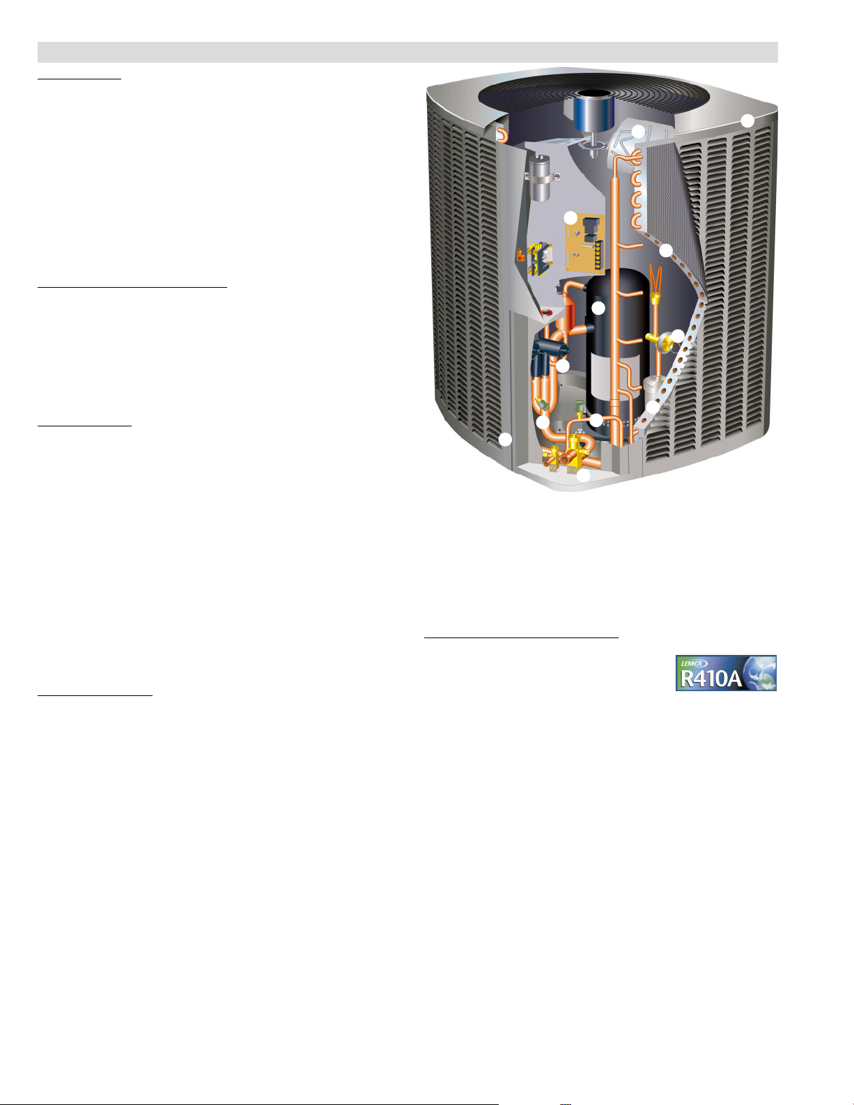
REFRIGERATION SYSTEM
Refrigerant
Non−chlorine, ozone friendly, R−410A.
Unit is factory pre−charged. See
Specification table.
Total system refrigerant charge is dependant on outdoor
unit size, indoor unit size and refrigerant line length. Refer
to charging procedures in the Installation Instructions to
determine correct amount of charge required.
Outdoor Coil Fan
B
Direct drive fan moves large air volumes uniformly
through entire condenser coil for high refrigerant cooling
capacity.
Vertical air discharge minimizes operating sounds and
eliminates damage to lawn and shrubs.
Fan motor has sleeve bearings and is inherently
protected.
Motor totally enclosed for maximum protection from
weather, dust and corrosion
Fan guard constructed of corrosion−resistant PVC
(polyvinyl chloride) coated steel.
Fan service access accomplished by removal of fan
guard.
K
XP16 − 2 to 5 Ton Heat Pump / Page 2
Page 3

FEATURES
REFRIGERATION SYSTEM (CONTINUED)
Copper Tube/Enhanced Fin Coil
C
Lennox designed and fabricated coil.
Ripple−edged aluminum fins.
Copper tube construction.
Lanced fins provide maximum exposure of fin surface to
air stream resulting in excellent heat transfer.
Fin collars grip tubing for maximum contact area.
Inverted coil circuiting prevents ice buildup at coil base in
low ambients. Discharge gas enters bottom of coil during
defrost and heat of refrigerant flows counter to water
drainage resulting in extremely clean and unobstructed
fins and tubes.
Fin spacing allows rapid and complete water drainage.
Flared shoulder tubing connections/silver soldering
construction.
Coil is factory tested under high pressure to insure
leakproof construction.
Entire coil is accessible for cleaning.
Expansion Valve − Outdoor Unit
D
Designed and sized specifically for use in heat pump
system.
Sensing bulb is located on the line between reversing valve
and the coil thus sensing suction temperature in any cycle.
Factory installed and piped.
Discharge Temperature Switch
Shuts off unit if operating conditions cause the
compressor discharge line temperature to rise above
setpoint.
Protects compressor from excessive pressure /
temperature.
Automatic reset when temperature drops below setpoint.
High Pressure Switch
E
Shuts off unit if abnormal operating conditions cause the
discharge pressure to rise above setting.
Protects compressor from excessive condensing
pressure.
Manual reset.
Low Pressure Switch
F
Shuts off unit if suction pressure falls below setting.
Provides loss of charge and freeze-up protection.
Automatic reset.
Hi-Capacity Liquid Line Drier
G
Factory installed in the liquid line, the drier traps moisture
or dirt that could contaminate the refrigerant system.
100% molecular−sieve bead type drier.
Reversing Valve
H
4-way interchange reversing valve effects a rapid change
in direction of refrigerant flow resulting in quick
changeover from cooling to heating and vice versa.
Valve operates on pressure differential between outdoor
unit and indoor unit of the system. Factory installed.
OPTIONS
Expansion Valve Kits
Must be ordered extra and field installed on certain indoor
units. See ARI Ratings tables.
Chatleff style fitting.
Freezestat
Installs on or near the discharge line of the evaporator or
on the suction line.
Senses suction line temperature and cycles the
compressor off when suction line temperature falls below
it’s setpoint.
Opens at 29°F and closes at 58°F.
Refrigerant Line Kits
Refrigerant lines (suction & liquid) are shipped
refrigeration clean. Lines are cleaned, dried, pressurized,
and sealed at factory.
Suction line fully insulated.
L15 lines are stubbed at both ends.
See Specifications table for selection.
Not available for −060 model and must be field fabricated.
COMPRESSOR
Copeland Scroll Ultra Techt Two−Stage Compressor
I
Compressor features high
efficiency with uniform
suction flow, constant
discharge flow and high
volumetric efficiency and
quiet operation.
Compressor consists of
two involute spiral scrolls
matched together to
generate a series of
crescent shaped gas
pockets between them.
During compression, one
scroll remains stationary
while the other scroll orbits
around it.
Gas is drawn into the outer
pocket, the pocket is sealed as the scroll rotates.
As the spiral movement continues, gas pockets are
pushed to the center of the scrolls. Volume between the
pockets is simultaneously reduced.
When pocket reaches the center, gas is now at high
pressure and is forced out of a port located in the center
Slider Ring
Fixed scroll
efficiency.
Scroll compressor is tolerant to the effects of slugging
and contaminants. If this occurs, scrolls separate,
allowing liquid or contaminants to to be worked toward
the center and discharged.
On the fixed scroll there are two bypass ports in the first
suction pocket. On the outside of the fixed scroll there is a
slider ring" that is controlled by an internal solenoid that
will rotate and cover the bypass ports. When the
thermostat calls for first−stage cooling, the bypass ports
are open and the compressor operates at 67% capacity,
creating more cost−effective and efficient compressor
operation. The bypassed refrigerant is returned to the
compressor housing through the bypass ports. When
the thermostat calls for second−stage cooling, the
internal solenoid is energized, the slider ring rotates and
covers the bypass ports, and the compressor operates
at full capacity.
Low gas pulses during compression reduces
operational sound levels.
Compressor motor is internally protected from
excessive current and temperature.
Compressor is installed in the unit on specially
formulated, resilient rubber mounts for better sound
dampening and vibration free operation.
Internal solenoid
XP16 − 2 to 5 Ton Heat Pump / Page 3
Slider
Ring
Internal
solenoid
of the fixed scrolls. During
compression, several
pockets are compressed
simultaneously resulting in
a smooth continuous
compression cycle.
Continuous flank contact,
maintained by centrifugal
force, minimizes gas
leakage and maximizes
Page 4
FEATURES
COMPRESSOR (CONTINUED)
Crankcase Heater
Crankcase heater prevents migration of liquid refrigerant
into compressor and ensures proper compressor
lubrication.
CONTROLS
Defrost Control
J
Solid-state control furnished as standard.
Gives a demand defrost cycle whenever system heating
performance falls below optimum levels. The sensing
element on coil determines when defrost cycle is required
and when to terminate cycle.
Anti−short cycle (5 minutes) incorporated into the board.
Diagnostic LED’s furnished as an aid in troubleshooting.
Conveniently located in control box.
OPTIONS
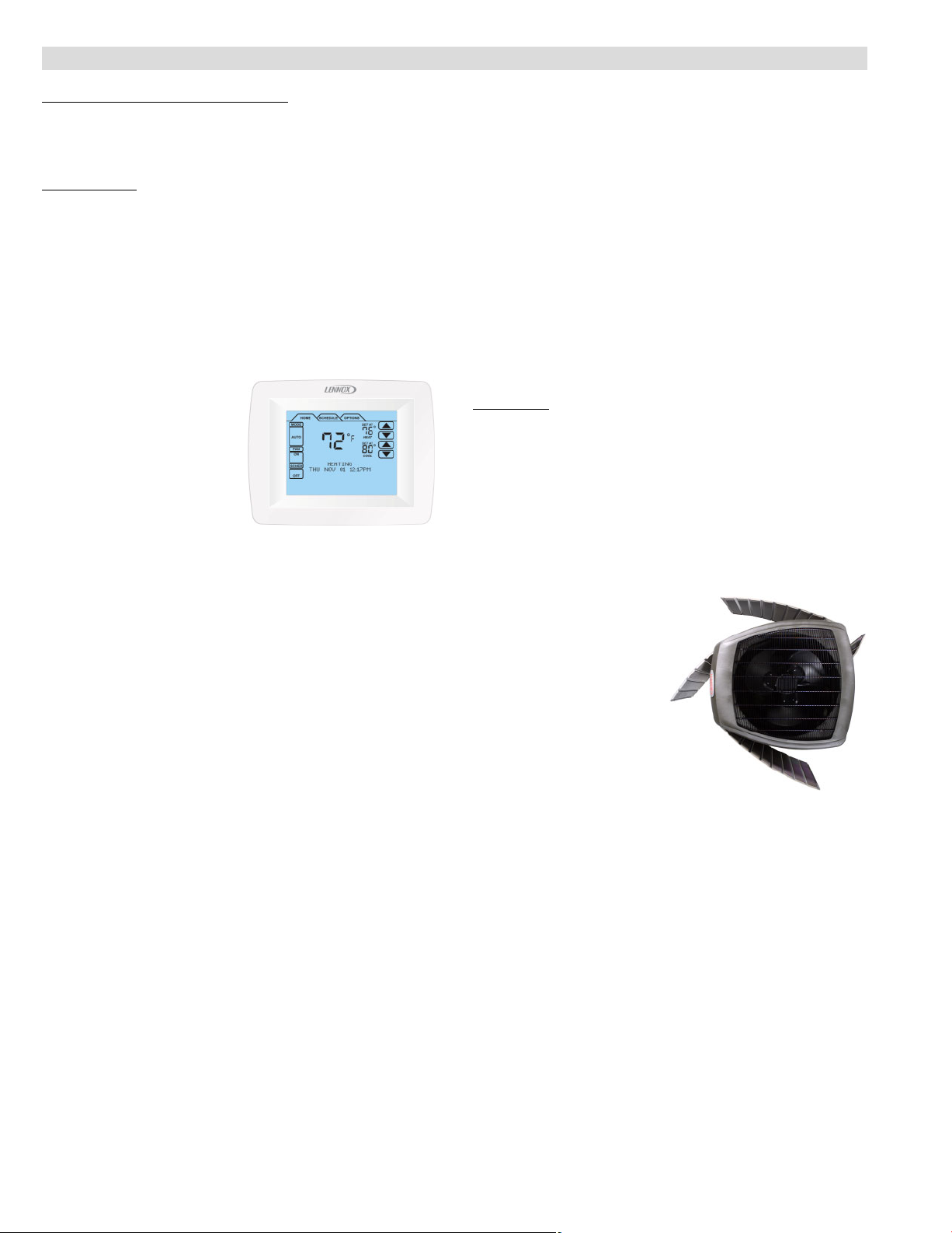
ComfortSenset 7000 Touchscreen Thermostat
Electronic 7−day, universal,
multi−stage, programmable,
touchscreen thermostat.
4 Heat/2 Cool.
Auto−changeover.
Controls humidity during
cooling mode.
Offers enhanced
capabilities including
humidification / dehumidification / dewpoint measurement
and control, Humiditrol
maintenance reminders.
Easy−to−use, menu driven thermostat with a back−lit, LCD
touchscreen.
Remote outdoor temperature sensor (optional) allows the
thermostat to display outdoor temperature. Required in
dual fuel and Humiditrol
See the ComfortSenset 7000 Engineering Handbook
bulletin in the Controls section for more information.
Compressor Hard Start Kit
Single−phase units are equipped with a PSC compressor
motor.
This type of motor normally does not need a potential
relay and start capacitor.
In conditions such as low voltage, kit may be required to
increase the compressor starting torque.
Hard start kit is required in applications where the supply
voltage is less than 230V.
Indoor Blower Off Delay Relay
Delays the indoor blower−off time during the cooling cycle.
See ARI Rating Tables for usage.
Indoor Blower Speed Relay Kit
Relay kit provides optimum humidity control conditions by
automatically reducing indoor blower speed during
continuous fan or first−stage compressor operation.
Low Ambient Kit
Heat pump will operate in the cooling mode satisfactorily
down to 45_F outdoor air temperature without any additional
controls.
Kit can be added in the field enabling unit to operate
properly down to 30_F.
A Freezestat should be installed on compressors
equipped with a low ambient kit.
A Compressor Low Ambient Cut−Off should be added to
terminate compressor operation below recommended
operation conditions (on/off operation, 30°F or modulating
operation, 0°F.
®
control, and equipment
®
applications.
Mild Weather Kit
Heat pump units operate satisfactorily in the heating
mode at outdoor air temperatures up to 75_F.
Mild Weather Kit can be field installed, allowing heating
operation above 75_F.
Monitor Kit − Service Light
Contains ambient compensating thermistor and service
light thermostat.
For use with thermostats requiring input for indicator
lights.
Outdoor Thermostat Kit
An outdoor thermostat can be used to lock out some of the
electric heating elements on indoor units where two−stage
control is applicable.
Outdoor thermostat maintains the heating load on the low
power input as long as possible before allowing the full
power load to come on the line.
Thermostat kit and mounting box must be ordered extra.
Cabinet
K
Heavy−gauge steel construction
Pre−painted cabinet finish.
Pre−painted base section.
Control box is conveniently located with all controls
factory wired.
Large removable panel provides service access.
Drainage holes are provided in base section for moisture
removal.
High density polyethylene unit support feet raise the unit off
of the mounting surface, away from damaging moisture.
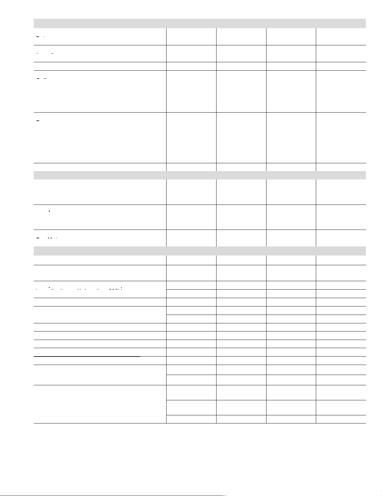
SmartHinget Louvered Coil Protection
L
Steel louvered panels
provides complete coil
protection.
Panels are hinged to
allow easy cleaning
and servicing of coils.
Panels may be
completely removed.
Interlocking tabs and
slots assure tight fit on
cabinet.
Refrigerant Line Connections, Electrical Inlets and
Service Valves
Vapor and liquid lines are located on corner of unit cabinet
and are made with sweat connections. See dimension
drawing.
Fully serviceable brass service valves prevent corrosion
M
and provide access to refrigerant system. Vapor valve can
be fully shut off, while liquid valve may be front seated to
manage refrigerant charge while servicing system.
Refrigerant line connections and field wiring inlets are
located in one central area of the cabinet. See dimension
drawing.
XP16 − 2 to 5 Ton Heat Pump / Page 4
Page 5
SPECIFICATIONS
p
p q
General
Data
Connections
(sweat)
Refrigerant
Outdoor
1
R−410A charge furnished 7 lbs. 13 oz. 10 lbs. 4 oz. 15 lbs. 7 oz. 11 lbs. 7 oz.
Net face area − sq. ft. Outer coil 13.22 18.67 24.5 24.93
Nominal Tonnage 2
Liquid line (o.d.) − in. 3/8 3/8 3/8 3/8
Vapor line (o.d.) − in. 3/4
Coil
Tube diameter − in. 5/16 5/16 5/16 5/16
Outdoor
Fan
Shipping Data − lbs. 1 pkg. 219 265 309 345
ELECTRICAL DATA
Line voltage data − 60hz
2
Maximum overcurrent protection (amps) 20 35 45 60
3
Minimum circuit ampacity 14.0 22.0 28.2 33.9
Compressor
Locked rotor amps 52 82 96 118
Outdoor Coil
Fan Motor
Locked rotor amps 2
OPTIONAL ACCESSORIES − must be ordered extra
ComfortSenset 7000 Thermostat Y0349 S S S S
Outdoor Temperature Sensor − for
ComfortSenset 7000 Thermostat
Compressor Hard Start Kit − Required
in applications with less than 230V
Compressor Low Ambient Cut−Off 45F08 S S S S
Freezestat
Indoor Blower Speed Relay Kit 40K58 S S S S
Indoor Blower Off Delay Relay 58M81 S S S S
Low Ambient Kit 68M04 S S S S
Mild Weather Kit 33M07 S S S S
Monitor Kit − Service Light 76F53 S S S S
Outdoor
Thermostat
Kit
Refrigerant
Line Sets
NOTE − Extremes of operating range are plus 10% and minus 5% of line voltage.
1
Refrigerant charge sufficient for 15 ft. length of refrigerant lines.
2
HACR type breaker or fuse.
3
Refer to National or Canadian Electrical Code manual to determine wire, fuse and disconnect size requirements.
4
Hard start kit is required in applications where the supply voltage is less than 230V.
3/8 in. tubing 93G35 S S S S
5/8 in. tubing 50A93 S S S S
Thermostat 56A87 S S S S
Mounting Box 31461 S
L15−41−20
L15−41−30
L15−65−30 L15−65−40
Model No. XP16−024 XP16−036 XP16−048 XP16−060
3 4 5
7/8 7/8 1−1/8
Inner coil 12.65
18.0 23.64 24.14
No. of rows 2 2 2 2
Fins per inch 22 22 22 22
Diameter − in. 18 22 22 26
No. of blades 3
4 4 3
Motor hp 1/10 1/6 1/4 1/3
Cfm 2215 3150 3980 4380
Rpm 1040 844 836 850
Watts 145 215 305 280
4
208/230V−1ph
4
208/230V−1ph
4
208/230V−1ph
4
208/230V−1ph
Rated load amps 10.25 16.67 21.15 25.87
Power factor 0.98 0.99 0.99 0.99
Full load amps 1.1 1.1 1.7 1.8
2.1 3.1 2.9
X2658 S S S S
10J42 S S
81J69
S S
S S S
L15−41−40
S
L15−41−50
S S
L15−65−50
Field Fabricate S
XP16 − 2 to 5 Ton Heat Pump / Page 5
Page 6

DIMENSIONS − INCHES (MM)
TOP VIEW
DISCHARGE AIR
SUCTION LINE
CONNECTION
LIQUID LINE
CONNECTION
BC
LIQUID LINE
CONNECTION
UNIT SUPPORT
FEET
8−1/2
(216)
8−3/4
(222)
5−1/2
(140)
SIDE VIEW
13−1/2
(343)
ELECTRICAL
INLETS
SUCTION LINE
CONNECTION
4−1/4(108)
9−1/2
(241)
8−1/4
(210)
4−3/4
(121)
A
2 (51)
UNIT SUPPORT
FEET
D
E
1 (25)
F
END VIEW
K
J
G
H
Model No.
XP16−024
XP16−024 BASE SECTION
A B C D E F G H J K
in.
mm in. mm in. mm in. mm in. mm in. mm in. mm in. mm in. mm in. mm
31 787 27 686 28 711 − − − − − − − − − − − − − − − − − − − − −
XP16−036 TO −060 BASE SECTION
XP16−036 35 889 30−1/2 775 35 889 13−7/8 352 7−3/4 197 3−1/4 83 27−1/8 689 3−5/8 92 4−1/2 114 20−5/8 524
XP16−048 45 991 30−1/2 775 35 889 13−7/8 352 7−3/4 197 3−1/4 83 27−1/8 689 3−5/8 92 4−1/2 11 4 20−5/8 524
XP16−060 39 991 35−1/2 902 39−1/2 1003 16−7/8 429 8−3/4 222 3−1/8 79 30−3/4 781 4−5/8 11 7 3−3/4 95 26−7/8 683
XP16 − 2 to 5 Ton Heat Pump / Page 6
Page 7

INSTALLATION CLEARANCES
Model No
Number
See NOTES
NOTES:
Service clearance of 30 in. (762 mm) must be maintained on one
of the sides adjacent to the control box.
Clearance to one of the other three sides must be 36 in. (914 mm).
See
NOTES
See
NOTES
Clearance to one of the remaining two sides may be 12 in. (305
mm) and the final side may be 6 in. (152 mm).
A clearance of 24 in. (610 mm) must be maintained between two
units.
See NOTES
Control
Box
48 in. (1219 mm) clearance required on top of unit.
OUTDOOR SOUND DATA
1
Unit
Octave Band Sound Power Levels dBA, re 10
.
63
125 250 500 1000 2000 4000 8000
Center Frequency − HZ
−12
Watts
XP16-024 79.0 72.0 70.0 69.5 68.5 63.5 58.0 56.5 74
XP16-036 80.5 70.5 71.5 71.0 68.5 63.5 58.5 53.5 76
XP16-048 81.0 72.5 71.5 73.0 70.5 66.0 60.5 58.5 76
XP16-060 80.5 72.5 73.5 77.5 72.5 67.0 62.5 58.5 78
NOTE − the octave sound power data does not include tonal correction.
1
Tested according to ARI Standard 270-95 test conditions.
1
Sound
Rating
(dB)
FIELD WIRING
DISCONNECT
SWITCH
(By Others)
A
OPTIONAL
OUTDOOR
THERMOSTAT
LENNOX
OUTDOOR
UNIT
OPTIONAL
ELECTRIC
HEAT
LENNOX
INDOOR UNIT
B
DISCONNECT
SWITCH
(By Others)
THERMOSTAT
(Optional)
CD
A Two Wire Power (see Electrical Data)
B Two or Three Wire Power (size to heater capacity)
C Twelve Wire Low Voltage 18 ga. minimum
Fourteen Wire Low Voltage with Optional Outdoor Thermostat
D Eight Wire Low Voltage 18 ga. minimum
Ten Wire Low Voltage with Optional Outdoor Thermostat
Field Wiring Not Furnished
All wiring must conform to NEC or CEC and local electrical codes.
XP16 − 2 to 5 Ton Heat Pump / Page 7
Page 8

ARI RATINGS − INDOOR COIL / AIR HANDLER SUBSTITUTION
Substituting Coils in the ARI Tables
Most R−22 and R−410A indoor coils and air handlers are
the same except for the factory installed expansion
device. C33 coils can be used in place of the CX34 coils,
CB26UH−R, CB27UH, and CB30M air handlers can be
used in place of the CBX26UH, CBX27UH, CBX32M and
CBX32MV, respectively.
UP−FLOW COILS
R−410A R−22
CX34−18/24A−6F
CX34−18/24B−6F =
CX34−18/24C−6F =
CX34−19A−6F
CX34−25A−6F
CX34−25B−6F
CX34−30A−6F
CX34−30B−6F
CX34−30C−6F
CX34−31A−6F
CX34−31B−6F
CX34−36A−6F
CX34−36B−6F
CX34−36C−6F
CX34−38A−6F
CX34−38B−6F
CX34−42B−6F = C33−42B−2
CX34−43B−6F = C33−43B−2
CX34−43C−6F = C33−43C−2
no equivalent
CX34−44/48B−6F
CX34−44/48C−6F
CX34−49C−6F
CX34−50/60C−6F
CX34−60D−6F
CX34−62C−6F
CX34−62D−6F
=
C33−24A−2
C33−24B−2
C33−24C−2
=
C33−19A−2
=
C33−25A−2
=
C33−25B−2
=
C33−30A−2
=
C33−30B−2
=
C33−30C−2
=
C33−31A−2
=
C33−31B−2
=
C33−36A−2
=
C33−36B−2
=
C33−36C−2
=
C33−38A−2
=
C33−38B−2
C33−44C−2
=
C33−48B−2
=
C33−48C−2
=
C33−49C−2
=
C33−50/60C−2
=
C33−60D−2
=
C33−62C−2
=
C33−62D−2
The expansion device is based on the size of the outdoor
unit. The factory installed RFC or TXV on the
C33/CB26UH−R/CB27UH/CB30M must be replaced to
correspond to the outdoor unit. The correct TXV’s are:
2−3 ton heat pumps 49L24
4−5 ton heat pumps 91M02
Example:
A four−ton heat pump is being installed. The ARI table
shows that CBX32M−048 is a matching air handler. A
CB30M−51 with a 91M02 TXV can be used in its place.
AIR HANDLERS
CBX26UH−018
CBX26UH−024 = CB26UH−024−R
CBX26UH−030 = CB26UH−030−R
CBX26UH−036
CBX26UH−042 = CB26UH−042−R
CBX26UH−048 = CB26UH−048
CBX26UH−060
CBX27UH−018/024 = CB27UH−018/024
CBX27UH−030 = CB27UH−030
CBX27UH−036
CBX27UH−042 = CB27UH−042
CBX27UH−048 = CB27UH−048
CBX27UH−060
CBX32M−018/024 = CB30M−21/26
CBX32M−030 = CB30M−31
CBX32M−036
CBX32M−042 = CB30M−46
CBX32M−048 = CB30M−51
CBX32M−060
CBX32MV−(all) no equivalent
R−410A R−22
= CB26UH−018−R
= CB26UH−036−R
= CB26UH−060−R
= CB27UH−036
= CB27UH−060
= CB30M−41
= CB30M−65
XP16 − 2 to 5 Ton Heat Pump / Page 8
Page 9

ARI RATINGS
Expansion
Cooli
Cool
High
Low
High
Low
1
ARI Standard 210/240 Ratings
Capacity − Btuh Efficiency Total Watts COP
ng
High
Tem p.
Heating
Low
Tem p.
Heating
HSPF
SEER EER IV V
High Low High Low
Heat
Heat
Heat
Heat
XP16−024 2 TON
Air Handlers Air Handlers
23,800 21,800 13,000 15.70 11.7 0 8.00 6.70 2025 1810 1600 3.52 2.38
23,400 22,000 13,300 14.20 11.0 0 7.70 6.70 2110 1910 1695 3.38 2.30
24,000 22,200 13,400 15.00 11.2 0 7.70 6.70 2130 1885 1685 3.46 2.32 CBX26UH−018 (Up−Flow / Horizontal) Factory TXV
24,200 21,600 12,900 16.00 12.00 8.20 7.00 1970 1725 1525 3.66 2.48
24,200 21,600 12,800 16.00 12.20 8.20 7.00 1960 1715 1515 3.70 2.48
24,200 22,000 13,300 15.00 11.5 0 8.00 6.70 2095 1845 1645 3.50 2.36 CBX26UH−024 (Up−Flow / Horizontal) Factory TXV
24,400 21,600 12,800 17.00 12.50 8.50 7.20 1940 1680 1490 3.76 2.52
24,200 22,200 13,400 15.20 11.5 0 8.00 7.00 2105 1820 1635 3.58 2.40
24,800 22,000 13,000 17.00 12.20 8.50 7.20 1995 1685 1515 3.82 2.52
Up−Flow Indoor Coils Up−Flow Coils
23,600 22,200 13,400 14.00 11.0 0 7.70 6.70 2145 1910 1700 3.40 2.30
Up−Flow Indoor Coils + Furnaces Up−Flow Coils + Furnaces
23,800 21,400 12,700 16.00 12.00 7.70 6.70 1975 1800 1585 3.48 2.34 CX34−36C−6F
23,800 21,400 12,700 16.00 12.00 7.70 6.70 1975 1800 1585 3.48 2.34 CX34−36C−6F
23,800 21,400 12,800 16.00 11.7 0 7.70 6.70 2000 1810 1600 3.46 2.34 CX34−36A−6F
23,800 21,400 12,800 16.00 11.7 0 7.70 6.70 2000 1810 1600 3.46 2.34 CX34−36B−6F
23,800 21,400 12,800 16.00 11.7 0 7.70 6.70 2000 1810 1600 3.46 2.34 CX34−36B−6F
24,000 21,400 12,700 16.20 12.00 7.70 6.70 2000 1840 1620 3.40 2.30 CX34−25A−6F
24,000 21,400 12,700 16.20 12.00 7.70 6.70 2000 1840 1620 3.40 2.30 CX34−25B−6F
24,000 21,400 12,700 16.20 12.00 7.70 6.70 2000 1840 1620 3.40 2.30 CX34−25B−6F
24,000 21,400 12,700 16.20 12.00 8.00 6.70 1975 1785 1575 3.52 2.36 CX34−36B−6F
24,000 21,400 12,800 16.00 11.7 0 7.70 6.70 2010 1845 1625 3.40 2.30 CX34−25B−6F
24,000 21,600 12,900 16.00 11.7 0 7.70 6.70 2010 1815 1605 3.48 2.36 CX34−36B−6F
24,200 21,200 12,700 16.20 12.20 7.70 6.70 1970 1815 1595 3.42 2.34 CX34−25B−6F
24,400 21,400 12,700 16.20 12.00 7.70 6.70 2005 1840 1620 3.40 2.30 CX34−31B−6F
24,400 21,400 12,700 16.20 12.00 7.70 6.70 2005 1840 1620 3.40 2.30 CX34−31B−6F
24,400 21,400 12,700 16.20 12.00 7.70 6.70 2005 1840 1620 3.40 2.30 CX34−31A−6F
24,400 21,400 12,800 16.20 12.00 7.70 6.70 2015 1845 1625 3.40 2.30 CX34−31B−6F
24,400 21,600 12,900 16.20 12.20 8.20 7.00 1980 1730 1525 3.66 2.48 CX34−38B−6F
24,400 21,800 13,000 16.00 12.00 8.20 7.00 2015 1765 1560 3.62 2.44 CX34−38B−6F
24,400 21,800 13,000 16.20 12.00 8.20 7.00 2005 1755 1555 3.64 2.44 CX34−38A−6F
24,400 21,800 13,000 16.20 12.00 8.20 7.00 2005 1755 1555 3.64 2.44 CX34−38B−6F
24,400 21,800 13,000 16.20 12.00 8.20 7.00 2005 1755 1555 3.64 2.44 CX34−38B−6F
24,400 21,600 12,900 16.20 12.20 8.20 7.00 1980 1730 1525 3.66 2.48 CX34−38B−6F
24,400 21,800 13,000 16.20 12.00 8.20 7.00 2005 1755 1555 3.64 2.44 CX34−38A−6F
24,600 21,200 12,700 16.50 12.20 7.70 6.70 1980 1815 1590 3.42 2.34 CX34−31B−6F
Down−Flow Indoor Coils Down−Flow Coils
23,200 22,200 13,400 14.00 10.85 7.70 6.70 2135 1925 1705 3.38 2.30
23,600 22,400 13,500 14.20 11.0 0 7.70 6.70 2135 1885 1685 3.48 2.34
NOTE − When used with gas furnaces, a dual−fuel control (i.e. FM21) or a control system with dual−fuel capabilities (i.e. Harmony III, LZP−2 or LZP−4) must be used (ordered extra).
1
Certified in accordance with USE certification program which is based on ARI Standard 210/240 with 25 ft. of connecting refrigerant lines;
Cooling Ratings − 95_F outdoor air temperature and 80_F db/67_F wb entering indoor coil air.
High Temperature Heating Ratings − 47_F db/43_F wb outdoor air temperature and 70_F db entering indoor coil air.
Low Temperature Heating Ratings − 17_F db/15_F wb outdoor air temperature and 70_F db entering indoor coil air.
2
Factory installed expansion valve or RFC on indoor unit MUST be replaced with valve specified (if equipped).
3
Blower must be capable of time−off blower delay. Indoor Blower Off Delay Relay (58M81) is recommend for field installation.
4
Blower control must be set for a time−off blower delay.
5
Most popular air handler combination.
Indoor Unit Model No.
4
CBX32MV−018/024 (Multi−Position) Factory TXV
3
CBX32M−018/024 (Multi−Position) Factory TXV
4,5
CBX32MV−024/030 (Multi−Position) Factory TXV
4
CBX27UH−024 (Up−Flow/Horizontal) Factory TXV
4
CBX27UH−030 (Up−Flow/Horizontal) Factory TXV
4
CBX32M−030 (Multi−Position) Factory TXV
4
CBX32MV−036 (Multi−Position) Factory TXV
3
CX34−38A/B−6F Factory TXV
4
G61MPV−36C−090 Factory TXV
4
G71MPP−36C−090 Factory TXV
4
G60UHV−36A−070 Factory TXV
4
G61MPV−36B−070 Factory TXV
4
G71MPP−36B−070 Factory TXV
4
G60UHV−36A−070 Factory TXV
4
G61MPV−36B−070 Factory TXV
4
G71MPP−36B−070 Factory TXV
4
G60UHV−36B−090 Factory TXV
4
G61MPV−36B−045 Factory TXV
4
G61MPV−36B−045 Factory TXV
4
G60UHV−36B−090 Factory TXV
4
G61MPV−36B−070 Factory TXV
4
G71MPP−36B−070 Factory TXV
4
G60UHV−36A−070 Factory TXV
4
G61MPV−36B−045 Factory TXV
4
G60UHV−36B−090 Factory TXV
4
G61MPV−36B−045 Factory TXV
4
G60UHV−36A−070 Factory TXV
4
G61MPV−36B−070 Factory TXV
4
G71MPP−36B−070 Factory TXV
4
G60UHV−36B−090 Factory TXV
4
G60UHV−36A−070 Factory TXV
4
G60UHV−36B−090 Factory TXV
3
CR33−24A/B−F
3
CR33−30/36A/B/C−F
Device
2
49L24
2
49L24
XP16 − 2 to 5 Ton Heat Pump / Page 9
Page 10

ARI RATINGS
Expansion
Cooli
T
T
Cool
High
Low
High
Low
1
ARI Standard 210/240 Ratings
Capacity − Btuh Efficiency Total Watts COP
ng
High
emp.
Heating
Low
emp.
Heating
HSPF
SEER EER IV V
High Low High Low
Heat
Heat
Heat
Heat
XP16−024 2 TON
Down−Flow Indoor Coils + Furnaces Down−Flow Coils + Furnaces
23,800 21,800 13,100 15.70 11.7 0 8.00 7.00 2015 1790 1580 3.56 2.42 CR33−24B−F
23,800 21,800 13,100 15.70 11.7 0 8.00 7.00 2015 1790 1580 3.56 2.42 CR33−24B−F
23,800 21,800 13,100 15.70 11.7 0 8.00 7.00 2025 1795 1585 3.56 2.42 CR33−24B−F
24,000 21,800 13,100 15.70 11.7 0 8.20 7.00 2035 1780 1575 3.58 2.44 CR33−24A−F
24,200 21,800 12,900 16.20 12.20 8.20 7.20 1970 1720 1520 3.72 2.48 CR33−30/36C−F
24,200 21,800 12,900 16.20 12.20 8.20 7.20 1970 1720 1520 3.72 2.48 CR33−30/36C−F
24,200 21,800 13,000 16.20 12.00 8.20 7.20 2005 1730 1535 3.70 2.48 CR33−30/36B−F
24,200 21,800 13,000 16.20 12.00 8.20 7.20 2005 1730 1535 3.70 2.48 CR33−30/36B−F
24,200 22,000 13,100 16.20 12.00 8.20 7.20 2015 1735 1545 3.72 2.48 CR33−30/36B−F
24,400 22,000 13,100 16.50 12.00 8.20 7.20 2015 1720 1540 3.74 2.50 CR33−30/36A−F
24,600 22,000 13,100 16.70 12.20 8.50 7.20 2005 1690 1515 3.82 2.54 CR33−30/36B−F
Horizontal Indoor Coils Horizontal Coils
23,800 22,400 13,500 14.00 10.95 7.70 6.70 2175 1925 1745 3.42 2.26
Horizontal Indoor Coils + Furnaces Horizontal Coils + Furnaces
24,000 21,400 12,700 16.20 12.00 7.70 6.70 2000 1855 1620 3.38 2.30 CH33−36A−2F
24,000 21,400 12,700 16.20 12.00 8.00 6.70 1975 1785 1575 3.52 2.36 CH33−36B−2F
24,000 21,400 12,700 16.20 12.00 8.00 6.70 1975 1785 1575 3.52 2.36 CH33−36B−2F
24,000 21,400 12,700 16.50 12.20 8.00 6.70 1955 1765 1550 3.56 2.40 CH33−36B−2F
24,000 21,400 12,800 16.20 12.00 7.70 6.70 1990 1790 1580 3.50 2.38 CH33−36B−2F
24,200 21,400 12,700 16.20 12.20 8.00 6.70 1955 1740 1550 3.60 2.40 CH33−36C−2F
24,200 21,400 12,700 16.20 12.20 8.00 6.70 1955 1740 1550 3.60 2.40 CH33−36C−2F
XP16−036 3 TON
Air Handlers Air Handlers
34,600 33,000 20,000 14.70 11 .2 0 8.00 6.70 3080 2980 2550 3.24 2.30
35,200 33,000 19,900 15.50 11 .5 0 8.00 7.00 3055 2900 2495 3.34 2.34
35,200 33,200 20,000 14.70 11 .2 0 8.00 7.00 3105 2950 2550 3.30 2.30
35,600 33,200 19,900 16.00 11 .7 0 8.20 7.00 3045 2865 2480 3.40 2.34
35,600 33,000 19,700 15.70 11 .7 0 8.20 7.00 3000 2835 2440 3.42 2.36
35,600 33,600 20,400 14.70 11 .2 0 8.20 7.20 3110 2895 2470 3.40 2.42 CBX26UH−030 (Up−Flow / Horizontal) Factory TXV
36,000 33,600 20,400 14.50 11 .5 0 8.20 7.20 3110 2865 2455 3.44 2.44 CBX26UH−036 (Up−Flow / Horizontal)
36,800 32,800 19,700 16.20 12.20 8.20 7.20 2970 2805 2385 3.42 2.42
Up−Flow Indoor Coils Up−Flow Coils
35,200 33,800 20,600 14.00 11 .0 0 8.00 7.00 3190 2995 2565 3.30 2.36
NOTE − When used with gas furnaces, a dual−fuel control (i.e. FM21) or a control system with dual−fuel capabilities (i.e. Harmony III, LZP−2 or LZP−4) must be used (ordered extra).
1
Certified in accordance with USE certification program which is based on ARI Standard 210/240 with 25 ft. of connecting refrigerant lines;
Cooling Ratings − 95_F outdoor air temperature and 80_F db/67_F wb entering indoor coil air.
High Temperature Heating Ratings − 47_F db/43_F wb outdoor air temperature and 70_F db entering indoor coil air.
Low Temperature Heating Ratings − 17_F db/15_F wb outdoor air temperature and 70_F db entering indoor coil air.
2
Factory installed expansion valve or RFC on indoor unit MUST be replaced with valve specified (if equipped).
3
Blower must be capable of time−off blower delay. Indoor Blower Off Delay Relay (58M81) is recommend for field installation.
4
Blower control must be set for a time−off blower delay.
5
Most popular air handler combination.
Indoor Unit Model No.
4
G61MPV−36B−070
4
G71MPP−36B−070
4
G61MPV−36B−045
4
G60DFV−36A−070
4
G61MPV−36C−090
4
G71MPP−36C−090
4
G61MPV−36B−070
4
G71MPP−36B−070
4
G61MPV−36B−045
4
G60DFV−36A−070
4
G60DFV−36B−090
3
CH33−36C−2F
4
G60UHV−36A−070
4
G61MPV−36B−070
4
G71MPP−36B−070
4
G60UHV−36B−090
4
G61MPV−36B−045
4
G61MPV−36C−090
4
G71MPP−36C−090
3
CBX32M−030 (Multi−Position) Factory TXV
4
CBX32MV−024/030 (Multi−Position) Factory TXV
3
CBX32M−036 (Multi−Position) Factory TXV
4,5
CBX32MV−036 (Multi−Position) Factory TXV
4
CBX27UH−036 (Up−Flow/Horizontal)
4
CBX27UH−042 (Up−Flow/Horizontal)
3
CX34−38A/B−6F Factory TXV
Device
2
49L24
2
49L24
2
49L24
2
49L24
2
49L24
2
49L24
2
49L24
2
49L24
2
49L24
2
49L24
2
49L24
2
49L24
2
49L24
2
49L24
2
49L24
2
49L24
2
49L24
2
49L24
2
49L24
2
49L24
2
49L24
2
49L24
XP16 − 2 to 5 Ton Heat Pump / Page 10
Page 11

ARI RATINGS
Expansion
Cooli
T
T
Cool
High
Low
High
Low
1
ARI Standard 210/240 Ratings
Capacity − Btuh Efficiency Total Watts COP
ng
High
emp.
Heating
Low
emp.
Heating
HSPF
SEER EER IV V
High Low High Low
Heat
Heat
Heat
Heat
XP16−036 3 TON
Up−Flow Indoor Coils + Furnaces Up−Flow Coils + Furnaces
35,600 33,600 20,400 15.20 11 .2 0 8.20 7.00 3125 2915 2490 3.38 2.40 CX34−38A−6F
35,600 33,600 20,400 15.20 11 .2 0 8.20 7.00 3145 2930 2505 3.36 2.38 CX34−38B−6F
35,600 33,400 20,200 15.20 11 .5 0 8.20 7.00 3100 2910 2475 3.36 2.38 CX34−38B−6F
35,600 33,400 20,200 15.20 11 .5 0 8.20 7.00 3100 2910 2475 3.36 2.38 CX34−38B−6F
35,800 33,200 20,000 15.70 11 .7 0 8.20 7.20 3040 2830 2405 3.44 2.44 CX34−38B−6F
36,200 32,200 19,500 16.00 11 .7 0 7.70 6.70 3035 3075 2580 3.06 2.22 C33−44C
36,200 32,200 19,500 16.00 11 .7 0 7.70 6.70 3035 3075 2580 3.06 2.22 C33−44C
36,400 32,000 19,400 16.00 12.00 7.70 6.70 3000 3080 2560 3.04 2.22 CX34−43C−6F
36,400 32,000 19,400 16.00 12.00 7.70 6.70 3000 3080 2560 3.04 2.22 CX34−43C−6F
36,400 32,200 19,500 16.00 11 .7 0 7.70 6.70 3040 3095 2585 3.04 2.20 CX34−43B−6F
Down−Flow Indoor Coils Down−Flow Coils
34,800 33,400 20,400 13.70 10.90 7.70 6.70 3190 3065 2610 3.20 2.28
35,800 34,000 20,600 14.20 11 .2 0 8.20 7.00 3195 2950 2555 3.38 2.36
Down−Flow Indoor Coils + Furnaces Down−Flow Coils + Furnaces
35,200 33,200 20,200 15.20 11 .2 0 8.00 7.00 3100 2980 2520 3.26 2.34 CR33−48B−F
35,200 33,200 20,200 15.20 11 .2 0 8.00 7.00 3100 2980 2520 3.26 2.34 CR33−48B−F
35,200 33,400 20,200 15.20 11 .2 0 8.00 7.00 3140 2995 2550 3.26 2.32 CR33−48B−F
35,400 32,800 19,800 15.70 11 .7 0 8.00 7.00 3000 2885 2425 3.34 2.40 CR33−48C−F
35,400 32,800 19,800 15.70 11 .7 0 8.00 7.00 3000 2885 2425 3.34 2.40 CR33−48C−F
35,400 32,800 19,900 15.50 11 .5 0 8.00 7.00 3015 2890 2435 3.32 2.40 CR33−48B−F
36,400 33,200 20,000 16.00 12.00 8.50 7.20 3005 2765 2370 3.52 2.48 CR33−50/60C−F
36,400 33,200 20,000 16.00 12.00 8.50 7.20 3005 2765 2370 3.52 2.48 CR33−50/60C−F
Horizontal Indoor Coils Horizontal Coils
34,800 33,600 20,400 13.70 10.95 7.70 6.70 3185 3045 2595 3.24 2.30
35,200 33,800 20,600 14.00 11 .0 0 8.00 7.00 3190 2980 2555 3.32 2.36
Horizontal Indoor Coils + Furnaces Horizontal Coils + Furnaces
35,800 32,200 19,500 15.70 11 .7 0 7.70 6.70 3035 3105 2590 3.04 2.20 CH33−42B−2F
36,200 32,000 19,400 16.00 12.00 7.70 6.70 3000 3085 2565 3.04 2.22 CH33−48C−2F
36,200 32,000 19,400 16.00 12.00 7.70 6.70 3000 3085 2565 3.04 2.22 CH33−48C−2F
36,200 32,200 19,500 16.00 11 .7 0 7.70 6.70 3040 3075 2585 3.06 2.20 CH33−44/48B−2F
XP16−048 4 TON
Air Handlers Air Handlers
47,000 44,500 26,400 16.00 11 .7 0 8.20 7.00 3995 3895 3315 3.34 2.34
47,000 45,000 26,800 15.70 11 .7 0 8.00 6.70 3960 3990 3375 3.30 2.32
47,000 44,500 26,600 14.70 11 .5 0 8.00 7.00 4055 3970 3380 3.28 2.30
47,500 45,000 27,000 15.70 12.00 8.00 7.00 3960 3910 3320 3.38 2.38
47,500 43,000 25,800 15.70 12.00 7.70 6.70 3945 4070 3400 3.10 2.22
47,500 44,000 26,000 16.00 12.00 8.20 7.00 3935 3865 3280 3.34 2.32
47,500 45,000 26,800 14.50 11 .2 0 8.00 6.70 4240 4045 3480 3.26 2.26
NOTE − When used with gas furnaces, a dual−fuel control (i.e. FM21) or a control system with dual−fuel capabilities (i.e. Harmony III, LZP−2 or LZP−4) must be used (ordered extra).
1
Certified in accordance with USE certification program which is based on ARI Standard 210/240 with 25 ft. of connecting refrigerant lines;
Cooling Ratings − 95_F outdoor air temperature and 80_F db/67_F wb entering indoor coil air.
High Temperature Heating Ratings − 47_F db/43_F wb outdoor air temperature and 70_F db entering indoor coil air.
Low Temperature Heating Ratings − 17_F db/15_F wb outdoor air temperature and 70_F db entering indoor coil air.
2
Factory installed expansion valve or RFC on indoor unit MUST be replaced with valve specified (if equipped).
3
Blower must be capable of time−off blower delay. Indoor Blower Off Delay Relay (58M81) is recommend for field installation.
4
Blower control must be set for a time−off blower delay.
5
Most popular air handler combination.
Indoor Unit Model No.
4
G60UHV−36A−070 Factory TXV
4
G61MPV−36B−045 Factory TXV
4
G61MPV−36B−070 Factory TXV
4
G71MPP−36B−070 Factory TXV
4
G60UHV−36B−090 Factory TXV
4
G61MPV−36C−090
4
G71MPP−36C−090
4
G61MPV−36C−090
4
G71MPP−36C−090
4
G60UHV−36B−090
3
CR33−48B/C−F
3
CR33−50/60C−F
4
G61MPV−36B−070
4
G71MPP−36B−070
4
G61MPV−36B−045
4
G61MPV−36C−090
4
G71MPP−36C−090
4
G60DFV−36B−090
4
G61MPV−36C−090
4
G71MPP−36C−090
3
CH23−51
3
CH23−65
4
G60UHV−36B−090
4
G61MPV−36C−090
4
G71MPP−36C−090
4
G60UHV−36B−090
4
CBX32MV−048 (Multi−Position) Factory TXV
4
CBX27UH−060 (Up−Flow/Horizontal) Factory TXV
3
CBX32M−048 (Multi−Position) Factory TXV
4
CBX27UH−048 (Up−Flow/Horizontal) Factory TXV
4
CBX32MV−068 (Multi−Position) Factory TXV
4,5
CBX32MV−060 (Multi−Position) Factory TXV
3
CBX32M−060 (Multi−Position) Factory TXV
Device
2
49L24
2
49L24
2
49L24
2
49L24
2
49L24
2
49L24
2
49L24
2
49L24
2
49L24
2
49L24
2
49L24
2
49L24
2
49L24
2
49L24
2
49L24
2
49L24
2
49L24
2
49L24
2
49L24
2
49L24
2
49L24
XP16 − 2 to 5 Ton Heat Pump / Page 11
Page 12

ARI RATINGS
Expansion
Cooli
Cool
High
Low
High
Low
1
ARI Standard 210/240 Ratings
Capacity − Btuh Efficiency Total Watts COP
ng
High
Tem p.
Heating
Low
Tem p.
Heating
HSPF
SEER EER IV V
High Low High Low
Heat
Heat
Heat
Heat
XP16−048 4 TON
Up−Flow Indoor Coils Up−Flow Coils
48,000 43,500 26,600 14.00 11 .0 0 8.00 7.00 4365 3875 3450 3.30 2.26 CX34−62D−6F Factory TXV
Up−Flow Indoor Coils + Furnaces Up−Flow Coils + Furnaces
47,500 43,500 26,000 15.70 11 .7 0 7.70 6.70 4010 4110 3450 3.10 2.20 CX34−60D−6F
48,000 44,000 26,200 15.70 11 .7 0 7.70 6.70 4090 4150 3510 3.10 2.18 CX34−60D−6F
48,500 43,000 25,800 15.70 11 .7 0 8.20 7.20 4145 3650 3225 3.46 2.34 CX34−62D−6F
48,500 43,500 26,200 15.70 11 .7 0 8.20 7.15 4145 3730 3325 3.42 2.30 CX34−62D−6F
48,500 43,500 26,200 15.70 11 .7 0 8.20 7.15 4145 3730 3325 3.42 2.30 CX34−62D−6F
Horizontal Indoor Coils Horizontal Coils
47,000 44,000 26,800 14.00 11 .0 0 7.70 6.70 4225 4180 3550 3.08 2.22
47,000 46,000 27,600 14.20 11 .2 0 8.20 7.00 4185 3845 3360 3.50 2.40
Horizontal Indoor Coils + Furnaces Horizontal Coils + Furnaces
47,500 43,500 26,000 15.70 11 .7 0 7.70 6.70 4045 4115 3470 3.10 2.20 CH33−60D−2F
47,500 43,500 26,000 15.70 11 .7 0 7.70 6.70 4005 4080 3425 3.12 2.22 CH33−62D−2F
47,500 44,000 26,400 15.50 11 .5 0 7.70 6.70 4095 4135 3500 3.12 2.20 CH33−62D−2F
47,500 44,000 26,400 15.50 11 .5 0 7.70 6.70 4095 4135 3500 3.12 2.20 CH33−62D−2F
XP16−060 5 TON
Air Handlers Air Handlers
57,000 51,500 32,600 15.20 11 .5 0 8.00 7.20 4935 4905 4225 3.08 2.26
57,000 52,500 33,200 15.50 11 .5 0 8.20 7.50 4965 4680 4075 3.28 2.38
57,500 53,000 33,600 14.50 11 .2 0 8.50 7.50 5090 4750 4170 3.28 2.36
58,000 52,000 33,200 14.70 11 .2 0 8.20 7.20 5105 4935 4350 3.08 2.24 CBX26UH−060 (Up−Flow / Horizontal) Factory TXV
56,500 52,500 33,200 15.20 11 .2 0 8.50 7.20 4985 4710 4115 3.26 2.36
Up−Flow Indoor Coils Up−Flow Coils
56,500 52,000 33,200 14.00 11 .0 0 7.70 7.00 5130 5125 4445 2.98 2.18
57,000 52,000 33,200 14.00 11 .0 0 7.70 7.00 5140 5160 4460 2.96 2.18
57,000 52,000 33,400 14.00 11 .0 0 7.70 7.00 5135 5105 4435 2.98 2.20
58,000 52,000 33,200 14.20 11 .2 0 7.70 7.00 5150 5080 4440 3.00 2.18
Up−Flow Indoor Coils + Furnaces Up−Flow Coils + Furnaces
57,000 51,500 32,800 15.20 11 .2 0 8.00 7.00 4990 4995 4310 3.02 2.22 CX34−60D−6F
57,000 51,500 32,800 15.20 11 .2 0 8.00 7.00 4990 4995 4310 3.02 2.22 CX34−60D−6F
57,000 51,500 33,000 14.50 11 .2 0 7.70 6.70 5095 5120 4420 2.94 2.18 CX34−49C−6F
57,000 51,500 33,000 14.50 11 .2 0 7.70 6.70 5095 5120 4420 2.94 2.18 CX34−49C−6F
57,000 51,500 33,000 15.00 11 .2 0 7.70 7.00 5040 5065 4365 2.98 2.22 CX34−49C−6F
57,000 51,500 33,000 15.00 11 .2 0 7.70 7.00 5045 5085 4375 2.96 2.20 CX34−49C−6F
Up−Flow Indoor Coils + Furnaces Continued on Next Page
NOTE − When used with gas furnaces, a dual−fuel control (i.e. FM21) or a control system with dual−fuel capabilities (i.e. Harmony III, LZP−2 or LZP−4) must be used (ordered extra).
1
Certified in accordance with USE certification program which is based on ARI Standard 210/240 with 25 ft. of connecting refrigerant lines;
Cooling Ratings − 95_F outdoor air temperature and 80_F db/67_F wb entering indoor coil air.
High Temperature Heating Ratings − 47_F db/43_F wb outdoor air temperature and 70_F db entering indoor coil air.
Low Temperature Heating Ratings − 17_F db/15_F wb outdoor air temperature and 70_F db entering indoor coil air.
2
Factory installed expansion valve or RFC on indoor unit MUST be replaced with valve specified (if equipped).
3
Blower must be capable of time−off blower delay. Indoor Blower Off Delay Relay (58M81) is recommend for field installation.
4
Blower control must be set for a time−off blower delay.
5
Most popular air handler combination.
Indoor Unit Model No.
4
G60UHV−60D−135 Factory TXV
4
G61MPV−60D−135 Factory TXV
4
G60UHV−60D−135 Factory TXV
4
G61MPV−60D−135 Factory TXV
4
G71MPP−60D−135 Factory TXV
3
CH33−62D−2F
3
CH23−68
4
G60UHV−60D−135
4
G60UHV−60D−135
4
G61MPV−60D−135
4
G71MPP−60D−135
4
CBX32MV−068 (Multi−Position) Factory TXV
4,5
CBX32MV−060 (Multi−Position) Factory TXV
3
CBX32M−060 (Multi−Position) Factory TXV
4
CBX27UH−060 (Up−Flow/Horizontal) Factory TXV
3
CX34−60D−6F Factory TXV
3
CX34−49C−6F Factory TXV
3
CX34−62D−6F Factory TXV
3
CX34−62C−6F Factory TXV
4
G61MPV−60D−135 Factory TXV
4
G71MPP−60D−135 Factory TXV
4
G61MPV−60C−110 Factory TXV
4
G71MPP−60C−110 Factory TXV
4
G60UHV−60C−090 Factory TXV
4
G60UHV−60C−110 Factory TXV
Device
2
91M02
2
91M02
2
91M02
2
91M02
2
91M02
2
91M02
XP16 − 2 to 5 Ton Heat Pump / Page 12
Page 13

ARI RATINGS
Expansion
Cooli
Cool
High
Low
High
Low
1
ARI Standard 210/240 Ratings
Capacity − Btuh Efficiency Total Watts COP
ng
High
Tem p.
Heating
Low
Tem p.
Heating
HSPF
SEER EER IV V
High Low High Low
Heat
Heat
Heat
Heat
XP16−060 5 TON
Up−Flow Indoor Coils + Furnaces (Continued) Up−Flow Coils + Furnaces
57,500 51,500 32,800 15.50 11 .5 0 8.00 7.20 4995 4915 4265 3.08 2.26 CX34−60D−6F
57,500 51,500 32,800 15.20 11 .5 0 8.00 7.00 5000 4980 4300 3.04 2.24 CX34−62D−6F
57,500 51,500 32,800 15.20 11 .5 0 8.00 7.00 5000 4980 4300 3.04 2.24 CX34−62D−6F
57,500 52,500 33,800 14.70 10.95 7.70 7.00 5255 5185 4525 2.96 2.18 CX34−49C−6F
57,500 52,500 33,800 14.70 10.95 7.70 7.00 5255 5185 4525 2.96 2.18 CX34−49C−6F
58,000 51,500 33,000 15.20 11 .2 0 8.00 7.00 5060 5005 4355 3.02 2.22 CX34−62C−6F
58,000 51,500 33,000 15.50 11 .5 0 8.00 7.00 5050 4985 4345 3.02 2.22 CX34−62C−6F
58,000 52,000 33,200 15.00 11 .2 0 7.70 7.00 5105 5040 4400 3.02 2.20 CX34−62C−6F
58,000 52,000 33,200 15.00 11 .2 0 7.70 7.00 5105 5040 4400 3.02 2.20 CX34−62C−6F
58,500 52,000 32,800 15.50 11 .7 0 8.00 7.20 5005 4895 4255 3.12 2.26 CX34−62D−6F
58,500 52,500 33,800 15.20 11 .0 0 8.00 7.00 5270 5105 4510 3.02 2.20 CX34−62C−6F
58,500 52,500 33,800 15.20 11 .0 0 8.00 7.00 5270 5105 4510 3.02 2.20 CX34−62C−6F
Down−Flow Indoor Coils Down−Flow Coils
55,500 53,000 33,800 13.70 10.85 8.20 7.20 5120 4820 4200 3.22 2.36 CR33−50/60C−F
55,500 53,000 33,800 13.70 10.85 8.20 7.20 5120 4820 4200 3.22 2.36 CR33−60D−F
Down−Flow Indoor Coils + Furnaces Down−Flow Coils + Furnaces
55,500 52,500 33,400 14.70 11 .0 0 8.50 7.50 5015 4730 4100 3.26 2.38 CR33−60D−F
55,500 52,500 33,400 14.70 11 .0 0 8.50 7.50 5015 4730 4100 3.26 2.38 CR33−60D−F
55,500 53,000 33,600 14.50 10.95 8.20 7.20 5075 4780 4155 3.24 2.36 CR33−50/60C−F
55,500 53,000 33,600 14.50 10.95 8.20 7.20 5075 4780 4155 3.24 2.36 CR33−50/60C−F
55,500 53,500 34,200 14.50 10.60 8.50 7.50 5235 4855 4270 3.22 2.34 CR33−50/60C−F
55,500 53,500 34,200 14.50 10.60 8.50 7.50 5235 4855 4270 3.22 2.34 CR33−50/60C−F
56,000 52,500 33,400 15.00 11 .2 0 8.50 7.50 4990 4685 4065 3.28 2.40 CR33−60D−F
56,000 52,500 33,400 15.00 11 .2 0 8.50 7.50 5000 4700 4080 3.28 2.40 CR33−50/60C−F
56,000 53,000 33,600 15.00 11 .0 0 8.50 7.50 5035 4700 4090 3.30 2.40 CR33−50/60C−F
Horizontal Indoor Coils Horizontal Coils
56,500 52,000 33,400 14.00 10.95 7.70 7.00 5170 5135 4460 2.96 2.20
56,500 52,000 33,400 14.00 11 .0 0 7.70 7.00 5130 5110 4420 2.98 2.22
57,500 54,000 34,000 14.20 11 .2 0 8.70 7.70 5145 4635 4090 3.42 2.44
Horizontal Indoor Coils + Furnaces Horizontal Coils + Furnaces
56,500 51,500 32,800 15.20 11 .2 0 7.70 7.00 4985 5040 4325 3.00 2.22 CH33−60D−2F
56,500 51,500 32,800 15.20 11 .2 0 7.70 7.00 4985 5040 4325 3.00 2.22 CH33−60D−2F
57,000 51,500 32,800 15.20 11 .2 0 8.00 7.00 4985 4985 4285 3.02 2.24 CH33−62D−2F
57,000 51,500 32,800 15.20 11 .2 0 8.00 7.00 4985 4985 4285 3.02 2.24 CH33−62D−2F
57,000 51,500 32,800 15.20 11 .2 0 8.00 7.00 4990 4955 4280 3.04 2.24 CH33−60D−2F
57,500 52,000 33,000 15.20 11 .5 0 8.00 7.20 4995 4900 4240 3.12 2.28 CH33−62D−2F
NOTE − When used with gas furnaces, a dual−fuel control (i.e. FM21) or a control system with dual−fuel capabilities (i.e. Harmony III, LZP−2 or LZP−4) must be used (ordered extra).
1
Certified in accordance with USE certification program which is based on ARI Standard 210/240 with 25 ft. of connecting refrigerant lines;
Cooling Ratings − 95_F outdoor air temperature and 80_F db/67_F wb entering indoor coil air.
High Temperature Heating Ratings − 47_F db/43_F wb outdoor air temperature and 70_F db entering indoor coil air.
Low Temperature Heating Ratings − 17_F db/15_F wb outdoor air temperature and 70_F db entering indoor coil air.
2
Factory installed expansion valve or RFC on indoor unit MUST be replaced with valve specified (if equipped).
3
Blower must be capable of time−off blower delay. Indoor Blower Off Delay Relay (58M81) is recommend for field installation.
4
Blower control must be set for a time−off blower delay.
5
Most popular air handler combination.
Indoor Unit Model No.
3
CH33−60D−2F
3
CH33−62D−2F
3
CH23−68
Device
4
G60UHV−60D−135 Factory TXV
4
G61MPV−60D−135 Factory TXV
4
G71MPP−60D−135 Factory TXV
4
G61MPV−60C−090 Factory TXV
4
G71MPP−60C−090 Factory TXV
4
G60UHV−60C−110 Factory TXV
4
G60UHV−60C−090 Factory TXV
4
G61MPV−60C−110 Factory TXV
4
G71MPP−60C−110 Factory TXV
4
G60UHV−60D−135 Factory TXV
4
G61MPV−60C−090 Factory TXV
4
G71MPP−60C−090 Factory TXV
2
91M02
2
91M02
4
G61MPV−60D−135
4
G71MPP−60D−135
4
G61MPV−60C−110
4
G71MPP−60C−110
4
G61MPV−60C−090
4
G71MPP−60C−090
4
G60DFV−60D−135
4
G60DFV−60C−110
4
G60DFV−60C−090
4
G61MPV−60D−135
4
G71MPP−60D−135
4
G61MPV−60D−135
4
G71MPP−60D−135
4
G60UHV−60D−135
4
G60UHV−60D−135
2
91M02
2
91M02
2
91M02
2
91M02
2
91M02
2
91M02
2
91M02
2
91M02
2
91M02
2
91M02
2
91M02
2
91M02
2
91M02
2
91M02
2
91M02
2
91M02
2
91M02
2
91M02
XP16 − 2 to 5 Ton Heat Pump / Page 13
Page 14

REVISIONS
Sections Description of Change
ARI Ratings New rating for XP16−048 with CX34−62D coil and CX34−62D coils with furnaces.
ARI Ratings Removed CB30U ratings
ARI Ratings Add ratings with G71MPP furnaces.
Page 15

Page 16

Visit us at www.lennox.com
For the latest technical information, www.lennoxdavenet.com
Contact us at 1−800−4−LENNOX
NOTE − Due to Lennox’ ongoing committment to quality, Specifications, Ratings and Dimensions subject to change without notice and without incurring liability.
Improper installation, adjustment, alteration, service or maintenance can cause property damage or personal injury.
Installation and service must be performed by a qualified installer and servicing agency.
©2008 Lennox Industries Inc.
 Loading...