

Lennox XP14 SERIES, XP14−018, XP14−024, XP14−030, XP14−036 Unit Information
...
Page 1
©2007 Lennox Industries Inc.
Corp. 0721−L7
XP14
Service Literature
Revised 06−2008
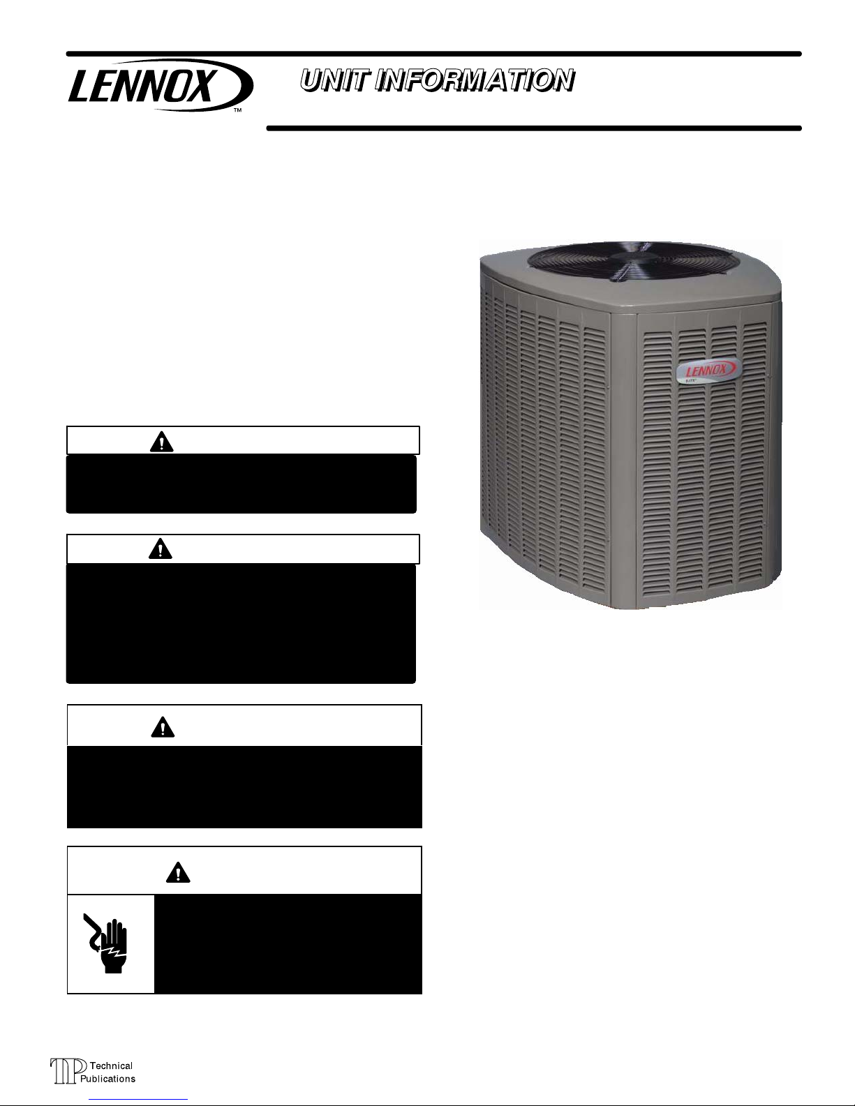
XP14 SERIES UNITS
The XP14 is a high efficiency residential split−system heat
pump unit, which features a scroll compressor and
HFC−410A refrigerant. XP14 units are available in sizes
ranging from 1 1/2 through 5 tons. The series is designed
for use with an indoor unit with an expansion valve approved for HFC−410A. This manual is divided into sections
which discuss the major components, refrigerant system,
charging procedure, maintenance and operation sequence.
Information contained in this manual is intended for use by
qualified service technicians only. All specifications are
subject to change.
IMPORTANT
Operating pressures of this HFC−410A unit are
higher than pressures in HCFC−22 units. Always
use service equipment rated for HFC−410A.
WARNING
Warranty will be voided if covered equipment is removed from original installation site. Warranty will
not cover damage or defect resulting from:
Flood, wind, lightning, or installation and operation in a corrosive atmosphere (chlorine, fluorine,
salt, recycled waste water, urine, fertilizers, or other damaging chemicals).
WARNING
Improper installation, adjustment, alteration, service
or maintenance can cause property damage, personal injury or loss of life. Installation and service must
be performed by a qualified installer or service
agency.
WARNING
Electric shock hazard. Can cause injury
or death. Before attempting to perform
any service or maintenance, turn the
electrical power to unit OFF at disconnect switch(es). Unit may have multiple
power supplies.
TABLE OF CONTENTS
Specifications / Electrical Page 2. . . . . . . . . . . . .
I Unit Information Page 3. . . . . . . . . . . . . . . . . . . .
II Unit Components Page 3. . . . . . . . . . . . . . . . . .
III Refrigerant System Page 13. . . . . . . . . . . . . . . .
IV Charging Page 15. . . . . . . . . . . . . . . . . . . . . . . . .
V Service and Recovery Page 20. . . . . . . . . . . . . .
VI Maintenance Page 21. . . . . . . . . . . . . . . . . . . . . .
VII Wiring Diagram Page 22. . . . . . . . . . . . . . . . . . .
Page 2
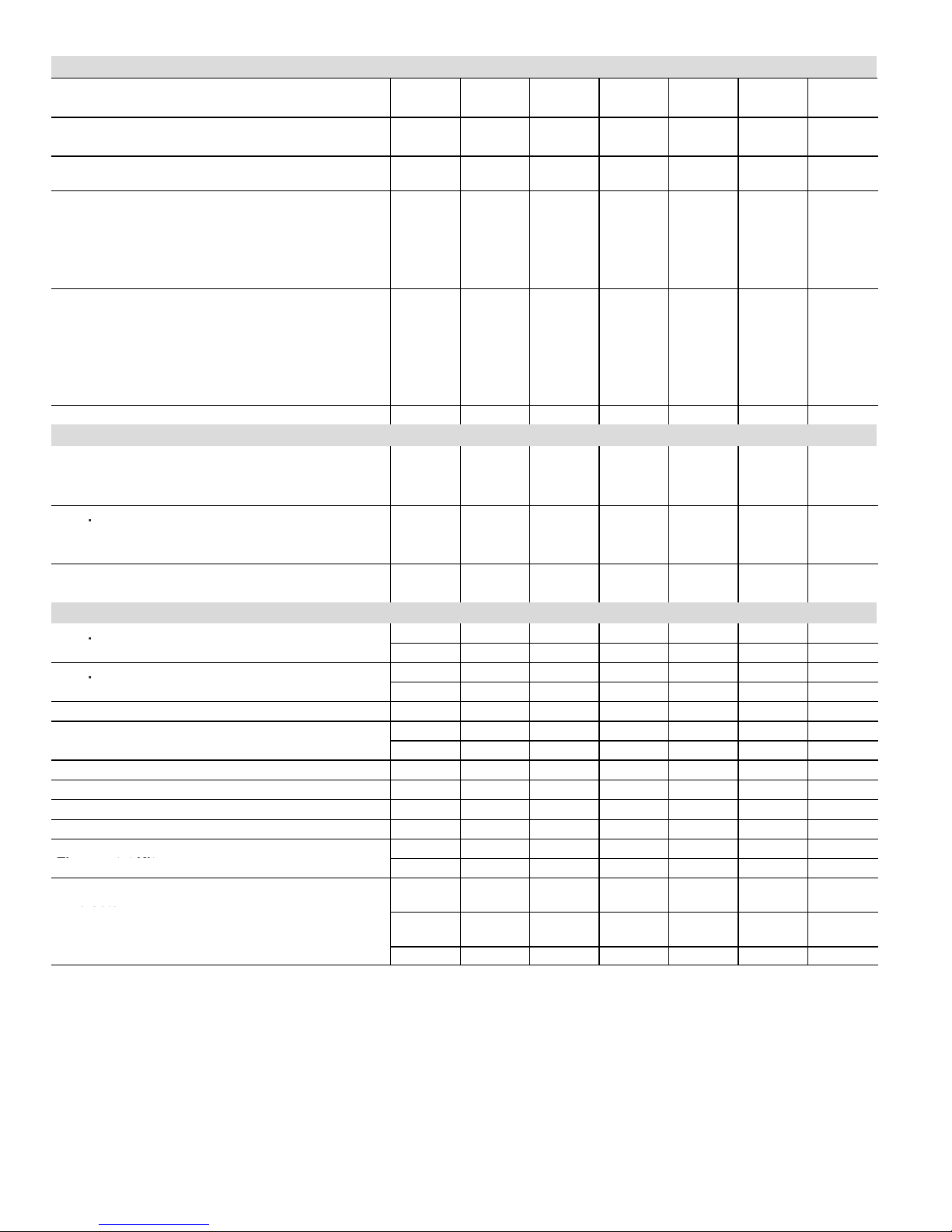
SPECIFICATIONS
General
Model No. XP14−018 XP14−024 XP14−030 XP14−036 XP14−042 XP14−048 XP14−060
Data
Nominal Tonnage 1.5
2 2.5 3 3.5 4 5
Connections
Liquid line o.d. − in. 3/8 3/8 3/8 3/8 3/8 3/8 3/8
(sweat)
Vapor line o.d. − in. 3/4
3/4 3/4 7/8 7/8 7/8 1-1/8
1
Refrigerant HFC−410A charge furnished 8 lbs.
4 oz.
8 lbs.
0 oz.
7 lbs.
2 oz.
9 lbs.
12 oz.
12 lbs.
7 oz.
12 lbs.
10 oz.
16 lbs.
0 oz.
Outdoor
Net face area
Outer coil 13.30 13.30 15.21 19.39 24.93 24.93 29.09
Coil sq. ft.
Inner coil 12.60
12.60 14.50 18.77 24.13 24.13 28.16
Tube diameter − in. 5/16 5/16 5/16 5/16 5/16 5/16 5/16
No. of rows 2 2 2 2 2 2 2
Fins per inch 22 22 22 22 22 22 22
Outdoor
Diameter − in. 18 18 18 26 26 26 26
Fan
No. of Blades 3
3 3 4 4 4 4
Motor hp 1/10 1/10 1/10 1/3 1/3 1/3 1/3
Cfm 2165 2165 2232 4090 4347 4347 4550
Rpm 1015 1015 1035 844 843 843 830
Watts 171 171 165 299 299 299 307
Shipping Data − lbs. 1 package 194 194 205 263 317 319 345
ELECTRICAL DATA
Line voltage data − 60 hz − 1ph 208/230V 208/230V 208/230V 208/230V 208/230V 208/230V 208/230V
2
Maximum overcurrent protection (amps) 20 30 30 30 40 50 60
3
Minimum circuit ampacity 11.9 17.5 17.0 19.4 24.2 29 34.8
Compressor
Rated Load Amps
8.97 13.46 13.1 14.1 17.94 21.79 26.41
p
Locked Rotor Amps
48 58 64 77 112 117 134
Power Factor
0.96 0.98 0.98 0.99 0.94 0.95 0.98
Outdoor
Full Load Amps
0.70 0.70 0.70 1.8 1.8 1.8 1.8
Fan Motor
Locked Rotor Amps
1.4
1.4 1.4 2.9 2.9 2.9 2.9
OPTIONAL ACCESSORIES − must be ordered extra
Compressor Crankcase Heater
93M04
p
Factory
Compressor Hard Start Kit
10J42
p
81J69
Compressor Low Ambient Cut−Off 45F08
Freezestat
3/8 in. tubing 93G35
5/8 in. tubing 50A93
Indoor Blower Off Delay Relay 58M81
4
Low Ambient Kit 54M89
Mild Weather Kit 33M07
Monitor Kit − Service Light 76F53
Outdoor
Thermostat 56A87
Thermostat Kit
Mounting Box 31461
Refrigerant
Line Sets
L15−41−20
L15−41−30
L15−41−40
L15−41−50
e Sets
L15−65−30 L15−65−40
L15−65−50
Field Fabricate
NOTE − Extremes of operating range are plus 10% and minus 5% of line voltage.
1
Refrigerant charge sufficient for 15 ft. length of refrigerant lines.
2
HACR type circuit breaker or fuse.
3
Refer to National or Canadian Electrical Code manual to determine wire, fuse and disconnect size requirements.
4
Crankcase Heater and Freezestat are recommended with Low Ambient Kit.
Page 3
I − UNIT INFORMATION
ELECTROSTATIC DISCHARGE (ESD)
Precautions and Procedures
CAUTION
Electrostatic discharge can affect electronic
components. Take precautions during unit installation and service to protect the unit’s electronic
controls. Precautions will help to avoid control
exposure to electrostatic discharge by putting
the unit, the control and the technician at the
same electrostatic potential. Neutralize electrostatic charge by touching hand and all tools on an
unpainted unit surface before performing any
service procedure.
All major components (indoor blower and coil) must be
matched according to Lennox recommendations for the
compressor to be covered under warranty. Refer to the Engineering Handbook for approved system matchups. A
misapplied system will cause erratic operation and can result in early compressor failure.
IMPORTANT
This unit must be matched with an indoor coil as
specified in Lennox’ Engineering Handbook.
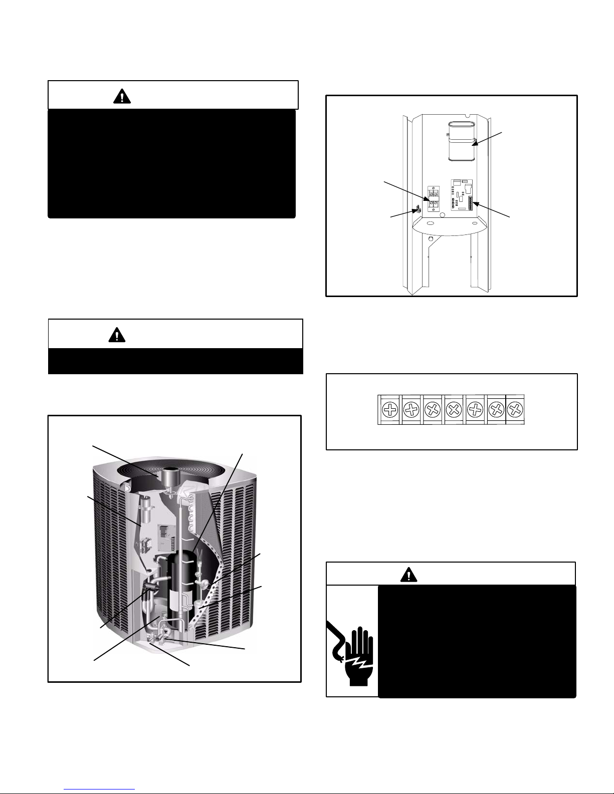
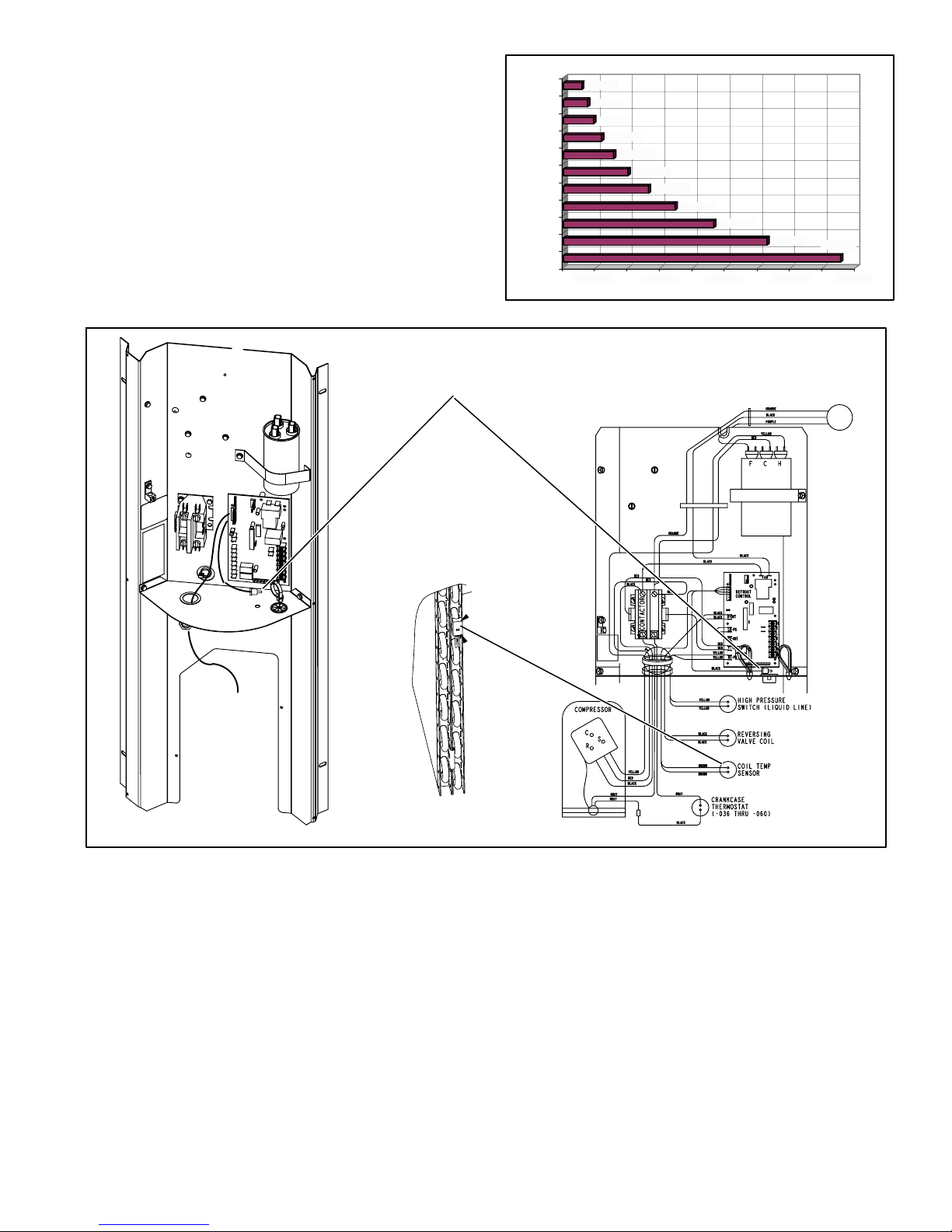
II − UNIT COMPONENTS
Unit components are illustrated in figure 1.
XP14 UNIT COMPONENTS
FIGURE 1
OUTDOOR FAN
COMPRESSOR
HIGH PRESSURE
SWITCH
REVERSING
VALV E
FILTER
DRIER
CONTROL
BOX
EXPANSION
VALV E
VAPOR LINE
SERVICE
VALV E
LIQUID LINE
SERVICE
VALV E
A − Control Box (Figure 2)
XP14 units are not equipped with a 24V transformer. All 24
VAC controls are powered by the indoor unit. Refer to wiring diagram.
FIGURE 2
DUAL CAPACITOR
(C12)
COMPRESSOR
CONTACTOR
(K1)
SINGLE PHASE UNIT CONTROL BOX
GROUNDING
LUG
DEFROST
CONTROL
(A108)
Electrical openings are provided under the control box cover. Field thermostat wiring is made to a 24V terminal strip
located on the defrost control board located in the control
box. See figure 2.
24V THERMOSTAT TERMINAL STRIP
FIGURE 3
W1 C L R O Y1
*Y2
*not used
1 − Compressor Contactor K1
The compressor is energized by a contactor located in the
control box. See figure 2. Single−pole contactors are used
in all XP14 series units. K1 is energized through the defrost control by the indoor thermostat terminal Y1 (24V)
when thermostat demand is present.
DANGER
Electric Shock Hazard.
May cause injury or death.
Line voltage is present at all components when unit is not in operation on
units with single pole contactors.
Disconnect all remote electrical power
supplies before opening unit panel.
Unit may have multiple power supplies.
Page 4
2 − Dual Capacitor C12
The compressor and fan in XP14 series units use permanent
split capacitor motors. The capacitor is located inside the unit
control box (see figure 2). A single dual" capacitor (C12) is
used for both the fan motor and the compressor (see unit wiring diagram). The fan side and the compressor side of the capacitor have different MFD ratings. See side of capacitor for
ratings.
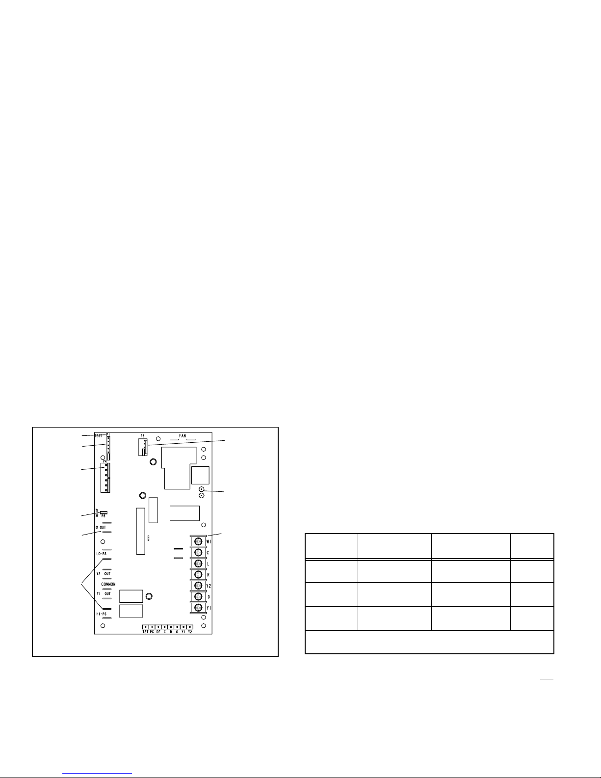
3 − Defrost System (CMC1)
The demand defrost control measures differential temperatures to detect when the system is performing poorly because of ice build−up on the outdoor coil. The controller
self−calibrates" when the defrost system starts and after
each system defrost cycle. The defrost control components are shown in figure 4.
The control monitors ambient temperature, outdoor coil
temperature, and total run time to determine when a defrost cycle is required. The coil temperature probe is designed with a spring clip to allow mounting to the outside
coil tubing. The location of the coil sensor is important for
proper defrost operation.
NOTE − The demand defrost control accurately measures
the performance of the system as frost accumulates on the
outdoor coil. This typically will translate into longer running
time between defrost cycles as more frost accumulates on
the outdoor coil before the board initiates defrost cycles.
Diagnostic LEDs
The state (Off, On, Flashing) of two LEDs on the defrost
board (DS1 [Red] and DS2 [Green]) indicate diagnostics
conditions that are described in table 2.
24V TERMINAL
STRIP
CONNECTIONS
DIAGNOSTIC
LEDS
PRESSURE
SWITCH CIRCUIT
CONNECTIONS
TEST PINS
NOTE − Component Locations Vary by Control Manufacturer.
Y2 not used on XP14
SENSOR
PLUG IN
(COIL & AM-
BIENT
SENSORS)
REVERSING
VALV E
DELAY
PINS
LOW
AMBIENT
THERMOSTAT
PINS
DEFROST
TERMINATION
PIN SETTINGS
FIGURE 4
Defrost Control Pressure Switch Connections
The unit’s automatic reset pressure switches (LO PS − S87
and HI PS − S4) are factory−wired into the defrost control on
the LO−PS and HI−PS terminals, respectively.
Low Pressure Switch (LO−PS)When the low pressure
switch trips, the defrost control will cycle off the compressor,
and the strike counter in the control will count one strike.
The low pressure switch is ignored under the following conditions:
during the defrost cycle and 90 seconds after the termina-
tion of defrost
when the average ambient sensor temperature is below
15° F (−9°C)
for 90 seconds following the start up of the compressor
during "test" mode
High Pressure Switch (HI−PS)When the high pressure
switch trips, the defrost control will cycle off the compressor,
and the strike counter in the control will count one strike.
Defrost Control Pressure Switch Settings
High Pressure (auto reset) − trip at 590 psig; reset at 418.
Low Pressure (auto reset) − trip at 25 psig; reset at 55.
5−Strike Lockout Feature
The internal control logic of the control counts the pressure
switch trips only while the Y1 (Input) line is active. If a pressure switch opens and closes four times during a Y1 (Input),
the control logic will reset the pressure switch trip counter to
zero at the end of the Y1 (Input). If the pressure switch
opens for a fifth time during the current Y1 (Input), the control will enter a lockout condition.
The 5−strike pressure switch lockout condition can be reset
by cycling OFF the 24−volt power to the control board or by
shorting the TEST pins between 1 and 2 seconds. All timer
functions (run times) will also be reset.
If a pressure switch opens while the Y1 Out line is engaged,
a 5−minute short cycle will occur after the switch closes.
Defrost System Sensors
Sensors connect to the defrost control through a field-replaceable harness assembly that plugs into the board.
Through the sensors, the control detects outdoor ambient
and coil temperature fault conditions. As the detected temperature changes, the resistance across the sensor
changes. Figure 5 shows how the resistance varies as the
temperature changes for both type of sensors. Sensor resistance values can be checked by ohming across pins
shown in table 1.
TABLE 1
Sensor
Temperature
Range °F (°C)
Resistance values
range (ohms)
Pins/Wire
Color
Outdoor
(Ambient)
−35 (−37) to 120
(48)
280,000 to 3750 3 & 4
(Black)
Coil −35 (−37) to 120
(48)
280,000 to 3750 5 & 6
(Brown)
Discharge (if
applicable)
24 (−4) to 350
(176)
41,000 to 103 1 & 2
(Yellow)
Note: Sensor resistance decreases as sensed temperature increases
(see figure5).
NOTE − When checking the ohms across a sensor, be
aware that a sensor showing a resistance value that is not
within the range shown in table 1, may be performing as designed. However, if a shorted or open circuit is detected,
then the sensor may be faulty and the sensor harness will
needs to be replaced.
Page 5
Coil SensorThe coil temperature sensor (shown in figure 6) considers outdoor temperatures below −35°F (−37°C)
or above 120°F (48°C) as a fault. If the coil temperature
sensor is detected as being open, shorted or out of the temperature range of the sensor, the defrost control will not perform demand or time/temperature defrost operation and
will display the appropriate fault code. Heating and cooling
operation will be allowed in this fault condition.
Ambient and Coil Sensor
RESISTANCE (OHMS)
TEMPERATURE (ºF)
5750
7450
9275
11775
15425
19975
26200
34375
46275
62700
100
90
80
70
60
50
40
30
20
10
0
10000 30000 50000 70000 90000
85300
FIGURE 5
COIL SENSOR
−
Clip coil temperature sensor from the defrost control on the bend shown − 6th
bend up. Apply grease between bend
and sensor.
AMBIENT
SENSOR
FIGURE 6
Ambient SensorThe ambient sensor (shown in figure 6)
considers outdoor temperatures below −35°F (−37°C) or
above 120°F (48°C) as a fault. If the ambient sensor is detected as being open, shorted or out of the temperature
range of the sensor, the control will not perform demand defrost operation. The control will revert to time/temperature
defrost operation and will display the appropriate fault
code. Heating and cooling operation will be allowed in this
fault condition.
NOTE − Within a single room thermostat demand, if
5−strikes occur, the control will lockout the unit. Defrost control 24 volt power R" must be cycled OFF" or the TEST"
pins on the control must be shorted between 1 to 2 seconds
to reset the control.
Defrost Temperature Termination Shunt (Jumper)
PinsThe defrost control selections are: 50, 70, 90, and
100°F (10, 21, 32 and 38°C). The shunt termination pin is
factory set at 50°F (10°C). If the temperature shunt is not
installed, the default termination temperature is 90°F
(32°C).
Delay Mode
The defrost control has a field−selectable function to reduce
occasional sounds that may occur while the unit is cycling in
and out of the defrost mode. When a jumper is installed on
the DELAY pins, the compressor will be cycled off for 30
seconds going in and out of the defrost mode. Units are
shipped with jumper installed on DELAY pins.

Page 6
NOTE − The 30 second off cycle is NOT functional when
jumpering the TEST pins.
Operational Description
The defrost control has three basic operational modes:
normal, calibration, and defrost.
Normal ModeThe demand defrost control monitors the
O line, to determine the system operating mode (heat/cool),
outdoor ambient temperature, coil temperature (outdoor
coil) and compressor run time to determine when a defrost
cycle is required.
Calibration ModeThe control is considered uncalibrated when power is applied to the control, after cool mode
operation, or if the coil temperature exceeds the termination temperature when it is in heat mode.
Calibration of the control occurs after a defrost cycle to ensure that there is no ice on the coil. During calibration, the
temperature of both the coil and the ambient sensor are
measured to establish the temperature differential which is
required to allow a defrost cycle. See figure 8 for calibration
mode sequence.
Defrost ModeThe following paragraphs provide a detailed description of the defrost system operation.
Detailed Defrost System Operation
Defrost CyclesThe demand defrost control initiates a
defrost cycle based on either frost detection or time.
Frost DetectionIf the compressor runs longer than 34
minutes and the actual difference between the clear
coil and frosted coil temperatures exceeds the maximum difference allowed by the control, a defrost cycle
will be initiated.
TimeIf 6 hours of heating mode compressor run time has
elapsed since the last defrost cycle while the coil temperature remains below 35°F (2°C), the demand defrost control will initiate a defrost cycle.
ActuationWhen the reversing valve is de−energized, the
Y1 circuit is energized, and the coil temperature is below
35°F (2°C), the control logs the compressor run time. If the
control is not calibrated, a defrost cycle will be initiated after
34 minutes of heating mode compressor run time. The control will attempt to self−calibrate after this (and all other) defrost cycle(s).
Calibration success depends on stable system temperatures during the 20−minute calibration period. If the control
fails to calibrate, another defrost cycle will be initiated after
45 minutes (90 minutes −1 to −4 boards) of heating mode
compressor run time. Once the defrost control is calibrated,
it initiates a demand defrost cycle when the difference between the clear coil and frosted coil temperatures exceeds
the maximum difference allowed by the control OR after 6
hours of heating mode compressor run time has been
logged since the last defrost cycle.
NOTE − If ambient or coil fault is detected, the control will not
execute the TEST" mode.
TerminationThe defrost cycle ends when the coil temperature exceeds the termination temperature or after 14
minutes of defrost operation. If the defrost is terminated by
the 14−minute timer, another defrost cycle will be initiated
after 34 minutes of run time.
Test ModeWhen Y1 is energized and 24V power is being
applied to the control, a test cycle can be initiated by placing
the termination temperature jumper across the Test" pins
for 2 to 5 seconds. If the jumper remains across the Test"
pins longer than 5 seconds, the control will ignore the test
pins and revert to normal operation. The jumper will initiate
one cycle per test.
Enter the TEST" mode by placing a shunt (jumper) across
the TEST" pins on the control after power−up. (The TEST"
pins are ignored and the test function is locked out if the
shunt is applied on the TEST" pins before power−up). Control timings are reduced, the low−pressure switch is ignored
and the control will clear any active lockout condition.
Each test pin shorting will result in one test event. For
each TEST" the shunt (jumper) must be removed for at
least 1 second and reapplied. Refer Defrost Control Pin Operationto flow chart (figure 7) for TEST" operation.
Note: The Y1 input must be active (ON) and the O" room
thermostat terminal into board must be inactive.
Defrost Control Diagnostics
See table 2 to determine defrost control operational conditions and to diagnose cause and solution to problems.
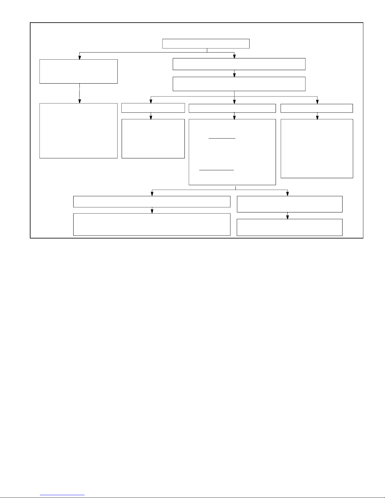
Page 7
If in COOLING Mode If in HEATING Mode If in DEFROST Mode
Short test pins for longer
than 1 second but less than
2 seconds
Short test pins for more than 2 seconds
Y1 Active (0" line inactive)
Test pin short REMAINS in place for more than 5 seconds Test pins short REMOVED before a
maximum of 5 seconds
Clear any short cycle lockout
and 5 strike fault lockout
function, if applicable. No
other functions will be
executed and unit will
continue in the mode it was
operating.
No further test mode
operation will be
executed until the test
short is removed and
reapplied.
The control will check for ambient
and coil faults (open or shorted).
If a fault exists
, the unit will
remain in Heat Mode and no
further test mode operation will
be executed until the test short is
removed and re applied. If
no fault exists
and ambient
temperature is below 35ºF, the
unit will go into Defrost mode.
The unit will terminate
defrost and enter Heat
Mode uncalibrated with
defrost timer set for 34
minute test. No further
test mode operation will
be executed until the test
short is removed and
reapplied.
Clear any short cycle lockout and 5 strike
fault lockout function, if applicable.
The unit will return to Heat mode uncalibrated with defrost
timer set for 34 minutes. No further test mode operation will
be executed until the test short is removed and re applied.
The unit will remain in Defrost mode
until termination on time or temperature
FIGURE 7
Defrost Control Pin Operation
 Loading...