

Lennox XP14 Elite Series, Elite XP14-018, Elite XP14-024, Elite XP14-030, Elite XP14-036 Installation Instructions Manual
...
INSTALLATION
2010 Lennox Industries Inc.
Dallas, Texas, USA
RETAIN THESE INSTRUCTIONS
FOR FUTURE REFERENCE
WARNING
Improper installation, adjustment, alteration,
service or maintenance can cause personal injury,
loss of life, or damage to property.
Installation and service must be performed by a
qualified installer or service agency.
CAUTION
Physical contact with metal edges and corners
while applying excessive force or rapid motion can
result in personal injury. Be aware of, and use
caution when working near these areas during
installation or while servicing this equipment.
IMPORTANT
The Clean Air Act of 1990 bans the intentional
venting of refrigerant (CFCs, HFCs, and HCFCs) as
of July 1, 1992. Approved methods of recovery,
recycling or reclaiming must be followed. Fines
and/or incarceration may be levied for
noncompliance.
IMPORTANT
This unit must be matched with an indoor coil as
specified in Lennox’ Engineering Handbook.
Coils previously charged with HCFC−22 must be
flushed.
INSTRUCTIONS
XP14 Elite® Series Units
HEAT PUMP UNITS
505,244M
03/10
Supersedes 10/09
Table of Contents
XP14 Outdoor Unit 1. . . . . . . . . . . . . . . . . . . . . . . . . . . .
Shipping and Packing List 1. . . . . . . . . . . . . . . . . . . . . .
Unit Dimensions and Parts Arrangement 2. . . . . . . . .
General Information 3. . . . . . . . . . . . . . . . . . . . . . . . . . .
Setting the Unit 3. . . . . . . . . . . . . . . . . . . . . . . . . . . . . . .
Removing Panels 5. . . . . . . . . . . . . . . . . . . . . . . . . . . . .
Electrical 6. . . . . . . . . . . . . . . . . . . . . . . . . . . . . . . . . . . . .
Refrigerant Piping 8. . . . . . . . . . . . . . . . . . . . . . . . . . . . .
Flushing Existing Line Set and Indoor Coil 10. . . . . . . .
Refrigerant Metering Device 11. . . . . . . . . . . . . . . . . . . .
Manifold Gauge Set 12. . . . . . . . . . . . . . . . . . . . . . . . . . .
Service Valves 12. . . . . . . . . . . . . . . . . . . . . . . . . . . . . . . .
Leak Testing 13. . . . . . . . . . . . . . . . . . . . . . . . . . . . . . . . . .
Evacuation 13. . . . . . . . . . . . . . . . . . . . . . . . . . . . . . . . . . .
Start−Up 14. . . . . . . . . . . . . . . . . . . . . . . . . . . . . . . . . . . . . .
Refrigerant Charge 14. . . . . . . . . . . . . . . . . . . . . . . . . . . .
Check Indoor Airflow before Charging 14. . . . . . . . . . . .
Setup for Checking and Adding Charge 15. . . . . . . . . .
Weigh in Charge 15. . . . . . . . . . . . . . . . . . . . . . . . . . . . . .
Subcooling Charge 15. . . . . . . . . . . . . . . . . . . . . . . . . . . .
Defrost System 19. . . . . . . . . . . . . . . . . . . . . . . . . . . . . . .
Maintenance 24. . . . . . . . . . . . . . . . . . . . . . . . . . . . . . . . . .
User Information 24. . . . . . . . . . . . . . . . . . . . . . . . . . . . . .
Start-up and Performance Checklist 26. . . . . . . . . . . . . .
XP14 Outdoor Unit
The XP14 outdoor unit uses HFC−410A HFC refrigerant.
This unit must be installed with a matching indoor blower
coil and line set as outlined in the Lennox Engineering
Handbook. Elite® Series XP14 outdoor units are designed
for use in check expansion valve (CTXV) systems only and
are not to be used with other refrigerant flow control
devices. An expansion valve approved for use with
HFC−410A must be ordered separately and installed prior
to operating the unit.
Shipping and Packing List
1 − Assembled XP14 outdoor unit
Check the unit components for shipping damage. If you
find any damage, immediately contact the last carrier.
Litho U.S.A.
03/10 505,244M
*2P0310* *P505244M*
Page 1
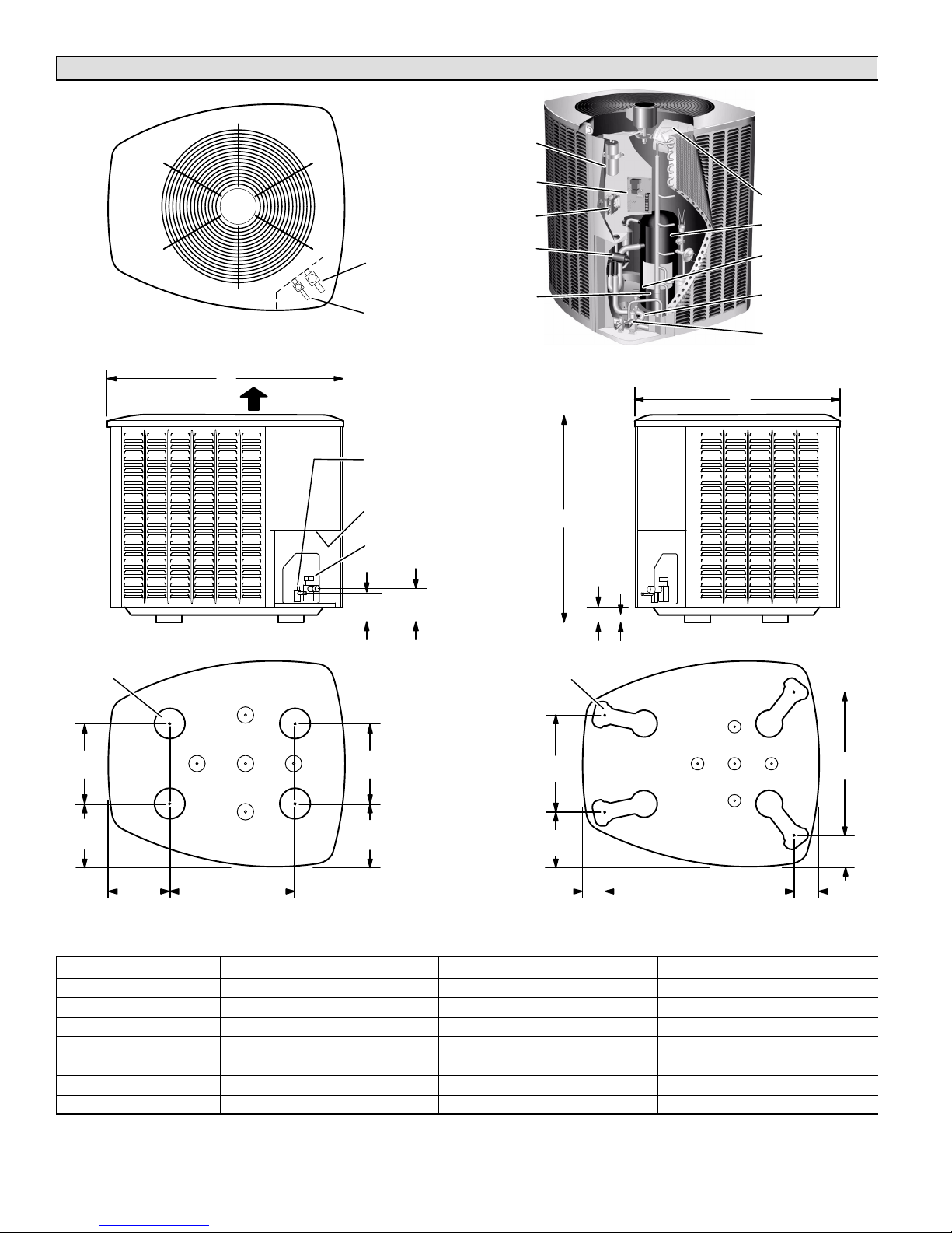
Unit Dimensions − Inches (mm) and Parts Arrangement
RUN
CAPACITOR
DEFROST
BOARD
CONTACTOR
REVERSING
VALV E
FILTER DRIER/
LIQUID LINE
CONNECTIONS
TOP VIEW
C
DISCHARGE AIR
SUCTION LINE
CONNECTION
LIQUID LINE
CONNECTION
LIQUID LINE
CONNECTION
ELECTRICAL
INLETS
VAPOR LINE
CONNECTION
108)
4−3/4
(121)
4−1/4(
PARTS ARRANGEMENT
A
2 (51)
OUTDOOR FAN
COMPRESSOR
HIGH PRESSURE
SWITCH
VAPOR LINE
VAPOR VALVE AND
GAUGE PORT/SUCTION
LINE CONNECTIONS
B
SIDE VIEW
UNIT SUPPORT
FEET
8−1/2
(216)
8−3/4
(222)
5−1/2
(140)
13−1/2
(343)
XP14−018 TO −030 BASE SECTION
9−1/2
(241)
8−1/4
(210)
UNIT SUPPORT
FEET
16−7/8
(429)
8−3/4
(222)
3−1/8
(79)
1 (25)
XP14−036 TO −060 BASE WITH
ELONGATED LEGS
Model No. A B C
XP14−018 31 (787) 27 (686) 28 (711)
XP14−024 31 (787) 27 (686) 28 (711)
XP14−030 35 (889) 27 (686) 28 (711)
XP14−036 31 (787) 35 1/2 (902) 39 1/2 (1003)
XP14−042 39 (991) 35 1/2 (902) 39 1/2 (1003)
XP14−048 39 (991) 35 1/2 (902) 39 1/2 (1003)
XP14−060 45 (1143) 35 1/2 (902) 39 1/2 (1003)
SIDE VIEW
30−3/4
(781)
26−7/8
(683)
3−3/4
(95)
4−5/8
(117)
505244M 10/09
Page 2
WARNING
Product contains fiberglass wool.
Disturbing the insulation of this product during
installation, maintenance, or repair will expose you
to fiberglass wool. Breathing this may cause lung
cancer. (Fiberglass wool is know to the State of
California to cause cancer.) Fiberglass wool may
also cause respiratory, skin and eye irritation.
To reduce exposure to this substance or for further
information, consult material safety data sheets
available from address show below, or contact your
supervisor.
Lennox Industries Inc., PO Box 79011, Dallas, TX
75379−9011
General Information
These instructions are intended as a general guide and do
not supersede local codes in any way. Consult authorities
having jurisdiction before installation.
When servicing or repairing HVAC components, ensure
the fasteners are appropriately tightened. Table 1 shows
torque values for fasteners.
Table 1. Torque Requirements
Part Recommended Torque
Service valve cap 8 ft.− lb. 11 NM
Sheet metal screws 16 in.− lb. 2 NM
Machine screws #8 16 in.− lb. 2 NM
Compressor bolts 90 in.− lb. 10 NM
Gauge port seal cap 8 ft.− lb. 11 NM
4. Locate the unit so prevailing winter winds will not blow
into the coil.
5. Locate unit away from overhanging roof lines which
would allow water or ice to drop on, or in front of, coil
or into unit.
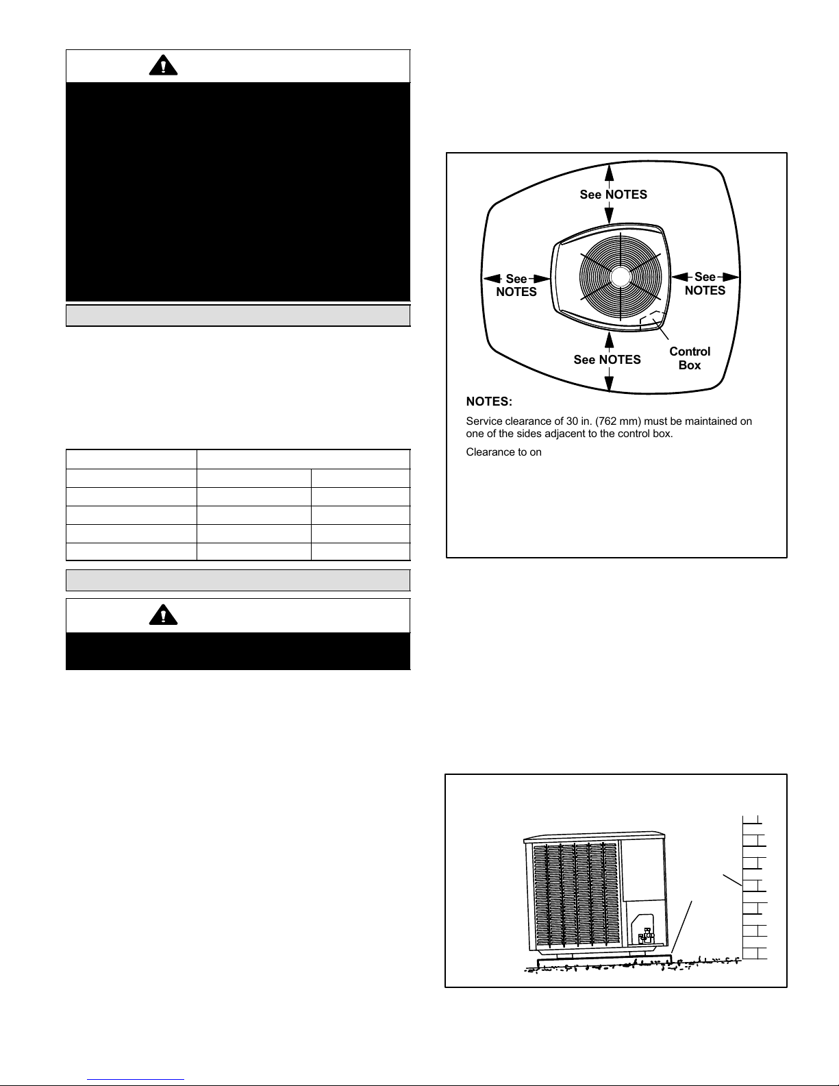
See NOTES
See
NOTES
See NOTES
NOTES:
Service clearance of 30 in. (762 mm) must be maintained on
one of the sides adjacent to the control box.
Clearance to one of the other three sides must be 36 in. (914
mm)
Clearance to one of the remaining two sides may be 12 in. (305
mm) and the final side may be 6 in. (152 mm).
A clearance of 24 in. (610 mm) must be maintained between
two units.
48 in. (1219 mm) clearance required on top of unit.
See
NOTES
Control
Box
Setting the Unit
CAUTION
In order to avoid injury, take proper precaution when
lifting heavy objects.
Outdoor units operate under a wide range of weather
conditions; therefore, several factors must be considered
when positioning the outdoor unit.
Position the unit to allow adequate airflow and servicing
clearance. Maintain a minimum clearance of 24 inches
(610 mm) between multiple units as illustrated in figure 1
for installation clearances.
1. Place a sound-absorbing material, such as Isomode,
under the unit if it will be installed in a location or
position that will transmit sound or vibration to the
living area or adjacent buildings.
2. Install the unit high enough above ground or roof to
allow adequate drainage of defrost water and prevent
ice build-up.
3. In heavy snow areas, do not locate unit the where
snowdrifts will likely build. The unit base should be
elevated above the depth of average snows.
NOTE - Elevation of the unit may be accomplished by
constructing a frame using suitable materials. If a
support frame is constructed, it must not block drain
holes in unit base.
Figure 1. Installation Clearances
SLAB MOUNTING
When installing unit at grade level, the top of the slab
should be high enough above grade so that water from
higher ground will not collect around the unit. The slab
should have a slope tolerance away from the building of 2
degrees or 2 inches per 5 feet (50 mm per 1500 mm) to
prevent ice build-up under the unit during a defrost cycle.
NOTE − If necessary for stability, anchor unit to slab as
described in Stabilizing Unit on Uneven Surfaces on page
4.
INSTALL UNIT LEVEL OR, IF ON A SLOPE, MAINTAIN SLOPE
TOLERANCE OF 2 DEGREES (OR 2 INCHES PER 5 FEET
[50 MM PER 1.5 M]) AWAY FROM BUILDING STRUCTURE.
BUILDING
STRUCTURE
MOUNTING
SLAB
GROUND LEVEL
Figure 2. Slab Mounting Options
Page 3
XP14 SERIES
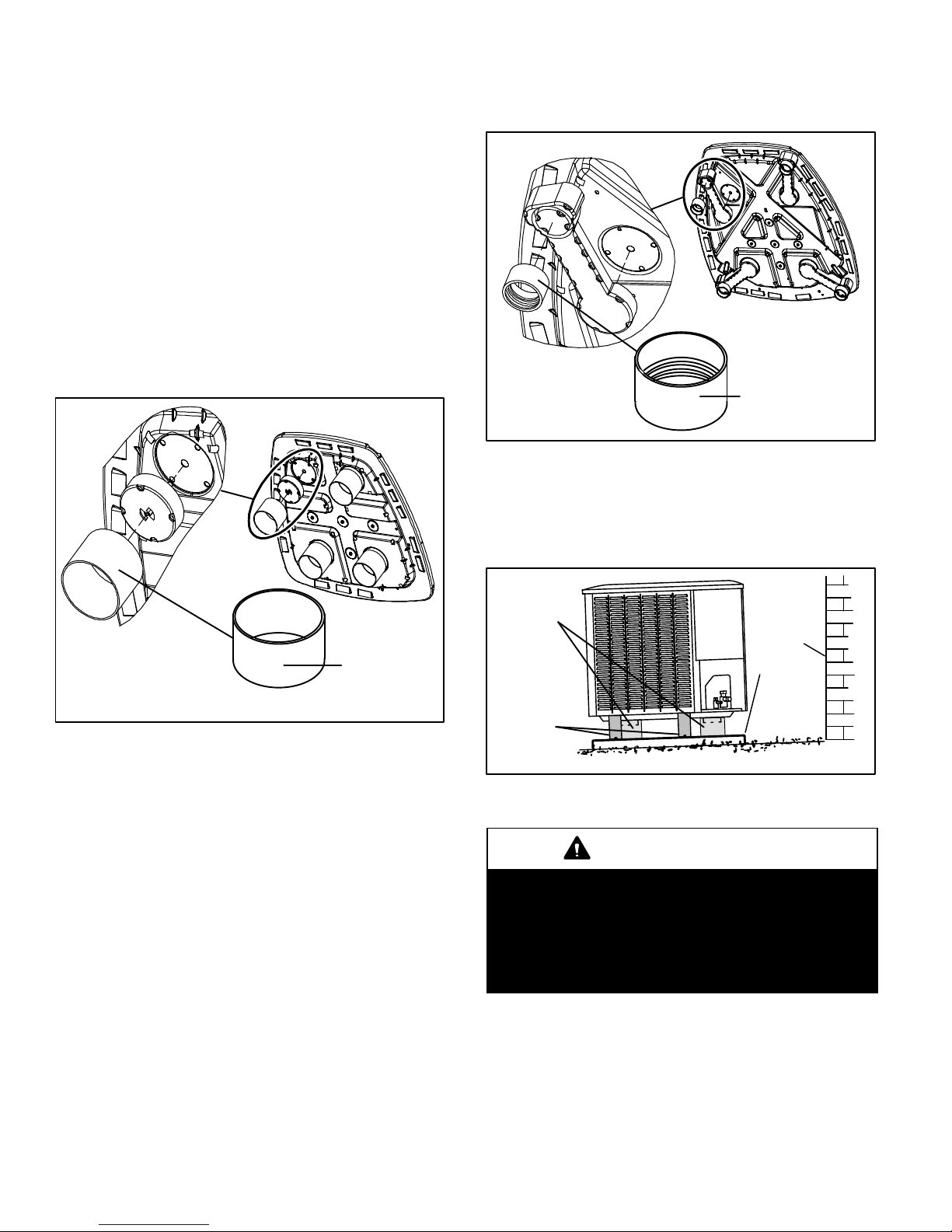
ELEVATING THE UNIT (SMALL−BASE UNITS)
If additional elevation is necessary, raise the unit by
extending the length of the unit support feet. This may be
done by cutting four equal true−cut lengths of Schedule
(SCH) 40, 4" (101.6mm) piping to the height required as
illustrated in figure 3.
NOTE − Keep the height of extenders short enough to
ensure a sturdy installation. If it is necessary to extend
further, consider a different type of field−fabricated
framework that is sturdy enough for greater heights.
The inside diameter of the 4" (101.6mm) piping is
approximately 0.25" (6.35mm) greater than the
pre−installed feet on the unit. Devise a shim that will take up
the space and hold the extenders onto the feet during this
procedure. Small strips of 0.125" (3.175mm) thick
adhesive foam may be used. One or two small 1"
(25.4mm) square strips should be adequate to hold the
extender in place.
Base
NOTE − Keep the height of extenders short enough to
ensure a sturdy installation. If it is necessary to extend
further, consider a different type of field−fabricated
framework that is sturdy enough for greater heights.
Base
Leg Detail
2" (50.8mm)
SCH 40
Female Threaded
Adapter
Figure 4. Elevated Slab Mounting using Feet
Extenders (Larger Base Units)
STABILIZING UNIT ON UNEVEN SURFACES
To help stabilize an outdoor unit, some installations may
require strapping the unit to the pad using brackets and
anchors commonly available in the marketplace.
Leg Detail
4" (101.6mm)
SCH 40 Piping
Figure 3. Elevated Slab Mounting using Feet
Extenders (Small Base Units)
ELEVATING THE UNIT (LARGER−BASE UNITS)
Unlike the small−base units which use round feet, the
larger−base units are outfitted with elongated feet as
illustrated in figure 4. which uses a similar method for
elevating the unit height.
If additional elevation is necessary, raise the unit by
extending the length of the unit support feet. This may be
done with 2" SCH 40 female threaded adapter. The
specified coupling will fit snuggly into the recess portion of
the feet. Use additional 2" SCH 40 male threaded adaptors
which can be threaded into the female threaded adaptors
to make additional adjustments to the level of the unit.
TYPICAL
INSTALLATION
WITH 3 TO 4 IN.
EXTENDERS
INSTALLED
IMPORTANT!
ALWAYS USE
STABILIZER
BRACKET ON
ELEVATED
INSTALLATIONS
STABILIZER
BRACKETS
GROUND LEVEL
BUILDING
STRUCTURE
MOUNTING
SLAB
Figure 5. Elevated Slab Mounting using Feet
Extenders
IMPORTANT
Unit Stabilizer Bracket Use (field−provided):
Always use stabilizers when unit is raised above the
factory height. (Elevated units could become
unstable in gusty wind conditions).
Stabilizers may be used on factory height units
when mounted on unstable or uneven surface.
505244M 10/09
Page 4
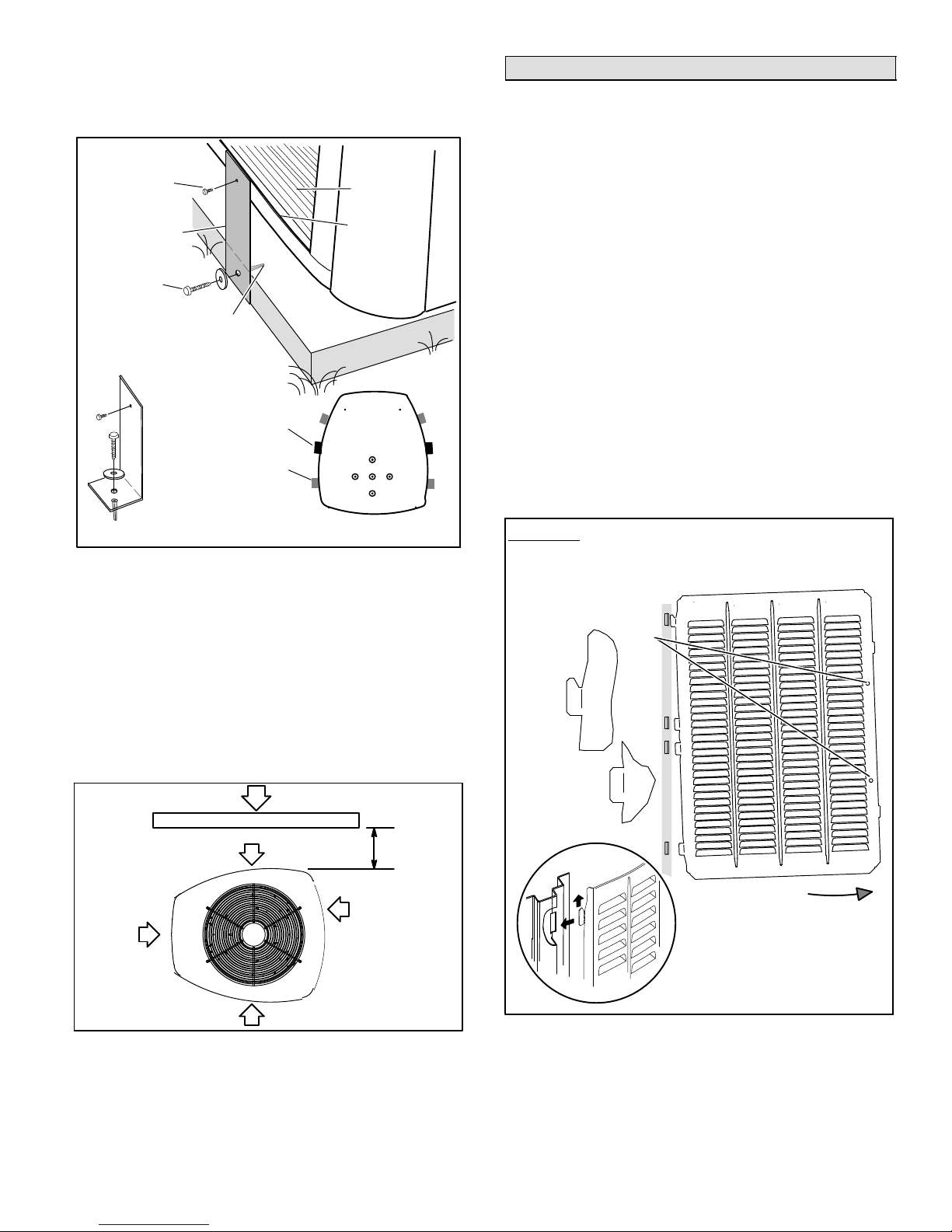
With unit positioned at installation site, remove two side
louvered panels to expose the unit base pan.
Install the
brackets as illustrated in figure 6 using conventional
practices; replace the panels after installation is complete.
#10 1/2" LONG
SELF−DRILLING SHEET
METAL SCREWS
STABILIZING BRACKET
(18 GAUGE METAL − 2"
WIDTH; HEIGHT AS
REQ’D)
#10 1−1/4" LONG HEX
HD SCREW &
FLATWASHER
PLASTIC ANCHOR − USE IF CONCRETE
(HOLE DRILL 1/4"); NOT IF PLASTIC SLAB
(HOLE DRILL 1/8").
Deck Top
Mounting
STABILIZING
BRACKET (18
GAUGE METAL − 2"
WIDTH; HEIGHT
AS REQ’D); BEND
TO FORM RIGHT
ANGLE
MINIMUM 1
PER SIDE
FOR EXTRA
STABILITY
COIL
BASE PAN
CORNER POST
Removing Panels
Remove the louvered panels as follows:
1. Remove two screws, allowing the panel to swing open
slightly as illustrated in figure 8.
2. Hold the panel firmly throughout this procedure.
Rotate bottom corner of panel away from hinge corner
post until lower three tabs clear the slots as illustrated
figure 8, Detail B .
3. Move panel down until lip of upper tab clears the top
slot in corner post as illustrated in figure 8, Detail A.
Position and Install PanelPosition the panel almost
parallel with the unit as illustrated in figure 9, Detail D on
page 6 with the screw side as close to the unit as possible.
Then, in a continuous motion:
slightly rotate and guide the lip of top tab inward as
illustrated in figure 8, Details A and C; then upward into
the top slot of the hinge corner post.
rotate panel to vertical to fully engage all tabs.
holding the panel’s hinged side firmly in place, close
the right−hand side of the panel, aligning the screw
holes.
When panel is correctly positioned and aligned, insert the
screws and tighten.
ONE BRACKET PER SIDE (MIN.); FOR EXTRA STABILITY,
2 BRACKETS PER SIDE, 2" FROM EACH CORNER.
Figure 6. Installing Stabilizer Brackets
(Slab Side Mounting)
ROOF MOUNTING
Install unit 6" (152 mm) above the roof surface to avoid ice
build−up around the unit. Locate the unit above a load
bearing wall or area of the roof that can adequately support
the unit. Consult local codes for rooftop applications.
If unit cannot be located away from prevailing winter winds,
construct a wind barrier sized at least the same height and
width as outdoor unit. Position barrier 24" (610 mm) from
the sides of the unit in direction of prevailing winds as
illustrated in figure 7.
prevailing winter winds
wind barrier
24"
inlet air
inlet air
(610 mm)
inlet air
IMPORTANT! Do not allow panels to hang on unit by top tab. Tab
is for alignment and not designed to support weight of panel.
Panel shown slightly rotated to allow top tab to exit (or enter) top
slot for removing (or installing) panel.
SCREW
HOLES
LIP
Detail
A
Detail
B
ROTATE IN THIS DIRECTION;
THEN DOWN TO REMOVE PANEL
inlet air
Figure 7. Rooftop Application with Wind Barrier
Detail C
Figure 8. Removing/Installing Louvered Panels
(Details A, B and C)
Page 5
XP14 SERIES
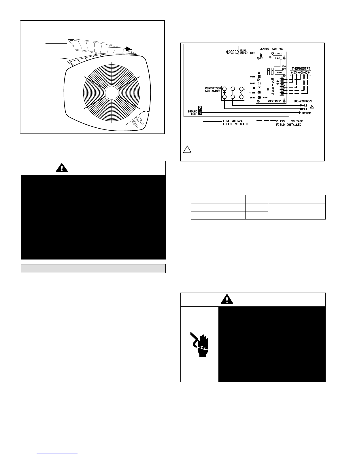
MAINTAIN MINIMUM PANEL ANGLE (AS CLOSE TO PARALLEL WITH THE UNIT
AS POSSIBLE) WHILE INSTALLING PANEL.
ANGLE MAY BE TOO
EXTREME
PREFERRED ANGLE
FOR INSTALLATION
HOLD DOOR FIRMLY TO THE HINGED
SIDE TO MAINTAIN
FULLY−ENGAGED TABS
Detail D
Figure 9. Removing/Installing Louvered Panels
(Detail D)
4. Units are approved for use only with copper
conductors. (A complete unit wiring diagram is
located inside the unit control box cover.)
WARNING! − ELECTRIC SHOCK HAZARD. Can cause INJURY or DEATH. Unit must be grounded in accordance with
national and local codes.
NOTE − For use with copper conductors only. Refer to unit
rating plate for minimum circuit ampacity and maximum overcurrent protection size.
CAUTION
To prevent personal injury, or damage to panels,
unit or structure, be sure to observe the following:
While installing or servicing this unit, carefully stow
all removed panels out of the way, so that the panels
will not cause injury to personnel, nor cause
damage to objects or structures nearby, nor will the
panels be subjected to damage (e.g., being bent or
scratched).
While handling or stowing the panels, consider any
weather conditions, especially windy conditions,
that may cause panels to be blown around and
battered.
Electrical
In the U.S.A., wiring must conform with current local codes
and the current National Electric Code (NEC). In Canada,
wiring must conform with current local codes and the current
Canadian Electrical Code (CEC).
Refer to the furnace or blower coil installation instructions
for additional wiring application diagrams and refer to unit
nameplate for minimum circuit ampacity and maximum
overcurrent protection size.
1. Install line voltage power supply to unit from a properly
sized unit disconnect switch.
2. Ground the unit at the unit disconnect switch or to
earth ground.
3. To facilitate conduit, a hole is provided in the bottom of
the control box. Connect conduit to the control box
using a proper conduit fitting.
Figure 10. Outdoor Unit Typical Field Wiring
NOTE − For proper voltages, select thermostat wire
gauge per the following chart:
Table 2. Wire Run Lengths
Wire run length AWG # Insulation type
less than 100’ (30m) 18
more than 100’ (30m) 16
color−coded, temperature
rating 35ºC minimum
5. Install room thermostat (ordered separately) on an
inside wall approximately in the center of the
conditioned area and 5 feet (1.5 m) from the floor. It
should not be installed on an outside wall or where it
can be affected by sunlight, drafts or vibrations.
6. Install low voltage wiring from outdoor to indoor unit
and from thermostat to indoor unit. See figures 11 and
12 on page 7.
NOTE − 24V, Class II circuit connections are made in the
low voltage junction box.)
WARNING
Electric Shock Hazard. Can cause
injury or death. Unit must be
grounded in accordance with national
and local codes.
Line voltage is present at all
components when unit is not in
operation on units with single-pole
contactors. Disconnect all remote
electric power supplies before
opening access panel. Unit may have
multiple power supplies.
505244M 10/09
Page 6
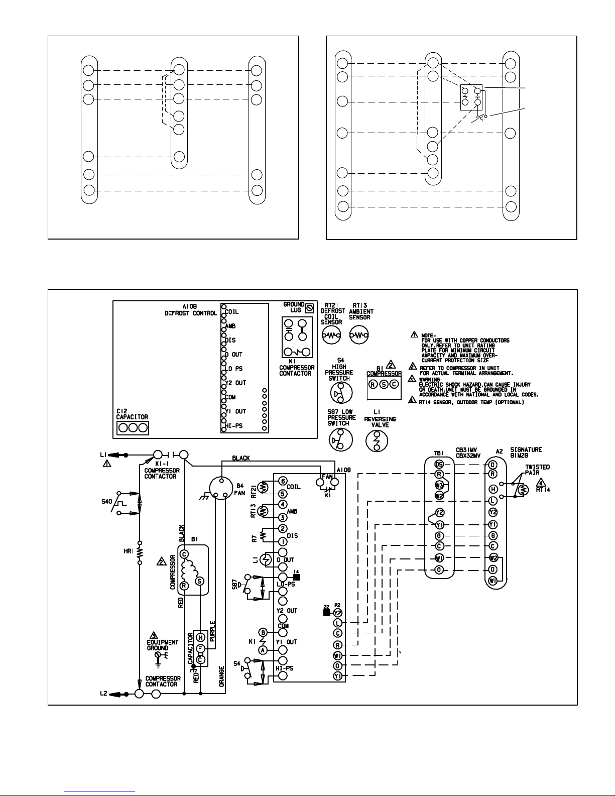
Thermostat Indoor Unit Outdoor Unit
24V power
R
common
C
1st-stage
W1
auxiliary heat
W3
indoor blower
G
reversing valve
O
compressor
Y1
(SOME CONNECTIONS MAY NOT APPLY. REFER TO SPECIFIC
THERMOSTAT AND INDOOR UNIT.)
W1
W2
R
C
G
24V power
common
1st-stage
auxiliary heat
R
C
W1
O
Y1
Thermostat Indoor Unit Outdoor Unit
24V power 24V power
R
common
C
emergency heat
E
1st-stage
W1
auxiliary heat
indoor blower
G
reversing valve
O
compressor
Y1
(SOME CONNECTIONS MAY NOT APPLY. REFER TO SPECIFIC
THERMOSTAT AND INDOOR UNIT.)
W1
W2
W3
R
common
C
1st-stage
auxiliary heat
G
R
C
W1
O
Y1
EMERGENCY
HEAT RELAY
OUTDOOR
THERMOSTAT
Figure 11. Outdoor Unit and Blower Unit Thermostat
Designations
Figure 12. Outdoor Unit and Blower Unit Thermostat
Designations (with Emergency Heat Relay)
Figure 13. Typical XP14 Wiring
Page 7
XP14 SERIES
Refrigerant Piping
IMPORTANT
The Clean Air Act of 1990 bans the intentional
venting of refrigerant (CFC’s, HFC’s, and HCFC’s)
as of July 1, 1992. Approved methods of recovery,
recycling or reclaiming must be followed. Fines
and/or incarceration may be levied for
noncompliance.
If the XP14 unit is being installed with a new indoor coil and
line set, the plumbing connections should be made as
outlined in this section. If an existing line set and/or indoor
coil is going to be used to complete the XP14 system, refer
to the following section that includes flushing procedures.
Field refrigerant piping consists of liquid and vapor lines
from the outdoor unit (sweat connections) to the indoor coil
(flare or sweat connections). Use Lennox L15 (sweat,
non-flare) series line sets as shown in table 3 or use
field-fabricated refrigerant lines. Refer to Refrigerant
Piping Guide (Corp. 9351−L9) for proper size, type, and
application of field−fabricated lines. Valve sizes are also
listed in table 3.
REFRIGERANT LINE CONNECTIONS − XP14
OUTDOOR UNIT MATCHED WITH NEW INDOOR
COIL AND LINE SET
If replacing an existing coil equipped with a liquid line
functioning as a metering orifice, replace the liquid line
prior to installing the XP14 unit. Line sets are described in
table 3.
Table 3. Refrigerant Line Sets
Valve Field
Model
−018
−024
−030
−036
−042
−048
−060
Connections
Liquid
Line
3/8 in.
(10 mm)
3/8 in.
(10 mm)
3/8 in.
(10 mm)
Vapor
Line
3/4 in
(19 mm)
7/8 in
(22 mm)
1−1/8 in.
(29 mm)
NOTE − When installing refrigerant lines, refer to Lennox
Refrigerant Piping Guide (Corp. 9351−L9) or Lennox
Technical Support Department Product Applications
Group for assistance. In addition, be sure to consider the
following points:
Recommended Line Set
Liquid
Line
3/8 in.
(10
mm)
3/8 in.
(10
mm)
3/8 in.
(10
mm)
Vapor
Line
3/4 in
(19 mm)
7/8 in
(22 mm)
1−1/8 in.
(29 mm)
L15
Line Sets
L15−41
15 ft. − 50 ft.
(4.6 m − 15 m)
L15−65
15 ft. − 50 ft.
(4.6 m − 15 m)
Field
Fabricated
Select line set diameters from table 3 to ensure that oil
returns to the compressor.
Units are designed for line sets of up to 50 feet (15 m);
for longer line sets, consult piping guidelines.
Size vertical vapor riser to maintain minimum velocity
at minimum capacity.
INSTALLING REFRIGERANT LINE
Pay close attention to line set isolation during installation of
any heat pump or a/c system. When properly isolated from
building structures (walls, ceilings. floors), the refrigerant
lines will not create unnecessary vibration and subsequent
noises. Also, consider the following when placing and
installing a high−efficiency outdoor unit:
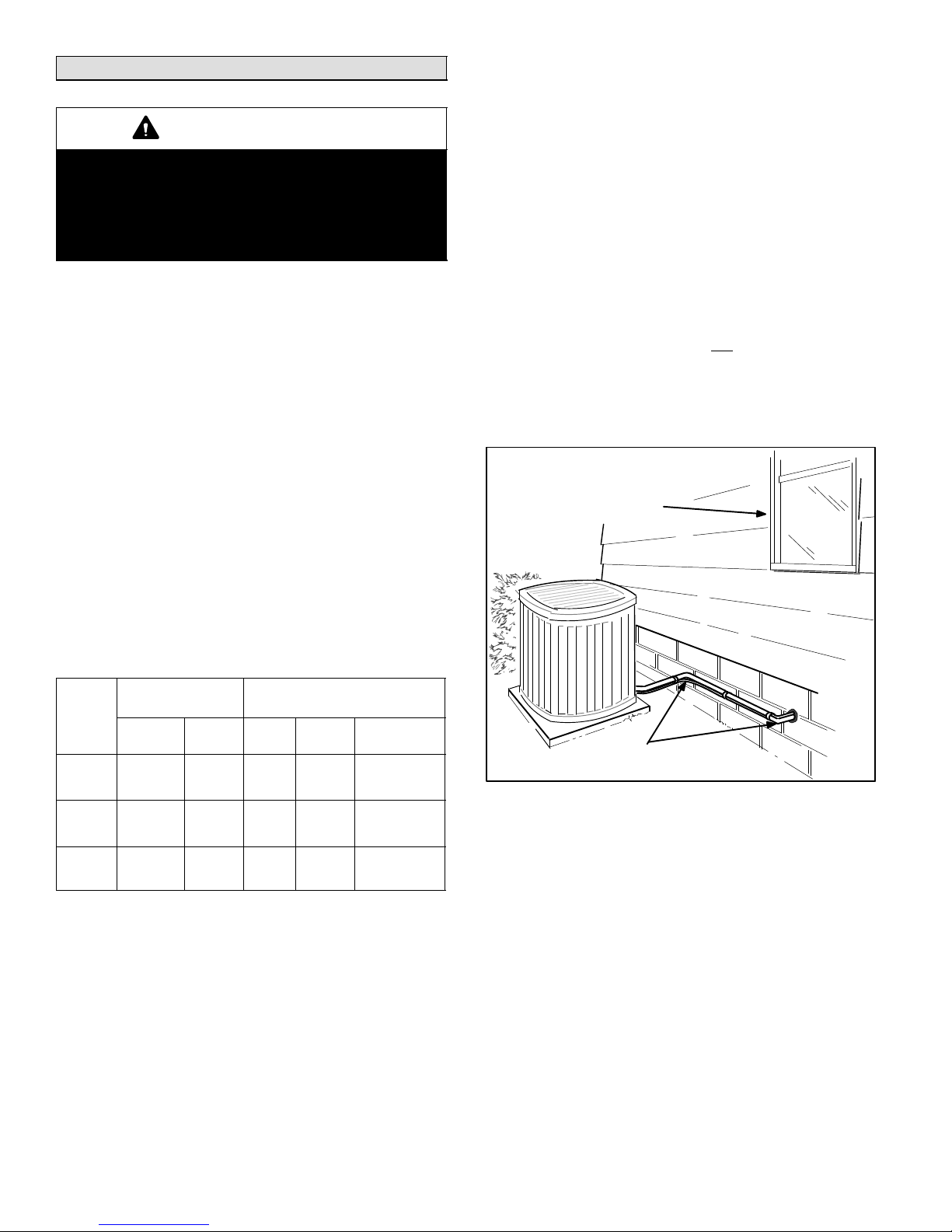
1. PlacementSome localities are adopting sound
ordinances based on the unit’s noise level observed
from the adjacent property, not from the installation
property. Install the unit as far as possible from the
property line. When possible, do not install the unit
directly outside a window. Glass has a very high level
of sound transmission. Figure 14 shows how to place
the outdoor unit and line set.
Install unit
away from
windows
Two 90° elbows installed in line set
will reduce line set vibration.
Figure 14. Outside Unit Placement
2. Line Set IsolationThe following illustrations
demonstrate procedures which ensure proper
refrigerant line set isolation.
Figure 15 on page 9 shows how to install line sets
on horizontal runs.
Figure 16 on page 9 shows how to install line sets
on vertical runs.
Figure 17 on page 9 shows how to make a
transition from horizontal to vertical
505244M 10/09
Page 8
 Loading...