

Lennox XP13-018, XP13-024, XP13-030, XP13-036, XP13-037 Service Literature
...
Page 1
©2005 Lennox Industries Inc.
Corp. 0528−L10
XP13
Service Literature
Revised 05−2008
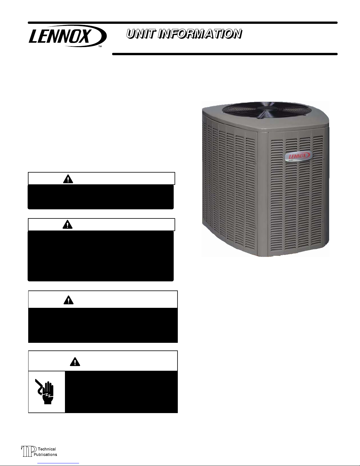
XP13 SERIES UNITS
The XP13 is a high efficiency residential split−system heat
pump unit, which features a scroll compressor and R−410A
refrigerant. XP13 units are available in sizes ranging from 1
1/2 through 5 tons. The series is designed for use with an
indoor unit with an expansion valve approved for R−410A.
This manual is divided into sections which discuss the major components, refrigerant system, charging procedure,
maintenance and operation sequence.
Information contained in this manual is intended for use by
qualified service technicians only. All specifications are
subject to change.
IMPORTANT
Operating pressures of this R−410A unit are higher
than pressures in R−22 units. Always use service
equipment rated for R−410A.
WARNING
Warranty will be voided if covered equipment is removed from original installation site. Warranty will
not cover damage or defect resulting from:
Flood, wind, lightning, or installation and operation in a corrosive atmosphere (chlorine, fluorine,
salt, recycled waste water, urine, fertilizers, or other damaging chemicals).
WARNING
Improper installation, adjustment, alteration, service
or maintenance can cause property damage, personal injury or loss of life. Installation and service must
be performed by a qualified installer or service
agency.
WARNING
Electric shock hazard. Can cause injury
or death. Before attempting to perform
any service or maintenance, turn the
electrical power to unit OFF at disconnect switch(es). Unit may have multiple
power supplies.
TABLE OF CONTENTS
Specifications / Electrical Page 2. . . . . . . . . . . . .
I Unit Information Page 3. . . . . . . . . . . . . . . . . . . .
II Unit Components Page 3. . . . . . . . . . . . . . . . . .
III Refrigerant System Page 8. . . . . . . . . . . . . . . .
IV Charging Page 10. . . . . . . . . . . . . . . . . . . . . . . . .
V Service and Recovery Page 13. . . . . . . . . . . . . .
VI Maintenance Page 14. . . . . . . . . . . . . . . . . . . . . .
VII Brazing Procedure Page 14. . . . . . . . . . . . . . . .
VIII Wiring Diagram Page 15. . . . . . . . . . . . . . . . . .

Page 2
SPECIFICATIONS
General
Model No. XP13−018 XP13−024 XP13−030 XP13−036 XP13−037 XP13−042 XP13−048 XP13−060
Data
Nominal Tonnage 1.5
2 2.5 3 3+ 3.5 4 5
Connections
Liquid line (o.d.) − in. 3/8 3/8 3/8 3/8 3/8 3/8 3/8 3/8
(sweat)
Vapor line (o.d.) 3/4
3/4 3/4 3/4 3/4 7/8 7/8 1−1/8
Refrigerant
1
R−410A charge furnished 8 lbs.
15 oz.
7 lbs.
7 oz.
7 lbs.
10 oz.
10 lbs.
2 oz.
10 lbs.
3 oz.
11 lbs.
10 oz.
11 lbs.
10 oz.
15 lbs.
0 oz.
Outdoor
Net face area
Outer coil 13.22 13.22 13.22 15.11 18.67 18.67 18.67 24.50
Coil sq. ft.
Inner coil 12.65
12.65 12.65 14.46 18.00 18.00 18.00 23.64
Tube diameter − in. 5/16 5/16 5/16 5/16 5/16 5/16 5/16 5/16
No. of Rows 2 2 2 2 2 2 2 2
Fins per inch 22 22 22 22 22 22 22 22
Outdoor
Diameter − in. 18 18 18 18 22 22 22 22
Fan
No. of blades 3
3 3 3 4 4 4 4
Motor hp 1/10 1/10 1/10 1/10 1/6 1/6 1/4 1/4
Cfm 2215 2215 2270 2330 3150 3150 3730 3980
Rpm 1040 1040 1050 1060 844 844 824 836
Watts 145 145 165 170 215 215 320 305
Shipping Data − lbs. 1 pkg. 189 188 192 208 235 260 267 305
ELECTRICAL DATA
Line voltage data − 60hz − 1 phase 208/230V 208/230V 208/230V 208/230V 208/230V 208/230V 208/230V 208/230V
3
Maximum overcurrent protection (amps) 20 30 30 35 35 40 50 60
2
Minimum circuit ampacity 11.9 17.5 18.4 21.6 21.9 23.2 28.9 34.6
Compressor
Rated load amps 8.97 13.46 14.1 16.67 16.67 17.69 21.79 26.28
p
Locked rotor amps 48 58 73 79 79 107 117 134
Power factor 0.98 0.98 0.98 0.99 0.99 0.99 0.99 0.99
Outdoor Fan
Full load amps 0.7 0.7 0.7 0.7 1.1 1.1 1.7 1.7
Motor
Locked Rotor Amps 1.4
1.4 1.4 1.4 2.1 2.1 2.1 3.1
OPTIONAL ACCESSORIES − must be ordered extra
Compressor Hard Start Kit
10J42
p
88M91
Compressor Crankcase Heater 93M04 Factory
Compressor Low Ambient
Cut−Off
45F08
Compressor Sound Cover 69J03
Freezestat
3/8 in. tubing 93G35
5/8 in. tubing 50A93
Low Ambient Kit 54M89
Low Pressure Switch Bypass
Thermostat
13W07
Mild Weather Kit 33M07
Monitor Kit − Service Light 76F53
Outdoor
Thermostat 56A87
Thermostat Kit
Mounting Box 31461
Refrigerant
Line Sets
L15−41−20
L15−41−30
L15−41−40
L15−41−50
L15−65−30
L15−65−40
L15−65−50
Field Fabricate
Time Delay Relay 58M81
NOTE − Extremes of operating range are plus 10% and minus 5% of line voltage.
1
Refrigerant charge sufficient for 15 ft. length of refrigerant lines.
2
Refer to National or Canadian Electrical Code manual to determine wire, fuse and disconnect size requirements.
3
HACR type breaker or fuse.
Page 3
I − UNIT INFORMATION
ELECTROSTATIC DISCHARGE (ESD)
Precautions and Procedures
CAUTION
Electrostatic discharge can affect electronic
components. Take precautions during unit installation and service to protect the unit’s electronic
controls. Precautions will help to avoid control
exposure to electrostatic discharge by putting
the unit, the control and the technician at the
same electrostatic potential. Neutralize electrostatic charge by touching hand and all tools on an
unpainted unit surface before performing any
service procedure.
All major components (indoor blower and coil) must be
matched according to Lennox recommendations for the
compressor to be covered under warranty. Refer to the Engineering Handbook for approved system matchups. A
misapplied system will cause erratic operation and can result in early compressor failure.
IMPORTANT
This unit must be matched with an indoor coil as
specified in Lennox’ Engineering Handbook.
II − UNIT COMPONENTS
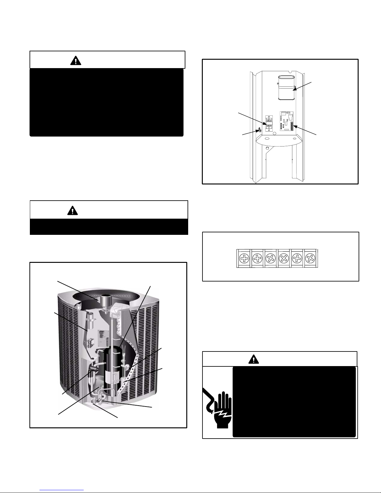
Unit components are illustrated in figure 1.
XP13 UNIT COMPONENTS
FIGURE 1
OUTDOOR FAN
COMPRESSOR
HIGH PRESSURE
SWITCH
REVERSING
VALV E
FILTER
DRIER
CONTROL
BOX
EXPANSION
VALV E
VAPOR LINE
SERVICE
VALV E
LIQUID LINE
SERVICE
VALV E
A − Control Box (Figure 2)
XP13 units are not equipped with a 24V transformer. All 24
VAC controls are powered by the indoor unit. Refer to wiring diagram.
FIGURE 2
DUAL CAPACITOR
(C12)
COMPRESSOR
CONTACTOR
(K1)
SINGLE PHASE UNIT CONTROL BOX
GROUNDING
LUG
DEFROST
CONTROL
(A108)
Electrical openings are provided under the control box cover. Field thermostat wiring is made to a 24V terminal strip
located on the defrost control board located in the control
box. See figure 3.
CRW1OY1 L
24V THERMOSTAT TERMINAL STRIP
FIGURE 3
1 − Compressor Contactor K1
The compressor is energized by a contactor located in the
control box. See figure 2. Single−pole contactors are used
in all XP13 series units. K1 is energized through the control board by the indoor thermostat terminal Y1 (24V) when
thermostat demand is present.
DANGER
Electric Shock Hazard.
May cause injury or death.
Line voltage is present at all components when unit is not in operation on
units with single pole contactors.
Disconnect all remote electrical power
supplies before opening unit panel.
Unit may have multiple power supplies.
Page 4
2 − Dual Capacitor C12
The compressor and fan in XP13 series units use permanent
split capacitor motors. The capacitor is located inside the unit
control box (see figure 2). A single dual" capacitor (C12) is
used for both the fan motor and the compressor (see unit wiring diagram). The fan side and the compressor side of the capacitor have different MFD ratings. See side of capacitor for
ratings.
3 − Defrost Control
The XP13 defrost system includes two components: a defrost thermostat and a defrost control.
Defrost Thermostat (Defrost Switch S6)
The defrost thermostat is located on the liquid line between
the check/expansion valve and the distributor. When defrost thermostat senses 42°F (5.5°C) or cooler, the thermostat contacts close and send a signal to the defrost control
board to start the defrost timing. It also terminates defrost
when the liquid line warms up to 70°F (21°C).
Defrost Control
The defrost control board includes the combined functions
of a time/temperature defrost control, defrost relay, diagnostic LEDs and terminal strip for field wiring connections.
The control provides automatic switching from normal heating operation to defrost mode and back. During compressor
cycle (call for defrost), the control accumulates compressor
run times at 30-, 60-, or 90-minute field−adjustable intervals. If the defrost thermostat is closed when the selected
compressor run time interval ends, the defrost relay is energized and defrost begins.
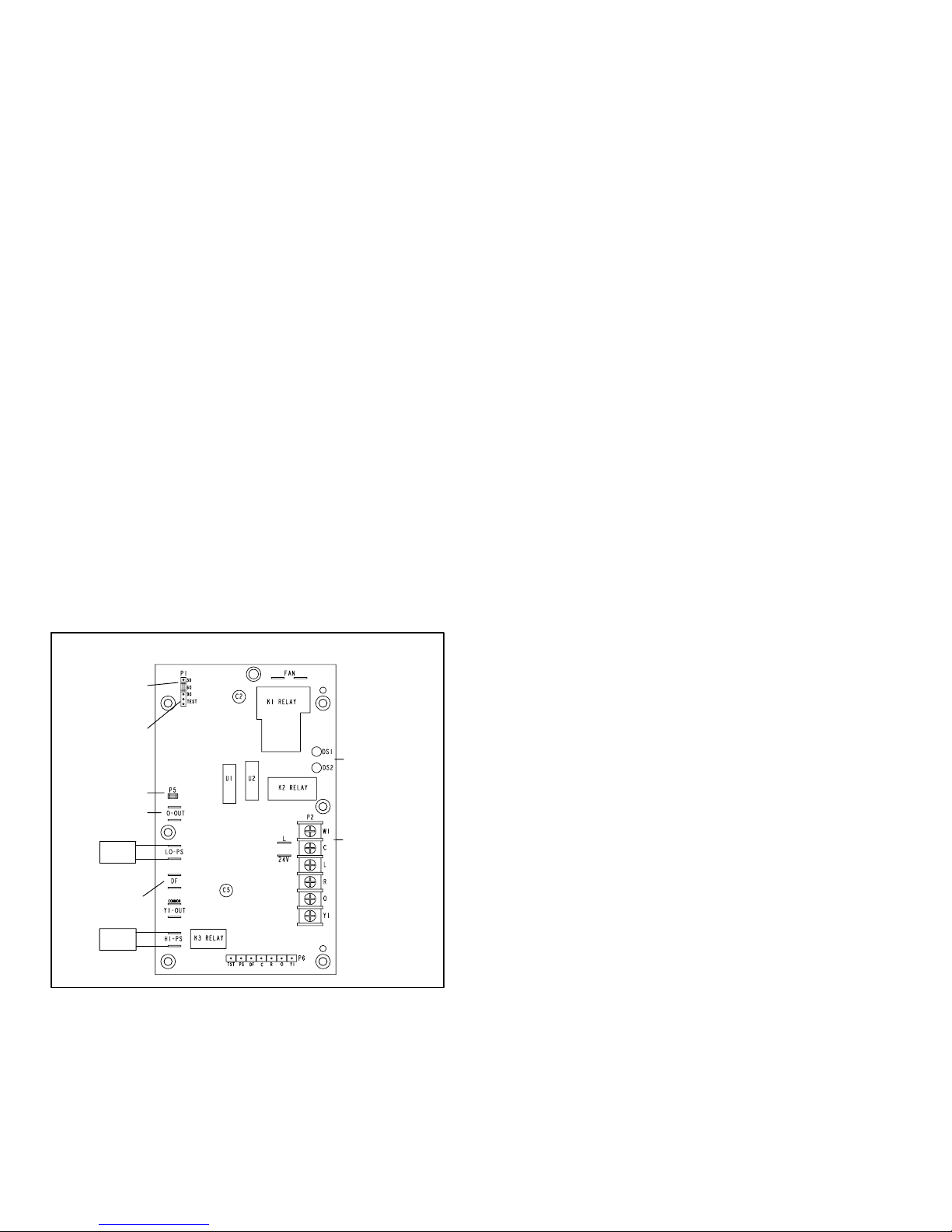
XP13 Outdoor Unit Defrost Control Board
24V TERMINAL
STRIP
CONNECTIONS
DIAGNOSTIC
LEDS
HIGH PRESSURE
SWITCH
TEST
PINS
FIELD SELECT
TIMING PINS
REVERSING
VALV E
DEFROST
THERMOSTAT
LOW PRESSURE
SWITCH
COMPRESSOR
DELAY PINS
S4
S87
FIGURE 4
Defrost Control Timing Pins
Each timing pin selection provides a different accumulated compressor run time period for one defrost cycle.
This time period must occur before a defrost cycle is initiated. The defrost interval can be adjusted to 30, 60 or 90
minutes (see figure 4). The defrost timing jumper is facto-
ry−installed to provide a 60−minute defrost interval. If the
timing selector jumper is not in place, the control defaults
to a 90−minute defrost interval. The maximum defrost period is 14 minutes and cannot be adjusted.
A TEST option is provided for troubleshooting. The TEST
mode may be started any time the unit is in the heating
mode and the defrost thermostat is closed or jumpered. If the jumper is in the TEST position at power-up, the
control will ignore the test pins. When the jumper is placed
across the TEST pins for two seconds, the control will enter
the defrost mode. If the jumper is removed before an additional 5−second period has elapsed (7 seconds total), the
unit will remain in defrost mode until the defrost thermostat
opens or 14 minutes have passed. If the jumper is not removed until after the additional 5−second period has
elapsed, the defrost will terminate and the test option will
not function again until the jumper is removed and re−applied.
Compressor Delay
The defrost board has a field−selectable function to reduce
occasional sounds that may occur while the unit is cycling in
and out of the defrost mode. The compressor will be cycled
off for 30 seconds going in and out of the defrost mode
when the compressor delay jumper is removed.
NOTE − The 30-second compressor feature is ignored
when the defrost test pins are jumpered.
Time Delay
The timed-off delay is five minutes long. The delay helps to
protect the compressor from short-cycling in case the power to the unit is interrupted or a pressure switch opens. The
delay is bypassed by placing the timer select jumper across
the TEST pins for 0.5 seconds.
Pressure Switch Circuit
The defrost control incorporates two pressure switch circuits. The high pressure switch (S4) is factory-connected to
the board’s HI PS terminals (see figure 4). The board also
includes a low pressure, or loss-of-charge-pressure, switch
(S87). Switches are shown in the unit wiring diagram. During a single demand cycle, the defrost control will lock out
the unit after the fifth time that the circuit is interrupted by
any pressure switch wired to the control board. In addition,
the diagnostic LEDs will indicate a locked-out pressure
switch after the fifth occurrence of an open pressure switch
(see Table 1). The unit will remain locked out until power to
the board is interrupted, then re-established or until the
jumper is applied to the TEST pins for 0.5 seconds.
Some XP13 units will be equipped with an optional by−pass
switch wired in parallel with the low pressure switch (S87).
This by−pass switch prevents nuisance trips when ambient
conditions drop below 15° F.
NOTE − The defrost control board ignores input from the
low-pressure switch terminals as follows:
during the TEST mode,
during the defrost cycle,
during the 90-second start-up period,
and for the first 90 seconds each time the reversing valve
switches heat/cool modes.
Diagnostic LEDs
The defrost board uses two LEDs for diagnostics. The LEDs
flash a specific sequence according to the condition.
Page 5
TABLE 1
Defrost Control Board Diagnostic LED
Mode Green LED (DS2) Red LED (DS1)
No power to control
OFF OFF
Normal operation /
power to control
Simultaneous Slow FLASH
Anti-short cycle
lockout
Alternating Slow FLASH
Low pressure
switch fault
OFF Slow FLASH
Low pressure
switch lockout
OFF ON
High pressure
switch fault
Slow FLASH OFF
High pressure
switch lockout
ON OFF
B − Compressor
The scroll compressors in all XP13 model units are designed for use with R−410A refrigerant and operation at
high pressures. Compressors are shipped from the factory
with 3MA (32MMMA) P.O.E. oil. See electrical section in
this manual for compressor specifications.
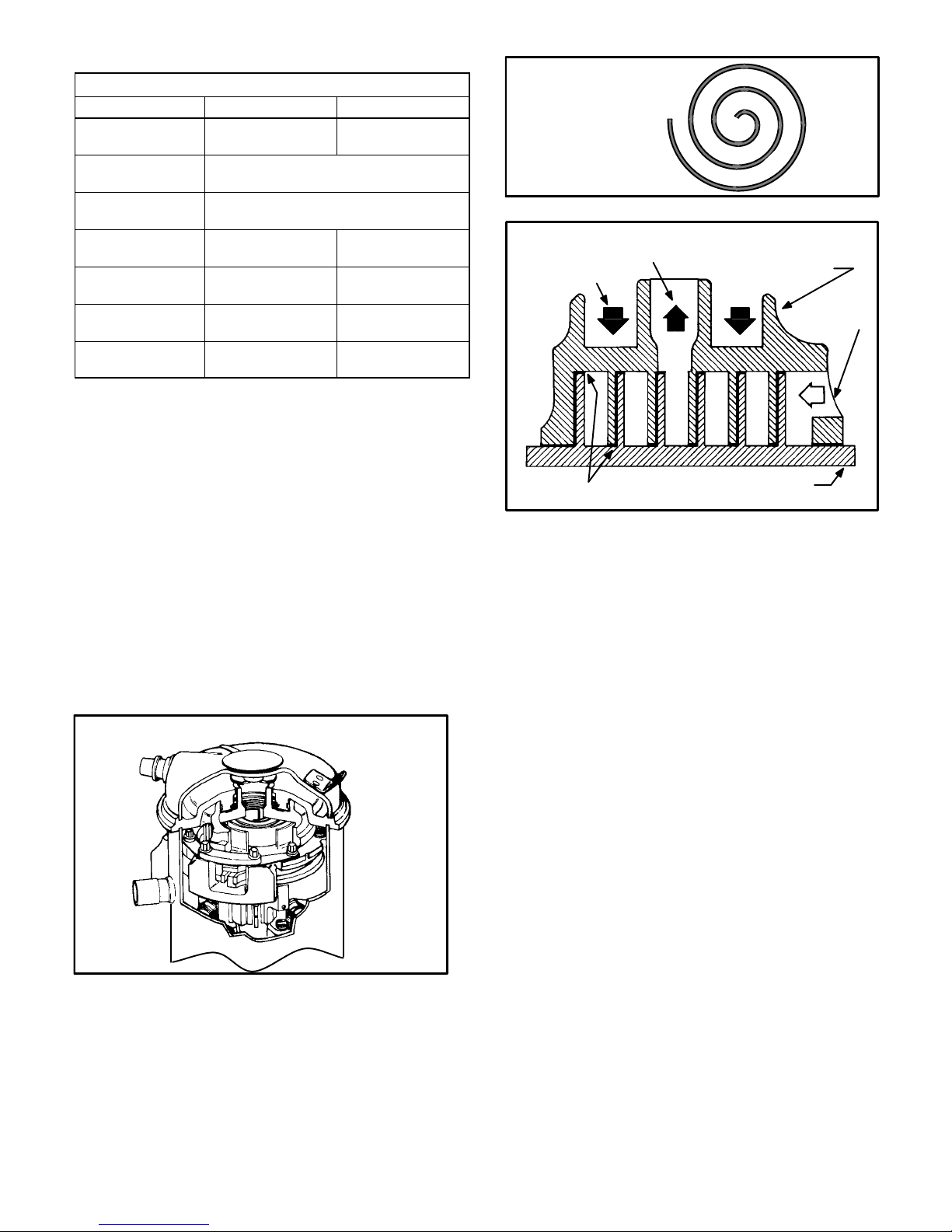
The scroll compressor design is simple, efficient and requires
few moving parts. A cutaway diagram of the scroll compressor
is shown in figure 5. The scrolls are located in the top of the
compressor can and the motor is located just below. The oil
level is immediately below the motor.
The scroll is a simple compression concept centered around
the unique spiral shape of the scroll and its inherent properties.
Figure 6 shows the basic scroll form. Two identical scrolls are
mated together forming concentric spiral shapes (figure 7).
One scroll remains stationary, while the other is allowed to "orbit" (figure 8). Note that the orbiting scroll does not rotate or turn
but merely orbits the stationary scroll.
FIGURE 5
SCROLL COMPRESSOR
DISCHARGE
SUCTION
NOTE − During operation, the head of a scroll compressor may
be hot since it is in constant contact with discharge gas.
FIGURE 6
SCROLL FORM
FIGURE 7
STATIONARY SCROLL
ORBITING SCROLL
DISCHARGE
SUCTION
CROSS−SECTION OF SCROLLS
TIPS SEALED BY
DISCHARGE PRESSURE
DISCHARGE
PRESSURE
The counterclockwise orbiting scroll draws gas into the outer
crescent shaped gas pocket created by the two scrolls (figure 8
− 1). The centrifugal action of the orbiting scroll seals off the
flanks of the scrolls (figure 8 − 2). As the orbiting motion continues, the gas is forced toward the center of the scroll and the
gas pocket becomes compressed (figure 8 − 3). When the
compressed gas reaches the center, it is discharged vertically
into a chamber and discharge port in the top of the compressor
(figure 7). The discharge pressure forcing down on the top
scroll helps seal off the upper and lower edges (tips) of the
scrolls (figure 7). During a single orbit, several pockets of gas
are compressed simultaneously providing smooth continuous
compression.
The scroll compressor is tolerant to the effects of liquid return. If
liquid enters the scrolls, the orbiting scroll is allowed to separate
from the stationary scroll. The liquid is worked toward the center of the scroll and is discharged. If the compressor is replaced, conventional Lennox cleanup practices must be used.
Due to its efficiency, the scroll compressor is capable of drawing a much deeper vacuum than reciprocating compr essors. Deep vacuum operation can cause internal fusite
arcing resulting in damaged internal parts and will result
in compressor failure. Never use a scroll compressor for
evacuating or pumping−down" the system. This type of
damage can be detected and will result in denial of warranty claims.
The scroll compressor is quieter than a reciprocating compressor, however, the two compressors have much different sound characteristics. The sounds made by a scroll
compressor do not affect system reliability, performance,
or indicate damage.
 Loading...