

Lennox XC21 Series Unit Information
Page 1
2010 Lennox Industries Inc.
Revised October 12, 2010
XC21
Service Literature
Corp. 1007−L2
XC21 (HFC−410A) SERIES UNITS
(non−icomfortt and icomfortt ENABLED)
THIS SERVICE MANUAL IS APPLICABLE TO BUILD
XC21−XXX−230−04 OR LATER.
NOTICE
A thermostat is not included and must be ordered
separately.
D The Lennox icomfort Touch thermostat must be used
in communicating applications.
D In non−communicating applications, the Lennox
ComfortSense
®
7000 thermostat may be used, as well
as other non−communicating thermostats.
In all cases, setup is critical to ensure proper system
operation.
Field wiring examples for non−communicating
applications begin on page 24.
See the icomfort Toucht thermostat Quick Start Guide
for communicating and partial communicating field wiring
connections.
WARNING
Improper installation, adjustment, alteration, service or
maintenance can cause personal injury, loss of life, or
damage to property.
Installation and service must be performed by a licensed
professional installer (or equivalent) or a service agency.
Accessories
For update−to−date information, see any of the following
publications:
S Lennox XC21 Engineering Handbook
S Lennox Product Catalog
S Lennox Price Book
TABLE OF CONTENTS
Model Number Identification 2. . . . . . . . . . . . . . . . . . . .
Typical Serial Number Identification 2. . . . . . . . . . . . . .
Specifications 2. . . . . . . . . . . . . . . . . . . . . . . . . . . . . . . . .
Electrical Data 3. . . . . . . . . . . . . . . . . . . . . . . . . . . . . . . .
Unit Dimensions 4. . . . . . . . . . . . . . . . . . . . . . . . . . . . . .
Unit Parts Arrangement 5. . . . . . . . . . . . . . . . . . . . . . . .
Operating Gauge Set and Service Valves 6. . . . . . . . .
Unit Placement 8. . . . . . . . . . . . . . . . . . . . . . . . . . . . . . .
Removing and Installing Panels 11. . . . . . . . . . . . . . . . .
New or Replacement Line Set 12. . . . . . . . . . . . . . . . . .
Brazing Connections 14. . . . . . . . . . . . . . . . . . . . . . . . . . .
Flushing the System 17. . . . . . . . . . . . . . . . . . . . . . . . . . .
Leak Testing the System 19. . . . . . . . . . . . . . . . . . . . . . .
Evacuating the System 21. . . . . . . . . . . . . . . . . . . . . . . . .
Electrical 22. . . . . . . . . . . . . . . . . . . . . . . . . . . . . . . . . . . . .
Field Control Wiring 24. . . . . . . . . . . . . . . . . . . . . . . . . . .
Air Conditioner Control (A175) Jumpers
and Terminals 26. . . . . . . . . . . . . . . . . . . . . . . . . . . . . . . . .
Unit Start−Up 27. . . . . . . . . . . . . . . . . . . . . . . . . . . . . . . . . .
System Refrigerant 27. . . . . . . . . . . . . . . . . . . . . . . . . . .
Operating and Temperature Pressures 31. . . . . . . . . .
System Operations 32. . . . . . . . . . . . . . . . . . . . . . . . . . . .
System Status, Fault and Lockout LED Codes 36. . . .
Component Field Configuration and
Troubleshooting 41. . . . . . . . . . . . . . . . . . . . . . . . . . . . . . .
Maintenance 49. . . . . . . . . . . . . . . . . . . . . . . . . . . . . . . . . .
SunSource
®
Home Energy System 50. . . . . . . . . . . . . .
Checklists 50. . . . . . . . . . . . . . . . . . . . . . . . . . . . . . . . . . . .
Unit Wiring Diagrams 52. . . . . . . . . . . . . . . . . . . . . . . . . .
Unit Sequence of Operations 54. . . . . . . . . . . . . . . . . . .
The XC21 is a high efficiency residential split−system air
conditioner unit, which features a one−stage scroll
compressor, icomfortt control and HFC−410A refrigerant.
Units are available in 2, 3, 4 and 5−ton sizes. This model
series is designed for use with an expansion valve
metering device only. Refer to the XC17 Engineering
Handbook for ordering the correct indoor coil expansion
valve.
This model is also SunSourcet ready beginning with
XC21−XXX−230−05 build.
This document provides information only on build
XC21−XXX−230−04 and later which features the new air
conditioner control hardware and other enhancements.
Refer to Corp. 0504−L2 for earlier model version service
related information.
Page 2
XC21
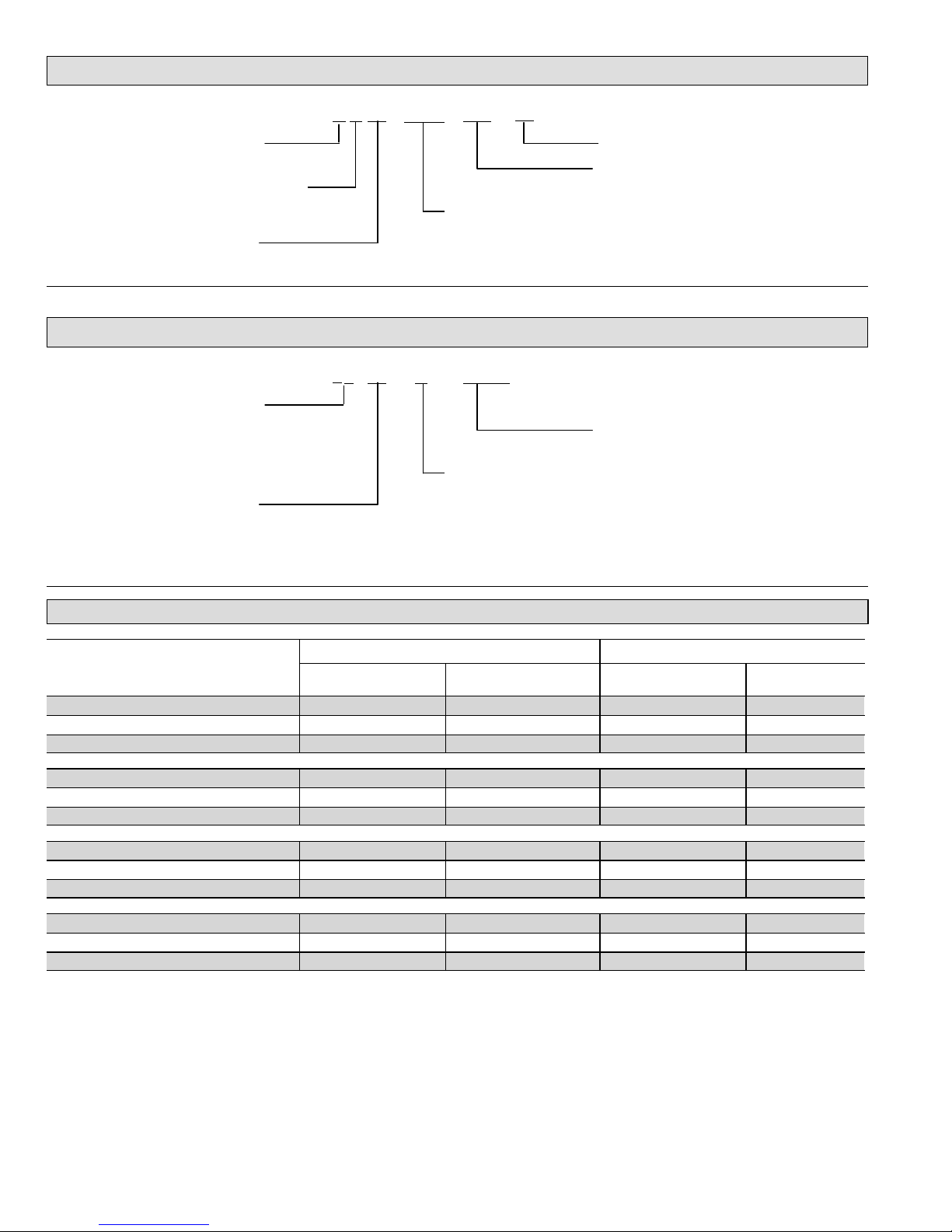
Model Number Identification
C 21
XXX
Unit Type
C = Air Conditioner
Series
Nominal Cooling Capacity
024 = 2 tons
036 = 3 tons
048 = 4 tons
060 = 5 tons
Minor Revision Number
230
Voltage
230 = 208/230V−1ph−60hz
Refrigerant Type
X = R−410A
X
04
Typical Serial Number Identification
8 09 C
Year Code
08 = 2008
09 = 2009
10 = 2010
Month Code
A = January
B = February
C = March
05716
5 (or 6) Digit Unique
Number
Location Code
19 = Saltillo, Mexico
20 = Gainesville, FL
56 = Stuttgart, AR
58 = Marshalltown, IA
5
Specifications
Model Number
Unit Outdoor Fan
Sound Rating Number
(dB)
1
Factory Refrigerant
Charge
2
Number of Blades Diameter − inches.
XC21−024−230−04 69 12 lbs. 0 oz. 3 26.0
XC21−024−230−05 69 11 lbs. 12 oz. 5 26.1
XC21−024−230−06 69 11 lbs. 12 oz. 5 26.1
XC21−036−230−04 71 12 lbs. 5 oz. 3 26.0
XC21−036−230−05 71 12 lbs. 5 oz. 5 26.1
XC21−036−230−06 71 12 lbs. 5 oz. 5 26.1
XC21−048−230−04 73 13 lbs. 0 oz. 3 26.1
XC21−048−230−05 73 13 lbs. 0 oz. 5 26.1
XC21−048−230−06 73 13 lbs. 0 oz. 5 26.1
XC21−060−230−04 73 13 lbs. 0 oz. 3 26.0
XC21−060−230−05 73 13 lbs. 0 oz. 5 26.1
XC21−060−230−06 73 13 lbs. 0 oz. 5 26.1
1
Tested according to AHRI Standard 270−2008 test conditions.
2
Refrigerant charge sufficient for 15 feet length of refrigerant lines.
Page 3
XC21
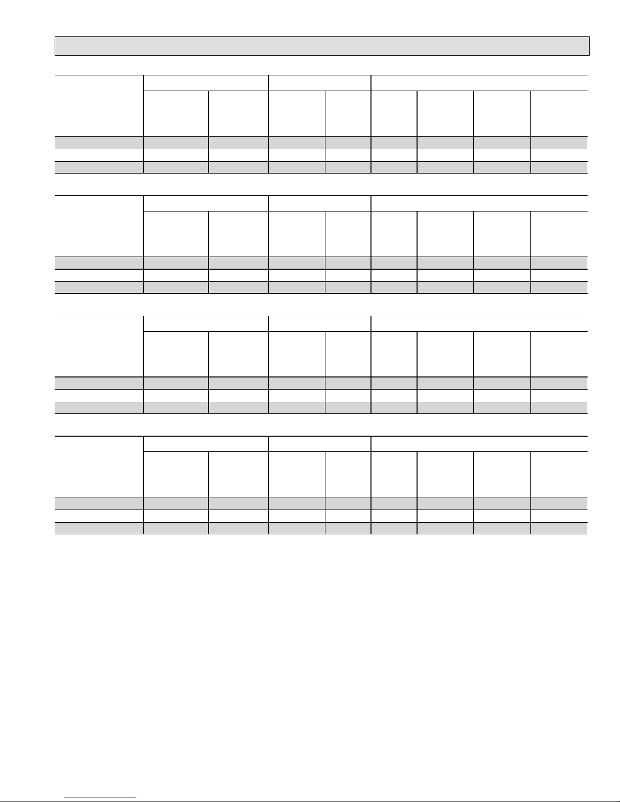
Electrical Data
208/230V−60 Hz−1 Ph
Model Number
Unit Compressor Condenser Fan
Maximum
Over−
current
Protection
(amps)
1
Minimum
Circuity
Ampacity
2
Rated Load
Amps (RLA)
Locked
Rotor
Amps
(LRA)
Motor HP
Nominal
RPM 1−Stage
Nominal
RPM 2−Stage
Full Load
Amps (FLA)
XC21−024−230−04 25 15.7 10.3 52.0 1/3 700 820 2.8
XC21−024−230−05 30 18.9 13.5 58.3 1/4 475 550 2.0
XC21−024−230−06 30 18.9 13.5 58.3 1/4 475 550 2.0
208/230V−60 Hz−1 Ph
Model Number
Unit Compressor Condenser Fan
Maximum
Over−
current
Protection
(amps)
1
Minimum
Circuity
Ampacity
2
Rated Load
Amps (RLA)
Locked
Rotor
Amps
(LRA)
Motor HP
Nominal
RPM 1−Stage
Nominal
RPM 2−Stage
Full Load
Amps (FLA)
XC21−036−230−04 40 23.7 16.7 82.0 1/3 700 820 2.8
XC21−036−230−05 35 22.9 16.7 82.0 1/4 475 550 2.0
XC21−036−230−06 35 22.9 16.7 82.0 1/4 475 550 2.0
208/230V−60 Hz−1 Ph
Model Number
Unit Compressor Condenser Fan
Maximum
Over−
current
Protection
(amps)
1
Minimum
Circuity
Ampacity
2
Rated Load
Amps (RLA)
Locked
Rotor
Amps
(LRA)
Motor HP
Nominal
RPM 1−Stage
Nominal
RPM 2−Stage
Full Load
Amps (FLA)
XC21−048−230−04 50 29.3 21.2 96.0 1/3 700 820 2.8
XC21−048−230−05 45 28.5 21.2 96.0 1/4 600 675 2.0
XC21−048−230−06 45 28.5 21.2 96.0 1/4 600 675 2.0
208/230V−60 Hz−1 Ph
Model Number
Unit Compressor Condenser Fan
Maximum
Over−
current
Protection
(amps)
1
Minimum
Circuity
Ampacity
2
Rated Load
Amps (RLA)
Locked
Rotor
Amps
(LRA)
Motor HP
Nominal
RPM 1−Stage
Nominal
RPM 2−Stage
Full Load
Amps (FLA)
XC21−060−230−04 60 34.9 25.7 118.0 1/3 700 820 2.8
XC21−060−230−05 50 25.7 25.7 118.0 1/4 600 675 2.0
XC21−060−230−06 50 25.7 25.7 118.0 1/4 600 675 2.0
1
HACR type circuit breaker or fuse.
2
Refer to National or Canadian Electrical Code manual to determine wire, fuse and disconnect size requirements.
Page 4
XC21
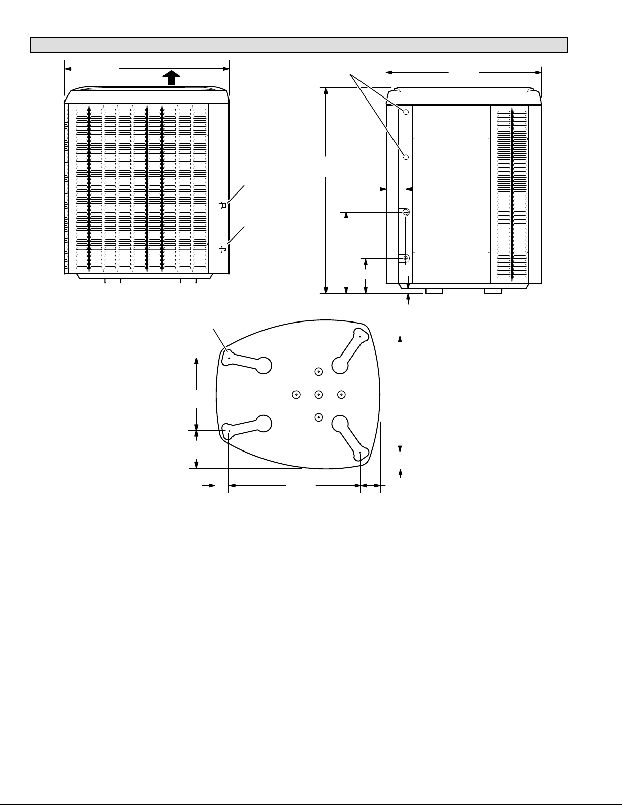
Unit Dimensions − Inches (mm) and Parts Arrangement
39−1/2
(1003)
35−1/2
(902)
47
(1194)
18−1/2
(470)
8 (203)
1 (25)
4−1/2
(114)
LIQUID
LINE
INLET
ELECTRICAL
INLETS
SIDE VIEW
ACCESS VIEW
DISCHARGE
AIR
4−5/8
(117)
BASE WITH ELONGATED LEGS
16−7/8
(429)
8−3/4
(222)
26−7/8
(683)
3−3/4 (95)
30−3/4
(781)
3−1/8
(79)
SUCTION
LINE
INLET
UNIT SUPPORT
FEET
Page 5
XC21
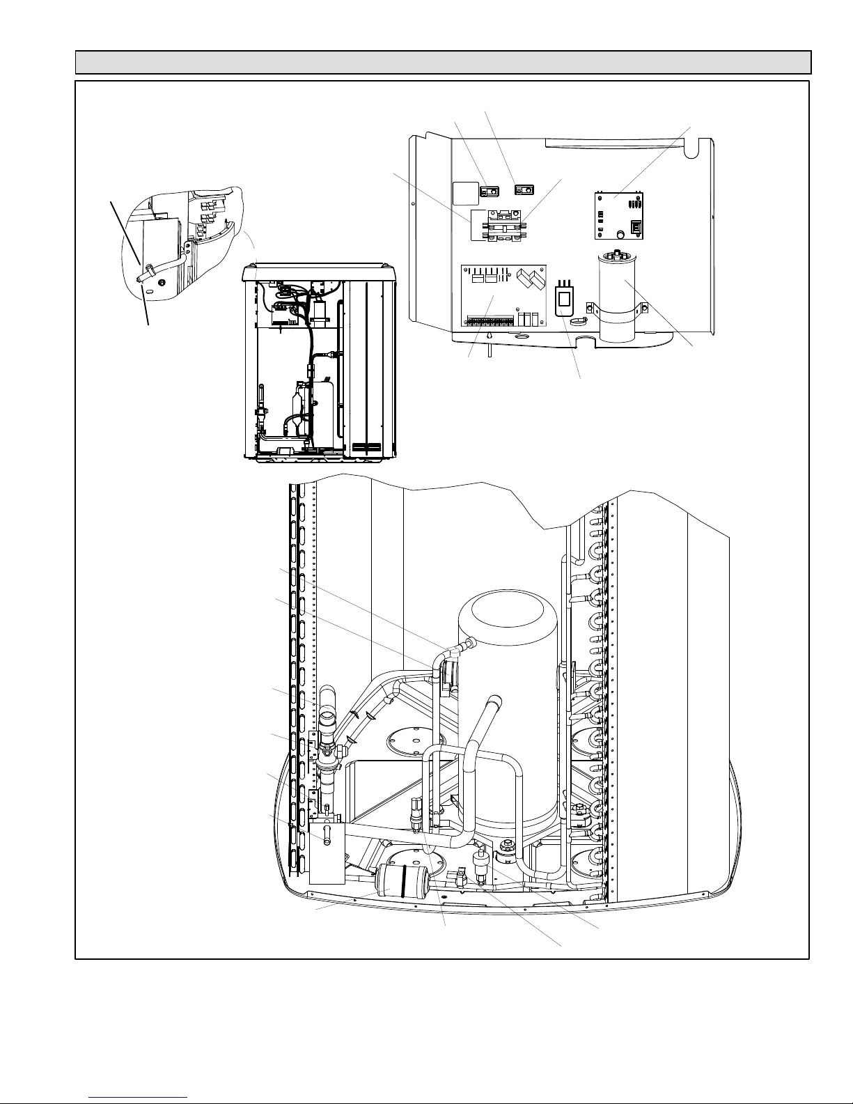
Typical Unit Parts Arrangement
LIQUID LINE FILTER
DRIER (SINGLE FLOW)
LIQUID LINE SER-
VICE VALVE PORT
SUCTION LINE SERVICE
VALVE PORT
FIELD CONNECTION FOR
SUCTION LINE
HIGH DISCHARGE LINE
TEMPERATURE SENSOR (RT28)
LOW PRESSURE SWITCH
(S87)
HIGH PRESSURE SWITCH (S4)
CRANKCASE THERMOSTAT (S40)
COMPRESSOR HARNESS
FIELD CONNECTION FOR
LIQUID LINE
GROUND LUG
HIGH VOLTAGE FIELD
CONNECTIONS
CONTACTOR−1
POLE (K1)
MAIN CONTROL
(A175)
CAPACITOR (C12)
FAN MOTOR CONTROL (A177)
(BUILD −05 AND LATER)
WIRE TIE
OUTDOOR AMBIENT
TEMPERATURE
SENSOR (RT13)
FAN MOTOR SURGE PROTECTION (BUILD
−05 ONLY) LATER VERSIONS HAVE SURGE
PROTECTION BUILT INTO FAN MOTOR.
SECOND GROUND LUG FOR SOURCESOURCE
®
(BUILD −05 AND LATER)
Figure 1. Plumbing, Switches and Sensor Components
Page 6
XC21
WARNING
This product and/or the indoor unit it is matched with may
contain fiberglass wool.
Disturbing the insulation during installation,
maintenance, or repair will expose you to fiberglass wool
dust. Breathing this may cause lung cancer. (Fiberglass
wool is known to the State of California to cause cancer.)
Fiberglass wool may also cause respiratory, skin, and
eye irritation.
To reduce exposure to this substance or for further
information, consult material safety data sheets available
from address shown below, or contact your supervisor.
Lennox Industries Inc.
P.O. Box 799900
Dallas, TX 75379−9900
IMPORTANT
This unit must be matched with an indoor coil as
specified in Lennox’ Engineering Handbook. Coils
previously charged with HCFC−22 must be flushed.
CAUTION
Physical contact with metal edges and corners while
applying excessive force or rapid motion can result in
personal injury. Be aware of, and use caution when
working nearby these areas during installation or while
servicing this equipment.
IMPORTANT
The Clean Air Act of 1990 bans the intentional venting of
refrigerant (CFCs, HCFCs AND HFCs) as of July 1, 1992.
Approved methods of recovery, recycling or reclaiming
must be followed. Fines and/or incarceration may be
levied for noncompliance.
WARNING
Electric Shock Hazard. Can cause injury
or death. Unit must be grounded in
accordance with national and local
codes.
Line voltage is present at all components
when unit is not in operation on units with
single-pole contactors. Disconnect all
remote electric power supplies before
opening access panel. Unit may have
multiple power supplies.
Operating Gauge Set and Service Valves
These instructions are intended as a general guide and do
not supersede local codes in any way. Consult authorities
who have jurisdiction before installation.
TORQUE REQUIREMENTS
When servicing or repairing heating, ventilating, and air
conditioning components, ensure the fasteners are
appropriately tightened. Table 1 shows torque values for
fasteners.
IMPORTANT
Only use Allen wrenches of sufficient hardness (50Rc −
Rockwell Harness Scale minimum). Fully insert the
wrench into the valve stem recess.
Service valve stems are factory−torqued (from 9 ft−lbs for
small valves, to 25 ft−lbs for large valves) to prevent
refrigerant loss during shipping and handling. Using an
Allen wrench rated at less than 50Rc risks rounding or
breaking off the wrench, or stripping the valve stem
recess.
See the Lennox Service and Application Notes #C−08−1
for further details and information.
IMPORTANT
To prevent stripping of the various caps used, the
appropriately sized wrench should be used and fitted
snugly over the cap before tightening.
Table 1. Torque Requirements
Parts Recommended Torque
Service valve cap 8 ft.− lb. 11 NM
Sheet metal screws 16 in.− lb. 2 NM
Machine screws #10 28 in.− lb. 3 NM
Compressor bolts 90 in.− lb. 10 NM
Gauge port seal cap 8 ft.− lb. 11 NM
USING MANIFOLD GAUGE SET
When checking the system charge, only use a manifold
gauge set that features low loss anti−blow back fittings.
Manifold gauge set used with HFC−410A refrigerant
systems must be capable of handling the higher system
operating pressures. The gauges should be rated for use
with pressures of 0 − 800 psig on the high side and a low
side of 30" vacuum to 250 psig with dampened speed to
500 psi. Gauge hoses must be rated for use at up to 800
psig of pressure with a 4000 psig burst rating.
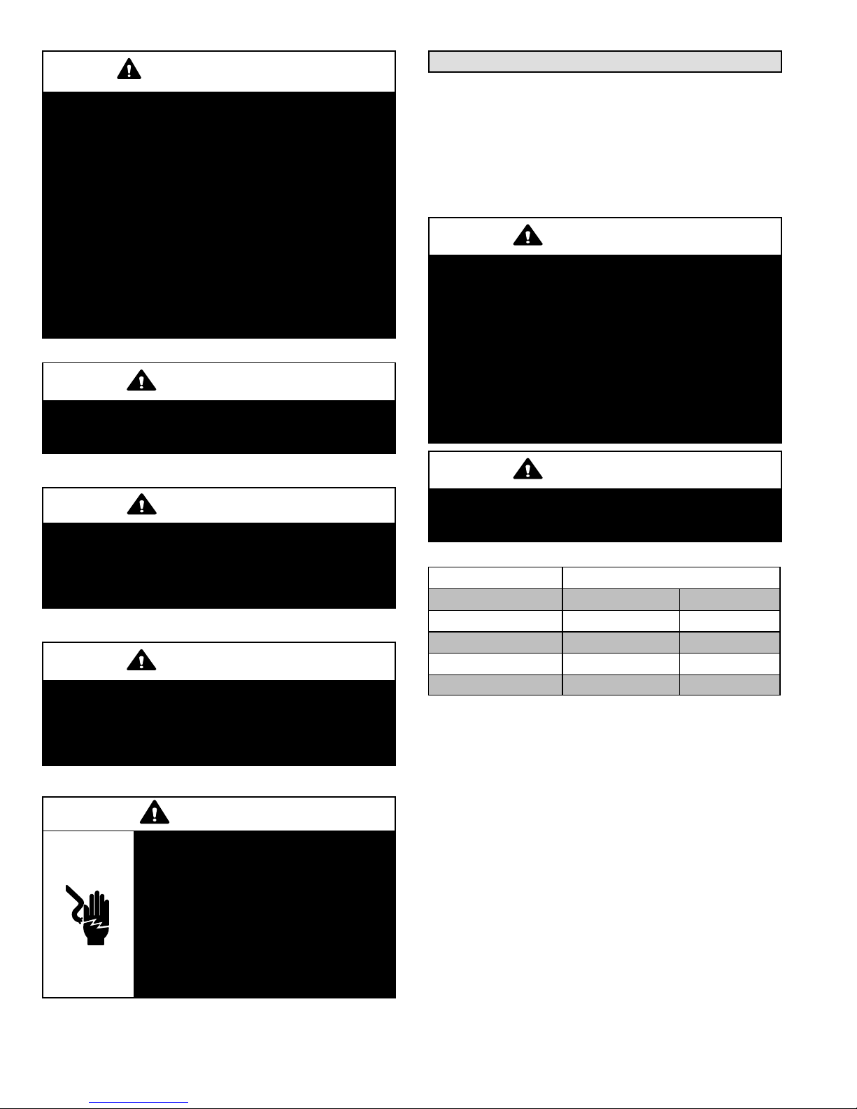
OPERATING SERVICE VALVES
The liquid and vapor line service valves are used for
removing refrigerant, flushing, leak testing, evacuating,
checking charge and charging.
Each valve is equipped with a service port which has a
factory−installed valve stem.
Figure 2 provides information
on how to access and operating both angle and ball service
valves.
Page 7
XC21
(VALVE STEM SHOWN
CLOSED) INSERT HEX
WRENCH HERE
SERVICE PORT CORE
SERVICE PORT CAP
ANGLE−TYPE SERVICE VALVE
(FRONT−SEATED CLOSED)
TO OUTDOOR UNIT
STEM CAP
(VALVE STEM SHOWN OPEN)
INSERT HEX WRENCH HERE
TO INDOOR
UNIT
ANGLE−TYPE SERVICE VALVE
(BACK−SEATED OPENED)
BALL (SHOWN
CLOSED)
SERVICE PORT
CORE
TO INDOOR UNIT
TO OUTDOOR
UNIT
TO OPEN ROTATE STEM
COUNTERCLOCKWISE 90°.
TO CLOSE ROTATE STEM
CLOCKWISE 90°.
SERVICE PORT
SERVICE PORT
CAP
STEM CAP
VALV E
STEM
SERVICE VALVES
ANGLE AND BALL
Operating Angle Type Service Valve:
1. Remove stem cap with an appropriately sized wrench.
2. Use a service wrench with a hex−head extension (3/16" for liquid line valve sizes and 5/16" for vapor line valve sizes) to back
the stem out counterclockwise as far as it will go.
Operating Ball Type Service Valve:
1. Remove stem cap with an appropriately sized wrench.
2. Use an appropriately sized wrenched to open. To open valve,
rotate stem counterclockwise 90°. To close, rotate stem
clockwise 90°.
1
2
3
4
5
6
7
8
9
10
11
12
1/12 TURN
To Access Service Port:
A service port cap protects the service port core from contamination and
serves as the primary leak seal.
1. Remove service port cap with an appropriately sized wrench.
2. Connect gauge set to service port.
3. When testing is completed, replace service port cap and tighten as
follows:
S With torque wrench: Finger tighten and
torque cap per table 1.
S Without torque wrench: Finger tighten and
use an appropriately sized wrench to turn
an additional 1/6 turn clockwise.
1
2
3
4
5
6
7
8
9
10
11
12
1/6 TURN
WHEN SERVICE VALV E IS CLOSED, THE SERVICE PORT IS
OPEN
TO THE LINE SET AND INDOOR UNIT.
When service valve is OPEN, the service port is
open to linE set, indoor and outdoor unit.
Reinstall Stem Cap:
Stem cap protects the valve stem from damage and serves as the
primary seal. Replace the stem cap and tighten as follows:
S With Torque Wrench: Finger tighten and then
torque cap per table 1.
S Without Torque Wrench: Finger tighten and
use an appropriately sized wrench to turn an
additional 1/12 turn clockwise.
NOTE A label with specific torque requirements may be affixed to the stem cap. If the label is present, use the specified torque.
Figure 2. Angle and Ball Service Valves
Page 8
XC21
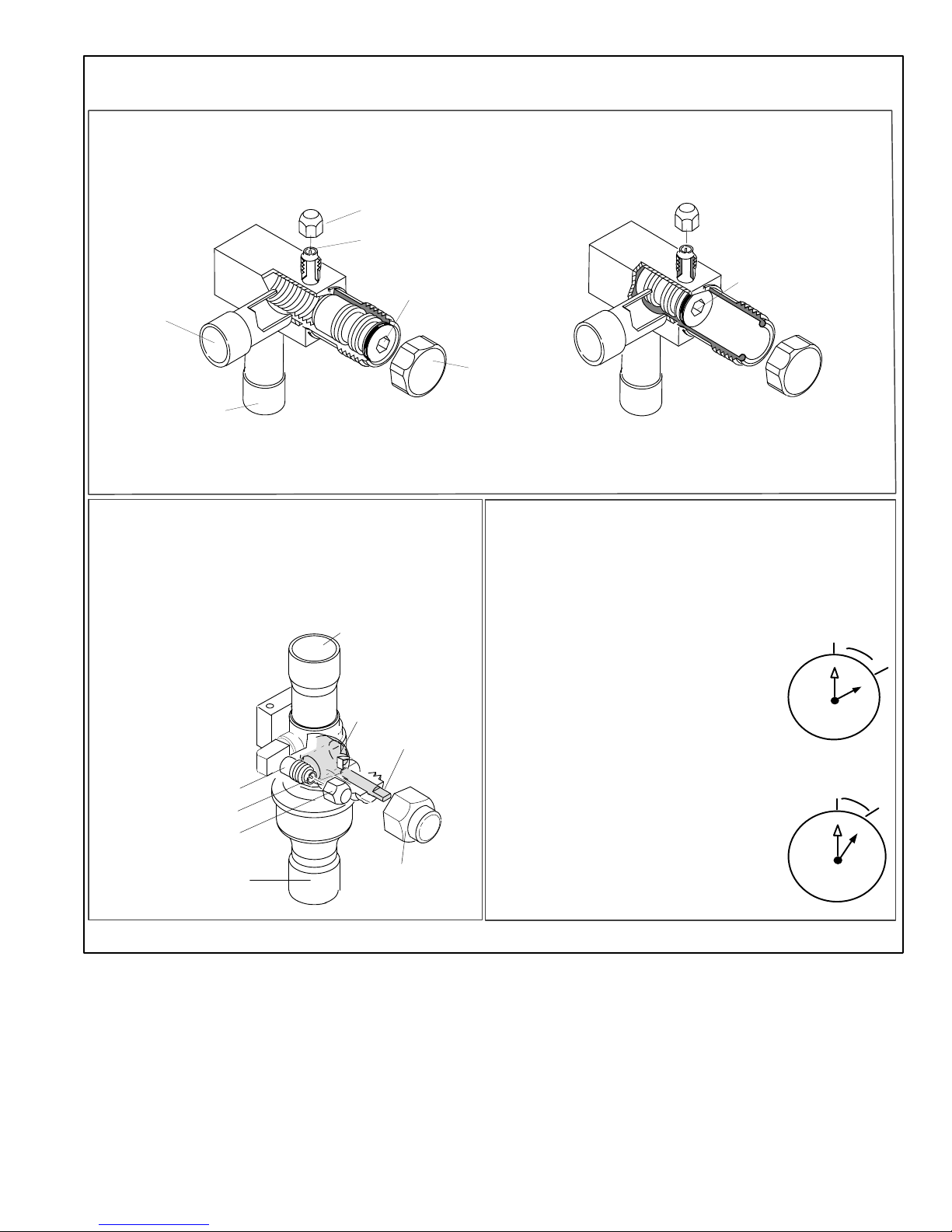
CONTROL PANEL
ACCESS
LOCATION
6 (152)
36 (914)
12 (305)
30 (762)
LINE SET
CONNECTIONS
24 (610)
LINE SET
CONNECTIONS
ACCESS PANEL
REAR VIEW OF UNIT
48 (1219)
MINIMUM CLEARANCE BETWEEN
TWO UNITS
CLEARANCE ON ALL SIDES INCHES (MILLIMETERS)
ACCESS PANEL
MINIMUM CLEARANCE
ABOVE UNIT
NOTES:
S Clearance to one of the other three
sides must be 36 inches (914mm).
S Clearance to one of the remaining
two sides may be 12 inches
(305mm) and the final side may be
6 inches (152mm).
Figure 3. Installation Clearances
Unit Placement
CAUTION
In order to avoid injury, take proper precaution when lifting heavy objects.
See Unit Dimensions on page 3 for sizing mounting slab,
platforms or supports. Refer to Figure 3 for mandatory
installation clearance requirements.
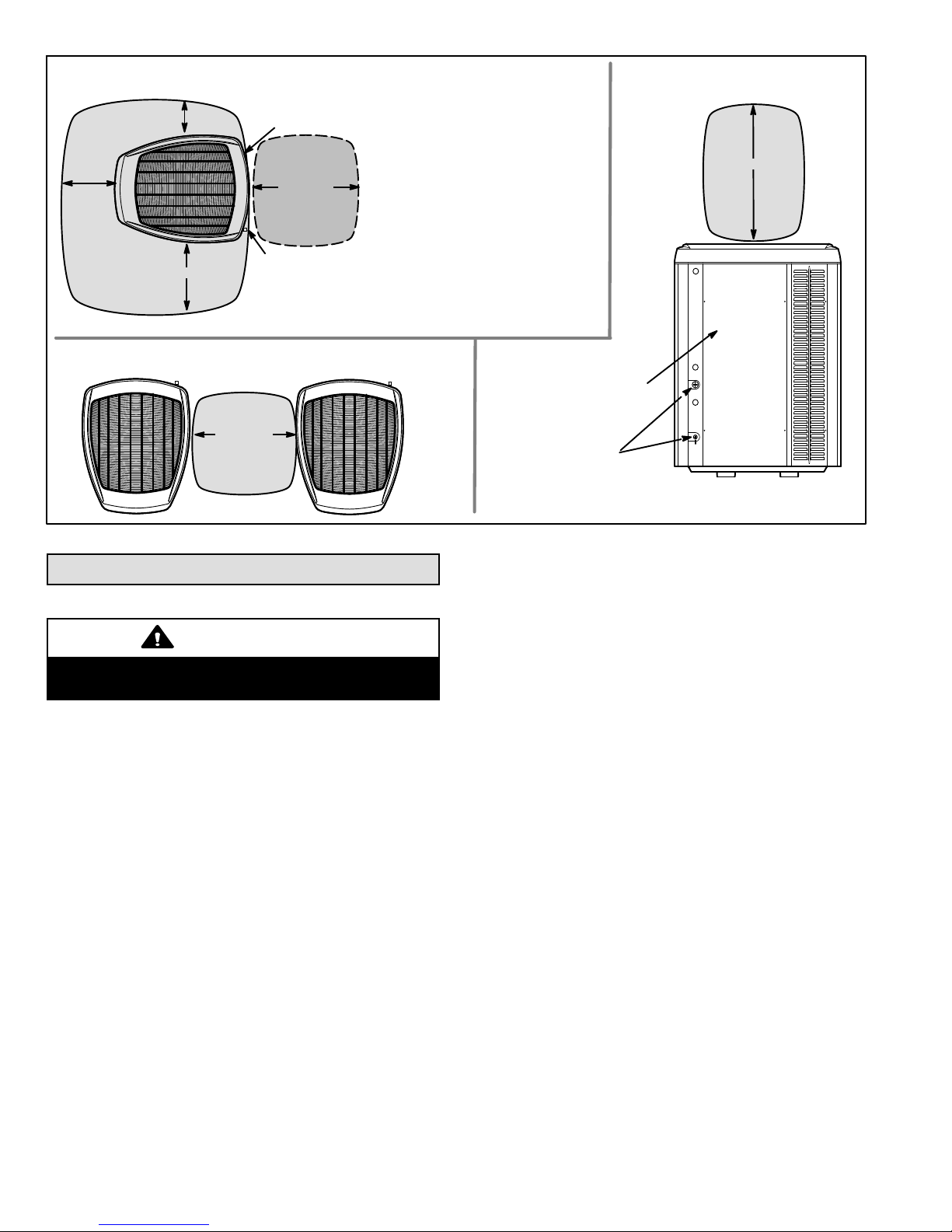
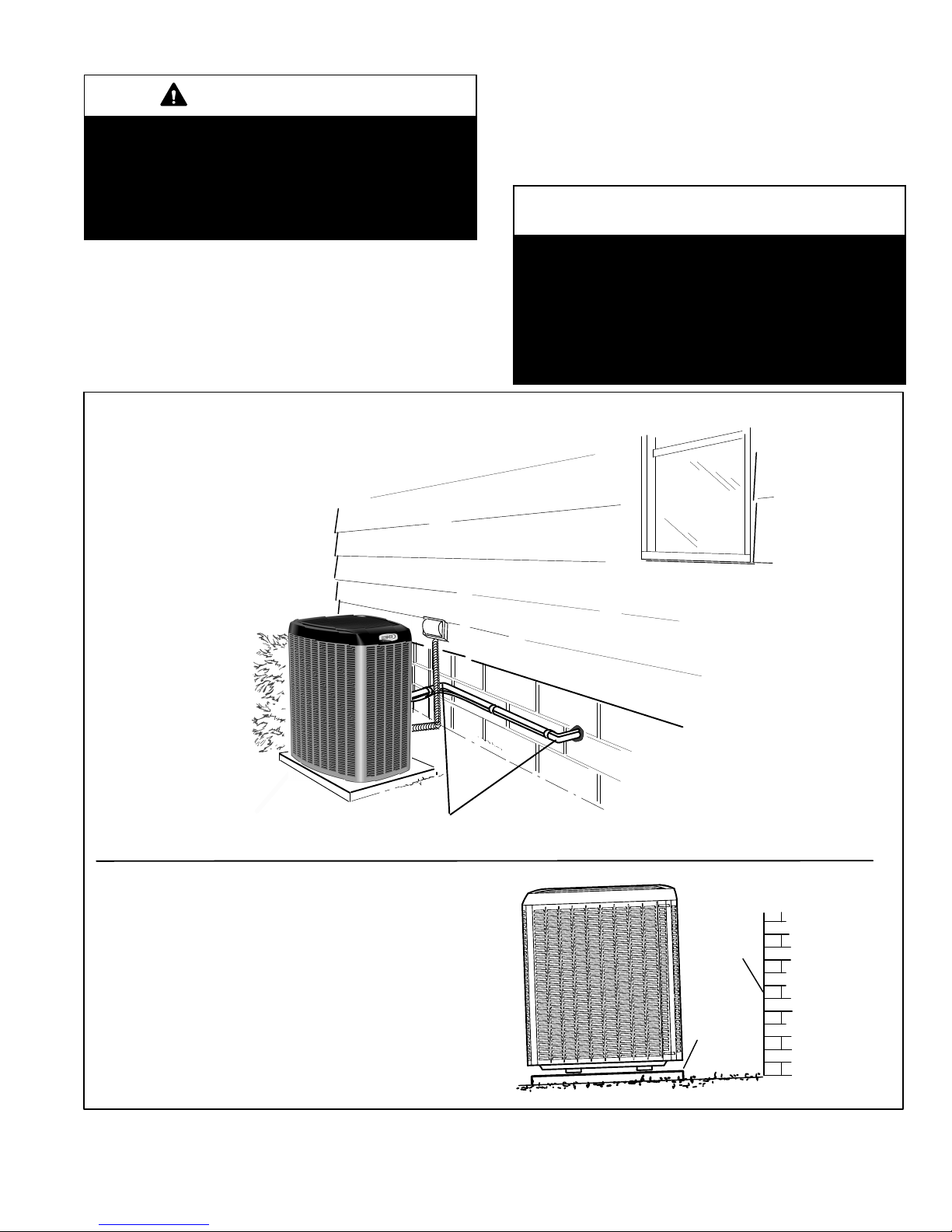
POSITIONING CONSIDERATIONS
Consider the following when positioning the unit:
S Some localities are adopting sound ordinances based
on the unit’s sound level registered from the adjacent
property, not from the installation property. Install the
unit as far as possible from the property line.
S When possible, do not install the unit directly outside
a window. Glass has a very high level of sound
transmission. For proper placement of unit in relation
to a window see the provided illustration in Figure 4,
Detail A.
PLACING UNIT ON SLAB
When installing unit at grade level, the top of the slab
should be high enough above grade so that water from
higher ground will not collect around the unit. The slab
should have a slope tolerance as described in Figure 4,
Detail B.
NOTE If necessary for stability, anchor unit to slab as
described in Figure 4, Detail D.
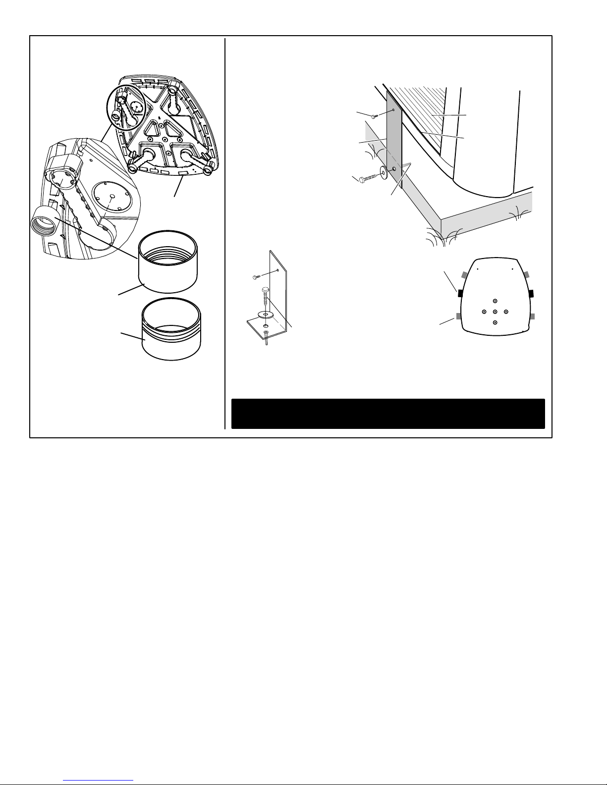
ELEVATING THE UNIT
Units are outfitted with elongated support feet as illustrated
in Figure 4, Detail C.
If additional elevation is necessary, raise the unit by
extending the height of the unit support feet. This may be
achieved by using a 2 inch (50.8mm) Schedule 40 female
threaded adapter.
The specified coupling will fit snuggly into the recessed
portion of the feet. Use additional 2 inch (50.8mm)
Schedule 40 male threaded adaptors which can be
threaded into the female threaded adaptors to make
additional adjustments to the level of the unit.
NOTE Keep the height of extenders short enough to
ensure a sturdy installation. If it is necessary to extend
further, consider a different type of field−fabricated
framework that is sturdy enough for greater heights.
Page 9
XC21
STABILIZING UNIT ON UNEVEN SURFACES
IMPORTANT
Unit Stabilizer Bracket Use (field−provided):
Always use stabilizers when unit is raised above the
factory height. (Elevated units could become unstable in
gusty wind conditions).
Stabilizers may be used on factory height units when
mounted on unstable an uneven surface.
With unit positioned at installation site, perform the
following
:
1. Remove two side louvered panels to expose the unit
base.
2. Install the brackets as illustrated in Figure 4, Detail D
using conventional practices.
3. Replace the panels after installation is complete.
ROOF MOUNTING
Install the unit a minimum of 6 inches (152 mm) above the
roof surface to avoid ice build−up around the unit. Locate
the unit above a load bearing wall or area of the roof that
can adequately support the unit. Consult local codes for
rooftop applications.
NOTICE
Roof Damage!
This system contains both refrigerant and oil. Some
rubber roofing material may absorbed oil and cause the
rubber to swell when it comes into contact with oil. The
rubber will then bubble and could cause leaks. Protect
the roof surface to avoid exposure to refrigerant and oil
during service and installation. Failure to follow this
notice could result in damage to roof surface.
TWO 90° ELBOWS INSTALLED IN LINE SET WILL
REDUCE LINE SET VIBRATION.
INSTALL UNIT LEVEL OR, IF ON A SLOPE, MAINTAIN SLOPE TOLERANCE
OF 2 DEGREES (OR 2 INCHES PER 5 FEET [50 MM PER 1.5 M]) AWAY
FROM BUILDING STRUCTURE.
MOUNTING
SLAB
BUILDING
STRUCTURE
GROUND LEVEL
Outside Unit Placement
Slab Mounting at Ground Level
INSTALL UNIT AWAY FROM WINDOWS
DETAIL A
DETAIL B
Figure 4. Placement, Slab Mounting and Stabilizing Unit
Page 10
XC21
LEG DETAIL
BASE
2" (50.8MM) SCH 40
FEMALE THREADED
ADAPTER
ONE BRACKET PER SIDE (MIN.); FOR EXTRA STABILITY, TWO
BRACKETS PER SIDE, 2" (50.8MM) FROM EACH CORNER.
CONCRETE SLAB USE TWO PLASTIC
ANCHORS (HOLE DRILL 1/4")
COIL
BASE PAN
CORNER POST
STABILIZING BRACKET (18 GAUGE
METAL 2" WIDTH; HEIGHT AS
REQUIRED)
Slab Side Mounting
#10 1/2" LONG SELF−DRILLING
SHEET METAL SCREWS
#10 1−1/4" LONG HEX HD SCREW
AND FLAT WASHER
MINIMUM ONE
PER SIDE
FOR EXTRA
STABILITY
Elevated Slab Mounting using Feet
Extenders
Stabilizing Unit on Uneven Surfaces
WOOD OR PLASTIC SLAB NO PLASTIC ANCHOR
(HOLE DRILL 1/8")
SAME FASTENERS AS
SLAB SIDE MOUNTING.
IMPORTANT To help stabilize an outdoor unit, some installations may require strapping the unit to the pad using brackets and anchors commonly
available in the marketplace.
DETAIL C
DETAIL D
2" (50.8MM) SCH 40
MALE THREADED
ADAPTER
Use additional 2" SCH 40 male threaded adapters
which can be threaded into the female threaded
adapters to make additional adjustments to the level of the unit.
STABILIZING BRACKET (18 GAUGE METAL
2" (50.8MM) WIDTH; HEIGHT AS
REQUIRED); BEND TO FORM RIGHT ANGLE
Deck Top Mounting
Figure 5. Placement, Slab Mounting and Stabilizing Unit
Page 11
XC21
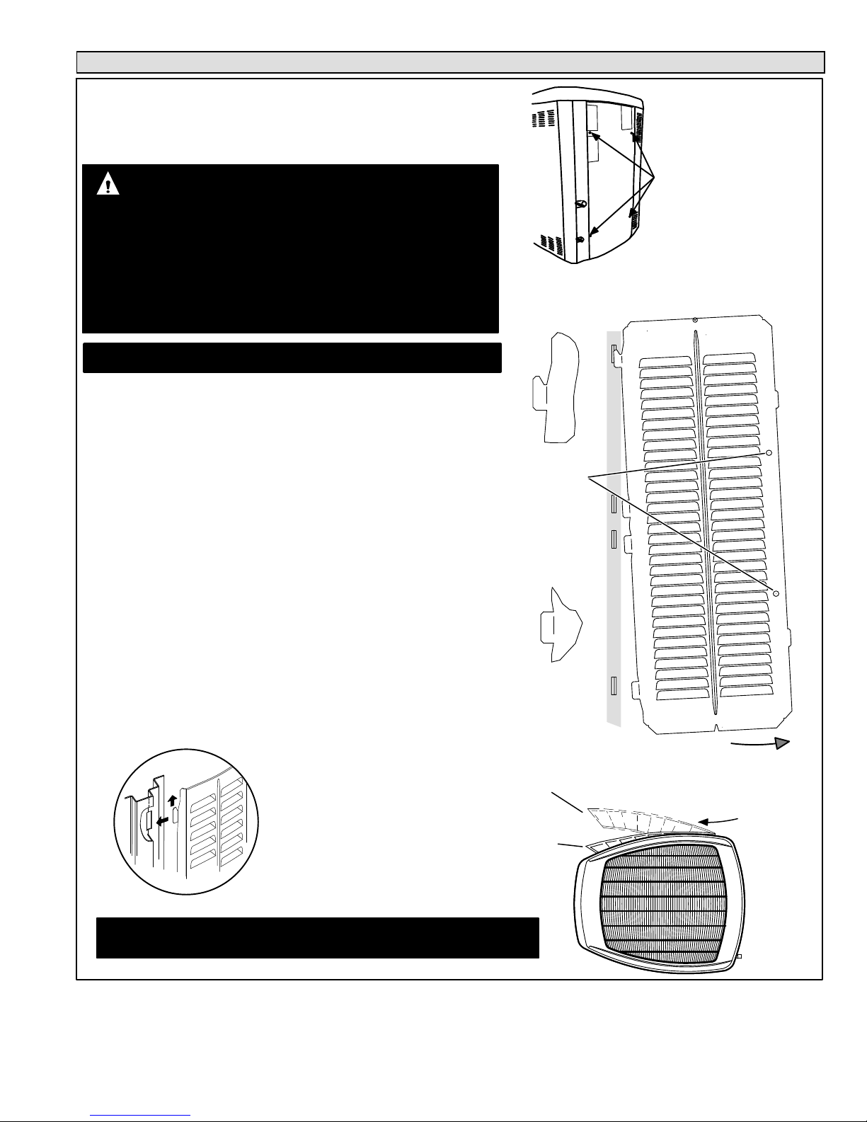
Removing and Installing Panels
REMOVE 4 SCREWS TO
REMOVE PANEL FOR
ACCESSING COMPRESSOR
AND CONTROLS.
POSITION PANEL WITH HOLES
ALIGNED; INSTALL SCREWS
AND TIGHTEN.
ACCESS PANEL REMOVAL
Removal and reinstallation of the access
panel is as illustrated.
Detail A
Detail C
Detail B
ROTATE IN THIS DIRECTION; THEN
DOWN TO REMOVE PANEL
SCREW
HOLES
LIP
PANEL SHOWN SLIGHTLY ROTATED TO ALLOW TOP TAB TO EXIT (OR ENTER) TOP SLOT
FOR REMOVING (OR INSTALLING) PANEL.
MAINTAIN MINIMUM PANEL ANGLE (AS CLOSE TO PARALLEL
WITH THE UNIT AS POSSIBLE) WHILE INSTALLING PANEL.
PREFERRED ANGLE FOR INSTALLATION
Detail D
ANGLE MAY BE TOO EXTREME
HOLD DOOR FIRMLY
ALONG THE HINGED SIDE
TO MAINTAIN FULLY−EN-
GAGED TABS
LOUVERED PANEL REMOVAL
Remove the louvered panels as follows:
1. Remove two screws, allowing the panel to swing open slightly.
2. Hold the panel firmly throughout this procedure. Rotate bottom corner of panel
away from hinged corner post until lower three tabs clear the slots as illustrated
in Detail B.
3. Move panel down until lip of upper tab clears the top slot in corner post as illus-
trated in Detail A.
LOUVERED PANEL INSTALLATION
Position the panel almost parallel with the unit as illustrated in Detail D with the screw
side as close to the unit as possible. Then, in a continuous motion:
1. Slightly rotate and guide the lip of top tab inward as illustrated in Detail A and C;
then upward into the top slot of the hinge corner post.
2. Rotate panel to vertical to fully engage all tabs.
3. Holding the panel’s hinged side firmly in place, close the right−hand side of the
panel, aligning the screw holes.
4. When panel is correctly positioned and aligned, insert the screws and tighten.
PANELS
ACCESS AND LOUVERED
IMPORTANT Do not allow panels to hang on unit by top tab. Tab is for align-
ment and not designed to support weight of panel.
IMPORTANT To help stabilize an outdoor unit, some installations may require
strapping the unit to the pad using brackets and anchors commonly available in the
marketplace.
To prevent personal injury, or damage to panels, unit or structure, be sure to observe the following:
While installing or servicing this unit, carefully stow all removed panels out of the
way, so that the panels will not cause injury to personnel, nor cause damage to
objects or structures nearby, nor will the panels be subjected to damage (e.g., being bent or scratched).
While handling or stowing the panels, consider any weather conditions, especially
windy conditions, that may cause panels to be blown around and battered.
WARNING
Figure 6. Removing and Installing Panels
Page 12
XC21
New or Replacement Line Set
REFRIGERANT LINE SET
This section provides information on installation or
replacement of existing line set. If new or replacement line
set is not being installed then proceed to Brazing
Connections on page 14.
IMPORTANT
Lennox highly recommends changing line set when
converting the existing system from HCFC−22 to
HFC−410A. If that is not possible and the line set is the
proper size as reference in table 2, use the procedure
outlined under Flushing the System on page 13.
If refrigerant lines are routed through a wall, then seal and
isolate the opening so vibration is not transmitted to the
building. Pay close attention to line set isolation during
installation of any HVAC system. When properly isolated
from building structures (walls, ceilings. floors), the
refrigerant lines will not create unnecessary vibration and
subsequent sounds. See Figure 7 for recommended
installation practices. Also, consider the following when
placing and installing a high−efficiency outdoor unit.
Liquid lines that meter the refrigerant, such as RFC1 liquid
lines, must not be used in this application. Existing line set
of proper size as listed in table 2 may be reused. If system
was previously charged with HCFC−22 refrigerant, then
existing line set must be flushed (see Flushing the System
on page 17).
Field refrigerant piping consists of liquid and vapor lines
from the outdoor unit to the indoor unit coil (braze
connections).
Table 2. Refrigerant Line Set Requirements
Models Liquid
Line
Vapor/
Suction
Line
L15 Line Set
−024, −036
and−048
3/8
(10mm)
7/8
(22mm)
L15 line set sizes are
dependent on unit match
up. See indoor unit
Engineering Handbook to
determine correct line set
sizes.
−060 3/8
(10mm)
1−1/8
(29mm)
Field Fabricated
NOTE Some applications may required a field provided 7/8" to
1−1/8" adapter.
NOTE When installing refrigerant lines longer than 50
feet, see the Lennox Refrigerant Piping Design and
Fabrication Guidelines, CORP. 9351−L9, or contact
Lennox Technical Support Product Applications for
assistance.
To obtain the correct information from Lennox, be sure to
communicate the following information:
S Model (XC21) and size of unit (e.g. −036).
S Line set diameters for the unit being installed as listed
in table 2 and total length of installation.
S Number of elbows vertical rise or drop in the piping.
IMPORTANT
Mineral oils are not compatible with HFC−410A. If oil must
be added, it must be a Polyol ester oil.
The compressor is charged with sufficient Polyol ester oil
for line set lengths up to 50 feet. Recommend adding oil to
system based on the amount of refrigerant charge in the
system. No need to add oil in system with 20 pounds of
refrigerant or less. For systems over 20 pounds − add one
ounce of every five pounds of refrigerant.
Recommended topping−off POE oils are Mobil EAL
ARCTIC 22 CC or ICI EMKARATEt RL32CF.
WARNING
Danger of fire. Bleeding the refrigerant
charge from only the high side may result
in the low side shell and suction tubing
being pressurized. Application of a
brazing torch while pressurized may
result in ignition of the refrigerant and oil
mixture − check the high and low
pressures before unbrazing.
WARNING
When using a high pressure gas such as
dry nitrogen to pressurize a refrigeration
or air conditioning system, use a regulator
that can control the pressure down to 1 or
2 psig (6.9 to 13.8 kPa).
CAUTION
Brazing alloys and flux contain materials which are
hazardous to your health.
Avoid breathing vapors or fumes from brazing
operations. Perform operations only in well ventilated
areas.
Wear gloves and protective goggles or face shield to
protect against burns.
Wash hands with soap and water after handling brazing
alloys and flux.
Page 13
XC21
ANCHORED HEAVY NYLON
WIRE TIE OR AUTOMOTIVE
MUFFLER-TYPE HANGER
STRAP LIQUID LINE TO
VAPOR LINE
WALL
STUD
LIQUID LINE
NON−CORROSIVE
METAL SLEEVE
VAPOR LINE − WRAPPED
IN ARMAFLEX
AUTOMOTIVE
MUFFLER-TYPE HANGER
REFRIGERANT LINE SET TRANSITION
FROM VERTICAL TO HORIZONTAL
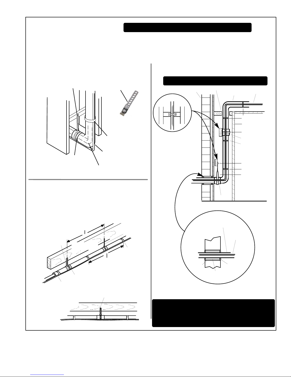
Line Set Isolation The following illustrations are
examples of proper refrigerant line set isolation:
STRAPPING
MATERIAL (AROUND
VAPOR LINE ONLY)
TAPE OR
WIRE TIE
WIRE TIE (AROUND
VAPOR LINE ONLY)
FLOOR JOIST OR
ROOF RAFTER
TAPE OR
WIRE TIE
To hang line set from joist or rafter, use either metal strapping material or anchored heavy nylon wire ties.
8 FEET (2.43 METERS)
STRAP THE VAPOR LINE TO THE
JOIST OR RAFTER AT 8 FEET (2.43
METERS) INTERVALS THEN STRAP
THE LIQUID LINE TO THE VAPOR LINE.
FLOOR JOIST OR
ROOF RAFTER
REFRIGERANT LINE SET INSTALLING
HORIZONTAL RUNS
NOTE Similar installation practices should be used if line set
is to be installed on exterior of outside wall.
PVC
PIPE
FIBERGLASS
INSULATION
CAULK
OUTSIDE
WALL
VAPOR LINE WRAPPED
WITH ARMAFLEX
LIQUID
LINE
OUTSIDE WALL
LIQUID LINE
VAPOR LINE
WOOD BLOCK
BETWEEN STUDS
STRAP
WOOD BLOCK
STRAP
SLEEVE
WIRE TIE
WIRE TIE
WIRE TIE
INSIDE WALL
REFRIGERANT LINE SET INSTALLING
VERTICAL RUNS (NEW CONSTRUCTION SHOWN)
INSTALLATION
LINE SET
NOTE Insulate liquid line when it is routed through areas where the
surrounding ambient temperature could become higher than the
temperature of the liquid line or when pressure drop is equal to or
greater than 20 psig.
NON−CORROSIVE
METAL SLEEVE
IMPORTANT Refrigerant lines must not contact structure.
NON−CORROSIVE
METAL SLEEVE
8 FEET (2.43 METERS)
IMPORTANT Refrigerant lines must not contact wall
WARNING Polyol ester (POE) oils used with HFC−410A
refrigerant absorb moisture very quickly. It is very important that the
refrigerant system be kept closed as much as possible. DO NOT
remove line set caps or service valve stub caps until you are ready
to make connections.
Figure 7. Line Set Installation
Page 14
XC21
Brazing Connections
Use the procedures outline in figures 8 and 9 for brazing
line set connections to service valves.
WARNING
Danger of fire. Bleeding the refrigerant
charge from only the high side may result
in pressurization of the low side shell and
suction tubing. Application of a brazing
torch to a pressurized system may result
in ignition of the refrigerant and oil mixture
− Check the high and low pressures
before applying heat.
WARNING
When using a high pressure gas such as
dry nitrogen to pressurize a refrigeration
or air conditioning system, use a regulator
that can control the pressure down to 1 or
2 psig (6.9 to 13.8 kPa).
CAUTION
Brazing alloys and flux contain materials which are
hazardous to your health.
Avoid breathing vapors or fumes from brazing
operations. Perform operations only in well−ventilated
areas.
Wear gloves and protective goggles or face shield to
protect against burns.
Wash hands with soap and water after handling brazing
alloys and flux.
IMPORTANT
Connect gauge set low pressure side to vapor line
service valve and repeat procedure starting at
paragraph 4 for brazing the liquid line to service port
valve.
IMPORTANT
Allow braze joint to cool before removing the wet rag
from the service valve. Temperatures above 250ºF can
damage valve seals.
IMPORTANT
Use silver alloy brazing rods with 5% minimum silver
alloy for copper−to−copper brazing. Use 45% minimum
alloy for copper−to−brass and copper−to−steel brazing.
WARNING
Fire, Explosion and Personal Safety
Hazard.
Failure to follow this warning could
result in damage, personal injury or
death.
Never use oxygen to pressurize or
purge refrigeration lines. Oxygen,
when exposed to a spark or open
flame, can cause fire and/or an explosion, that could result in property
damage, personal injury or death.
Page 15
XC21
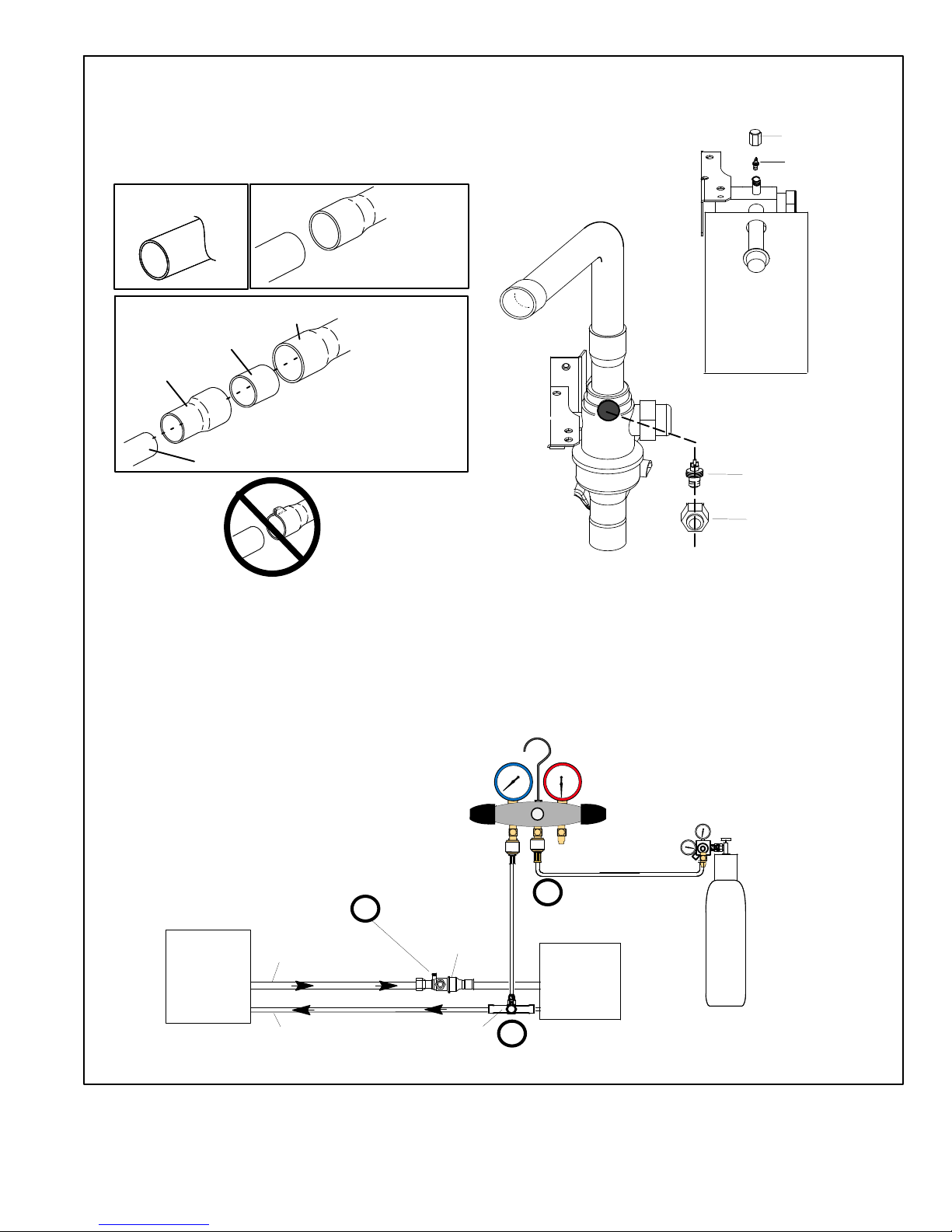
ATTACH THE MANIFOLD GAUGE SET FOR BRAZING
LIQUID AND SUCTION LINE SERVICE VALVES
OUTDOOR
UNIT
LIQUID LINE
SUCTION LINE
LIQUID LINE SERVICE
VALV E
SUCTION LINE
SERVICE VALVE
ATTACH
GAUGES
INDOOR
UNIT
SUCTION SERVICE PORT MUST BE OPEN AND
SERVICE PORT CORE REMOVED TO ALLOW
EXIT POINT FOR NITROGEN FLOW
A Connect gauge set low pressure side to liquid line
service valve (service port).
B Connect gauge set center port to bottle of nitrogen
with regulator.
C With valve core removed from the suction line service
port, nitrogen flow will have an exit point.
NITROGEN
HIGH
LOW
B
A
C
PIPING PANEL REMOVAL AND PREPARING LINE
SET
CAP AND CORE REMOVAL
Remove piping panel for easier access to service valves. Cut ends
of the refrigerant lines square (free from nicks or dents) and debur
the ends. The pipe must remain round. Do not crimp end of the line.
Remove service cap and core from both the suction and liquid line
service ports.
1
2
LIQUID LINE SERVICE VALVE
SERVICE PORT
CORE
SERVICE PORT CAP
SERVICE PORT
CORE
SERVICE
PORT CAP
CUT AND DEBUR
LINE SET SIZE MATCHES
SERVICE VALVE CONNECTION
COPPER TUBE
STUB
SERVICE VALVE
CONNECTION
REFRIGERANT LINE
DO NOT CRIMP SERVICE
VALVE CONNECTOR WHEN
PIPE IS SMALLER THAN
CONNECTION
REDUCER
3
SUCTION LINE SERVICE
VALV E
LINE SET SIZE IS SMALLER
THAN CONNECTION
Figure 8. Brazing Procedures
Page 16
XC21
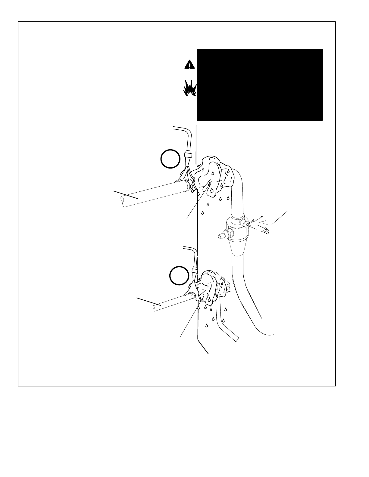
BRAZE LINE SET
Water saturated cloths must remain water saturated
throughout the brazing and cool−down process.
6
After all connections have been brazed, disconnect manifold gauge set from service ports. Apply additional water saturated cloths to both
services valves to cool piping. Once piping is cool, remove all water saturated cloths. Refer to the unit installation instructions for the next step in
preparing the unit.
PREPARATION FOR NEXT STEP
7
WRAP SERVICE VALVES
To help protect service valve seals during brazing, wrap water saturated cloths around service valve bodies and copper tube stubs. Use
additional water saturated cloths underneath the valve body to protect the base paint.
4
FLOW NITROGEN
Flow regulated nitrogen (at 1 to 2 psig) through the refrigeration
gauge set into the valve stem port connection on the liquid service
valve and out of the suction / vapor valve stem port. See steps 3A,
3B and 3C on previous page and below for manifold gauge setup.
5
SUCTION / VAPOR LINE
WHEN BRAZING LINE SET TO
SERVICE VALVES, POINT FLAME
AWAY FROM SERVICE VALVE.
WARNING
1. FIRE, PERSONAL INJURY, OR PROPERTY
DAMAGE will result if you do not wrap a water
saturated cloth around both liquid and suction line
service valve bodies and copper tube stub while
brazing in the line set! The braze, when complete,
must be quenched with water to absorb any
residual heat.
2. Do not open service valves until refrigerant lines
and indoor coil have been leak−tested and
evacuated. Refer to procedures provided in this
supplement.
LIQUID LINE
WATER SATURATED
CLOTHS
WATER SATURATED CLOTHS
A Braze liquid line to liquid line service valve.
B Braze suction / vapor line to suction / vapor service
valve.
6A
6B
SUCTION / VAPOR SERVICE PORT
MUST BE OPEN AND SERVICE PORT
CORE REMOVED TO ALLOW EXIT
POINT FOR NITROGEN FLOW
IMPORTANT Allow braze joint to cool. Apply
additional water saturated cloths to help cool
brazed joints. Do not remove water saturated
cloths until piping has cooled. Temperatures
above 250ºF will damage valve seals.
Figure 9. Brazing Procedures (Continued)
Page 17
XC21
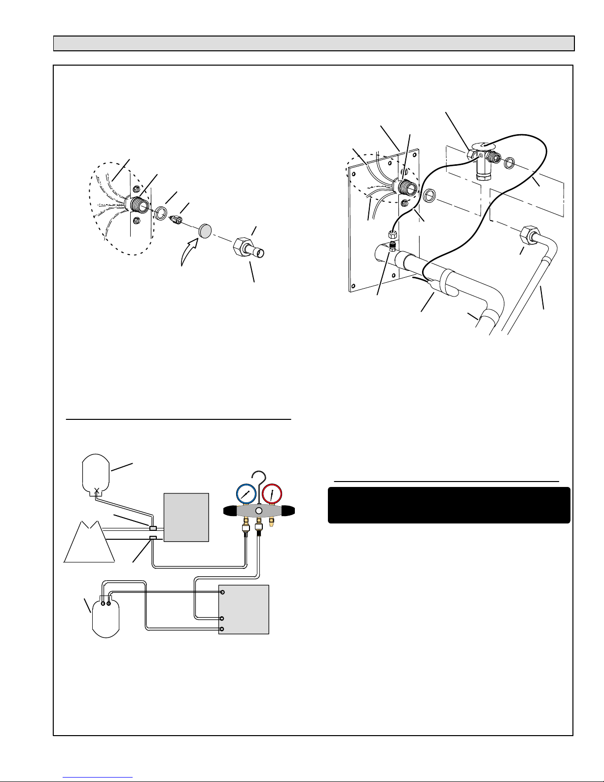
Flushing the System
SENSING
LINE
TEFLON RING
FIXED ORIFICE
(Uncased Coil Shown)
BRASS NUT
LIQUID LINE ASSEMBLY
(INCLUDES STRAINER)
LIQUID LINE ORIFICE HOUSING
DISTRIBUTOR TUBES
DISTRIBUTOR
ASSEMBLY
REMOVE AND DISCARD
WHITE TEFLON SEAL (IF
PRESENT)
A On fully cased coils, remove the coil access and plumbing panels.
B Remove any shipping clamps holding the liquid line and distributor
assembly.
C Using two wrenches, disconnect liquid line from liquid line orifice
housing. Take care not to twist or damage distributor tubes during
this process.
D Remove and discard fixed orifice, valve stem assembly if present
and Teflon washer as illustrated above.
E Use a field−provided fitting to temporary reconnect the liquid line to
the indoor unit’s liquid line orifice housing.
TYPICAL FIXED ORIFICE REMOVAL PROCEDURE
TYPICAL CHECK EXPANSION VALVE
REMOVAL PROCEDURE
TWO PIECE PATCH PLATE
(UNCASED COIL ONLY)
VAPOR
LINE
DISTRIBUTOR
ASSEMBLY
DISTRIBUTOR
TUBES
LIQUID
LINE
MALE EQUALIZER
LINE FITTING
EQUALIZER
LINE
CHECK
EXPANSION
VALV E
TEFLON
RING
(Uncased Coil Shown)
STUB END
TEFLON
RING
SENSING BULB
LIQUID LINE
ORIFICE
HOUSING
LIQUID LINE
ASSEMBLY WITH
BRASS NUT
A On fully cased coils, remove the coil access and plumbing panels.
B Remove any shipping clamps holding the liquid line and distributor
assembly.
C Disconnect the equalizer line from the check expansion valve
equalizer line fitting on the vapor line.
D Remove the vapor line sensing bulb.
E Disconnect the liquid line from the check expansion valve at the liquid
line assembly.
F Disconnect the check expansion valve from the liquid line orifice
housing. Take care not to twist or damage distributor tubes during this
process.
G Remove and discard check expansion valve and the two Teflon rings.
H Use a field−provided fitting to temporary reconnect the liquid line to
the indoor unit’s liquid line orifice housing.
LOW
HIGH
EXISTING
INDOOR
UNIT
GAUGE
MANIFOLD
INV ERTED HCFC−22
CYLINDER CONTAINS
CLE AN HCFC−22 TO BE
USED FOR FLUSHING.
LIQUID LINE SERVICE
VALV E
INLET
DISCHARGE
TANK
RETURN
CLOSED
OPENED
RECOVERY
CYLINDER
RECOVERY MACHINE
NEW
OUTDOOR
UNIT
VAPOR LINE
SERVICE VALVE
VAPOR
LIQUID
1
A Inverted HCFC−22 cylinder with clean refrigerant to the vapor
service valve.
B HCFC−22 gauge set (low side) to the liquid line valve.
C HCFC−22 gauge set center port to inlet on the recovery machine
with an empty recovery tank to the gauge set.
D Connect recovery tank to recovery machines per machine
instructions.
CONNECT GAUGES AND EQUIPMENT FOR
FLUSHING PROCEDURE
A
B
C
D
B
OR
FLUSHING LINE SET
A Set the recovery machine for liquid recovery and start the
recovery machine. Open the gauge set valves to allow the recovery machine to pull a vacuum on the existing system line set
and indoor unit coil.
B Invert the cylinder of clean HCFC−22 and open its valve to allow
liquid refrigerant to flow into the system through the vapor line
valve. Allow the refrigerant to pass from the cylinder and
through the line set and the indoor unit coil before it enters the
recovery machine.
C After all of the liquid refrigerant has been recovered, switch the
recovery machine to vapor recovery so that all of the HCFC−22
vapor is recovered. Allow the recovery machine to pull down to
0 the system.
D Close the valve on the inverted HCFC−22 drum and the gauge
set valves. Pump the remaining refrigerant out of the recovery
machine and turn the machine off.
The line set and indoor unit coil must be flushed with at least the
same amount of clean refrigerant that previously charged the system. Check the charge in the flushing cylinder before proceeding.
LINE SET AND INDOOR COIL (1 OF 2)
FLUSHING
1
2
3
CAUTION This procedure should not be performed on sys-
tems which contain contaminants (Example compressor burn
out.
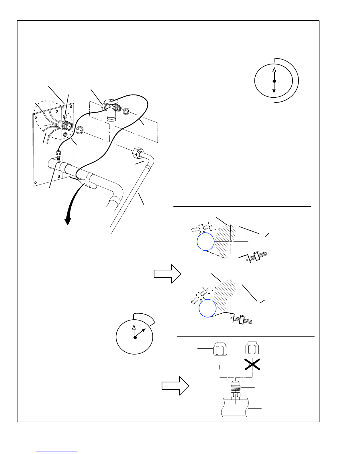
Page 18
XC21
A Attach the vapor line sensing bulb in the proper orientation
as illustrated to the right using the clamp and screws provided.
NOTE Confirm proper thermal contact between vapor line
and check expansion bulb before insulating the sensing bulb
once installed.
B Connect the equalizer line from the
check expansion valve to the equalizer
vapor port on the vapor line. Finger tighten the flare nut plus 1/8 turn (7 ft−lbs) as
illustrated below.
The check expansion valve unit can be installed internal or
external to the indoor coil. In applications where an uncased
coil is being installed in a field−provided plenum, install the
check expansion valve in a manner that will provide access for
field servicing of the check expansion valve. Refer to below
illustration for reference during installation of check expansion
valve unit.
TYPICAL CHECK EXPANSION VALVE INSTALLATION PROCEDURE
TWO PIECE
PATCH PLATE
(UNCASED
COIL ONLY)
VAPOR
LINE
LIQUID LINE
ORIFICE
HOUSING
DISTRIBUTOR
TUBES
LIQUID LINE
MALE EQUALIZER LINE
FITTING (SEE
EQUALIZER LINE
INSTALLATION FOR
FURTHER DETAILS)
SENSING
LINE
EQUALIZER
LINE
CHECK
EXPANSION
VALV E
TEFLON
RING
(Uncased Coil Shown)
SENSING BULB INSULATION IS REQUIRED
IF MOUNTED EXTERNAL TO THE COIL
CASING. SENSING BULB INSTALLATION
FOR BULB POSITIONING.
STUB
END
TEFLON
RING
LIQUID LINE
ASSEMBLY WITH
BRASS NUT
DISTRIBUTOR
ASSEMBLY
This outdoor unit is designed for use in systems that use check expansion valve metering device. See the Lennox XC21 Engineering Hand-
book for approved check expansion valve kit match−ups and application information.
A Remove the field−provided fitting that temporary reconnected the liq-
uid line to the indoor unit’s distributor assembly.
B Install one of the provided Teflon rings around the stubbed end of the
check expansion valve and lightly lubricate the connector threads and
expose surface of the Teflon ring with refrigerant oil.
C Attach the stubbed end of the check expansion valve to the liquid line
orifice housing. Finger tighten and use an appropriately sized wrench
to turn an additional 1/2 turn clockwise as illustrated in the figure
above, or 20 ft−lb.
D Place the remaining Teflon washer around the other end of the check
expansion valve. Lightly lubricate connector threads and expose surface of the Teflon ring with refrigerant oil.
E Attach the liquid line assembly to the check expansion valve. Finger
tighten and use an appropriately sized wrench to turn an additional 1/2
turn clockwise as illustrated in the figure above or 20 ft−lb.
ON 7/8" AND LARGER LINES,
MOUNT SENSING BULB AT
EITHER THE 4 OR 8 O’CLOCK
POSITION. NEVER MOUNT ON
BOTTOM OF LINE.
12
ON LINES SMALLER THAN 7/8",
MOUNT SENSING BULB AT
EITHER THE 3 OR 9 O’CLOCK
POSITION.
12
BULB
VAPOR LINE
VAPOR LINE
NOTE NEVER MOUNT ON BOTTOM OF LINE.
BULB
BULB
BULB
VAPOR LINE
FLARE NUT
COPPER FLARE
SEAL BONNET
MALE BRASS EQUALIZER
LINE FITTING
FLARE SEAL CAP
OR
1
2
3
4
5
6
7
8
9
10
11
12
1/2 TURN
SENSING BULB INSTALLATION
EQUALIZER LINE INSTALLATION
1
2
3
4
5
6
7
8
9
10
11
12
1/8 TURN
FLUSHING LINE SET AND INDOOR COIL (2 OF 2)
4
A Remove and discard either the flare seal cap or flare nut
with copper flare seal bonnet from the equalizer line port
on the vapor line as illustrated in the figure to the right.
B Remove and discard either the flare seal cap or flare nut
with copper flare seal bonnet from the equalizer line port
on the vapor line as illustrated in the figure to the right.
 Loading...