

Page 1
E N G I N E E R I N G D A TA
A I R C O N D I T I O N E R S
XC17
DAVE LENNOX SIGNATURE® COLLECTION
R-410A - SilentComfort™ Technology
Bulletin No. 210585
January 2011
Supersedes Bulletin November 2010
MODEL NUMBER IDENTIFICATION
X C 17 - 036 - 230 - 2
Refrigerant Type
X = R-410A
Unit Type
C = Air Conditioner
Series
SEER up to 18.00
2 to 5 Tons
Cooling Capacity - 21,800 to 59,000 Btuh
Minor Revision Number
Voltage
230 = 208/230V-1phase-60hz
Nominal Cooling Capacity
024 = 2 tons
030 = 2.5 tons
036 = 3 tons
042 = 3.5 tons
048 = 4 tons
060 = 5 tons
Page 2
FEATURES
Contents
AHRI System Matches................................................14
Dimensions .................................................................12
Electrical Data.............................................................10
Features........................................................................2
Controls ........................................................................4
Field Wiring .................................................................11
Installation Clearances ...............................................11
Model Number Identication .........................................1
Optional Accessories ..................................................10
Outdoor Sound Data ...................................................11
Specications..............................................................10
Sunsource® Home Energy System - Components .......7
Equipment Warranty
Compressor - limited warranty for ten years in
residential installations and ve years in non-residential
installations.
All other covered components - ten years in
residential installations and one year in non-residential
installations.
Refer to Lennox Equipment Limited Warranty certicate
included with unit for specic details.
K
B
I
C
H
G
E
J
F
D
A
ApplicationS
SEER up to 18.00
2 through 5 ton.
Sound levels as low as 62 dB.
Single phase power supply.
SunSource® Solar-Ready (with optional Lennox Solar
Subpanel).
Vertical air discharge allows concealment behind shrubs
at grade level or out of sight on a roof.
Matching add-on furnace indoor coils or air handlers
provide a wide range of cooling capacities and
applications. See AHRI System Matches.
See Indoor Coils and Air Handlers tab sections for data.
Units shipped completely factory assembled, piped, and
wired. Each unit is test operated at the factory insuring
proper operation.
Installer must set air conditioner, connect refrigerant
lines, and make electrical connections to complete job.
Approvals
Certied in accordance with USE certication program
which is based on AHRI Standard 210/240-2008.
Sound rated in Lennox reverberant sound test room
in accordance with test conditions included in AHRI
Standard 270-2008.
Tested in the Lennox Research Laboratory
environmental test room.
Rated according to U.S. Department of Energy (DOE)
test procedures.
Air conditioners and components within bonded for
grounding to meet safety standards for servicing
required by ETL, NEC and CEC.
Units are ETL listed for the US and Canada.
ISO 9001 Registered Manufacturing Quality System.
EnErgy Star® certied units are designed to use less
energy, help save money on utility bills, and help protect
the environment. Many Lennox home comfort systems
meet EnErgy Star requirements when used with
matching components.
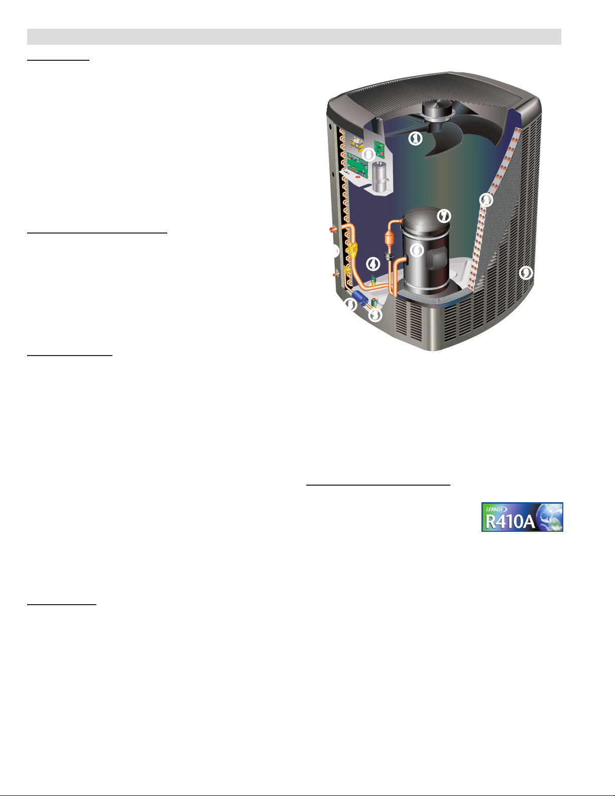
REFRIGERATION SYSTEM
R-410A Refrigerant
Non-chlorine, ozone friendly, R-410A.
Unit pre-charged with refrigerant.
See Specication table.
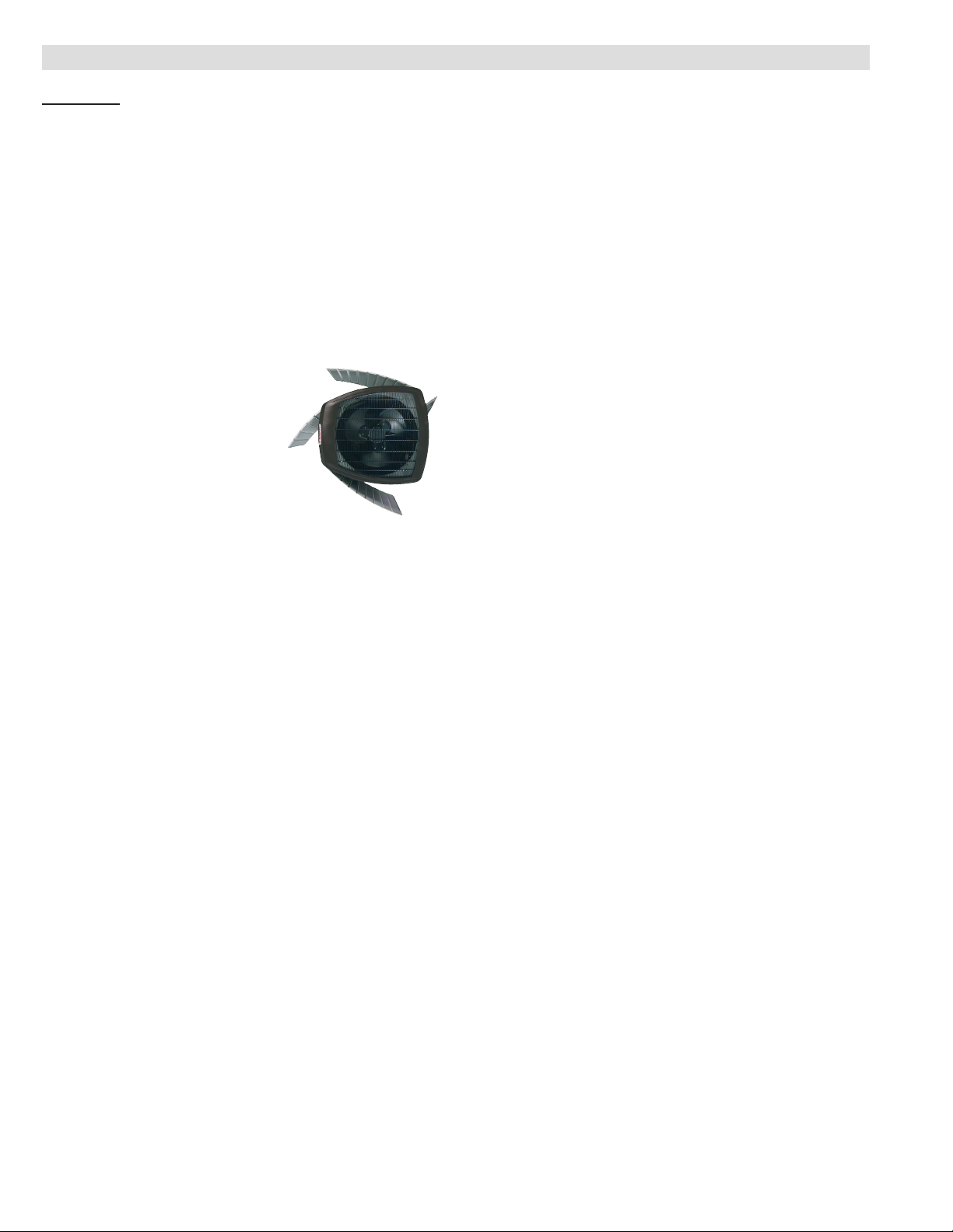
Condenser Fan with SilentComfort™ Technology
B
Specially-designed, SilentComfort fan guard uses
Passive Vortex Suppression to reduce air noise.
Corrosion-resistant PVC (polyvinyl chloride) coated
steel wire.
Specially designed fan blades reduce operating
sound levels. Direct drive fan moves large air volumes
uniformly through entire condenser coil for high
refrigerant cooling capacity.
Vertical air discharge minimizes operating sounds and
eliminates damage to lawn and shrubs.
Fan motor is inherently protected.
Motor totally enclosed for maximum protection from
weather, dust and corrosion.
Fan service access accomplished by removal of fan
guard.
XC17 - 2 to 5 Ton Air Conditioner / Page 2
Page 3
FEATURES
REFRIGERATION SYSTEM (CONTINUED)
Copper Tube/Enhanced Fin Coil
C
Lennox designed and fabricated coil.
Ripple-edged aluminum ns.
Copper tube construction.
Lanced ns provide maximum exposure of n surface to
air stream resulting in excellent heat transfer.
Fin collars grip tubing for maximum contact area.
Flared shoulder tubing connections/silver soldering
construction.
Coil is factory tested under high pressure to insure
leakproof construction.
Entire coil is accessible for cleaning.
High Pressure Switch
D
Shuts off unit if abnormal operating conditions cause the
discharge pressure to rise above setting.
Protects compressor from excessive condensing
pressure.
Manual reset.
Low Pressure Switch
E
Shuts off unit if suction pressure falls below setting.
Provides loss of charge and freeze-up protection.
Automatic reset.
Hi-Capacity Liquid Line Drier
F
Factory installed in the liquid line, the drier traps
moisture or dirt that could contaminate the refrigerant
system.
100% molecular-sieve bead type drier.
OPTIONS
Expansion Valve Kits
Must be ordered extra and eld installed on certain
evaporator units. See TXV Usage table.
Chatleff style tting.
Freezestat
Installs on or near the discharge line of the evaporator
or on the suction line.
Senses suction line temperature and cycles the
compressor off when suction line temperature falls
below it’s setpoint.
Opens at 29°F and closes at 58°F.
Refrigerant Line Kits
Refrigerant lines (suction & liquid) are shipped
refrigeration clean. Lines are cleaned, dried,
pressurized, and sealed at factory.
Suction line fully insulated.
L15 lines are stubbed at both ends.
See Specications table for selection.
Not available for -060 model and must be eld
fabricated.
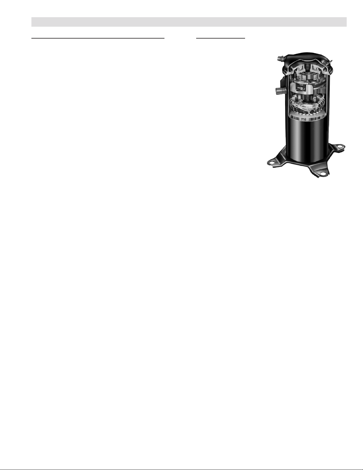
COMPRESSOR
Scroll Compressor
G
Compressor features
high efciency with
uniform suction ow,
constant discharge ow
and high volumetric
efciency and quiet
operation.
Compressor consists
of two involute spiral
scrolls matched together
to generate a series of
crescent shaped gas
pockets between them.
During compression, one
scroll remains stationary
while the other scroll
orbits around it.
Gas is drawn into the
outer pocket, the pocket is sealed as the scroll rotates.
As the spiral movement continues, gas pockets are
pushed to the center of the scrolls. Volume between the
pockets is simultaneously reduced.
When pocket reaches the center, gas is now at high
pressure and is forced out of a port located in the center
of the xed scrolls.
During compression, several pockets are compressed
simultaneously resulting in a smooth continuous
compression cycle.
Continuous ank contact, maintained by centrifugal
force, minimizes gas leakage and maximizes efciency.
Scroll compressor is tolerant to the effects of slugging
and contaminants. If this occurs, scrolls separate,
allowing liquid or contaminants to to be worked toward
the center and discharged.
Low gas pulses during compression reduces
operational sound levels.
Compressor motor is internally protected from
excessive current and temperature.
Compressor is installed in the unit on resilient rubber
mounts for vibration free operation.
Factory installed crankcase heater.
Crankcase Heater
Crankcase heater prevents migration of liquid
refrigerant into compressor and ensures proper
compressor lubrication.
Compressor Sound Cover
H
A Lennox-exclusive, sand-lled, polypropylene
copolymer, compressor cover dramatically reduces
compressor sound levels.
XC17 - 2 to 5 Ton Air Conditioner / Page 3
Page 4
FEATURES
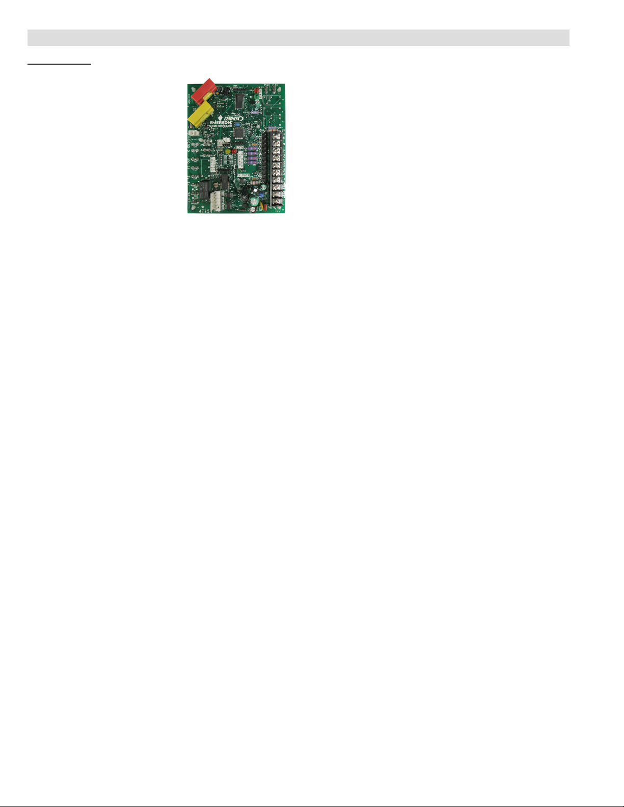
CONTROLS
icomfort™ Control
I
Advanced icomfort™ control
communicates information about
various operating parameters
in the air conditioner to the
optional icomfort™ Touch
Communicating Thermostat to
constantly maintain the highest
level of comfort, performance and
efciency available.
Connections for connecting a
conventional heating/cooling
thermostat are also provided on the control.
Auto Conguration - On start-up the control
automatically sends a description of the unit to
the optional icomfort™ Touch Communicating
Thermostat to automatically congure the number of
stages and features available.
Control also features:
• Compressor anti-short cycle delay (5 minutes).
• High and low pressure switch monitoring with
provisions for lockout.
• Five-Strike lockout protection protects compressor.
• Discharge line and sensor monitoring.
• Lennox Humiditrol® Whole Home Dehumidication
System (EDA) compatible.
• EEPROM storage of all local congurations.
Lennox Systems Operations Monitor
(icomfort™ Control Feature)
Onboard Lennox® Systems Operations Monitor (LSOM)
provides detailed information for proper preventative
maintenance and fast, easy servicing.
Displays the most common fault conditions (electrical
and mechanical) through the icomfort™ Touch
communicating thermostat or through the ALERT
and TRIP lights on the control. ALERT LED (yellow) communicates an abnormal system condition through a
unique ash code. The ALERT LED will ash a number
of times consecutively, pause and then repeat the
process. The number of consecutive ashes, dened
as the Flash Code, correlates to a particular abnormal
condition. The codes can indicate one of the following:
long run time, system pressure trip (discharge or suction
pressure out-of-limits or compressor overloaded), short
cycling, locked rotor, open circuit, open start circuit
(current present only in run circuit), open run circuit
(current present only in start circuit), welded contactor
(compressor runs continuously), or low voltage (control
circuit < 17VAC). TRIP LED (red) - indicates there is a
demand signal from the thermostat but no current to the
compressor is detected by the monitor.
OPTIONS
Compressor Low Ambient Cut-Off
Non-adjustable switch (low ambient cut-out) prevents
compressor operation when outdoor temperature is
below 35°F.
Compressor Hard Start Kit
Single-phase units are equipped with a PSC
compressor motor.
This type of motor normally does not need a potential
relay and start capacitor.
In conditions such as low voltage, kit may be required to
increase the compressor starting torque.
Indoor Blower Off Delay Relay
Delays the indoor blower-off time during the cooling
cycle. Required if outdoor unit is used with a
conventional heating-cooling thermostat and air handler
(non-icomfort control system). See furnace or air
handler specications to determine if relay is needed.
Indoor Blower Speed Relay Kit
Relay kit provides optimum humidity control conditions
by automatically reducing indoor blower speed during
continuous fan or rst-stage compressor operation.
Low Ambient Kit
Air conditioner will operate satisfactorily down to 45°F
outdoor air temperature without any additional controls.
Kit can be added in the eld enabling unit to operate
properly down to 30°F.
A Freezestat should be installed on compressors
equipped with a low ambient kit.
A Compressor Low Ambient Cut-Off should be added to
terminate compressor operation below recommended
operation conditions.
XC17 - 2 to 5 Ton Air Conditioner / Page 4
Page 5
INDOOR RH 26%
WED AN 21 12:35AM
MODE
ON
AUTO
HOME SCHEDULE OPTIONS
SETAT
SETAT
HEAT
COOL
SCHED
FEATURES
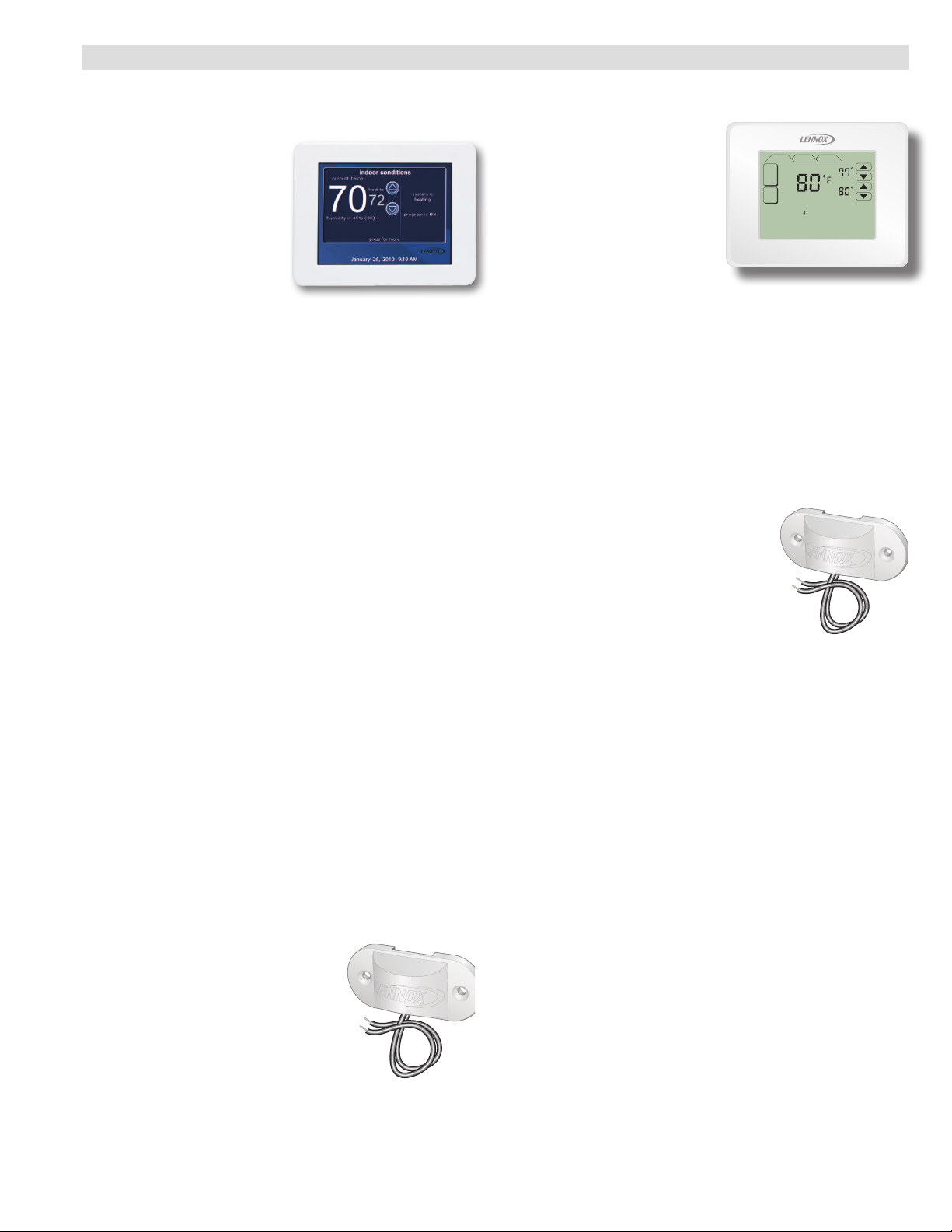
icomfort™ Touch Communicating Thermostat
(part of the icomfort Residential Communicating
Control System)
The icomfort™ Touch
communicating thermostat
recognizes and connects to
all icomfort enabled products
to automatically congure
and control the system
(based on user-specied
settings) for the highest level
of comfort, performance and
efciency. Also recognizes model and serial number
information for icomfort-enabled products to simplify
installation.
Large full color touchscreen - no hidden buttons or
doors.
A simple easy-to-use menu-driven touchscreen allows
complete system conguration. Scheduled maintenance
alerts, system warnings and troubleshooting are also
displayed in simple English on thermostat screen.
Non-icomfort-enabled products can easily be added and
controlled by the icomfort Touch thermostat.
A tabbed interface lists all programming options on the
screen.
Installer setup screens allow quick and simple system
conguration without a manual, Installer can also run
tests on complete system or individual components for
easy maintenance and troubleshooting.
Serial communications bus (RSBus), with less wiring
than a conventional heating/cooling system, allows
system communication. Uses 4-wire, 18-gauge
standard thermostat wiring.
See the icomfort™ Touch Communicating Thermostat
Engineering Handbook bulletin in the Controls section
for more information.
Discharge Air Temperature Sensor
Used with icomfort Touch thermostat.
When installed in the supply air plenum, the discharge
air temperature sensor allows the icomfort thermostat
to control low and high stage heating temperatures.
Sensor is auto-detected when connected to thermostat.
Remote Outdoor Sensor
Used with icomfort Touch thermostat.
When installed outdoors, sensor
allows thermostat to display outdoor
temperature. Sensor is auto-detected
when connected to thermostat.
NOTE - Sensor is required for
Humiditrol® applications.
ComfortSense® 7000 Touchscreen Thermostat
Electronic 7-day, universal, multi-stage, programmable,
touchscreen thermostat.
4 Heat/2 Cool.
Auto-changeover.
Controls humidity during
cooling mode.
Offers enhanced capabilities
including humidication /
dehumidication / dewpoint
measurement and control, Humiditrol® control, and
equipment maintenance reminders.
Easy-to-use, menu driven thermostat with a back-lit,
LCD touchscreen.
Remote outdoor temperature sensor (optional) allows
the thermostat to display outdoor temperature. Required
in dual-fuel and Humiditrol® applications.
See the ComfortSense® 7000 Engineering Handbook
bulletin in the Controls section for more information.
Outdoor Temperature Sensor
Used with ComfortSense 7000
thermostat.
When installed outdoors, sensor
allows thermostat to display outdoor
temperature. Sensor is auto-detected
when connected to thermostat.
NOTE - Sensor is required for
Humiditrol® applications.
Thermostat
Thermostat is not furnished with unit.
See Thermostat bulletins in Controls Section and
Lennox Price Book for selection.
XC17 - 2 to 5 Ton Air Conditioner / Page 5
Page 6
FEATURES
Cabinet
Heavy-gauge steel construction
Pre-painted cabinet nish.
Painted base section.
Control box is conveniently located with all controls
factory wired.
Large removable panel provides service access.
Drainage holes are provided in base section for
moisture removal.
High density polyethylene unit support feet raise the
unit off of the mounting surface, away from damaging
moisture.
SmartHinge™ Louvered Coil Protection
J
Steel louvered panels provides
complete coil protection.
Panels are hinged to allow easy
cleaning and servicing of coils.
Panels may be completely
removed.
Interlocking tabs and slots assure
tight t on cabinet.
Refrigerant Line Connections, Electrical Inlets and
K
Service Valves
Suction and liquid lines are located on corner of unit
cabinet and are made with sweat connections. See
dimension drawing.
Fully serviceable brass service valves prevent corrosion
and provide access to refrigerant system. Suction valve
can be fully shut off, while liquid valve may be front
seated to manage refrigerant charge while servicing
system.
Suction and liquid line service valves and gauge ports
are located inside the cabinet.
Refrigerant line connections and eld wiring inlets
are located in one central area of the cabinet. See
dimension drawing.
XC17 - 2 to 5 Ton Air Conditioner / Page 6
Page 7
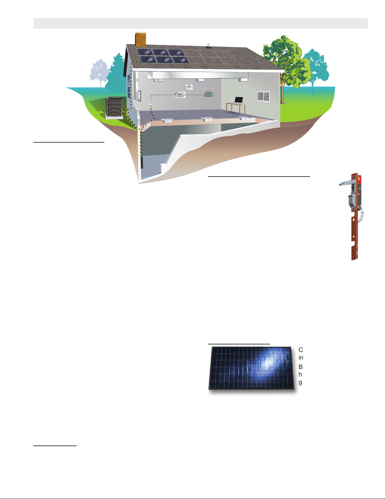
SUNSOURCE® HOME ENERGY SYSTEM - COMPONENTS
Solar Modules
Future
Modules
Air Conditioner
or Heat Pump
Standard
Outlet
Communication
Gateway
Performance
Monitoring
Website
Broadband
Internet
Connection
Electrical
Panel
Unit
SYSTEM OVERVIEW
All Dave Lennox Signature
Collection air conditioners and
heat pumps are equipped at the
factory for upgrading to the
SunSource® Home Energy System.
Units can be upgraded at the time of installation or in
the future.
Solar energy is rst used to meet cooling/heating
demands. When the cooling/heating system is not
operating, the system powers lighting, appliances and
other electronic devices in the home. And in some
locations, any surplus power is sent back to the utility
company for a possible credit (check with your local
utility company for availability).
The SolarSync™ Package consists of the following
components:
• Lennox Solar Subpanel eld installed in a Dave
Lennox Signature® Collection air conditioner or heat
pump unit.
• Solar Modules (1 to 15 may be used to vary the
amount of electricity generated).
• Envoy Communications Gateway that monitors home
energy usage.
All components must be ordered separately.
Wiring from the roof mounted solar modules is routed to
the outdoor unit. From there power travels to the home
electrical service panel using the existing outdoor unit
power wiring.
NOTE - Refer to separate Engineering Handbook
Bulletin for the SunSource® Home Energy System
for more detailed information. See section Solar - Kits/
Accessories.
Also refer to SunSource® Home Energy System
Applications and Design Guidelines Manual (Corp.
1021-L3) for complete information on designing, sizing
and installing a complete system.
APPROVALS
The SunSource® Home Energy System meets the
requirements for federal tax credits listed under the
U.S. Emergency Economic Stabilization Act of 2008,
covering 30% of the cost of the solar modules, including
installation.
®
LENNOX® SOLAR SUBPANEL
The Lennox® Solar Subpanel replaces the
factory piping panel on the outdoor unit and
provides circuit breaker protection and power
entry for both HVAC (line) and solar power
wiring.
Subpanel is equipped with separate circuit
breakers for both HVAC (line) voltage and
solar power.
Equipped with pigtail connections for easy
eld wiring.
Subpanel is an ETL listed accessory.
Split design (upper/lower panel) allows installation on
different size outdoor units. Subpanel is furnished with
three separate lower panels. See Outdoor Unit Usage
table for correct lower panel size.
Note - Subpanel is not backwards compatible with older
Dave Lennox Signature® Collection outdoor units.
Disconnects for HVAC (line) and solar power wiring are
not furnished and must be eld provided.
SOLAR MODULES
AC power synchronized to the utility grid.
Modules operate independently from each other
allowing modules that are not shaded or dirty to operate
with optimum performance.
Racking system is built-in to the module frame.
Painted at black frame.
Four modules furnished per order.
Solar modules are UL listed, CSA certied and meet
National Electrical Code requirements.
Converts solar energy
into electricity.
Built-in racking
hardware, wiring,
grounding and
microinverters.
Microinverters produce
XC17 - 2 to 5 Ton Air Conditioner / Page 7
Page 8
SUNSOURCE® HOME ENERGY SYSTEM - COMPONENTS
SOLAR MODULES (CONTINUED)
Roof Mounting Kits
Several roof mounting kits for mounting Solar Modules
are available for a variety of different roof styles. All
kits contain sufcient hardware for mounting four solar
modules.
Composition (Asphalt) Shingle Roof Mounting Kit
Kit includes: (6 each) Composition ashing mounts,
serrated L-brackets, solar module splices, serrated
T-bolts, ange nuts, lag bolts, fender washers, (2) wire
spring clips, (1) ground lug w/screw, (1) installation
wrench.
S or Barrel Tile Roof Mounting Kit
Kit includes: (6 each) S/Barrel tile mounts, mount foots,
6 in. aluminum posts, serrated L-brackets, solar module
splices, serrated T-bolts, ange nuts, washers, hex
bolts, (2) Wire spring clips, (1) ground lug w/screw, (1)
installation wrench.
Flat (Cement) Tile Roof Mounting Kit
Kit includes: (6 each) at tile bracket, universal tile
bracket, solar module splices, T-bolts, (36) ange nuts,
(12) fender washers, (12) washers, (12) lag bolts, (2)
wire spring clips, (1) ground lug w/screw, (1) installation
wrench.
Standing Seam Roof Mounting Kit
Kit includes: (8 each) S-5!™ standing seam clamps,
ip clips, mounting spacers, hex bolts, (6) solar module
splices, (2) wire spring clips, (1) ground lug w/screw, (1)
installation wrench.
Installation Kits and Tools
AC System Kit (Required - One per each outdoor unit)
Kit includes interconnection cable required to adapt
microinverter cable to eld wiring. Includes plug
to microinverter and pigtails for eld wiring. Also
includes the end cap to place on the last microinverter
connection in the row. One kit required per outdoor unit.
Kit contains 6 ft. AC interconnection cable and end cap.
AC 6 Foot Extension Cable
Six foot extension cable for connecting one row of
modules to the next if they are further than the standard
interconnection cable can reach (second row above or
below, etc.). Only required for multiple rows.
Rooftop Junction Box
Flash mounted rooftop junction box is used to transition
from interconnection cable to wiring/conduit to the
outside HVAC unit. Use one for each outdoor unit.
Professional Installer Tool Kit
Installer tools to aid in installation. Includes driver to
tighten splices with ratchet from opposite side of module
(in place of wrench) and step block to support module
until splices and mounting points are installed.
Includes (2) Splice drivers and (2) Step Blocks
Solar Module Splices
Required if installing a second row of solar modules
above or below an existing row or adding additional 4
packs of modules end to end.
Splices used in top and bottom applications are not a
grounding component and only act as a rigid attachment
to support the upper or lower module frame of the
second row to the module frame of the existing row.
Allows for fewer roof penetrations by supporting the
upper and lower solar modules in a two-row application
with a common roof mount in-between.
Kit contains 10 splices.
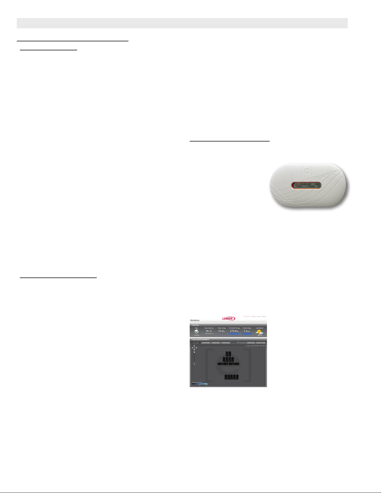
SYSTEM MONITORING
Envoy Communications Gateway
The Envoy Communications Gateway monitors
microinverter (on solar
modules) performance
and can be connected
to a broadband internet
connection to send
data to the Enphase
Enlighten™ web site
for online monitoring by the homeowner. The Envoy
Communications Gateway is not required, but must be
used if system performance monitoring is desired.
Limited system monitoring is also available locally with
the Envoy Communications Gateway and a personal
computer if no internet connection is available.
Various Event Messages are also available when
monitoring the system via a personal computer locally.
Contents - (1) Envoy Communications Gateway, (1) 6 ft.
power cord, (1) 10 ft. Ethernet cable.
CSA (US/C) listed.
Enphase Enlighten™ Performance Monitoring Website
Powered by the Envoy
Communications Gateway,
the Enphase Enlighten™
Performance Monitoring
website allows the
homeowner to keep track
of home energy usage and
see environmental benets
in real time.
See demos, view reference
installations and other additional information at:
http://enlighten.enphaseenergy.com/
Communications Booster
Ethernet bridge signal booster for the Envoy
Communications Gateway. Booster is only needed if the
communications gateway is installed and signal is not
strong enough in the installed location. Allows the unit to
be plugged into an outlet closer to the distribution panel,
yet still plug into the broadband router.
XC17 - 2 to 5 Ton Air Conditioner / Page 8
Page 9
SUNSOURCE® HOME ENERGY SYSTEM - COMPONENTS
Description Catalog Number
OUTDOOR UNIT COMPONENTS
Lennox® Solar Subpanel
(see table below for lower subpanel usage)
SOLAR COMPONENTS
Solar Module (4-pack)
175 W, single-phase 240 VAC. Weight - 46 lbs. (each module)
62-5/8 x 32-1/4 x 2-3/4 in. (1590 x 819 x 70 mm)
ROOF MOUNTING KITS FOR SOLAR MODULES (Kits contain enough hardware for mounting four solar modules)
Composition (Asphalt) Shingle Y3306
Flat (Cement) Tile Y3307
S or Barrel Tile Y3308
Standing Seam Y3309
INSTALLATION KITS AND TOOLS
AC System Kit (Required - One per each outdoor unit) Y3310
AC 6 Foot Extension Cable Y3313
Rooftop Junction Box Y3312
Professional Installer Tool Kit Y3314
Solar Module Splices (10-pack) Y3311
MONITORING CONTROLS
Envoy Communications Gateway Y3304
Communications Booster Y3305
Dimensions (L x W x D)
67W83
Y3303
LENNOX® SOLAR SUBPANEL - OUTDOOR UNIT USAGE
Outdoor Unit Model No.
XC17-024 X
XC17-030-036-042-048-060 X
Lower Subpanel Height - in. (mm)
21 (533) 27 (686)
XC17 - 2 to 5 Ton Air Conditioner / Page 9
Page 10
SPECIFICATIONS
General
Data
Connections
(sweat)
Refrigerant
Outdoor
Coil
Liquid line (o.d.) - in. 3/8 3/8 3/8 3/8 3/8 3/8
Suction line (o.d.) - in. 3/4 3/4 7/8 7/8 7/8 1-1/8
1
R-410A charge furnished 7 lbs.14 oz. 8 lbs. 0 oz. 7 lbs. 12 oz. 7 lbs. 14 oz. 12 lbs. 12 oz. 12 lbs. 14 oz.
Net face
area - sq. ft.
Tube diameter - in. 5/16 5/16 5/16 5/16 5/16 5/16
Outdoor
Fan
Shipping Data - lbs. 1 pkg. 263 285 286 311 344 349
Model No. XC17-024 XC17-030 XC17-036 XC17-042 XC17-048 XC17-060
Nominal Tonnage 2 2.5 3 3.5 4 5
Outer coil
Inner coil
No. of rows
Fins per inch
23.25 27.21 27.21 27.21 27.21 27.21
- - - - - - - - - - - - 26.36 26.36
1 1 1 1 2 2
26 26 26 26 22 22
Diameter - in. 26.2 26.2 26.2 26.2 26.2 26.2
No. of blades 5 5 5 5 5 5
Motor hp 1/4 1/4 1/4 1/4 1/4 1/4
Cfm 2650 3055 4025 4025 4230 4230
Rpm 400 450 600 600 675 675
Watts 37 53 122 122 185 185
ELECTRICAL DATA
Line voltage data - 60hz - 1 ph 208/230V 208/230V 208/230V 208/230V 208/230V 208/230V
2
Maximum overcurrent protection (amps) 30 30 30 40 50 50
3
Minimum circuit ampacity 18.9 18.0 19.6 24.4 29.3 33.3
Compressor Rated load amps 13.5 12.8 14.1 17.9 21.8 25.0
Locked rotor amps 58.3 64.0 77.0 107.0 117.0 134.0
Power factor .97 .98 .98 .93 .96 .98
Outdoor Fan Motor Full load amps 2 2 2 2 2 2
OPTIONAL ACCESSORIES - MUST BE ORDERED EXTRA
icomfort Touch™ Thermostat 49W95
3
Remote Outdoor Temperature Sensor
X2658
(for dual fuel and Humiditrol®)
4
Discharge Temperature Sensor 88K38
ComfortSense® 7000 Thermostat Y0349
Outdoor Temperature Sensor - for
X2658
ComfortSense 7000 Thermostat
Compressor Hard Start Kit 88M91
Compressor Low Ambient Cut-Off 45F08
Freezestat 3/8 in. tubing 93G35
5/8 in. tubing 50A93
Indoor Blower Off Delay Relay 58M81
Low Ambient Kit 68M04
Refrigerant
Line Sets
L15-41-20 L15-41-40
L15-41-30 L15-41-50
L15-65-30 L15-65-40
L15-65-50
Field Fabricate
NOTE - Extremes of operating range are plus 10% and minus 5% of line voltage.
1
Refrigerant charge sufcient for 15 ft. length of refrigerant lines.
2
HACR type breaker or fuse.
3
Refer to National or Canadian Electrical Code manual to determine wire, fuse and disconnect size requirements.
3
Remote Outdoor Sensor may be used with an icomfort™-enabled outdoor unit for a secondary (alternate) sensor reading. Sensor may also be used with a conventional
outdoor unit.
4
Optional for service diagnostics.
XC17 - 2 to 5 Ton Air Conditioner / Page 10
Page 11
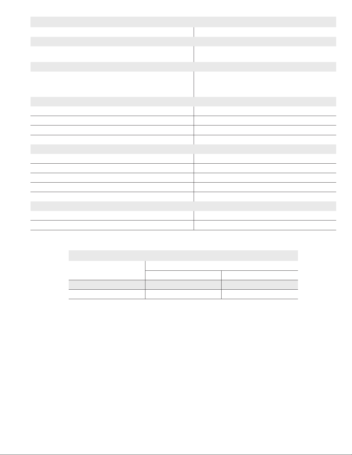
INSTALLATION CLEARANCES - INCHES (MM)
NOTES
One of the three sides must be 36 in. (914 mm).
One of the two remaining sides may be 12 in. (305 mm).
The remaining side may be 6 in. (152 mm).
Service Clearance − 30 in. (762 mm).
48 in. (1219 mm) clearance required on top of unit.
24 in. (610 mm) required between two units.
See
Notes
See
Notes
Service
See
Notes
See
Notes
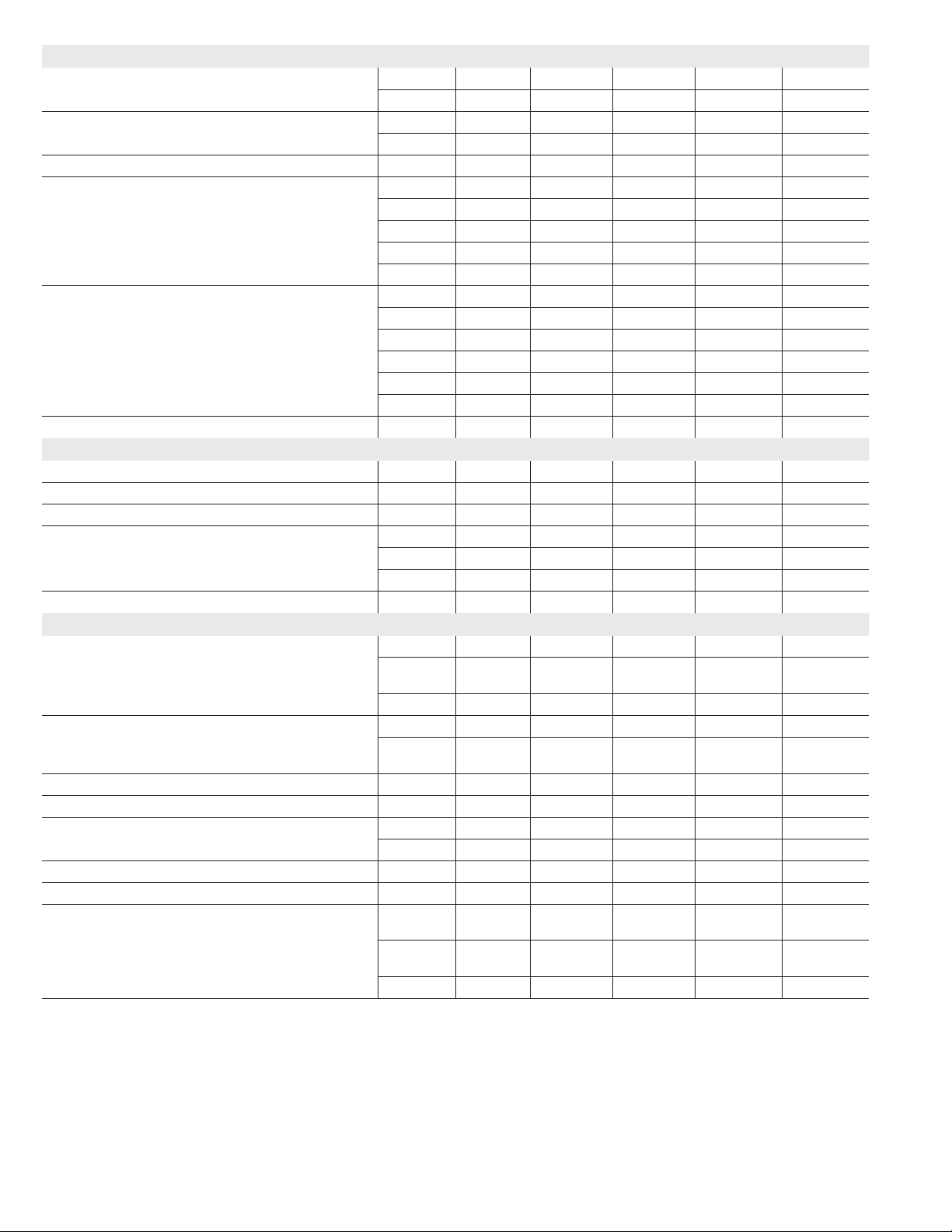
FIELD WIRING
A - Two Wire Power (not furnished)
B - Two Power (not furnished) See Electrical Data
C - Four Wire Low Voltage (not furnished) 18 ga. minimum
D - Six Wire Low Voltage (not furnished) 18 ga. minimum
All wiring must conform to NEC or CEC and local electrical codes.
DISCONNECT
SWITCH
(By Others)
LENNOX
AIR
CONDITIONER
B
THERMOSTAT
(Optional)
C
D
OUTDOOR SOUND DATA
1
Unit
Model No.
Octave Band Sound Power Levels dBA, re 10
Center Frequency - HZ
125 250 500 1000 2000 4000 8000
XC17-024 51.5 56.5 58.5 57.5 48.5 41.5 41.0 62
XC17-030 50.5 54.5 58.5 59.5 49.5 42.5 42.0 63
XC17-036 57.5 63.0 67.0 65.0 59.5 53.0 45.0 70
XC17-042 56.0 60.0 63.0 63.0 58.5 51.5 45.5 70
XC17-048 57.5 65.0 69.5 67.5 63.0 57.0 50.0 73
XC17-060 58.0 65.5 70.0 67.5 63.0 56.5 49.0 73
NOTE - the octave sound power data does not include tonal correction.
1
Tested according to AHRI Standard 270-2008 test conditions.
-12
Watts
DISCONNECT
SWITCH
(By Others)
A
LENNOX
HEATING UNIT
OR
AIR HANDLER
UNIT
1
Sound Rating
Number (dB)
XC17 - 2 to 5 Ton Air Conditioner / Page 11
Page 12
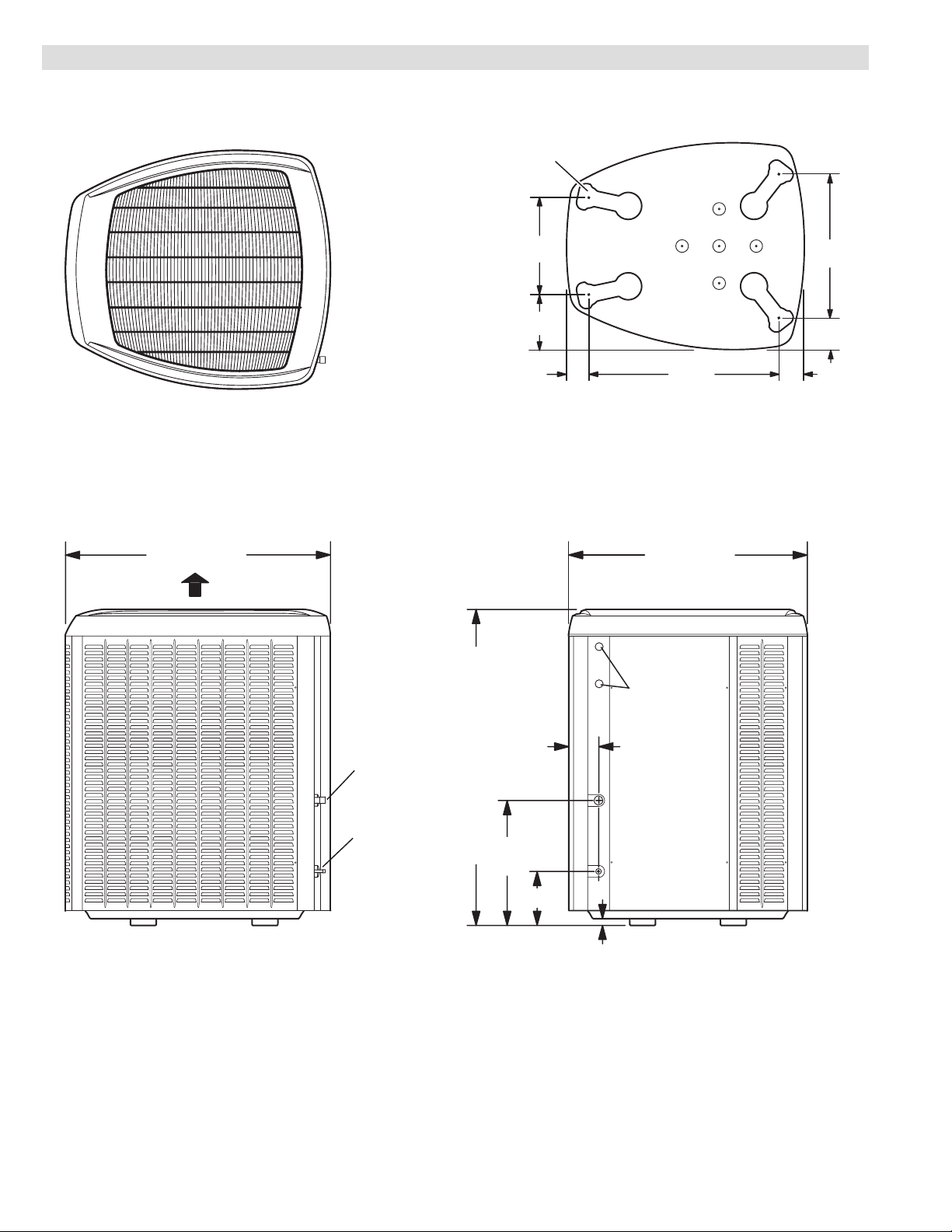
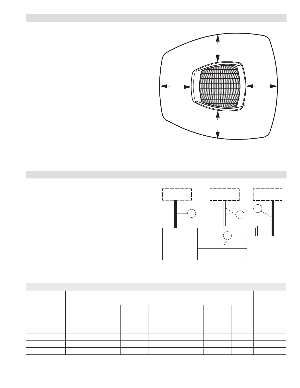
DIMENSIONS - INCHES (MM)
WEIV SSECCAWEIV EDIS
UNIT SUPPORT
FEET
TOP VIEW
39-1/2 (1003) 35-1/2 (902)
DISCHARGE
AIR
16-7/8
(429)
8-3/4
(222)
3-1/8
(79)
30-3/4
(781)
TOP VIEW BASE SECTION
26-7/8
(683)
3-3/4
(95)
4-5/8
(117)
SUCTION LINE
INLET
LIQUID LINE
INLET
ELECTRICAL
4-1/2
(114)
18-1/2
41 (1041) -024
47 (1140) -030-036-042-048-060
(470)
8 (203)
1 (25)
INLETS
XC17 - 2 to 5 Ton Air Conditioner / Page 12
Page 13
TXV USAGE
Model No. Order No.
XC17-024 37L51
XC17-030 37L51
XC17-036 39L72
XC17-042 39L72
XC17-048 91M02
XC17-060 91M02
CX34 upow coils and all Lennox air handlers (except CB26UH “R”) are
shipped with a factory installed TXV. In most cases, no change out of the valve
is needed.
If a change out is required it will be listed in the “TXV SUBSTITUTIONS” table.
The correct TXV must be ordered and eld installed. C33 coils and all horizontal and downow coils are shipped without a TXV. The TXV must be ordered
and eld installed.
MOST POPULAR MATCHES
Outdoor Unit
Model No.
XC17-024
XC17-030 CX34-31
XC17-036 CX34-38
XC17-042 CX34-50/60C
XC17-048 CX34-50/60C
XC17-060 CX34-62D
Indoor Unit
Model No
CX34-31
*tXV SUBSTITUTIONS
Indoor Coils/Air Handlers with factory installed expansion
valves that require eld replacement
Model No.
XC17-030 CBX32M-042 37L51
XC17-030 CBX32M-048 37L51
XC17-030 CX34-42 37L51
XC17-030 CX34-43 37L51
XC17-030 CX34-44/48 37L51
XC17-036 C33-44 39L72
XC17-036 CBX27UH-036 39L72
XC17-036 CBX32M-030 39L72
XC17-036 CBX32M-036 39L72
XC17-036 CBX32MV-024/030 39L72
XC17-036 CBX32MV-036 39L72
XC17-036 CBX40UHV-030 39L72
XC17-036 CBX40UHV-036 39L72
XC17-036 CX34-36 39L72
XC17-036 CX34-38 39L72
XC17-036 CX34-49 39L72
XC17-036 CX34-50/60 39L72
XC17-036 CX34-62 39L72
XC17-042 C33-44 39L72
XC17-042 C33-48 39L72
XC17-042 CBX27UH-048 39L72
XC17-042 CBX32M-036 39L72
XC17-042 CBX32M-048 39L72
XC17-042 CBX32MV-036 39L72
XC17-042 CBX40UHV-036 39L72
XC17-042 CX34-38 39L72
XC17-042 CX34-49 39L72
XC17-042 CX34-50/60 39L72
XC17-042 CX34-62 39L72
XC17-048 CBX32MV-036 91M02
XC17-048 CBX40UHV-036 91M02
XC17-048 CX34-44/48 91M02
XC17-060 CX34-44/48 91M02
* Factory installed expansion valve on the indoor coil or air handler shown
must be replaced with the expansion valve listed (ordered separately).
Indoor Coil or
Air Handler
Order No.
XC17 - 2 to 5 Ton Air Conditioner / Page 13
Page 14

AHRI SYSTEM MATCHES
NOTE - For the latest up-to-date system matches please visit the AHRI web site at http://www.ahridirectory.org
Model
No.
XC17-024-230 TXV 22,600 15.70 13.20 C33-19 G61MPV-36B-045 3844057
XC17-024-230 TXV 22,600 15.70 13.20 C33-19 G61MPV-36B-070 3844058
XC17-024-230 TXV 22,600 16.00 13.50 C33-19 G61MPV-36C-090 3844059
XC17-024-230 TXV 23,600 17.00 14.00 C33-19 SL280UH070V36A 4029656
XC17-024-230 TXV 23,600 17.00 14.00 C33-19 SL280UH070XV36A 4037938
XC17-024-230 TXV 22,000 14.00 11.70 C33-19 3843999
XC17-024-230 TXV 22,600 16.00 13.20 C33-24 SL280UH070V36A 4029673
XC17-024-230 TXV 22,600 16.00 13.20 C33-24 SL280UH070XV36A 4037944
XC17-024-230 TXV 22,400 16.00 13.50 C33-24 SL280UH090V36B 4029674
XC17-024-230 TXV 22,600 16.20 13.50 C33-24 SLP98UH070V36B 4035336
XC17-024-230 TXV 22,600 16.20 13.50 C33-24 SLP98UH090V36C 4035337
XC17-024-230 TXV 23,000 14.70 12.20 C33-24 3844000
XC17-024-230 TXV 23,800 17.00 14.00 C33-25 CBWMV-36B-070 4208021
XC17-024-230 TXV 24,200 17.00 14.20 C33-25 G61MPV-36B-045 3844064
XC17-024-230 TXV 24,000 17.20 14.20 C33-25 G61MPV-36B-070 3844065
XC17-024-230 TXV 24,200 17.00 14.20 C33-25 G61MPV-36B-071 3844066
XC17-024-230 TXV 23,600 16.00 13.20 C33-25 O23V2/3-70/90 3844125
XC17-024-230 TXV 24,000 17.00 14.20 C33-25 SL280UH070V36A 4029657
XC17-024-230 TXV 24,000 17.00 14.20 C33-25 SL280UH070XV36A 4037939
XC17-024-230 TXV 24,400 17.50 14.50 C33-25 SL280UH090V36B 4029658
XC17-024-230 TXV 24,000 17.20 14.50 C33-25 SLP98UH070V36B 4035338
XC17-024-230 TXV 23,400 15.00 12.50 C33-25 3844001
XC17-024-230 TXV 23,200 16.20 13.50 C33-30 G61MPV-36B-045 3844070
XC17-024-230 TXV 23,200 16.20 13.50 C33-30 G61MPV-36B-070 3844071
XC17-024-230 TXV 23,200 16.20 13.50 C33-30 G61MPV-36B-071 3844072
XC17-024-230 TXV 23,000 16.50 13.70 C33-30 G61MPV-36C-090 3844073
XC17-024-230 TXV 23,200 16.50 13.70 C33-30 SL280UH070V36A 4029659
XC17-024-230 TXV 23,200 16.50 13.70 C33-30 SL280UH070XV36A 4037940
XC17-024-230 TXV 23,000 16.50 13.70 C33-30 SL280UH090V36B 4029660
XC17-024-230 TXV 23,200 16.50 13.70 C33-30 SLP98UH070V36B 4035339
XC17-024-230 TXV 23,000 16.50 13.70 C33-30 SLP98UH090V36C 4035340
XC17-024-230 TXV 22,600 14.50 12.20 C33-30 3844002
XC17-024-230 TXV 24,400 17.20 14.20 C33-31 G61MPV-36B-045 3844078
XC17-024-230 TXV 24,400 17.50 14.50 C33-31 G61MPV-36B-070 3844079
XC17-024-230 TXV 24,600 17.20 14.50 C33-31 G61MPV-36B-071 3844080
XC17-024-230 TXV 24,200 16.50 13.70 C33-31 O23V2/3-70/90 3844126
XC17-024-230 TXV 24,400 17.50 14.50 C33-31 SL280UH070V36A 4029661
XC17-024-230 TXV 24,400 17.50 14.50 C33-31 SL280UH070XV36A 4037941
XC17-024-230 TXV 24,800 17.70 14.70 C33-31 SL280UH090V36B 4029662
XC17-024-230 TXV 24,400 17.70 14.50 C33-31 SLP98UH070V36B 4035341
XC17-024-230 TXV 23,800 15.20 12.70 C33-31 3844003
XC17-024-230 TXV 23,600 16.20 13.50 C33-36 O23V2/3-70/90 3844127
NOTES:
TXV = Matched with Thermostatic Expansion Valve.
RFC = Matched with RFC metering device.
Ratings are certied in accordance with USE certication program which is based on AHRI Standard 210/240; 95°F outdoor air temperature, 80°F db / 67°F wb entering
evaporator air with 25 ft. of connecting refrigerant lines.
All ratings include the use of a blower time delay relay (TDR). All Lennox variable-speed furnaces and Air Handlers have time delay capabilities. Other Furnaces and Air
Handlers may require an optional time delay relay (58M81) for eld installation. See furnace or air handler specications to determine if relay is needed.
Also see Expansion Valve Kit Usage Table.
Expansion
Device
Capacity SEER EER
Coil or
Air Handler
Furnace
AHRI
Reference
XC17 - 2 to 5 Ton Air Conditioner / Page 14
Page 15

AHRI SYSTEM MATCHES
NOTE - For the latest up-to-date system matches please visit the AHRI web site at http://www.ahridirectory.org
Model
No.
XC17-024-230 TXV 24,000 17.20 14.20 C33-36 SL280UH070V36A 4029663
XC17-024-230 TXV 24,000 17.20 14.20 C33-36 SL280UH070XV36A 4037942
XC17-024-230 TXV 24,200 17.20 14.20 C33-36 SL280UH090V36B 4029664
XC17-024-230 TXV 23,400 15.00 12.50 C33-36 3844004
XC17-024-230 TXV 24,800 17.50 14.50 C33-38 G61MPV-36B-045 3844086
XC17-024-230 TXV 24,600 17.50 14.50 C33-38 G61MPV-36B-070 3844087
XC17-024-230 TXV 24,800 17.50 14.50 C33-38 G61MPV-36B-071 3844088
XC17-024-230 TXV 24,400 16.70 14.00 C33-38 O23V2/3-70/90 3844128
XC17-024-230 TXV 24,600 17.70 14.70 C33-38 SL280UH070V36A 4029665
XC17-024-230 TXV 24,600 17.70 14.70 C33-38 SL280UH070XV36A 4037943
XC17-024-230 TXV 25,000 18.00 14.70 C33-38 SL280UH090V36B 4029666
XC17-024-230 TXV 24,600 17.70 14.70 C33-38 SLP98UH070V36B 4035342
XC17-024-230 TXV 24,000 15.20 12.70 C33-38 3844005
XC17-024-230 TXV 24,200 17.50 14.50 CBX27UH-024 3844131
XC17-024-230 TXV 24,400 17.70 14.70 CBX27UH-030 3844132
XC17-024-230 TXV 23,400 15.00 12.70 CBX32M-018/024 3844129
XC17-024-230 TXV 23,800 15.70 13.20 CBX32M-030 3844130
XC17-024-230 TXV 23,800 16.50 13.70 CBX32MV-018/024 3844133
XC17-024-230 TXV 24,200 17.20 14.20 CBX32MV-024/030 3844134
XC17-024-230 TXV 24,800 17.50 14.50 CBX32MV-036 3844135
XC17-024-230 TXV 24,400 17.50 14.50 CBX40UHV-024 3844136
XC17-024-230 TXV 24,400 17.70 14.50 CBX40UHV-030 3844137
XC17-024-230 TXV 24,800 17.70 14.70 CBX40UHV-036 3844138
XC17-024-230 TXV 21,800 14.00 11.70 CH23-21 3844008
XC17-024-230 TXV 22,400 16.20 13.50 CH23-31 SL280UH090V48B 4249280
XC17-024-230 TXV 22,000 14.00 11.70 CH23-31 3844009
XC17-024-230 TXV 23,600 16.70 14.00 CH23-41 SL280UH090V48B 4249281
XC17-024-230 TXV 23,400 15.00 12.50 CH23-41 3844010
XC17-024-230 TXV 23,400 17.00 14.00 CH33-19 SL280UH070V36A 3946672
XC17-024-230 TXV 23,400 17.00 14.00 CH33-19 SL280UH070XV36A 4037933
XC17-024-230 TXV 23,000 14.70 12.50 CH33-19 3844011
XC17-024-230 TXV 23,400 16.50 13.70 CH33-24/30 SL280UH070V36A 3946673
XC17-024-230 TXV 23,400 16.50 13.70 CH33-24/30 SL280UH070XV36A 4037934
XC17-024-230 TXV 22,800 14.50 12.20 CH33-24/30 3844012
XC17-024-230 TXV 23,800 17.00 14.00 CH33-25 SL280UH090V48B 4249294
XC17-024-230 TXV 24,000 17.20 14.20 CH33-25 SLP98UH070V36B 4020757
XC17-024-230 TXV 24,000 17.00 14.20 CH33-25A SL280UH070V36A 3946674
XC17-024-230 TXV 24,000 17.00 14.20 CH33-25A SL280UH070XV36A 4037935
XC17-024-230 TXV 23,600 15.00 12.70 CH33-25A 3844013
XC17-024-230 TXV 24,000 17.00 14.20 CH33-25B G61MPV-36B-045 3844103
XC17-024-230 TXV 24,000 17.20 14.20 CH33-25B G61MPV-36B-070 3844104
XC17-024-230 TXV 24,000 17.00 14.00 CH33-25B G61MPV-36B-071 3844105
NOTES:
TXV = Matched with Thermostatic Expansion Valve.
RFC = Matched with RFC metering device.
Ratings are certied in accordance with USE certication program which is based on AHRI Standard 210/240; 95°F outdoor air temperature, 80°F db / 67°F wb entering
evaporator air with 25 ft. of connecting refrigerant lines.
All ratings include the use of a blower time delay relay (TDR). All Lennox variable-speed furnaces and Air Handlers have time delay capabilities. Other Furnaces and Air
Handlers may require an optional time delay relay (58M81) for eld installation. See furnace or air handler specications to determine if relay is needed.
Also see Expansion Valve Kit Usage Table.
Expansion
Device
Capacity SEER EER
Coil or
Air Handler
Furnace
AHRI
Reference
XC17 - 2 to 5 Ton Air Conditioner / Page 15
Page 16
AHRI SYSTEM MATCHES
NOTE - For the latest up-to-date system matches please visit the AHRI web site at http://www.ahridirectory.org
Model
No.
XC17-024-230 TXV 24,200 17.50 14.50 CH33-25B SL280UH090V36B 3946675
XC17-024-230 TXV 23,400 15.00 12.50 CH33-25B 3844014
XC17-024-230 TXV 24,400 17.20 14.50 CH33-31 SL280UH090V48B 4249295
XC17-024-230 TXV 24,600 17.70 14.70 CH33-31 SLP98UH070V36B 4020758
XC17-024-230 TXV 24,600 17.50 14.50 CH33-31A SL280UH070V36A 3946676
XC17-024-230 TXV 24,600 17.50 14.50 CH33-31A SL280UH070XV36A 4037936
XC17-024-230 TXV 24,000 15.20 13.00 CH33-31A 3844015
XC17-024-230 TXV 24,600 17.50 14.50 CH33-31B G61MPV-36B-045 3844109
XC17-024-230 TXV 24,600 17.50 14.50 CH33-31B G61MPV-36B-070 3844110
XC17-024-230 TXV 24,800 17.50 14.50 CH33-31B G61MPV-36B-071 3844111
XC17-024-230 TXV 25,000 17.70 14.70 CH33-31B SL280UH090V36B 3946677
XC17-024-230 TXV 24,000 15.20 12.70 CH33-31B 3844016
XC17-024-230 TXV 23,800 17.20 14.20 CH33-36 SLP98UH070V36B 4020759
XC17-024-230 TXV 24,000 17.50 14.50 CH33-36 SLP98UH090V36C 4020760
XC17-024-230 TXV 23,800 17.00 14.00 CH33-36A SL280UH070V36A 3946678
XC17-024-230 TXV 23,800 17.00 14.00 CH33-36A SL280UH070XV36A 4037937
XC17-024-230 TXV 23,400 15.00 12.50 CH33-36A 3844017
XC17-024-230 TXV 23,600 16.70 14.00 CH33-36B SL280UH090V48B 4249282
XC17-024-230 TXV 24,000 17.00 14.20 CH33-36B G61MPV-36B-045 3844115
XC17-024-230 TXV 24,000 17.00 14.20 CH33-36B G61MPV-36B-070 3844116
XC17-024-230 TXV 24,000 17.00 14.00 CH33-36B G61MPV-36B-071 3844117
XC17-024-230 TXV 24,200 17.20 14.50 CH33-36B SL280UH090V36B 3946679
XC17-024-230 TXV 23,400 15.00 12.50 CH33-36B 3844018
XC17-024-230 TXV 24,000 17.50 14.50 CH33-36C G61MPV-36C-090 3844118
XC17-024-230 TXV 23,600 15.00 12.70 CH33-36C 3844019
XC17-024-230 TXV 22,800 15.70 13.20 CR33-24 G61MPV-36B-045 3844090
XC17-024-230 TXV 22,600 16.00 13.20 CR33-24 G61MPV-36B-070 3844091
XC17-024-230 TXV 22,400 16.20 13.20 CR33-24 SLP98DF070V36B 4185202
XC17-024-230 TXV 22,200 14.20 12.00 CR33-24 3844006
XC17-024-230 TXV 24,400 17.20 14.20 CR33-30/36 G61MPV-36B-045 3844095
XC17-024-230 TXV 24,200 17.20 14.20 CR33-30/36 G61MPV-36B-070 3844096
XC17-024-230 TXV 24,400 17.20 14.20 CR33-30/36 G61MPV-36B-071 3844097
XC17-024-230 TXV 24,600 17.20 14.20 CR33-30/36 SL280DF070V36A 3946671
XC17-024-230 TXV 24,000 17.50 14.50 CR33-30/36 SLP98DF070V36B 4185203
XC17-024-230 TXV 24,000 17.50 14.50 CR33-30/36 SLP98DF090V36C 4185204
XC17-024-230 TXV 23,600 15.20 12.70 CR33-30/36 3844007
XC17-024-230 TXV 22,600 15.70 13.20 CX34-18/24 G61MPV-36B-045 3844022
XC17-024-230 TXV 22,600 15.70 13.20 CX34-18/24 G61MPV-36B-070 3844023
XC17-024-230 TXV 22,600 16.00 13.50 CX34-18/24 G61MPV-36C-090 3844024
XC17-024-230 TXV 22,600 16.00 13.20 CX34-18/24 SL280UH070V36A 3946658
XC17-024-230 TXV 22,600 16.00 13.20 CX34-18/24 SL280UH070XV36A 4037926
XC17-024-230 TXV 22,400 16.00 13.50 CX34-18/24 SL280UH090V36B 3946659
NOTES:
TXV = Matched with Thermostatic Expansion Valve.
RFC = Matched with RFC metering device.
Ratings are certied in accordance with USE certication program which is based on AHRI Standard 210/240; 95°F outdoor air temperature, 80°F db / 67°F wb entering
evaporator air with 25 ft. of connecting refrigerant lines.
All ratings include the use of a blower time delay relay (TDR). All Lennox variable-speed furnaces and Air Handlers have time delay capabilities. Other Furnaces and Air
Handlers may require an optional time delay relay (58M81) for eld installation. See furnace or air handler specications to determine if relay is needed.
Also see Expansion Valve Kit Usage Table.
Expansion
Device
Capacity SEER EER
Coil or
Air Handler
Furnace
AHRI
Reference
XC17 - 2 to 5 Ton Air Conditioner / Page 16
Page 17

AHRI SYSTEM MATCHES
NOTE - For the latest up-to-date system matches please visit the AHRI web site at http://www.ahridirectory.org
Model
No.
XC17-024-230 TXV 22,600 16.20 13.50 CX34-18/24 SLP98UH070V36B 4020750
XC17-024-230 TXV 22,600 16.20 13.50 CX34-18/24 SLP98UH090V36C 4020751
XC17-024-230 TXV 22,000 14.00 11.70 CX34-18/24 3843992
XC17-024-230 TXV 23,600 17.00 14.00 CX34-19 SL280UH070V36A 3946660
XC17-024-230 TXV 23,600 17.00 14.00 CX34-19 SL280UH070XV36A 4037927
XC17-024-230 TXV 23,000 14.70 12.20 CX34-19 3843993
XC17-024-230 TXV 23,800 17.00 14.00 CX34-25 CBWMV-36B-070 4208022
XC17-024-230 TXV 24,200 17.00 14.20 CX34-25 G61MPV-36B-045 3844029
XC17-024-230 TXV 24,000 17.20 14.20 CX34-25 G61MPV-36B-070 3844030
XC17-024-230 TXV 24,200 17.00 14.20 CX34-25 G61MPV-36B-071 3844031
XC17-024-230 TXV 23,600 16.00 13.20 CX34-25 O23V2/3-70/90 3844121
XC17-024-230 TXV 24,000 17.00 14.20 CX34-25 SL280UH070V36A 3946661
XC17-024-230 TXV 24,000 17.00 14.20 CX34-25 SL280UH070XV36A 4037928
XC17-024-230 TXV 24,400 17.50 14.50 CX34-25 SL280UH090V36B 3946662
XC17-024-230 TXV 23,800 17.00 14.00 CX34-25 SL280UH090V48B 4249275
XC17-024-230 TXV 24,000 17.20 14.50 CX34-25 SLP98UH070V36B 4020752
XC17-024-230 TXV 23,400 15.00 12.50 CX34-25 3843994
XC17-024-230 TXV 23,200 16.20 13.50 CX34-30 G61MPV-36B-045 3844035
XC17-024-230 TXV 23,200 16.20 13.50 CX34-30 G61MPV-36B-070 3844036
XC17-024-230 TXV 23,200 16.20 13.50 CX34-30 G61MPV-36B-071 3844037
XC17-024-230 TXV 23,000 16.50 13.70 CX34-30 G61MPV-36C-090 3844038
XC17-024-230 TXV 23,200 16.50 13.70 CX34-30 SL280UH070V36A 3946663
XC17-024-230 TXV 23,200 16.50 13.70 CX34-30 SL280UH070XV36A 4037929
XC17-024-230 TXV 23,000 16.50 13.70 CX34-30 SL280UH090V36B 3946664
XC17-024-230 TXV 23,000 16.00 13.50 CX34-30 SL280UH090V48B 4249276
XC17-024-230 TXV 23,200 16.50 13.70 CX34-30 SLP98UH070V36B 4020753
XC17-024-230 TXV 23,000 16.50 13.70 CX34-30 SLP98UH090V36C 4020754
XC17-024-230 TXV 22,600 14.50 12.20 CX34-30 3843995
XC17-024-230 TXV 24,400 17.20 14.20 CX34-31 G61MPV-36B-045 3844043
XC17-024-230 TXV 24,400 17.50 14.50 CX34-31 G61MPV-36B-070 3844044
XC17-024-230 TXV 24,600 17.20 14.50 CX34-31 G61MPV-36B-071 3844045
XC17-024-230 TXV 24,200 16.50 13.70 CX34-31 O23V2/3-70/90 3844122
XC17-024-230 TXV 24,400 17.50 14.50 CX34-31 SL280UH070V36A 3946665
XC17-024-230 TXV 24,400 17.50 14.50 CX34-31 SL280UH070XV36A 4037930
XC17-024-230 TXV 24,800 17.70 14.70 CX34-31 SL280UH090V36B 3946666
XC17-024-230 TXV 24,200 17.20 14.20 CX34-31 SL280UH090V48B 4249277
XC17-024-230 TXV 24,400 17.70 14.50 CX34-31 SLP98UH070V36B 4020755
XC17-024-230 TXV 23,800 15.20 12.70 CX34-31 3843996
XC17-024-230 TXV 23,600 16.20 13.50 CX34-36 O23V2/3-70/90 3844123
XC17-024-230 TXV 24,000 17.20 14.20 CX34-36 SL280UH070V36A 3946667
XC17-024-230 TXV 24,000 17.20 14.20 CX34-36 SL280UH070XV36A 4037931
XC17-024-230 TXV 24,200 17.20 14.20 CX34-36 SL280UH090V36B 3946668
NOTES:
TXV = Matched with Thermostatic Expansion Valve.
RFC = Matched with RFC metering device.
Ratings are certied in accordance with USE certication program which is based on AHRI Standard 210/240; 95°F outdoor air temperature, 80°F db / 67°F wb entering
evaporator air with 25 ft. of connecting refrigerant lines.
All ratings include the use of a blower time delay relay (TDR). All Lennox variable-speed furnaces and Air Handlers have time delay capabilities. Other Furnaces and Air
Handlers may require an optional time delay relay (58M81) for eld installation. See furnace or air handler specications to determine if relay is needed.
Also see Expansion Valve Kit Usage Table.
Expansion
Device
Capacity SEER EER
Coil or
Air Handler
Furnace
AHRI
Reference
XC17 - 2 to 5 Ton Air Conditioner / Page 17
Page 18

AHRI SYSTEM MATCHES
NOTE - For the latest up-to-date system matches please visit the AHRI web site at http://www.ahridirectory.org
Model
No.
XC17-024-230 TXV 23,800 16.70 14.00 CX34-36 SL280UH090V48B 4249278
XC17-024-230 TXV 23,400 15.00 12.50 CX34-36 3843997
XC17-024-230 TXV 24,800 17.50 14.50 CX34-38 G61MPV-36B-045 3844051
XC17-024-230 TXV 24,600 17.50 14.50 CX34-38 G61MPV-36B-070 3844052
XC17-024-230 TXV 24,800 17.50 14.50 CX34-38 G61MPV-36B-071 3844053
XC17-024-230 TXV 24,400 16.70 14.00 CX34-38 O23V2/3-70/90 3844124
XC17-024-230 TXV 24,600 17.70 14.70 CX34-38 SL280UH070V36A 3946669
XC17-024-230 TXV 24,600 17.70 14.70 CX34-38 SL280UH070XV36A 4037932
XC17-024-230 TXV 25,000 18.00 14.70 CX34-38 SL280UH090V36B 3946670
XC17-024-230 TXV 24,400 17.20 14.50 CX34-38 SL280UH090V48B 4249279
XC17-024-230 TXV 24,600 17.70 14.70 CX34-38 SLP98UH070V36B 4020756
XC17-024-230 TXV 24,000 15.20 12.70 CX34-38 3843998
XC17-030-230 TXV 27,400 15.70 12.70 C33-25 G61MPV-36B-045 3844223
XC17-030-230 TXV 27,400 15.70 13.00 C33-25 G61MPV-36B-070 3844224
XC17-030-230 TXV 27,400 15.70 12.70 C33-25 G61MPV-36B-071 3844225
XC17-030-230 TXV 27,600 16.00 13.00 C33-25 SL280UH070V36A 4036738
XC17-030-230 TXV 27,600 16.00 13.00 C33-25 SL280UH070XV36A 4037955
XC17-030-230 TXV 27,800 16.20 13.50 C33-25 SL280UH090V36B 4036742
XC17-030-230 TXV 27,600 16.00 13.20 C33-25 SLP98UH070V36B 4035343
XC17-030-230 TXV 27,200 14.50 12.00 C33-25 3844147
XC17-030-230 TXV 27,000 15.20 12.70 C33-30 G61MPV-36B-045 3844229
XC17-030-230 TXV 26,800 15.50 12.70 C33-30 G61MPV-36B-070 3844230
XC17-030-230 TXV 26,800 15.50 12.70 C33-30 G61MPV-36B-071 3844231
XC17-030-230 TXV 27,200 15.70 13.00 C33-30 SL280UH070V36A 4036746
XC17-030-230 TXV 27,200 15.70 13.00 C33-30 SL280UH070XV36A 4037958
XC17-030-230 TXV 26,800 15.70 13.00 C33-30 SL280UH090V36B 4036750
XC17-030-230 TXV 27,000 15.70 13.00 C33-30 SLP98UH070V36B 4035344
XC17-030-230 TXV 26,800 14.00 11.70 C33-30 3844148
XC17-030-230 TXV 28,200 16.20 13.20 C33-31 G61MPV-36B-045 3844235
XC17-030-230 TXV 28,200 16.50 13.50 C33-31 G61MPV-36B-070 3844236
XC17-030-230 TXV 28,200 16.20 13.50 C33-31 G61MPV-36B-071 3844237
XC17-030-230 TXV 28,400 16.70 13.70 C33-31 SL280UH070V36A 4036754
XC17-030-230 TXV 28,400 16.70 13.70 C33-31 SL280UH070XV36A 4037959
XC17-030-230 TXV 28,400 17.00 13.70 C33-31 SL280UH090V36B 4036759
XC17-030-230 TXV 28,200 16.70 13.70 C33-31 SLP98UH070V36B 4035345
XC17-030-230 TXV 27,800 15.00 12.20 C33-31 3844149
XC17-030-230 TXV 27,600 16.00 13.00 C33-36 G61MPV-36B-045 3844241
XC17-030-230 TXV 27,400 16.00 13.00 C33-36 G61MPV-36B-070 3844242
XC17-030-230 TXV 27,400 16.00 13.00 C33-36 G61MPV-36B-071 3844243
XC17-030-230 TXV 27,800 16.20 13.20 C33-36 G61MPV-36C-090 3844244
XC17-030-230 TXV 27,600 16.20 13.20 C33-36 SL280UH070V36A 4036763
XC17-030-230 TXV 27,600 16.20 13.20 C33-36 SL280UH070XV36A 4037956
NOTES:
TXV = Matched with Thermostatic Expansion Valve.
RFC = Matched with RFC metering device.
Ratings are certied in accordance with USE certication program which is based on AHRI Standard 210/240; 95°F outdoor air temperature, 80°F db / 67°F wb entering
evaporator air with 25 ft. of connecting refrigerant lines.
All ratings include the use of a blower time delay relay (TDR). All Lennox variable-speed furnaces and Air Handlers have time delay capabilities. Other Furnaces and Air
Handlers may require an optional time delay relay (58M81) for eld installation. See furnace or air handler specications to determine if relay is needed.
Also see Expansion Valve Kit Usage Table.
Expansion
Device
Capacity SEER EER
Coil or
Air Handler
Furnace
AHRI
Reference
XC17 - 2 to 5 Ton Air Conditioner / Page 18
Page 19

AHRI SYSTEM MATCHES
NOTE - For the latest up-to-date system matches please visit the AHRI web site at http://www.ahridirectory.org
Model
No.
XC17-030-230 TXV 27,800 16.50 13.50 C33-36 SL280UH090V36B 4036767
XC17-030-230 TXV 27,600 16.20 13.20 C33-36 SLP98UH070V36B 4035346
XC17-030-230 TXV 28,000 16.50 13.50 C33-36 SLP98UH090V36C 4035347
XC17-030-230 TXV 27,200 14.50 12.00 C33-36 3844150
XC17-030-230 TXV 28,400 16.50 13.50 C33-38 G61MPV-36B-045 3844249
XC17-030-230 TXV 28,200 16.50 13.50 C33-38 G61MPV-36B-070 3844250
XC17-030-230 TXV 28,200 16.50 13.50 C33-38 G61MPV-36B-071 3844251
XC17-030-230 TXV 28,600 16.70 13.70 C33-38 SL280UH070V36A 4036772
XC17-030-230 TXV 28,600 16.70 13.70 C33-38 SL280UH070XV36A 4037957
XC17-030-230 TXV 28,600 17.00 14.00 C33-38 SL280UH090V36B 4036777
XC17-030-230 TXV 28,400 16.70 13.70 C33-38 SLP98UH070V36B 4035348
XC17-030-230 TXV 28,000 15.00 12.50 C33-38 3844151
XC17-030-230 TXV 27,600 16.00 13.00 C33-42 G61MPV-36B-045 3844254
XC17-030-230 TXV 27,400 16.00 13.00 C33-42 G61MPV-36B-070 3844255
XC17-030-230 TXV 27,400 16.00 13.00 C33-42 G61MPV-36B-071 3844256
XC17-030-230 TXV 27,800 16.50 13.50 C33-42 SL280UH090V36B 4036781
XC17-030-230 TXV 27,600 16.20 13.20 C33-42 SLP98UH070V36B 4035349
XC17-030-230 TXV 27,200 14.50 12.00 C33-42 3844152
XC17-030-230 TXV 28,200 16.50 13.50 C33-43 G61MPV-36B-045 3844259
XC17-030-230 TXV 28,200 16.50 13.50 C33-43 G61MPV-36B-070 3844260
XC17-030-230 TXV 28,200 16.50 13.50 C33-43 G61MPV-36B-071 3844261
XC17-030-230 TXV 28,600 17.00 14.00 C33-43 G61MPV-36C-090 3844262
XC17-030-230 TXV 28,400 16.20 13.50 C33-43 O23V3/4-105/120 3844333
XC17-030-230 TXV 28,600 17.00 14.00 C33-43 SL280UH090V36B 4036786
XC17-030-230 TXV 28,400 16.70 13.70 C33-43 SLP98UH070V36B 4035350
XC17-030-230 TXV 28,800 17.20 14.00 C33-43 SLP98UH090V36C 4035351
XC17-030-230 TXV 28,000 15.00 12.50 C33-43 3844153
XC17-030-230 TXV 28,000 16.20 13.20 C33-48 G61MPV-36B-045 3844266
XC17-030-230 TXV 28,000 16.20 13.20 C33-48 G61MPV-36B-070 3844267
XC17-030-230 TXV 28,000 16.20 13.20 C33-48 G61MPV-36B-071 3844268
XC17-030-230 TXV 28,400 16.70 13.70 C33-48 G61MPV-36C-090 3844269
XC17-030-230 TXV 28,400 17.00 13.70 C33-48 SL280UH090V36B 4036790
XC17-030-230 TXV 28,200 16.70 13.70 C33-48 SLP98UH070V36B 4035352
XC17-030-230 TXV 28,600 16.70 13.70 C33-48 SLP98UH090V36C 4035353
XC17-030-230 TXV 27,800 15.00 12.20 C33-48 3844154
XC17-030-230 TXV 28,200 16.70 13.50 CBX27UH-030 3844336
XC17-030-230 TXV 28,200 17.00 13.70 CBX27UH-036 3844337
XC17-030-230 TXV 27,800 15.70 12.70 CBX32M-030 3844334
XC17-030-230 TXV 27,800 15.20 12.70 CBX32M-036 3844335
XC17-030-230 TXV 28,000 16.70 13.50 CBX32MV-024/030 3844338
XC17-030-230 TXV 28,200 17.00 13.70 CBX32MV-036 3844339
XC17-030-230 TXV 28,000 17.50 14.20 CBX40UHV-030 3844340
NOTES:
TXV = Matched with Thermostatic Expansion Valve.
RFC = Matched with RFC metering device.
Ratings are certied in accordance with USE certication program which is based on AHRI Standard 210/240; 95°F outdoor air temperature, 80°F db / 67°F wb entering
evaporator air with 25 ft. of connecting refrigerant lines.
All ratings include the use of a blower time delay relay (TDR). All Lennox variable-speed furnaces and Air Handlers have time delay capabilities. Other Furnaces and Air
Handlers may require an optional time delay relay (58M81) for eld installation. See furnace or air handler specications to determine if relay is needed.
Also see Expansion Valve Kit Usage Table.
Expansion
Device
Capacity SEER EER
Coil or
Air Handler
Furnace
AHRI
Reference
XC17 - 2 to 5 Ton Air Conditioner / Page 19
Page 20

AHRI SYSTEM MATCHES
NOTE - For the latest up-to-date system matches please visit the AHRI web site at http://www.ahridirectory.org
Model
No.
XC17-030-230 TXV 28,400 17.00 14.00 CBX40UHV-036 3844341
XC17-030-230 TXV 26,200 15.20 12.50 CH23-31 G61MPV-36B-045 3844282
XC17-030-230 TXV 26,000 15.20 12.50 CH23-31 G61MPV-36B-070 3844283
XC17-030-230 TXV 26,000 15.20 12.50 CH23-31 G61MPV-36B-071 3844284
XC17-030-230 TXV 26,200 15.50 12.70 CH23-31 SLP98UH070V36B 4020772
XC17-030-230 TXV 27,600 16.00 13.20 CH23-41 G61MPV-36B-045 3844288
XC17-030-230 TXV 27,600 16.20 13.20 CH23-41 G61MPV-36B-070 3844289
XC17-030-230 TXV 27,600 16.20 13.20 CH23-41 G61MPV-36B-071 3844290
XC17-030-230 TXV 27,800 16.50 13.50 CH23-41 SL280UH070V36A 3946856
XC17-030-230 TXV 27,800 16.50 13.50 CH23-41 SL280UH070XV36A 4037950
XC17-030-230 TXV 28,000 16.70 13.70 CH23-41 SL280UH090V36B 3946857
XC17-030-230 TXV 28,000 16.70 13.70 CH23-41 SL280UH090V48B 4249290
XC17-030-230 TXV 27,800 16.50 13.50 CH23-41 SLP98UH070V36B 4020773
XC17-030-230 TXV 27,400 14.50 12.00 CH23-41 3844157
XC17-030-230 TXV 27,800 16.20 13.20 CH23-51 G61MPV-36B-045 3844294
XC17-030-230 TXV 27,800 16.50 13.50 CH23-51 G61MPV-36B-070 3844295
XC17-030-230 TXV 27,800 16.20 13.50 CH23-51 G61MPV-36B-071 3844296
XC17-030-230 TXV 28,000 16.70 13.50 CH23-51 G61MPV-36C-090 3844297
XC17-030-230 TXV 28,000 16.70 13.50 CH23-51 SL280UH070V36A 3946858
XC17-030-230 TXV 28,000 16.70 13.50 CH23-51 SL280UH070XV36A 4037952
XC17-030-230 TXV 28,200 17.00 13.70 CH23-51 SL280UH090V36B 3946859
XC17-030-230 TXV 28,200 16.70 13.70 CH23-51 SL280UH090V48B 4249291
XC17-030-230 TXV 27,800 16.70 13.50 CH23-51 SLP98UH070V36B 4020774
XC17-030-230 TXV 28,200 17.00 13.70 CH23-51 SLP98UH090V36C 4020775
XC17-030-230 TXV 27,400 14.70 12.00 CH23-51 3844158
XC17-030-230 TXV 28,000 16.50 13.50 CH33-25 SL280UH090V48B 4249296
XC17-030-230 TXV 27,600 16.20 13.20 CH33-25 SLP98UH070V36B 4020776
XC17-030-230 TXV 27,800 16.20 13.20 CH33-25A SL280UH070V36A 3946860
XC17-030-230 TXV 27,800 16.20 13.20 CH33-25A SL280UH070XV36A 4037953
XC17-030-230 TXV 27,400 14.70 12.00 CH33-25A 3844159
XC17-030-230 TXV 27,600 16.00 13.00 CH33-25B G61MPV-36B-045 3844302
XC17-030-230 TXV 27,600 16.00 13.20 CH33-25B G61MPV-36B-070 3844303
XC17-030-230 TXV 27,600 16.00 13.20 CH33-25B G61MPV-36B-071 3844304
XC17-030-230 TXV 27,800 16.50 13.50 CH33-25B SL280UH090V36B 3946861
XC17-030-230 TXV 27,400 14.50 12.00 CH33-25B 3844160
XC17-030-230 TXV 28,800 17.00 14.00 CH33-31 SL280UH090V48B 4249297
XC17-030-230 TXV 28,400 16.70 13.70 CH33-31 SLP98UH070V36B 4020777
XC17-030-230 TXV 28,400 16.50 13.50 CH33-31A SL280UH070V36A 3946862
XC17-030-230 TXV 28,400 16.50 13.50 CH33-31A SL280UH070XV36A 4037954
XC17-030-230 TXV 28,000 15.00 12.20 CH33-31A 3844161
XC17-030-230 TXV 28,400 16.50 13.50 CH33-31B G61MPV-36B-045 3844308
XC17-030-230 TXV 28,200 16.50 13.50 CH33-31B G61MPV-36B-070 3844309
NOTES:
TXV = Matched with Thermostatic Expansion Valve.
RFC = Matched with RFC metering device.
Ratings are certied in accordance with USE certication program which is based on AHRI Standard 210/240; 95°F outdoor air temperature, 80°F db / 67°F wb entering
evaporator air with 25 ft. of connecting refrigerant lines.
All ratings include the use of a blower time delay relay (TDR). All Lennox variable-speed furnaces and Air Handlers have time delay capabilities. Other Furnaces and Air
Handlers may require an optional time delay relay (58M81) for eld installation. See furnace or air handler specications to determine if relay is needed.
Also see Expansion Valve Kit Usage Table.
Expansion
Device
Capacity SEER EER
Coil or
Air Handler
Furnace
AHRI
Reference
XC17 - 2 to 5 Ton Air Conditioner / Page 20
Page 21

AHRI SYSTEM MATCHES
NOTE - For the latest up-to-date system matches please visit the AHRI web site at http://www.ahridirectory.org
Model
No.
XC17-030-230 TXV 28,200 16.50 13.50 CH33-31B G61MPV-36B-071 3844310
XC17-030-230 TXV 28,600 17.00 14.00 CH33-31B SL280UH090V36B 3946863
XC17-030-230 TXV 28,000 15.00 12.20 CH33-31B 3844162
XC17-030-230 TXV 27,600 16.20 13.20 CH33-36 SLP98UH070V36B 4020778
XC17-030-230 TXV 28,200 16.70 13.50 CH33-36 SLP98UH090V36C 4020779
XC17-030-230 TXV 27,600 16.00 13.00 CH33-36A SL280UH070V36A 3946864
XC17-030-230 TXV 27,600 16.00 13.00 CH33-36A SL280UH070XV36A 4037951
XC17-030-230 TXV 27,200 14.50 12.00 CH33-36A 3844163
XC17-030-230 TXV 27,800 16.50 13.50 CH33-36B SL280UH090V48B 4249292
XC17-030-230 TXV 27,600 16.00 13.00 CH33-36B G61MPV-36B-045 3844314
XC17-030-230 TXV 27,400 16.00 13.00 CH33-36B G61MPV-36B-070 3844315
XC17-030-230 TXV 27,400 16.00 13.00 CH33-36B G61MPV-36B-071 3844316
XC17-030-230 TXV 27,800 16.50 13.50 CH33-36B SL280UH090V36B 3946865
XC17-030-230 TXV 27,800 16.50 13.50 CH33-36B SL280UH090V48B 4249298
XC17-030-230 TXV 27,200 14.50 12.00 CH33-36B 3844164
XC17-030-230 TXV 28,000 16.50 13.50 CH33-36C G61MPV-36C-090 3844317
XC17-030-230 TXV 27,600 14.70 12.20 CH33-36C 3844165
XC17-030-230 TXV 28,400 16.70 13.70 CH33-42 SL280UH090V48B 4249293
XC17-030-230 TXV 28,200 16.20 13.20 CH33-42 G61MPV-36B-045 3844321
XC17-030-230 TXV 28,000 16.20 13.20 CH33-42 G61MPV-36B-070 3844322
XC17-030-230 TXV 28,000 16.20 13.20 CH33-42 G61MPV-36B-071 3844323
XC17-030-230 TXV 28,400 17.00 13.70 CH33-42 SL280UH090V36B 3946866
XC17-030-230 TXV 28,400 16.70 13.70 CH33-42 SL280UH090V48B 4249299
XC17-030-230 TXV 28,200 16.70 13.50 CH33-42 SLP98UH070V36B 4020780
XC17-030-230 TXV 27,800 15.00 12.20 CH33-42 3844166
XC17-030-230 TXV 29,200 17.20 14.00 CH33-43 SL280UH090V48B 4249300
XC17-030-230 TXV 29,000 17.20 14.00 CH33-43 SLP98UH070V36B 4020781
XC17-030-230 TXV 29,000 17.50 14.20 CH33-43 SLP98UH090V36C 4020782
XC17-030-230 TXV 28,800 16.70 13.70 CH33-43B G61MPV-36B-045 3844326
XC17-030-230 TXV 28,800 16.70 13.70 CH33-43B G61MPV-36B-070 3844327
XC17-030-230 TXV 28,800 16.70 13.70 CH33-43B G61MPV-36B-071 3844328
XC17-030-230 TXV 29,200 17.50 14.20 CH33-43B SL280UH090V36B 3946867
XC17-030-230 TXV 28,600 15.20 12.70 CH33-43B 3844167
XC17-030-230 TXV 28,800 17.20 14.00 CH33-43C G61MPV-36C-090 3844329
XC17-030-230 TXV 28,200 15.20 12.50 CH33-43C 3844168
XC17-030-230 TXV 28,000 15.00 12.50 CH33-44/48 3844169
XC17-030-230 TXV 27,800 16.20 13.20 CR33-30/36 G61MPV-36B-045 3844272
XC17-030-230 TXV 27,800 16.20 13.20 CR33-30/36 G61MPV-36B-070 3844273
XC17-030-230 TXV 27,800 16.20 13.20 CR33-30/36 G61MPV-36B-071 3844274
XC17-030-230 TXV 28,200 16.50 13.50 CR33-30/36 G61MPV-36C-090 3844275
XC17-030-230 TXV 27,600 16.20 13.20 CR33-30/36 SL280DF070V36A 4188526
XC17-030-230 TXV 27,800 16.50 13.50 CR33-30/36 SL280DF090V48B 4188527
NOTES:
TXV = Matched with Thermostatic Expansion Valve.
RFC = Matched with RFC metering device.
Ratings are certied in accordance with USE certication program which is based on AHRI Standard 210/240; 95°F outdoor air temperature, 80°F db / 67°F wb entering
evaporator air with 25 ft. of connecting refrigerant lines.
All ratings include the use of a blower time delay relay (TDR). All Lennox variable-speed furnaces and Air Handlers have time delay capabilities. Other Furnaces and Air
Handlers may require an optional time delay relay (58M81) for eld installation. See furnace or air handler specications to determine if relay is needed.
Also see Expansion Valve Kit Usage Table.
Expansion
Device
Capacity SEER EER
Coil or
Air Handler
Furnace
AHRI
Reference
XC17 - 2 to 5 Ton Air Conditioner / Page 21
Page 22

AHRI SYSTEM MATCHES
NOTE - For the latest up-to-date system matches please visit the AHRI web site at http://www.ahridirectory.org
Model
No.
XC17-030-230 TXV 28,000 16.20 13.50 CR33-30/36 SLP98DF070V36B 4185196
XC17-030-230 TXV 28,000 16.70 13.50 CR33-30/36 SLP98DF090V36C 4185197
XC17-030-230 TXV 28,000 16.50 13.50 CR33-30/36 SLP98DF090V48C 4185198
XC17-030-230 TXV 27,600 14.70 12.20 CR33-30/36 3844155
XC17-030-230 TXV 27,800 16.00 13.20 CR33-48 G61MPV-36B-045 3844278
XC17-030-230 TXV 27,800 16.20 13.20 CR33-48 G61MPV-36B-070 3844279
XC17-030-230 TXV 27,800 16.00 13.20 CR33-48 G61MPV-36B-071 3844280
XC17-030-230 TXV 28,000 16.20 13.20 CR33-48 SLP98DF070V36B 4185199
XC17-030-230 TXV 28,000 16.50 13.50 CR33-48 SLP98DF090V36C 4185200
XC17-030-230 TXV 28,000 16.50 13.50 CR33-48 SLP98DF090V48C 4185201
XC17-030-230 TXV 27,600 14.70 12.20 CR33-48 3844156
XC17-030-230 TXV 27,400 15.70 12.70 CX34-25 G61MPV-36B-045 3844172
XC17-030-230 TXV 27,400 15.70 13.00 CX34-25 G61MPV-36B-070 3844173
XC17-030-230 TXV 27,400 15.70 12.70 CX34-25 G61MPV-36B-071 3844174
XC17-030-230 TXV 27,600 16.00 13.00 CX34-25 SL280UH070V36A 3946843
XC17-030-230 TXV 27,600 16.00 13.00 CX34-25 SL280UH070XV36A 4037945
XC17-030-230 TXV 27,800 16.20 13.50 CX34-25 SL280UH090V36B 3946844
XC17-030-230 TXV 27,800 16.20 13.20 CX34-25 SL280UH090V48B 4249283
XC17-030-230 TXV 27,600 16.00 13.20 CX34-25 SLP98UH070V36B 4020761
XC17-030-230 TXV 27,200 14.50 12.00 CX34-25 3844139
XC17-030-230 TXV 27,000 15.20 12.70 CX34-30 G61MPV-36B-045 3844178
XC17-030-230 TXV 26,800 15.50 12.70 CX34-30 G61MPV-36B-070 3844179
XC17-030-230 TXV 26,800 15.50 12.70 CX34-30 G61MPV-36B-071 3844180
XC17-030-230 TXV 27,200 15.70 13.00 CX34-30 SL280UH070V36A 3946845
XC17-030-230 TXV 27,200 15.70 13.00 CX34-30 SL280UH070XV36A 4037946
XC17-030-230 TXV 26,800 15.70 13.00 CX34-30 SL280UH090V36B 3946846
XC17-030-230 TXV 27,000 15.70 13.00 CX34-30 SLP98UH070V36B 4020762
XC17-030-230 TXV 26,800 14.00 11.70 CX34-30 3844140
XC17-030-230 TXV 28,200 16.20 13.20 CX34-31 G61MPV-36B-045 3844184
XC17-030-230 TXV 28,200 16.50 13.50 CX34-31 G61MPV-36B-070 3844185
XC17-030-230 TXV 28,200 16.20 13.50 CX34-31 G61MPV-36B-071 3844186
XC17-030-230 TXV 28,400 16.70 13.70 CX34-31 SL280UH070V36A 3946847
XC17-030-230 TXV 28,400 16.70 13.70 CX34-31 SL280UH070XV36A 4037947
XC17-030-230 TXV 28,400 17.00 13.70 CX34-31 SL280UH090V36B 3946848
XC17-030-230 TXV 28,600 16.70 13.70 CX34-31 SL280UH090V48B 4249284
XC17-030-230 TXV 28,200 16.70 13.70 CX34-31 SLP98UH070V36B 4020763
XC17-030-230 TXV 27,800 15.00 12.20 CX34-31 3844141
XC17-030-230 TXV 27,600 16.00 13.00 CX34-36 G61MPV-36B-045 3844190
XC17-030-230 TXV 27,400 16.00 13.00 CX34-36 G61MPV-36B-070 3844191
XC17-030-230 TXV 27,400 16.00 13.00 CX34-36 G61MPV-36B-071 3844192
XC17-030-230 TXV 27,800 16.20 13.20 CX34-36 G61MPV-36C-090 3844193
XC17-030-230 TXV 27,600 16.20 13.20 CX34-36 SL280UH070V36A 3946849
NOTES:
TXV = Matched with Thermostatic Expansion Valve.
RFC = Matched with RFC metering device.
Ratings are certied in accordance with USE certication program which is based on AHRI Standard 210/240; 95°F outdoor air temperature, 80°F db / 67°F wb entering
evaporator air with 25 ft. of connecting refrigerant lines.
All ratings include the use of a blower time delay relay (TDR). All Lennox variable-speed furnaces and Air Handlers have time delay capabilities. Other Furnaces and Air
Handlers may require an optional time delay relay (58M81) for eld installation. See furnace or air handler specications to determine if relay is needed.
Also see Expansion Valve Kit Usage Table.
Expansion
Device
Capacity SEER EER
Coil or
Air Handler
Furnace
AHRI
Reference
XC17 - 2 to 5 Ton Air Conditioner / Page 22
Page 23

AHRI SYSTEM MATCHES
NOTE - For the latest up-to-date system matches please visit the AHRI web site at http://www.ahridirectory.org
Model
No.
XC17-030-230 TXV 27,600 16.20 13.20 CX34-36 SL280UH070XV36A 4037948
XC17-030-230 TXV 27,800 16.50 13.50 CX34-36 SL280UH090V36B 3946850
XC17-030-230 TXV 27,800 16.50 13.50 CX34-36 SL280UH090V48B 4249285
XC17-030-230 TXV 27,600 16.20 13.20 CX34-36 SLP98UH070V36B 4020764
XC17-030-230 TXV 28,000 16.50 13.50 CX34-36 SLP98UH090V36C 4020765
XC17-030-230 TXV 27,200 14.50 12.00 CX34-36 3844142
XC17-030-230 TXV 28,400 16.50 13.50 CX34-38 G61MPV-36B-045 3844198
XC17-030-230 TXV 28,200 16.50 13.50 CX34-38 G61MPV-36B-070 3844199
XC17-030-230 TXV 28,200 16.50 13.50 CX34-38 G61MPV-36B-071 3844200
XC17-030-230 TXV 28,600 16.70 13.70 CX34-38 SL280UH070V36A 3946851
XC17-030-230 TXV 28,600 16.70 13.70 CX34-38 SL280UH070XV36A 4037949
XC17-030-230 TXV 28,600 17.00 14.00 CX34-38 SL280UH090V36B 3946852
XC17-030-230 TXV 28,800 17.00 14.00 CX34-38 SL280UH090V48B 4249286
XC17-030-230 TXV 28,400 16.70 13.70 CX34-38 SLP98UH070V36B 4020766
XC17-030-230 TXV 28,000 15.00 12.50 CX34-38 3844143
XC17-030-230 TXV 27,600 16.00 13.00 CX34-42 G61MPV-36B-045 3844203
XC17-030-230 TXV 27,400 16.00 13.00 CX34-42 G61MPV-36B-070 3844204
XC17-030-230 TXV 27,400 16.00 13.00 CX34-42 G61MPV-36B-071 3844205
XC17-030-230 TXV 27,800 16.50 13.50 CX34-42 SL280UH090V36B 3946853
XC17-030-230 TXV 27,800 16.50 13.50 CX34-42 SL280UH090V48B 4249287
XC17-030-230 TXV 27,600 16.20 13.20 CX34-42 SLP98UH070V36B 4020767
XC17-030-230 TXV 27,200 14.50 12.00 CX34-42 3844144
XC17-030-230 TXV 28,200 16.50 13.50 CX34-43 G61MPV-36B-045 3844208
XC17-030-230 TXV 28,200 16.50 13.50 CX34-43 G61MPV-36B-070 3844209
XC17-030-230 TXV 28,200 16.50 13.50 CX34-43 G61MPV-36B-071 3844210
XC17-030-230 TXV 28,600 17.00 14.00 CX34-43 G61MPV-36C-090 3844211
XC17-030-230 TXV 28,400 16.20 13.50 CX34-43 O23V3/4-105/120 3844332
XC17-030-230 TXV 28,600 17.00 14.00 CX34-43 SL280UH090V36B 3946854
XC17-030-230 TXV 28,600 17.00 13.70 CX34-43 SL280UH090V48B 4249288
XC17-030-230 TXV 28,400 16.70 13.70 CX34-43 SLP98UH070V36B 4020768
XC17-030-230 TXV 28,800 17.20 14.00 CX34-43 SLP98UH090V36C 4020769
XC17-030-230 TXV 28,000 15.00 12.50 CX34-43 3844145
XC17-030-230 TXV 28,000 16.20 13.20 CX34-44/48 G61MPV-36B-045 3844215
XC17-030-230 TXV 28,000 16.20 13.20 CX34-44/48 G61MPV-36B-070 3844216
XC17-030-230 TXV 28,000 16.20 13.20 CX34-44/48 G61MPV-36B-071 3844217
XC17-030-230 TXV 28,400 16.70 13.70 CX34-44/48 G61MPV-36C-090 3844218
XC17-030-230 TXV 28,400 17.00 13.70 CX34-44/48 SL280UH090V36B 3946855
XC17-030-230 TXV 28,400 16.70 13.70 CX34-44/48 SL280UH090V48B 4249289
XC17-030-230 TXV 28,200 16.70 13.70 CX34-44/48 SLP98UH070V36B 4020770
XC17-030-230 TXV 28,600 16.70 13.70 CX34-44/48 SLP98UH090V36C 4020771
XC17-030-230 TXV 27,800 15.00 12.20 CX34-44/48 3844146
XC17-036-230 TXV 34,600 15.50 13.20 C33-31 G61MPV-36B-045 3844441
NOTES:
TXV = Matched with Thermostatic Expansion Valve.
RFC = Matched with RFC metering device.
Ratings are certied in accordance with USE certication program which is based on AHRI Standard 210/240; 95°F outdoor air temperature, 80°F db / 67°F wb entering
evaporator air with 25 ft. of connecting refrigerant lines.
All ratings include the use of a blower time delay relay (TDR). All Lennox variable-speed furnaces and Air Handlers have time delay capabilities. Other Furnaces and Air
Handlers may require an optional time delay relay (58M81) for eld installation. See furnace or air handler specications to determine if relay is needed.
Also see Expansion Valve Kit Usage Table.
Expansion
Device
Capacity SEER EER
Coil or
Air Handler
Furnace
AHRI
Reference
XC17 - 2 to 5 Ton Air Conditioner / Page 23
Page 24

AHRI SYSTEM MATCHES
NOTE - For the latest up-to-date system matches please visit the AHRI web site at http://www.ahridirectory.org
Model
No.
XC17-036-230 TXV 34,600 15.50 13.20 C33-31 G61MPV-36B-070 3844442
XC17-036-230 TXV 34,600 15.50 13.20 C33-31 G61MPV-36B-071 3844444
XC17-036-230 TXV 34,800 15.70 13.50 C33-31 SL280UH070V36A 4036853
XC17-036-230 TXV 34,800 15.70 13.50 C33-31 SL280UH070XV36A 4037966
XC17-036-230 TXV 34,600 16.20 13.50 C33-31 SL280UH090V36B 4036857
XC17-036-230 TXV 34,800 16.20 13.50 C33-31 SL280UH090V48B 4036861
XC17-036-230 TXV 34,800 16.20 13.50 C33-31 SL280UH090XV48B 4038778
XC17-036-230 TXV 34,800 15.70 13.20 C33-31 SLP98UH070V36B 4035354
XC17-036-230 TXV 34,400 14.70 12.50 C33-31 3844350
XC17-036-230 TXV 33,800 15.20 13.00 C33-36 G61MPV-36B-045 3844447
XC17-036-230 TXV 33,800 15.20 13.00 C33-36 G61MPV-36B-070 3844448
XC17-036-230 TXV 33,800 15.20 13.00 C33-36 G61MPV-36B-071 3844450
XC17-036-230 TXV 34,000 16.00 13.50 C33-36 G61MPV-36C-090 3844451
XC17-036-230 TXV 33,800 15.50 13.00 C33-36 SL280UH070V36A 4036865
XC17-036-230 TXV 33,800 15.50 13.00 C33-36 SL280UH070XV36A 4037967
XC17-036-230 TXV 33,800 16.00 13.50 C33-36 SL280UH090V36B 4036870
XC17-036-230 TXV 34,000 16.00 13.50 C33-36 SL280UH090V48B 4036873
XC17-036-230 TXV 34,000 16.00 13.50 C33-36 SL280UH090XV48B 4038782
XC17-036-230 TXV 34,000 15.50 13.00 C33-36 SLP98UH070V36B 4035355
XC17-036-230 TXV 34,000 16.00 13.50 C33-36 SLP98UH090V36C 4035356
XC17-036-230 TXV 34,000 16.00 13.50 C33-36 SLP98UH090V48C 4035357
XC17-036-230 TXV 33,400 14.50 12.20 C33-36 3844351
XC17-036-230 TXV 34,800 15.70 13.20 C33-38 G61MPV-36B-045 3844455
XC17-036-230 TXV 35,000 15.70 13.50 C33-38 G61MPV-36B-070 3844456
XC17-036-230 TXV 34,800 15.70 13.20 C33-38 G61MPV-36B-071 3844458
XC17-036-230 TXV 35,000 16.20 13.50 C33-38 G61MPV-36C-090 4150150
XC17-036-230 TXV 35,000 16.00 13.50 C33-38 SL280UH070V36A 4036877
XC17-036-230 TXV 35,000 16.00 13.50 C33-38 SL280UH070XV36A 4037968
XC17-036-230 TXV 35,000 16.70 14.00 C33-38 SL280UH090V36B 4036881
XC17-036-230 TXV 35,200 16.50 14.00 C33-38 SL280UH090V48B 4036886
XC17-036-230 TXV 35,200 16.50 14.00 C33-38 SL280UH090XV48B 4038786
XC17-036-230 TXV 35,000 16.00 13.50 C33-38 SLP98UH070V36B 4035358
XC17-036-230 TXV 34,600 15.00 12.70 C33-38 3844352
XC17-036-230 TXV 33,800 15.20 13.00 C33-42 G61MPV-36B-045 3844460
XC17-036-230 TXV 33,800 15.20 13.00 C33-42 G61MPV-36B-070 3844461
XC17-036-230 TXV 33,800 15.20 13.00 C33-42 G61MPV-36B-071 3844463
XC17-036-230 TXV 33,800 16.00 13.50 C33-42 SL280UH090V36B 4036794
XC17-036-230 TXV 34,000 16.00 13.50 C33-42 SL280UH090V48B 4036796
XC17-036-230 TXV 34,000 16.00 13.50 C33-42 SL280UH090XV48B 4038774
XC17-036-230 TXV 34,000 15.50 13.00 C33-42 SLP98UH070V36B 4035359
XC17-036-230 TXV 34,800 15.70 13.20 C33-43 G61MPV-36B-045 3844465
XC17-036-230 TXV 35,000 15.70 13.50 C33-43 G61MPV-36B-070 3844466
NOTES:
TXV = Matched with Thermostatic Expansion Valve.
RFC = Matched with RFC metering device.
Ratings are certied in accordance with USE certication program which is based on AHRI Standard 210/240; 95°F outdoor air temperature, 80°F db / 67°F wb entering
evaporator air with 25 ft. of connecting refrigerant lines.
All ratings include the use of a blower time delay relay (TDR). All Lennox variable-speed furnaces and Air Handlers have time delay capabilities. Other Furnaces and Air
Handlers may require an optional time delay relay (58M81) for eld installation. See furnace or air handler specications to determine if relay is needed.
Also see Expansion Valve Kit Usage Table.
Expansion
Device
Capacity SEER EER
Coil or
Air Handler
Furnace
AHRI
Reference
XC17 - 2 to 5 Ton Air Conditioner / Page 24
Page 25

AHRI SYSTEM MATCHES
NOTE - For the latest up-to-date system matches please visit the AHRI web site at http://www.ahridirectory.org
Model
No.
XC17-036-230 TXV 34,800 15.70 13.20 C33-43 G61MPV-36B-071 3844468
XC17-036-230 TXV 35,400 16.50 13.70 C33-43 SL280UH090V36B 4036799
XC17-036-230 TXV 35,200 16.50 14.00 C33-43 SL280UH090V48B 4036804
XC17-036-230 TXV 35,200 16.50 14.00 C33-43 SL280UH090XV48B 4038766
XC17-036-230 TXV 35,000 16.00 13.50 C33-43 SLP98UH070V36B 4035360
XC17-036-230 TXV 34,600 15.00 12.70 C33-43 3844353
XC17-036-230 TXV 34,600 15.70 13.20 C33-48 G61MPV-36B-045 3844470
XC17-036-230 TXV 34,600 15.70 13.20 C33-48 G61MPV-36B-070 3844471
XC17-036-230 TXV 34,600 15.70 13.20 C33-48 G61MPV-36B-071 3844473
XC17-036-230 TXV 34,800 16.20 13.70 C33-48 G61MPV-36C-090 3844475
XC17-036-230 TXV 35,200 16.20 13.70 C33-48 G61MPV-60C-090 3844477
XC17-036-230 TXV 35,200 16.20 13.70 C33-48 G61MPV-60C-110 3844479
XC17-036-230 TXV 35,200 16.20 13.70 C33-48 G61MPV-60C-111 3844481
XC17-036-230 TXV 34,800 16.50 14.00 C33-48 SL280UH090V36B 4036808
XC17-036-230 TXV 35,000 16.50 13.70 C33-48 SL280UH090V48B 4036813
XC17-036-230 TXV 35,400 16.50 14.00 C33-48 SL280UH090V60C 4036817
XC17-036-230 TXV 35,000 16.50 13.70 C33-48 SL280UH090XV48B 4038770
XC17-036-230 TXV 35,400 16.50 14.00 C33-48 SL280UH090XV60C 4235573
XC17-036-230 TXV 35,000 16.20 13.70 C33-48 SL280UH110V60C 4036823
XC17-036-230 TXV 35,000 16.20 13.70 C33-48 SL280UH110XV60C 4040545
XC17-036-230 TXV 34,800 15.70 13.50 C33-48 SLP98UH070V36B 4035361
XC17-036-230 TXV 35,000 16.20 13.70 C33-48 SLP98UH090V36C 4035362
XC17-036-230 TXV 34,800 16.50 14.00 C33-48 SLP98UH090V48C 4035363
XC17-036-230 TXV 35,400 16.20 13.70 C33-48 SLP98UH090V60C 4035364
XC17-036-230 TXV 35,200 16.50 14.00 C33-48 SLP98UH110V60C 4035365
XC17-036-230 TXV 34,400 14.70 12.50 C33-48 3844354
XC17-036-230 TXV 35,200 16.50 14.00 C33-49 G61MPV-36C-090 3844484
XC17-036-230 TXV 35,800 16.50 14.00 C33-49 G61MPV-60C-090 3844486
XC17-036-230 TXV 36,000 16.20 13.70 C33-49 G61MPV-60C-091 3844487
XC17-036-230 TXV 35,800 16.50 14.00 C33-49 G61MPV-60C-110 3844488
XC17-036-230 TXV 35,800 16.50 14.00 C33-49 G61MPV-60C-111 3844490
XC17-036-230 TXV 36,000 16.70 14.20 C33-49 SL280UH090V60C 4036827
XC17-036-230 TXV 36,000 16.70 14.20 C33-49 SL280UH090XV60C 4235574
XC17-036-230 TXV 35,800 16.50 14.00 C33-49 SL280UH110V60C 4036831
XC17-036-230 TXV 35,800 16.50 14.00 C33-49 SL280UH110XV60C 4040546
XC17-036-230 TXV 35,600 16.50 14.00 C33-49 SLP98UH090V36C 4035366
XC17-036-230 TXV 36,000 16.50 14.00 C33-49 SLP98UH090V60C 4035367
XC17-036-230 TXV 35,800 16.70 14.20 C33-49 SLP98UH110V60C 4035368
XC17-036-230 TXV 34,800 15.00 12.70 C33-49 3844355
XC17-036-230 TXV 34,600 15.00 12.70 C33-50/60C 3844356
XC17-036-230 TXV 35,000 16.50 13.70 C33-50/60C G61MPV-36C-090 3844492
XC17-036-230 TXV 35,400 16.20 13.70 C33-50/60C G61MPV-60C-090 3844494
NOTES:
TXV = Matched with Thermostatic Expansion Valve.
RFC = Matched with RFC metering device.
Ratings are certied in accordance with USE certication program which is based on AHRI Standard 210/240; 95°F outdoor air temperature, 80°F db / 67°F wb entering
evaporator air with 25 ft. of connecting refrigerant lines.
All ratings include the use of a blower time delay relay (TDR). All Lennox variable-speed furnaces and Air Handlers have time delay capabilities. Other Furnaces and Air
Handlers may require an optional time delay relay (58M81) for eld installation. See furnace or air handler specications to determine if relay is needed.
Also see Expansion Valve Kit Usage Table.
Expansion
Device
Capacity SEER EER
Coil or
Air Handler
Furnace
AHRI
Reference
XC17 - 2 to 5 Ton Air Conditioner / Page 25
Page 26

AHRI SYSTEM MATCHES
NOTE - For the latest up-to-date system matches please visit the AHRI web site at http://www.ahridirectory.org
Model
No.
XC17-036-230 TXV 35,600 16.50 14.00 C33-50/60C G61MPV-60C-110 3844495
XC17-036-230 TXV 35,600 16.50 14.00 C33-50/60C G61MPV-60C-111 3844497
XC17-036-230 TXV 35,600 16.70 14.00 C33-50/60C SL280UH090V60C 4036835
XC17-036-230 TXV 35,600 16.70 14.00 C33-50/60C SL280UH090XV60C 4235575
XC17-036-230 TXV 35,400 16.50 14.00 C33-50/60C SL280UH110V60C 4036841
XC17-036-230 TXV 35,400 16.50 14.00 C33-50/60C SL280UH110XV60C 4040547
XC17-036-230 TXV 35,200 16.50 14.00 C33-50/60C SLP98UH090V36C 4035369
XC17-036-230 TXV 35,600 16.50 13.70 C33-50/60C SLP98UH090V60C 4035370
XC17-036-230 TXV 35,600 16.50 14.00 C33-50/60C SLP98UH110V60C 4035371
XC17-036-230 TXV 36,200 17.00 14.20 C33-62C G61MPV-36C-090 3844500
XC17-036-230 TXV 36,600 16.70 14.20 C33-62C G61MPV-60C-090 3844502
XC17-036-230 TXV 36,600 16.50 14.00 C33-62C G61MPV-60C-091 3844503
XC17-036-230 TXV 36,600 17.00 14.20 C33-62C G61MPV-60C-110 3844504
XC17-036-230 TXV 36,600 17.00 14.20 C33-62C G61MPV-60C-111 3844506
XC17-036-230 TXV 36,600 17.20 14.50 C33-62C SL280UH090V60C 4036844
XC17-036-230 TXV 36,600 17.20 14.50 C33-62C SL280UH090XV60C 4235572
XC17-036-230 TXV 36,600 17.00 14.20 C33-62C SL280UH110V60C 4036848
XC17-036-230 TXV 36,600 17.00 14.20 C33-62C SL280UH110XV60C 4040544
XC17-036-230 TXV 36,400 17.00 14.20 C33-62C SLP98UH090V36C 4035372
XC17-036-230 TXV 36,200 17.00 14.50 C33-62C SLP98UH090V48C 4035373
XC17-036-230 TXV 36,800 17.00 14.20 C33-62C SLP98UH090V60C 4035374
XC17-036-230 TXV 36,600 17.20 14.50 C33-62C SLP98UH110V60C 4035375
XC17-036-230 TXV 35,800 15.20 13.00 C33-62C 3844357
XC17-036-230 TXV 34,600 16.20 13.70 CBX27UH-036 3844584
XC17-036-230 TXV 35,600 17.00 14.20 CBX27UH-042 3844585
XC17-036-230 TXV 33,800 15.00 12.70 CBX32M-030 3844580
XC17-036-230 TXV 34,000 15.00 12.70 CBX32M-036 3844581
XC17-036-230 TXV 34,000 15.00 12.70 CBX32M-042 3844582
XC17-036-230 TXV 35,200 15.70 13.20 CBX32M-048 3844583
XC17-036-230 TXV 34,200 15.70 13.20 CBX32MV-024/030 3844586
XC17-036-230 TXV 34,600 16.00 13.50 CBX32MV-036 3844587
XC17-036-230 TXV 35,800 17.00 14.50 CBX32MV-048 3844588
XC17-036-230 TXV 34,000 16.50 13.50 CBX40UHV-036 3844589
XC17-036-230 TXV 35,000 17.20 14.00 CBX40UHV-042 3844590
XC17-036-230 TXV 35,200 17.50 14.20 CBX40UHV-048 3844591
XC17-036-230 TXV 34,000 15.50 13.20 CH23-41 G61MPV-36B-045 3844533
XC17-036-230 TXV 34,000 15.70 13.20 CH23-41 G61MPV-36B-070 3844534
XC17-036-230 TXV 34,000 15.70 13.20 CH23-41 G61MPV-36B-071 3844536
XC17-036-230 TXV 34,200 16.20 13.70 CH23-41 G61MPV-36C-090 3844537
XC17-036-230 TXV 34,400 16.00 13.50 CH23-41 SL280UH070V36A 3946897
XC17-036-230 TXV 34,400 16.00 13.50 CH23-41 SL280UH070XV36A 4037960
XC17-036-230 TXV 34,200 16.50 13.70 CH23-41 SL280UH090V36B 3946898
NOTES:
TXV = Matched with Thermostatic Expansion Valve.
RFC = Matched with RFC metering device.
Ratings are certied in accordance with USE certication program which is based on AHRI Standard 210/240; 95°F outdoor air temperature, 80°F db / 67°F wb entering
evaporator air with 25 ft. of connecting refrigerant lines.
All ratings include the use of a blower time delay relay (TDR). All Lennox variable-speed furnaces and Air Handlers have time delay capabilities. Other Furnaces and Air
Handlers may require an optional time delay relay (58M81) for eld installation. See furnace or air handler specications to determine if relay is needed.
Also see Expansion Valve Kit Usage Table.
Expansion
Device
Capacity SEER EER
Coil or
Air Handler
Furnace
AHRI
Reference
XC17 - 2 to 5 Ton Air Conditioner / Page 26
Page 27

AHRI SYSTEM MATCHES
NOTE - For the latest up-to-date system matches please visit the AHRI web site at http://www.ahridirectory.org
Model
No.
XC17-036-230 TXV 34,200 15.70 13.20 CH23-41 SLP98UH070V36B 4020805
XC17-036-230 TXV 34,400 16.20 13.70 CH23-41 SLP98UH090V36C 4020806
XC17-036-230 TXV 34,200 16.20 13.70 CH23-41 SLP98UH090V48C 4020807
XC17-036-230 TXV 33,800 14.50 12.50 CH23-41 3844360
XC17-036-230 TXV 34,200 15.70 13.20 CH23-51 G61MPV-36B-045 3844541
XC17-036-230 TXV 34,200 15.70 13.20 CH23-51 G61MPV-36B-070 3844542
XC17-036-230 TXV 34,200 15.70 13.20 CH23-51 G61MPV-36B-071 3844544
XC17-036-230 TXV 34,400 16.20 13.70 CH23-51 G61MPV-36C-090 3844545
XC17-036-230 TXV 34,400 16.00 13.50 CH23-51 SL280UH070V36A 3946899
XC17-036-230 TXV 34,400 16.00 13.50 CH23-51 SL280UH070XV36A 4037964
XC17-036-230 TXV 34,400 16.50 14.00 CH23-51 SL280UH090V36B 3946900
XC17-036-230 TXV 34,400 15.70 13.50 CH23-51 SLP98UH070V36B 4020808
XC17-036-230 TXV 34,600 16.20 13.70 CH23-51 SLP98UH090V36C 4020810
XC17-036-230 TXV 34,400 16.50 13.70 CH23-51 SLP98UH090V48C 4020809
XC17-036-230 TXV 33,800 14.50 12.50 CH23-51 3844361
XC17-036-230 TXV 33,800 15.50 13.00 CH33-36 SLP98UH070V36B 4020811
XC17-036-230 TXV 34,400 16.00 13.50 CH33-36 SLP98UH090V36C 4020812
XC17-036-230 TXV 34,200 16.20 13.70 CH33-36 SLP98UH090V48C 4020813
XC17-036-230 TXV 33,600 15.20 12.70 CH33-36A SL280UH070V36A 3946901
XC17-036-230 TXV 33,600 15.20 12.70 CH33-36A SL280UH070XV36A 4037965
XC17-036-230 TXV 33,600 15.20 13.00 CH33-36B G61MPV-36B-045 3844549
XC17-036-230 TXV 33,800 15.20 13.00 CH33-36B G61MPV-36B-070 3844550
XC17-036-230 TXV 33,600 15.20 13.00 CH33-36B G61MPV-36B-071 3844552
XC17-036-230 TXV 33,800 16.00 13.50 CH33-36B SL280UH090V36B 3946902
XC17-036-230 TXV 34,000 16.00 13.50 CH33-36B SL280UH090V48B 3946903
XC17-036-230 TXV 34,000 16.00 13.50 CH33-36B SL280UH090XV48B 4038755
XC17-036-230 TXV 33,400 14.50 12.20 CH33-36B 3844362
XC17-036-230 TXV 34,200 16.00 13.50 CH33-36C G61MPV-36C-090 3844553
XC17-036-230 TXV 33,800 14.50 12.50 CH33-36C 3844363
XC17-036-230 TXV 34,400 15.50 13.00 CH33-42 G61MPV-36B-045 3844556
XC17-036-230 TXV 34,600 15.50 13.20 CH33-42 G61MPV-36B-070 3844557
XC17-036-230 TXV 34,400 15.50 13.00 CH33-42 G61MPV-36B-071 3844559
XC17-036-230 TXV 34,600 16.20 13.70 CH33-42 SL280UH090V36B 3946904
XC17-036-230 TXV 34,800 16.00 13.50 CH33-42 SL280UH090V48B 3946905
XC17-036-230 TXV 34,800 16.00 13.50 CH33-42 SL280UH090XV48B 4038759
XC17-036-230 TXV 34,800 15.70 13.20 CH33-42 SLP98UH070V36B 4020814
XC17-036-230 TXV 33,400 14.70 12.50 CH33-42 3844364
XC17-036-230 TXV 35,800 16.20 13.70 CH33-43 SLP98UH070V36B 4020815
XC17-036-230 TXV 35,600 16.70 14.00 CH33-43 SLP98UH090V36C 4020816
XC17-036-230 TXV 36,000 17.00 14.20 CH33-43B G61MPV-36B-045 3844561
XC17-036-230 TXV 35,600 16.00 13.50 CH33-43B G61MPV-36B-070 3844562
XC17-036-230 TXV 35,600 16.00 13.50 CH33-43B G61MPV-36B-071 3844564
NOTES:
TXV = Matched with Thermostatic Expansion Valve.
RFC = Matched with RFC metering device.
Ratings are certied in accordance with USE certication program which is based on AHRI Standard 210/240; 95°F outdoor air temperature, 80°F db / 67°F wb entering
evaporator air with 25 ft. of connecting refrigerant lines.
All ratings include the use of a blower time delay relay (TDR). All Lennox variable-speed furnaces and Air Handlers have time delay capabilities. Other Furnaces and Air
Handlers may require an optional time delay relay (58M81) for eld installation. See furnace or air handler specications to determine if relay is needed.
Also see Expansion Valve Kit Usage Table.
Expansion
Device
Capacity SEER EER
Coil or
Air Handler
Furnace
AHRI
Reference
XC17 - 2 to 5 Ton Air Conditioner / Page 27
Page 28

AHRI SYSTEM MATCHES
NOTE - For the latest up-to-date system matches please visit the AHRI web site at http://www.ahridirectory.org
Model
No.
XC17-036-230 TXV 35,600 16.70 14.20 CH33-43B SL280UH090V36B 3946906
XC17-036-230 TXV 36,000 16.70 14.00 CH33-43B SL280UH090V48B 3946907
XC17-036-230 TXV 36,000 16.70 14.00 CH33-43B SL280UH090XV48B 4038762
XC17-036-230 TXV 35,400 15.20 13.00 CH33-43B 3844365
XC17-036-230 TXV 35,200 16.20 13.70 CH33-43C G61MPV-36C-090 3844565
XC17-036-230 TXV 35,000 15.00 12.70 CH33-43C 3844366
XC17-036-230 TXV 34,800 15.50 13.20 CH33-44/48 G61MPV-36B-045 3844568
XC17-036-230 TXV 34,800 15.70 13.20 CH33-44/48 G61MPV-36B-070 3844569
XC17-036-230 TXV 34,800 15.50 13.20 CH33-44/48 G61MPV-36B-071 3844571
XC17-036-230 TXV 35,000 16.50 14.00 CH33-44/48 SL280UH090V36B 3946908
XC17-036-230 TXV 35,200 16.20 13.70 CH33-44/48 SL280UH090V48B 3946909
XC17-036-230 TXV 35,200 16.20 13.70 CH33-44/48 SL280UH090XV48B 4038723
XC17-036-230 TXV 35,000 15.70 13.50 CH33-44/48 SLP98UH070V36B 4020817
XC17-036-230 TXV 34,600 15.00 12.70 CH33-44/48 3844367
XC17-036-230 TXV 34,800 15.00 12.70 CH33-48 3844368
XC17-036-230 TXV 35,800 16.70 14.20 CH33-49 G61MPV-36C-090 3844574
XC17-036-230 TXV 36,200 17.00 14.20 CH33-49 SL280UH090V60C 3946910
XC17-036-230 TXV 36,200 17.00 14.20 CH33-49 SL280UH090XV60C 4235499
XC17-036-230 TXV 36,000 16.70 14.00 CH33-49 SL280UH110V60C 3946911
XC17-036-230 TXV 36,000 16.70 14.00 CH33-49 SL280UH110XV60C 4040538
XC17-036-230 TXV 35,800 16.70 14.20 CH33-49 SLP98UH090V36C 4020818
XC17-036-230 TXV 35,200 15.20 13.00 CH33-49 3844369
XC17-036-230 TXV 35,600 16.70 14.00 CH33-50/60C G61MPV-36C-090 3844578
XC17-036-230 TXV 36,200 17.00 14.20 CH33-50/60C SL280UH090V60C 3946912
XC17-036-230 TXV 36,200 17.00 14.20 CH33-50/60C SL280UH090XV60C 4235500
XC17-036-230 TXV 36,000 16.70 14.00 CH33-50/60C SL280UH110V60C 3946913
XC17-036-230 TXV 36,000 16.70 14.00 CH33-50/60C SL280UH110XV60C 4040539
XC17-036-230 TXV 35,800 16.70 14.20 CH33-50/60C SLP98UH090V36C 4020819
XC17-036-230 TXV 35,600 16.70 14.20 CH33-50/60C SLP98UH090V48C 4020820
XC17-036-230 TXV 35,000 15.00 12.70 CH33-50/60C 3844370
XC17-036-230 TXV 34,000 15.20 13.00 CR33-30/36 G61MPV-36B-045 3844508
XC17-036-230 TXV 34,000 15.20 13.00 CR33-30/36 G61MPV-36B-070 3844509
XC17-036-230 TXV 34,000 15.20 13.00 CR33-30/36 G61MPV-36B-071 3844511
XC17-036-230 TXV 34,200 15.70 13.50 CR33-30/36 G61MPV-36C-090 3844512
XC17-036-230 TXV 34,600 15.70 13.50 CR33-30/36 G61MPV-60C-090 3844514
XC17-036-230 TXV 34,600 16.00 13.50 CR33-30/36 G61MPV-60C-110 3844516
XC17-036-230 TXV 34,600 15.70 13.20 CR33-30/36 G61MPV-60C-111 3844518
XC17-036-230 TXV 34,000 15.70 13.20 CR33-30/36 SL280DF090V48B 3946891
XC17-036-230 TXV 34,800 16.20 13.70 CR33-30/36 SL280DF090V60C 3946892
XC17-036-230 TXV 34,600 16.20 13.70 CR33-30/36 SL280DF110V60C 3946893
XC17-036-230 TXV 34,000 15.70 13.20 CR33-30/36 SLP98DF070V36B 4185186
XC17-036-230 TXV 34,000 16.00 13.50 CR33-30/36 SLP98DF090V36C 4185187
NOTES:
TXV = Matched with Thermostatic Expansion Valve.
RFC = Matched with RFC metering device.
Ratings are certied in accordance with USE certication program which is based on AHRI Standard 210/240; 95°F outdoor air temperature, 80°F db / 67°F wb entering
evaporator air with 25 ft. of connecting refrigerant lines.
All ratings include the use of a blower time delay relay (TDR). All Lennox variable-speed furnaces and Air Handlers have time delay capabilities. Other Furnaces and Air
Handlers may require an optional time delay relay (58M81) for eld installation. See furnace or air handler specications to determine if relay is needed.
Also see Expansion Valve Kit Usage Table.
Expansion
Device
Capacity SEER EER
Coil or
Air Handler
Furnace
AHRI
Reference
XC17 - 2 to 5 Ton Air Conditioner / Page 28
Page 29

AHRI SYSTEM MATCHES
NOTE - For the latest up-to-date system matches please visit the AHRI web site at http://www.ahridirectory.org
Model
No.
XC17-036-230 TXV 34,400 15.70 13.50 CR33-30/36 SLP98DF090V48C 4185188
XC17-036-230 TXV 34,400 15.70 13.20 CR33-30/36 SLP98DF090V60C 4185189
XC17-036-230 TXV 34,400 15.70 13.20 CR33-30/36 SLP98DF110V60C 4185190
XC17-036-230 TXV 33,800 14.50 12.50 CR33-30/36 3844358
XC17-036-230 TXV 34,200 15.50 13.20 CR33-48 G61MPV-36B-045 3844520
XC17-036-230 TXV 34,200 15.50 13.20 CR33-48 G61MPV-36B-070 3844521
XC17-036-230 TXV 34,200 15.50 13.20 CR33-48 G61MPV-36B-071 3844523
XC17-036-230 TXV 34,400 16.00 13.50 CR33-48 G61MPV-36C-090 3844524
XC17-036-230 TXV 34,800 16.00 13.50 CR33-48 G61MPV-60C-090 3844526
XC17-036-230 TXV 34,800 16.00 13.50 CR33-48 G61MPV-60C-110 3844528
XC17-036-230 TXV 34,800 16.00 13.50 CR33-48 G61MPV-60C-111 3844530
XC17-036-230 TXV 34,200 16.00 13.50 CR33-48 SL280DF090V48B 3946894
XC17-036-230 TXV 35,000 16.50 13.70 CR33-48 SL280DF090V60C 3946895
XC17-036-230 TXV 34,600 16.50 13.70 CR33-48 SL280DF110V60C 3946896
XC17-036-230 TXV 34,200 16.00 13.50 CR33-48 SLP98DF070V36B 4185191
XC17-036-230 TXV 34,200 16.00 13.50 CR33-48 SLP98DF090V36C 4185192
XC17-036-230 TXV 34,600 16.20 13.70 CR33-48 SLP98DF090V48C 4185193
XC17-036-230 TXV 34,800 16.20 13.70 CR33-48 SLP98DF090V60C 4185194
XC17-036-230 TXV 34,800 16.20 13.70 CR33-48 SLP98DF110V60C 4185195
XC17-036-230 TXV 34,000 14.50 12.50 CR33-48 3844359
XC17-036-230 TXV 34,600 15.50 13.20 CX34-31 G61MPV-36B-045 3844373
XC17-036-230 TXV 34,600 15.50 13.20 CX34-31 G61MPV-36B-070 3844374
XC17-036-230 TXV 34,600 15.50 13.20 CX34-31 G61MPV-36B-071 3844376
XC17-036-230 TXV 34,800 15.70 13.50 CX34-31 SL280UH070V36A 3946868
XC17-036-230 TXV 34,800 15.70 13.50 CX34-31 SL280UH070XV36A 4037961
XC17-036-230 TXV 34,600 16.20 13.50 CX34-31 SL280UH090V36B 3946869
XC17-036-230 TXV 34,800 16.20 13.50 CX34-31 SL280UH090V48B 3946870
XC17-036-230 TXV 34,800 16.20 13.50 CX34-31 SL280UH090XV48B 4038741
XC17-036-230 TXV 34,800 15.70 13.20 CX34-31 SLP98UH070V36B 4020783
XC17-036-230 TXV 34,400 14.70 12.50 CX34-31 3844342
XC17-036-230 TXV 33,800 15.20 13.00 CX34-36 G61MPV-36B-045 3844379
XC17-036-230 TXV 33,800 15.20 13.00 CX34-36 G61MPV-36B-070 3844380
XC17-036-230 TXV 33,800 15.20 13.00 CX34-36 G61MPV-36B-071 3844382
XC17-036-230 TXV 34,000 16.00 13.50 CX34-36 G61MPV-36C-090 3844383
XC17-036-230 TXV 33,800 15.50 13.00 CX34-36 SL280UH070V36A 3946871
XC17-036-230 TXV 33,800 15.50 13.00 CX34-36 SL280UH070XV36A 4037962
XC17-036-230 TXV 33,800 16.00 13.50 CX34-36 SL280UH090V36B 3946872
XC17-036-230 TXV 34,000 16.00 13.50 CX34-36 SL280UH090V48B 3946873
XC17-036-230 TXV 34,000 16.00 13.50 CX34-36 SL280UH090XV48B 4038746
XC17-036-230 TXV 34,000 15.50 13.00 CX34-36 SLP98UH070V36B 4020784
XC17-036-230 TXV 34,000 16.00 13.50 CX34-36 SLP98UH090V36C 4020785
XC17-036-230 TXV 34,000 16.00 13.50 CX34-36 SLP98UH090V48C 4020786
NOTES:
TXV = Matched with Thermostatic Expansion Valve.
RFC = Matched with RFC metering device.
Ratings are certied in accordance with USE certication program which is based on AHRI Standard 210/240; 95°F outdoor air temperature, 80°F db / 67°F wb entering
evaporator air with 25 ft. of connecting refrigerant lines.
All ratings include the use of a blower time delay relay (TDR). All Lennox variable-speed furnaces and Air Handlers have time delay capabilities. Other Furnaces and Air
Handlers may require an optional time delay relay (58M81) for eld installation. See furnace or air handler specications to determine if relay is needed.
Also see Expansion Valve Kit Usage Table.
Expansion
Device
Capacity SEER EER
Coil or
Air Handler
Furnace
AHRI
Reference
XC17 - 2 to 5 Ton Air Conditioner / Page 29
Page 30

AHRI SYSTEM MATCHES
NOTE - For the latest up-to-date system matches please visit the AHRI web site at http://www.ahridirectory.org
Model
No.
XC17-036-230 TXV 33,400 14.50 12.20 CX34-36 3844343
XC17-036-230 TXV 34,800 15.70 13.20 CX34-38 G61MPV-36B-045 3844387
XC17-036-230 TXV 35,000 15.70 13.50 CX34-38 G61MPV-36B-070 3844388
XC17-036-230 TXV 34,800 15.70 13.20 CX34-38 G61MPV-36B-071 3844390
XC17-036-230 TXV 35,000 16.20 13.50 CX34-38 G61MPV-36C-090 4150151
XC17-036-230 TXV 35,000 16.00 13.50 CX34-38 SL280UH070V36A 3946874
XC17-036-230 TXV 35,000 16.00 13.50 CX34-38 SL280UH070XV36A 4037963
XC17-036-230 TXV 35,000 16.70 14.00 CX34-38 SL280UH090V36B 3946875
XC17-036-230 TXV 35,200 16.50 14.00 CX34-38 SL280UH090V48B 3946876
XC17-036-230 TXV 35,200 16.50 14.00 CX34-38 SL280UH090XV48B 4038750
XC17-036-230 TXV 35,000 16.00 13.50 CX34-38 SLP98UH070V36B 4020787
XC17-036-230 TXV 34,600 15.00 12.70 CX34-38 3844344
XC17-036-230 TXV 33,800 15.20 13.00 CX34-42 G61MPV-36B-045 3844392
XC17-036-230 TXV 33,800 15.20 13.00 CX34-42 G61MPV-36B-070 3844393
XC17-036-230 TXV 33,800 15.20 13.00 CX34-42 G61MPV-36B-071 3844395
XC17-036-230 TXV 33,800 16.00 13.50 CX34-42 SL280UH090V36B 3946877
XC17-036-230 TXV 34,000 16.00 13.50 CX34-42 SL280UH090V48B 3946878
XC17-036-230 TXV 34,000 16.00 13.50 CX34-42 SL280UH090XV48B 4038728
XC17-036-230 TXV 34,000 15.50 13.00 CX34-42 SLP98UH070V36B 4020788
XC17-036-230 TXV 34,800 15.70 13.20 CX34-43 G61MPV-36B-045 3844397
XC17-036-230 TXV 35,000 15.70 13.50 CX34-43 G61MPV-36B-070 3844398
XC17-036-230 TXV 34,800 15.70 13.20 CX34-43 G61MPV-36B-071 3844400
XC17-036-230 TXV 35,400 16.50 13.70 CX34-43 SL280UH090V36B 3946879
XC17-036-230 TXV 35,200 16.50 14.00 CX34-43 SL280UH090V48B 3946880
XC17-036-230 TXV 35,200 16.50 14.00 CX34-43 SL280UH090XV48B 4038732
XC17-036-230 TXV 35,000 16.00 13.50 CX34-43 SLP98UH070V36B 4020789
XC17-036-230 TXV 35,200 16.00 13.50 CX34-43 SLP98UH090V60C 4385551
XC17-036-230 TXV 34,600 15.00 12.70 CX34-43 3844345
XC17-036-230 TXV 34,600 15.70 13.20 CX34-44/48 G61MPV-36B-045 3844402
XC17-036-230 TXV 34,600 15.70 13.20 CX34-44/48 G61MPV-36B-070 3844403
XC17-036-230 TXV 34,600 15.70 13.20 CX34-44/48 G61MPV-36B-071 3844405
XC17-036-230 TXV 34,800 16.20 13.70 CX34-44/48 G61MPV-36C-090 3844407
XC17-036-230 TXV 35,200 16.20 13.70 CX34-44/48 G61MPV-60C-090 3844409
XC17-036-230 TXV 35,200 16.20 13.70 CX34-44/48 G61MPV-60C-110 3844411
XC17-036-230 TXV 35,200 16.20 13.70 CX34-44/48 G61MPV-60C-111 3844413
XC17-036-230 TXV 34,800 16.50 14.00 CX34-44/48 SL280UH090V36B 3946881
XC17-036-230 TXV 35,000 16.50 13.70 CX34-44/48 SL280UH090V48B 3946882
XC17-036-230 TXV 35,400 16.50 14.00 CX34-44/48 SL280UH090V60C 3946883
XC17-036-230 TXV 35,000 16.50 13.70 CX34-44/48 SL280UH090XV48B 4038737
XC17-036-230 TXV 35,400 16.50 14.00 CX34-44/48 SL280UH090XV60C 4235501
XC17-036-230 TXV 35,000 16.20 13.70 CX34-44/48 SL280UH110V60C 3946884
XC17-036-230 TXV 35,000 16.20 13.70 CX34-44/48 SL280UH110XV60C 4040540
NOTES:
TXV = Matched with Thermostatic Expansion Valve.
RFC = Matched with RFC metering device.
Ratings are certied in accordance with USE certication program which is based on AHRI Standard 210/240; 95°F outdoor air temperature, 80°F db / 67°F wb entering
evaporator air with 25 ft. of connecting refrigerant lines.
All ratings include the use of a blower time delay relay (TDR). All Lennox variable-speed furnaces and Air Handlers have time delay capabilities. Other Furnaces and Air
Handlers may require an optional time delay relay (58M81) for eld installation. See furnace or air handler specications to determine if relay is needed.
Also see Expansion Valve Kit Usage Table.
Expansion
Device
Capacity SEER EER
Coil or
Air Handler
Furnace
AHRI
Reference
XC17 - 2 to 5 Ton Air Conditioner / Page 30
Page 31

AHRI SYSTEM MATCHES
NOTE - For the latest up-to-date system matches please visit the AHRI web site at http://www.ahridirectory.org
Model
No.
XC17-036-230 TXV 34,800 15.70 13.50 CX34-44/48 SLP98UH070V36B 4020790
XC17-036-230 TXV 35,000 16.20 13.70 CX34-44/48 SLP98UH090V36C 4020791
XC17-036-230 TXV 34,800 16.50 14.00 CX34-44/48 SLP98UH090V48C 4020792
XC17-036-230 TXV 35,400 16.20 13.70 CX34-44/48 SLP98UH090V60C 4020793
XC17-036-230 TXV 35,200 16.50 14.00 CX34-44/48 SLP98UH110V60C 4020794
XC17-036-230 TXV 34,400 14.70 12.50 CX34-44/48 3844346
XC17-036-230 TXV 35,200 16.50 14.00 CX34-49 G61MPV-36C-090 3844416
XC17-036-230 TXV 35,800 16.50 14.00 CX34-49 G61MPV-60C-090 3844418
XC17-036-230 TXV 36,000 16.20 13.70 CX34-49 G61MPV-60C-091 3844419
XC17-036-230 TXV 35,800 16.50 14.00 CX34-49 G61MPV-60C-110 3844420
XC17-036-230 TXV 35,800 16.50 14.00 CX34-49 G61MPV-60C-111 3844422
XC17-036-230 TXV 36,000 16.70 14.20 CX34-49 SL280UH090V60C 3946885
XC17-036-230 TXV 36,000 16.70 14.20 CX34-49 SL280UH090XV60C 4235502
XC17-036-230 TXV 35,800 16.50 14.00 CX34-49 SL280UH110V60C 3946886
XC17-036-230 TXV 35,800 16.50 14.00 CX34-49 SL280UH110XV60C 4040541
XC17-036-230 TXV 35,600 16.50 14.00 CX34-49 SLP98UH090V36C 4020795
XC17-036-230 TXV 36,000 16.50 14.00 CX34-49 SLP98UH090V60C 4020796
XC17-036-230 TXV 35,800 16.70 14.20 CX34-49 SLP98UH110V60C 4020797
XC17-036-230 TXV 34,800 15.00 12.70 CX34-49 3844347
XC17-036-230 TXV 35,000 16.50 13.70 CX34-50/60C G61MPV-36C-090 3844424
XC17-036-230 TXV 35,400 16.20 13.70 CX34-50/60C G61MPV-60C-090 3844426
XC17-036-230 TXV 35,600 16.50 14.00 CX34-50/60C G61MPV-60C-110 3844427
XC17-036-230 TXV 35,600 16.50 14.00 CX34-50/60C G61MPV-60C-111 3844429
XC17-036-230 TXV 35,600 16.70 14.00 CX34-50/60C SL280UH090V60C 3946887
XC17-036-230 TXV 35,600 16.70 14.00 CX34-50/60C SL280UH090XV60C 4235503
XC17-036-230 TXV 35,400 16.50 14.00 CX34-50/60C SL280UH110V60C 3946888
XC17-036-230 TXV 35,400 16.50 14.00 CX34-50/60C SL280UH110XV60C 4040542
XC17-036-230 TXV 35,200 16.50 14.00 CX34-50/60C SLP98UH090V36C 4020798
XC17-036-230 TXV 35,600 16.50 13.70 CX34-50/60C SLP98UH090V60C 4020799
XC17-036-230 TXV 35,600 16.50 14.00 CX34-50/60C SLP98UH110V60C 4020800
XC17-036-230 TXV 34,600 15.00 12.70 CX34-50/60C 3844348
XC17-036-230 TXV 36,200 17.00 14.20 CX34-62C G61MPV-36C-090 3844432
XC17-036-230 TXV 36,600 16.70 14.20 CX34-62C G61MPV-60C-090 3844434
XC17-036-230 TXV 36,600 16.50 14.00 CX34-62C G61MPV-60C-091 3844435
XC17-036-230 TXV 36,600 17.00 14.20 CX34-62C G61MPV-60C-110 3844436
XC17-036-230 TXV 36,600 17.00 14.20 CX34-62C G61MPV-60C-111 3844438
XC17-036-230 TXV 36,600 17.20 14.50 CX34-62C SL280UH090V60C 3946889
XC17-036-230 TXV 36,600 17.20 14.50 CX34-62C SL280UH090XV60C 4235504
XC17-036-230 TXV 36,600 17.00 14.20 CX34-62C SL280UH110V60C 3946890
XC17-036-230 TXV 36,600 17.00 14.20 CX34-62C SL280UH110XV60C 4040543
XC17-036-230 TXV 36,400 17.00 14.20 CX34-62C SLP98UH090V36C 4020801
XC17-036-230 TXV 36,200 17.00 14.50 CX34-62C SLP98UH090V48C 4020802
NOTES:
TXV = Matched with Thermostatic Expansion Valve.
RFC = Matched with RFC metering device.
Ratings are certied in accordance with USE certication program which is based on AHRI Standard 210/240; 95°F outdoor air temperature, 80°F db / 67°F wb entering
evaporator air with 25 ft. of connecting refrigerant lines.
All ratings include the use of a blower time delay relay (TDR). All Lennox variable-speed furnaces and Air Handlers have time delay capabilities. Other Furnaces and Air
Handlers may require an optional time delay relay (58M81) for eld installation. See furnace or air handler specications to determine if relay is needed.
Also see Expansion Valve Kit Usage Table.
Expansion
Device
Capacity SEER EER
Coil or
Air Handler
Furnace
AHRI
Reference
XC17 - 2 to 5 Ton Air Conditioner / Page 31
Page 32

AHRI SYSTEM MATCHES
NOTE - For the latest up-to-date system matches please visit the AHRI web site at http://www.ahridirectory.org
Model
No.
XC17-036-230 TXV 36,800 17.00 14.20 CX34-62C SLP98UH090V60C 4020803
XC17-036-230 TXV 36,600 17.20 14.50 CX34-62C SLP98UH110V60C 4020804
XC17-036-230 TXV 35,800 15.20 13.00 CX34-62C 3844349
XC17-042-230 TXV 39,000 14.70 12.20 C33-38 G61MPV-36B-045 3844705
XC17-042-230 TXV 39,500 14.70 12.20 C33-38 G61MPV-36B-070 3844706
XC17-042-230 TXV 39,000 15.00 12.20 C33-38 G61MPV-36B-071 3844707
XC17-042-230 TXV 39,500 15.50 12.70 C33-38 SL280UH090V36B 4036889
XC17-042-230 TXV 39,500 15.50 12.70 C33-38 SL280UH090V48B 4036891
XC17-042-230 TXV 39,500 15.50 12.70 C33-38 SL280UH090XV48B 4038819
XC17-042-230 TXV 39,000 15.00 12.20 C33-38 SLP98UH070V36B 4035376
XC17-042-230 TXV 39,000 14.50 12.00 C33-38 3844609
XC17-042-230 TXV 37,800 14.00 11.70 C33-42 3844610
XC17-042-230 TXV 37,400 14.20 11.70 C33-42 G61MPV-36B-045 3844710
XC17-042-230 TXV 37,800 14.20 11.70 C33-42 G61MPV-36B-070 3844711
XC17-042-230 TXV 37,400 14.20 11.70 C33-42 G61MPV-36B-071 3844712
XC17-042-230 TXV 38,000 15.00 12.20 C33-42 SL280UH090V36B 4036892
XC17-042-230 TXV 38,000 15.00 12.20 C33-42 SL280UH090V48B 4036893
XC17-042-230 TXV 38,000 15.00 12.20 C33-42 SL280UH090XV48B 4038822
XC17-042-230 TXV 37,800 14.50 12.00 C33-42 SLP98UH070V36B 4035377
XC17-042-230 TXV 39,500 14.70 12.20 C33-43 3844611
XC17-042-230 TXV 39,000 14.70 12.20 C33-43 G61MPV-36B-045 3844715
XC17-042-230 TXV 39,500 14.70 12.20 C33-43 G61MPV-36B-070 3844716
XC17-042-230 TXV 39,000 15.00 12.20 C33-43 G61MPV-36B-071 3844717
XC17-042-230 TXV 39,500 15.50 12.70 C33-43 G61MPV-36C-090 3844721
XC17-042-230 TXV 39,500 15.70 13.00 C33-43 G61MPV-60C-090 3844722
XC17-042-230 TXV 39,500 15.70 13.00 C33-43 G61MPV-60C-091 3844724
XC17-042-230 TXV 40,000 16.00 13.20 C33-43 G61MPV-60C-110 3844725
XC17-042-230 TXV 40,000 15.70 13.00 C33-43 G61MPV-60C-111 3844726
XC17-042-230 TXV 39,500 15.50 12.70 C33-43 SL280UH090V36B 4036894
XC17-042-230 TXV 39,500 15.50 12.70 C33-43 SL280UH090V48B 4036895
XC17-042-230 TXV 40,000 16.20 13.20 C33-43 SL280UH090V60C 4036896
XC17-042-230 TXV 39,500 15.50 12.70 C33-43 SL280UH090XV48B 4038826
XC17-042-230 TXV 40,000 16.20 13.20 C33-43 SL280UH090XV60C 4235576
XC17-042-230 TXV 40,000 15.70 13.00 C33-43 SL280UH110V60C 4036897
XC17-042-230 TXV 40,000 15.70 13.00 C33-43 SL280UH110XV60C 4040560
XC17-042-230 TXV 39,500 15.00 12.50 C33-43 SLP98UH070V36B 4035378
XC17-042-230 TXV 39,500 15.70 13.00 C33-43 SLP98UH090V36C 4035379
XC17-042-230 TXV 39,500 16.00 13.00 C33-43 SLP98UH090V48C 4035380
XC17-042-230 TXV 39,500 16.00 13.00 C33-43 SLP98UH090V60C 4035381
XC17-042-230 TXV 40,000 16.00 13.20 C33-43 SLP98UH110V60C 4035382
XC17-042-230 TXV 39,000 14.50 12.00 C33-48 3844612
XC17-042-230 TXV 38,500 14.70 12.00 C33-48 G61MPV-36B-045 3844732
NOTES:
TXV = Matched with Thermostatic Expansion Valve.
RFC = Matched with RFC metering device.
Ratings are certied in accordance with USE certication program which is based on AHRI Standard 210/240; 95°F outdoor air temperature, 80°F db / 67°F wb entering
evaporator air with 25 ft. of connecting refrigerant lines.
All ratings include the use of a blower time delay relay (TDR). All Lennox variable-speed furnaces and Air Handlers have time delay capabilities. Other Furnaces and Air
Handlers may require an optional time delay relay (58M81) for eld installation. See furnace or air handler specications to determine if relay is needed.
Also see Expansion Valve Kit Usage Table.
Expansion
Device
Capacity SEER EER
Coil or
Air Handler
Furnace
AHRI
Reference
XC17 - 2 to 5 Ton Air Conditioner / Page 32
Page 33

AHRI SYSTEM MATCHES
NOTE - For the latest up-to-date system matches please visit the AHRI web site at http://www.ahridirectory.org
Model
No.
XC17-042-230 TXV 39,000 14.70 12.20 C33-48 G61MPV-36B-070 3844734
XC17-042-230 TXV 38,500 14.70 12.20 C33-48 G61MPV-36B-071 3844736
XC17-042-230 TXV 39,000 15.20 12.50 C33-48 G61MPV-36C-090 3844740
XC17-042-230 TXV 39,000 15.50 12.70 C33-48 G61MPV-60C-090 3844741
XC17-042-230 TXV 39,000 15.50 12.70 C33-48 G61MPV-60C-091 3844743
XC17-042-230 TXV 39,500 15.50 12.70 C33-48 G61MPV-60C-110 3844744
XC17-042-230 TXV 39,000 15.50 12.70 C33-48 G61MPV-60C-111 3844745
XC17-042-230 TXV 39,000 15.50 12.50 C33-48 SL280UH090V36B 4036898
XC17-042-230 TXV 39,500 15.50 12.70 C33-48 SL280UH090V48B 4036899
XC17-042-230 TXV 39,500 15.70 12.70 C33-48 SL280UH090V60C 4036900
XC17-042-230 TXV 39,500 15.50 12.70 C33-48 SL280UH090XV48B 4038830
XC17-042-230 TXV 39,500 15.70 12.70 C33-48 SL280UH090XV60C 4235577
XC17-042-230 TXV 39,500 15.50 12.70 C33-48 SL280UH110V60C 4036901
XC17-042-230 TXV 39,500 15.50 12.70 C33-48 SL280UH110XV60C 4040561
XC17-042-230 TXV 39,000 15.00 12.20 C33-48 SLP98UH070V36B 4035383
XC17-042-230 TXV 39,000 15.50 12.50 C33-48 SLP98UH090V36C 4035384
XC17-042-230 TXV 39,000 15.50 12.70 C33-48 SLP98UH090V48C 4035385
XC17-042-230 TXV 39,000 15.70 12.70 C33-48 SLP98UH090V60C 4035386
XC17-042-230 TXV 39,500 15.50 12.70 C33-48 SLP98UH110V60C 4035387
XC17-042-230 TXV 40,500 16.00 13.00 C33-49 SL280UH090V48B 4215066
XC17-042-230 TXV 39,500 14.70 12.20 C33-49 3844613
XC17-042-230 TXV 40,000 15.70 13.00 C33-49 G61MPV-36C-090 3844753
XC17-042-230 TXV 40,000 16.00 13.00 C33-49 G61MPV-60C-090 3844755
XC17-042-230 TXV 40,000 15.70 13.00 C33-49 G61MPV-60C-091 3844756
XC17-042-230 TXV 40,500 16.00 13.20 C33-49 G61MPV-60C-110 3844757
XC17-042-230 TXV 40,000 16.00 13.00 C33-49 G61MPV-60C-111 3844759
XC17-042-230 TXV 40,500 16.00 13.00 C33-49 SL280UH090V48B 4215064
XC17-042-230 TXV 40,500 16.20 13.50 C33-49 SL280UH090V60C 4036902
XC17-042-230 TXV 40,500 16.20 13.50 C33-49 SL280UH090XV60C 4235578
XC17-042-230 TXV 40,000 16.00 13.00 C33-49 SL280UH110V60C 4036903
XC17-042-230 TXV 40,000 16.00 13.00 C33-49 SL280UH110XV60C 4040562
XC17-042-230 TXV 40,000 16.00 13.00 C33-49 SLP98UH090V36C 4035388
XC17-042-230 TXV 40,000 16.00 13.00 C33-49 SLP98UH090V48C 4035389
XC17-042-230 TXV 40,000 16.00 13.20 C33-49 SLP98UH090V60C 4035390
XC17-042-230 TXV 40,500 16.20 13.20 C33-49 SLP98UH110V60C 4035391
XC17-042-230 TXV 39,000 14.50 12.00 C33-50/60C 3844614
XC17-042-230 TXV 39,500 15.50 12.70 C33-50/60C G61MPV-36C-090 3844766
XC17-042-230 TXV 39,500 15.70 12.70 C33-50/60C G61MPV-60C-090 3844767
XC17-042-230 TXV 39,500 15.50 12.70 C33-50/60C G61MPV-60C-091 3844768
XC17-042-230 TXV 39,500 15.70 12.70 C33-50/60C G61MPV-60C-110 3844769
XC17-042-230 TXV 39,500 15.70 12.70 C33-50/60C G61MPV-60C-111 3844770
XC17-042-230 TXV 40,000 15.70 13.00 C33-50/60C SL280UH090V60C 4036904
NOTES:
TXV = Matched with Thermostatic Expansion Valve.
RFC = Matched with RFC metering device.
Ratings are certied in accordance with USE certication program which is based on AHRI Standard 210/240; 95°F outdoor air temperature, 80°F db / 67°F wb entering
evaporator air with 25 ft. of connecting refrigerant lines.
All ratings include the use of a blower time delay relay (TDR). All Lennox variable-speed furnaces and Air Handlers have time delay capabilities. Other Furnaces and Air
Handlers may require an optional time delay relay (58M81) for eld installation. See furnace or air handler specications to determine if relay is needed.
Also see Expansion Valve Kit Usage Table.
Expansion
Device
Capacity SEER EER
Coil or
Air Handler
Furnace
AHRI
Reference
XC17 - 2 to 5 Ton Air Conditioner / Page 33
Page 34

AHRI SYSTEM MATCHES
NOTE - For the latest up-to-date system matches please visit the AHRI web site at http://www.ahridirectory.org
Model
No.
XC17-042-230 TXV 40,000 15.70 13.00 C33-50/60C SL280UH090XV60C 4235579
XC17-042-230 TXV 39,500 15.70 12.70 C33-50/60C SL280UH110V60C 4036905
XC17-042-230 TXV 39,500 15.70 12.70 C33-50/60C SL280UH110XV60C 4040563
XC17-042-230 TXV 39,500 15.50 12.70 C33-50/60C SLP98UH090V36C 4035392
XC17-042-230 TXV 39,500 15.70 12.70 C33-50/60C SLP98UH090V48C 4035393
XC17-042-230 TXV 39,500 15.70 13.00 C33-50/60C SLP98UH090V60C 4035394
XC17-042-230 TXV 39,500 15.70 12.70 C33-50/60C SLP98UH110V60C 4035395
XC17-042-230 TXV 39,500 14.70 12.20 C33-60D 3844615
XC17-042-230 TXV 40,000 16.20 13.20 C33-60D G61MPV-60D-135 3844775
XC17-042-230 TXV 40,500 16.50 13.50 C33-60D SL280UH135V60D 4036906
XC17-042-230 TXV 40,500 16.20 13.20 C33-60D SLP98UH135V60D 4035396
XC17-042-230 TXV 41,000 16.00 13.20 C33-62C G61MPV-36C-090 3844779
XC17-042-230 TXV 41,000 16.20 13.50 C33-62C G61MPV-60C-090 3844780
XC17-042-230 TXV 40,500 16.20 13.20 C33-62C G61MPV-60C-091 3844781
XC17-042-230 TXV 41,000 16.50 13.50 C33-62C G61MPV-60C-110 3844782
XC17-042-230 TXV 41,000 16.20 13.50 C33-62C G61MPV-60C-111 3844783
XC17-042-230 TXV 41,500 16.70 13.70 C33-62C SL280UH090V60C 4036907
XC17-042-230 TXV 41,500 16.70 13.70 C33-62C SL280UH090XV60C 4235580
XC17-042-230 TXV 41,000 16.20 13.20 C33-62C SL280UH110V60C 4036908
XC17-042-230 TXV 41,000 16.20 13.20 C33-62C SL280UH110XV60C 4040564
XC17-042-230 TXV 41,000 16.20 13.20 C33-62C SLP98UH090V36C 4035397
XC17-042-230 TXV 41,000 16.50 13.50 C33-62C SLP98UH090V48C 4035398
XC17-042-230 TXV 40,500 16.50 13.50 C33-62C SLP98UH090V60C 4035399
XC17-042-230 TXV 41,000 16.50 13.50 C33-62C SLP98UH110V60C 4035400
XC17-042-230 TXV 40,000 14.70 12.20 C33-62D 3844616
XC17-042-230 TXV 40,500 16.50 13.50 C33-62D G61MPV-60D-135 3844788
XC17-042-230 TXV 41,000 16.50 13.50 C33-62D SL280UH135V60D 4036909
XC17-042-230 TXV 41,000 16.50 13.50 C33-62D SLP98UH135V60D 4035401
XC17-042-230 TXV 40,500 16.20 13.50 CBX27UH-042 3844910
XC17-042-230 TXV 40,000 16.20 13.20 CBX27UH-048 3844911
XC17-042-230 TXV 37,800 14.70 12.00 CBX32M-036 3844907
XC17-042-230 TXV 38,500 14.70 12.20 CBX32M-042 3844908
XC17-042-230 TXV 40,000 15.50 12.70 CBX32M-048 3844909
XC17-042-230 TXV 38,000 15.50 12.70 CBX32MV-036 3844912
XC17-042-230 TXV 39,500 16.50 13.50 CBX32MV-048 3844913
XC17-042-230 TXV 38,000 15.70 12.70 CBX40UHV-036 3844914
XC17-042-230 TXV 39,500 16.50 13.50 CBX40UHV-048 3844915
XC17-042-230 TXV 39,000 15.20 12.70 CH23-51 G61MPV-36C-090 3844819
XC17-042-230 TXV 39,000 15.50 12.70 CH23-51 G61MPV-60C-090 3844820
XC17-042-230 TXV 38,500 15.50 12.70 CH23-51 G61MPV-60C-091 3844821
XC17-042-230 TXV 39,000 15.70 12.70 CH23-51 G61MPV-60C-110 3844822
XC17-042-230 TXV 39,000 15.50 12.70 CH23-51 G61MPV-60C-111 3844823
NOTES:
TXV = Matched with Thermostatic Expansion Valve.
RFC = Matched with RFC metering device.
Ratings are certied in accordance with USE certication program which is based on AHRI Standard 210/240; 95°F outdoor air temperature, 80°F db / 67°F wb entering
evaporator air with 25 ft. of connecting refrigerant lines.
All ratings include the use of a blower time delay relay (TDR). All Lennox variable-speed furnaces and Air Handlers have time delay capabilities. Other Furnaces and Air
Handlers may require an optional time delay relay (58M81) for eld installation. See furnace or air handler specications to determine if relay is needed.
Also see Expansion Valve Kit Usage Table.
Expansion
Device
Capacity SEER EER
Coil or
Air Handler
Furnace
AHRI
Reference
XC17 - 2 to 5 Ton Air Conditioner / Page 34
Page 35

AHRI SYSTEM MATCHES
NOTE - For the latest up-to-date system matches please visit the AHRI web site at http://www.ahridirectory.org
Model
No.
XC17-042-230 TXV 39,000 15.70 13.00 CH23-51 SL280UH090V60C 3946939
XC17-042-230 TXV 39,000 15.70 13.00 CH23-51 SL280UH090XV60C 4235513
XC17-042-230 TXV 39,000 15.50 12.70 CH23-51 SL280UH110V60C 3946940
XC17-042-230 TXV 39,000 15.50 12.70 CH23-51 SL280UH110XV60C 4040555
XC17-042-230 TXV 38,500 15.50 12.70 CH23-51 SLP98UH090V36C 4020848
XC17-042-230 TXV 39,000 15.50 12.70 CH23-51 SLP98UH090V48C 4020849
XC17-042-230 TXV 38,500 15.70 12.70 CH23-51 SLP98UH090V60C 4020850
XC17-042-230 TXV 39,000 15.70 12.70 CH23-51 SLP98UH110V60C 4020851
XC17-042-230 TXV 38,500 14.20 12.00 CH23-51 3844620
XC17-042-230 TXV 39,000 15.50 12.70 CH23-65 G61MPV-36C-090 3844829
XC17-042-230 TXV 39,000 15.70 12.70 CH23-65 G61MPV-60C-090 3844830
XC17-042-230 TXV 39,000 15.50 12.70 CH23-65 G61MPV-60C-091 3844831
XC17-042-230 TXV 39,500 15.70 13.00 CH23-65 G61MPV-60C-110 3844832
XC17-042-230 TXV 39,000 15.70 12.70 CH23-65 G61MPV-60C-111 3844833
XC17-042-230 TXV 39,500 16.00 13.00 CH23-65 G61MPV-60D-135 3844838
XC17-042-230 TXV 39,500 16.00 13.00 CH23-65 SL280UH090V60C 3946941
XC17-042-230 TXV 39,500 16.00 13.00 CH23-65 SL280UH090XV60C 4235514
XC17-042-230 TXV 39,000 15.70 12.70 CH23-65 SL280UH110V60C 3946942
XC17-042-230 TXV 39,000 15.70 12.70 CH23-65 SL280UH110XV60C 4040556
XC17-042-230 TXV 39,500 16.00 13.20 CH23-65 SL280UH135V60D 3946943
XC17-042-230 TXV 39,000 15.50 12.70 CH23-65 SLP98UH090V36C 4020852
XC17-042-230 TXV 39,000 15.70 12.70 CH23-65 SLP98UH090V48C 4020853
XC17-042-230 TXV 39,000 15.70 13.00 CH23-65 SLP98UH090V60C 4020854
XC17-042-230 TXV 39,500 15.70 13.00 CH23-65 SLP98UH110V60C 4020855
XC17-042-230 TXV 39,500 16.00 13.00 CH23-65 SLP98UH135V60D 4020856
XC17-042-230 TXV 38,500 14.50 12.00 CH23-65 3844621
XC17-042-230 TXV 40,500 16.00 13.00 CH23-68 G61MPV-36C-090 3844842
XC17-042-230 TXV 40,500 16.20 13.20 CH23-68 G61MPV-60C-090 3844843
XC17-042-230 TXV 40,000 16.00 13.00 CH23-68 G61MPV-60C-091 3844844
XC17-042-230 TXV 40,500 16.20 13.20 CH23-68 G61MPV-60C-110 3844845
XC17-042-230 TXV 40,500 16.20 13.20 CH23-68 G61MPV-60C-111 3844846
XC17-042-230 TXV 40,500 16.50 13.50 CH23-68 G61MPV-60D-135 3844851
XC17-042-230 TXV 41,000 16.50 13.50 CH23-68 SL280UH090V60C 3946944
XC17-042-230 TXV 41,000 16.50 13.50 CH23-68 SL280UH090XV60C 4235515
XC17-042-230 TXV 40,500 16.20 13.20 CH23-68 SL280UH110V60C 3946945
XC17-042-230 TXV 40,500 16.20 13.20 CH23-68 SL280UH110XV60C 4040557
XC17-042-230 TXV 41,000 16.50 13.50 CH23-68 SL280UH135V60D 3946946
XC17-042-230 TXV 40,500 16.00 13.20 CH23-68 SLP98UH090V36C 4020857
XC17-042-230 TXV 40,500 16.20 13.20 CH23-68 SLP98UH090V48C 4020858
XC17-042-230 TXV 40,000 16.20 13.20 CH23-68 SLP98UH090V60C 4020859
XC17-042-230 TXV 40,500 16.20 13.20 CH23-68 SLP98UH110V60C 4020860
XC17-042-230 TXV 41,000 16.50 13.50 CH23-68 SLP98UH135V60D 4020861
NOTES:
TXV = Matched with Thermostatic Expansion Valve.
RFC = Matched with RFC metering device.
Ratings are certied in accordance with USE certication program which is based on AHRI Standard 210/240; 95°F outdoor air temperature, 80°F db / 67°F wb entering
evaporator air with 25 ft. of connecting refrigerant lines.
All ratings include the use of a blower time delay relay (TDR). All Lennox variable-speed furnaces and Air Handlers have time delay capabilities. Other Furnaces and Air
Handlers may require an optional time delay relay (58M81) for eld installation. See furnace or air handler specications to determine if relay is needed.
Also see Expansion Valve Kit Usage Table.
Expansion
Device
Capacity SEER EER
Coil or
Air Handler
Furnace
AHRI
Reference
XC17 - 2 to 5 Ton Air Conditioner / Page 35
Page 36

AHRI SYSTEM MATCHES
NOTE - For the latest up-to-date system matches please visit the AHRI web site at http://www.ahridirectory.org
Model
No.
XC17-042-230 TXV 40,000 15.00 12.20 CH23-68 3844622
XC17-042-230 TXV 38,500 14.70 12.00 CH33-42 G61MPV-36B-045 3844854
XC17-042-230 TXV 39,000 14.70 12.20 CH33-42 G61MPV-36B-070 3844855
XC17-042-230 TXV 38,500 14.70 12.20 CH33-42 G61MPV-36B-071 3844856
XC17-042-230 TXV 39,000 15.50 12.50 CH33-42 SL280UH090V36B 3946947
XC17-042-230 TXV 39,000 15.50 12.50 CH33-42 SL280UH090V48B 3946948
XC17-042-230 TXV 39,000 15.50 12.50 CH33-42 SL280UH090XV48B 4038811
XC17-042-230 TXV 39,000 14.70 12.20 CH33-42 SLP98UH070V36B 4020862
XC17-042-230 TXV 38,500 14.50 12.00 CH33-42 3844623
XC17-042-230 TXV 40,000 15.20 12.50 CH33-43 G61MPV-36B-045 3844859
XC17-042-230 TXV 40,000 15.20 12.50 CH33-43 G61MPV-36B-070 3844860
XC17-042-230 TXV 40,000 15.20 12.50 CH33-43 G61MPV-36B-071 3844861
XC17-042-230 TXV 40,000 15.70 13.00 CH33-43 G61MPV-36C-090 3844865
XC17-042-230 TXV 40,000 16.00 13.00 CH33-43 G61MPV-60C-090 3844866
XC17-042-230 TXV 40,000 16.00 13.00 CH33-43 G61MPV-60C-091 3844867
XC17-042-230 TXV 40,000 16.00 13.00 CH33-43 G61MPV-60C-110 3844868
XC17-042-230 TXV 40,000 16.00 13.00 CH33-43 G61MPV-60C-111 3844869
XC17-042-230 TXV 40,500 16.00 13.00 CH33-43 SL280UH090V36B 3946949
XC17-042-230 TXV 40,500 16.00 13.00 CH33-43 SL280UH090V48B 3946950
XC17-042-230 TXV 40,500 16.20 13.50 CH33-43 SL280UH090V60C 3946951
XC17-042-230 TXV 40,500 16.00 13.00 CH33-43 SL280UH090XV48B 4038815
XC17-042-230 TXV 40,500 16.20 13.50 CH33-43 SL280UH090XV60C 4235505
XC17-042-230 TXV 40,000 16.00 13.00 CH33-43 SL280UH110V60C 3946952
XC17-042-230 TXV 40,000 16.00 13.00 CH33-43 SL280UH110XV60C 4040548
XC17-042-230 TXV 40,500 15.20 12.70 CH33-43 SLP98UH070V36B 4020863
XC17-042-230 TXV 40,000 16.00 13.00 CH33-43 SLP98UH090V36C 4020864
XC17-042-230 TXV 40,000 16.00 13.00 CH33-43 SLP98UH090V48C 4020865
XC17-042-230 TXV 40,000 16.20 13.20 CH33-43 SLP98UH090V60C 4020866
XC17-042-230 TXV 40,000 16.20 13.20 CH33-43 SLP98UH110V60C 4020867
XC17-042-230 TXV 39,500 14.70 12.20 CH33-43 3844624
XC17-042-230 TXV 39,500 14.70 12.20 CH33-44/48 G61MPV-36B-070 3844874
XC17-042-230 TXV 39,000 15.00 12.20 CH33-44/48 G61MPV-36B-071 3844875
XC17-042-230 TXV 39,500 15.50 12.70 CH33-44/48 SL280UH090V36B 3946953
XC17-042-230 TXV 39,500 15.50 12.70 CH33-44/48 SL280UH090V48B 3946954
XC17-042-230 TXV 39,500 15.50 12.70 CH33-44/48 SL280UH090XV48B 4038793
XC17-042-230 TXV 39,500 15.00 12.50 CH33-44/48 SLP98UH070V36B 4020868
XC17-042-230 TXV 39,000 14.70 12.00 CH33-44/48 3844625
XC17-042-230 TXV 39,500 15.50 12.70 CH33-48 G61MPV-36C-090 3844879
XC17-042-230 TXV 39,500 15.70 12.70 CH33-48 G61MPV-60C-090 3844880
XC17-042-230 TXV 39,500 15.70 12.70 CH33-48 G61MPV-60C-091 3844881
XC17-042-230 TXV 40,000 15.70 13.00 CH33-48 G61MPV-60C-110 3844882
XC17-042-230 TXV 40,000 15.70 13.00 CH33-48 G61MPV-60C-111 3844883
NOTES:
TXV = Matched with Thermostatic Expansion Valve.
RFC = Matched with RFC metering device.
Ratings are certied in accordance with USE certication program which is based on AHRI Standard 210/240; 95°F outdoor air temperature, 80°F db / 67°F wb entering
evaporator air with 25 ft. of connecting refrigerant lines.
All ratings include the use of a blower time delay relay (TDR). All Lennox variable-speed furnaces and Air Handlers have time delay capabilities. Other Furnaces and Air
Handlers may require an optional time delay relay (58M81) for eld installation. See furnace or air handler specications to determine if relay is needed.
Also see Expansion Valve Kit Usage Table.
Expansion
Device
Capacity SEER EER
Coil or
Air Handler
Furnace
AHRI
Reference
XC17 - 2 to 5 Ton Air Conditioner / Page 36
Page 37

AHRI SYSTEM MATCHES
NOTE - For the latest up-to-date system matches please visit the AHRI web site at http://www.ahridirectory.org
Model
No.
XC17-042-230 TXV 40,000 16.00 13.00 CH33-48 SL280UH090V60C 3946955
XC17-042-230 TXV 40,000 16.00 13.00 CH33-48 SL280UH090XV60C 4235506
XC17-042-230 TXV 40,000 16.00 13.00 CH33-48 SL280UH110V60C 3946956
XC17-042-230 TXV 40,000 16.00 13.00 CH33-48 SL280UH110XV60C 4040549
XC17-042-230 TXV 39,500 15.70 12.70 CH33-48 SLP98UH090V36C 4020869
XC17-042-230 TXV 40,000 15.70 13.00 CH33-48 SLP98UH090V48C 4020870
XC17-042-230 TXV 39,500 16.00 13.00 CH33-48 SLP98UH090V60C 4020871
XC17-042-230 TXV 40,000 15.70 13.00 CH33-48 SLP98UH110V60C 4020872
XC17-042-230 TXV 39,500 14.70 12.20 CH33-48 3844626
XC17-042-230 TXV 40,500 15.70 13.00 CH33-49 G61MPV-36C-090 3844889
XC17-042-230 TXV 40,500 16.00 13.20 CH33-49 G61MPV-60C-090 3844890
XC17-042-230 TXV 40,000 15.70 13.00 CH33-49 G61MPV-60C-091 3844891
XC17-042-230 TXV 40,500 16.00 13.20 CH33-49 G61MPV-60C-110 3844892
XC17-042-230 TXV 40,500 16.00 13.00 CH33-49 G61MPV-60C-111 3844893
XC17-042-230 TXV 40,500 16.20 13.20 CH33-49 SL280UH090V60C 3946957
XC17-042-230 TXV 40,500 16.20 13.20 CH33-49 SL280UH090XV60C 4235507
XC17-042-230 TXV 40,500 16.00 13.00 CH33-49 SL280UH110V60C 3946958
XC17-042-230 TXV 40,500 16.00 13.00 CH33-49 SL280UH110XV60C 4040558
XC17-042-230 TXV 40,500 15.70 13.00 CH33-49 SLP98UH090V36C 4020873
XC17-042-230 TXV 40,500 16.00 13.20 CH33-49 SLP98UH090V48C 4020874
XC17-042-230 TXV 40,000 16.00 13.20 CH33-49 SLP98UH090V60C 4020875
XC17-042-230 TXV 40,500 16.00 13.20 CH33-49 SLP98UH110V60C 4020876
XC17-042-230 TXV 40,000 15.00 12.20 CH33-49 3844627
XC17-042-230 TXV 40,000 15.70 12.70 CH33-50/60C G61MPV-36C-090 3844899
XC17-042-230 TXV 40,000 16.00 13.00 CH33-50/60C G61MPV-60C-090 3844900
XC17-042-230 TXV 40,000 15.70 13.00 CH33-50/60C G61MPV-60C-091 3844901
XC17-042-230 TXV 40,500 16.00 13.20 CH33-50/60C G61MPV-60C-110 3844902
XC17-042-230 TXV 40,500 16.00 13.00 CH33-50/60C G61MPV-60C-111 3844903
XC17-042-230 TXV 40,500 16.00 13.20 CH33-50/60C SL280UH090V60C 3946959
XC17-042-230 TXV 40,500 16.00 13.20 CH33-50/60C SL280UH090XV60C 4235516
XC17-042-230 TXV 40,500 15.70 13.00 CH33-50/60C SL280UH110V60C 3946960
XC17-042-230 TXV 40,500 15.70 13.00 CH33-50/60C SL280UH110XV60C 4040559
XC17-042-230 TXV 40,000 15.70 13.00 CH33-50/60C SLP98UH090V36C 4020877
XC17-042-230 TXV 40,000 16.00 13.00 CH33-50/60C SLP98UH090V48C 4020878
XC17-042-230 TXV 40,000 16.00 13.20 CH33-50/60C SLP98UH090V60C 4020879
XC17-042-230 TXV 40,500 16.00 13.20 CH33-50/60C SLP98UH110V60C 4020880
XC17-042-230 TXV 40,000 14.70 12.20 CH33-50/60C 3844628
XC17-042-230 TXV 38,000 14.50 12.00 CR33-48 G61MPV-36B-045 3844790
XC17-042-230 TXV 38,500 14.50 12.00 CR33-48 G61MPV-36B-070 3844791
XC17-042-230 TXV 38,000 14.50 12.00 CR33-48 G61MPV-36B-071 3844792
XC17-042-230 TXV 38,500 15.00 12.20 CR33-48 G61MPV-36C-090 3844796
XC17-042-230 TXV 38,500 15.20 12.50 CR33-48 G61MPV-60C-090 3844797
NOTES:
TXV = Matched with Thermostatic Expansion Valve.
RFC = Matched with RFC metering device.
Ratings are certied in accordance with USE certication program which is based on AHRI Standard 210/240; 95°F outdoor air temperature, 80°F db / 67°F wb entering
evaporator air with 25 ft. of connecting refrigerant lines.
All ratings include the use of a blower time delay relay (TDR). All Lennox variable-speed furnaces and Air Handlers have time delay capabilities. Other Furnaces and Air
Handlers may require an optional time delay relay (58M81) for eld installation. See furnace or air handler specications to determine if relay is needed.
Also see Expansion Valve Kit Usage Table.
Expansion
Device
Capacity SEER EER
Coil or
Air Handler
Furnace
AHRI
Reference
XC17 - 2 to 5 Ton Air Conditioner / Page 37
Page 38

AHRI SYSTEM MATCHES
NOTE - For the latest up-to-date system matches please visit the AHRI web site at http://www.ahridirectory.org
Model
No.
XC17-042-230 TXV 38,500 15.20 12.50 CR33-48 G61MPV-60C-091 3844798
XC17-042-230 TXV 38,500 15.20 12.50 CR33-48 G61MPV-60C-110 3844799
XC17-042-230 TXV 38,500 15.20 12.50 CR33-48 G61MPV-60C-111 3844800
XC17-042-230 TXV 38,500 15.20 12.50 CR33-48 G71MMPP-60C-090 3844802
XC17-042-230 TXV 38,500 15.00 12.20 CR33-48 SL280DF090V48B 3946934
XC17-042-230 TXV 39,000 15.50 12.70 CR33-48 SL280DF090V60C 3946935
XC17-042-230 TXV 39,000 15.50 12.70 CR33-48 SL280DF110V60C 3946936
XC17-042-230 TXV 38,500 14.70 12.20 CR33-48 SLP98DF070V36B 4185177
XC17-042-230 TXV 38,500 15.00 12.50 CR33-48 SLP98DF090V36C 4185178
XC17-042-230 TXV 38,500 15.20 12.50 CR33-48 SLP98DF090V48C 4185179
XC17-042-230 TXV 39,000 15.20 12.50 CR33-48 SLP98DF090V60C 4185180
XC17-042-230 TXV 39,000 15.20 12.50 CR33-48 SLP98DF110V60C 4185181
XC17-042-230 TXV 38,000 14.20 11.70 CR33-48 3844617
XC17-042-230 TXV 39,500 15.70 12.70 CR33-50/60 G61MPV-36C-090 3844806
XC17-042-230 TXV 40,000 16.00 13.00 CR33-50/60 G61MPV-60C-090 3844807
XC17-042-230 TXV 39,500 15.70 13.00 CR33-50/60 G61MPV-60C-091 3844808
XC17-042-230 TXV 40,000 16.00 13.20 CR33-50/60 G61MPV-60C-110 3844809
XC17-042-230 TXV 40,000 16.00 13.00 CR33-50/60 G61MPV-60C-111 3844810
XC17-042-230 TXV 40,000 16.20 13.20 CR33-50/60 SL280DF090V60C 3946937
XC17-042-230 TXV 40,000 16.20 13.20 CR33-50/60 SL280DF110V60C 3946938
XC17-042-230 TXV 39,500 15.70 12.70 CR33-50/60 SLP98DF090V36C 4185182
XC17-042-230 TXV 40,000 15.70 13.00 CR33-50/60 SLP98DF090V48C 4185183
XC17-042-230 TXV 40,000 15.70 13.00 CR33-50/60 SLP98DF090V60C 4185184
XC17-042-230 TXV 40,000 16.00 13.00 CR33-50/60 SLP98DF110V60C 4185185
XC17-042-230 TXV 39,500 14.70 12.20 CR33-50/60 3844618
XC17-042-230 TXV 40,000 16.20 13.20 CR33-60 G61MPV-60D-135 3844815
XC17-042-230 TXV 39,500 14.70 12.20 CR33-60 3844619
XC17-042-230 TXV 39,000 14.70 12.20 CX34-38 G61MPV-36B-045 3844630
XC17-042-230 TXV 39,500 14.70 12.20 CX34-38 G61MPV-36B-070 3844631
XC17-042-230 TXV 39,000 15.00 12.20 CX34-38 G61MPV-36B-071 3844632
XC17-042-230 TXV 39,500 15.50 12.70 CX34-38 SL280UH090V36B 3946914
XC17-042-230 TXV 39,500 15.50 12.70 CX34-38 SL280UH090V48B 3946915
XC17-042-230 TXV 39,500 15.50 12.70 CX34-38 SL280UH090XV48B 4038789
XC17-042-230 TXV 39,000 15.00 12.20 CX34-38 SLP98UH070V36B 4020821
XC17-042-230 TXV 39,000 14.50 12.00 CX34-38 3844601
XC17-042-230 TXV 37,400 14.20 11.70 CX34-42 G61MPV-36B-045 3844635
XC17-042-230 TXV 37,800 14.20 11.70 CX34-42 G61MPV-36B-070 3844636
XC17-042-230 TXV 37,400 14.20 11.70 CX34-42 G61MPV-36B-071 3844637
XC17-042-230 TXV 38,000 15.00 12.20 CX34-42 SL280UH090V36B 3946916
XC17-042-230 TXV 38,000 15.00 12.20 CX34-42 SL280UH090V48B 3946917
XC17-042-230 TXV 38,000 15.00 12.20 CX34-42 SL280UH090XV48B 4038798
XC17-042-230 TXV 37,800 14.50 12.00 CX34-42 SLP98UH070V36B 4020822
NOTES:
TXV = Matched with Thermostatic Expansion Valve.
RFC = Matched with RFC metering device.
Ratings are certied in accordance with USE certication program which is based on AHRI Standard 210/240; 95°F outdoor air temperature, 80°F db / 67°F wb entering
evaporator air with 25 ft. of connecting refrigerant lines.
All ratings include the use of a blower time delay relay (TDR). All Lennox variable-speed furnaces and Air Handlers have time delay capabilities. Other Furnaces and Air
Handlers may require an optional time delay relay (58M81) for eld installation. See furnace or air handler specications to determine if relay is needed.
Also see Expansion Valve Kit Usage Table.
Expansion
Device
Capacity SEER EER
Coil or
Air Handler
Furnace
AHRI
Reference
XC17 - 2 to 5 Ton Air Conditioner / Page 38
Page 39
AHRI SYSTEM MATCHES
NOTE - For the latest up-to-date system matches please visit the AHRI web site at http://www.ahridirectory.org
Model
No.
XC17-042-230 TXV 37,800 14.00 11.70 CX34-42 3844602
XC17-042-230 TXV 39,000 14.70 12.20 CX34-43 G61MPV-36B-045 3844640
XC17-042-230 TXV 39,500 14.70 12.20 CX34-43 G61MPV-36B-070 3844641
XC17-042-230 TXV 39,000 15.00 12.20 CX34-43 G61MPV-36B-071 3844642
XC17-042-230 TXV 39,500 15.50 12.70 CX34-43 G61MPV-36C-090 3844646
XC17-042-230 TXV 39,500 15.70 13.00 CX34-43 G61MPV-60C-090 3844647
XC17-042-230 TXV 39,500 15.70 13.00 CX34-43 G61MPV-60C-091 3844648
XC17-042-230 TXV 40,000 16.00 13.20 CX34-43 G61MPV-60C-110 3844649
XC17-042-230 TXV 40,000 15.70 13.00 CX34-43 G61MPV-60C-111 3844650
XC17-042-230 TXV 39,500 15.50 12.70 CX34-43 SL280UH090V36B 3946918
XC17-042-230 TXV 39,500 15.50 12.70 CX34-43 SL280UH090V48B 3946919
XC17-042-230 TXV 40,000 16.20 13.20 CX34-43 SL280UH090V60C 3946920
XC17-042-230 TXV 39,500 15.50 12.70 CX34-43 SL280UH090XV48B 4038802
XC17-042-230 TXV 40,000 16.20 13.20 CX34-43 SL280UH090XV60C 4235508
XC17-042-230 TXV 40,000 15.70 13.00 CX34-43 SL280UH110V60C 3946921
XC17-042-230 TXV 40,000 15.70 13.00 CX34-43 SL280UH110XV60C 4040550
XC17-042-230 TXV 39,500 15.00 12.50 CX34-43 SLP98UH070V36B 4020823
XC17-042-230 TXV 39,500 15.70 13.00 CX34-43 SLP98UH090V36C 4020824
XC17-042-230 TXV 39,500 16.00 13.00 CX34-43 SLP98UH090V48C 4020825
XC17-042-230 TXV 39,500 16.00 13.00 CX34-43 SLP98UH090V60C 4020826
XC17-042-230 TXV 40,000 16.00 13.20 CX34-43 SLP98UH110V60C 4020827
XC17-042-230 TXV 39,500 14.70 12.20 CX34-43 3844603
XC17-042-230 TXV 38,500 14.70 12.00 CX34-44/48 G61MPV-36B-045 3844655
XC17-042-230 TXV 39,000 14.70 12.20 CX34-44/48 G61MPV-36B-070 3844656
XC17-042-230 TXV 38,500 14.70 12.20 CX34-44/48 G61MPV-36B-071 3844658
XC17-042-230 TXV 39,000 15.20 12.50 CX34-44/48 G61MPV-36C-090 3844661
XC17-042-230 TXV 39,000 15.50 12.70 CX34-44/48 G61MPV-60C-090 3844662
XC17-042-230 TXV 39,000 15.50 12.70 CX34-44/48 G61MPV-60C-091 3844663
XC17-042-230 TXV 39,500 15.50 12.70 CX34-44/48 G61MPV-60C-110 3844664
XC17-042-230 TXV 39,000 15.50 12.70 CX34-44/48 G61MPV-60C-111 3844665
XC17-042-230 TXV 39,000 15.50 12.50 CX34-44/48 SL280UH090V36B 3946922
XC17-042-230 TXV 39,500 15.50 12.70 CX34-44/48 SL280UH090V48B 3946923
XC17-042-230 TXV 39,500 15.70 12.70 CX34-44/48 SL280UH090V60C 3946924
XC17-042-230 TXV 39,500 15.50 12.70 CX34-44/48 SL280UH090XV48B 4038806
XC17-042-230 TXV 39,500 15.70 12.70 CX34-44/48 SL280UH090XV60C 4235509
XC17-042-230 TXV 39,500 15.50 12.70 CX34-44/48 SL280UH110V60C 3946925
XC17-042-230 TXV 39,500 15.50 12.70 CX34-44/48 SL280UH110XV60C 4040551
XC17-042-230 TXV 39,000 15.00 12.20 CX34-44/48 SLP98UH070V36B 4020828
XC17-042-230 TXV 39,000 15.50 12.50 CX34-44/48 SLP98UH090V36C 4020829
XC17-042-230 TXV 39,000 15.50 12.70 CX34-44/48 SLP98UH090V48C 4020830
XC17-042-230 TXV 39,000 15.70 12.70 CX34-44/48 SLP98UH090V60C 4020831
XC17-042-230 TXV 39,500 15.50 12.70 CX34-44/48 SLP98UH110V60C 4020832
NOTES:
TXV = Matched with Thermostatic Expansion Valve.
RFC = Matched with RFC metering device.
Ratings are certied in accordance with USE certication program which is based on AHRI Standard 210/240; 95°F outdoor air temperature, 80°F db / 67°F wb entering
evaporator air with 25 ft. of connecting refrigerant lines.
All ratings include the use of a blower time delay relay (TDR). All Lennox variable-speed furnaces and Air Handlers have time delay capabilities. Other Furnaces and Air
Handlers may require an optional time delay relay (58M81) for eld installation. See furnace or air handler specications to determine if relay is needed.
Also see Expansion Valve Kit Usage Table.
Expansion
Device
Capacity SEER EER
Coil or
Air Handler
Furnace
AHRI
Reference
XC17 - 2 to 5 Ton Air Conditioner / Page 39
Page 40

AHRI SYSTEM MATCHES
NOTE - For the latest up-to-date system matches please visit the AHRI web site at http://www.ahridirectory.org
Model
No.
XC17-042-230 TXV 39,000 14.50 12.00 CX34-44/48 3844604
XC17-042-230 TXV 40,000 15.70 13.00 CX34-49 G61MPV-36C-090 3844671
XC17-042-230 TXV 40,000 16.00 13.00 CX34-49 G61MPV-60C-090 3844672
XC17-042-230 TXV 40,000 15.70 13.00 CX34-49 G61MPV-60C-091 3844673
XC17-042-230 TXV 40,500 16.00 13.20 CX34-49 G61MPV-60C-110 3844674
XC17-042-230 TXV 40,000 16.00 13.00 CX34-49 G61MPV-60C-111 3844675
XC17-042-230 TXV 40,500 16.00 13.00 CX34-49 SL280UH090V48B 4215065
XC17-042-230 TXV 40,500 16.20 13.50 CX34-49 SL280UH090V60C 3946926
XC17-042-230 TXV 40,500 16.20 13.50 CX34-49 SL280UH090XV60C 4235510
XC17-042-230 TXV 40,000 16.00 13.00 CX34-49 SL280UH110V60C 3946927
XC17-042-230 TXV 40,000 16.00 13.00 CX34-49 SL280UH110XV60C 4040552
XC17-042-230 TXV 40,000 16.00 13.00 CX34-49 SLP98UH090V36C 4020833
XC17-042-230 TXV 40,000 16.00 13.00 CX34-49 SLP98UH090V48C 4020834
XC17-042-230 TXV 40,000 16.00 13.20 CX34-49 SLP98UH090V60C 4020835
XC17-042-230 TXV 40,500 16.20 13.20 CX34-49 SLP98UH110V60C 4020836
XC17-042-230 TXV 39,500 14.70 12.20 CX34-49 3844605
XC17-042-230 TXV 39,500 15.50 12.70 CX34-50/60C G61MPV-36C-090 3844681
XC17-042-230 TXV 39,500 15.70 12.70 CX34-50/60C G61MPV-60C-090 3844682
XC17-042-230 TXV 39,500 15.50 12.70 CX34-50/60C G61MPV-60C-091 3844683
XC17-042-230 TXV 39,500 15.70 12.70 CX34-50/60C G61MPV-60C-110 3844684
XC17-042-230 TXV 39,500 15.70 12.70 CX34-50/60C G61MPV-60C-111 3844685
XC17-042-230 TXV 40,000 15.70 13.00 CX34-50/60C SL280UH090V60C 3946928
XC17-042-230 TXV 40,000 15.70 13.00 CX34-50/60C SL280UH090XV60C 4235511
XC17-042-230 TXV 39,500 15.70 12.70 CX34-50/60C SL280UH110V60C 3946929
XC17-042-230 TXV 39,500 15.70 12.70 CX34-50/60C SL280UH110XV60C 4040553
XC17-042-230 TXV 39,500 15.50 12.70 CX34-50/60C SLP98UH090V36C 4020837
XC17-042-230 TXV 39,500 15.70 12.70 CX34-50/60C SLP98UH090V48C 4020838
XC17-042-230 TXV 39,500 15.70 13.00 CX34-50/60C SLP98UH090V60C 4020839
XC17-042-230 TXV 39,500 15.70 12.70 CX34-50/60C SLP98UH110V60C 4020840
XC17-042-230 TXV 39,000 14.50 12.00 CX34-50/60C 3844606
XC17-042-230 TXV 40,000 16.20 13.20 CX34-60D G61MPV-60D-135 3844690
XC17-042-230 TXV 40,500 16.50 13.50 CX34-60D SL280UH135V60D 3946930
XC17-042-230 TXV 40,500 16.20 13.20 CX34-60D SLP98UH135V60D 4020841
XC17-042-230 TXV 39,500 14.70 12.20 CX34-60D 3844607
XC17-042-230 TXV 41,000 16.00 13.20 CX34-62C G61MPV-36C-090 3844694
XC17-042-230 TXV 41,000 16.20 13.50 CX34-62C G61MPV-60C-090 3844695
XC17-042-230 TXV 40,500 16.20 13.20 CX34-62C G61MPV-60C-091 3844696
XC17-042-230 TXV 41,000 16.50 13.50 CX34-62C G61MPV-60C-110 3844697
XC17-042-230 TXV 41,000 16.20 13.50 CX34-62C G61MPV-60C-111 3844698
XC17-042-230 TXV 41,500 16.70 13.70 CX34-62C SL280UH090V60C 3946931
XC17-042-230 TXV 41,500 16.70 13.70 CX34-62C SL280UH090XV60C 4235512
XC17-042-230 TXV 41,000 16.20 13.20 CX34-62C SL280UH110V60C 3946932
NOTES:
TXV = Matched with Thermostatic Expansion Valve.
RFC = Matched with RFC metering device.
Ratings are certied in accordance with USE certication program which is based on AHRI Standard 210/240; 95°F outdoor air temperature, 80°F db / 67°F wb entering
evaporator air with 25 ft. of connecting refrigerant lines.
All ratings include the use of a blower time delay relay (TDR). All Lennox variable-speed furnaces and Air Handlers have time delay capabilities. Other Furnaces and Air
Handlers may require an optional time delay relay (58M81) for eld installation. See furnace or air handler specications to determine if relay is needed.
Also see Expansion Valve Kit Usage Table.
Expansion
Device
Capacity SEER EER
Coil or
Air Handler
Furnace
AHRI
Reference
XC17 - 2 to 5 Ton Air Conditioner / Page 40
Page 41

AHRI SYSTEM MATCHES
NOTE - For the latest up-to-date system matches please visit the AHRI web site at http://www.ahridirectory.org
Model
No.
XC17-042-230 TXV 41,000 16.20 13.20 CX34-62C SL280UH110XV60C 4040554
XC17-042-230 TXV 41,000 16.20 13.20 CX34-62C SLP98UH090V36C 4020842
XC17-042-230 TXV 41,000 16.50 13.50 CX34-62C SLP98UH090V48C 4020843
XC17-042-230 TXV 40,500 16.50 13.50 CX34-62C SLP98UH090V60C 4020844
XC17-042-230 TXV 41,000 16.50 13.50 CX34-62C SLP98UH110V60C 4020845
XC17-042-230 TXV 40,500 15.00 12.50 CX34-62C 3844608
XC17-042-230 TXV 40,500 16.50 13.50 CX34-62D G61MPV-60D-135 3844703
XC17-042-230 TXV 41,000 16.50 13.50 CX34-62D SL280UH135V60D 3946933
XC17-042-230 TXV 41,000 16.50 13.50 CX34-62D SLP98UH135V60D 4020846
XC17-048-230 TXV 47,500 15.00 12.50 C33-43 SL280UH090V48B 4036920
XC17-048-230 TXV 47,500 15.00 12.50 C33-43 SL280UH090XV48B 4038853
XC17-048-230 TXV 47,000 14.70 12.20 C33-48 G61MPV-60C-090 3844980
XC17-048-230 TXV 47,000 14.50 12.00 C33-48 G61MPV-60C-091 3844982
XC17-048-230 TXV 47,000 14.70 12.20 C33-48 G61MPV-60C-110 3844983
XC17-048-230 TXV 47,000 14.70 12.20 C33-48 G61MPV-60C-111 3844985
XC17-048-230 TXV 46,500 14.70 12.20 C33-48 SL280UH090V48B 4036921
XC17-048-230 TXV 47,000 15.00 12.50 C33-48 SL280UH090V60C 4036910
XC17-048-230 TXV 46,500 14.70 12.20 C33-48 SL280UH090XV48B 4038857
XC17-048-230 TXV 47,000 15.00 12.50 C33-48 SL280UH090XV60C 4235581
XC17-048-230 TXV 47,000 15.00 12.50 C33-48 SL280UH110V60C 4036911
XC17-048-230 TXV 47,000 15.00 12.50 C33-48 SL280UH110XV60C 4040575
XC17-048-230 TXV 47,000 14.70 12.20 C33-48 SLP98UH090V48C 4035402
XC17-048-230 TXV 47,000 14.50 12.20 C33-48 SLP98UH090V60C 4035403
XC17-048-230 TXV 47,000 14.70 12.20 C33-48 SLP98UH110V60C 4035404
XC17-048-230 TXV 46,500 14.20 11.70 C33-48 3844925
XC17-048-230 TXV 48,000 15.20 12.50 C33-49 G61MPV-60C-090 3844988
XC17-048-230 TXV 48,000 15.00 12.50 C33-49 G61MPV-60C-091 3844990
XC17-048-230 TXV 48,000 15.20 12.50 C33-49 G61MPV-60C-110 3844991
XC17-048-230 TXV 48,000 15.20 12.50 C33-49 G61MPV-60C-111 3844993
XC17-048-230 TXV 48,500 15.50 13.00 C33-49 SL280UH090V60C 4036912
XC17-048-230 TXV 48,500 15.50 13.00 C33-49 SL280UH090XV60C 4235582
XC17-048-230 TXV 48,000 15.50 12.70 C33-49 SL280UH110V60C 4036913
XC17-048-230 TXV 48,000 15.50 12.70 C33-49 SL280UH110XV60C 4040576
XC17-048-230 TXV 48,000 15.20 12.70 C33-49 SLP98UH090V48C 4035405
XC17-048-230 TXV 48,000 15.20 12.70 C33-49 SLP98UH090V60C 4035406
XC17-048-230 TXV 48,000 15.20 12.70 C33-49 SLP98UH110V60C 4035407
XC17-048-230 TXV 48,000 14.70 12.20 C33-49 3844926
XC17-048-230 TXV 47,500 15.00 12.50 C33-50/60C CBWMV-60C-100 4150361
XC17-048-230 TXV 47,500 15.00 12.20 C33-50/60C G61MPV-60C-090 3844996
XC17-048-230 TXV 47,500 14.70 12.20 C33-50/60C G61MPV-60C-091 3844998
XC17-048-230 TXV 47,500 15.00 12.50 C33-50/60C G61MPV-60C-110 3844999
XC17-048-230 TXV 47,500 15.00 12.20 C33-50/60C G61MPV-60C-111 3845001
NOTES:
TXV = Matched with Thermostatic Expansion Valve.
RFC = Matched with RFC metering device.
Ratings are certied in accordance with USE certication program which is based on AHRI Standard 210/240; 95°F outdoor air temperature, 80°F db / 67°F wb entering
evaporator air with 25 ft. of connecting refrigerant lines.
All ratings include the use of a blower time delay relay (TDR). All Lennox variable-speed furnaces and Air Handlers have time delay capabilities. Other Furnaces and Air
Handlers may require an optional time delay relay (58M81) for eld installation. See furnace or air handler specications to determine if relay is needed.
Also see Expansion Valve Kit Usage Table.
Expansion
Device
Capacity SEER EER
Coil or
Air Handler
Furnace
AHRI
Reference
XC17 - 2 to 5 Ton Air Conditioner / Page 41
Page 42

AHRI SYSTEM MATCHES
NOTE - For the latest up-to-date system matches please visit the AHRI web site at http://www.ahridirectory.org
Model
No.
XC17-048-230 TXV 47,500 15.20 12.50 C33-50/60C SL280UH090V60C 4036914
XC17-048-230 TXV 47,500 15.20 12.50 C33-50/60C SL280UH090XV60C 4235583
XC17-048-230 TXV 47,500 15.00 12.50 C33-50/60C SL280UH110V60C 4036915
XC17-048-230 TXV 47,500 15.00 12.50 C33-50/60C SL280UH110XV60C 4040577
XC17-048-230 TXV 47,500 15.00 12.20 C33-50/60C SLP98UH090V48C 4035408
XC17-048-230 TXV 47,500 14.70 12.20 C33-50/60C SLP98UH090V60C 4035409
XC17-048-230 TXV 47,500 15.00 12.50 C33-50/60C SLP98UH110V60C 4035410
XC17-048-230 TXV 47,000 14.50 12.00 C33-50/60C 3844927
XC17-048-230 TXV 48,000 15.50 12.70 C33-60D G61MPV-60D-135 3845003
XC17-048-230 TXV 48,500 15.50 12.70 C33-60D SL280UH135V60D 4036916
XC17-048-230 TXV 48,000 15.50 12.70 C33-60D SLP98UH135V60D 4035411
XC17-048-230 TXV 47,500 14.70 12.00 C33-60D 3844928
XC17-048-230 TXV 49,500 15.70 13.00 C33-62C G61MPV-60C-090 3845007
XC17-048-230 TXV 49,000 15.20 12.70 C33-62C G61MPV-60C-091 3845009
XC17-048-230 TXV 49,500 15.70 13.00 C33-62C G61MPV-60C-110 3845010
XC17-048-230 TXV 49,500 15.70 13.00 C33-62C G61MPV-60C-111 3845012
XC17-048-230 TXV 49,500 16.00 13.20 C33-62C SL280UH090V60C 4036917
XC17-048-230 TXV 49,500 16.00 13.20 C33-62C SL280UH090XV60C 4235584
XC17-048-230 TXV 49,500 16.00 13.20 C33-62C SL280UH110V60C 4036918
XC17-048-230 TXV 49,500 16.00 13.20 C33-62C SL280UH110XV60C 4040578
XC17-048-230 TXV 49,000 15.70 13.00 C33-62C SLP98UH090V48C 4035412
XC17-048-230 TXV 49,500 15.70 13.00 C33-62C SLP98UH090V60C 4035413
XC17-048-230 TXV 49,000 15.70 13.00 C33-62C SLP98UH110V60C 4035414
XC17-048-230 TXV 48,500 15.70 13.00 C33-62D G61MPV-60D-135 3845014
XC17-048-230 TXV 49,000 15.70 13.00 C33-62D SL280UH135V60D 4036919
XC17-048-230 TXV 48,500 15.70 13.00 C33-62D SLP98UH135V60D 4035415
XC17-048-230 TXV 48,500 14.70 12.20 C33-62D 3844929
XC17-048-230 TXV 48,000 15.50 12.70 CBX27UH-048 3845100
XC17-048-230 TXV 48,000 15.50 12.70 CBX27UH-060 3845101
XC17-048-230 TXV 48,000 15.20 12.50 CBX32M-048 3845098
XC17-048-230 TXV 48,000 15.00 12.50 CBX32M-060 3845099
XC17-048-230 TXV 48,000 15.50 13.00 CBX32MV-048 3845102
XC17-048-230 TXV 48,000 15.70 13.00 CBX32MV-060 3845103
XC17-048-230 TXV 48,000 16.00 13.00 CBX32MV-068 3845104
XC17-048-230 TXV 48,000 15.70 13.00 CBX40UHV-048 3845105
XC17-048-230 TXV 48,000 15.70 13.00 CBX40UHV-060 3845106
XC17-048-230 TXV 46,500 14.70 12.20 CH23-51 G61MPV-60C-090 3845037
XC17-048-230 TXV 46,500 14.50 12.00 CH23-51 G61MPV-60C-091 3845039
XC17-048-230 TXV 46,500 14.70 12.20 CH23-51 G61MPV-60C-110 3845040
XC17-048-230 TXV 46,500 14.70 12.20 CH23-51 G61MPV-60C-111 3845042
XC17-048-230 TXV 46,500 15.00 12.50 CH23-51 G61MPV-60D-135 3845044
XC17-048-230 TXV 46,500 15.00 12.50 CH23-51 SL280UH090V60C 3946975
NOTES:
TXV = Matched with Thermostatic Expansion Valve.
RFC = Matched with RFC metering device.
Ratings are certied in accordance with USE certication program which is based on AHRI Standard 210/240; 95°F outdoor air temperature, 80°F db / 67°F wb entering
evaporator air with 25 ft. of connecting refrigerant lines.
All ratings include the use of a blower time delay relay (TDR). All Lennox variable-speed furnaces and Air Handlers have time delay capabilities. Other Furnaces and Air
Handlers may require an optional time delay relay (58M81) for eld installation. See furnace or air handler specications to determine if relay is needed.
Also see Expansion Valve Kit Usage Table.
Expansion
Device
Capacity SEER EER
Coil or
Air Handler
Furnace
AHRI
Reference
XC17 - 2 to 5 Ton Air Conditioner / Page 42
Page 43

AHRI SYSTEM MATCHES
NOTE - For the latest up-to-date system matches please visit the AHRI web site at http://www.ahridirectory.org
Model
No.
XC17-048-230 TXV 46,500 15.00 12.50 CH23-51 SL280UH090XV60C 4235521
XC17-048-230 TXV 46,500 15.00 12.50 CH23-51 SL280UH110V60C 3946976
XC17-048-230 TXV 46,500 15.00 12.50 CH23-51 SL280UH110XV60C 4040569
XC17-048-230 TXV 46,500 14.70 12.20 CH23-51 SLP98UH090V48C 4020895
XC17-048-230 TXV 46,500 14.70 12.20 CH23-51 SLP98UH090V60C 4020896
XC17-048-230 TXV 46,500 14.70 12.20 CH23-51 SLP98UH110V60C 4020897
XC17-048-230 TXV 46,500 15.00 12.50 CH23-51 SLP98UH135V60D 4020898
XC17-048-230 TXV 46,000 14.00 11.70 CH23-51 3844932
XC17-048-230 TXV 47,000 15.00 12.50 CH23-65 G61MPV-60C-090 3845048
XC17-048-230 TXV 47,000 14.70 12.20 CH23-65 G61MPV-60C-091 3845050
XC17-048-230 TXV 47,000 15.20 12.50 CH23-65 G61MPV-60C-110 3845051
XC17-048-230 TXV 47,000 15.00 12.50 CH23-65 G61MPV-60C-111 3845053
XC17-048-230 TXV 47,000 15.50 12.70 CH23-65 G61MPV-60D-135 3845055
XC17-048-230 TXV 47,000 15.20 12.70 CH23-65 SL280UH090V60C 3946977
XC17-048-230 TXV 47,000 15.20 12.70 CH23-65 SL280UH090XV60C 4235522
XC17-048-230 TXV 47,000 15.20 12.70 CH23-65 SL280UH110V60C 3946978
XC17-048-230 TXV 47,000 15.20 12.70 CH23-65 SL280UH110XV60C 4040570
XC17-048-230 TXV 47,000 15.20 12.50 CH23-65 SL280UH135V60D 3946979
XC17-048-230 TXV 47,000 15.20 12.50 CH23-65 SLP98UH090V48C 4020899
XC17-048-230 TXV 47,000 15.00 12.50 CH23-65 SLP98UH090V60C 4020900
XC17-048-230 TXV 47,000 15.20 12.50 CH23-65 SLP98UH110V60C 4020901
XC17-048-230 TXV 47,000 15.50 12.70 CH23-65 SLP98UH135V60D 4020902
XC17-048-230 TXV 46,500 14.20 11.70 CH23-65 3844933
XC17-048-230 TXV 49,000 15.70 13.00 CH23-68 G61MPV-60C-090 3845059
XC17-048-230 TXV 49,000 15.20 12.70 CH23-68 G61MPV-60C-091 3845061
XC17-048-230 TXV 49,000 15.70 13.00 CH23-68 G61MPV-60C-110 3845062
XC17-048-230 TXV 49,000 15.70 13.00 CH23-68 G61MPV-60C-111 3845064
XC17-048-230 TXV 49,000 16.00 13.20 CH23-68 G61MPV-60D-135 3845066
XC17-048-230 TXV 49,000 16.00 13.20 CH23-68 SL280UH090V60C 3946980
XC17-048-230 TXV 49,000 16.00 13.20 CH23-68 SL280UH090XV60C 4235523
XC17-048-230 TXV 49,000 16.00 13.20 CH23-68 SL280UH110V60C 3946981
XC17-048-230 TXV 49,000 16.00 13.20 CH23-68 SL280UH110XV60C 4040571
XC17-048-230 TXV 49,000 16.00 13.20 CH23-68 SL280UH135V60D 3946982
XC17-048-230 TXV 49,000 15.70 13.00 CH23-68 SLP98UH090V48C 4020903
XC17-048-230 TXV 49,000 15.70 13.00 CH23-68 SLP98UH090V60C 4020904
XC17-048-230 TXV 48,500 15.70 13.00 CH23-68 SLP98UH110V60C 4020905
XC17-048-230 TXV 49,000 16.00 13.20 CH23-68 SLP98UH135V60D 4020906
XC17-048-230 TXV 48,500 14.70 12.20 CH23-68 3844934
XC17-048-230 TXV 48,000 15.50 12.70 CH33-43 SL280UH090V48B 4016670
XC17-048-230 TXV 48,000 15.50 12.70 CH33-43 SL280UH090XV48B 4038844
XC17-048-230 TXV 47,000 14.70 12.20 CH33-44/48 SL280UH090V48B 4016671
XC17-048-230 TXV 47,000 14.70 12.20 CH33-44/48 SL280UH090XV48B 4038848
NOTES:
TXV = Matched with Thermostatic Expansion Valve.
RFC = Matched with RFC metering device.
Ratings are certied in accordance with USE certication program which is based on AHRI Standard 210/240; 95°F outdoor air temperature, 80°F db / 67°F wb entering
evaporator air with 25 ft. of connecting refrigerant lines.
All ratings include the use of a blower time delay relay (TDR). All Lennox variable-speed furnaces and Air Handlers have time delay capabilities. Other Furnaces and Air
Handlers may require an optional time delay relay (58M81) for eld installation. See furnace or air handler specications to determine if relay is needed.
Also see Expansion Valve Kit Usage Table.
Expansion
Device
Capacity SEER EER
Coil or
Air Handler
Furnace
AHRI
Reference
XC17 - 2 to 5 Ton Air Conditioner / Page 43
Page 44

AHRI SYSTEM MATCHES
NOTE - For the latest up-to-date system matches please visit the AHRI web site at http://www.ahridirectory.org
Model
No.
XC17-048-230 TXV 47,500 15.00 12.20 CH33-48 G61MPV-60C-090 3845070
XC17-048-230 TXV 47,500 14.70 12.20 CH33-48 G61MPV-60C-091 3845072
XC17-048-230 TXV 47,500 15.00 12.50 CH33-48 G61MPV-60C-110 3845073
XC17-048-230 TXV 47,500 15.00 12.20 CH33-48 G61MPV-60C-111 3845075
XC17-048-230 TXV 47,500 15.20 12.50 CH33-48 SL280UH090V60C 3946983
XC17-048-230 TXV 47,500 15.20 12.50 CH33-48 SL280UH090XV60C 4235524
XC17-048-230 TXV 47,500 15.20 12.50 CH33-48 SL280UH110V60C 3946984
XC17-048-230 TXV 47,500 15.20 12.50 CH33-48 SL280UH110XV60C 4040572
XC17-048-230 TXV 47,500 15.00 12.50 CH33-48 SLP98UH090V48C 4020907
XC17-048-230 TXV 47,500 15.00 12.20 CH33-48 SLP98UH090V60C 4020908
XC17-048-230 TXV 47,500 14.50 12.00 CH33-48 3844935
XC17-048-230 TXV 48,500 15.20 12.70 CH33-49 G61MPV-60C-090 3845078
XC17-048-230 TXV 48,500 15.00 12.50 CH33-49 G61MPV-60C-091 3845080
XC17-048-230 TXV 48,500 15.20 12.70 CH33-49 G61MPV-60C-110 3845081
XC17-048-230 TXV 48,500 15.20 12.70 CH33-49 G61MPV-60C-111 3845083
XC17-048-230 TXV 48,500 15.50 12.70 CH33-49 SL280UH090V60C 3946985
XC17-048-230 TXV 48,500 15.50 12.70 CH33-49 SL280UH090XV60C 4235525
XC17-048-230 TXV 48,500 15.50 12.70 CH33-49 SL280UH110V60C 3946986
XC17-048-230 TXV 48,500 15.50 12.70 CH33-49 SL280UH110XV60C 4040573
XC17-048-230 TXV 48,500 15.20 12.70 CH33-49 SLP98UH090V48C 4020909
XC17-048-230 TXV 48,500 15.20 12.50 CH33-49 SLP98UH090V60C 4020910
XC17-048-230 TXV 48,500 15.20 12.70 CH33-49 SLP98UH110V60C 4020911
XC17-048-230 TXV 48,000 14.70 12.20 CH33-49 3844936
XC17-048-230 TXV 48,000 15.20 12.50 CH33-50/60C G61MPV-60C-090 3845086
XC17-048-230 TXV 48,000 15.00 12.20 CH33-50/60C G61MPV-60C-091 3845088
XC17-048-230 TXV 48,000 15.20 12.50 CH33-50/60C G61MPV-60C-110 3845089
XC17-048-230 TXV 48,500 15.20 12.50 CH33-50/60C G61MPV-60C-111 3845091
XC17-048-230 TXV 48,500 15.50 12.70 CH33-50/60C SL280UH090V60C 3946987
XC17-048-230 TXV 48,500 15.50 12.70 CH33-50/60C SL280UH090XV60C 4235526
XC17-048-230 TXV 48,000 15.20 12.70 CH33-50/60C SL280UH110V60C 3946988
XC17-048-230 TXV 48,000 15.20 12.70 CH33-50/60C SL280UH110XV60C 4040574
XC17-048-230 TXV 48,000 15.20 12.50 CH33-50/60C SLP98UH090V48C 4020912
XC17-048-230 TXV 48,000 15.00 12.50 CH33-50/60C SLP98UH090V60C 4020913
XC17-048-230 TXV 48,000 15.20 12.50 CH33-50/60C SLP98UH110V60C 4020914
XC17-048-230 TXV 48,000 14.70 12.20 CH33-50/60C 3844937
XC17-048-230 TXV 48,000 15.50 12.70 CH33-60D G61MPV-60D-135 3845093
XC17-048-230 TXV 48,000 15.50 12.70 CH33-60D SL280UH135V60D 3946989
XC17-048-230 TXV 48,000 15.50 12.70 CH33-60D SLP98UH135V60D 4020915
XC17-048-230 TXV 47,500 14.70 12.00 CH33-60D 3844938
XC17-048-230 TXV 48,500 15.50 12.70 CH33-62D G61MPV-60D-135 3845096
XC17-048-230 TXV 48,500 15.50 13.00 CH33-62D SL280UH135V60D 3946990
XC17-048-230 TXV 48,000 15.50 12.70 CH33-62D SLP98UH135V60D 4020916
NOTES:
TXV = Matched with Thermostatic Expansion Valve.
RFC = Matched with RFC metering device.
Ratings are certied in accordance with USE certication program which is based on AHRI Standard 210/240; 95°F outdoor air temperature, 80°F db / 67°F wb entering
evaporator air with 25 ft. of connecting refrigerant lines.
All ratings include the use of a blower time delay relay (TDR). All Lennox variable-speed furnaces and Air Handlers have time delay capabilities. Other Furnaces and Air
Handlers may require an optional time delay relay (58M81) for eld installation. See furnace or air handler specications to determine if relay is needed.
Also see Expansion Valve Kit Usage Table.
Expansion
Device
Capacity SEER EER
Coil or
Air Handler
Furnace
AHRI
Reference
XC17 - 2 to 5 Ton Air Conditioner / Page 44
Page 45

AHRI SYSTEM MATCHES
NOTE - For the latest up-to-date system matches please visit the AHRI web site at http://www.ahridirectory.org
Model
No.
XC17-048-230 TXV 48,000 14.70 12.20 CH33-62D 3844939
XC17-048-230 TXV 46,000 14.50 12.00 CR33-48 G61MPV-60C-090 3845018
XC17-048-230 TXV 46,000 14.20 11.70 CR33-48 G61MPV-60C-091 3845019
XC17-048-230 TXV 46,000 14.50 12.00 CR33-48 G61MPV-60C-110 3845021
XC17-048-230 TXV 46,000 14.50 12.00 CR33-48 G61MPV-60C-111 3845022
XC17-048-230 TXV 46,000 14.70 12.20 CR33-48 SL280DF090V60C 3946971
XC17-048-230 TXV 46,000 14.70 12.20 CR33-48 SL280DF110V60C 3946972
XC17-048-230 TXV 47,500 15.00 12.50 CR33-50/60 G61MPV-60C-090 3845026
XC17-048-230 TXV 47,500 14.70 12.20 CR33-50/60 G61MPV-60C-091 3845028
XC17-048-230 TXV 47,500 15.20 12.50 CR33-50/60 G61MPV-60C-110 3845029
XC17-048-230 TXV 47,500 15.20 12.50 CR33-50/60 G61MPV-60C-111 3845031
XC17-048-230 TXV 47,500 15.50 12.70 CR33-50/60 SL280DF090V60C 3946973
XC17-048-230 TXV 47,500 15.50 12.70 CR33-50/60 SL280DF110V60C 3946974
XC17-048-230 TXV 47,500 14.70 12.20 CR33-50/60 SLP98DF090V48C 4185174
XC17-048-230 TXV 47,500 15.00 12.50 CR33-50/60 SLP98DF090V60C 4185175
XC17-048-230 TXV 47,500 15.00 12.50 CR33-50/60 SLP98DF110V60C 4185176
XC17-048-230 TXV 47,000 14.50 12.00 CR33-50/60 3844930
XC17-048-230 TXV 47,500 15.50 12.70 CR33-60 G61MPV-60D-135 3845033
XC17-048-230 TXV 47,000 14.50 12.00 CR33-60 3844931
XC17-048-230 TXV 47,500 15.00 12.50 CX34-43 SL280UH090V48B 4016668
XC17-048-230 TXV 47,500 15.00 12.50 CX34-43 SL280UH090XV48B 4038834
XC17-048-230 TXV 47,000 14.70 12.20 CX34-44/48 G61MPV-60C-090 3844942
XC17-048-230 TXV 47,000 14.50 12.00 CX34-44/48 G61MPV-60C-091 3844944
XC17-048-230 TXV 47,000 14.70 12.20 CX34-44/48 G61MPV-60C-110 3844945
XC17-048-230 TXV 47,000 14.70 12.20 CX34-44/48 G61MPV-60C-111 3844947
XC17-048-230 TXV 46,500 14.70 12.20 CX34-44/48 SL280UH090V48B 4016669
XC17-048-230 TXV 47,000 15.00 12.50 CX34-44/48 SL280UH090V60C 3946961
XC17-048-230 TXV 46,500 14.70 12.20 CX34-44/48 SL280UH090XV48B 4038839
XC17-048-230 TXV 47,000 15.00 12.50 CX34-44/48 SL280UH090XV60C 4235517
XC17-048-230 TXV 47,000 15.00 12.50 CX34-44/48 SL280UH110V60C 3946962
XC17-048-230 TXV 47,000 15.00 12.50 CX34-44/48 SL280UH110XV60C 4040565
XC17-048-230 TXV 47,000 14.70 12.20 CX34-44/48 SLP98UH090V48C 4020881
XC17-048-230 TXV 47,000 14.50 12.20 CX34-44/48 SLP98UH090V60C 4020882
XC17-048-230 TXV 47,000 14.70 12.20 CX34-44/48 SLP98UH110V60C 4020883
XC17-048-230 TXV 46,500 14.20 11.70 CX34-44/48 3844919
XC17-048-230 TXV 48,000 15.20 12.50 CX34-49 G61MPV-60C-090 3844950
XC17-048-230 TXV 48,000 15.00 12.50 CX34-49 G61MPV-60C-091 3844952
XC17-048-230 TXV 48,000 15.20 12.50 CX34-49 G61MPV-60C-110 3844953
XC17-048-230 TXV 48,000 15.20 12.50 CX34-49 G61MPV-60C-111 3844955
XC17-048-230 TXV 48,500 15.50 13.00 CX34-49 SL280UH090V60C 3946963
XC17-048-230 TXV 48,500 15.50 13.00 CX34-49 SL280UH090XV60C 4235518
XC17-048-230 TXV 48,000 15.50 12.70 CX34-49 SL280UH110V60C 3946964
NOTES:
TXV = Matched with Thermostatic Expansion Valve.
RFC = Matched with RFC metering device.
Ratings are certied in accordance with USE certication program which is based on AHRI Standard 210/240; 95°F outdoor air temperature, 80°F db / 67°F wb entering
evaporator air with 25 ft. of connecting refrigerant lines.
All ratings include the use of a blower time delay relay (TDR). All Lennox variable-speed furnaces and Air Handlers have time delay capabilities. Other Furnaces and Air
Handlers may require an optional time delay relay (58M81) for eld installation. See furnace or air handler specications to determine if relay is needed.
Also see Expansion Valve Kit Usage Table.
Expansion
Device
Capacity SEER EER
Coil or
Air Handler
Furnace
AHRI
Reference
XC17 - 2 to 5 Ton Air Conditioner / Page 45
Page 46

AHRI SYSTEM MATCHES
NOTE - For the latest up-to-date system matches please visit the AHRI web site at http://www.ahridirectory.org
Model
No.
XC17-048-230 TXV 48,000 15.50 12.70 CX34-49 SL280UH110XV60C 4040566
XC17-048-230 TXV 48,000 15.20 12.70 CX34-49 SLP98UH090V48C 4020884
XC17-048-230 TXV 48,000 15.20 12.70 CX34-49 SLP98UH090V60C 4020885
XC17-048-230 TXV 48,000 15.20 12.70 CX34-49 SLP98UH110V60C 4020886
XC17-048-230 TXV 48,000 14.70 12.20 CX34-49 3844920
XC17-048-230 TXV 47,500 15.00 12.50 CX34-50/60C CBWMV-60C-100 4150365
XC17-048-230 TXV 47,500 15.00 12.50 CX34-50/60C CBWMV-60C-100 4150363
XC17-048-230 TXV 47,500 15.00 12.20 CX34-50/60C G61MPV-60C-090 3844958
XC17-048-230 TXV 47,500 14.70 12.20 CX34-50/60C G61MPV-60C-091 3844960
XC17-048-230 TXV 47,500 15.00 12.50 CX34-50/60C G61MPV-60C-110 3844961
XC17-048-230 TXV 47,500 15.00 12.20 CX34-50/60C G61MPV-60C-111 3844963
XC17-048-230 TXV 47,500 15.20 12.50 CX34-50/60C SL280UH090V60C 3946965
XC17-048-230 TXV 47,500 15.20 12.50 CX34-50/60C SL280UH090XV60C 4235519
XC17-048-230 TXV 47,500 15.00 12.50 CX34-50/60C SL280UH110V60C 3946966
XC17-048-230 TXV 47,500 15.00 12.50 CX34-50/60C SL280UH110XV60C 4040567
XC17-048-230 TXV 47,500 15.00 12.20 CX34-50/60C SLP98UH090V48C 4020887
XC17-048-230 TXV 47,500 14.70 12.20 CX34-50/60C SLP98UH090V60C 4020888
XC17-048-230 TXV 47,500 15.00 12.50 CX34-50/60C SLP98UH110V60C 4020889
XC17-048-230 TXV 47,000 14.50 12.00 CX34-50/60C 3844921
XC17-048-230 TXV 48,000 15.50 12.70 CX34-60D G61MPV-60D-135 3844965
XC17-048-230 TXV 48,500 15.50 12.70 CX34-60D SL280UH135V60D 3946967
XC17-048-230 TXV 48,000 15.50 12.70 CX34-60D SLP98UH135V60D 4020890
XC17-048-230 TXV 47,500 14.70 12.00 CX34-60D 3844922
XC17-048-230 TXV 49,500 15.70 13.00 CX34-62C G61MPV-60C-090 3844969
XC17-048-230 TXV 49,000 15.20 12.70 CX34-62C G61MPV-60C-091 3844971
XC17-048-230 TXV 49,500 15.70 13.00 CX34-62C G61MPV-60C-110 3844972
XC17-048-230 TXV 49,500 15.70 13.00 CX34-62C G61MPV-60C-111 3844974
XC17-048-230 TXV 49,500 16.00 13.20 CX34-62C SL280UH090V60C 3946968
XC17-048-230 TXV 49,500 16.00 13.20 CX34-62C SL280UH090XV60C 4235520
XC17-048-230 TXV 49,500 16.00 13.20 CX34-62C SL280UH110V60C 3946969
XC17-048-230 TXV 49,500 16.00 13.20 CX34-62C SL280UH110XV60C 4040568
XC17-048-230 TXV 49,000 15.70 13.00 CX34-62C SLP98UH090V48C 4020891
XC17-048-230 TXV 49,500 15.70 13.00 CX34-62C SLP98UH090V60C 4020892
XC17-048-230 TXV 49,000 15.70 13.00 CX34-62C SLP98UH110V60C 4020893
XC17-048-230 TXV 49,000 15.00 12.50 CX34-62C 3844923
XC17-048-230 TXV 48,500 15.70 13.00 CX34-62D G61MPV-60D-135 3844976
XC17-048-230 TXV 49,000 15.70 13.00 CX34-62D SL280UH135V60D 3946970
XC17-048-230 TXV 48,500 15.70 13.00 CX34-62D SLP98UH135V60D 4020894
XC17-048-230 TXV 48,500 14.70 12.20 CX34-62D 3844924
XC17-060-230 TXV 56,500 15.50 12.70 CBX27UH-060 4096654
XC17-060-230 TXV 57,000 15.50 12.50 CBX32M-048 4096594
XC17-060-230 TXV 57,000 15.50 12.50 CBX32M-060 4096595
NOTES:
TXV = Matched with Thermostatic Expansion Valve.
RFC = Matched with RFC metering device.
Ratings are certied in accordance with USE certication program which is based on AHRI Standard 210/240; 95°F outdoor air temperature, 80°F db / 67°F wb entering
evaporator air with 25 ft. of connecting refrigerant lines.
All ratings include the use of a blower time delay relay (TDR). All Lennox variable-speed furnaces and Air Handlers have time delay capabilities. Other Furnaces and Air
Handlers may require an optional time delay relay (58M81) for eld installation. See furnace or air handler specications to determine if relay is needed.
Also see Expansion Valve Kit Usage Table.
Expansion
Device
Capacity SEER EER
Coil or
Air Handler
Furnace
AHRI
Reference
XC17 - 2 to 5 Ton Air Conditioner / Page 46
Page 47

AHRI SYSTEM MATCHES
NOTE - For the latest up-to-date system matches please visit the AHRI web site at http://www.ahridirectory.org
Model
No.
XC17-060-230 TXV 57,000 15.50 12.70 CBX32MV-048 4096596
XC17-060-230 TXV 57,500 15.70 12.70 CBX32MV-060 4096597
XC17-060-230 TXV 57,000 16.00 13.00 CBX32MV-068 4096598
XC17-060-230 TXV 57,000 15.70 12.70 CBX40UHV-048 4096599
XC17-060-230 TXV 57,500 15.70 12.70 CBX40UHV-060 4096600
XC17-060-230 TXV 55,500 15.00 12.20 CH23-65 G61MPV-60C-090 4096623
XC17-060-230 TXV 55,000 15.00 12.20 CH23-65 G61MPV-60C-091 4096625
XC17-060-230 TXV 55,500 15.00 12.20 CH23-65 G61MPV-60C-110 4096626
XC17-060-230 TXV 55,500 15.00 12.20 CH23-65 G61MPV-60C-111 4096628
XC17-060-230 TXV 56,000 15.20 12.50 CH23-65 G61MPV-60D-135 4096631
XC17-060-230 TXV 55,500 15.50 12.50 CH23-65 SL280UH090V60C 4096620
XC17-060-230 TXV 55,500 15.50 12.50 CH23-65 SL280UH090XV60C 4235815
XC17-060-230 TXV 55,500 15.20 12.50 CH23-65 SL280UH110V60C 4096622
XC17-060-230 TXV 55,500 15.70 12.70 CH23-65 SL280UH135V60D 4096630
XC17-060-230 TXV 55,000 15.20 12.20 CH23-65 SLP98UH090V60C 4096624
XC17-060-230 TXV 55,500 15.00 12.20 CH23-65 SLP98UH110V60C 4096627
XC17-060-230 TXV 55,500 15.20 12.50 CH23-65 SLP98UH135V60D 4096632
XC17-060-230 TXV 55,500 14.70 12.00 CH23-65 4096605
XC17-060-230 TXV 58,000 15.70 12.70 CH23-68 G61MPV-60C-090 4096637
XC17-060-230 TXV 57,500 15.50 12.70 CH23-68 G61MPV-60C-091 4096639
XC17-060-230 TXV 58,500 15.70 13.00 CH23-68 G61MPV-60C-110 4096640
XC17-060-230 TXV 58,500 15.70 12.70 CH23-68 G61MPV-60C-111 4096642
XC17-060-230 TXV 58,500 16.00 13.00 CH23-68 G61MPV-60D-135 4096645
XC17-060-230 TXV 58,000 16.00 13.00 CH23-68 SL280UH090V60C 4096634
XC17-060-230 TXV 58,000 16.00 13.00 CH23-68 SL280UH090XV60C 4235816
XC17-060-230 TXV 58,000 16.00 13.00 CH23-68 SL280UH110V60C 4096636
XC17-060-230 TXV 58,500 16.00 13.00 CH23-68 SL280UH135V60D 4096644
XC17-060-230 TXV 57,500 15.70 13.00 CH23-68 SLP98UH090V60C 4096638
XC17-060-230 TXV 58,000 15.70 12.70 CH23-68 SLP98UH110V60C 4096641
XC17-060-230 TXV 58,000 16.00 13.00 CH23-68 SLP98UH135V60D 4096646
XC17-060-230 TXV 58,000 15.20 12.50 CH23-68 4096606
XC17-060-230 TXV 57,500 15.70 12.70 CH33-60D G61MPV-60D-135 4096648
XC17-060-230 TXV 57,000 15.70 12.70 CH33-60D SLP98UH135V60D 4096649
XC17-060-230 TXV 57,000 15.00 12.20 CH33-60D 4096603
XC17-060-230 TXV 57,000 15.50 12.50 CH33-62D G61MPV-60C-090 4185168
XC17-060-230 TXV 57,000 15.50 12.70 CH33-62D G61MPV-60C-110 4185170
XC17-060-230 TXV 57,500 15.70 12.70 CH33-62D G61MPV-60D-135 4096652
XC17-060-230 TXV 57,500 15.70 13.00 CH33-62D SL280UH090V60C 4185172
XC17-060-230 TXV 57,500 15.70 13.00 CH33-62D SL280UH090XV60C 4235819
XC17-060-230 TXV 57,000 15.70 12.70 CH33-62D SL280UH110V60C 4185173
XC17-060-230 TXV 57,500 15.70 12.70 CH33-62D SL280UH135V60D 4096651
XC17-060-230 TXV 57,500 15.70 12.70 CH33-62D SLP98UH135V60D 4096653
NOTES:
TXV = Matched with Thermostatic Expansion Valve.
RFC = Matched with RFC metering device.
Ratings are certied in accordance with USE certication program which is based on AHRI Standard 210/240; 95°F outdoor air temperature, 80°F db / 67°F wb entering
evaporator air with 25 ft. of connecting refrigerant lines.
All ratings include the use of a blower time delay relay (TDR). All Lennox variable-speed furnaces and Air Handlers have time delay capabilities. Other Furnaces and Air
Handlers may require an optional time delay relay (58M81) for eld installation. See furnace or air handler specications to determine if relay is needed.
Also see Expansion Valve Kit Usage Table.
Expansion
Device
Capacity SEER EER
Coil or
Air Handler
Furnace
AHRI
Reference
XC17 - 2 to 5 Ton Air Conditioner / Page 47
Page 48

AHRI SYSTEM MATCHES
NOTE - For the latest up-to-date system matches please visit the AHRI web site at http://www.ahridirectory.org
Model
No.
XC17-060-230 TXV 57,000 15.00 12.20 CH33-62D 4096604
XC17-060-230 TXV 56,500 15.20 12.20 CR33-50/60 G61MPV-60C-090 4096611
XC17-060-230 TXV 56,000 15.20 12.20 CR33-50/60 G61MPV-60C-091 4096613
XC17-060-230 TXV 57,000 15.20 12.50 CR33-50/60 G61MPV-60C-110 4096614
XC17-060-230 TXV 56,500 15.20 12.20 CR33-50/60 G61MPV-60C-111 4096616
XC17-060-230 TXV 57,000 15.50 12.50 CR33-50/60 SL280DF090V60C 4096608
XC17-060-230 TXV 57,000 15.50 12.70 CR33-50/60 SL280DF110V60C 4096610
XC17-060-230 TXV 56,000 15.20 12.50 CR33-50/60 SLP98DF090V60C 4096612
XC17-060-230 TXV 56,000 15.20 12.20 CR33-50/60 SLP98DF110V60C 4096615
XC17-060-230 TXV 56,000 15.00 12.20 CR33-50/60 4096601
XC17-060-230 TXV 57,000 15.50 12.50 CR33-60 G61MPV-60D-135 4096618
XC17-060-230 TXV 56,000 15.00 12.20 CR33-60 4096602
XC17-060-230 TXV 57,000 15.20 12.50 CX34-49 G61MPV-60C-090 4096570
XC17-060-230 TXV 56,500 15.20 12.50 CX34-49 G61MPV-60C-091 4096572
XC17-060-230 TXV 57,500 15.20 12.50 CX34-49 G61MPV-60C-110 4096573
XC17-060-230 TXV 57,500 15.20 12.50 CX34-49 G61MPV-60C-111 4096575
XC17-060-230 TXV 57,500 15.50 12.70 CX34-49 SL280UH090V60C 4096567
XC17-060-230 TXV 57,500 15.50 12.70 CX34-49 SL280UH090XV60C 4235813
XC17-060-230 TXV 57,000 15.50 12.70 CX34-49 SL280UH110V60C 4096569
XC17-060-230 TXV 56,500 15.20 12.50 CX34-49 SLP98UH090V60C 4096571
XC17-060-230 TXV 57,500 15.20 12.50 CX34-49 SLP98UH110V60C 4096574
XC17-060-230 TXV 57,500 15.20 12.50 CX34-49 4096562
XC17-060-230 TXV 57,500 15.70 12.70 CX34-60D G61MPV-60D-135 4096578
XC17-060-230 TXV 57,500 15.50 12.70 CX34-60D SL280UH135V60D 4096577
XC17-060-230 TXV 57,000 15.70 12.70 CX34-60D SLP98UH135V60D 4096579
XC17-060-230 TXV 57,000 15.00 12.20 CX34-60D 4096563
XC17-060-230 TXV 58,500 15.70 12.70 CX34-62C G61MPV-60C-090 4096584
XC17-060-230 TXV 58,000 15.70 12.70 CX34-62C G61MPV-60C-091 4096586
XC17-060-230 TXV 59,000 15.70 12.70 CX34-62C G61MPV-60C-110 4096587
XC17-060-230 TXV 59,000 15.70 12.70 CX34-62C G61MPV-60C-111 4096589
XC17-060-230 TXV 59,000 16.00 13.00 CX34-62C SL280UH090V60C 4096581
XC17-060-230 TXV 59,000 16.00 13.00 CX34-62C SL280UH090XV60C 4235814
XC17-060-230 TXV 58,500 16.00 13.00 CX34-62C SL280UH110V60C 4096583
XC17-060-230 TXV 58,000 15.70 12.70 CX34-62C SLP98UH090V60C 4096585
XC17-060-230 TXV 59,000 15.70 12.70 CX34-62C SLP98UH110V60C 4096588
XC17-060-230 TXV 59,000 15.50 12.70 CX34-62C 4096564
XC17-060-230 TXV 58,000 15.70 13.00 CX34-62D G61MPV-60D-135 4096592
XC17-060-230 TXV 57,500 16.00 13.20 CX34-62D SL280UH135V60D 4096591
XC17-060-230 TXV 58,000 15.70 13.00 CX34-62D SLP98UH135V60D 4096593
XC17-060-230 TXV 58,000 15.20 12.50 CX34-62D 4096565
NOTES:
TXV = Matched with Thermostatic Expansion Valve.
RFC = Matched with RFC metering device.
Ratings are certied in accordance with USE certication program which is based on AHRI Standard 210/240; 95°F outdoor air temperature, 80°F db / 67°F wb entering
evaporator air with 25 ft. of connecting refrigerant lines.
All ratings include the use of a blower time delay relay (TDR). All Lennox variable-speed furnaces and Air Handlers have time delay capabilities. Other Furnaces and Air
Handlers may require an optional time delay relay (58M81) for eld installation. See furnace or air handler specications to determine if relay is needed.
Also see Expansion Valve Kit Usage Table.
Expansion
Device
Capacity SEER EER
Coil or
Air Handler
Furnace
AHRI
Reference
XC17 - 2 to 5 Ton Air Conditioner / Page 48
Page 49

XC17 - 2 to 5 Ton Air Conditioner / Page 49
Page 50

XC17 - 2 to 5 Ton Air Conditioner / Page 50
Page 51

Page 52

REVISIONS
Sections Description of Change
AHRI System Matches Updated
Visit us at www.lennox.com
For the latest technical information, www.lennoxdavenet.com
Contact us at 1-800-4-LENNOX
NOTE - Due to Lennox’ ongoing commitment to quality, Specications, Ratings and Dimensions subject to change without notice and without incurring liability.
Improper installation, adjustment, alteration, service or maintenance can cause property damage or personal injury.
Installation and service must be performed by a qualied installer and servicing agency. ©2011 Lennox Industries, Inc.
 Loading...