

Page 1
INSTALLATION
E2010 Lennox Industries Inc.
Dallas, Texas, USA
NOTICE
A thermostat is not included and must be ordered
separately.
The Lennox ComfortSense® 7000 thermostat may be
used, as well as other thermostats.
In all cases, setup is critical to ensure proper system
operation.
Field wiring is illustrated in diagrams, which begin on
Page 19.
WARNING
Improper installation, adjustment, alteration, service or
maintenance can cause personal injury, loss of life, or
damage to property.
Installation and service must be performed by a licensed
professional installer (or equivalent) or a service agency.
General
This single−stage outdoor unit is designed for use with
HFC−410A refrigerant only. This unit must be installed
with an approved indoor air handler or coil. See the
Lennox XC17 Engineering Handbook for approved
indoor component matchups.
IMPORTANT
This model is designed for use in expansion valve
systems only. An indoor expansion valve approved for
use with HFC−410A refrigerant must be ordered
separately, and installed prior to operating the system.
INSTRUCTIONS
Dave Lennox Signature
Collection XC17 Units
AIR CONDITIONER
506510−01
04/10
Supersedes 506498−01
RETAIN THESE INSTRUCTIONS FOR FUTURE
REFERENCE
TABLE OF CONTENTS
General 1. . . . . . . . . . . . . . . . . . . . . . . . . . . . . . . . . . . . . .
Shipping and Packing List 1. . . . . . . . . . . . . . . . . . . . . .
Unit Dimensions 2. . . . . . . . . . . . . . . . . . . . . . . . . . . . . . .
Model Number Identification 2. . . . . . . . . . . . . . . . . . . .
Unit Parts Arrangement 3. . . . . . . . . . . . . . . . . . . . . . . .
Operating Gauge Set and Service Valves 4. . . . . . . . .
Recovering Refrigerant from Existing System 6. . . . .
New Outdoor Unit Placement 7. . . . . . . . . . . . . . . . . . .
Removing and Installing Panels 10. . . . . . . . . . . . . . . . .
New or Replacement Line Set 11. . . . . . . . . . . . . . . . . . .
Flushing the System 14. . . . . . . . . . . . . . . . . . . . . . . . . . .
Leak Testing the System 16. . . . . . . . . . . . . . . . . . . . . . .
Evacuating the System 16. . . . . . . . . . . . . . . . . . . . . . . . .
Electrical 19. . . . . . . . . . . . . . . . . . . . . . . . . . . . . . . . . . . . .
Main Control Jumpers and Terminals 22. . . . . . . . . . . . .
Field Control Wiring 24. . . . . . . . . . . . . . . . . . . . . . . . . . . .
Servicing Unit Delivered Void of Charge 26. . . . . . . . . .
Unit Start−Up 26. . . . . . . . . . . . . . . . . . . . . . . . . . . . . . . . . .
System Refrigerant 26. . . . . . . . . . . . . . . . . . . . . . . . . . . .
Operating and Temperature Pressures 30. . . . . . . . . . .
System Operations 31. . . . . . . . . . . . . . . . . . . . . . . . . . . .
Main Control LED Alert Codes 35. . . . . . . . . . . . . . . . . .
Maintenance (Dealer and Homeowner) 42. . . . . . . . . . .
Start−Up and Performance Checklist 48. . . . . . . . . . . . .
Shipping and Packing List
Check unit for shipping damage. Consult last carrier
immediately if damage is found.
1 Assembled outdoor unit.
1 Bag assembly which includes the following:
1 Bushing (for low voltage wiring)
2 Isolation grommets for liquid and suction lines
®
Litho U.S.A.
04/10 506510−01
Page 1
*2P0410* *P506510-01*
Page 2
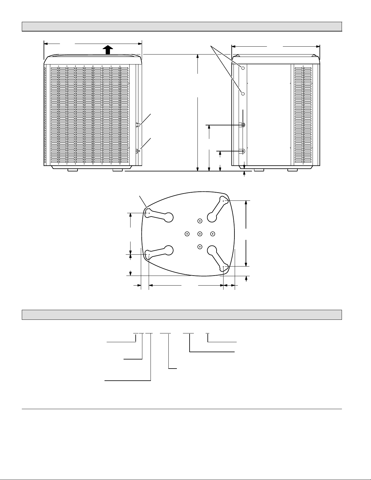
Unit Dimensions − Inches (mm) and Parts Arrangement
39.40"
(1003)
DISCHARGE AIR
SIDE VIEW
UNIT SUPPORT
FEET
ELECTRICAL INLETS
SUCTION LINE
INLET
LIQUID
LINE
INLET
[−024] 41 (1040)
[−030 THROUGH
−060] 47 (1194)
18.60"
(470)
8.00" (203)
1 (25)
35.50"
(902)
ACCESS VIEW
Model Number Identification
Refrigerant Type
X = R−410A
Unit Type
C = Air Conditioner
Series
16−7/8
(429)
8−3/4
(222)
3−1/8
(79)
BASE WITH ELONGATED LEGS
C 17 036− −
X 2−
26−7/8
3−3/4 (95)
30−3/4
(781)
4−5/8
(117)
230
Voltage
230 = 208/230V−1ph−60hz
Nominal Cooling Capacity
024 = 2 tons
030 = 2.5 tons
036 = 3 tons
042 = 3.5 tons
048 = 4 tons
060 = 5 tons
(683)
Minor Revision Number
506510−01
Page 2
Page 3
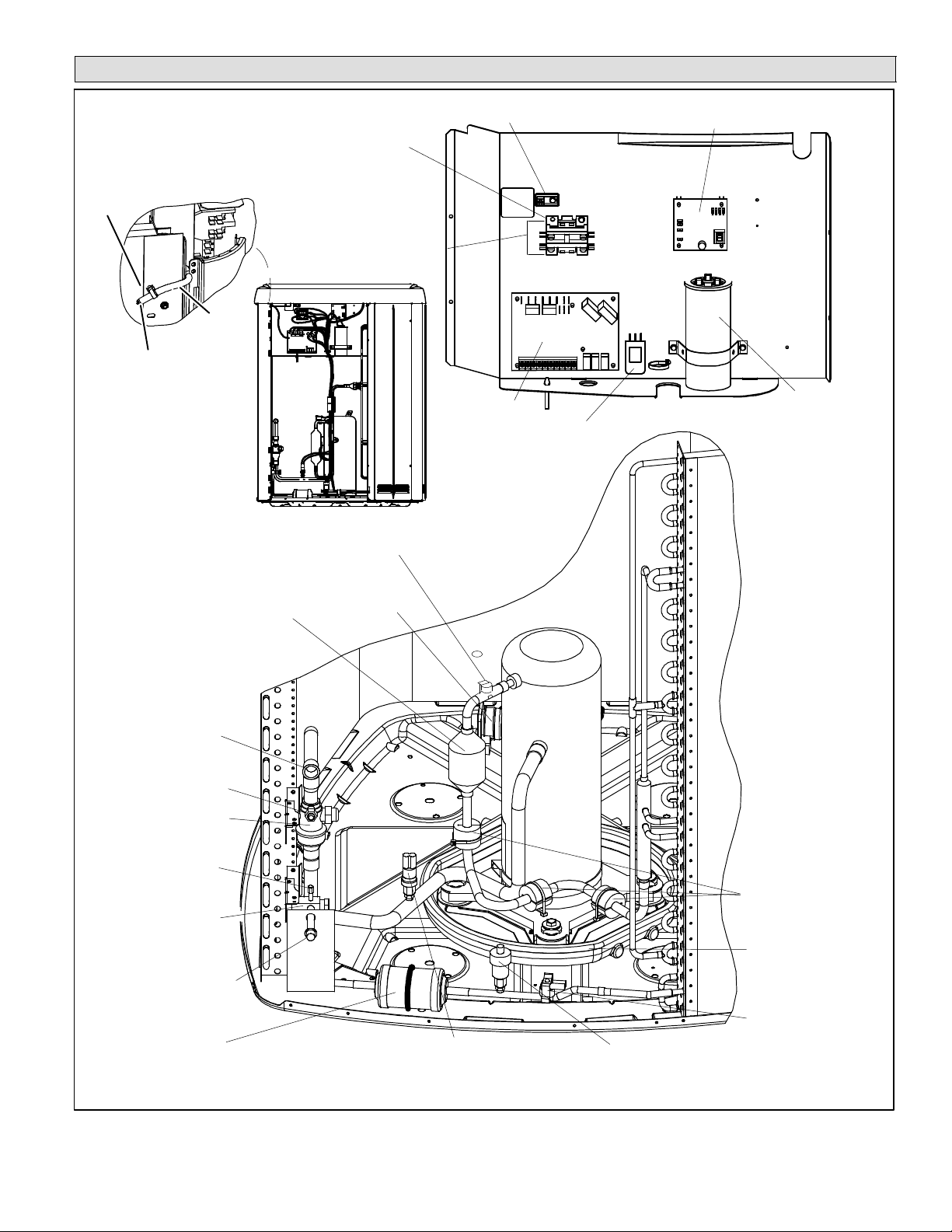
Typical Unit Parts Arrangement
CONTACTOR−1POLE (K1−1)
WIRE TIE
HIGH VOLTAGE FIELD
SLEEVE
OUTDOOR AMBIENT
TEMPERATURE
SENSOR
CONNECTIONS
GROUND LUG
MAIN CONTROL
FAN MOTOR SURGE
PROTECTION
FAN MOTOR CONTROL
PULSE−WIDTH MODULATION (PWM)
CAPACITOR (C12)
CONTROL BOX
HIGH PRESSURE SWITCH
FIELD CONNECTION
FOR SUCTION LINE
SUCTION LINE SERVICE
SUCTION LINE SERVICE
LIQUID LINE SERVICE
LIQUID LINE SERVICE
FOR LIQUID LINE SET
VALVE PORT
VALV E
VALVE PORT
VALV E
FIELD CONNECTION
MUFFLER
HIGH DISCHARGE
LINE TEMPERATURE
SENSOR
COMPRESSOR
HARNESS
VIBRATION ISOLATOR
SLEEVE LOCATIONS (DO
NOT REMOVE)
SR1 SOUND DOME
LIQUID LINE FILTER
DRIER (SINGLE FLOW)
LOW PRESSURE SWITCH
HIGH PRESSURE SWITCH
PLUMBING, SWITCHES AND SENSOR COMPONENTS
Figure 1. Typical Parts Arrangements
Page 3
THERMOSTAT
XC17 SERIES
Page 4
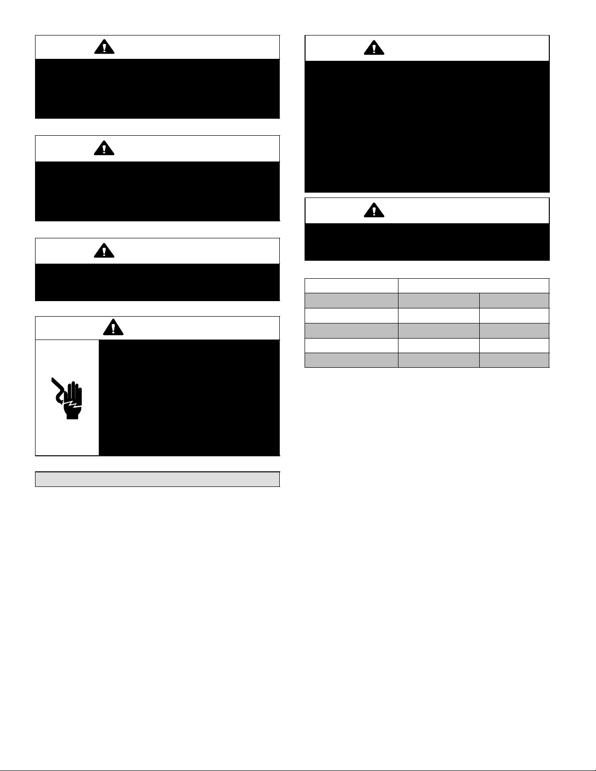
CAUTION
IMPORTANT
Physical contact with metal edges and corners while
applying excessive force or rapid motion can result in
personal injury. Be aware of, and use caution when
working near these areas during installation or while
servicing this equipment.
IMPORTANT
The Clean Air Act of 1990 bans the intentional venting of
refrigerant (CFCs, HCFCs AND HFCs) as of July 1,
1992. Approved methods of recovery, recycling or
reclaiming must be followed. Fines and/or incarceration
may be levied for noncompliance.
IMPORTANT
This unit must be matched with an indoor coil as
specified in Lennox’ Engineering Handbook. Coils
previously charged with HCFC−22 must be flushed.
WARNING
Electric Shock Hazard. Can cause injury
or death. Unit must be grounded in
accordance with national and local
codes.
Line voltage is present at all components
when unit is not in operation on units with
single-pole contactors. Disconnect all
remote electric power supplies before
opening access panel. Unit may have
multiple power supplies.
Operating Gauge Set and Service Valves
These instructions are intended as a general guide and do
not supersede local codes in any way. Consult authorities
who have jurisdiction before installation.
TORQUE REQUIREMENTS
When servicing or repairing heating, ventilating, and air
conditioning components, ensure the fasteners are
appropriately tightened. Table 1 lists torque values for
fasteners.
Only use Allen wrenches of sufficient hardness (50Rc −
Rockwell Harness Scale minimum). Fully insert the
wrench into the valve stem recess.
Service valve stems are factory−torqued (from 9 ft−lbs for
small valves, to 25 ft−lbs for large valves) to prevent
refrigerant loss during shipping and handling. Using an
Allen wrench rated at less than 50Rc risks rounding or
breaking off the wrench, or stripping the valve stem
recess.
See the Lennox Service and Application Notes #C−08−1
for further details and information.
IMPORTANT
To prevent stripping of the various caps used, the
appropriately sized wrench should be used and fitted
snugly over the cap before tightening.
Table 1. Torque Requirements
Parts Recommended Torque
Service valve cap 8 ft.− lb. 11 NM
Sheet metal screws 16 in.− lb. 2 NM
Machine screws #10 28 in.− lb. 3 NM
Compressor bolts 90 in.− lb. 10 NM
Gauge port seal cap 8 ft.− lb. 11 NM
USING MANIFOLD GAUGE SET
When checking the system charge, only use a manifold
gauge set that features low loss anti−blow back fittings.
Manifold gauge set used with HFC−410A refrigerant
systems must be capable of handling the higher system
operating pressures. The gauges should be rated for use
with pressures of 0 − 800 psig on the high side and a low
side of 30" vacuum to 250 psig with dampened speed to
500 psi. Gauge hoses must be rated for use at up to 800
psig of pressure with a 4000 psig burst rating.
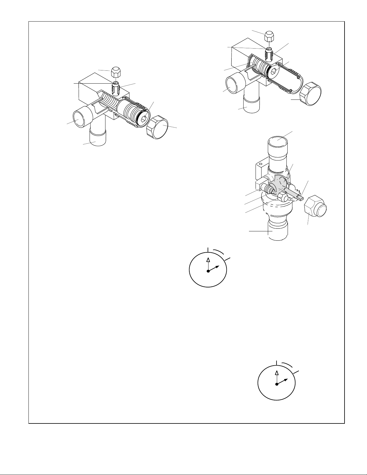
OPERATING SERVICE VALVES
The liquid and vapor line service valves are used for
removing refrigerant, flushing, leak testing, evacuating,
checking charge and charging.
Each valve is equipped with a service port which has a
factory−installed valve stem. Figure 2 provides information
on how to access and operating both angle and ball service
valves.
506510−01
Page 4
Page 5
SERVICE VALVES
VARIOUS TYPES
OPEN TO BOTH INDOOR AND
OUTDOOR UNITS
SERVICE PORT CAP
SERVICE PORT
TO INDOOR
CORE
UNIT
SERVICE PORT
(VALVE STEM
SHOWN OPEN)
INSERT HEX
WRENCH HERE
STEM CAP
SERVICE PORT CAP
SERVICE PORT
CORE
VALVE STEM
FRONT-SEATED
TO INDOOR
UNIT
TO OUTDOOR
UNIT
(FRONT−SEATED
STEM CAP
ANGLE−TYPE
SERVICE VALVE
CLOSED)
SERVICE PORT
(VALVE STEM SHOWN
CLOSED) INSERT HEX
WRENCH HERE
CLOSED TO BOTH
INDOOR AND OUTDOOR
UNITS
TO INDOOR UNIT
TO OUTDOOR UNIT
WHEN SERVICE VALVE IS CLOSED, THE SERVICE PORT IS OPEN TO THE
LINE SET AND INDOOR UNIT.
WHEN SERVICE VALVE IS OPEN, THE SERVICE PORT IS OPEN TO LINE SET,
INDOOR AND OUTDOOR UNIT.
ANGLE−TYPE SERVICE VALVE
(BACK−SEATED OPENED)
TO OPEN ROTATE STEM
COUNTERCLOCKWISE 90°.
TO CLOSE ROTATE STEM
CLOCKWISE 90°.
SERVICE PORT
SERVICE PORT CORE
SERVICE PORT CAP
To Access Service Port:
A service port cap protects the service port core from contamination and
serves as the primary leak seal.
1. Remove service port cap with an appropriately sized wrench.
2. Connect gauge set to service port.
3. When testing is completed, replace service port cap and tighten as follows:
S With Torque Wrench: Finger tighten and torque cap per Table 1.
S Without Torque Wrench: Finger tighten and use an appropriately
sized wrench to turn an additional 1/6 turn clockwise.
TO OUTDOOR UNIT
12
11
10
9
8
7
6
1/6 TURN
1
2
3
4
5
Operating Angle Type Service Valve:
1. Remove stem cap with an appropriately sized wrench.
2. Use a service wrench with a hex−head extension (3/16" for liquid line valve sizes and 5/16" for vapor line valve
sizes) to back the stem out counterclockwise as far as it will go.
BALL (SHOWN CLOSED)
BALL−TYPE SERVICE
VAL VE
VALVE STEM
STEM CAP
Operating Ball Type Service Valve:
1. Remove stem cap with an appropriately sized wrench.
2. Use an appropriately sized wrenched to open. To open valve, rotate stem counterclockwise 90°. To close rotate stem clockwise 90°.
Reinstall Stem Cap:
Stem cap protects the valve stem from damage and serves as the primary seal. Replace the stem cap and
tighten as follows:
S With Torque Wrench: Finger tighten and then torque cap per Table 1.
S Without Torque Wrench: Finger tighten and use an appropriately sized wrench to turn
an additional 1/12 turn clockwise.
NOTE A label with specific torque requirements may be affixed to the stem cap. If the label is present, use the specified torque.
10
9
8
11
1/6 TURN
12
1
2
3
4
5
7
6
Figure 2. Angle and Ball Service Valves
Page 5
XC17 SERIES
Page 6
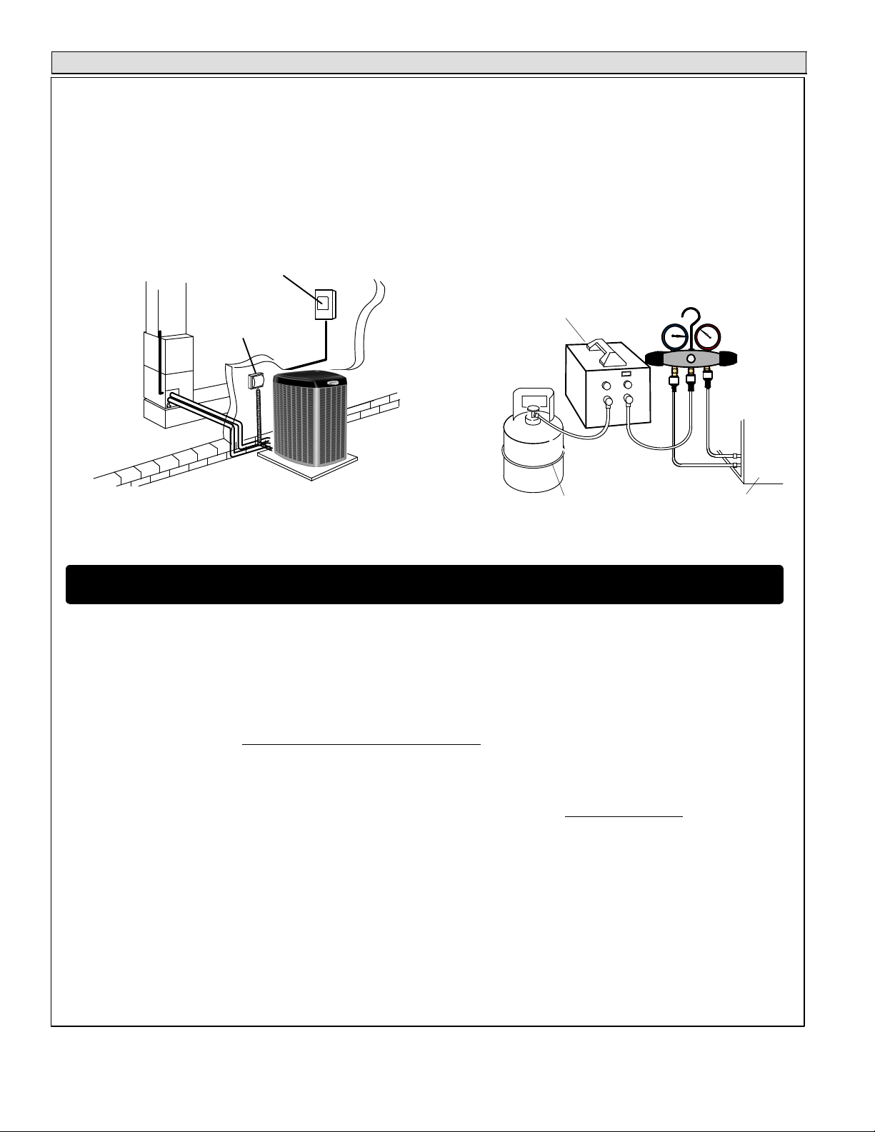
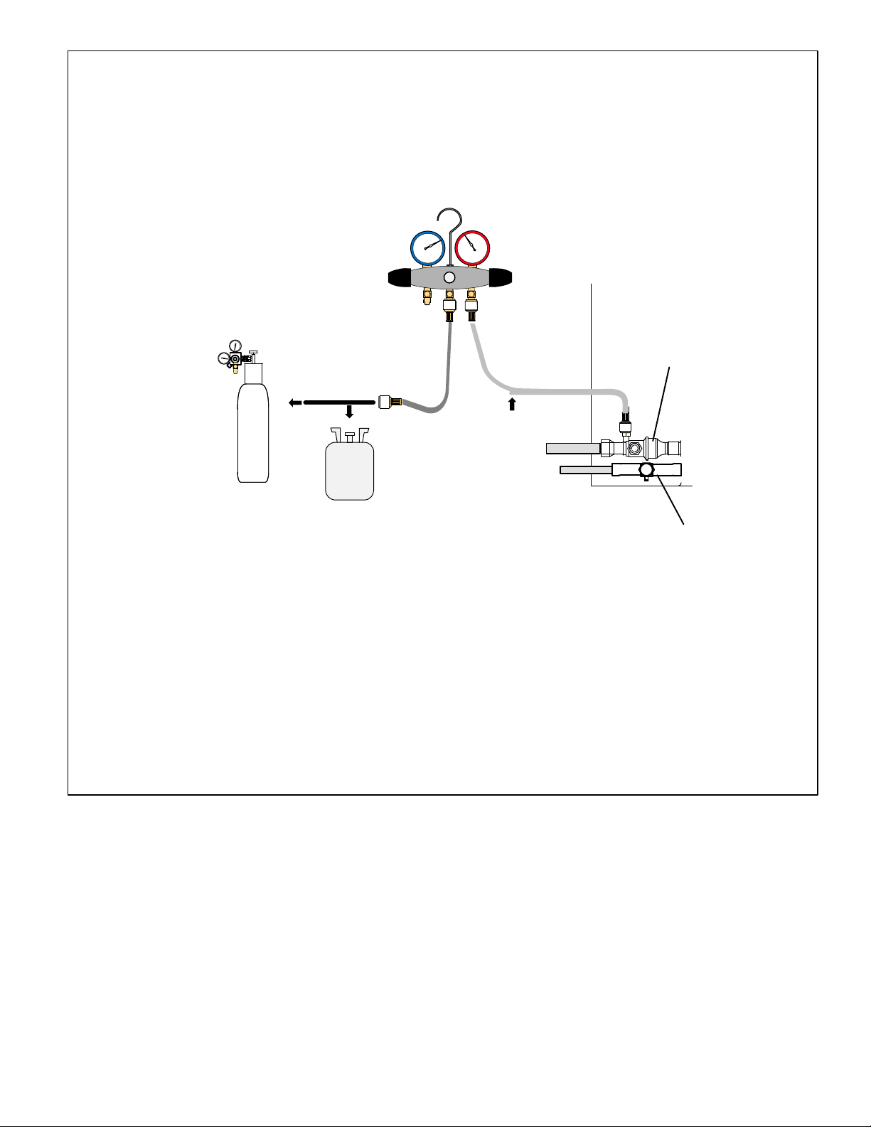
Recovering Refrigerant from Existing System
RECOVERING
REFRIGERANT FROM SYSTEM
DISCONNECT POWER
Disconnect all power to the existing outdoor unit at the disconnect
1
switch or main fuse box/breaker panel.
MAIN FUSE BOX/BREAKER PANEL
SERVICE
DISCONNECT
SWITCH
RECOVERING REFRIGERANT
Remove existing HCFC−22 refrigerant using one of the following procedures:
3
IMPORTANT Some system configurations may contain higher than normal refrigerant charge due to either large internal coil volumes,
and/or long line sets.
CONNECT MANIFOLD GAUGE SET
Connect a gauge set, clean recovery cylinder and a recovery
2
machine to the service ports of the existing unit. Use the
instructions provided with the recovery machine to make the
connections.
MANIFOLD GAUGES
RECOVERY MACHINE
LOW
CLEAN RECOVERY
CYLINDER
OUTDOOR UNIT
HIGH
METHOD 1:
Us this method if the existing outdoor unit is not equipped with shut−off valves, or if the unit is not operational and you plan to use the existing
HCFC−22 to flush the system.
Remove all HCFC−22 refrigerant from the existing system. Check gauges after shutdown to confirm that the entire system is completely void of
refrigerant.
METHOD 2:
Use this method if the existing outdoor unit is equipped with manual shut−off valves, and you plan to use new HCFC−22 refrigerant to flush the
system.
The following devices could prevent full system charge recovery into the outdoor unit:
S Outdoor unit’s high or low−pressure switches (if applicable) when tripped can cycle the compressor OFF.
S Compressor can stop pumping due to tripped internal pressure relief valve.
S Compressor has internal vacuum protection that is designed to unload the scrolls (compressor stops pumping) when the pressure ratio meets
a certain value or when the suction pressure is as high as 20 psig. (Compressor suction pressures should never be allowed to go into a vacuum.
Prolonged operation at low suction pressures will result in overheating of the scrolls and permanent damage to the scroll tips, drive bearings and
internal seals.)
Once the compressor can not pump down to a lower pressure due to one of the above system conditions, shut off the vapor valve. Turn OFF the
main power to unit and use a recovery machine to recover any refrigerant left in the indoor coil and line set.
Perform the following task:
A Start the existing HCFC−22 system in the cooling mode and close the liquid line valve.
B Use the compressor to pump as much of the existing HCFC−22 refrigerant into the outdoor unit until the outdoor system is full. Turn the outdoor unit
main power OFF and use a recovery machine to remove the remaining refrigerant from the system.
NOTE It may be necessary to bypass the low pressure switches (if equipped) to ensure complete refrigerant evacuation.
C When the low side system pressures reach 0 psig, close the vapor line valve.
D Check gauges after shutdown to confirm that the valves are not allowing refrigerant to flow back into the low side of the system.
506510−01
Page 6
Page 7
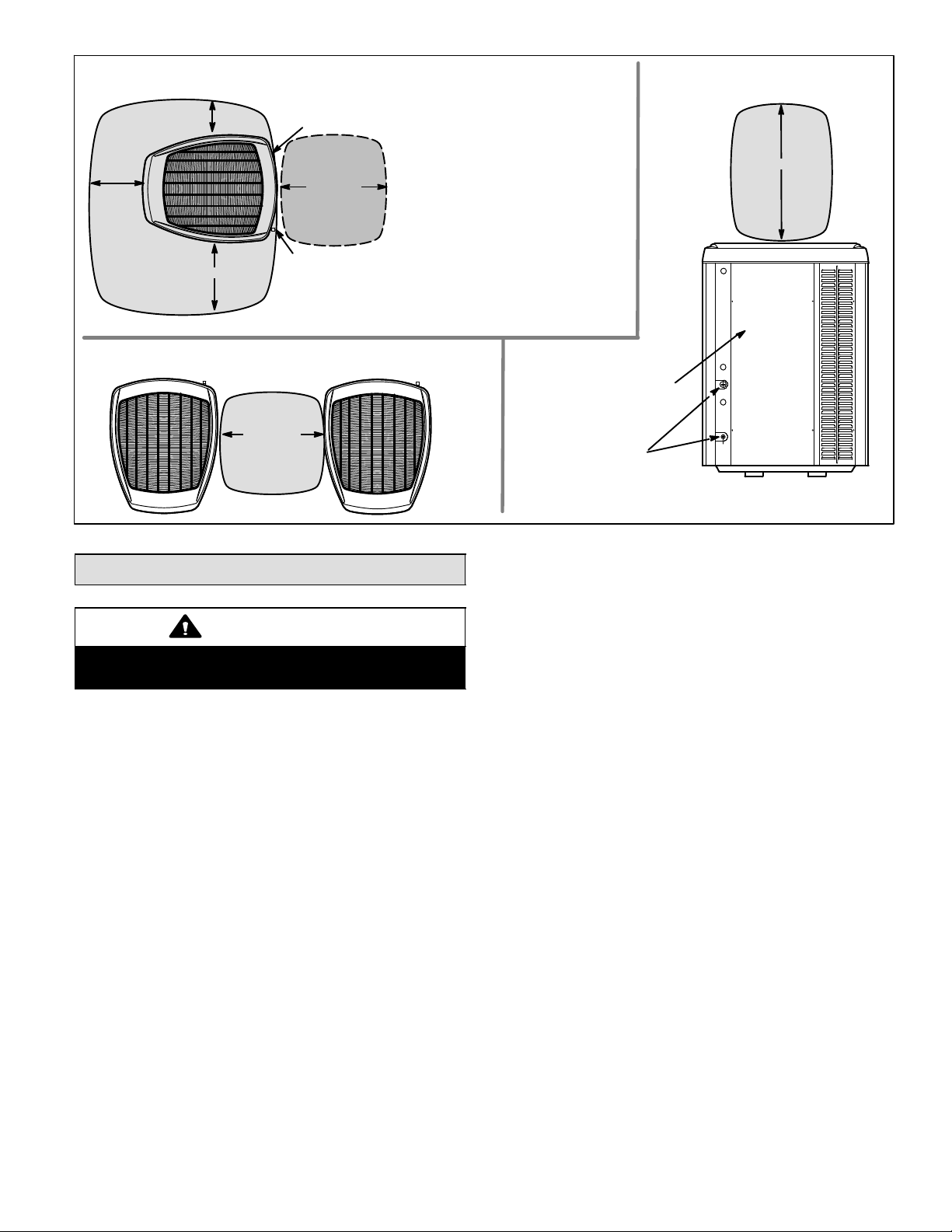
CLEARANCE ON ALL SIDES INCHES (MILLIMETERS)
MINIMUM CLEARANCE
ABOVE UNIT
6 (152)
12 (305)
36 (914)
ACCESS PANEL
CONTROL PANEL
ACCESS
LOCATION
30 (762)
LINE SET
CONNECTIONS
MINIMUM CLEARANCE BETWEEN
TWO UNITS
24 (610)
New Outdoor Unit Placement
NOTES:
S Clearance to one of the other three
sides must be 36 inches (914mm).
S Clearance to one of the remaining
two sides may be 12 inches
(305mm) and the final side may be
6 inches (152mm).
ACCESS PANEL
LINE SET
CONNECTIONS
Figure 3. Installation Clearances
property, not from the installation property. Install the
unit as far as possible from the property line.
48 (1219)
REAR VIEW OF UNIT
CAUTION
In order to avoid injury, take proper precaution when
lifting heavy objects.
See Unit Dimensions on page 3 for sizing mounting slab,
platforms or supports. Refer to Figure 3 for mandatory
installation clearance requirements.
POSITIONING CONSIDERATIONS
Consider the following when positioning the unit:
S Some localities are adopting sound ordinances based
on the unit’s sound level registered from the adjacent
S When possible, do not install the unit directly outside
a window. Glass has a very high level of sound
transmission. For proper placement of unit in relation
to a window see the provided illustration in Figure 4,
Detail A.
PLACING UNIT ON SLAB
When installing unit at grade level, the top of the slab
should be high enough above grade so that water from
higher ground will not collect around the unit. The slab
should have a slope tolerance as described in Figure 4,
Detail B.
NOTE If necessary for stability, anchor unit to slab as
described in Figure 4, Detail D.
Page 7
XC17 SERIES
Page 8
ELEVATING THE UNIT
Units are outfitted with elongated support feet as illustrated
in Figure 4, Detail C.
If additional elevation is necessary, raise the unit by
extending the height of the unit support feet. This may be
achieved by using a 2 inch (50.8mm) Schedule 40 female
threaded adapter.
The specified coupling will fit snuggly into the recessed
portion of the feet. Use additional 2 inch (50.8mm)
Schedule 40 male threaded adaptors which can be
threaded into the female threaded adaptors to make
additional adjustments to the level of the unit.
NOTE Keep the height of extenders short enough to
ensure a sturdy installation. If it is necessary to extend
further, consider a different type of field−fabricated
framework that is sturdy enough for greater heights.
STABILIZING UNIT ON UNEVEN SURFACES
IMPORTANT
Unit Stabilizer Bracket Use (field−provided):
Always use stabilizers when unit is raised above the
factory height. (Elevated units could become unstable in
gusty wind conditions).
Stabilizers may be used on factory height units when
mounted on unstable an uneven surface.
With unit positioned at installation site, perform the
following:
1. Remove two side louvered panels to expose the unit
base.
2. Install the brackets as illustrated in Figure 4, Detail D
using conventional practices.
3. Replace the panels after installation is complete.
ROOF MOUNTING
Install the unit a minimum of 6 inches (152 mm) above the
roof surface to avoid ice build−up around the unit. Locate
the unit above a load bearing wall or area of the roof that
can adequately support the unit. Consult local codes for
rooftop applications.
If unit coil cannot be mounted away from prevailing winter
winds, a wind barrier should be constructed. Size barrier at
least the same height and width as outdoor unit. Mount
barrier 24 inches (610 mm) from the sides of the unit in the
direction of prevailing winds.
NOTICE
Roof Damage!
This system contains both refrigerant and oil. Some
rubber roofing material may absorb oil and cause the
rubber to swell when it comes into contact with oil. The
rubber will then bubble and could cause leaks. Protect
the roof surface to avoid exposure to refrigerant and oil
during service and installation. Failure to follow this
notice could result in damage to roof surface.
506510−01
Page 8
Page 9
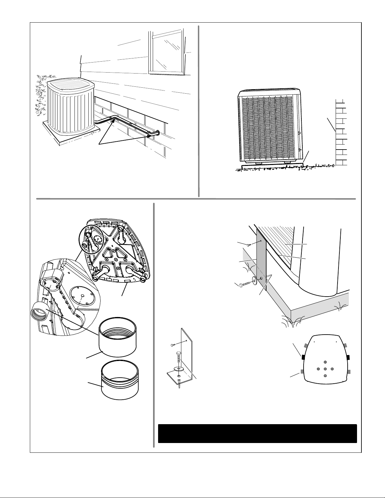
DETAIL A
INSTALL UNIT AWAY FROM WINDOWS
DETAIL B
INSTALL UNIT LEVEL OR, IF ON A SLOPE, MAINTAIN SLOPE TOLERANCE
OF 2 DEGREES (OR 2 INCHES PER 5 FEET [50 MM PER 1.5 M]) AWAY
FROM BUILDING STRUCTURE.
BUILDING
STRUCTURE
TWO 90° ELBOWS INSTALLED IN LINE SET WILL
REDUCE LINE SET VIBRATION.
Outside Unit Placement
DETAIL C
BASE
GROUND LEVEL
Slab Mounting at Ground Level
DETAIL D
Slab Side Mounting
#10 1/2" LONG SELF−DRILLING
SHEET METAL SCREWS
STABILIZING BRACKET (18 GAUGE
METAL 2" WIDTH; HEIGHT AS
#10 1−1/4" LONG HEX HD SCREW
CONCRETE SLAB USE TWO PLASTIC
ANCHORS (HOLE DRILL 1/4")
WOOD OR PLASTIC SLAB NO PLASTIC ANCHOR
(HOLE DRILL 1/8")
REQUIRED)
AND FLAT WASHER
MOUNTING
SLAB
COIL
BASE PAN
CORNER POST
LEG DETAIL
2" (50.8MM) SCH 40
FEMALE THREADED
Use additional 2" SCH 40 male threaded adapters
which can be threaded into the female threaded
adapters to make additional adjustments to the level
of the unit.
ADAPTER
2" (50.8MM) SCH 40
MALE THREADED
ADAPTER
Elevated Slab Mounting using Feet
Extenders
Figure 4. Placement, Slab Mounting and Stabilizing Unit
MINIMUM ONE
Deck Top Mounting
STABILIZING BRACKET (18 GAUGE METAL
2" (50.8MM) WIDTH; HEIGHT AS
REQUIRED); BEND TO FORM RIGHT ANGLE
SAME FASTENERS AS
SLAB SIDE MOUNTING.
ONE BRACKET PER SIDE (MIN.); FOR EXTRA STABILITY, TWO
BRACKETS PER SIDE, 2" (50.8MM) FROM EACH CORNER.
PER SIDE
FOR EXTRA
STABILITY
Stabilizing Unit on Uneven Surfaces
IMPORTANT To help stabilize an outdoor unit, some installations may require strap-
ping the unit to the pad using brackets and anchors commonly available in the marketplace.
Page 9
XC17 SERIES
Page 10
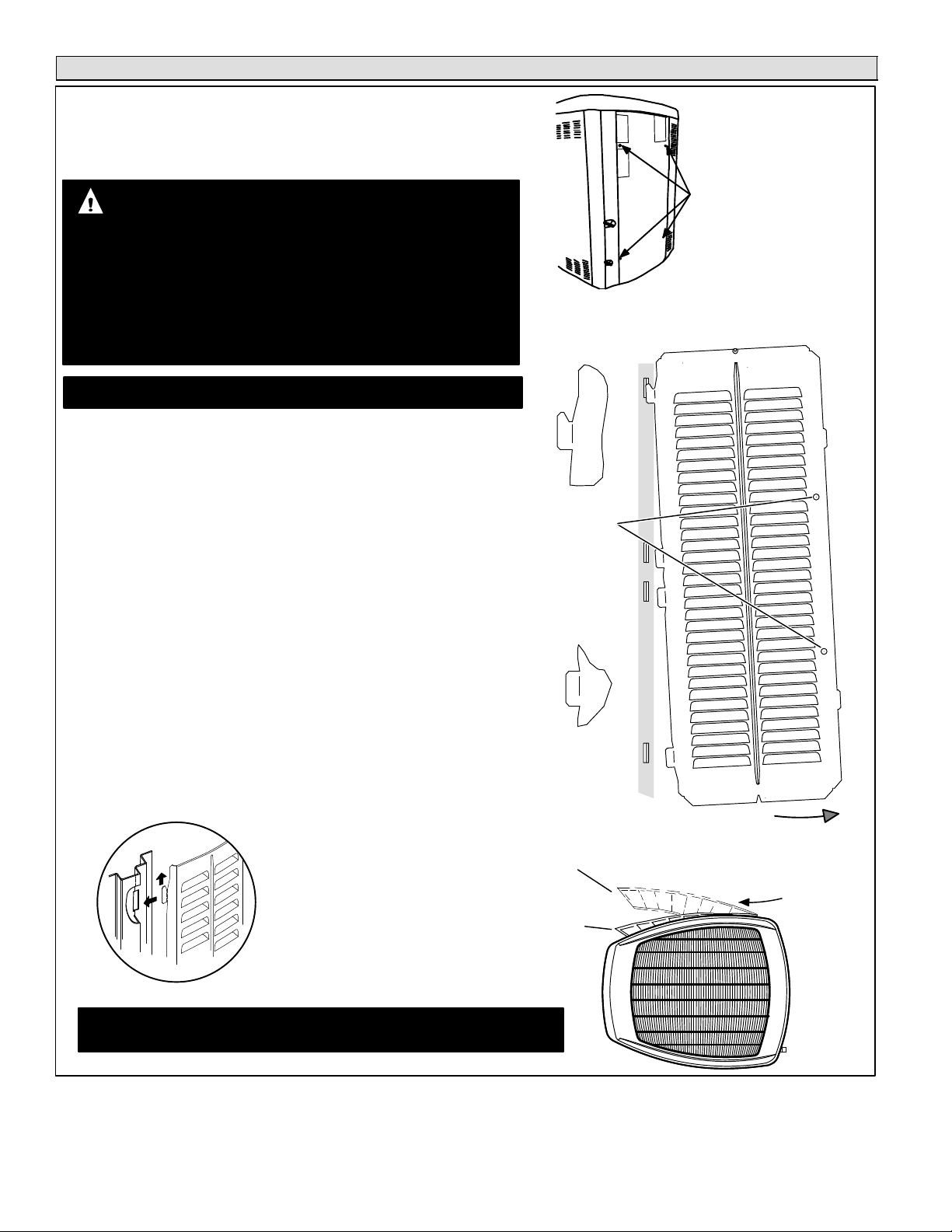
Removing and Installing Panels
ACCESS PANEL REMOVAL
Removal and reinstallation of the access
PANELS
ACCESS AND LOUVERED
WARNING
To prevent personal injury, or damage to panels, unit or structure, be sure to observe
the following:
While installing or servicing this unit, carefully stow all removed panels out of the
way, so that the panels will not cause injury to personnel, nor cause damage to objects or structures nearby, nor will the panels be subjected to damage (e.g., being
bent or scratched).
While handling or stowing the panels, consider any weather conditions, especially
windy conditions, that may cause panels to be blown around and battered.
panel is as illustrated.
Detail A
REMOVE 4 SCREWS TO
REMOVE PANEL FOR
ACCESSING COMPRESSOR
AND CONTROLS.
POSITION PANEL WITH HOLES
ALIGNED; INSTALL SCREWS
AND TIGHTEN.
IMPORTANT Do not allow panels to hang on unit by top tab. Tab is for alignment and not designed to support weight of panel.
PANEL SHOWN SLIGHTLY ROTATED TO ALLOW TOP TAB TO EXIT (OR ENTER) TOP SLOT
FOR REMOVING (OR INSTALLING) PANEL.
LOUVERED PANEL REMOVAL
Remove the louvered panels as follows:
1. Remove two screws, allowing the panel to swing open slightly.
2. Hold the panel firmly throughout this procedure. Rotate bottom corner of panel
away from hinged corner post until lower three tabs clear the slots as illustrated in
Detail B.
3. Move panel down until lip of upper tab clears the top slot in corner post as illustrated
in Detail A.
LOUVERED PANEL INSTALLATION
Position the panel almost parallel with the unit as illustrated in Detail D with the screw
side as close to the unit as possible. Then, in a continuous motion:
1. Slightly rotate and guide the lip of top tab inward as illustrated in Detail A and C;
then upward into the top slot of the hinge corner post.
2. Rotate panel to vertical to fully engage all tabs.
3. Holding the panel’s hinged side firmly in place, close the right−hand side of the panel, aligning the screw holes.
4. When panel is correctly positioned and aligned, insert the screws and tighten.
Detail C
MAINTAIN MINIMUM PANEL ANGLE (AS CLOSE TO PARALLEL
WITH THE UNIT AS POSSIBLE) WHILE INSTALLING PANEL.
Detail D
ANGLE MAY BE
TOO EXTREME
LIP
SCREW
HOLES
Detail B
ROTATE IN THIS DIRECTION; THEN
DOWN TO REMOVE PANEL
HOLD DOOR FIRMLY ALONG THE
HINGED SIDE TO MAINTAIN
FULLY−ENGAGED TABS
IMPORTANT To help stabilize an outdoor unit, some installations may require
strapping the unit to the pad using brackets and anchors commonly available in the
marketplace.
Page 10
506510−01
PREFERRED
ANGLE FOR
INSTALLATION
Page 11
New or Replacement Line Set
REFRIGERANT LINE SET
This section provides information on installation or
replacement of existing line set. If new or replacement line
set is not being installed then proceed to Brazing
Connections on page 13.
IMPORTANT
NOTE When installing refrigerant lines longer than 50
feet, see the Lennox Refrigerant Piping Design and
Fabrication Guidelines, CORP. 9351−L9, or contact
Lennox Technical Support Product Applications for
assistance.
IMPORTANT
Mineral oils are not compatible with HFC−410A. If oil
must be added, it must be a Polyol ester oil.
Lennox highly recommends changing line set when
converting the existing system from HCFC−22 to
HFC−410A. If that is not possible and the line set is the
proper size as reference in Table 2, use the procedure
outlined under Flushing the System on page 13.
If refrigerant lines are routed through a wall, then seal and
isolate the opening so vibration is not transmitted to the
building. Pay close attention to line set isolation during
installation of any HVAC system. When properly isolated
from building structures (walls, ceilings. floors), the
refrigerant lines will not create unnecessary vibration and
subsequent sounds. See Figure 5 for recommended
installation practices. Also, consider the following when
placing and installing a high−efficiency outdoor unit.
Liquid lines that meter the refrigerant, such as RFC1 liquid
lines, must not be used in this application. Existing line set
of proper size as listed in Table 2 may be reused. If system
was previously charged with HCFC−22 refrigerant, then
existing line set must be flushed (see Flushing the System
on page 14).
Field refrigerant piping consists of liquid and vapor lines
from the outdoor unit to the indoor unit coil (braze
connections). Use Lennox L15 (sweat, non−flare) series
line set, or field−fabricated refrigerant line sizes as listed in
Table 2.
Table 2. Refrigerant Line Set Inches (mm)
Field
Connections
Model
Size
−024
−030
−036
−042
−048
−060
NOTE Some applications may required a field provided 7/8" to
1−1/8" adapter
Liquid
Line
3/8
(10)
3/8
(10)
3/8
(10)
3/8
(10)
Vapor
Line
3/4
(19)
7/8
(22)
7/8
(22)
1−1/8.
(29)
Recommended Line Set
Liquid
Line
3/8
(10)
3/8
(10)
3/8
(10)
3/8
(10)
Vapor
Line
3/4
(19)
7/8
(22)
7/8
(22)
1−1/8
(29)
L15
Line Sets
Feet (Meters)
L15−41
15 − 50’ (5 − 15)
L15−65
15 − 50’ (5 − 15)
Field Fabricated
The compressor is charged with sufficient Polyol ester oil
for line set lengths up to 50 feet. If line set lengths longer
than 50 feet will be required, all one (1) ounce of oil for
every additional 10 feet of line set. Do not add any more
than seven (7) ounces of oil.
Recommended topping−off POE oils are Mobil EAL
ARCTIC 22 CC or ICI EMKARATEt RL32CF.
To obtain the correct information from Lennox, be sure to
communicate the following information:
S Model (XC17) and size of unit (e.g. −036).
S Line set diameters for the unit being installed as listed
in Table 2 and total length of installation.
S Number of elbows vertical rise or drop in the piping.
WARNING
Danger of fire. Bleeding the refrigerant
charge from only the high side may result
in the low side shell and suction tubing
being pressurized. Application of a
brazing torch while pressurized may
result in ignition of the refrigerant and oil
mixture − check the high and low
pressures before unbrazing.
WARNING
When using a high pressure gas such as
dry nitrogen to pressurize a refrigeration
or air conditioning system, use a
regulator that can control the pressure
down to 1 or 2 psig (6.9 to 13.8 kPa).
CAUTION
Brazing alloys and flux contain materials which are
hazardous to your health.
Avoid breathing vapors or fumes from brazing
operations. Perform operations only in well ventilated
areas.
Wear gloves and protective goggles or face shield to
protect against burns.
Wash hands with soap and water after handling brazing
alloys and flux.
Page 11
XC17 SERIES
Page 12
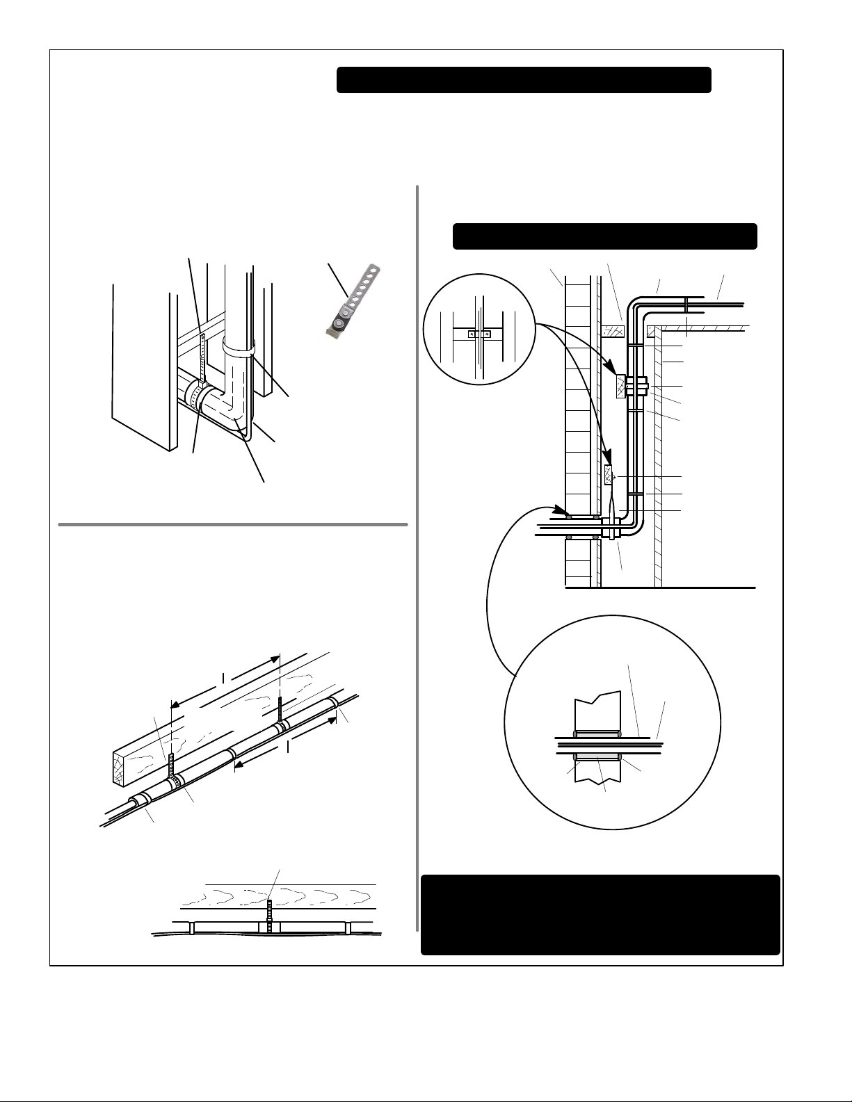
LINE SET
INSTALLATION
Line Set Isolation The following illustrations are
examples of proper refrigerant line set isolation:
REFRIGERANT LINE SET TRANSITION
FROM VERTICAL TO HORIZONTAL
ANCHORED HEAVY NYLON
WIRE TIE OR AUTOMOTIVE
MUFFLER-TYPE HANGER
AUTOMOTIVE
MUFFLER-TYPE HANGER
IMPORTANT Refrigerant lines must not contact structure.
REFRIGERANT LINE SET INSTALLING
VERTICAL RUNS (NEW CONSTRUCTION SHOWN)
NOTE Insulate liquid line when it is routed through areas where the
surrounding ambient temperature could become higher than the
temperature of the liquid line or when pressure drop is equal to or greater
than 20 psig.
IMPORTANT Refrigerant lines must not contact wall
OUTSIDE WALL
VAPOR LINE
LIQUID LINE
WALL
STUD
STRAP LIQUID LINE TO
VAPOR LINE
LIQUID LINE
NON−CORROSIVE
METAL SLEEVE
VAPOR LINE − WRAPPED
IN ARMAFLEX
REFRIGERANT LINE SET INSTALLING
HORIZONTAL RUNS
To hang line set from joist or rafter, use either metal strapping material
or anchored heavy nylon wire ties.
WIRE TIE (AROUND
VAPOR LINE ONLY)
8 FEET (2.43 METERS)
STRAPPING
MATERIAL (AROUND
VAPOR LINE ONLY)
TAPE OR
WIRE TIE
FLOOR JOIST OR
ROOF RAFTER
8 FEET (2.43 METERS)
NON−CORROSIVE
METAL SLEEVE
STRAP THE VAPOR LINE TO THE JOIST
OR RAFTER AT 8 FEET (2.43 METERS)
INTERVALS THEN STRAP THE LIQUID
LINE TO THE VAPOR LINE.
TAPE OR
WIRE TIE
WIRE TIE
INSIDE WALL
CAULK
LIQUID
LINE
STRAP
NON−CORROSIVE
METAL SLEEVE
WIRE TIE
WOOD BLOCK
WIRE TIE
STRAP
WOOD BLOCK
BETWEEN STUDS
SLEEVE
VAPOR LINE WRAPPED
WITH ARMAFLEX
OUTSIDE
WALL
PVC
PIPE
FIBERGLASS
INSULATION
NOTE Similar installation practices should be used if line set is
to be installed on exterior of outside wall.
FLOOR JOIST OR
506510−01
ROOF RAFTER
WARNING Polyol ester (POE) oils used with HFC−410A
refrigerant absorb moisture very quickly. It is very important that the
refrigerant system be kept closed as much as possible. DO NOT
remove line set caps or service valve stub caps until you are ready
to make connections.
Figure 5. Line Set Installation
Page 12
Page 13
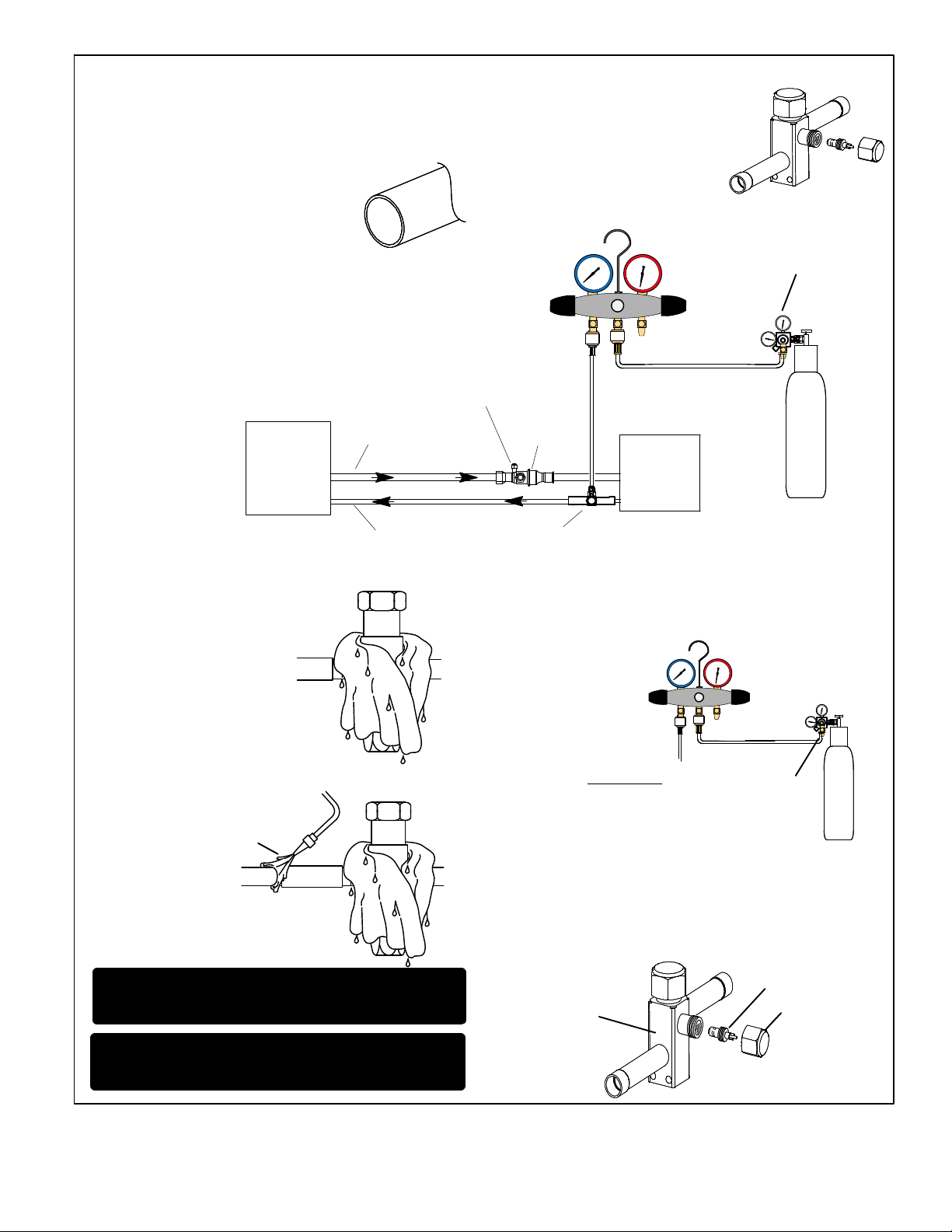
BRAZING
CONNECTIONS
CUT AND DEBUR
Cut ends of the refrigerant lines square
1
(free from nicks or dents) and debur the
ends. The pipe must remain round and do
not pinch end of the line.
ATTACHED GAUGES
A Connect gauge set low pressure side to liquid line service
3
valve.
B Connect gauge set center port to bottle of nitrogen with
regulator.
SERVICE PORT MUST BE OPEN TO ALLOW EXIT
INDOOR
UNIT
NOTE − Use silver alloy brazing rods with five or six percent minimum silver
alloy for copper−to−copper brazing, 45 percent alloy for copper−to−brass and
copper−to−steel brazing.
CAP AND CORE REMOVAL
Remove service cap and core
2
from both the vapor and liquid line
service ports.
HIGHLOW
B
ATTACH
POINT FOR NITROGEN
vapor LINE
GAUGES
VAPOR LINE
SERVICE
VALV E
OUTDOOR
UNIT
USE REGULATOR TO FLOW
NITROGEN AT 1 TO 2 PSIG.
WRAP SERVICE VALVE
To protect components during
4
brazing, wrap a wet cloth around
the liquid line service valve body
and copper tube stub and use
another wet cloth underneath the
valve body to protect the base
paint.
BRAZE LINE SET
Braze the liquid line to the liquid line
6
service valve. Turn off nitrogen flow.
POINT FLAME AWAY FROM
SERVICE VALVE
LIQUID LINE
LIQUID LINE SERVICE
5
NOTE The fixed orifice or check
expansion valve metering device at the
indoor unit will allow low pressure
nitrogen to flow through the system.
VALV E
FLOW NITROGEN
Flow regulated nitrogen (at 1 to 2 psig) through the refrigeration
gauge set into the valve stem port connection on the liquid line service
valve and out of the valve stem port connection on the vapor service
valve.
INSTALL SERVICE PORT CAPS ONLY
After all connections have been brazed, disconnect manifold gauge
7
set from service ports, cool down piping with wet rag and remove all
wrappings. Do not reinstall cores until after evacuation procedure.
Reinstall service port caps if desired to close off refrigerant ports.
A
LOW
NITROGEN
HIGH
USE REGULATOR TO
FLOW NITROGEN AT 1
TO 2 PSIG.
NITROGEN
WARNING Allow braze joint to cool before removing the wet
rag from the service valve. (TEMPERATURES ABOVE 250ºF
CAN DAMAGE VALVE SEALS
IMPORTANT Connect gauge set low pressure side to vapor
line service valve and repeat procedure starting at paragraph 4
for brazing the liquid line to service port valve.
Page 13
SERVICE PORT
SERVICE PORT CORE
SERVICE PORT CAP
XC17 SERIES
Page 14
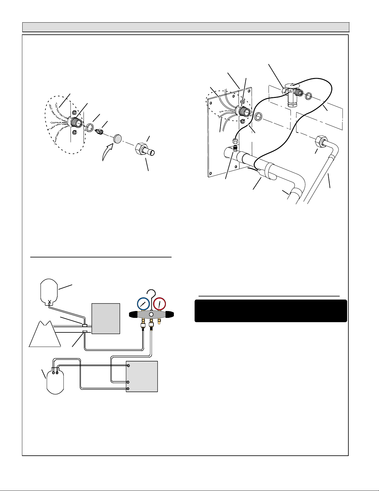
Flushing the System
FLUSHING
LINE SET AND INDOOR COIL (1 OF 2)
TYPICAL FIXED ORIFICE REMOVAL PROCEDURE
(Uncased Coil Shown)
1
DISTRIBUTOR TUBES
LIQUID LINE ORIFICE HOUSING
TEFLON RING
FIXED ORIFICE
TWO PIECE PATCH PLATE
(UNCASED COIL ONLY)
DISTRIBUTOR
TUBES
TYPICAL CHECK EXPANSION VALVE
REMOVAL PROCEDURE
(Uncased Coil Shown)
ORIFICE
HOUSING
STUB END
TEFLON
RING
CHECK
EXPANSION
VALV E
TEFLON
RING
LIQUID LINE
SENSING
LINE
BRASS NUT
DISTRIBUTOR
ASSEMBLY
A On fully cased coils, remove the coil access and plumbing panels.
B Remove any shipping clamps holding the liquid line and distributor
assembly.
C Using two wrenches, disconnect liquid line from liquid line orifice
housing. Take care not to twist or damage distributor tubes during
this process.
D Remove and discard fixed orifice, valve stem assembly if present
and Teflon washer as illustrated above.
E Use a field−provided fitting to temporary reconnect the liquid line to
the indoor unit’s liquid line orifice housing.
REMOVE AND DISCARD
WHITE TEFLON SEAL (IF
PRESENT)
LIQUID LINE ASSEMBLY
(INCLUDES STRAINER)
CONNECT GAUGES AND EQUIPMENT FOR
FLUSHING PROCEDURE
2
VAPOR LINE
SERVICE VALVE
EXISTING
INDOOR unit
INVERTED HCFC−22
CYLINDER CONTAINS
CLEAN HCFC−22 TO BE
USED FOR FLUSHING.
A
1
NEW
OUTDOOR
UNIT
LOW
OPENED
GAUGE
MANIFOLD
CLOSED
HIGH
B
LIQUID LINE SERVICE
RECOVERY
CYLINDER
A Inverted HCFC−22 cylinder with clean refrigerant to the vapor service
B HCFC−22 gauge set (low side) to the liquid line valve.
C HCFC−22 gauge set center port to inlet on the recovery machine with
D Connect recovery tank to recovery machines per machine
VALV E
VAPOR
LIQUID
C
D
valve.
an empty recovery tank to the gauge set.
instructions.
TANK
RETURN
INLET
DISCHARGE
RECOVERY MACHINE
OR
A On fully cased coils, remove the coil access and plumbing panels.
B Remove any shipping clamps holding the liquid line and distributor as-
C Disconnect the equalizer line from the check expansion valve equaliz-
D Remove the vapor line sensing bulb.
E Disconnect the liquid line from the check expansion valve at the liquid
F Disconnect the check expansion valve from the liquid line orifice hous-
G Remove and discard check expansion valve and the two Teflon rings.
H Use a field−provided fitting to temporary reconnect the liquid line to the
DISTRIBUTOR
ASSEMBLY
MALE EQUALIZER
LINE FITTING
SENSING BULB
sembly.
er line fitting on the vapor line.
line assembly.
ing. Take care not to twist or damage distributor tubes during this process.
indoor unit’s liquid line orifice housing.
CAUTION This procedure should not be performed on systems which contain contaminants (Example compressor burn
out.
EQUALIZER
LINE
ASSEMBLY WITH
VAPOR
LINE
LIQUID LINE
BRASS NUT
LIQUID
FLUSHING LINE SET
The line set and indoor unit coil must be flushed with at least the
3
same amount of clean refrigerant that previously charged the system. Check the charge in the flushing cylinder before proceeding.
B
A Set the recovery machine for liquid recovery and start the recov-
ery machine. Open the gauge set valves to allow the recovery
machine to pull a vacuum on the existing system line set and indoor unit coil.
B Invert the cylinder of clean HCFC−22 and open its valve to allow
liquid refrigerant to flow into the system through the vapor line
valve. Allow the refrigerant to pass from the cylinder and through
the line set and the indoor unit coil before it enters the recovery
machine.
C After all of the liquid refrigerant has been recovered, switch the
recovery machine to vapor recovery so that all of the HCFC−22
vapor is recovered. Allow the recovery machine to pull down to 0
the system.
D Close the valve on the inverted HCFC−22 drum and the gauge
set valves. Pump the remaining refrigerant out of the recovery
machine and turn the machine off.
LINE
506510−01
Page 14
Page 15
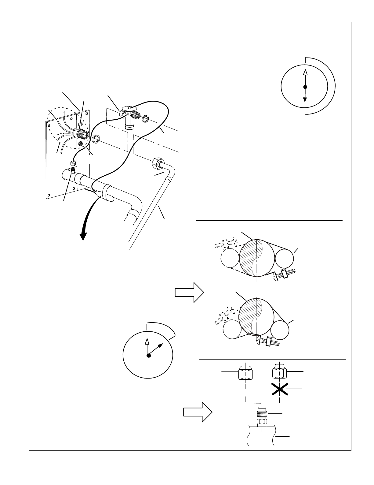
FLUSHING LINE SET AND INDOOR COIL (2 OF 2)
TYPICAL CHECK EXPANSION VALVE INSTALLATION PROCEDURE
This outdoor unit is designed for use in systems that use check expansion valve metering device. See the Lennox XC17 Engineering Handbook
4
for approved check expansion valve kit match−ups and application information.
The check expansion valve unit can be installed internal or
TWO PIECE
PATCH PLATE
(UNCASED
COIL ONLY)
DISTRIBUTOR
TUBES
DISTRIBUTOR
ASSEMBLY
MALE EQUALIZER LINE
FITTING (SEE
EQUALIZER LINE
INSTALLATION FOR
FURTHER DETAILS)
SENSING BULB INSULATION IS REQUIRED
IF MOUNTED EXTERNAL TO THE COIL
CASING. SENSING BULB INSTALLATION
FOR BULB POSITIONING.
(Uncased Coil Shown)
LIQUID LINE
ORIFICE
HOUSING
STUB
END
TEFLON
RING
EQUALIZER
LINE
CHECK
EXPANSION
VALV E
LIQUID LINE
ASSEMBLY WITH
BRASS NUT
VAPOR
LINE
external to the indoor coil. In applications where an uncased coil
is being installed in a field−provided plenum, install the check
expansion valve in a manner that will provide access for field
servicing of the check expansion valve. Refer to below
illustration for reference during installation of check expansion
valve unit.
TEFLON
RING
A Remove the field−provided fitting that temporary reconnected the liquid
line to the indoor unit’s distributor assembly.
SENSING
LINE
LIQUID LINE
B Install one of the provided Teflon rings around the stubbed end of the
check expansion valve and lightly lubricate the connector threads and
expose surface of the Teflon ring with refrigerant oil.
C Attach the stubbed end of the check expansion valve to the liquid line
orifice housing. Finger tighten and use an appropriately sized wrench to
turn an additional 1/2 turn clockwise as illustrated in the figure above, or
20 ft−lb.
D Place the remaining Teflon washer around the other end of the check
expansion valve. Lightly lubricate connector threads and expose surface of the Teflon ring with refrigerant oil.
E Attach the liquid line assembly to the check expansion valve. Finger
tighten and use an appropriately sized wrench to turn an additional 1/2
turn clockwise as illustrated in the figure above or 20 ft−lb.
VAPOR LINE
BULB
12
9
ON LINES SMALLER THAN 7/8",
MOUNT SENSING BULB AT
EITHER THE 3 OR 9 O’CLOCK
POSITION.
BULB
10
8
11
12
7
6
1/2 TURN
1
2
3
4
5
SENSING BULB INSTALLATION
A Attach the vapor line sensing bulb in the proper orientation
as illustrated to the right using the clamp and screws provided.
NOTE Confirm proper thermal contact between vapor line
and check expansion bulb before insulating the sensing bulb
once installed.
B Connect the equalizer line from the
check expansion valve to the
equalizer vapor port on the vapor
line. Finger tighten the flare nut
plus 1/8 turn (7 ft−lbs) as illustrated below.
9
10
8
11
12
7
6
EQUALIZER LINE INSTALLATION
A Remove and discard either the flare seal cap or flare nut
with copper flare seal bonnet from the equalizer line port
on the vapor line as illustrated in the figure to the right.
B Remove and discard either the flare seal cap or flare nut
with copper flare seal bonnet from the equalizer line port on
the vapor line as illustrated in the figure to the right.
1
5
1/8 TURN
2
3
4
VAPOR LINE
FLARE SEAL CAP
ON 7/8" AND LARGER LINES,
MOUNT SENSING BULB AT
EITHER THE 4 OR 8 O’CLOCK
12
BULB
NOTE NEVER MOUNT ON BOTTOM OF LINE.
OR
POSITION. NEVER MOUNT ON
BOTTOM OF LINE.
BULB
FLARE NUT
COPPER FLARE
SEAL BONNET
MALE BRASS EQUALIZER
LINE FITTING
VAPOR LINE
Page 15
XC17 SERIES
Page 16
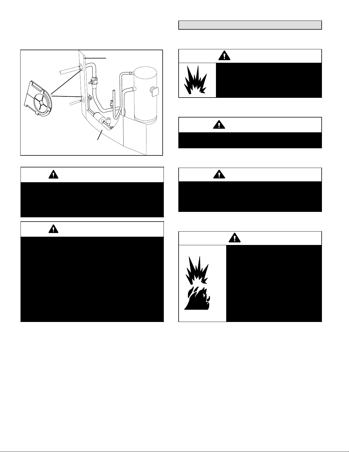
INSTALLING ISOLATION GROMMETS
Locate the isolation grommets (provided). Slide grommets
onto vapor and liquid lines. Insert grommets into piping
panel to isolate refrigerant lines from sheet metal edges.
Leak Testing the System
SUCTION LINE
LIQUID LINE
TWO ISOLATION GROMMETS ARE
PROVIDE FOR THE LIQUID AND
SUCTION LINE PIPE PANEL PASS
THROUGH.
REAR VIEW OF UNIT EXTERIOR
Figure 6. Isolation Grommets
PIPING PANEL
IMPORTANT
The Environmental Protection Agency (EPA) prohibits
the intentional venting of HFC refrigerants during
maintenance, service, repair and disposal of appliance.
Approved methods of recovery, recycling or reclaiming
must be followed.
WARNING
When using a high pressure gas such as
dry nitrogen to pressurize a refrigeration
or air conditioning system, use a
regulator that can control the pressure
down to 1 or 2 psig (6.9 to 13.8 kPa).
IMPORTANT
Leak detector must be capable of sensing HFC
refrigerant.
WARNING
Refrigerant can be harmful if it is inhaled. Refrigerant
must be used and recovered responsibly.
Failure to follow this warning may result in personal injury
or death.
IMPORTANT
If this unit is being matched with an approved line set
or indoor unit coil which was previously charged with
mineral oil, or if it is being matched with a coil which
was manufactured before January of 1999, the coil
and line set must be flushed prior to installation. Take
care to empty all existing traps. Polyol ester (POE) oils
are used in Lennox units charged with HFC−410A
refrigerant. Residual mineral oil can act as an
insulator, preventing proper heat transfer. It can also
clog the expansion device, and reduce the system
performance and capacity.
Failure to properly flush the system per the
instructions below will void the warranty.
WARNING
Fire, Explosion and Personal Safety
Hazard.
Failure to follow this warning could
result in damage, personal injury or
death.
Never use oxygen to pressurize or
purge refrigeration lines. Oxygen,
when exposed to a spark or open
flame, can cause damage by fire
and/or an explosion, that could result
in personal injury or death.
506510−01
Page 16
Page 17
LEAK TEST
LINE SET AND INDOOR COIL
CONNECT GAUGE SET
A Connect an HFC−410A manifold gauge set high
1
pressure hose to the vapor valve service port.
B With both manifold valves closed, connect the
cylinder of HFC−410A refrigerant to the center port
of the manifold gauge set.
NOTE Normally, the high pressure hose is connected to the liquid line port. However, connecting it to the vapor port better protects the manifold gauge set from high
pressure damage.
HIGHLOW
MANIFOLD GAUGE SET
NOTE Later in the procedure, the HFC−410A
container will be replaced by the nitrogen container.
B
TO VAPOR
SERVICE VALVE
NITROGEN
HFC−410A
TEST FOR LEAKS
After the line set has been connected to the indoor unit and air conditioner, check the line set connections and
2
indoor unit for leaks. Use the following procedure to test for leaks:
A With both manifold valves closed, connect the cylinder of HFC−410A refrigerant to the center port of the manifold gauge set. Open
the valve on the HFC−410A cylinder (vapor only).
B Open the high pressure side of the manifold to allow HFC−410A into the line set and indoor unit. Weigh in a trace amount of
HFC−410A. [A trace amount is a maximum of two ounces (57 g) refrigerant or three pounds (31 kPa) pressure]. Close the valve on
the HFC−410A cylinder and the valve on the high pressure side of the manifold gauge set. Disconnect the HFC−410A cylinder.
C Connect a cylinder of dry nitrogen with a pressure regulating valve to the center port of the manifold gauge set.
D Adjust dry nitrogen pressure to 150 psig (1034 kPa). Open the valve on the high side of the manifold gauge set in order to pressurize the
line set and the indoor unit.
E After a few minutes, open one of the service valve ports and verify that the refrigerant added to the system earlier is measurable
with a leak detector.
F After leak testing disconnect gauges from service ports.
OUTDOOR UNIT
VAPOR SERVICE VALVE
A
LIQUID LINE
SERVICE VALVE
Page 17
XC17 SERIES
Page 18

Evacuating the System
EVACUATING
LINE SET AND INDOOR COIL
CONNECT GAUGE SET
NOTE Remove cores from service valves (if not al-
1
ready done).
A Connect low side of manifold gauge set
with 1/4 SAE in−line tee to vapor line
service valve
B Connect high side of manifold gauge
set to liquid line service valve
C Connect micron gauge available
connector on the 1/4 SAE in−line tee.
D Connect the vacuum pump (with
vacuum gauge) to the center port of the
manifold gauge set. The center port line
will be used later for both the HFC−410A
and nitrogen containers.
LIQUID LINE
SERVICE VALVE
HFC−410A
VACUUM PUMP
OUTDOOR
VAPOR
SERVICE
VALV E
UNIT
A
B
A34000 1/4 SAE TEE WITH
SWIVEL COUPLER
500
C
D
MICRON
GAUGE
LOW
TO VAPOR
SERVICE VALVE
TO LIQUID LINE
SERVICE VALVE
MANIFOLD
GAUGE SET
HIGH
NITROGEN
EVACUATE THE SYSTEM
A Open both manifold valves and start the vacuum pump.
2
B Evacuate the line set and indoor unit to an absolute pressure of 23,000 microns (29.01 inches of mercury).
NOTE During the early stages of evacuation, it is desirable to close the manifold gauge valve at least once. A rapid rise in pressure
indicates a relatively large leak. If this occurs, repeat the leak testing procedure.
NOTE The ter m absolute pressure means the total actual pressure within a given volume or system, above the absolute zero of
pressure. Absolute pressure in a vacuum is equal to atmospheric pressure minus vacuum pressure.
C When the absolute pressure reaches 23,000 microns (29.01 inches of mercury), close the manifold gauge valves, turn off the vacuum
pump and disconnect the manifold gauge center port hose from vacuum pump. Attach the manifold center port hose to a dry nitrogen
cylinder with pressure regulator set to 150 psig (1034 kPa) and purge the hose. Open the manifold gauge valves to break the vacuum in
the line set and indoor unit. Close the manifold gauge valves.
D Shut off the dry nitrogen cylinder and remove the manifold gauge hose from the cylinder. Open the manifold gauge valves to release the
dry nitrogen from the line set and indoor unit.
E Reconnect the manifold gauge to the vacuum pump, turn the pump on, and continue to evacuate the line set and indoor unit until the
absolute pressure does not rise above 500 microns (29.9 inches of mercury) within a 20−minute period after shutting off the vacuum pump
and closing the manifold gauge valves.
F When the absolute pressure requirement above has been met, disconnect the manifold hose from the vacuum pump and connect it to an
upright cylinder of HFC−410A refrigerant. Open the manifold gauge valve 1 to 2 psig in order to release the vacuum in the line set and
indoor unit.
G Perform the following:
RECOMMEND
MINIMUM 3/8" HOSE
S Close manifold gauge valves.
S Shut off HFC−410A cylinder.
S Reinstall service valve cores by removing manifold hose from service valve. Quickly install cores with
core tool while maintaining a positive system pressure.
S Replace the stem caps and secure finger tight, then tighten an additional one−sixth (1/6) of a turn as
illustrated.
11
10
9
8
7
12
6
1/6 TURN
1
2
3
4
5
506510−01
Page 18
Page 19
IMPORTANT
Use a thermocouple or thermistor electronic vacuum
gauge that is calibrated in microns. Use an instrument
capable of accurately measuring down to 50 microns.
WARNING
Danger of Equipment Damage. Avoid deep vacuum
operation. Do not use compressors to evacuate a
system. Extremely low vacuums can cause internal
arcing and compressor failure. Damage caused by
deep vacuum operation will void warranty.
Evacuating the system of non−condensables is critical for
proper operation of the unit. Non−condensables are
defined as any gas that will not condense under
temperatures and pressures present during operation of
an air conditioning system. Non−condensables and water
suction combine with refrigerant to produce substances
that corrode copper piping and compressor parts.
Electrical
In the U.S.A., wiring must conform with current local codes
and the current National Electric Code (NEC). In Canada,
wiring must conform with current local codes and the current
Canadian Electrical Code (CEC).
Refer to the furnace or air handler installation instructions
for additional wiring application diagrams and refer to unit
nameplate for minimum circuit ampacity and maximum
overcurrent protection size.
24VAC TRANSFORMER
Use the transformer provided with the furnace or air
handler for low-voltage control power (24VAC − 40 VA
minimum)
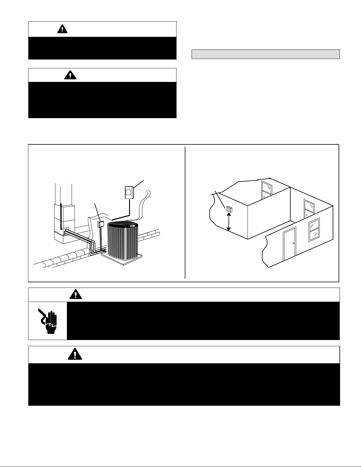
SIZE CIRCUIT AND INSTALL DISCONNECT
SWITCH
1
Refer to the unit nameplate for minimum circuit ampacity, and
maximum fuse or circuit breaker (HACR per NEC). Install power
wiring and properly sized disconnect switch.
SERVICE
DISCONNECT
SWITCH
NOTE Units are approved for use only with copper conductors.
Ground unit at disconnect switch or to an earth ground.
MAIN FUSE BOX/
BREAKER PANEL
WARNING
Electric Shock Hazard. Can cause injury or death. Unit must be grounded in accordance with national and
local codes.
Line voltage is present at all components when unit is not in operation on units with single-pole contactors.
Disconnect all remote electric power supplies before opening access panel. Unit may have multiple power
supplies.
INSTALL THERMOSTAT
Install room thermostat (ordered separately) on an inside wall
2
approximately in the center of the conditioned area and 5 feet
(1.5m) from the floor. It should not be installed on an outside wall
or where it can be affected by sunlight or drafts.
THERMOSTAT
5 FEET
(1.5M)
NOTE 24VAC, Class II circuit connections are made in the control
panel.
CAUTION
ELECTROSTATIC DISCHARGE
(ESD)
Precautions and Procedures
Electrostatic discharge can affect electronic components. Take precautions
during unit installation and service to protect the unit’s electronic controls.
Precautions will help to avoid control exposure to electrostatic discharge by
putting the unit, the control and the technician at the same electrostatic potential.
Neutralize electrostatic charge by touching hand and all tools on an unpainted unit
surface before performing any service procedure
Page 19
XC17 SERIES
Page 20

ROUTE CONTROL WIRES
Install low voltage control wiring from outdoor to indoor unit and from
3
thermostat to indoor unit as illustrated. See Figures 10 and 10 for
typical configurations.
A Run 24VAC control wires through hole with grommet.
B Make 24VAC control wire connections to Main Control.
NOTE Do not bundle any excess 24VAC control wires inside control
panel.
NOTE Wire tie provides low voltage wire strain relief and to maintain
separation of field installed low and high voltage circuits.
NOTE For proper voltages, select thermostat wire (control wires)
gauge per table below.
WIRE RUN LENGTH AWG# INSULATION TYPE
LESS THAN 100’ (30 METERS) 18 TEMPERATURE RATING
MORE THAN 100’ (30 METERS) 16 35ºC MINIMUM.
B
MAIN CONTROL
CONTROL PANEL
HOLE
A
ROUTE HIGH VOLTAGE AND GROUND WIRES
Any excess high voltage field wiring should be trimmed and secured away from any low voltage field wiring. To facilitate a conduit, a cutout is
4
located in the bottom of the control panel. Connect conduit to the control panel using a proper conduit fitting.
PIPING PANEL
HIGH VOLTAGE
CONDUIT HOLE
WATERTIGHT
CONDUIT
FITTING
WATERTIGHT
FLEXIBLE
CONDUIT
TO SERVICE
DISCONNECT BOX
CONTROL PANEL
GROUND LUG
CONTACTOR
ELECTRICAL INLET (CONTROL WIRING LOW VOLTAGE).
USE BUSHING PROVIDED IN BAG ASSEMBLY HERE.
ELECTRICAL INLET
(HIGH VOLTAGE)
WIRING ENTRY POINTS
ACCESS VIEW
506510−01
Page 20
Page 21
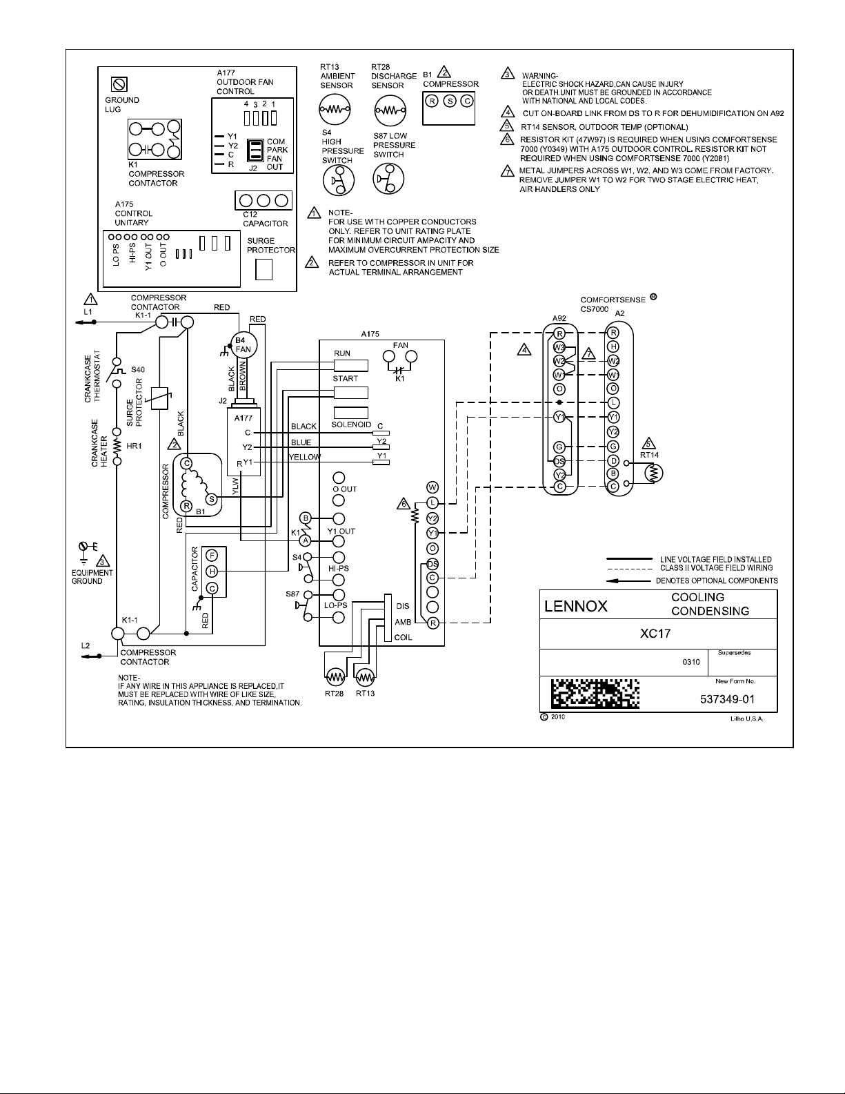
Figure 7. Typical XC17 Wiring
Page 21
XC17 SERIES
Page 22

Main Control Jumpers and Terminals
MAIN CONTROL AIR CONDITIONER ONE STAGE
TABLE 3 PROVIDES ADDITIONAL INFORMATION CONCERNING JUMPERS, LOOP, AND CONNECTIONS
FOR THE MAIN CONTROL.
DS11 and DS14
LED ALERT CODES
E12
E16
DS13 and DS15
LED ALERT CODES
TEST PINS
E33
506510−01
CUT FOR HUMIDITROL ENHANCED
DEHUMIDIFICATION ACCESSORY (EDA)
APPLICATIONS.
Figure 8. Control Jumpers, Loop and Terminals
Page 22
W1
Page 23
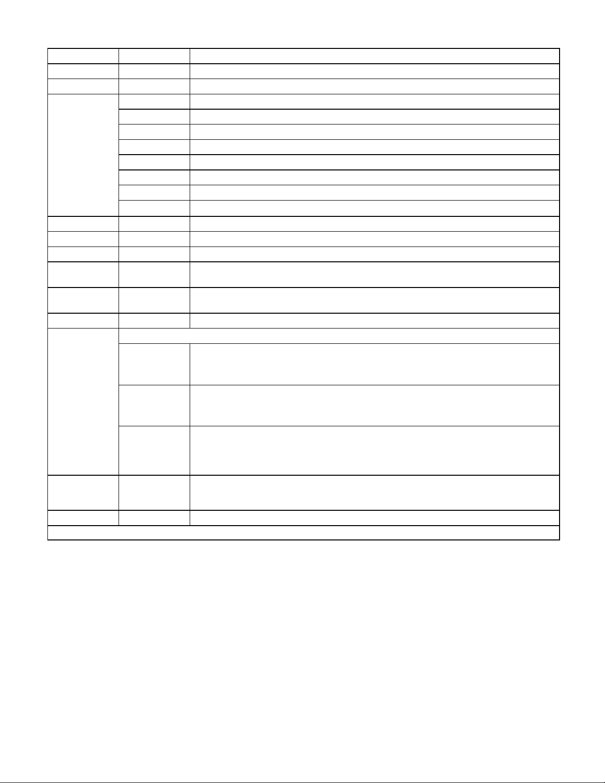
Table 3. Main Control Jumpers and Terminals
Board ID Label Description
E12 PSC Fan 240 VAC output connection for outdoor fan.
E16 PSC Fan 240 VAC input connection for outdoor fan.
W 24VAC output for defrost auxiliary heat output.
L Thermostat service light connection.
Y2 24VAC thermostat input/output for second stage operation of the unit.
E18
E21 and E22 LO−PS S4 connection for low−pressure switch (2.4 milliamps @ 18VAC)
E31 and E32 Y1 OUT 24VAC common output, switched for enabling compressor contactor.
E24 and E25 HS−PS S87 connection for high−pressure switch.
E26 FAN 1
E27 FAN 2
E28 FAN C ECM common connection for ECM fan.
E30
E33 Field Test
W1 Short DS To R Cut for Humiditrol Enhanced Dehumidification Accessory (EDA) applications.
* Factory default setting
Y1 24VAC thermostat input for first stage operation of the unit.
O 24VAC thermostat input for reversing valve operation
DS Humiditrol Input
C 24VAC system common
R
24VAC system power input
First Stage and second stage basic and precision dehumidification ECM fan motor 24VDC output connection 1.
Second stage basic and precision dehumidification ECM fan motor 24VDC output connection
2.
Six position square pin header E30 provides connections for the temperature sensors.
DIS 5 Discharge line temperature sensor supply.
DIS (YELLOW)
Pins 5 and 6
DIS 6 Discharge line temperature sensor return.
Range is −35ºF to 310ºF. Sensor is clipped on a 1/2" copper tube.
AMB (BLACK)
Pins 3 and 4
AMB 3 Outdoor ambient temperature sensor supply.
AMB 4 Outdoor ambient temperature return.
Range is −40ºF to +140ºF
COIL 1 Outdoor coil temperature sensor supply.
COIL (BROWN)
Pins 5 and 6
COIL 2 Outdoor coil temperature sensor return
This model does not utilize a coil sensor. The cable harness assembly for the sensors
incorporates a built−in 10K resistor between pins 5 and 6.
This jumper allows service personnel to defeat the timed off control, and field programming of
unit capacity feature. Placing a jumper across both pins on E33 will terminate the anti−short
delay. It will also clear lockout alarms
Page 23
XC17 SERIES
Page 24
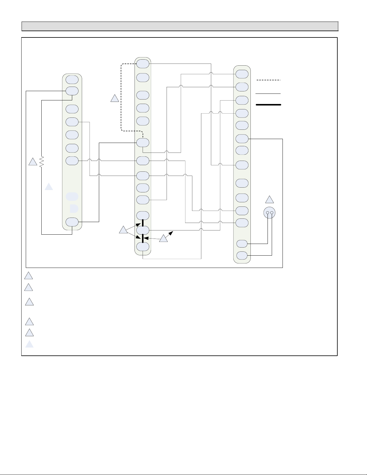
Field Control Wiring
One−Stage
Air Conditioner Control
W
L
Y2
Y1
O
DS
2
C
R
Air Handler Control
DS
O
5
L
H
DH
R
C
Y1
Y2
G
W3
W2
3
W1
ComfortSense[ 7000 Thermostats
Catalog # Y0349 or Y2081
R
On−board link
G
Low voltage thermostat
W2
W1
O
L
H
D
B
Y2
Y1
wiring
Flat metal jumper
1
C
4
T
T
1
Outdoor sensor for outdoor temperature display (Optional).
R connection required for outdoor unit with Control LSOM function. Resistor Kit (Cat# 47W97) is required when
2
using the ComfortSense 7000 (Y0349) with Control LSOM feature. Resistor kit not required when using
ComfortSense 7000 (Y2081).
Air Handler Control comes from factory with metal jumpers across W1, W2 and W3. For one−stage electric heat, do not remove
3
metal jumpers.
Air Handler Control comes from factory with metal jumpers across W1, W2 and W3. For two−stage electric heat, remove metal
4
jumper between W1 to W2 and connect thermostat wire between Air Handler Control W2 to thermostat W2.
5
Cut for Humiditrol Enhanced Dehumidification Accessory (EDA) applications.
Figure 9. ComfortSense® 7000 Series Thermostat
Air Hander/One−Stage Air Conditioner
Page 24
506510−01
Page 25
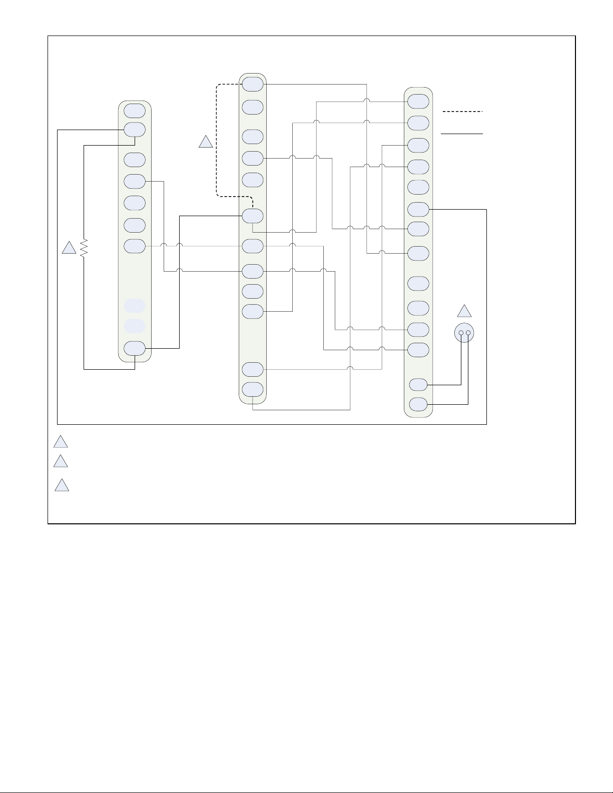
One−Stage
Air Conditioner Control
Furnace Control
DS
ComfortSense[ 7000 Thermostats
Catalog # Y0349 or Y2081
W
L
3
Y2
Y1
O
DS
2
C
O
L
H
DH
R
C
Y1
Y2
G
R
W2
W1
R
G
W2
W1
O
L
H
D
B
Y2
Y1
C
T
On−board link
Low voltage thermostat
wiring
1
T
Cut on−board link (W914) (clippable wire) from DS to R for dehumidification (Optional).
Outdoor sensor for outdoor temperature display (Optional).
1
R connection required for outdoor unit with Control LSOM function. Resistor Kit (Cat# 47W97) is required when
using the ComfortSense 7000 (Y0349) with Control LSOM feature. Resistor kit not required when using
2
ComfortSense 7000 (Y2081).
3
Cut for Humiditrol Enhanced Dehumidification Accessory (EDA) applications.
Figure 10. ComfortSense® 7000 Series Thermostat
Furnace/One−Stage Air Conditioner
Page 25
XC17 SERIES
Page 26

Servicing Units Delivered Void of Charge
If the outdoor unit is void of refrigerant, clean the system
using the procedure described below.
1. Leak check system using procedure outlined on Page
16.
2. Evacuate the system using procedure outlined on
Page 18.
3. Use nitrogen to break the vacuum and install a new
filter drier in the system.
4. Evacuate the system again using procedure outlined
on Page 18.
5. Weigh in refrigerant using procedure outlined in Figure
14.
6. Monitor the system to determine the amount of
moisture remaining in the oil. It may be necessary to
replace the filter drier several times to achieve the
required dryness level. If system dryness is not
verified, the compressor will fail in the future.
Unit Start−Up
1. Rotate fan to check for binding.
2. Inspect all factory− and field−installed wiring for loose
connections.
3. After evacuation is complete, open both the liquid and
vapor line service valves to release the refrigerant
charge contained in outdoor unit into the system.
4. Replace the stem caps and tighten to the value listed
in Table 1.
5. Check voltage supply at the disconnect switch. The
voltage must be within the range listed on the unit’s
nameplate. If not, do not start the equipment until you
have consulted with the power company and the
voltage condition has been corrected.
6. Set the thermostat for a cooling demand. Turn on
power to the indoor indoor unit and close the outdoor
unit disconnect switch to start the unit.
7. Recheck voltage while the unit is running. Power must
be within range shown on the nameplate.
8. Check system for sufficient refrigerant by using the
procedures listed under System Charge.
System Refrigerant
IMPORTANT
If unit is equipped with a crankcase heater, it should be
energized 24 hours before unit start−up to prevent
compressor damage as a result of slugging.
GAUGE SET
This section outlines procedures for:
1. Connecting gauge set for testing and charging;
2. Checking and adjusting indoor airflow;
3. Adding or removing refrigerant.
MANIFOLD GAUGE SET
LOW
HIGH
CONNECTIONS FOR TESTING AND CHARGING
SUCTION LINE
B
SERVICE PORT
CONNECTION
REFRIGERANT TANK
CHARGE IN
LIQUID PHASE
DIGITAL SCALE
TEMPERATURE
D
SENSOR
A Close manifold gauge set valves and connect the center hose to a cylinder of HFC−410A. Set for liquid phase charging.
B Connect the manifold gauge set’s low pressure side to the suction line service port.
C Connect the manifold gauge set’s high pressure side to the liquid line service port.
D Position temperature sensor on liquid line near liquid line service port.
A
TO LIQUID
LINE SERVICE
VALV E
C
TEMPERATURE SENSOR
(LIQUID LINE)
OUTDOOR UNIT
VAPOR LINE
SERVICE VALVE
LIQUID LINE
SERVICE VALVE
506510−01
Figure 11. Gauge Set Setup and Connections
Page 26
Page 27

ADDING OR REMOVING REFRIGERANT
This system uses HFC−410A refrigerant which operates at much higher pressures than HCFC−22. The pre−installed liquid
line filter drier is approved for use with HFC−410A only. Do not replace it with components designed for use with HCFC−22.
This unit is NOT approved for use with coils which use capillary tubes or fixed orifices as a refrigerant metering device.
Check airflow using the Delta−T (
DT) process using the illustration in Figure 12.
AIRFLOW
INDOOR COIL
Temperature of air
entering indoor
coil ºF
A
Wet−bulb ºF
DT
80 24 24 24 23 23 22 22 22 20 19 18 17 16 15
78 23 23 23 22 22 21 21 20 19 18 17 16 15 14
76 22 22 22 21 21 20 19 19 18 17 16 15 14 13
Dry−bulb
74 21 21 21 20 19 19 18 17 16 16 15 14 13 12
72 20 20 19 18 17 17 16 15 15 14 13 12 11 10
70 19 19 18 18 17 17 16 15 15 14 13 12 11 10
57 58 59 60 61 62 63 64 65 66 67 68 69 70
DRY
BULB
C
53º
T
19º
Drop
air flow
air flow
B
B
64º
All temperatures are expressed in ºF
INDOOR COIL
WET BULB
Use the following procedure to adjust for optimal air flow across the indoor coil:
1. Determine the desired DT Measure entering air temperature using dry bulb (A) and wet bulb (B). DT
is the intersecting value of A and B in the table (see triangle).
2. Find temperature drop across coil Measure the coil’s dry bulb entering and leaving air temperatures
(A and C). Temperature Drop Formula: (T
3. Determine if fan needs adjustment If the difference between the measured T
DT (T
–DT) is within +3º, no adjustment is needed. See example below:
Drop
) = A minus C.
Drop
and the desired
Drop
Assume DT = 15 and A temp. = 72º, these C temperatures would necessitate stated actions:
A
72º
DRY BULB
Cº T
53º 19 – 15 = 4 Increase the airflow
58º 14 – 15 = −1 (within +3º range) no change
62º 10 – 15 = −5 Decrease the airflow
– DT = ºF ACTION
Drop
Changing air flow affects all temperatures; recheck
temperatures to confirm that the temperature drop
and DT are within +3º.
4. Adjust the fan speed See indoor unit instructions to increase/decrease fan speed.
Figure 12. Checking Indoor Airflow over Evaporator Coil using Delta−T Chart
Page 27
XC17 SERIES
Page 28

Use WEIGH IN to initially charge a system when the outdoor unit is void of charge. To verify charge and add or
remove refrigerant use either
APPROACH or SUBCOOLING methods.
START: Determine the correct charge method:
WHEN TO CHARGE?
S Warm weather best
TXV
S Can charge in colder weather
CHARGE METHOD? Determine by:
S Outdoor ambient temperature
65ºF
(18.3ºC) and
Above
64ºF
(17.7ºC) and
Below
REQUIREMENTS:
S Sufficient heat load in structure
S Indoor temperature between 70-80ºF (21−26ºC)
S Manifold gauge set connected to unit
S Thermometers:
− to measure outdoor ambient temperature
APPROACH OR
SUBCOOLING
WEIGH-IN
− to measure liquid line temperature
− to measure suction line temperature
Figure 13. Determining Charge Method
WEIGH IN
CHARGING METHOD
CALCULATING SYSTEM CHARGE FOR OUTDOOR UNIT VOID OF CHARGE
64ºF (17.7ºC) and Below
If the system is void of refrigerant, first, locate and repair any leaks and then weigh in the refrigerant charge into the
unit. To calculate the total refrigerant charge:
Adjust amount. for variation
Amount specified on
nameplate
NOTE Insulate liquid line when it is routed through areas where the surrounding ambient temperature
could become higher than the temperature of the liquid line or when pressure drop is equal to or greater
than 20 psig.
NOTE The above nameplate is for illustration purposes only. Go to actual nameplate on outdoor unit for
charge information.
in line set length listed on
line set length table below.
Total charge
+
Refrigerant Charge per Line Set Length
Liquid Line
Set Diameter
3/8" (9.5 mm)
*If line length is greater than 15 ft. (4.6 m), add this amount. If
line length is less than 15 ft. (4.6 m), subtract this amount.
=
Ounces per 5 feet (g per 1.5 m)
adjust from 15 feet (4.6 m) line set*
3 ounce per 5’ (85 g per 1.5 m)
506510−01
Figure 14. Using HFC−410A Weigh In Method
Page 28
Page 29

1. Confirm proper airflow across coil using Figure 12.
APPROACH
TEST AND CHARGE METHOD
65ºF (18.3ºC) and Above
If refrigerant added or removed, retest to confirm that unit is properly
charged
If value is greater than shown (high approach), add refrigerant; if less
than shown (liquid temp too close to ambient temp, low approach),
remove refrigerant.
APPº (Approach) Values(F:+/−1.0° [C: +/−0.6°])*
Models
ºF (ºC)* −024 −030 −036 −042 −048 −060. . . . . .
Any 10 (5.6) 10 (5.6) 6 (3.3) 10 (5.6) 8 (4.4) 8 (4.4). . .
*Temperature of air entering outdoor coil
* These approach values are also listed on the unit charging sticker
580005−01 located on the access panel.
Figure 15. Using Approach Test and Charge Method
2. Compare unit pressures with Table 4, Normal Operating Pressures.
3. Use APPROACH to correctly charge unit or to verify the charge is
correct.
4. Set thermostat to call for heat (must have a cooling load between
70-80ºF (21−26ºC).
5. Connect gauge set.
6. When heat demand is satisfied, set thermostat to call for cooling.
7. Allow temperatures and pressures to stabilize.
8. Record outdoor ambient temperature:
AMBº =_________
9. Record line temperature:
LIQº = __________
10. Subtract to determine approach (APPº):
LIQº_____ − AMBº _____ = APPº_____
11. Compare results with table to the left.
SUBCOOLING
TEST AND CHARGE METHOD
65ºF (18.3ºC) and Above
BLOCK OUTDOOR COIL: [sometimes
necessary with lower temperatures]
Use cardboard or plastic sheet to restrict
the airflow through the outdoor coil to
achieve pressures from 325−375 psig
(2240−2585 kPa). Higher pressures are
needed to check charge. Block equal
CARDBOARD OR
PLASTIC SHEET
If refrigerant added or removed, verify charge using the approach
method
If value is greater than shown, remove refrigerant; if less than shown,
add refrigerant
SCº (Subcooling) Values (F:+/−1.0° [C: +/−0.6°])
ºF (ºC)* −024 −030 −036 −042 −048 −060. . . . . .
Any 4 (2.2) 4 (2.2) 7 (3.9) 5 (2.8) 6 (3.3) 6 (3.3). . .
*Temperature of air entering outdoor coil
* These subcooling values are also listed on the unit charging sticker
580005−01 located on the access panel.
sections of air intake panels and move
coverings sideways until the liquid
pressure is in the above noted ranges.
Models
1. Confirm proper airflow across coil using Figure 12.
2. Compare unit pressures with Table 4, Normal Operating Pressures.
3. Use SUBCOOLING to correctly charge unit or to verify the charge is
correct.
4. Set thermostat to call for heat (must have a cooling load between 70-80ºF
(21−26ºC)
5. Connect gauge set
6. Measure outdoor ambient temperature
7. When heat demand is satisfied, set thermostat to call for cooling
8. Allow temperatures and pressures to stabilize.
NOTE − If necessary, block outdoor coil to maintain 325 − 375 psig.
9. Record liquid line temperature:
LIQº = ______
10. Measure liquid line pressure and use the value to determine saturation
temperature (see Table 5):
SATº = ______
11. Subtract to determine subcooling (SCº):
SATº_____ − LIQº _____ = SCº _____
12. Compare results with table to the left.
Figure 16. Using Subcooling Test and Charge Method
Page 29
XC17 SERIES
Page 30

Operating and Temperature Pressures
Minor variations in these pressures may be expected due to differences in installations. Significant differences could mean
that the system is not properly charged or that a problem exists with some component in the system.
Table 4. Normal Operating Pressures (Liquid +10 and Suction +5 psig)*
Use this table to perform maintenance checks; it is not a procedure for charging the
IMPORTANT
Model −024 −030 −036 −042 −048 −060
°F (°C)** Liquid Suction Liquid Suction Liquid Suction Liquid Suction Liquid Suction Liquid Suction
65 (18.3) 234 139 236 134 226 134 232 137 232 132 236 131
70 (21.1) 249 140 251 135 245 135 249 139 249 133 254 132
75 (23.9) 268 141 271 138 266 137 270 140 268 134 273 133
80 (26.7) 289 142 291 139 287 138 291 141 288 135 294 135
85 (29.4) 310 142 312 140 310 139 314 142 311 136 317 136
90 (32.2) 334 144 335 142 333 140 338 143 333 137 340 137
95 (35.0) 358 145 358 142 358 141 363 144 357 138 364 139
100 (37.8) 383 146 383 143 383 143 389 145 380 139 389 140
105 (40.6) 408 147 409 144 410 144 419 147 406 140 416 142
110 (43.3) 436 148 436 145 437 145 447 148 433 142 444 143
115 (46.1) 465 150 467 147 464 146 480 149 462 143 475 145
* Typical pressures only, expressed in psig (liquid +/− 10 and vapor+/− 5 psig); indoor match up, indoor air quality, and indoor load will cause the pressures
to vary. These operating pressures are also listed on the unit charging sticker (580005−01) located on the access panel.
** Temperature of air entering outdoor coil.
system. Minor variations in these pressures may be due to differences in installations.
Significant deviations could mean that the system is not properly charged or that a
problem exists with some component in the system.
Table 5. HFC−410A Temperature (° Fahrenheit) Pressure (Psig)
°F Psig °F Psig °F Psig °F Psig °F Psig °F Psig °F Psig °F Psig
32 100.8 48 137.1 63 178.5 79 231.6 94 290.8 110 365.0
33 102.9 49 139.6 64 181.6 80 235.3 95 295.1 111 370.0 126 451.8 142 552.3
34 105.0 50 142.2 65 184.3 81 239.0 96 299.4 112 375.1 127 457.6 143 559.1
35 107.1 51 144.8 66 187.7 82 242.7 97 303.8 113 380.2 128 463.5 144 565.9
36 109.2 52 147.4 67 190.9 83 246.5 98 308.2 114 385.4 129 469.5 145 572.8
37 111.4 53 150.1 68 194.1 84 250.3 99 312.7 115 390.7 130 475.6 146 579.8
38 113.6 54 152.8 69 197.3 85 254.1 100 317.2 11 6 396.0 131 481.6 147 586.8
39 115.8 55 155.5 70 200.6 86 258.0 101 321.8 11 7 401.3 132 487.8 148 593.8
40 118.0 56 158.2 71 203.9 87 262.0 102 326.4 11 8 406.7 133 494.0 149 601.0
41 120.3 57 161.0 72 207.2 88 266.0 103 331.0 11 9 412.2 134 500.2 150 608.1
42 122.6 58 163.9 73 210.6 89 270.0 104 335.7 120 417.7 135 506.5 151 615.4
43 125.0 59 166.7 74 214.0 90 274.1 105 340.5 121 423.2 136 512.9 152 622.7
44 127.3 60 169.6 75 217.4 91 278.2 106 345.3 122 428.8 137 519.3 153 630.1
45 129.7 61 172.6 76 220.9 92 282.3 107 350.1 123 434.5 138 525.8 154 637.5
46 132.2 62 175.4 77 224.4 93 286.5 108 355.0 124 440.2 139 532.4 155 645.0
47 134.6 78 228.0 109 360.0 140 539.0
125 445.9
141 545.6
506510−01
Page 30
Page 31

System Operation
IMPORTANT
Some scroll compressor have internal vacuum protector
that will unload scrolls when suction pressure goes
below 20 psig. A hissing sound will be heard when the
compressor is running unloaded. Protector will reset
when low pressure in system is raised above 40 psig. DO
NOT REPLACE COMPRESSOR.
The Main Control provides the following system functions:
S Compressor anti−short−cycle delay.
S High and low pressure switches
S Am bient and Discharge Line Temperatures Monitoring
and Protection.
S Five strikes lockout safety feature for High/Low
Pressure Switches and High Discharge Line
Temperature. See Figures 19, 20 and 21 feature
function.
COMPRESSOR ANTI−SHORT CYCLE DELAY
The Main Control protects the compressor from:
S Short cycling (five minutes) when there is initial power
up
S Interruption in power to the unit
S High or low pressure switch or discharge line sensor
trips
S Delay after Y1 demand is removed.
The anti−short timer in the outdoor control is 5 minutes. To
override timer when active or inactive − place jumper on the
field test pins between 1 and 2 seconds.
Resetting Anti−Short Cycle Delay
The FIELD TEST pins (E33) on the Main Control can be
jumpered between 1 to 2 seconds to bypass delay.
HIGH AND LOW PRESSURE SWITCHES
The unit’s reset pressure switches LO PS (S4) and HI PS
(S87) are factory−wired into the Main Control on the LO−PS
and HI−PS terminals, there locations are illustrated on
Page 3. Sequence of operations for both pressure
switches are provided in Figures 19 and 20.
HIGH DISCHARGE LINE TEMPERATURE SENSOR
(RT28)
The high discharge line temperature sensor location is
illustrated on Page 3. This sensor’s sequence of
operations is provided in Figure 21.
High Discharge Line Sensor Open/Shorted Event
Condition
Discharge sensor open / short fault is ignored during initial
90−seconds of compressor run time. After that, if discharge
temperature sensor is detected open or short, the control
will de−energize all the outputs and anti−short cycle timer is
started. Discharge sensor faulty alert LED code will be
displayed.
OUTDOOR AMBIENT TEMPERATURE (RT13)
If the outdoor ambient temperature sensor detected a
open, or out of range −40ºF to +140ºF (−40ºC to 60ºC) then
LED alert codes are displayed, however cooling operation
will continue. See Table 9 for LED alert codes for the
ambient sensor. Location of outdoor ambient temperature
sensor is illustrated on Page 3.
COIL TEMPERATURE SENSOR
This model does not use a coil temperature sensor. The
cable assembly attached to the Main Control’s E30
connection has a 10K resister installed between pins 5 and
6 as illustrated in Figure 17. No alerts or alarms would be
generated if resistor is damage.
Ambient Air
Temperature Sensor
High Discharge Line
Temperature Sensor
Figure 17. 10k Resistor Location
TESTING AMBIENT AND HIGH DISCHARGE LINE
TEMPERATURE SENSORS
Sensors connect through a field-replaceable harness
assembly that plugs directly into the Main Control.
Through these sensors, the Main Control can monitor
outdoor ambient and discharge line temperature fault
conditions. As the detected temperature changes, the
resistance across the sensor changes. Figures 6 and 7
lists how the resistance varies as the temperature changes
for both type of sensors. Sensor resistance values can be
checked by ohming across pins shown in Table 8.
When a sensor indicates a resistance value that is not
within the range as listed in Table 8, then the following
condition may be present:
10K resistor
S Sensor detects an out−of−range outdoor ambient air
temperature condition and will display LED alert code
on the Main Control.
S The sensor is operating normally when the ambient air
temperature at the sensor is below or above the Main
Control’s expected ohm values. The Main Control will
indicate the sensor as faulty, however under this
scenario, the sensor is not actually faulty.
S Once the outdoor ambient air temperature has
returned to within the sensor’s normal operating
range, the LED alert code will automatically stop.
Page 31
XC17 SERIES
Page 32
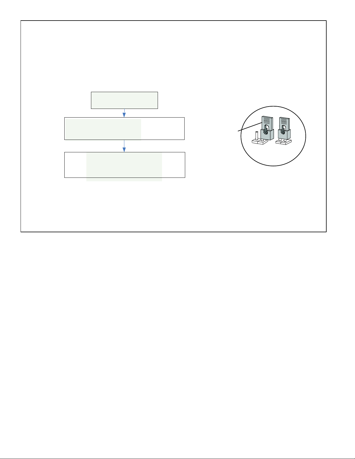
TEST PINS FUNCTION
Placing the JUMPER ON the field test pins (E33) (see Page 22 for location of TEST pins) allows the technician to
S Clear compressor anti−short cycle delay.
S Clear five−strike fault lockouts High / Low pressure switches and High Discharge Temperature Sensor.
Y1 Active
Place a JUMPER ON1 the TEST pins for longer than one
second2. Then remove jumper and place in JUMPER
OFF position.
FACTORY DEFAULT
JUMPER SETTING
Clears any short cycle lockout and five strike fault lockout
function, if applicable. No other functions will be executed
and unit will continue in the mode it was operating.
JUMPER
OFF
JUMPER
ON
NOTES:
1 Placing a JUMPER ON the TEST pins will not bring the unit out of inactive mode. The only way manually
activate the outdoor unit from an inactive mode is to cycle the 24VAC power to the outdoor unit’s Main Control.
2 If the jumper remains on the TEST pins for longer than five seconds, the Main Control will ignore the
JUMPER ON TEST pins and revert to normal operation.
Figure 18. Clearing Anti−Short Cycle Delay and Five−Strike Fault Lockouts
506510−01
Page 32
Page 33
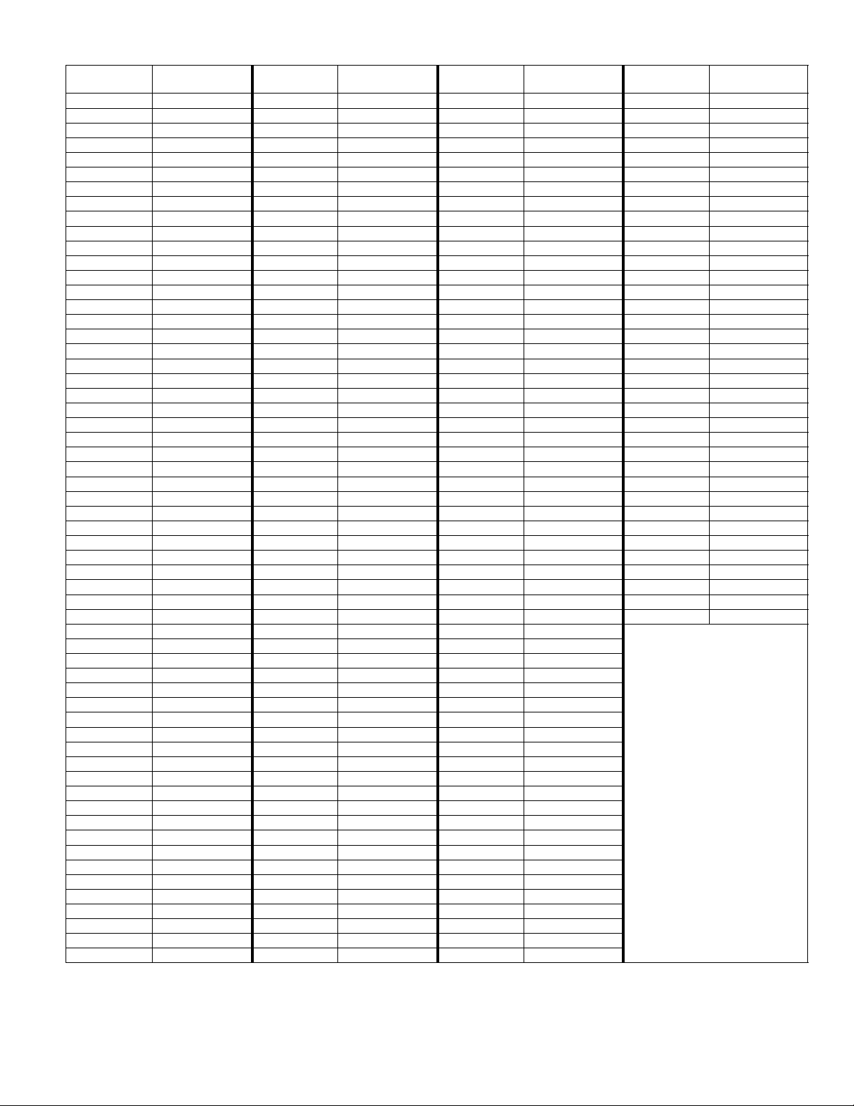
Table 6. Ambient Sensor Temperature / Resistance Range
Degrees
Fahrenheit
136.3 2680 56.8 16657 21.6 44154 −11.3 123152
133.1 2859 56.0 16973 21.0 44851 −11.9 125787
130.1 3040 55.3 17293 20.5 45560 −12.6 128508
127.3 3223 54.6 17616 20.0 46281 −13.2 131320
124.7 3407 53.9 17942 19.4 47014 −13.9 134227
122.1 3592 53.2 18273 18.9 47759 −14.5 137234
119.7 3779 52.5 18607 18.4 48517 −15.2 140347
117.5 3968 51.9 18945 17.8 49289 −15.9 143571
115.3 4159 51.2 19287 17.3 50074 −16.5 146913
113.2 4351 50.5 19633 16.8 50873 −17.2 150378
111.2 4544 49.9 19982 16.3 51686 −17.9 153974
109.3 4740 49.2 20336 15.7 52514 −18.6 157708
107.4 4937 48.5 20695 15.2 53356 −19.3 161588
105.6 5136 47.9 21057 14.7 54215 −20.1 165624
103.9 5336 47.3 21424 14.1 55089 −20.8 169824
102.3 5539 46.6 21795 13.6 55979 −21.5 174200
100.6 5743 46.0 22171 13.1 56887 −22.3 178762
99.1 5949 45.4 22551 12.5 57811 −23.0 183522
97.6 6157 44.7 22936 12.0 58754 −23.8 188493
96.1 6367 44.1 23326 11.5 59715 −24.6 193691
94.7 6578 43.5 23720 11.0 60694 −25.4 199130
93.3 6792 42.9 24120 10.4 61693 −26.2 204829
92.0 7007 42.3 24525 9.9 62712 −27.0 210805
90.6 7225 41.7 24934 9.3 63752 −27.8 217080
89.4 7444 41.1 25349 8.8 64812 −28.7 223677
88.1 7666 40.5 25769 8.3 65895 −29.5 230621
86.9 7890 39.9 26195 7.7 67000 −30.4 237941
85.7 8115 39.3 26626 7.2 68128 −31.3 245667
84.5 8343 38.7 27063 6.7 69281 −32.2 253834
83.4 8573 38.1 27505 6.1 70458 −33.2 262482
82.3 8806 37.5 27954 5.6 71661 −34.1 271655
81.2 9040 37.0 28408 5.0 72890 −35.1 281400
80.1 9277 36.4 28868 4.5 74147 −36.1 291774
79.0 9516 35.8 29335 3.9 75431 −37.1 302840
78.0 9757 35.2 29808 3.4 76745 −38.2 314669
77.0 10001 34.7 30288 2.8 78090 −39.2 327343
76.0 10247 34.1 30774 2.3 79465
75.0 10496 33.5 31267 1.7 80873
74.1 10747 33.0 31766 1.2 82314
73.1 11000 32.4 32273 0.6 83790
72.2 11256 31.9 32787 0.0 85302
71.3 11515 31.3 33309 −0.5 86852
70.4 11776 30.7 33837 −1.1 88440
69.5 12040 30.2 34374 −1.7 90068
68.6 12306 29.6 34918 −2.2 91738
67.7 12575 29.1 35471 −2.8 93452
66.9 12847 28.6 36031 −3.4 95211
66.0 13122 28.0 36600 −4.0 97016
65.2 13400 27.5 37177 −4.6 98870
64.4 13681 26.9 37764 −5.2 100775
63.6 13964 26.4 38359 −5.7 102733
62.8 14251 25.8 38963 −6.3 104746
62.0 14540 25.3 39577 −6.9 106817
61.2 14833 24.8 40200 −7.5 108948
60.5 15129 24.2 40833 −8.2 1111 41
59.7 15428 23.7 41476 −8.8 113400
59.0 15730 23.2 42130 −9.4 115727
58.2 16036 22.6 42794 −10.0 118126
57.5 16345 22.1 43468 −10.6 120600
Resistance
Degrees
Fahrenheit
Resistance
Degrees
Fahrenheit
Resistance
Degrees
Fahrenheit
Resistance
Page 33
XC17 SERIES
Page 34
Table 7. High Discharge Sensor Temperature / Resistance Range
Degrees
Fahrenheit
303.1 183 186.1 1052 136.8 2656 94.5 6613
298.1 195 185.0 1072 136.0 2698 93.6 6739
293.4 207 183.9 1093 135.2 2740 92.8 6869
289.0 220 182.8 1114 134.5 2783 92.0 7002
284.8 232 181.8 1135 133.7 2827 91.2 7139
280.9 245 180.7 1157 132.9 2872 90.3 7281
277.1 258 179.6 1179 132.2 2917 89.5 7426
273.6 270 178.6 1201 131.4 2963 88.6 7575
270.2 283 177.6 1223 130.6 3010 87.8 7729
267.0 297 176.6 1245 129.9 3057 86.9 7888
263.9 310 175.5 1268 129.1 3105 86.0 8051
260.9 323 174.6 1291 128.4 3154 85.2 8220
258.1 336 173.6 1315 127.6 3204 84.3 8394
255.3 350 172.6 1338 126.8 3255 83.4 8574
252.7 364 171.6 1362 126.1 3307 82.5 8759
250.1 378 170.6 1386 125.3 3359 81.6 8951
247.7 391 169.7 1411 124.6 3413 80.7 9149
245.3 405 168.7 1435 123.8 3467 79.8 9354
243.0 420 167.8 1460 123.1 3523 78.8 9566
240.8 434 166.9 1486 122.3 3579 77.9 9786
238.6 448 165.9 1511 121.6 3637 76.9 10013
236.5 463 165.0 1537 120.8 3695 76.0 10250
234.4 478 164.1 1563 120.1 3755 75.0 10495
232.4 492 163.2 1590 119.3 3816 74.1 10749
230.5 507 162.3 1617 118.5 3877 73.1 11014
228.6 523 161.4 1644 117.8 3940 72.1 11289
226.7 538 160.5 1672 117.0 4005 71.1 11575
224.9 553 159.7 1699 116.3 4070 70.0 11873
223.2 569 158.8 1728 115.5 4137 69.0 12184
221.5 584 157.9 1756 114.8 4205 68.0 12509
219.8 600 157.1 1785 114.0 4274 66.9 12848
218.1 616 156.2 1815 113.2 4345 65.8 13202
216.5 632 155.3 1845 112.5 4418 64.7 13573
214.9 649 154.5 1875 111.7 4491 63.6 13961
213.4 665 153.6 1905 111.0 4567 62.5 14368
211.9 682 152.8 1936 110.2 4644 61.3 14796
210.4 698 152.0 1968 109.4 4722 60.2 15246
208.9 715 151.1 1999 108.7 4802 59.0 15719
207.5 732 150.3 2032 107.9 4884 57.8 16218
206.0 750 149.5 2064 107.1 4968 56.6 16744
204.6 767 148.7 2098 106.4 5054 55.3 17301
203.3 785 147.9 2131 105.6 5141 54.0 17891
201.9 803 147.1 2165 104.8 5231 52.7 18516
200.6 821 146.2 2200 104.0 5323 51.4 19180
199.3 839 145.4 2235 103.3 5416 50.0 19887
198.0 857 144.6 2270 102.5 5512 48.6 20641
196.8 876 143.8 2306 101.7 5610 47.2 21448
195.5 894 143.0 2343 100.9 5711 45.7 22311
194.3 913 142.3 2380 100.1 5814
193.1 932 141.5 2418 99.3 5920
191.9 952 140.7 2456 98.5 6028
190.7 971 139.9 2495 97.7 6139
189.5 991 139.1 2534 96.9 6253
188.4 1011 138.3 2574 96.1 6370
187.2 1031 137.6 2615 95.3 6489
Resistance
Degrees
Fahrenheit
Resistance
Degrees
Fahrenheit
Resistance
Degrees
Fahrenheit
Resistance
506510−01
Page 34
Page 35
Table 8. Sensor Temperature / Resistance Range
Temperature
Sensor
Outdoor
(Ambient)
Discharge −35ºF to 310ºF
Note: Sensor resistance decreases as sensed temperature increases
(see Figures 6 and 7).
Range °F (°C)
−40ºF to 140ºF
(−40ºC to 60ºC)
(−37ºC to 154ºC)
Resistance values
range (ohms)
280,000 to 3750 3 and 4
41,000 to 103 1 and 2
Pins/Wire
Color
(Black)
(Yellow)
Main Control LED Alert Codes
Main Control LED alert codes (simply referred to as LED
alert codes) are located on the Main Control and marked
with the following identification.
DS11 AND DS14 LED SYSTEM AND ALERT CODES
DS11 (Green) and DS14 (Red) LEDs indicate diagnostics
conditions that are listed in Table 9.
These LEDs display fault conditions in system cooling
capacity, dehumidification mode, anti−short cycle lockout,
high and low pressures, discharge line temperature,
outdoor temperature, and discharge sensor failures.
DS15 AND DS13 LED COMPRESSOR ALERT CODES
DS15 (Yellow) and DS13 (Red) LEDs indicate diagnostics
conditions that are listed in Table 9.
These LEDs display the most common fault conditions in
the system. When an abnormal condition is detected, this
function communicates the specific condition through
LEDs. The diagnostic function is capable of detecting both
mechanical and electrical system abnormal conditions.
RESETTING LED ALERT CODES
LED alert codes can be reset either manually or
automatically:
1. Manual Reset
Manual reset can be achieve by one of the following
methods:
S Disconnect R wire from the Main Control’s R
terminal.
S Turning main power OFF and then ON at the unit’s
disconnect switch.
After power up, existing code will display for 60
seconds and then clear.
2. Automatic Reset
After an alert is detected, the Main Control continues
to monitor the unit’s system and compressor
operations. When/if conditions return to normal, the
alert code is turned off automatically.
IMPORTANT
LED alert codes do not provide safety protection. The is a monitoring function only and cannot control or shut down other
devices.
Table 9. System LED Alert Codes
Outdoor Main Control
Alternating FAST Flash
LEDs
DS11
Green
OFF OFF Power problem
Simultaneous SLOW
Alternating SLOW
Simultaneous FAST
DS14 Red
Flash
Flash
Flash
Condition Possible Cause(s) Solution
Normal operation
5−minute
anti−short cycle
delay
Ambient Sensor
Problem
Coil Sensor
Problem
SYSTEM STATUS
No power (24V) to control
terminals R and C or
control failure.
Unit operating normally or
in standby mode.
Initial power up, safety trip,
end of room thermostat
demand.
Sensor being detected open or shorted or out of temperature range. control will revert to time/temperature defrost operation. (System will still heat or cool).
This model does not utilize a coil sensor, however this alert indicates either an open or shorted circuit.
See if 10K resistor is not damage or missing. Resistor is located in the sensor harness assembly,
brown lead.
1
Check control transformer power (24V).
2
If power is available to control and LED(s) do not light, replace control.
Indicates that control has internal component failure. Cycle 24 volt power to control. If code does not clear, replace control.
None required (Jumper FIELD TEST pins to override)
ON ON
Main Control
Board Failure
Indicates that control has internal component failure. Cycle 24 volt power to control. If code does not
clear, replace control.
Page 35
XC17 SERIES
Page 36
Outdoor Main Control
LEDs
DS11
DS11
Green
Green
DS14 Red
DS14 Red
1 Fast
OFF
Flash then
Pause
Heating Low
Capacity
SolutionPossible Cause(s)Condition
SolutionPossible Cause(s)Condition
SolutionPossible Cause(s)Condition
OFF
ON
1 Fast
Flash then
Pause
2 Fast
Flash then
Pause
2 Fast
Flash then
Pause
OFF
OFF ON
SLOW
Flash
ON OFF
2 Fast
Flash then
Pause
2 Fast
Flash then
Pause
OFF
OFF
ON
SLOW
Flash
OFF
Heating High
Capacity
Defrost
Cooling Low
Capacity
Cooling High
Capacity
Dehumidification
Mode
Low Pressure
Fault
Low Pressure
Switch Lockout
High Pressure
Fault
High Pressure
Discharge Sensor
Lockout
These are codes that show status of operation whether in low stage or high stage, heating or cooling,
defrost or in the EDA mode.
ALERT STATUS
1
Restricted air flow over
indoor or outdoor coil.
2
Improper refrigerant
charge in system.
3
Improper metering device installed or incorrect
operation of metering device.
4
Incorrect or improper
sensor location or con-
1
Remove any blockages or restrictions from coils and/or fans. Check
indoor and outdoor fan motor for proper current draws.
2
Check system charge using approach and subcooling temperatures.
3
Check system operating pressures and compare to unit charging
charts.
4
Make sure all pressure switches and sensors have secure connections to system to prevent refrigerant leaks or errors in pressure and
temperature measurements.
nection to system.
SLOW
Flash
FAST
Flash
ON
ON
OFF Fast Flash
Fast simultaneous
flashing of DS11, DS13,
DS14 and DS15
Discharge Line
Temperature Fault
Discharge Line
Temperature
Lockout
Discharge Sensor
Fault
This code detects high discharge temperatures. If the discharge line temperature exceeds a temperature
of 279ºF (137ºC) during compressor operation, the control will de−energize the compressor contactor
output (and the defrost output if active). The compressor will remain off until the discharge temperature
has dropped below 225ºF (107ºC). See Figure 21 for further details concerning lockouts and reset
procedures.
The control detects open or short sensor or out of temperature sensor range. This fault is detected by
allowing the unit to run for 90 seconds before checking sensor resistance. If the sensor resistance is
not within range after 90 seconds, the control will raise the alarm.
OEM Mode Factory Test Mode.
506510−01
Page 36
Page 37

Outdoor Main
Control LEDs
DS15
Yellow
DS13
Red
OFF ON
1 Flashes
then
OFF Long run time.
Pause
2 Flashes
then
OFF
Pause
3 Flashes
then
OFF Short Cycling
Pause
4 Flashes
then
OFF Locked Rotor
Pause.
Condition
Compressor
Internal
Overload Trip
System
Pressure Trip
Table 10. Compressor LED Alert Codes
Possible
Cause(s)
Thermostat
demand signal Y1
is present, but
compressor not
running
Compressor is
running extremely
long run cycles.
Indicates the
compressor
protector is open
or missing supply
power to the
compressor.
Compressor is
running less than
three minutes.
Compressor has
a locked out due
to run capacitor
short, bearings
are seized, excessive liquid refrigerant.
Solution
1
Compressor protector is open.
S Check for high head pressure
S Check compressor supply voltage
2
Outdoor unit power disconnect is open.
3
Compressor circuit breaker or fuse(s) is open.
4
Broken wire or connector is not making contact.
5
Low or high pressure switch open if present in the
system.
6
Compressor contactor has failed to close.
1
Low refrigerant charge.
2
Evaporator blower is not running.
S Check blower relay coil and contacts
S Check blower motor capacitor
S Check blower motor for failure or blockage
S Check evaporator blower wiring and connectors
S Check indoor blower control
S Check thermostat wiring for open circuit
3
Evaporator coil is frozen.
S Check for low suction pressure
S Check for excessively low thermostat setting
S Check evaporator airflow (coil blockages or return
air filter)
S Check ductwork or registers for blockage.
4
Faulty metering device.
S Check TXV bulb installation (size, location and
contact)
S Check if TXV/fixed orifice is stuck closed or de-
fective
5
Condenser coil is dirty
6
Liquid line restriction (filter drier blocked if present)
7
Thermostat is malfunctioning
.
S Check thermostat sub−base or wiring for short cir-
cuit
S Check thermostat installation (location and level)
1
High head pressure.
S Check high pressure switch if present in system
S Check if system is overcharged with refrigerant
S Check for non−condensable in system
2
Condenser coil poor air circulation (dirty, blocked,
damaged).
3
Condenser fan is not running.
S Check fan capacitor
S Check fan wiring and connectors
S Check fan motor for failure or blockage
4
Return air duct has substantial leakage.
1
Thermostat demand signal is intermittent.
2
Time delay relay or Main Control is defective.
3
If high pressure switch is present, see Flash Code 2
information.
1
Run capacitor has failed.
2
Low line voltage (contact utility if voltage at disconnect
is low).
S Check wiring connections
3
Excessive liquid refrigerant in the compressor.
4
Compressor bearings are seized.
Clearing Status
Clears the error after current
is sensed in the run and
start winding for two
seconds, service removed
or power reset.
Clears the error after 30
consecutive normal run
cycles, or after power reset.
.
.
Clears after four
consecutive normal
compressor run cycles, or
after power reset.
Clears after four
consecutive normal
compressor run cycles, or
after power reset.
Clears after power reset or
four normal compressor
cycles.
Page 37
XC17 SERIES
Page 38

Outdoor Main
Control LEDs
DS15
Yellow
5 Flashes
then
Pause
6 Flashes
then
Pause
7 Flashes
then
Pause
Condition
DS13
Condition
Red
OFF Open Circuit
OFF
OFF
Open Start
Circuit
Open Run
Circuit
Possible
Possible
Cause(s)
Cause(s)
Compressor has
an open circuit
due to power disconnection, fuse
is open or other
similar conditions.
Current not
sensed by Start
transformer.
Current not
sensed by run
transformer.
Solution
Solution
1
Outdoor unit power disconnect is open.
2
Unit circuit breaker or fuse(s) is open.
3
Unit contactor has failed to close.
S Check compressor contactor wiring and con-
nectors
S Check for compressor contactor failure (burned,
pitted or open)
S Check wiring and connectors between supply and
compressor
S Check for low pilot voltage at compressor con-
tactor coil
4
High pressure switch is open and requires manual
reset.
5
Open circuit in compressor supply wiring or connections.
6
Unusually long compressor protector reset time due
to extreme ambient temperature.
7
Compressor windings are damaged.
S Check compressor motor winding resistance
1
Run capacitor has failed.
2
Open circuit in compressor start wiring or connections.
S Check wiring and connectors between supply and
the compressor S terminal
3
Compressor start winding is damaged.
S Check compressor motor winding resistance
1
Open circuit in compressor start wiring or connections.
S Check wiring and connectors between supply and
the compressor R terminal
2
Compressor start winding is damaged.
S Check compressor motor winding resistance
Clearing Status
Clearing Status
Clears after one normal
compressor run cycle or
power reset.
Clears when amperage is
detected in RUN and
START sensors, or after
power reset.
Clears when amperage is
detected in RUN and
START sensors, or after
power reset.
8 Flashes
then
OFF
Pause
9 Flashes
then
OFF
Pause
Fast simultaneous
flashing of DS11,
DS13, DS14 and
DS15
Welded
Contactor
Secondary
Low Voltage
Compressor
always runs
24VAC is below
18VAC.
OEM Mode Factory Test Mode.
1
Compressor contactor failed to open.
2
Thermostat demand signal not connected to module.
1
Control circuit transformer is overloaded.
2
Low line voltage (contact utility if voltage at disconnect
is low).
S Check wiring connections
Clears after one normal
compressor run cycle or
after power reset.
Clears after voltage is higher
than 20VAC for two
seconds, or after power
reset.
506510−01
Page 38
Page 39
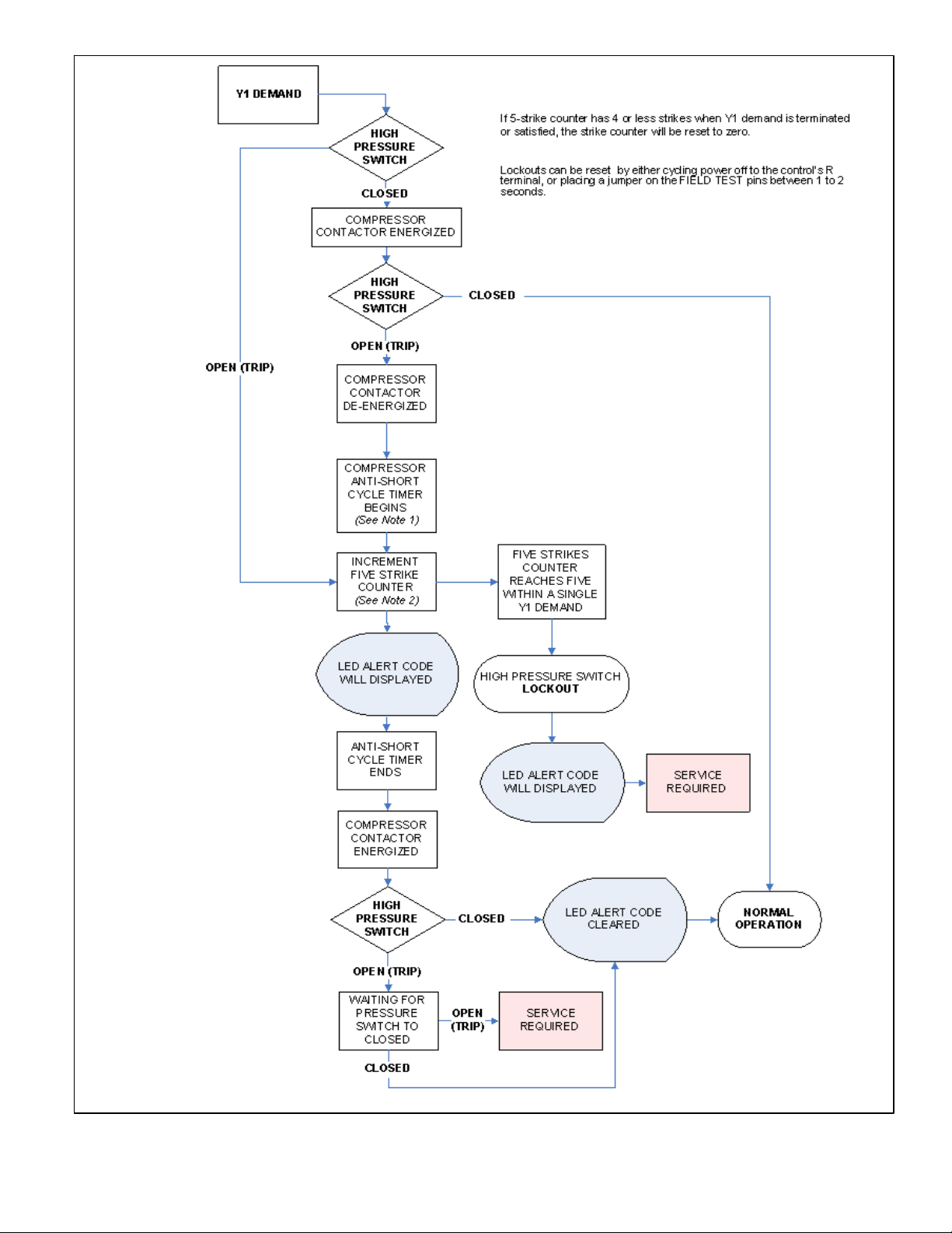
Figure 19. High Pressure Switch Operation
Page 39
XC17 SERIES
Page 40
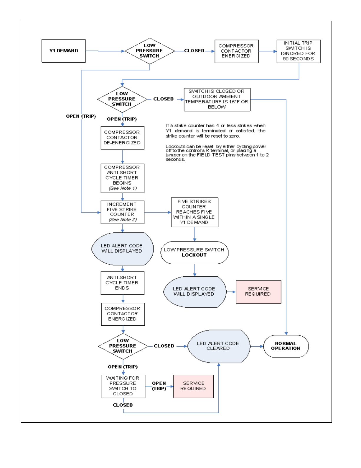
506510−01
Figure 20. Low Pressure Switch Operation
Page 40
Page 41
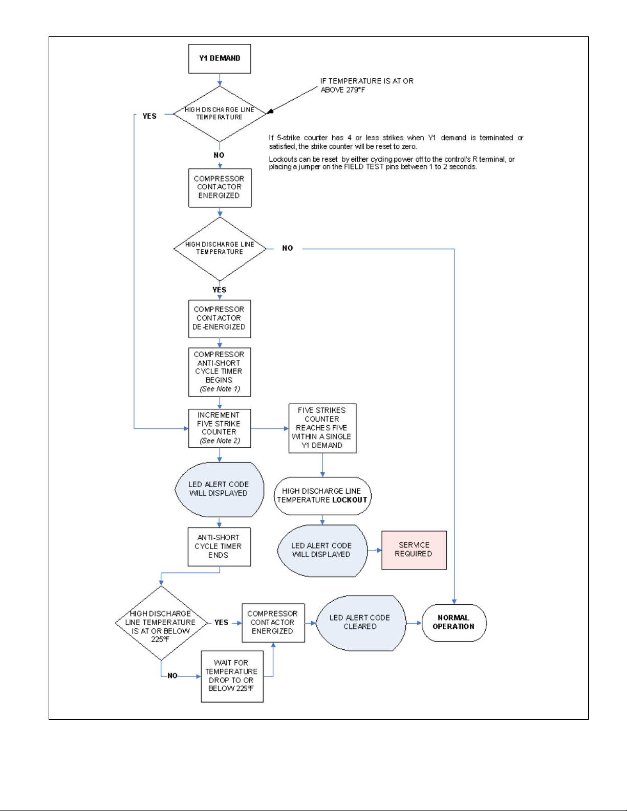
Figure 21. High Discharge Temperature Sensor Operation
Page 41
XC17 SERIES
Page 42

Maintenance
WARNING
Electric shock hazard. Can cause injury
or death. Before attempting to perform
any service or maintenance, turn the
electrical power to unit OFF at disconnect
switch(es). Unit may have multiple power
supplies.
VERIFYING LED STATUS CODES
During start up, the fan motor control LED will
display any error conditions. If error conditions
exist then no other codes will display. If no error
conditions are present, then the stage status and
and RPM indicator are displayed. Fan motor speeds
are not adjustable for a single stage outdoor unit (see
table 11).
WARNING
Improper installation, adjustment, alteration, service or
maintenance can cause personal injury, loss of life, or
damage to property.
Installation and service must be performed by a licensed
professional installer (or equivalent) or a service agency.
DEALER
Verifying Fan Motor Operation
FAN MOTOR CONTROL AND START UP
This motor control is used in controlling motors which
employ a Pulse Width Modulation (PWM) controller. A
PWM signal will run the fan motor at a revolutions per
minute (RPM) that corresponds to a specific PWM signal.
VERIFYING JUMPER SETTINGS (J2)
The unit is shipped from the factory with the default motor
RPM setting required for the specific model size. Use table
11 for one−stage to verify that the jumpers are set correctly
for the specific size unit.
Table 11. One Stage Motor Control RPM Jumper Settings, LED RPM Indicator and P2 DC Voltage Outputs
CFM Profile Pin Select
Model LED Code*
4 3 2 1 RPM (J2) DC Volt
VERIFYING CORRECT DC OUTPUT VOLTAGE (J2)
The following three methods can be used to determine
whether the fan motor is operating at the correct RPMs
based on unit size.
1. Use the information provided in tables 11 to verify that
all four jumper terminals are set correctly for the
specific size unit.
2. Verify LED RPM indicator is displaying the correct
flash sequence for the applicable size unit (see Table
11).
3. Test DC voltage output on the Motor Control’s J2
terminals (see Figure 23) while under full load and
verify the voltage read to the voltage listed in Table 11
for the applicable size unit.
4. If no voltage is detected at the J2 terminals, verify
there is a Y1 demand at the thermostat and 24V
present at the Fan Control’s EXT PWR/R terminal
during that Y1 demand (see Figure 24).
5. If 24V is present at the Fan Control EXT PWR/R
terminal during a Y1 thermostat demand, and no
voltage is present at the J2 terminals, then Fan Control
should be replaced.
ECM1/Y1
(One Stage and EDA Operation)
XP/XC17−048, −060 9 OFF OFF OFF ON 675 21.6
XP/XC17−036, −042 8 OFF OFF ON ON 600 19.2
XP/XC17−030 6 OFF ON ON OFF 450 14.3
XP/XC17−024 5 OFF ON ON ON 400 12.7
* LED Code indicates Fan Control LED flash sequence. For example, LED Code 9 indicates 9 slow flashes and pause.
Page 42
506510−01
Page 43

LED CODES AND SEQUENCE OF OPERATIONS
During start up, the LED will first display any error conditions (see table 12) if present. If no errors are detected then the LED
code indicating one or two stage operation will display then a long pause. The RPM indicator is displayed next. After the RPM
indicator is displayed there is a short pause and the sequence repeats if a thermostat demand is still present. See Figure 22
for LED sequence of operations. See table 13 for description of flash and pause durations.
Table 12. Error/Fault LED Codes
Unit Status Motor Control LED Possible Cause
Mismatched RPM Fast Flash with no pause
Internal feedback, PWM does not match target.
CRC Failure Constant ON. Microcontroller CRC failure.
Table 13. Fan Motor Board Unit LED Codes
Unit Status Unit Status Motor Control LED
One Stage Operation Low Stage ECM1/Y1 ONLY One slow flash, then short pause.
RPM Indicator
NOTE There is a long pause between stage
operation and RPM indicator. See Tables 1 and 2
for LED RPM indicator.
Flash Flash = Three flashes per second.
Slow Flash = One flash per second.
Short Pause = Two seconds of OFF time.
Long Pause = Five seconds of OFF time.
RPM Indicator
Appropriate number of flashes (See Tables
11 and 2).
YES
DEMAND
BEGINS
MISMATCHED
RPM
CRC FAILURE
SINGLE STAGE
OR EDA
OPERATION
NO
DEMAND
ENDED
FAN MOTOR PWM CONTROL (ONE STAGE AND
SINGLE FAN SPEED)
DEFAULT FAN
MOTOR SPEED
ECM1/Y1
ONLY OR
ECM2/Y2
ONLY
MOTOR SPEED
USED
DEFAULT FAN
USED
FAN MOTOR
RPM SET PER
JUMPER
SETTINGS
LED CONTINUOUS FAST
FLASH
LED CONSTANT ON
REPLACE FAN MOTOR
CONTROL BOARD
REPLACE FAN MOTOR
CONTROL BOARD
STAGE LED INDICATOR: ONE
SLOW FLASH AND ONE
SHORT PAUSE FOR SINGLE
STAGE OR EDA OPERATION
LED RPM INDICATOR:
EXAMPLE: (2−TON
UNIT) – 5 SLOW
FLASHES AND ONE
LONG PAUSE
Figure 22. Single Stage LED Sequence of Operation
Page 43
XC17 SERIES
Page 44

FAN MOTOR CONTROL
PULSE−WIDTH MODULATION (PWM)
CFM Profile Pin Select
MAIN CONTROL
CONTROL PANEL
VERIFY DC VOLTAGE OUTPUT USING FAN PWM OUT AND
COM TERMINALS. SEE TABLE 11 FOR OPTIMAL DC
VOLTAGE BASED ON CFM PROFILE USED.
J2
COM
COM
PARK
J2
JUMPER
OFF
JUMPER
ON
LED
GREEN
FAN PWM OUT
FAN PWM OUT
RED
RED
YELLOW BLACK
YELLOW
YELLOW
BLACK
BLUE
YELLOW
YELLOW
BLACK
PWM FAN
CONTROL
SEE TABLE 11 FOR CFM PROFILE SELECTION OPTIONS.
Figure 23. Fan Control, Wiring, Jumper Settings, Testing and LED Location
GREEN
RED
RED
BLACK
BROWN
506510−01
Page 44
Page 45

FAN MOTOR CONTROL
PULSE−WIDTH MODULATION (PWM)
MAIN CONTROL
GREEN
RED
RED
YELLOW BLACK
CONTROL PANEL
BLACK WIRE
TO MAIN CONTROL
YELLOW WIRE
YELLOW
YELLOW
BLACK
COM
EXT PWR/R
GREEN
RED
RED
BLACK
BROWN
BLUE
YELLOW
BLACK
YELLOW
PWM FAN
CONTROL
SEE TABLE 11 FOR CFM PROFILE SELECTION OPTIONS.
Figure 24. Testing for External Power to Fan Control
Page 45
XC17 SERIES
Page 46

FAN MOTOR TEST PROCEDURE
A simple test can be used to test the fan motor operation. A fully charged 9V battery will be required for this procedure.
FAN MOTOR TEST
This is a test that will verify that the motor does operate.
1. Verify main (240 volt) power if OFF to unit.
2. Remove both wires (brown and black) from the J2 terminal on the fan motor
control.
3. Room thermostat should be in OFF position (Unit in idle mode − no heating or
cooling demands)
4. Turn main power (240 volt) ON to unit.
5. Connect 9 Volt batter to outdoor fan motor plugs as noted in picture below..
6. Outdoor fan motor should run at a reduced fan speed.
7. If Outdoor fan motor does not run, then replace fan motor assembly.
REMOVE BOTH LEADS
FROM J2 TERMINALS
BLACK LEAD
BROWN LEAD
J2
COM
PARK
FAN PWM OUT
FAN MOTOR CONTROL
J2
BLACK LEAD
CONNECT FAN MOTOR BLACK
COMMON WIRE TO 9V BATTERY
NEGATIVE TERMINAL
NEGATIVE TERMINAL POSITIVE TERMINAL
BLACK LEAD
BROWN LEAD
BROWN LEAD
CONNECT FAN MOTOR WIRE TO
9V BATTERY POSITIVE TERMINAL
V
506510−01
FULLY CHARGED 9V BATTERY
Figure 25. Fan Motor Test
Page 46
Page 47

FAN MOTOR SURGE PROTECTION
Surge Protector (Metal Oxide Varistor − MOV) − A part
designed to protect electrical devices from voltage spikes
that are 3 to 4 times the normal circuit voltage (See Figure
26 for illustration of component).
An MOV works as follows: It is essentially a batch of
metallic−oxide grains separated by insulating layers.
Repeated voltage surges break down the insulating layers,
lowering the overall resistance and eventually causing the
device to draw too much current and trip whatever
over−current protection is inherent in the system)
MOV Check: They are supposed to be located beyond the
line fuse (though possibly not always). In this case, where
the line fuse blows or circuit breaker trips but there is no
visible damage to the MOV(s), the simplest test may be to
just temporarily remove the MOV(s) and see if the problem
goes away.
See Figure 1 for location of the Surge Protections device
which is located in the unit control box area.
NOTE It may be necessary to flush the outdoor coil
more frequently if it is exposed to substances which are
corrosive or which block airflow across the coil (e.g., pet
urine, cottonwood seeds, fertilizers, fluids that may contain
high levels of corrosive chemicals such as salts)
Sea Coast Moist air in ocean locations can carry salt,
which is corrosive to most metal. Units that are located
near the ocean require frequent inspections and
maintenance. These inspections will determine the
necessary need to wash the unit including the outdoor coil.
Consult your installing contractor for proper
intervals/procedures for your geographic area or service
contract.
Indoor Unit
1. Clean or change filters.
2. Lennox blower motors are prelubricated and
permanently sealed. No more lubrication is needed.
3. Adjust blower speed for cooling. Measure the pressure
drop over the coil to determine the correct blower CFM.
Refer to the unit information service manual for pressure
drop tables and procedure.
4. Belt Drive Blowers − Check belt for wear and proper
tension.
5. Check all wiring for loose connections.
6. Check for correct voltage at unit. (blower operating)
7. Check amperage draw on blower motor.
Motor Nameplate:_________ Actual:__________.
Indoor Coil
1. Clean coil if necessary.
2. Check connecting lines, joints and coil for evidence of
oil leaks.
3. Check condensate line and clean if necessary.
Figure 26. Fan Motor Surge Protection Device
Outdoor Unit
Maintenance and service must be performed by a qualified
installer or service agency. At the beginning of each
cooling season, the system should be checked as follows:
1. Outdoor unit fan motor is pre−lubricated and sealed.
No further lubrication is needed.
2. Visually inspect all connecting lines, joints and coils for
evidence of oil leaks.
3. Check all wiring for loose connections.
4. Check for correct voltage at unit (unit operating).
5. Check amperage draw on outdoor fan motor.
Motor Nameplate:_________ Actual:__________.
6. Inspect drain holes in coil compartment base and
clean if necessary.
NOTE - If insufficient cooling occurs, the unit should be
gauged and refrigerant charge should be checked.
Outdoor Coil
Clean and inspect outdoor coil (may be flushed with a
water hose). Ensure power is off before cleaning.
HOMEOWNER
Cleaning of the outdoor unit’s coil should be performed by
a trained service technician. Contact your dealer and set
up a schedule (preferably twice a year, but at least once a
year) to inspect and service your outdoor unit. The
following maintenance may be performed by the
homeowner.
CAUTION
Physical contact with metal edges and corners while
applying excessive force or rapid motion can result in
personal injury. Be aware of, and use caution when
working near these areas during installation or while
servicing this equipment.
IMPORTANT
Sprinklers and soaker hoses should not be installed
where they could cause prolonged exposure to the
outdoor unit by treated water. Prolonged exposure of the
unit to treated water (i.e., sprinkler systems, soakers,
waste water, etc.) will corrode the surface of steel and
aluminum parts and diminish performance and longevity
of the unit.
Page 47
XC17 SERIES
Page 48
Outdoor Coil
The outdoor unit must be properly maintained to ensure its
proper operation.
S Please contact your dealer to schedule proper
inspection and maintenance for your equipment.
S Make sure no obstructions restrict airflow to the
outdoor unit.
S Grass clippings, leaves, or shrubs crowding the unit
can cause the unit to work harder and use more
energy.
S Keep shrubbery trimmed away from the unit and
periodically check for debris which collects around the
unit.
Routine Maintenance
In order to ensure peak performance, your system must be
properly maintained. Clogged filters and blocked airflow
prevent your unit from operating at its most efficient level.
1. Air Filter Ask your Lennox dealer to show you
where your indoor unit’s filter is located. It will be either
at the indoor unit (installed internal or external to the
cabinet) or behind a return air grille in the wall or
ceiling. Check the filter monthly and clean or replace
it as needed.
2. Disposable Filter Disposable filters should be
replaced with a filter of the same type and size.
NOTE If you are unsure about the filter required for your
system, call your Lennox dealer for assistance.
3. Reusable Filter Many indoor units are equipped
with reusable foam filters. Clean foam filters with a
mild soap and water solution; rinse thoroughly; allow
filter to dry completely before returning it to the unit or
grille.
NOTE The filter and all access panels must be in place
any time the unit is in operation.
4. Electronic Air Cleaner Some systems are
equipped with an electronic air cleaner, designed to
remove airborne particles from the air passing through
the cleaner. If your system is so equipped, ask your
dealer for maintenance instructions.
5. Indoor Unit The indoor unit’s evaporator coil is
equipped with a drain pan to collect condensate
formed as your system removes humidity from the
inside air. Have your dealer show you the location of
the drain line and how to check for obstructions. (This
would also apply to an auxiliary drain, if installed.)
Thermostat Operation
See the ComfortSense® 7000 thermostat homeowner
manual for instructions on how to operate your thermostat.
Preservice Check
If your system fails to operate, check the following before
calling for service:
S Verify room thermostat settings are correct.
S Verify that all electrical disconnect switches are ON.
S Check for any blown fuses or tripped circuit breakers.
S Verify unit access panels are in place.
S Verify air filter is clean.
S If service is needed, locate and write down the unit
model number and have it handy before calling.
Accessories
For update−to−date information, see any of the following
publications:
S Lennox XC17 Engineering Handbook
S Lennox Product Catalog
S Lennox Price Book
WARNING
This product and/or the indoor unit it is matched with may
contain fiberglass wool.
Disturbing the insulation during installation,
maintenance, or repair will expose you to fiberglass wool
dust. Breathing this may cause lung cancer. (Fiberglass
wool is known to the State of California to cause cancer.)
Fiberglass wool may also cause respiratory, skin, and
eye irritation.
To reduce exposure to this substance or for further
information, consult material safety data sheets
available from address shown below, or contact your
supervisor.
Lennox Industries Inc.
P.O. Box 799900
Dallas, TX 75379−9900
XC17 Start−Up and Performance Checklist
Customer Address
Indoor Unit Model Serial
Outdoor Unit Model Serial
Notes:
START UP CHECKS
Refrigerant Type:
Rated Load Amps Actual Amps Rated Volts Actual Volts
Condenser Fan Full Load Amps Actual Amps:
COOLING MODE
Page 48
506510−01
Page 49
XC17 Start−Up and Performance Checklist
Suction Pressure: Liquid Pressure:
Supply Air Temperature: Ambient Temperature: Return Air: Temperature:
System Refrigerant Charge (Refer to manufacturer’s information on unit or installation instructions for required subcooling and approach
temperatures.)
Subcooling:
Saturated Condensing Temperature (A)
minus Liquid Line Temperature (B)
Approach:
Liquid Line Temperature (A)
minus Outdoor Air Temperature (B)
Indoor Coil Temperature Drop (18 to 22°F) A B = COIL TEMP DROP
Return Air Temperature (A)
minus Supply Air Temperature (B)
A B = SUBCOOLING
A B = APPROACH
Page 49
XC17 SERIES
 Loading...