

Page 1
E N G I N E E R I N G D A TA
A I R C O N D T I O N E R S
XC16
ELITE® Series
R-410A - Two-Stage Compressor - SilentComfort™ Technology
Bulletin No. 210465
October 2009
Supersedes March 2009
MODEL NUMBER IDENTIFICATION
X C 16 - 036 - 230 - 2
Refrigerant Type
X = R-410A
Unit Type
C = Air Conditioner
Series
SEER up to 17.20
2 to 5 Tons
Cooling Capacity - 24,600 to 60,000 Btuh
Minor Revision Number
Voltage
230 = 208/230V-1phase-60hz
Nominal Cooling Capacity
024 = 2 tons
036 = 3 tons
048 = 4 tons
060 = 5 tons
Page 2
FEATURES
Contents
AHRI System Matches..................................................8
Dimensions ..................................................................7
Electrical Data ..............................................................5
Features........................................................................2
Field Wiring ..................................................................6
Installation Clearances ................................................6
Model Number Identication .........................................1
Optional Accessories ...................................................5
Outdoor Sound Data ....................................................6
Specications ...............................................................5
H
B
G
Equipment Warranty
Compressor - limited warranty for ten years in
residential installations and ve years in non-residential
installations.
All other covered components - ve years in
residential installations and one year in non-residential
installations.
Refer to Lennox Equipment Limited Warranty certicate
included with unit for specic details.
ApplicationS
SEER up to 17.20.
2 through 5 ton.
Single phase power supply.
Sound levels as low as 74 dB.
Vertical air discharge allows concealment behind shrubs
at grade level or out of sight on a roof.
Matching add-on furnace indoor coils or air handlers
provide a wide range of cooling capacities and
applications. See AHRI System Matches.
See Indoor Coils and Air Handlers tab sections for data.
Units shipped completely factory assembled, piped, and
wired. Each unit is test operated at the factory insuring
proper operation.
Installer must set air conditioner, connect refrigerant
lines, and make electrical connections to complete job.
Approvals
Certied in accordance with USE certication program
which is based on AHRI Standard 210/240-2008.
Sound rated in Lennox reverberant sound test room
in accordance with test conditions included in AHRI
Standard 270-2008.
Tested in the Lennox Research Laboratory
environmental test room.
Rated according to U.S. Department of Energy (DOE)
test procedures.
Air conditioners and components within bonded for
grounding to meet safety standards for servicing
required by UL and CEC.
Units are UL and ULC listed.
ISO 9001 Registered Manufacturing Quality System.
EnErgy Star® certied units are designed to use less
energy, help save money on utility bills, and help protect
the environment.
For expanded ratings, see www.lennoxdavenet.com.
XC16 - 2 to 5 Ton Heat Pump / Page 2
C
D
F
E
J
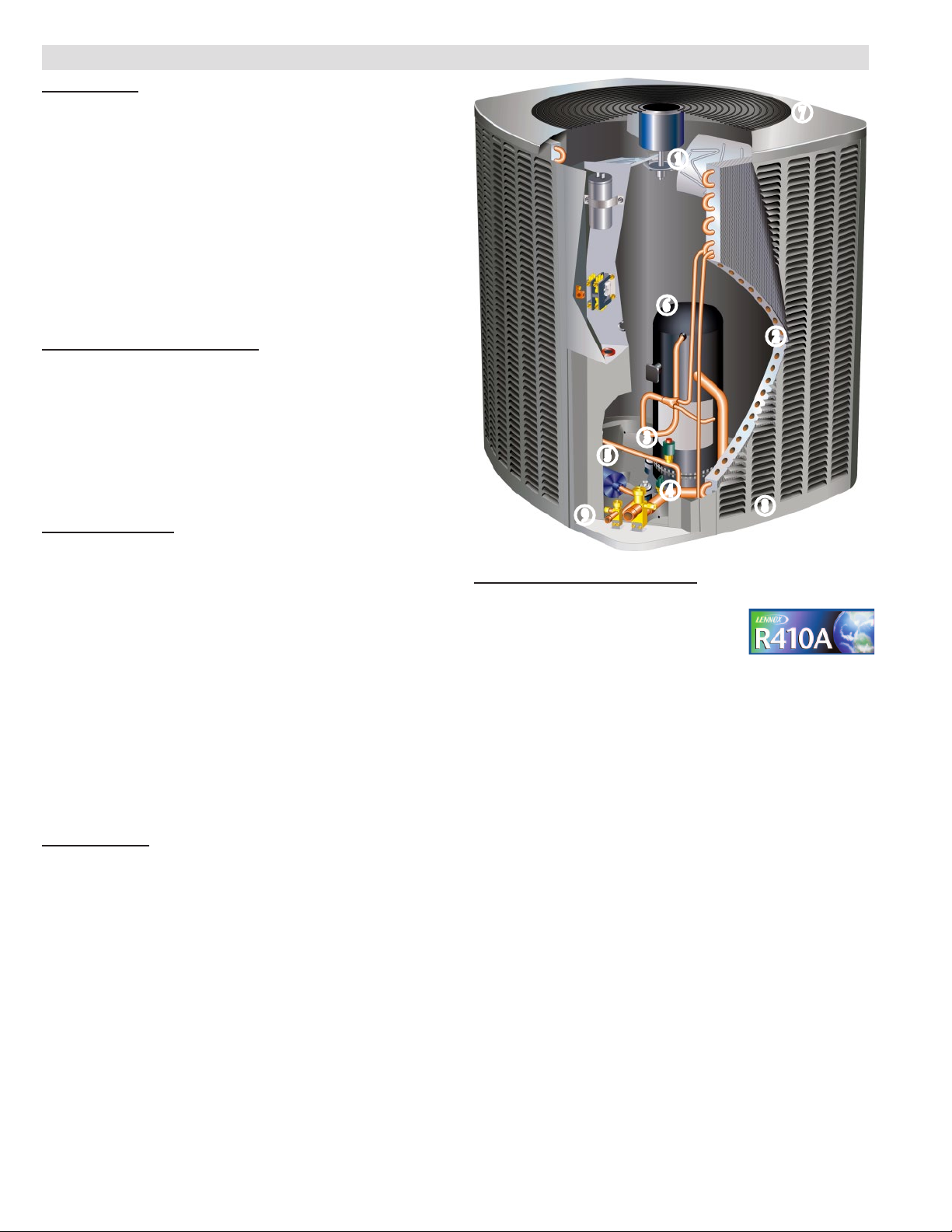
REFRIGERATION SYSTEM
R-410A Refrigerant
Non-chlorine, ozone friendly, R-410A.
Unit pre-charged with refrigerant.
See Specication table.
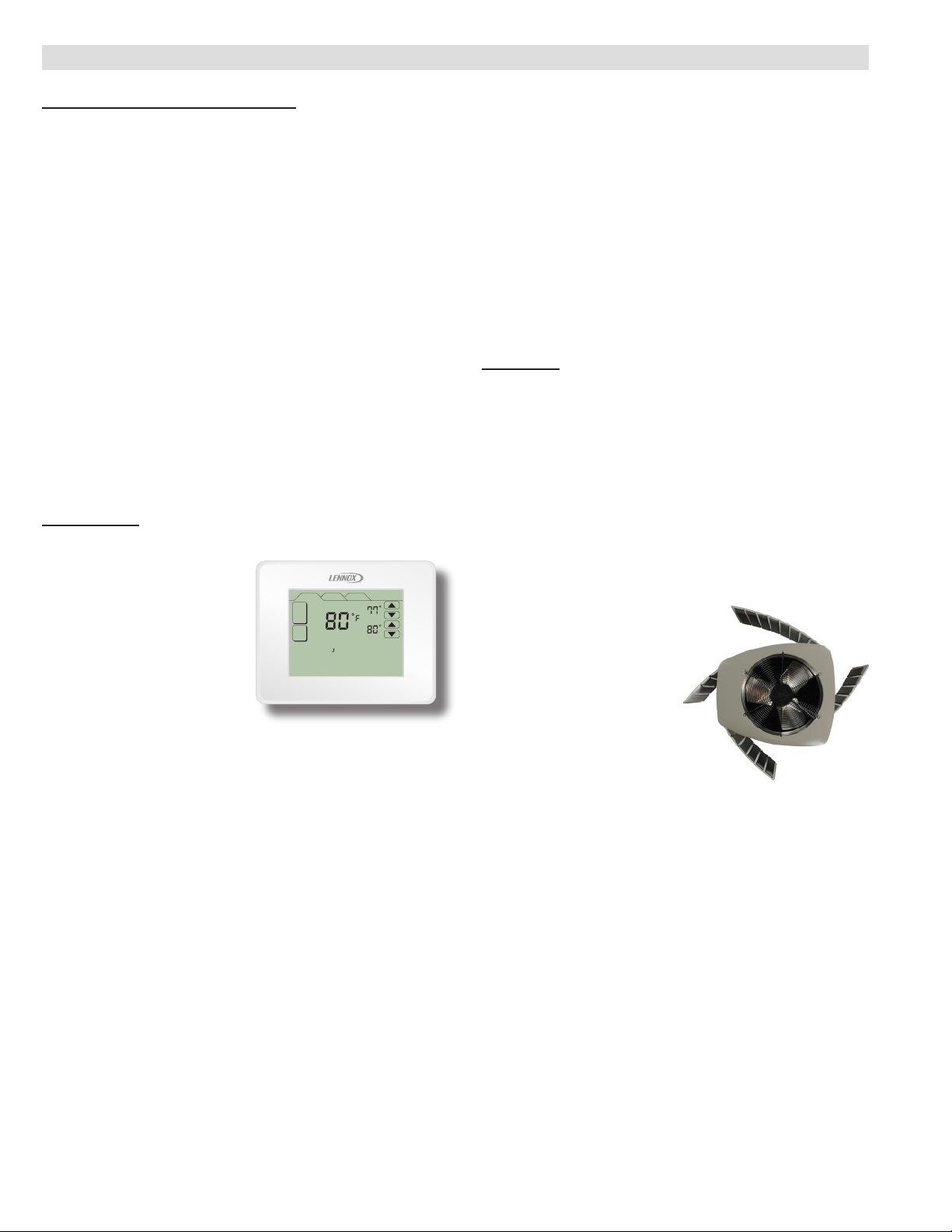
Outdoor Coil Fan
B
Direct drive fan moves large air volumes uniformly
through entire condenser coil for high refrigerant cooling
capacity.
Vertical air discharge minimizes operating sounds and
eliminates damage to lawn and shrubs.
Fan motor has sleeve bearings and is inherently
protected.
Motor totally enclosed for maximum protection from
weather, dust and corrosion
Fan guard constructed of corrosion-resistant PVC
(polyvinyl chloride) coated steel.
Fan service access accomplished by removal of fan
guard.
Copper Tube/Enhanced Fin Coil
C
Lennox designed and fabricated coil.
Ripple-edged aluminum ns.
Copper tube construction.
Lanced ns provide maximum exposure of n surface to
air stream resulting in excellent heat transfer.
Fin collars grip tubing for maximum contact area.
Flared shoulder tubing connections/silver soldering
construction.
Coil is factory tested under high pressure to insure
leakproof construction.
Entire coil is accessible for cleaning.
I
A
Page 3
FEATURES
REFRIGERATION SYSTEM (CONTINUED)
High Pressure Switch
D
Shuts off unit if abnormal operating conditions cause the
discharge pressure to rise above setting.
Protects compressor from excessive condensing
pressure.
Manual reset.
Low Pressure Switch
E
Shuts off unit if suction pressure falls below setting.
Provides loss of charge and freeze-up protection.
Automatic reset.
Hi-Capacity Liquid Line Drier
F
Factory installed in the liquid line, the drier traps
moisture or dirt that could contaminate the refrigerant
system.
100% molecular-sieve bead type drier.
OPTIONS
Expansion Valve Kits
Must be ordered extra and eld installed on certain
indoor units. See Specication table and TXV
Substitution table.
Chatleff style tting.
Freezestat
Installs on or near the discharge line of the indoor coil or
on the suction line.
Senses suction line temperature and cycles the
compressor off when suction line temperature falls
below it’s setpoint.
Opens at 29°F and closes at 58°F.
Refrigerant Line Kits
Refrigerant lines (suction & liquid) are shipped
refrigeration clean. Lines are cleaned, dried,
pressurized, and sealed at factory.
Suction line fully insulated.
L15 lines are stubbed at both ends.
See Specications table for selection.
Not available for -060 model and must be eld
fabricated.
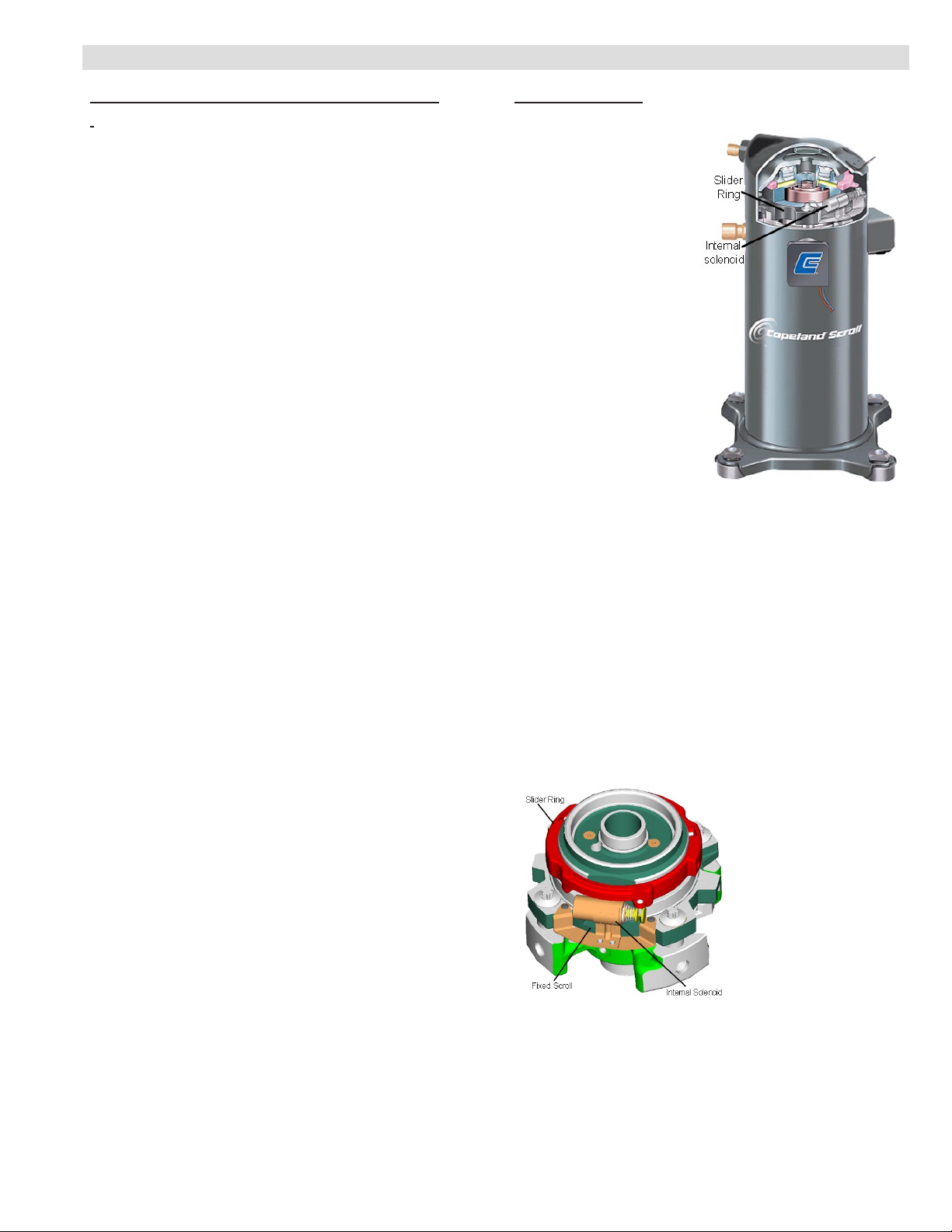
COMPRESSOR
Copeland Scroll Ultra Tech™ Two-Stage Compressor
G
Compressor features high
efciency with uniform
suction ow, constant
discharge ow and high
volumetric efciency and
quiet operation.
Compressor consists
of two involute spiral
scrolls matched together
to generate a series of
crescent shaped gas
pockets between them.
During compression, one
scroll remains stationary
while the other scroll
orbits around it.
Gas is drawn into the
outer pocket, the pocket
is sealed as the scroll
rotates.
As the spiral movement continues, gas pockets are
pushed to the center of the scrolls. Volume between the
pockets is simultaneously reduced.
When pocket reaches the center, gas is now at high
pressure and is forced out of a port located in the
center of the xed scrolls. During compression, several
pockets are compressed simultaneously resulting in a
smooth continuous compression cycle.
Continuous ank contact, maintained by centrifugal
force, minimizes gas leakage and maximizes efciency.
Scroll compressor is tolerant to the effects of slugging
and contaminants. If this occurs, scrolls separate,
allowing liquid or contaminants to be worked toward the
center and discharged.
On the xed scroll there
are two bypass ports in
the rst suction pocket. On
the outside of the xed
scroll there is a “slider
ring” that is controlled by
an internal solenoid that
will rotate and cover the
bypass ports. When the
thermostat calls for
rst-stage cooling, the
bypass ports are open and
the compressor operates
at 67% capacity, creating more cost-effective and
efcient compressor operation. The bypassed
refrigerant is returned to the compressor housing
through the bypass ports. When the thermostat calls for
second-stage cooling, the internal solenoid is energized,
the slider ring rotates and covers the bypass ports, and
the compressor operates at full capacity.
Low gas pulses during compression reduces
operational sound levels.
XC16 - 2 to 5 Ton Heat Pump / Page 3
Page 4
FEATURES
COMPRESSOR (CONTINUED)
Compressor motor is internally protected from
excessive current and temperature.
Compressor is installed in the unit on specially
formulated, resilient rubber mounts for better sound
dampening and vibration free operation.
Crankcase Heater
Crankcase heater prevents migration of liquid
refrigerant into compressor and ensures proper
compressor lubrication.
OPTIONS
Compressor Hard Start Kit
Single-phase units are equipped with a PSC
compressor motor.
This type of motor normally does not need a potential
relay and start capacitor.
In conditions such as low voltage, kit may be required to
increase the compressor starting torque.
Hard start kit is required in applications where the
supply voltage is less than 230V.
CONTROLS
OPTIONS
ComfortSense® 7000
Touchscreen Thermostat
Electronic 7-day, universal,
multi-stage, programmable,
touchscreen thermostat.
HOME SCHEDULE OPTIONS
MODE
AUTO
ON
SCHED
INDOOR RH 26%
WED AN 21 12:35AM
SETAT
HEAT
SETAT
COOL
4 Heat/2 Cool.
Auto-changeover.
Controls humidity during
cooling mode.
Offers enhanced capabilities including humidication /
dehumidication / dewpoint measurement and control,
Humiditrol® control, and equipment maintenance
reminders.
Easy-to-use, menu driven thermostat with a back-lit,
LCD touchscreen.
Remote outdoor temperature sensor (optional) allows
the thermostat to display outdoor temperature. Required
in dual fuel and Humiditrol® applications.
See the ComfortSense 7000 Engineering Handbook
bulletin in the Controls section for more information.
Indoor Blower Off Delay Relay
Delays the indoor blower-off time during the cooling
cycle.
See AHRI System Matches for usage.
Indoor Blower Speed Relay
Relay kit provides optimum humidity control conditions
by automatically reducing indoor blower speed during
continuous fan or rst-stage compressor operation.
Low Ambient Kit
Air conditioner will operate satisfactorily down to 45°F
outdoor air temperature without any additional controls.
Kit can be added in the eld enabling unit to operate
properly down to 30°F.
A Freezestat should be installed on compressors
equipped with a low ambient kit.
A Compressor Low Ambient Cut-Off should be added to
terminate compressor operation below recommended
operation conditions.
Thermostat
Thermostat not furnished with unit. See Thermostat
bulletins in Controls Section and Lennox Price Book.
CAbinet
Heavy-gauge steel construction
H
Pre-painted cabinet nish.
Painted base section.
Control box is conveniently located with all controls
factory wired.
Large removable panel provides service access.
Drainage holes are provided in base section for
moisture removal.
High density polyethylene unit support feet raise the
unit off of the mounting surface, away from damaging
moisture.
SmartHinge™ Louvered Coil Protection
I
Steel louvered panels
provides complete coil
protection.
Panels are hinged to allow
easy cleaning and servicing
of coils.
Panels may be completely
removed.
Interlocking tabs and slots
assure tight t on cabinet.
Refrigerant Line Connections, Electrical Inlets and
J
Service Valves
Suction and liquid lines are located on corner of unit
cabinet and are made with sweat connections. See
dimension drawing.
Fully serviceable brass service valves prevent corrosion
and provide access to refrigerant system. Suction valve
can be fully shut off, while liquid valve may be front
seated to manage refrigerant charge while servicing
system.
Refrigerant line connections and eld wiring inlets
are located in one central area of the cabinet. See
dimension drawing.
XC16 - 2 to 5 Ton Heat Pump / Page 4
Page 5

SPECIFICATIONS
General
Data
Connections
(sweat)
Refrigerant
Outdoor
Net face area - sq. ft. Outer coil 21.00 24.5 21.00 24.93
Liquid line (o.d.) - in. 3/8 3/8 3/8 3/8
Suction line (o.d.) - in. 3/4 7/8 7/8 1-1/8
1
R-410A charge furnished 7 lbs. 6 oz. 8 lbs. 8 oz. 11 lbs. 4 oz. 14 lbs. 2 oz.
Coil
Tube diameter - in. 5/16 5/16 5/16 5/16
Outdoor
Fan
Shipping Data - lbs. 1 pkg. 230 249 268 323
ELECTRICAL DATA
Line voltage data - 60hz
2
Maximum overcurrent protection (amps) 20 35 45 60
3
Minimum circuit ampacity 13.6 22.0 28.2 33.9
Compressor Rated load amps 10.3 16.7 21.2 25.9
Locked rotor amps 52 82 96 118
Outdoor Fan
Motor
Locked Rotor amps 2.1 2.1 3.1 2.9
OPTIONAL ACCESSORIES - must be ordered extra
®
ComfortSense
7000 Thermostat Y2081
Outdoor Temperature Sensor - for
ComfortSense 7000 Thermostat
Compressor Hard Start Kit - Required in
applications with less than 230V
Compressor Low Ambient Cut-Off 45F08
Compressor Time-Off Control 47J27
Freezestat 3/8 in. tubing 93G35
5/8 in. tubing 50A93
Indoor Blower Off Delay Relay 58M81
Indoor Blower Speed Relay 40K58
Low Ambient Kit 34M72
Refrigerant
Line Sets
L15-41-20 L15-41-40
L15-41-30 L15-41-50
L15-65-30 L15-65-40
NOTE - Extremes of operating range are plus 10% and minus 5% of line voltage.
1
Refrigerant charge sufcient for 15 ft. length of refrigerant lines.
2
HACR type breaker or fuse.
3
Refer to National or Canadian Electrical Code manual to determine wire, fuse and disconnect size requirements.
4
Hard start kit is required in applications where the supply voltage is less than 230V.
Model No. XC16-024 XC16-036 XC16-048 XC16-060
Nominal Tonnage 2 3 4 5
Inner coil - - - - - - 20.27 24.14
No. of rows 1 1 2 2
Fins per inch 26 26 22 22
Diameter - in. 22 22 22 26
No. of blades 4 4 4 3
Motor hp 1/6 1/6 1/4 1/3
Cfm 3230 3260 3955 4380
Rpm 840 840 835 850
Watts 215 220 320 280
4
230V-1ph
4
230V-1ph
4
230V-1ph
4
230V-1ph
Power factor 0.98 0.99 0.99 0.99
Full load amps 1.1 1.1 1.7 1.8
X2658
10J42
81J69
L15-65-50
Field Fabricate
XC16 - 2 to 5 Ton Heat Pump / Page 5
Page 6
OUTDOOR SOUND DATA
Octave Band Sound Power Levels dBA, re 10-
1
Unit
Model No.
XC16-024
XC16-036
XC16-048
XC16-060
NOTE - the octave sound power data does not include tonal correction.
1
Tested according to AHRI Standard 270-2008 test conditions.
63 125 250 500 1000 2000 4000 8000
50 55 62 67 68.5 65.5 63 58.5 74
50.5 54.5 61 68 67 63 63 59.5 76
81.5 72 72 72.5 68.5 64.5 59.5 56.5 76
79 71 70.5 76.5 71 65 61.5 57.5 78
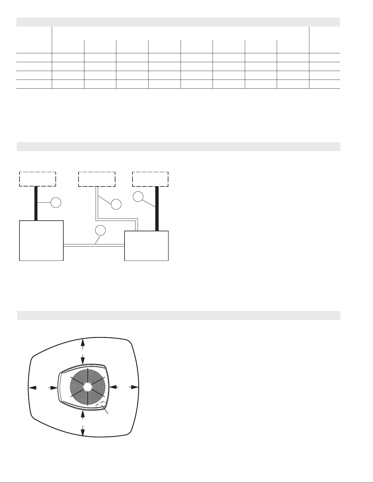
FIELD WIRING
Center Frequency - HZ
12
Watts
1
Sound
Rating
Number
(dB)
DISCONNECT
SWITCH
(By Others)
B
THERMOSTAT
(Optional)
D
C
LENNOX
AIR
CONDITIONER
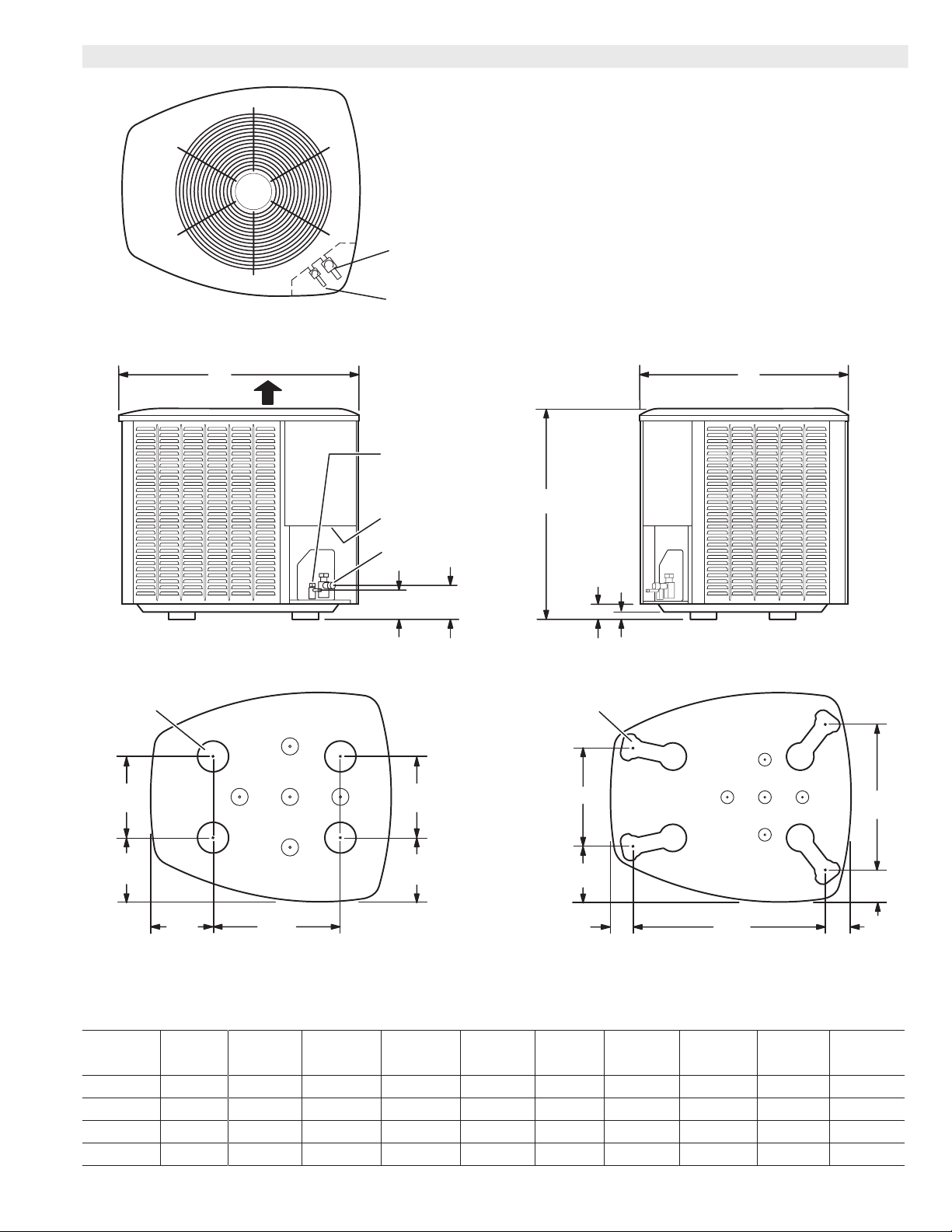
INSTALLATION CLEARANCES
See NOTES
DISCONNECT
SWITCH
(By Others)
A
LENNOX
HEATING UNIT
OR
AIR HANDLER
UNIT
A - Two Wire Power (not furnished)
B - Two Power (not furnished). See Electrical Data
C - Four Wire Low Voltage (not furnished). 18 ga. minimum
D - Six Wire Low Voltage (not furnished). 18 ga. minimum
All wiring must conform to NEC or CEC and local electrical codes.
NOTES:
Service clearance of 30 in. (762 mm) must be maintained on one
of the sides adjacent to the control box.
See
NOTES
See NOTES
XC16 - 2 to 5 Ton Heat Pump / Page 6
See
NOTES
Control
Box
Clearance to one of the other three sides must be 36 in. (914 mm)
Clearance to one of the remaining two sides may be 12 in. (305
mm) and the final side may be 6 in. (152 mm).
A clearance of 24 in. (610 mm) must be maintained between two
units.
48 in. (1219 mm) clearance required on top of unit.
Page 7
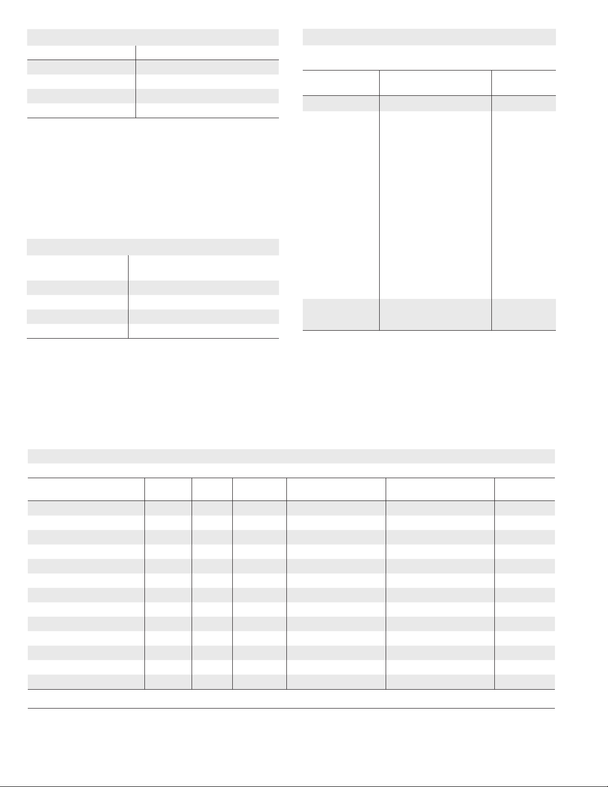
DIMENSIONS - INCHES (MM)
(216)
TOP VIEW
DISCHARGE AIR
SUCTION LINE
CONNECTION
LIQUID LINE
CONNECTION
BC
LIQUID LINE
CONNECTION
UNIT SUPPORT
FEET
8−1/2
8−3/4
(222)
5−1/2
(140)
4−1/4(108)
SIDE VIEW
13−1/2
(343)
XC16-024 BASE SECTION
ELECTRICAL
INLETS
SUCTION LINE
CONNECTION
4−3/4
(121)
9−1/2
(241)
8−1/4
(210)
A
2 (51)
UNIT SUPPORT
FEET
D
E
1 (25)
F
END VIEW
G
H
XC16-036 TO -060 BASE SECTION
K
J
Model No.
A B C D E F G H J K
in. mm in. mm in. mm in. mm in. mm in. mm in. mm in. mm in. mm in. mm
XC16-024 39 991 30-1/2 775 35 889 - - - - - - - - - - - - - - - - - - - - - - - - - - - - - - - - - - - - - - - - - -
XC16-036 45 1143 30-1/2 775 35 889 13-7/8 352 7-3/4 197 3-1/4 83 27-1/8 689 3-5/8 92 4-1/2 114 20-5/8 524
XC16-048 39 991 30-1/2 775 35 889 13-7/8 352 7-3/4 197 3-1/4 83 27-1/8 689 3-5/8 92 4-1/2 114 20-5/8 524
XC16-060 39 991 35-1/2 902 39-1/2 1003 16-7/8 429 8-3/4 222 3-1/8 79 30-3/4 781 4-5/8 117 3-3/4 95 26-7/8 683
XC16 - 2 to 5 Ton Heat Pump / Page 7
Page 8
THERMAL EXPANSION VALVES (TXV)
Model No. Order No.
XC16-024 37L51
XC16-036 37L51
XC16-048 91M02
XC16-060 91M02
CX34 upow coils and all Lennox air handlers (except CB26UH “R”) are
shipped with a factory installed TXV. In most cases, no change out of the valve
is needed.
If a change out is required it will be listed in the “TXV SUBSTITUTIONS” table.
The correct TXV must be ordered and eld installed. C33 coils and all horizontal
and downow coils are shipped without a TXV. The TXV must be ordered and
eld installed.
MOST POPULAR MATCHES
Outdoor Unit
Model No.
XC16-024 CX34-36B with G60UHV-36B-040
XC16-036 CX34-43C with G60UHV-60C-110
XC16-048 CX34-62C with G60UHV-60C-090
XC16-060 CX34-62C with G60UHV-60C-090
Indoor Unit
Model No
*tXV SUBSTITUTIONS
Indoor Coils/Air Handlers with factory installed expansion
valves that require eld replacement
Model No.
XC16-024 CBX26UH-024 37L51
XC16-036 CX34-42 37L51
XC16-036 CX34-43 37L51
XC16-036 CX34-44/48 37L51
XC16-036 CX34-49 37L51
XC16-036 CBX26UH-030 37L51
XC16-036 CBX27UH-072 37L51
XC16-036 CBX32M-042 37L51
XC16-036 CBX32MV-024/030 37L51
XC16-036 CBX32MV-048 37L51
XC16-036 CBX40UHV-030 37L51
XC16-036 CBX40UHV-042 37L51
XC16-036 CBX40UHV-048 37L51
XC16-048 CX34-44/48 91M02
XC16-048 CBX26UH-042 91M02
*CX34 coils and all air handlers (except CB26UH “R”) - the factory installed
expansion valve must be replaced with the expansion valve listed (ordered
separately). If the combination is not listed above, the factory installed TXV is
used.
C33 and CH33 coils and CB26UH “R” air handlers - use the RFC shipped with
the outdoor unit or replace the factory installed RFC with the expansion valve
listed in the Thermal Expansion Valves Table.
CR33 and CH23 - use the RFC shipped with the outdoor unit or use the expansion valve listed in the Thermal Expansion Valves Table.
Indoor Coil or Air
Handler
Order No.
AHRI SYSTEM MATCHES
NOTE - For the latest up-to-date system matches please visit the AHRI web site at http://www.ahridirectory.org
Model
No.
Capacity SEER EER
XC16-024-230 + TXV 25,200 15.70 12.70 C33-19 CBWMV-24B-040 3496089
XC16-024-230 + TXV 25,400 16.50 12.70 C33-19 G60UHV-36A-070 3069061
XC16-024-230 + TXV 24,800 14.20 11.50 C33-19 3069056
XC16-024-230 + TXV 25,800 16.50 13.00 C33-25 G60UHV-36A-070 3069062
XC16-024-230 + TXV 26,000 16.70 13.20 C33-25 G60UHV-36B-090 3069063
XC16-024-230 + TXV 26,000 16.50 13.00 C33-25 G61MPV-36B-045 3069064
XC16-024-230 + TXV 25,800 16.50 13.00 C33-25 G61MPV-36B-070 3069065
XC16-024-230 + TXV 25,800 16.50 13.00 C33-25 G71MPP-36B-070 3069066
XC16-024-230 + TXV 25,200 14.20 11.70 C33-25 3069057
XC16-024-230 + TXV 25,200 16.00 12.70 C33-30 G60UHV-36A-070 3069067
XC16-024-230 + TXV 25,200 16.00 12.70 C33-30 G60UHV-36B-090 3069068
XC16-024-230 + TXV 25,200 15.70 12.50 C33-30 G61MPV-36B-045 3069069
XC16-024-230 + TXV 25,200 15.70 12.70 C33-30 G61MPV-36B-070 3069070
NOTES:
+ TXV = Matched with Thermostatic Expansion Valve.
Ratings are certied in accordance with USE certication program which is based on AHRI Standard 210/240; 95°F outdoor air temperature, 80°F db / 67°F wb entering
evaporator air with 25 ft. of connecting refrigerant lines.
All ratings include the use of a blower time delay relay (TDR). All Lennox variable-speed furnaces and Air Handlers have time delay capabilities. Other Furnaces and Air
Handlers may require an optional time delay relay (58M81) for eld installation. See furnace or air handler specications to determine if relay is needed.
Also see TXV Substitutions Table.
Coil or
Air Handler
Furnace
AHRI
Reference
XC16 - 2 to 5 Ton Heat Pump / Page 8
Page 9

AHRI SYSTEM MATCHES
NOTE - For the latest up-to-date system matches please visit the AHRI web site at http://www.ahridirectory.org
Model
No.
Capacity SEER EER
XC16-024-230 + TXV 25,200 16.00 12.50 C33-30 G61MPV-36B-071 3069072
XC16-024-230 + TXV 25,000 16.00 12.70 C33-30 G61MPV-36C-090 3069163
XC16-024-230 + TXV 25,200 15.70 12.70 C33-30 G71MPP-36B-070 3069071
XC16-024-230 + TXV 25,000 16.00 12.70 C33-30 G71MPP-36C-090 3069164
XC16-024-230 + TXV 26,200 16.70 13.20 C33-31 G60UHV-36A-070 3069073
XC16-024-230 + TXV 26,400 17.00 13.50 C33-31 G60UHV-36B-090 3069074
XC16-024-230 + TXV 26,400 16.70 13.20 C33-31 G61MPV-36B-045 3069075
XC16-024-230 + TXV 26,200 16.70 13.20 C33-31 G61MPV-36B-070 3069076
XC16-024-230 + TXV 26,400 16.70 13.20 C33-31 G61MPV-36B-071 3069078
XC16-024-230 + TXV 26,200 16.70 13.20 C33-31 G71MPP-36B-070 3069077
XC16-024-230 + TXV 25,600 14.50 12.00 C33-31 3069058
XC16-024-230 + TXV 25,200 15.50 12.70 C33-36 CBWMV-24B-040 3493246
XC16-024-230 + TXV 25,800 16.50 13.00 C33-36 G60UHV-36A-070 3069079
XC16-024-230 + TXV 25,400 16.00 12.70 C33-36 G60UHV-36B-090 3068760
XC16-024-230 + TXV 25,800 16.50 13.00 C33-36 G61MPV-36B-045 3069080
XC16-024-230 + TXV 25,800 16.50 13.00 C33-36 G61MPV-36B-070 3069081
XC16-024-230 + TXV 25,800 16.50 13.00 C33-36 G61MPV-36B-071 3069083
XC16-024-230 + TXV 25,600 16.50 13.20 C33-36 G61MPV-36C-090 3069084
XC16-024-230 + TXV 25,800 16.50 13.00 C33-36 G71MPP-36B-070 3069082
XC16-024-230 + TXV 25,600 16.50 13.20 C33-36 G71MPP-36C-090 3069085
XC16-024-230 + TXV 24,600 13.70 11.50 C33-36 3069059
XC16-024-230 + TXV 26,400 17.00 13.20 C33-38 G60UHV-36A-070 3069086
XC16-024-230 + TXV 26,600 17.00 13.50 C33-38 G60UHV-36B-090 3069087
XC16-024-230 + TXV 26,600 16.70 13.20 C33-38 G61MPV-36B-045 3069088
XC16-024-230 + TXV 26,400 17.00 13.20 C33-38 G61MPV-36B-070 3069089
XC16-024-230 + TXV 26,600 17.00 13.20 C33-38 G61MPV-36B-071 3069091
XC16-024-230 + TXV 26,400 17.00 13.20 C33-38 G71MPP-36B-070 3069090
XC16-024-230 + TXV 25,400 14.20 11.70 C33-38 3069060
XC16-024-230 + TXV 26,000 15.20 12.50 CB26UH-024 3069092
XC16-024-230 + TXV 26,000 16.20 13.20 CB27UH-024-230 3069094
XC16-024-230 + TXV 26,200 17.00 13.50 CB27UH-030-230 3069095
XC16-024-230 + TXV 25,400 14.50 12.00 CB30M-21/26P 3069093
XC16-024-230 + TXV 26,000 15.20 12.50 CBX26UH-024 3068837
XC16-024-230 + TXV 26,000 16.20 13.20 CBX27UH-024-230 3068841
XC16-024-230 + TXV 26,200 17.00 13.50 CBX27UH-030-230 3068842
XC16-024-230 + TXV 25,400 14.50 12.00 CBX32M-018/024 3068838
XC16-024-230 + TXV 25,400 15.50 12.20 CBX32MV-018/024 3068839
XC16-024-230 + TXV 25,600 15.50 12.50 CBX32MV-024/030 3068840
XC16-024-230 + TXV 25,400 15.50 12.20 CBX40UHV-024 3291609
XC16-024-230 + TXV 25,600 15.50 12.50 CBX40UHV-030 3291634
XC16-024-230 + TXV 24,600 16.00 12.70 CH23-31 G61MPV-36B-070 3068814
XC16-024-230 + TXV 24,600 16.00 12.70 CH23-31 G71MPP-36B-070 3068815
NOTES:
+ TXV = Matched with Thermostatic Expansion Valve.
Ratings are certied in accordance with USE certication program which is based on AHRI Standard 210/240; 95°F outdoor air temperature, 80°F db / 67°F wb entering
evaporator air with 25 ft. of connecting refrigerant lines.
All ratings include the use of a blower time delay relay (TDR). All Lennox variable-speed furnaces and Air Handlers have time delay capabilities. Other Furnaces and Air
Handlers may require an optional time delay relay (58M81) for eld installation. See furnace or air handler specications to determine if relay is needed.
Also see TXV Substitutions Table.
Coil or
Air Handler
Furnace
AHRI
Reference
XC16 - 2 to 5 Ton Heat Pump / Page 9
Page 10

AHRI SYSTEM MATCHES
NOTE - For the latest up-to-date system matches please visit the AHRI web site at http://www.ahridirectory.org
Model
No.
Capacity SEER EER
XC16-024-230 + TXV 24,000 13.50 11.00 CH23-31 3068767
XC16-024-230 + TXV 25,800 16.50 13.00 CH23-41 G60UHV-36A-070 3068816
XC16-024-230 + TXV 25,200 14.20 11.70 CH23-41 3068768
XC16-024-230 + TXV 25,400 16.20 12.70 CH33-19 G60UHV-36A-070 3068817
XC16-024-230 + TXV 24,800 14.00 11.50 CH33-19 3068769
XC16-024-230 + TXV 25,200 16.00 12.70 CH33-24/30 G60UHV-36A-070 3068818
XC16-024-230 + TXV 24,600 14.00 11.50 CH33-24/30 3068843
XC16-024-230 + TXV 26,000 16.50 13.00 CH33-25A G60UHV-36A-070 3068819
XC16-024-230 + TXV 25,400 14.50 11.70 CH33-25A 3068772
XC16-024-230 + TXV 25,800 16.70 13.20 CH33-25B G60UHV-36B-090 3068820
XC16-024-230 + TXV 25,800 16.50 13.00 CH33-25B G61MPV-36B-045 3068821
XC16-024-230 + TXV 25,800 16.50 13.00 CH33-25B G61MPV-36B-070 3068822
XC16-024-230 + TXV 26,000 16.50 13.00 CH33-25B G61MPV-36B-071 3068824
XC16-024-230 + TXV 25,800 16.50 13.00 CH33-25B G71MPP-36B-070 3068823
XC16-024-230 + TXV 25,200 14.20 11.70 CH33-25B 3068773
XC16-024-230 + TXV 26,400 16.70 13.20 CH33-31A G60UHV-36A-070 3068825
XC16-024-230 + TXV 25,800 14.70 12.00 CH33-31A 3068774
XC16-024-230 + TXV 26,600 17.00 13.50 CH33-31B G60UHV-36B-090 3068826
XC16-024-230 + TXV 26,400 16.70 13.20 CH33-31B G61MPV-36B-045 3068827
XC16-024-230 + TXV 26,400 16.70 13.20 CH33-31B G61MPV-36B-070 3068828
XC16-024-230 + TXV 26,600 17.00 13.20 CH33-31B G61MPV-36B-071 3068830
XC16-024-230 + TXV 26,400 16.70 13.20 CH33-31B G71MPP-36B-070 3068829
XC16-024-230 + TXV 25,800 14.50 12.00 CH33-31B 3068775
XC16-024-230 + TXV 25,600 16.20 12.70 CH33-36A G60UHV-36A-070 3068831
XC16-024-230 + TXV 25,200 14.20 11.70 CH33-36A 3068770
XC16-024-230 + TXV 25,800 16.70 13.20 CH33-36B G60UHV-36B-090 3068832
XC16-024-230 + TXV 25,800 16.20 13.00 CH33-36B G61MPV-36B-045 3068833
XC16-024-230 + TXV 25,800 16.50 13.00 CH33-36B G61MPV-36B-070 3068834
XC16-024-230 + TXV 25,800 16.50 13.00 CH33-36B G61MPV-36B-071 3068836
XC16-024-230 + TXV 25,800 16.50 13.00 CH33-36B G71MPP-36B-070 3068835
XC16-024-230 + TXV 25,000 14.20 11.70 CH33-36B 3068771
XC16-024-230 + TXV 26,200 16.70 13.00 CR33-30/36 G60DFV-36A-070 3068808
XC16-024-230 + TXV 26,600 17.20 13.50 CR33-30/36 G60DFV-36B-090 3068809
XC16-024-230 + TXV 26,200 16.70 13.20 CR33-30/36 G61MPV-36B-045 3068810
XC16-024-230 + TXV 26,200 16.70 13.20 CR33-30/36 G61MPV-36B-070 3068811
XC16-024-230 + TXV 26,200 16.70 13.20 CR33-30/36 G61MPV-36B-071 3068813
XC16-024-230 + TXV 26,200 16.70 13.20 CR33-30/36 G71MPP-36B-070 3068812
XC16-024-230 + TXV 25,400 14.50 11.70 CR33-30/36 3068766
XC16-024-230 + TXV 25,200 15.70 12.70 CX34-18/24 CBWMV-24B-040 3496087
XC16-024-230 + TXV 25,400 16.50 12.70 CX34-18/24 G60UHV-36A-070 3493257
XC16-024-230 + TXV 24,800 14.20 11.50 CX34-18/24 3493256
XC16-024-230 + TXV 25,400 16.50 12.70 CX34-19 G60UHV-36A-070 3068776
NOTES:
+ TXV = Matched with Thermostatic Expansion Valve.
Ratings are certied in accordance with USE certication program which is based on AHRI Standard 210/240; 95°F outdoor air temperature, 80°F db / 67°F wb entering
evaporator air with 25 ft. of connecting refrigerant lines.
All ratings include the use of a blower time delay relay (TDR). All Lennox variable-speed furnaces and Air Handlers have time delay capabilities. Other Furnaces and Air
Handlers may require an optional time delay relay (58M81) for eld installation. See furnace or air handler specications to determine if relay is needed.
Also see TXV Substitutions Table.
Coil or
Air Handler
Furnace
AHRI
Reference
XC16 - 2 to 5 Ton Heat Pump / Page 10
Page 11

AHRI SYSTEM MATCHES
NOTE - For the latest up-to-date system matches please visit the AHRI web site at http://www.ahridirectory.org
Model
No.
Capacity SEER EER
XC16-024-230 + TXV 24,800 14.20 11.50 CX34-19 3068761
XC16-024-230 + TXV 25,800 16.50 13.00 CX34-25 G60UHV-36A-070 3068777
XC16-024-230 + TXV 26,000 16.70 13.20 CX34-25 G60UHV-36B-090 3068778
XC16-024-230 + TXV 26,000 16.50 13.00 CX34-25 G61MPV-36B-045 3068779
XC16-024-230 + TXV 25,800 16.50 13.00 CX34-25 G61MPV-36B-070 3068780
XC16-024-230 + TXV 25,800 16.50 13.00 CX34-25 G71MPP-36B-070 3068781
XC16-024-230 + TXV 25,200 14.20 11.70 CX34-25 3068762
XC16-024-230 + TXV 25,200 16.00 12.70 CX34-30 G60UHV-36A-070 3068782
XC16-024-230 + TXV 25,200 16.00 12.70 CX34-30 G60UHV-36B-090 3068783
XC16-024-230 + TXV 25,200 15.70 12.50 CX34-30 G61MPV-36B-045 3068784
XC16-024-230 + TXV 25,200 15.70 12.70 CX34-30 G61MPV-36B-070 3068785
XC16-024-230 + TXV 25,200 16.00 12.50 CX34-30 G61MPV-36B-071 3068787
XC16-024-230 + TXV 25,000 16.00 12.70 CX34-30 G61MPV-36C-090 3068844
XC16-024-230 + TXV 25,200 15.70 12.70 CX34-30 G71MPP-36B-070 3068786
XC16-024-230 + TXV 25,000 16.00 12.70 CX34-30 G71MPP-36C-090 3068845
XC16-024-230 + TXV 26,200 16.70 13.20 CX34-31 G60UHV-36A-070 3068788
XC16-024-230 + TXV 26,400 17.00 13.50 CX34-31 G60UHV-36B-090 3068789
XC16-024-230 + TXV 26,400 16.70 13.20 CX34-31 G61MPV-36B-045 3068790
XC16-024-230 + TXV 26,200 16.70 13.20 CX34-31 G61MPV-36B-070 3068791
XC16-024-230 + TXV 26,400 16.70 13.20 CX34-31 G61MPV-36B-071 3068793
XC16-024-230 + TXV 26,200 16.70 13.20 CX34-31 G71MPP-36B-070 3068792
XC16-024-230 + TXV 25,600 14.50 12.00 CX34-31 3068763
XC16-024-230 + TXV 25,200 15.50 12.70 CX34-36 CBWMV-24B-040 3493247
XC16-024-230 + TXV 25,800 16.50 13.00 CX34-36 G60UHV-36A-070 3068794
XC16-024-230 + TXV 25,800 16.70 13.20 CX34-36 G60UHV-36B-090 3068795
XC16-024-230 + TXV 25,800 16.50 13.00 CX34-36 G61MPV-36B-045 3068796
XC16-024-230 + TXV 25,800 16.50 13.00 CX34-36 G61MPV-36B-070 3068797
XC16-024-230 + TXV 25,800 16.50 13.00 CX34-36 G61MPV-36B-071 3068799
XC16-024-230 + TXV 25,600 16.50 13.20 CX34-36 G61MPV-36C-090 3068800
XC16-024-230 + TXV 25,800 16.50 13.00 CX34-36 G71MPP-36B-070 3068798
XC16-024-230 + TXV 25,600 16.50 13.20 CX34-36 G71MPP-36C-090 3068801
XC16-024-230 + TXV 24,600 13.70 11.50 CX34-36 3068764
XC16-024-230 + TXV 26,400 17.00 13.20 CX34-38 G60UHV-36A-070 3068802
XC16-024-230 + TXV 26,600 17.00 13.50 CX34-38 G60UHV-36B-090 3068803
XC16-024-230 + TXV 26,600 16.70 13.20 CX34-38 G61MPV-36B-045 3068804
XC16-024-230 + TXV 26,400 17.00 13.20 CX34-38 G61MPV-36B-070 3068805
XC16-024-230 + TXV 26,600 17.00 13.20 CX34-38 G61MPV-36B-071 3068807
XC16-024-230 + TXV 26,400 17.00 13.20 CX34-38 G71MPP-36B-070 3068806
XC16-024-230 + TXV 25,400 14.20 11.70 CX34-38 3068765
XC16-036-230 + TXV 34,400 15.50 11.20 C33-36 CBWMV-36C-090 3184066
XC16-036-230 + TXV 34,200 15.00 11.00 C33-36 G60UHV-36A-070 3069103
XC16-036-230 + TXV 34,600 15.70 11.50 C33-36 G60UHV-36B-090 3069104
NOTES:
+ TXV = Matched with Thermostatic Expansion Valve.
Ratings are certied in accordance with USE certication program which is based on AHRI Standard 210/240; 95°F outdoor air temperature, 80°F db / 67°F wb entering
evaporator air with 25 ft. of connecting refrigerant lines.
All ratings include the use of a blower time delay relay (TDR). All Lennox variable-speed furnaces and Air Handlers have time delay capabilities. Other Furnaces and Air
Handlers may require an optional time delay relay (58M81) for eld installation. See furnace or air handler specications to determine if relay is needed.
Also see TXV Substitutions Table.
Coil or
Air Handler
Furnace
AHRI
Reference
XC16 - 2 to 5 Ton Heat Pump / Page 11
Page 12

AHRI SYSTEM MATCHES
NOTE - For the latest up-to-date system matches please visit the AHRI web site at http://www.ahridirectory.org
Model
No.
Capacity SEER EER
XC16-036-230 + TXV 35,000 16.00 11.50 C33-36 G60UHV-60C-090 3069105
XC16-036-230 + TXV 34,800 15.70 11.50 C33-36 G60UHV-60C-110 3069106
XC16-036-230 + TXV 34,200 15.20 11.00 C33-36 G61MPV-36B-045 3069107
XC16-036-230 + TXV 34,400 15.50 11.00 C33-36 G61MPV-36B-070 3069108
XC16-036-230 + TXV 34,200 15.20 11.00 C33-36 G61MPV-36B-071 3069110
XC16-036-230 + TXV 34,200 15.50 11.50 C33-36 G61MPV-36C-090 3069111
XC16-036-230 + TXV 34,400 15.50 11.00 C33-36 G71MPP-36B-070 3069109
XC16-036-230 + TXV 34,200 15.50 11.50 C33-36 G71MPP-36C-090 3069112
XC16-036-230 + TXV 33,800 13.70 10.70 C33-36 3069097
XC16-036-230 + TXV 35,600 15.70 11.50 C33-38 G60UHV-36A-070 3069113
XC16-036-230 + TXV 35,800 16.20 11.70 C33-38 G60UHV-36B-090 3069114
XC16-036-230 + TXV 35,600 16.00 11.20 C33-38 G61MPV-36B-045 3069115
XC16-036-230 + TXV 35,400 16.00 11.50 C33-38 G61MPV-36B-070 3069116
XC16-036-230 + TXV 35,400 16.00 11.50 C33-38 G61MPV-36B-071 3069118
XC16-036-230 + TXV 35,400 16.00 11.50 C33-38 G71MPP-36B-070 3069117
XC16-036-230 + TXV 34,600 14.00 10.90 C33-38 3069098
XC16-036-230 + TXV 34,400 15.70 11.50 C33-42 G60UHV-36B-090 3069119
XC16-036-230 + TXV 34,200 15.20 11.00 C33-42 G61MPV-36B-045 3069120
XC16-036-230 + TXV 34,000 15.20 11.00 C33-42 G61MPV-36B-070 3069121
XC16-036-230 + TXV 34,000 15.20 11.00 C33-42 G61MPV-36B-071 3069123
XC16-036-230 + TXV 34,000 15.20 11.00 C33-42 G71MPP-36B-070 3069122
XC16-036-230 + TXV 33,800 13.70 10.70 C33-42 3069099
XC16-036-230 + TXV 35,800 16.00 11.70 C33-43 CBWMV-36C-090 3184068
XC16-036-230 + TXV 36,000 16.20 12.00 C33-43 G60UHV-36B-090 3069124
XC16-036-230 + TXV 36,600 16.50 12.00 C33-43 G60UHV-60C-090 3069125
XC16-036-230 + TXV 36,000 16.50 12.00 C33-43 G60UHV-60C-110 3069096
XC16-036-230 + TXV 35,600 16.00 11.50 C33-43 G61MPV-36B-045 3069126
XC16-036-230 + TXV 35,400 16.00 11.50 C33-43 G61MPV-36B-070 3069127
XC16-036-230 + TXV 35,400 16.20 12.00 C33-43 G61MPV-36C-090 3069129
XC16-036-230 + TXV 36,200 16.20 12.00 C33-43 G61MPV-60C-090 3069131
XC16-036-230 + TXV 36,200 16.20 11.70 C33-43 G61MPV-60C-091 3069133
XC16-036-230 + TXV 36,200 16.00 12.00 C33-43 G61MPV-60C-110 3069134
XC16-036-230 + TXV 36,200 16.20 12.00 C33-43 G61MPV-60C-111 3069136
XC16-036-230 + TXV 35,400 16.00 11.50 C33-43 G71MPP-36B-070 3069128
XC16-036-230 + TXV 35,400 16.20 12.00 C33-43 G71MPP-36C-090 3069130
XC16-036-230 + TXV 36,200 16.20 12.00 C33-43 G71MPP-60C-090 3069132
XC16-036-230 + TXV 36,200 16.00 12.00 C33-43 G71MPP-60C-110 3069135
XC16-036-230 + TXV 35,200 14.20 11.00 C33-43 3069100
XC16-036-230 + TXV 36,000 16.20 12.00 C33-44C G60UHV-60C-090 3068758
XC16-036-230 + TXV 35,800 16.20 11.70 C33-44C G60UHV-60C-110 3068697
XC16-036-230 + TXV 35,200 16.00 11.70 C33-44C G61MPV-36C-090 3068698
XC16-036-230 + TXV 35,600 16.20 11.70 C33-44C G61MPV-60C-090 3068700
NOTES:
+ TXV = Matched with Thermostatic Expansion Valve.
Ratings are certied in accordance with USE certication program which is based on AHRI Standard 210/240; 95°F outdoor air temperature, 80°F db / 67°F wb entering
evaporator air with 25 ft. of connecting refrigerant lines.
All ratings include the use of a blower time delay relay (TDR). All Lennox variable-speed furnaces and Air Handlers have time delay capabilities. Other Furnaces and Air
Handlers may require an optional time delay relay (58M81) for eld installation. See furnace or air handler specications to determine if relay is needed.
Also see TXV Substitutions Table.
Coil or
Air Handler
Furnace
AHRI
Reference
XC16 - 2 to 5 Ton Heat Pump / Page 12
Page 13

AHRI SYSTEM MATCHES
NOTE - For the latest up-to-date system matches please visit the AHRI web site at http://www.ahridirectory.org
Model
No.
Capacity SEER EER
XC16-036-230 + TXV 35,800 16.00 11.50 C33-44C G61MPV-60C-091 3068702
XC16-036-230 + TXV 35,600 15.70 11.70 C33-44C G61MPV-60C-110 3068703
XC16-036-230 + TXV 35,600 16.20 11.70 C33-44C G61MPV-60C-111 3068705
XC16-036-230 + TXV 35,200 16.00 11.70 C33-44C G71MPP-36C-090 3068699
XC16-036-230 + TXV 35,600 16.20 11.70 C33-44C G71MPP-60C-090 3068701
XC16-036-230 + TXV 35,600 15.70 11.70 C33-44C G71MPP-60C-110 3068704
XC16-036-230 + TXV 35,400 16.20 11.70 C33-48 G60UHV-36B-090 3069137
XC16-036-230 + TXV 36,000 16.20 11.70 C33-48 G60UHV-60C-090 3069138
XC16-036-230 + TXV 35,800 16.20 11.70 C33-48 G60UHV-60C-110 3069139
XC16-036-230 + TXV 35,200 15.70 11.20 C33-48 G61MPV-36B-045 3069140
XC16-036-230 + TXV 35,000 15.70 11.50 C33-48 G61MPV-36B-070 3069141
XC16-036-230 + TXV 35,200 15.70 11.20 C33-48 G61MPV-36B-071 3069143
XC16-036-230 + TXV 35,200 16.00 11.70 C33-48 G61MPV-36C-090 3069144
XC16-036-230 + TXV 35,600 16.00 11.70 C33-48 G61MPV-60C-090 3069146
XC16-036-230 + TXV 35,800 16.00 11.50 C33-48 G61MPV-60C-091 3069148
XC16-036-230 + TXV 35,600 15.70 11.70 C33-48 G61MPV-60C-110 3069149
XC16-036-230 + TXV 35,600 16.00 11.70 C33-48 G61MPV-60C-111 3069151
XC16-036-230 + TXV 35,000 15.70 11.50 C33-48 G71MPP-36B-070 3069142
XC16-036-230 + TXV 35,200 16.00 11.70 C33-48 G71MPP-36C-090 3069145
XC16-036-230 + TXV 35,600 16.00 11.70 C33-48 G71MPP-60C-090 3069147
XC16-036-230 + TXV 35,600 15.70 11.70 C33-48 G71MPP-60C-110 3069150
XC16-036-230 + TXV 34,800 14.20 10.90 C33-48 3069101
XC16-036-230 + TXV 35,600 14.50 11.00 C33-49 3069102
XC16-036-230 + TXV 34,800 14.70 11.20 CB26UH-030 3069152
XC16-036-230 + TXV 35,200 14.70 11.20 CB26UH-036 3069153
XC16-036-230 + TXV 35,000 15.70 11.70 CB27UH-036-230 3069157
XC16-036-230 + TXV 36,000 16.50 12.00 CB27UH-042-230 3069158
XC16-036-230 + TXV 34,200 15.00 11.00 CB30M-31P 3069154
XC16-036-230 + TXV 34,400 14.70 11.00 CB30M-41P 3069155
XC16-036-230 + TXV 34,600 14.70 11.20 CB30M-46P 3069156
XC16-036-230 + TXV 34,800 14.70 11.20 CBX26UH-030 3068746
XC16-036-230 + TXV 35,200 14.70 11.20 CBX26UH-036 3068747
XC16-036-230 + TXV 35,000 15.70 11.70 CBX27UH-036-230 3068754
XC16-036-230 + TXV 36,000 16.50 12.00 CBX27UH-042-230 3068755
XC16-036-230 + TXV 34,200 15.00 11.00 CBX32M-030 3068748
XC16-036-230 + TXV 34,400 14.70 11.00 CBX32M-036 3068749
XC16-036-230 + TXV 34,600 14.70 11.20 CBX32M-042 3068750
XC16-036-230 + TXV 34,400 15.50 11.20 CBX32MV-024/030 3068751
XC16-036-230 + TXV 35,000 16.00 11.50 CBX32MV-036 3068752
XC16-036-230 + TXV 36,000 16.50 12.00 CBX32MV-048 3068753
XC16-036-230 + TXV 34,400 15.50 11.20 CBX40UHV-030 3291635
XC16-036-230 + TXV 35,000 16.00 11.50 CBX40UHV-036 3291687
NOTES:
+ TXV = Matched with Thermostatic Expansion Valve.
Ratings are certied in accordance with USE certication program which is based on AHRI Standard 210/240; 95°F outdoor air temperature, 80°F db / 67°F wb entering
evaporator air with 25 ft. of connecting refrigerant lines.
All ratings include the use of a blower time delay relay (TDR). All Lennox variable-speed furnaces and Air Handlers have time delay capabilities. Other Furnaces and Air
Handlers may require an optional time delay relay (58M81) for eld installation. See furnace or air handler specications to determine if relay is needed.
Also see TXV Substitutions Table.
Coil or
Air Handler
Furnace
AHRI
Reference
XC16 - 2 to 5 Ton Heat Pump / Page 13
Page 14

AHRI SYSTEM MATCHES
NOTE - For the latest up-to-date system matches please visit the AHRI web site at http://www.ahridirectory.org
Model
No.
Capacity SEER EER
XC16-036-230 + TXV 36,000 16.50 12.00 CBX40UHV-042 3291711
XC16-036-230 + TXV 36,000 16.50 12.00 CBX40UHV-048 3291797
XC16-036-230 + TXV 34,400 15.50 11.50 CH23-41 G61MPV-36B-070 3068714
XC16-036-230 + TXV 34,200 13.70 10.80 CH23-41 3068640
XC16-036-230 + TXV 34,600 14.00 10.90 CH23-65 3068641
XC16-036-230 + TXV 33,800 15.00 11.00 CH33-36A G60UHV-36A-070 3068715
XC16-036-230 + TXV 32,600 13.00 10.30 CH33-36A 3068642
XC16-036-230 + TXV 34,000 15.70 11.50 CH33-36B G60UHV-36B-090 3068716
XC16-036-230 + TXV 33,800 15.20 11.00 CH33-36B G61MPV-36B-045 3068717
XC16-036-230 + TXV 33,800 15.20 11.20 CH33-36B G61MPV-36B-070 3068718
XC16-036-230 + TXV 33,800 15.20 11.20 CH33-36B G61MPV-36B-071 3068720
XC16-036-230 + TXV 33,800 15.20 11.20 CH33-36B G71MPP-36B-070 3068719
XC16-036-230 + TXV 33,800 13.70 10.70 CH33-36B 3068643
XC16-036-230 + TXV 35,400 16.20 11.70 CH33-36C G60UHV-60C-090 3068759
XC16-036-230 + TXV 35,200 16.00 11.70 CH33-36C G60UHV-60C-110 3068721
XC16-036-230 + TXV 35,000 15.70 11.50 CH33-36C G61MPV-36C-090 3068722
XC16-036-230 + TXV 35,000 15.70 11.50 CH33-36C G71MPP-36C-090 3068723
XC16-036-230 + TXV 34,200 14.00 10.80 CH33-36C 3068644
XC16-036-230 + TXV 35,400 16.00 11.50 CH33-42 G60UHV-36B-090 3068724
XC16-036-230 + TXV 34,800 15.50 11.20 CH33-42 G61MPV-36B-045 3068725
XC16-036-230 + TXV 34,800 15.50 11.20 CH33-42 G61MPV-36B-070 3068726
XC16-036-230 + TXV 34,800 15.50 11.20 CH33-42 G61MPV-36B-071 3068728
XC16-036-230 + TXV 34,800 15.50 11.20 CH33-42 G71MPP-36B-070 3068727
XC16-036-230 + TXV 34,600 14.20 10.90 CH33-42 3068645
XC16-036-230 + TXV 36,200 16.20 12.00 CH33-43B G60UHV-36B-090 3068729
XC16-036-230 + TXV 35,800 16.00 11.50 CH33-43B G61MPV-36B-045 3068730
XC16-036-230 + TXV 36,200 16.00 11.50 CH33-43B G61MPV-36B-070 3068731
XC16-036-230 + TXV 36,000 16.00 11.50 CH33-43B G61MPV-36B-071 3068733
XC16-036-230 + TXV 36,200 16.00 11.50 CH33-43B G71MPP-36B-070 3068732
XC16-036-230 + TXV 35,800 14.50 11.00 CH33-43B 3068646
XC16-036-230 + TXV 36,600 16.50 12.00 CH33-43C G60UHV-60C-090 3068734
XC16-036-230 + TXV 36,400 16.50 12.00 CH33-43C G60UHV-60C-110 3068735
XC16-036-230 + TXV 35,400 16.20 12.00 CH33-43C G61MPV-36C-090 3068736
XC16-036-230 + TXV 35,400 14.50 11.00 CH33-43C 3068647
XC16-036-230 + TXV 35,400 16.00 11.70 CH33-44/48 G60UHV-36B-090 3068737
XC16-036-230 + TXV 35,200 15.70 11.50 CH33-44/48 G61MPV-36B-045 3068738
XC16-036-230 + TXV 35,200 15.70 11.50 CH33-44/48 G61MPV-36B-070 3068739
XC16-036-230 + TXV 35,200 15.70 11.50 CH33-44/48 G61MPV-36B-071 3068741
XC16-036-230 + TXV 35,200 15.70 11.50 CH33-44/48 G71MPP-36B-070 3068740
XC16-036-230 + TXV 35,200 14.20 11.00 CH33-44/48 3068648
XC16-036-230 + TXV 35,200 14.20 11.00 CH33-48 3068649
XC16-036-230 + TXV 36,400 16.50 12.00 CH33-48C G60UHV-60C-090 3068742
NOTES:
+ TXV = Matched with Thermostatic Expansion Valve.
Ratings are certied in accordance with USE certication program which is based on AHRI Standard 210/240; 95°F outdoor air temperature, 80°F db / 67°F wb entering
evaporator air with 25 ft. of connecting refrigerant lines.
All ratings include the use of a blower time delay relay (TDR). All Lennox variable-speed furnaces and Air Handlers have time delay capabilities. Other Furnaces and Air
Handlers may require an optional time delay relay (58M81) for eld installation. See furnace or air handler specications to determine if relay is needed.
Also see TXV Substitutions Table.
Coil or
Air Handler
Furnace
AHRI
Reference
XC16 - 2 to 5 Ton Heat Pump / Page 14
Page 15

AHRI SYSTEM MATCHES
NOTE - For the latest up-to-date system matches please visit the AHRI web site at http://www.ahridirectory.org
Model
No.
Capacity SEER EER
XC16-036-230 + TXV 36,200 16.50 12.00 CH33-48C G60UHV-60C-110 3068743
XC16-036-230 + TXV 35,600 16.20 11.70 CH33-48C G61MPV-36C-090 3068744
XC16-036-230 + TXV 35,600 16.20 11.70 CH33-48C G71MPP-36C-090 3068745
XC16-036-230 + TXV 34,600 15.20 11.00 CR33-30/36 G60DFV-36A-070 3068706
XC16-036-230 + TXV 34,600 15.70 11.50 CR33-30/36 G60DFV-36B-090 3068707
XC16-036-230 + TXV 34,400 15.20 11.00 CR33-30/36 G61MPV-36B-045 3068708
XC16-036-230 + TXV 34,400 15.50 11.20 CR33-30/36 G61MPV-36B-070 3068709
XC16-036-230 + TXV 34,200 15.50 11.00 CR33-30/36 G61MPV-36B-071 3068711
XC16-036-230 + TXV 34,600 15.50 11.50 CR33-30/36 G61MPV-36C-090 3068712
XC16-036-230 + TXV 34,400 15.50 11.20 CR33-30/36 G71MPP-36B-070 3068710
XC16-036-230 + TXV 34,600 15.50 11.50 CR33-30/36 G71MPP-36C-090 3068713
XC16-036-230 + TXV 34,200 14.00 10.70 CR33-30/36 3068638
XC16-036-230 + TXV 34,000 13.70 10.70 CR33-48 3068639
XC16-036-230 + TXV 34,400 15.50 11.20 CX34-36 CBWMV-36C-090 3184067
XC16-036-230 + TXV 34,200 15.00 11.00 CX34-36 G60UHV-36A-070 3068650
XC16-036-230 + TXV 34,600 15.70 11.50 CX34-36 G60UHV-36B-090 3068651
XC16-036-230 + TXV 35,000 16.00 11.50 CX34-36 G60UHV-60C-090 3068756
XC16-036-230 + TXV 34,800 15.70 11.50 CX34-36 G60UHV-60C-110 3068652
XC16-036-230 + TXV 34,200 15.20 11.00 CX34-36 G61MPV-36B-045 3068653
XC16-036-230 + TXV 34,400 15.50 11.00 CX34-36 G61MPV-36B-070 3068654
XC16-036-230 + TXV 34,200 15.20 11.00 CX34-36 G61MPV-36B-071 3068656
XC16-036-230 + TXV 34,200 15.50 11.50 CX34-36 G61MPV-36C-090 3068657
XC16-036-230 + TXV 34,400 15.50 11.00 CX34-36 G71MPP-36B-070 3068655
XC16-036-230 + TXV 34,200 15.50 11.50 CX34-36 G71MPP-36C-090 3068658
XC16-036-230 + TXV 33,800 13.70 10.70 CX34-36 3068632
XC16-036-230 + TXV 35,600 15.70 11.50 CX34-38 G60UHV-36A-070 3068659
XC16-036-230 + TXV 35,800 16.20 11.70 CX34-38 G60UHV-36B-090 3068660
XC16-036-230 + TXV 35,600 16.00 11.20 CX34-38 G61MPV-36B-045 3068661
XC16-036-230 + TXV 35,400 16.00 11.50 CX34-38 G61MPV-36B-070 3068662
XC16-036-230 + TXV 35,400 16.00 11.50 CX34-38 G61MPV-36B-071 3068664
XC16-036-230 + TXV 35,400 16.00 11.50 CX34-38 G71MPP-36B-070 3068663
XC16-036-230 + TXV 34,600 14.00 10.90 CX34-38 3068633
XC16-036-230 + TXV 34,400 15.70 11.50 CX34-42 G60UHV-36B-090 3068665
XC16-036-230 + TXV 34,200 15.20 11.00 CX34-42 G61MPV-36B-045 3068666
XC16-036-230 + TXV 34,000 15.20 11.00 CX34-42 G61MPV-36B-070 3068667
XC16-036-230 + TXV 34,000 15.20 11.00 CX34-42 G61MPV-36B-071 3068669
XC16-036-230 + TXV 34,000 15.20 11.00 CX34-42 G71MPP-36B-070 3068668
XC16-036-230 + TXV 33,800 13.70 10.70 CX34-42 3068634
XC16-036-230 + TXV 35,800 16.00 11.70 CX34-43 CBWMV-36C-090 3184069
XC16-036-230 + TXV 36,000 16.20 12.00 CX34-43 G60UHV-36B-090 3068670
XC16-036-230 + TXV 36,600 16.50 12.00 CX34-43 G60UHV-60C-090 3068671
XC16-036-230 + TXV 36,000 16.50 12.00 CX34-43 G60UHV-60C-110 3068631
NOTES:
+ TXV = Matched with Thermostatic Expansion Valve.
Ratings are certied in accordance with USE certication program which is based on AHRI Standard 210/240; 95°F outdoor air temperature, 80°F db / 67°F wb entering
evaporator air with 25 ft. of connecting refrigerant lines.
All ratings include the use of a blower time delay relay (TDR). All Lennox variable-speed furnaces and Air Handlers have time delay capabilities. Other Furnaces and Air
Handlers may require an optional time delay relay (58M81) for eld installation. See furnace or air handler specications to determine if relay is needed.
Also see TXV Substitutions Table.
Coil or
Air Handler
Furnace
AHRI
Reference
XC16 - 2 to 5 Ton Heat Pump / Page 15
Page 16

AHRI SYSTEM MATCHES
NOTE - For the latest up-to-date system matches please visit the AHRI web site at http://www.ahridirectory.org
Model
No.
Capacity SEER EER
XC16-036-230 + TXV 35,600 16.00 11.50 CX34-43 G61MPV-36B-045 3068672
XC16-036-230 + TXV 35,400 16.00 11.50 CX34-43 G61MPV-36B-070 3068673
XC16-036-230 + TXV 35,400 16.20 12.00 CX34-43 G61MPV-36C-090 3068675
XC16-036-230 + TXV 36,200 16.20 12.00 CX34-43 G61MPV-60C-090 3068677
XC16-036-230 + TXV 36,200 16.20 11.70 CX34-43 G61MPV-60C-091 3068679
XC16-036-230 + TXV 36,200 16.00 12.00 CX34-43 G61MPV-60C-110 3068680
XC16-036-230 + TXV 36,200 16.20 12.00 CX34-43 G61MPV-60C-111 3068682
XC16-036-230 + TXV 35,400 16.00 11.50 CX34-43 G71MPP-36B-070 3068674
XC16-036-230 + TXV 35,400 16.20 12.00 CX34-43 G71MPP-36C-090 3068676
XC16-036-230 + TXV 36,200 16.20 12.00 CX34-43 G71MPP-60C-090 3068678
XC16-036-230 + TXV 36,200 16.00 12.00 CX34-43 G71MPP-60C-110 3068681
XC16-036-230 + TXV 35,200 14.20 11.00 CX34-43 3068635
XC16-036-230 + TXV 35,400 16.20 11.70 CX34-44/48 G60UHV-36B-090 3068683
XC16-036-230 + TXV 36,000 16.20 11.70 CX34-44/48 G60UHV-60C-090 3068757
XC16-036-230 + TXV 35,800 16.20 11.70 CX34-44/48 G60UHV-60C-110 3068684
XC16-036-230 + TXV 35,200 15.70 11.20 CX34-44/48 G61MPV-36B-045 3068685
XC16-036-230 + TXV 35,000 15.70 11.50 CX34-44/48 G61MPV-36B-070 3068686
XC16-036-230 + TXV 35,200 15.70 11.20 CX34-44/48 G61MPV-36B-071 3068688
XC16-036-230 + TXV 35,200 16.00 11.70 CX34-44/48 G61MPV-36C-090 3068689
XC16-036-230 + TXV 35,600 16.00 11.70 CX34-44/48 G61MPV-60C-090 3068691
XC16-036-230 + TXV 35,800 16.00 11.50 CX34-44/48 G61MPV-60C-091 3068693
XC16-036-230 + TXV 35,600 15.70 11.70 CX34-44/48 G61MPV-60C-110 3068694
XC16-036-230 + TXV 35,600 16.00 11.70 CX34-44/48 G61MPV-60C-111 3068696
XC16-036-230 + TXV 35,000 15.70 11.50 CX34-44/48 G71MPP-36B-070 3068687
XC16-036-230 + TXV 35,200 16.00 11.70 CX34-44/48 G71MPP-36C-090 3068690
XC16-036-230 + TXV 35,600 16.00 11.70 CX34-44/48 G71MPP-60C-090 3068692
XC16-036-230 + TXV 35,600 15.70 11.70 CX34-44/48 G71MPP-60C-110 3068695
XC16-036-230 + TXV 34,800 14.20 10.90 CX34-44/48 3068636
XC16-036-230 + TXV 35,600 14.50 11.00 CX34-49 3068637
XC16-048-230 + TXV 45,500 15.00 11.70 C33-44C G60UHV-60C-090 1003984
XC16-048-230 + TXV 45,500 14.70 11.50 C33-44C G61MPV-60C-090 1003983
XC16-048-230 + TXV 45,500 14.50 11.50 C33-44C G61MPV-60C-110 1003988
XC16-048-230 + TXV 45,500 14.70 11.20 C33-44C G61MPV-60C-091 1046650
XC16-048-230 + TXV 45,500 14.50 11.50 C33-44C G61MPV-60C-111 1046651
XC16-048-230 + TXV 45,500 14.50 11.50 C33-44C G71MPP-60C-110 1488411
XC16-048-230 + TXV 46,000 15.00 11.70 C33-48 G60UHV-60C-090 1003987
XC16-048-230 + TXV 45,500 15.00 11.70 C33-48 G60UHV-60C-110 1003990
XC16-048-230 + TXV 45,500 14.50 11.50 C33-48 G61MPV-60C-110 1003986
XC16-048-230 + TXV 45,000 14.20 11.20 C33-48 O23V5-140/154 1038249
XC16-048-230 + TXV 45,500 13.70 11.20 C33-48 1003999
XC16-048-230 + TXV 45,500 14.70 11.20 C33-48 G61MPV-60C-091 1046652
XC16-048-230 + TXV 45,500 14.50 11.50 C33-48 G61MPV-60C-111 1046653
NOTES:
+ TXV = Matched with Thermostatic Expansion Valve.
Ratings are certied in accordance with USE certication program which is based on AHRI Standard 210/240; 95°F outdoor air temperature, 80°F db / 67°F wb entering
evaporator air with 25 ft. of connecting refrigerant lines.
All ratings include the use of a blower time delay relay (TDR). All Lennox variable-speed furnaces and Air Handlers have time delay capabilities. Other Furnaces and Air
Handlers may require an optional time delay relay (58M81) for eld installation. See furnace or air handler specications to determine if relay is needed.
Also see TXV Substitutions Table.
Coil or
Air Handler
Furnace
AHRI
Reference
XC16 - 2 to 5 Ton Heat Pump / Page 16
Page 17

AHRI SYSTEM MATCHES
NOTE - For the latest up-to-date system matches please visit the AHRI web site at http://www.ahridirectory.org
Model
No.
Capacity SEER EER
XC16-048-230 + TXV 45,500 14.70 11.50 C33-48 G71MPP-60C-090 3145298
XC16-048-230 + TXV 45,500 14.50 11.50 C33-48 G71MPP-60C-110 1488410
XC16-048-230 + TXV 47,500 15.50 12.20 C33-49 G60UHV-60C-090 1003772
XC16-048-230 + TXV 47,500 15.50 12.20 C33-49 G60UHV-60C-110 1003773
XC16-048-230 + TXV 47,500 15.20 12.00 C33-49 G61MPV-60C-090 1003774
XC16-048-230 + TXV 47,500 15.00 12.00 C33-49 G61MPV-60C-110 1003775
XC16-048-230 + TXV 46,500 14.70 11.70 C33-49 O23V5-140/154 1038250
XC16-048-230 + TXV 47,000 14.20 11.70 C33-49 1003730
XC16-048-230 + TXV 47,500 15.00 11.70 C33-49 G61MPV-60C-091 1046654
XC16-048-230 + TXV 47,000 15.00 11.70 C33-49 G61MPV-60C-111 1046655
XC16-048-230 + TXV 47,500 15.20 12.00 C33-49 G71MPP-60C-090 3145301
XC16-048-230 + TXV 47,500 15.00 12.00 C33-49 G71MPP-60C-110 1488403
XC16-048-230 + TXV 46,500 15.20 11.70 C33-50/60C G60UHV-60C-090 1003769
XC16-048-230 + TXV 46,500 15.00 11.70 C33-50/60C G60UHV-60C-110 1003759
XC16-048-230 + TXV 46,000 15.00 11.70 C33-50/60C G61MPV-60C-090 1003766
XC16-048-230 + TXV 46,000 14.70 11.70 C33-50/60C G61MPV-60C-110 1003768
XC16-048-230 + TXV 46,000 14.50 11.20 C33-50/60C O23V5-140/154 1038251
XC16-048-230 + TXV 46,500 13.70 11.20 C33-50/60C 1003726
XC16-048-230 + TXV 46,000 15.20 11.20 C33-50/60C CBWMV-60C-100 1088641
XC16-048-230 + TXV 46,000 14.70 11.50 C33-50/60C G61MPV-60C-091 1046656
XC16-048-230 + TXV 46,000 14.70 11.70 C33-50/60C G61MPV-60C-111 1046657
XC16-048-230 + TXV 46,000 15.00 11.70 C33-50/60C G71MPP-60C-090 3145296
XC16-048-230 + TXV 46,000 14.70 11.70 C33-50/60C G71MPP-60C-110 1488402
XC16-048-230 + TXV 47,000 15.70 12.20 C33-60D G60UHV-60D-135 1003982
XC16-048-230 + TXV 46,500 15.00 11.50 C33-60D O23V5-140/154 1003981
XC16-048-230 + TXV 46,500 14.00 11.50 C33-60D 1004000
XC16-048-230 + TXV 47,000 15.50 12.20 C33-60D G61MPV-60D-135 3133211
XC16-048-230 + TXV 48,000 15.70 12.30 C33-62C G60UHV-60C-090 1003980
XC16-048-230 + TXV 48,000 15.70 12.20 C33-62C G60UHV-60C-110 1003979
XC16-048-230 + TXV 48,000 15.70 12.20 C33-62C G61MPV-60C-090 1003978
XC16-048-230 + TXV 47,500 15.20 12.00 C33-62C O23V5-140/154 1003977
XC16-048-230 + TXV 47,500 14.20 11.70 C33-62C 1003996
XC16-048-230 + TXV 48,000 15.50 12.00 C33-62C G61MPV-60C-091 1046658
XC16-048-230 + TXV 48,000 15.50 12.30 C33-62C G61MPV-60C-111 1046659
XC16-048-230 + TXV 48,000 15.50 12.30 C33-62C G71MPP-60C-090 3145297
XC16-048-230 + TXV 47,500 15.70 12.50 C33-62D G60UHV-60D-135 1003976
XC16-048-230 + TXV 47,000 15.20 12.00 C33-62D O23V5-140/154 1003975
XC16-048-230 + TXV 47,000 14.20 11.50 C33-62D 1003997
XC16-048-230 + TXV 48,000 14.70 11.70 CB26UH-042 1003995
XC16-048-230 + TXV 48,000 14.70 11.70 CB26UH-042-R 1186491
XC16-048-230 + TXV 48,000 14.70 12.00 CB26UH-048 1003952
XC16-048-230 + TXV 48,000 14.70 12.00 CB26UH-048-R 1186489
NOTES:
+ TXV = Matched with Thermostatic Expansion Valve.
Ratings are certied in accordance with USE certication program which is based on AHRI Standard 210/240; 95°F outdoor air temperature, 80°F db / 67°F wb entering
evaporator air with 25 ft. of connecting refrigerant lines.
All ratings include the use of a blower time delay relay (TDR). All Lennox variable-speed furnaces and Air Handlers have time delay capabilities. Other Furnaces and Air
Handlers may require an optional time delay relay (58M81) for eld installation. See furnace or air handler specications to determine if relay is needed.
Also see TXV Substitutions Table.
Coil or
Air Handler
Furnace
AHRI
Reference
XC16 - 2 to 5 Ton Heat Pump / Page 17
Page 18

AHRI SYSTEM MATCHES
NOTE - For the latest up-to-date system matches please visit the AHRI web site at http://www.ahridirectory.org
Model
No.
Capacity SEER EER
XC16-048-230 + TXV 47,000 15.70 12.20 CB27UH-048-230 1348995
XC16-048-230 + TXV 46,500 15.50 12.20 CB27UH-060-230 1348996
XC16-048-230 + TXV 47,000 14.70 12.00 CB30M-51P 1003794
XC16-048-230 + TXV 47,500 14.50 11.70 CB30M-65P 1003793
XC16-048-230 + TXV 48,000 14.70 11.70 CBX26UH-042 1003953
XC16-048-230 + TXV 48,000 14.70 12.00 CBX26UH-048 1003954
XC16-048-230 + TXV 47,000 15.70 12.20 CBX27UH-048-230 1145118
XC16-048-230 + TXV 46,500 15.50 12.20 CBX27UH-060-230 1145119
XC16-048-230 + TXV 47,000 14.70 12.00 CBX32M-048 1003958
XC16-048-230 + TXV 47,500 14.50 11.70 CBX32M-060 1003957
XC16-048-230 + TXV 47,000 15.70 12.20 CBX32MV-048 1003956
XC16-048-230 + TXV 47,500 15.70 12.20 CBX32MV-060 1003955
XC16-048-230 + TXV 47,500 15.70 12.50 CBX32MV-068 1003963
XC16-048-230 + TXV 47,000 15.70 12.20 CBX40UHV-048 3291798
XC16-048-230 + TXV 47,500 15.70 12.20 CBX40UHV-060 3291847
XC16-048-230 + TXV 45,000 15.20 11.70 CH23-51 G60UHV-60C-090 1038817
XC16-048-230 + TXV 45,000 13.50 11.20 CH23-51 1003722
XC16-048-230 + TXV 56,000 14.50 11.00 CH23-65 G60UHV-60C-090 1038818
XC16-048-230 + TXV 45,500 13.70 11.20 CH23-65 1003998
XC16-048-230 + TXV 47,000 14.20 11.70 CH23-68 1003723
XC16-048-230 + TXV 46,500 15.20 11.70 CH33-48 G60UHV-60C-090 1003971
XC16-048-230 + TXV 46,500 15.20 11.70 CH33-48 G60UHV-60C-110 1003973
XC16-048-230 + TXV 46,500 15.00 11.70 CH33-48 G61MPV-60C-090 1003972
XC16-048-230 + TXV 46,500 15.00 11.70 CH33-48 G61MPV-60C-091 1046660
XC16-048-230 + TXV 46,500 14.70 11.70 CH33-48 G61MPV-60C-111 1046661
XC16-048-230 + TXV 46,500 15.00 11.70 CH33-48 G71MPP-60C-090 3094645
XC16-048-230 + TXV 46,000 14.00 11.20 CH33-48C 1003724
XC16-048-230 + TXV 47,500 15.50 12.20 CH33-49 G60UHV-60C-090 1132856
XC16-048-230 + TXV 47,500 15.50 12.20 CH33-49 G60UHV-60C-110 1132857
XC16-048-230 + TXV 47,500 15.20 12.00 CH33-49 G61MPV-60C-090 1132858
XC16-048-230 + TXV 47,500 15.00 11.50 CH33-49 G61MPV-60C-091 1132859
XC16-048-230 + TXV 47,500 15.00 12.00 CH33-49 G61MPV-60C-110 1132860
XC16-048-230 + TXV 47,500 15.00 11.70 CH33-49 G61MPV-60C-111 1132861
XC16-048-230 + TXV 47,500 15.20 12.00 CH33-49 G71MPP-60C-090 3094646
XC16-048-230 + TXV 47,500 15.00 12.00 CH33-49 G71MPP-60C-110 1488548
XC16-048-230 + TXV 47,000 14.20 11.70 CH33-49 1132855
XC16-048-230 + TXV 47,500 15.50 12.20 CH33-50/60C G60UHV-60C-090 1003970
XC16-048-230 + TXV 47,000 15.20 12.00 CH33-50/60C G60UHV-60C-110 1003969
XC16-048-230 + TXV 47,000 15.00 11.70 CH33-50/60C G61MPV-60C-110 1003968
XC16-048-230 + TXV 47,000 15.50 12.00 CH33-50/60C CBWMV-60C-100 1088639
XC16-048-230 + TXV 47,000 15.20 11.70 CH33-50/60C G61MPV-60C-090 3094647
XC16-048-230 + TXV 47,000 15.20 11.70 CH33-50/60C G61MPV-60C-091 1046662
NOTES:
+ TXV = Matched with Thermostatic Expansion Valve.
Ratings are certied in accordance with USE certication program which is based on AHRI Standard 210/240; 95°F outdoor air temperature, 80°F db / 67°F wb entering
evaporator air with 25 ft. of connecting refrigerant lines.
All ratings include the use of a blower time delay relay (TDR). All Lennox variable-speed furnaces and Air Handlers have time delay capabilities. Other Furnaces and Air
Handlers may require an optional time delay relay (58M81) for eld installation. See furnace or air handler specications to determine if relay is needed.
Also see TXV Substitutions Table.
Coil or
Air Handler
Furnace
AHRI
Reference
XC16 - 2 to 5 Ton Heat Pump / Page 18
Page 19

AHRI SYSTEM MATCHES
NOTE - For the latest up-to-date system matches please visit the AHRI web site at http://www.ahridirectory.org
Model
No.
Capacity SEER EER
XC16-048-230 + TXV 47,000 15.00 11.70 CH33-50/60C G61MPV-60C-111 1046663
XC16-048-230 + TXV 47,000 15.20 11.70 CH33-50/60C G71MPP-60C-090 3094648
XC16-048-230 + TXV 47,000 15.00 11.70 CH33-50/60C G71MPP-60C-110 1488409
XC16-048-230 + TXV 47,000 14.20 11.70 CH33-50/60C 1050279
XC16-048-230 + TXV 47,000 15.50 12.20 CH33-60D G60UHV-60D-135 1003994
XC16-048-230 + TXV 47,000 15.50 12.20 CH33-60D G61MPV-60D-135 1003993
XC16-048-230 + TXV 46,500 14.00 11.50 CH33-60D 1003992
XC16-048-230 + TXV 47,000 15.50 12.20 CH33-60D G71MPP-60D-135 1489284
XC16-048-230 + TXV 47,000 15.50 12.20 CH33-62D G60UHV-60D-135 1003757
XC16-048-230 + TXV 47,500 15.50 12.20 CH33-62D G61MPV-60D-135 1003758
XC16-048-230 + TXV 47,000 14.00 11.50 CH33-62D 1003725
XC16-048-230 + TXV 47,500 15.50 12.20 CH33-62D G71MPP-60D-135 1489277
XC16-048-230 + TXV 44,500 14.70 11.70 CR33-48 G60DFV-60C-090 1003756
XC16-048-230 + TXV 45,000 14.70 11.50 CR33-48 G60DFV-60C-110 1003755
XC16-048-230 + TXV 44,500 14.20 11.20 CR33-48 G61MPV-60C-110 1003754
XC16-048-230 + TXV 44,500 13.20 11.00 CR33-48 1003771
XC16-048-230 + TXV 44,500 14.20 11.20 CR33-48 G61MPV-60C-091 1046664
XC16-048-230 + TXV 44,500 14.20 11.20 CR33-48 G61MPV-60C-111 1046665
XC16-048-230 + TXV 44,500 14.20 11.20 CR33-48 G71MPP-60C-110 1488401
XC16-048-230 + TXV 47,000 15.20 12.20 CR33-50/60 G60DFV-60C-090 1003763
XC16-048-230 + TXV 46,500 15.20 12.00 CR33-50/60 G60DFV-60C-110 1003764
XC16-048-230 + TXV 46,000 15.20 11.70 CR33-50/60 G61MPV-60C-090 1003762
XC16-048-230 + TXV 46,000 13.70 11.20 CR33-50/60 1003770
XC16-048-230 + TXV 46,000 14.70 11.50 CR33-50/60 G61MPV-60C-091 1046666
XC16-048-230 + TXV 46,000 15.00 11.70 CR33-50/60 G61MPV-60C-111 1046667
XC16-048-230 + TXV 46,500 15.50 12.00 CR33-60 G60UHV-60D-135 1003760
XC16-048-230 + TXV 46,000 13.70 11.20 CR33-60 1005092
XC16-048-230 + TXV 46,000 15.00 11.70 CX34-44/48 G60UHV-60C-090 1003959
XC16-048-230 + TXV 45,500 15.00 11.70 CX34-44/48 G60UHV-60C-110 1003960
XC16-048-230 + TXV 45,500 14.70 11.50 CX34-44/48 G61MPV-60C-090 1003961
XC16-048-230 + TXV 45,500 14.70 11.70 CX34-44/48 CBWMV-60C-100 3060548
XC16-048-230 + TXV 45,500 14.70 11.20 CX34-44/48 G61MPV-60C-091 1046668
XC16-048-230 + TXV 45,500 14.50 11.50 CX34-44/48 G61MPV-60C-111 1046669
XC16-048-230 + TXV 45,500 14.70 11.50 CX34-44/48 G71MPP-60C-090 3145299
XC16-048-230 + TXV 45,500 13.70 11.20 CX34-44/48 3024355
XC16-048-230 + TXV 47,500 15.50 12.20 CX34-49 G60UHV-60C-090 1003911
XC16-048-230 + TXV 47,500 15.50 12.20 CX34-49 G60UHV-60C-110 1003912
XC16-048-230 + TXV 47,500 15.00 12.00 CX34-49 G61MPV-60C-110 1003910
XC16-048-230 + TXV 46,500 14.70 11.70 CX34-49 O23V5-140/154 1003909
XC16-048-230 + TXV 47,500 15.20 12.00 CX34-49 G61MPV-60C-090 3490811
XC16-048-230 + TXV 47,500 15.00 11.70 CX34-49 G61MPV-60C-091 1046670
XC16-048-230 + TXV 47,000 15.00 11.70 CX34-49 G61MPV-60C-111 1046671
NOTES:
+ TXV = Matched with Thermostatic Expansion Valve.
Ratings are certied in accordance with USE certication program which is based on AHRI Standard 210/240; 95°F outdoor air temperature, 80°F db / 67°F wb entering
evaporator air with 25 ft. of connecting refrigerant lines.
All ratings include the use of a blower time delay relay (TDR). All Lennox variable-speed furnaces and Air Handlers have time delay capabilities. Other Furnaces and Air
Handlers may require an optional time delay relay (58M81) for eld installation. See furnace or air handler specications to determine if relay is needed.
Also see TXV Substitutions Table.
Coil or
Air Handler
Furnace
AHRI
Reference
XC16 - 2 to 5 Ton Heat Pump / Page 19
Page 20

AHRI SYSTEM MATCHES
NOTE - For the latest up-to-date system matches please visit the AHRI web site at http://www.ahridirectory.org
Model
No.
Capacity SEER EER
XC16-048-230 + TXV 47,500 15.20 12.00 CX34-49 G71MPP-60C-090 3145300
XC16-048-230 + TXV 47,500 15.00 12.00 CX34-49 G71MPP-60C-110 3094644
XC16-048-230 + TXV 47,000 14.20 11.70 CX34-49 1050269
XC16-048-230 + TXV 46,500 15.20 11.70 CX34-50/60C G60UHV-60C-090 1003786
XC16-048-230 + TXV 46,500 15.00 11.70 CX34-50/60C G60UHV-60C-110 1003787
XC16-048-230 + TXV 46,000 15.00 11.70 CX34-50/60C G61MPV-60C-090 1003788
XC16-048-230 + TXV 46,000 14.50 11.20 CX34-50/60C O23V5-140/154 1003785
XC16-048-230 + TXV 46,000 15.20 11.20 CX34-50/60C CBWMV-60C-100 1088640
XC16-048-230 + TXV 46,000 14.70 11.50 CX34-50/60C G61MPV-60C-091 1046672
XC16-048-230 + TXV 46,000 14.70 11.70 CX34-50/60C G61MPV-60C-111 1046673
XC16-048-230 + TXV 46,000 15.00 11.70 CX34-50/60C G71MPP-60C-090 3076771
XC16-048-230 + TXV 46,500 13.70 11.20 CX34-50/60C 1050270
XC16-048-230 + TXV 47,000 15.50 12.20 CX34-60D G61MPV-60D-135 1003906
XC16-048-230 + TXV 46,500 15.00 11.50 CX34-60D O23V5-140/154 1003905
XC16-048-230 + TXV 46,500 14.00 11.50 CX34-60D 1050271
XC16-048-230 + TXV 47,000 15.50 12.20 CX34-60D G71MPP-60D-135 1489281
XC16-048-230 + TXV 48,000 15.70 12.30 CX34-62C G60UHV-60C-090 1003907
XC16-048-230 + TXV 48,000 15.70 12.20 CX34-62C G60UHV-60C-110 1003908
XC16-048-230 + TXV 48,000 15.50 12.20 CX34-62C G61MPV-60C-110 1003904
XC16-048-230 + TXV 47,500 15.20 12.00 CX34-62C O23V5-140/154 1003903
XC16-048-230 + TXV 48,000 15.50 12.00 CX34-62C G61MPV-60C-091 1046674
XC16-048-230 + TXV 48,000 15.50 12.00 CX34-62C G61MPV-60C-111 1046675
XC16-048-230 + TXV 48,000 15.50 12.30 CX34-62C G71MPP-60C-090 3076772
XC16-048-230 + TXV 47,500 14.20 11.70 CX34-62C 1050272
XC16-048-230 + TXV 48,000 15.50 12.30 CX34-62C G71MPP-60C-110 1488407
XC16-048-230 + TXV 47,500 15.50 12.20 CX34-62D G61MPV-60D-135 1003902
XC16-048-230 + TXV 47,000 15.20 12.00 CX34-62D O23V5-140/154 1003901
XC16-048-230 + TXV 47,000 14.20 11.50 CX34-62D 1050273
XC16-048-230 + TXV 47,500 15.50 12.30 CX34-62D G71MPP-60D-135 1489280
XC16-060-230 + TXV 59,000 15.20 11.70 C33-49 G60UHV-60C-110 1003777
XC16-060-230 + TXV 58,500 15.20 11.70 C33-49 G61MPV-60C-090 1003778
XC16-060-230 + TXV 59,000 15.00 11.70 C33-49 G61MPV-60C-110 1003779
XC16-060-230 + TXV 58,500 15.00 11.20 C33-49 O23V5-140/154 1003776
XC16-060-230 + TXV 59,000 14.50 11.50 C33-49 1003784
XC16-060-230 + TXV 58,500 15.00 11.20 C33-49 G61MPV-60C-091 1046676
XC16-060-230 + TXV 59,000 15.20 11.70 C33-49 G61MPV-60C-111 1046677
XC16-060-230 + TXV 59,000 15.00 11.70 C33-49 G71MPP-60C-110 1488404
XC16-060-230 + TXV 57,500 15.00 11.50 C33-50/60C G60UHV-60C-110 1003809
XC16-060-230 + TXV 57,500 14.70 11.20 C33-50/60C G61MPV-60C-090 1003810
XC16-060-230 + TXV 57,500 14.70 11.20 C33-50/60C G61MPV-60C-110 1003808
XC16-060-230 + TXV 57,500 14.50 11.20 C33-50/60C O23V5-140/154 1003780
XC16-060-230 + TXV 57,500 14.20 11.20 C33-50/60C 1003795
NOTES:
+ TXV = Matched with Thermostatic Expansion Valve.
Ratings are certied in accordance with USE certication program which is based on AHRI Standard 210/240; 95°F outdoor air temperature, 80°F db / 67°F wb entering
evaporator air with 25 ft. of connecting refrigerant lines.
All ratings include the use of a blower time delay relay (TDR). All Lennox variable-speed furnaces and Air Handlers have time delay capabilities. Other Furnaces and Air
Handlers may require an optional time delay relay (58M81) for eld installation. See furnace or air handler specications to determine if relay is needed.
Also see TXV Substitutions Table.
Coil or
Air Handler
Furnace
AHRI
Reference
XC16 - 2 to 5 Ton Heat Pump / Page 20
Page 21

AHRI SYSTEM MATCHES
NOTE - For the latest up-to-date system matches please visit the AHRI web site at http://www.ahridirectory.org
Model
No.
Capacity SEER EER
XC16-060-230 + TXV 57,500 14.70 11.20 C33-50/60C CBWMV-60C-120 3184074
XC16-060-230 + TXV 57,500 14.70 11.20 C33-50/60C G61MPV-60C-091 1046678
XC16-060-230 + TXV 57,500 14.70 11.20 C33-50/60C G61MPV-60C-111 1046679
XC16-060-230 + TXV 57,500 14.70 11.20 C33-50/60C G71MPP-60C-110 1488406
XC16-060-230 + TXV 59,500 15.70 12.00 C33-60D G60UHV-60D-135 1003934
XC16-060-230 + TXV 58,500 15.00 11.50 C33-60D O23V5-140/154 1003930
XC16-060-230 + TXV 58,500 14.20 11.50 C33-60D 1003951
XC16-060-230 + TXV 58,500 15.50 11.40 C33-60D G61MPV-60D-135 3133210
XC16-060-230 + TXV 60,000 15.70 12.00 C33-62C G60UHV-60C-090 1003929
XC16-060-230 + TXV 60,000 15.70 12.00 C33-62C G60UHV-60C-110 1003928
XC16-060-230 + TXV 60,000 15.20 11.70 C33-62C G61MPV-60C-110 1004033
XC16-060-230 + TXV 59,500 15.20 11.50 C33-62C O23V5-140/154 1003927
XC16-060-230 + TXV 60,000 14.70 11.70 C33-62C 1003950
XC16-060-230 + TXV 59,500 15.50 11.50 C33-62C G61MPV-60C-091 1046680
XC16-060-230 + TXV 60,000 15.50 11.70 C33-62C G61MPV-60C-111 1046681
XC16-060-230 + TXV 60,000 15.20 11.70 C33-62C G71MPP-60C-110 1488412
XC16-060-230 + TXV 59,000 15.20 11.50 C33-62D O23V5-140/154 1003932
XC16-060-230 + TXV 59,000 14.50 11.50 C33-62D 1003965
XC16-060-230 + TXV 59,500 15.70 12.00 C33-62D G61MPV-60D-135 3281425
XC16-060-230 + TXV 60,000 15.20 11.70 CB26UH-060 1003943
XC16-060-230 + TXV 60,000 15.20 11.70 CB26UH-060-R 1186490
XC16-060-230 + TXV 58,500 15.50 11.70 CB27UH-060-230 1348997
XC16-060-230 + TXV 59,000 14.70 11.70 CB30M-65P 1003802
XC16-060-230 + TXV 60,000 15.20 11.70 CBX26UH-060 1003948
XC16-060-230 + TXV 58,500 15.50 11.70 CBX27UH-060-230 1145120
XC16-060-230 + TXV 59,000 14.70 11.70 CBX32M-060 1003949
XC16-060-230 + TXV 58,500 15.70 11.70 CBX32MV-048 1003947
XC16-060-230 + TXV 59,000 15.70 11.70 CBX32MV-060 1003946
XC16-060-230 + TXV 59,000 15.70 12.00 CBX32MV-068 1003945
XC16-060-230 + TXV 58,500 15.70 11.70 CBX40UHV-048 3291799
XC16-060-230 + TXV 59,000 15.70 11.70 CBX40UHV-060 3291848
XC16-060-230 + TXV 56,500 14.00 11.20 CH23-65 1003966
XC16-060-230 + TXV 57,000 15.20 11.50 CH23-65 G60UHV-60C-090 1232764
XC16-060-230 + TXV 60,000 14.50 11.70 CH23-68 1003783
XC16-060-230 + TXV 59,500 15.70 12.00 CH23-68 G60UHV-60C-090 1232765
XC16-060-230 + TXV 58,500 15.20 11.70 CH33-50/60C G60UHV-60C-110 1003939
XC16-060-230 + TXV 58,500 15.20 11.50 CH33-50/60C G61MPV-60C-090 1003938
XC16-060-230 + TXV 58,500 15.00 11.50 CH33-50/60C G61MPV-60C-110 1003942
XC16-060-230 + TXV 58,500 14.50 11.50 CH33-50/60C 1003967
XC16-060-230 + TXV 58,500 14.20 11.50 CH33-50/60C CBWMV-60C-120 1260281
XC16-060-230 + TXV 58,500 15.20 11.70 CH33-50/60C G60UHV-60C-090 3069475
XC16-060-230 + TXV 58,500 14.70 11.20 CH33-50/60C G61MPV-60C-091 1046682
NOTES:
+ TXV = Matched with Thermostatic Expansion Valve.
Ratings are certied in accordance with USE certication program which is based on AHRI Standard 210/240; 95°F outdoor air temperature, 80°F db / 67°F wb entering
evaporator air with 25 ft. of connecting refrigerant lines.
All ratings include the use of a blower time delay relay (TDR). All Lennox variable-speed furnaces and Air Handlers have time delay capabilities. Other Furnaces and Air
Handlers may require an optional time delay relay (58M81) for eld installation. See furnace or air handler specications to determine if relay is needed.
Also see TXV Substitutions Table.
Coil or
Air Handler
Furnace
AHRI
Reference
XC16 - 2 to 5 Ton Heat Pump / Page 21
Page 22

AHRI SYSTEM MATCHES
NOTE - For the latest up-to-date system matches please visit the AHRI web site at http://www.ahridirectory.org
Model
No.
Capacity SEER EER
XC16-060-230 + TXV 58,500 15.20 11.50 CH33-50/60C G61MPV-60C-111 1046683
XC16-060-230 + TXV 58,500 15.20 11.50 CH33-50/60C G71MPP-60C-090 3094655
XC16-060-230 + TXV 58,500 15.00 11.50 CH33-50/60C G71MPP-60C-110 1488408
XC16-060-230 + TXV 59,000 15.70 12.00 CH33-60D G60UHV-60D-135 1003940
XC16-060-230 + TXV 58,000 14.20 11.50 CH33-60D 1003964
XC16-060-230 + TXV 58,500 15.20 11.70 CH33-60D CBWMV-60C-100 1086362
XC16-060-230 + TXV 58,500 15.50 11.70 CH33-60D G61MPV-60D-135 3069477
XC16-060-230 + TXV 59,500 15.70 12.00 CH33-62D G60UHV-60D-135 1003805
XC16-060-230 + TXV 58,500 15.50 11.70 CH33-62D G61MPV-60D-135 1003806
XC16-060-230 + TXV 58,500 14.20 11.50 CH33-62D 1003782
XC16-060-230 + TXV 58,500 15.50 11.70 CH33-62D G60UHV-60C-090 1132862
XC16-060-230 + TXV 58,500 15.50 11.70 CH33-62D G60UHV-60C-110 1132863
XC16-060-230 + TXV 58,500 15.20 11.70 CH33-62D G61MPV-60C-090 1132864
XC16-060-230 + TXV 58,500 15.20 11.50 CH33-62D G61MPV-60C-091 1132865
XC16-060-230 + TXV 58,500 15.00 11.70 CH33-62D G61MPV-60C-110 1132866
XC16-060-230 + TXV 58,500 15.20 11.70 CH33-62D G61MPV-60C-111 1132867
XC16-060-230 + TXV 58,500 15.00 11.70 CH33-62D G71MPP-60C-110 1488549
XC16-060-230 + TXV 58,500 15.50 11.70 CH33-62D G71MPP-60D-135 1489279
XC16-060-230 + TXV 58,000 15.20 11.70 CR33-60 G60DFV-60D-135 1003807
XC16-060-230 + TXV 57,500 15.20 11.50 CR33-60 G61MPV-60D-135 1003801
XC16-060-230 + TXV 57,500 14.20 11.20 CR33-60 1003781
XC16-060-230 + TXV 57,500 15.20 11.50 CR33-60 G71MPP-60D-135 1489278
XC16-060-230 + TXV 59,000 15.50 11.70 CX34-49 G60UHV-60C-090 1003921
XC16-060-230 + TXV 58,500 15.20 11.70 CX34-49 G61MPV-60C-090 1003919
XC16-060-230 + TXV 58,500 15.00 11.20 CX34-49 O23V5-140/154 1003916
XC16-060-230 + TXV 59,000 15.20 11.70 CX34-49 G60UHV-60C-110 3069476
XC16-060-230 + TXV 58,500 15.00 11.20 CX34-49 G61MPV-60C-091 1046684
XC16-060-230 + TXV 59,000 15.00 11.70 CX34-49 G61MPV-60C-110 3094650
XC16-060-230 + TXV 59,000 15.20 11.70 CX34-49 G61MPV-60C-111 1046685
XC16-060-230 + TXV 58,500 15.20 11.70 CX34-49 G71MPP-60C-090 3094649
XC16-060-230 + TXV 59,000 15.00 11.70 CX34-49 G71MPP-60C-110 3094651
XC16-060-230 + TXV 59,000 14.50 11.50 CX34-49 1050274
XC16-060-230 + TXV 57,500 15.20 11.50 CX34-50/60C G60UHV-60C-090 1003800
XC16-060-230 + TXV 57,500 14.70 11.20 CX34-50/60C G61MPV-60C-090 1003797
XC16-060-230 + TXV 57,500 14.70 11.20 CX34-50/60C G61MPV-60C-110 1003798
XC16-060-230 + TXV 57,500 14.50 11.20 CX34-50/60C O23V5-140/154 1003796
XC16-060-230 + TXV 57,500 14.70 11.20 CX34-50/60C CBWMV-60C-120 3184076
XC16-060-230 + TXV 57,500 15.00 11.50 CX34-50/60C G60UHV-60C-110 3069480
XC16-060-230 + TXV 57,500 14.70 11.20 CX34-50/60C G61MPV-60C-091 1046686
XC16-060-230 + TXV 57,500 14.70 11.20 CX34-50/60C G61MPV-60C-111 1046687
XC16-060-230 + TXV 57,500 14.70 11.20 CX34-50/60C G71MPP-60C-090 3094652
XC16-060-230 + TXV 57,500 14.20 11.20 CX34-50/60C 1050275
NOTES:
+ TXV = Matched with Thermostatic Expansion Valve.
Ratings are certied in accordance with USE certication program which is based on AHRI Standard 210/240; 95°F outdoor air temperature, 80°F db / 67°F wb entering
evaporator air with 25 ft. of connecting refrigerant lines.
All ratings include the use of a blower time delay relay (TDR). All Lennox variable-speed furnaces and Air Handlers have time delay capabilities. Other Furnaces and Air
Handlers may require an optional time delay relay (58M81) for eld installation. See furnace or air handler specications to determine if relay is needed.
Also see TXV Substitutions Table.
Coil or
Air Handler
Furnace
AHRI
Reference
XC16 - 2 to 5 Ton Heat Pump / Page 22
Page 23

AHRI SYSTEM MATCHES
NOTE - For the latest up-to-date system matches please visit the AHRI web site at http://www.ahridirectory.org
Model
No.
Capacity SEER EER
XC16-060-230 + TXV 57,500 14.70 11.20 CX34-50/60C G71MPP-60C-110 1488405
XC16-060-230 + TXV 58,500 15.50 11.40 CX34-60D G61MPV-60D-135 1003924
XC16-060-230 + TXV 58,500 15.00 11.50 CX34-60D O23V5-140/154 1003917
XC16-060-230 + TXV 59,500 15.70 12.00 CX34-60D G60UHV-60D-135 3069550
XC16-060-230 + TXV 58,500 14.20 11.50 CX34-60D 1050276
XC16-060-230 + TXV 58,500 15.50 11.40 CX34-60D G71MPP-60D-135 1489283
XC16-060-230 + TXV 60,000 15.70 12.00 CX34-62C G60UHV-60C-090 1003923
XC16-060-230 + TXV 60,000 15.70 12.00 CX34-62C G60UHV-60C-110 1003922
XC16-060-230 + TXV 59,500 15.50 11.70 CX34-62C G61MPV-60C-090 1003920
XC16-060-230 + TXV 59,500 15.20 11.50 CX34-62C O23V5-140/154 1003913
XC16-060-230 + TXV 59,500 15.50 11.50 CX34-62C G61MPV-60C-091 1046688
XC16-060-230 + TXV 60,000 15.20 11.70 CX34-62C G61MPV-60C-110 3069551
XC16-060-230 + TXV 60,000 15.50 11.70 CX34-62C G61MPV-60C-111 1046689
XC16-060-230 + TXV 59,500 15.50 11.70 CX34-62C G71MPP-60C-090 3094653
XC16-060-230 + TXV 60,000 15.20 11.70 CX34-62C G71MPP-60C-110 3094654
XC16-060-230 + TXV 60,000 14.70 11.70 CX34-62C 1050277
XC16-060-230 + TXV 59,500 15.70 12.00 CX34-62D G61MPV-60D-135 1003915
XC16-060-230 + TXV 59,000 15.20 11.50 CX34-62D O23V5-140/154 1003914
XC16-060-230 + TXV 60,000 16.00 12.00 CX34-62D G60UHV-60D-135 3069555
XC16-060-230 + TXV 59,000 14.50 11.50 CX34-62D 1050278
XC16-060-230 + TXV 59,500 15.70 12.00 CX34-62D G71MPP-60D-135 1489282
NOTES:
+ TXV = Matched with Thermostatic Expansion Valve.
Ratings are certied in accordance with USE certication program which is based on AHRI Standard 210/240; 95°F outdoor air temperature, 80°F db / 67°F wb entering
evaporator air with 25 ft. of connecting refrigerant lines.
All ratings include the use of a blower time delay relay (TDR). All Lennox variable-speed furnaces and Air Handlers have time delay capabilities. Other Furnaces and Air
Handlers may require an optional time delay relay (58M81) for eld installation. See furnace or air handler specications to determine if relay is needed.
Also see TXV Substitutions Table.
Coil or
Air Handler
Furnace
AHRI
Reference
XC16 - 2 to 5 Ton Heat Pump / Page 23
Page 24

REVISIONS
Sections Description of Change
AHRI System Matches Updated all to include AHRI reference numbers.
Visit us at www.lennox.com
For the latest technical information, www.lennoxdavenet.com
Contact us at 1-800-4-LENNOX
NOTE - Due to Lennox’ ongoing commitment to quality, Specications, Ratings and Dimensions subject to change without notice and without incurring liability.
Improper installation, adjustment, alteration, service or maintenance can cause property damage or personal injury.
Installation and service must be performed by a qualied installer and servicing agency. ©2009 Lennox Industries, Inc.
 Loading...