

Lennox XC15, XC15-024, XC15-030, XC15-036, XC15-042 Installation Instructions Manual
...
INSTALLATION
E2008 Lennox Industries Inc.
Dallas, Texas, USA
RETAIN THESE INSTRUCTIONS
FOR FUTURE REFERENCE
WARNING
Improper installation, adjustment, alteration,
service or maintenance can cause personal injury,
loss of life, or damage to property.
Installation and service must be performed by a
licensed professional installer (or equivalent) or a
service agency.
CAUTION
Physical contact with metal edges and corners
while applying excessive force or rapid motion can
result in personal injury. Be aware of, and use
caution when working near these areas during
installation or while servicing this equipment.
INSTRUCTIONS
Dave Lennox Signature
Collection XC15 Units
AIR CONDITIONER
506044−01
06/08
Supersedes 04/08
Table of Contents
Shipping and Packing List 1. . . . . . . . . . . . . . . . . . . . . .
XC15 Outdoor Unit 3. . . . . . . . . . . . . . . . . . . . . . . . . . . .
Unit Dimensions and Parts Arrangement 2. . . . . . . . .
General Information 3. . . . . . . . . . . . . . . . . . . . . . . . . . .
Recovering Refrigerant from Existing System 5. . . . .
Removing Existing Outdoor Unit 5. . . . . . . . . . . . . . . . .
Positioning New Outdoor Unit 5. . . . . . . . . . . . . . . . . . .
Removing and Installing Panels 7. . . . . . . . . . . . . . . . .
New or Replacement Line Set 8. . . . . . . . . . . . . . . . . . .
Brazing Line Set Connections 9. . . . . . . . . . . . . . . . . . .
Removing Indoor Unit Metering Device 11. . . . . . . . . . .
Flushing System 12. . . . . . . . . . . . . . . . . . . . . . . . . . . . . .
Installing New Indoor Unit Metering Device 13. . . . . . . .
Testing for Leaks 14. . . . . . . . . . . . . . . . . . . . . . . . . . . . . .
Evacuating the System 15. . . . . . . . . . . . . . . . . . . . . . . . .
Servicing Unit Delivered Void of Charge 15. . . . . . . . . . .
Electrical Connection 15. . . . . . . . . . . . . . . . . . . . . . . . . .
Start−Up and Charging Procedures 16. . . . . . . . . . . . . . .
System Operation 19. . . . . . . . . . . . . . . . . . . . . . . . . . . . .
Lennox System Operation Monitor (LSOM) 20. . . . . . .
Maintenance 22. . . . . . . . . . . . . . . . . . . . . . . . . . . . . . . . . .
Sound Reduction Cover and Assembly Procedure 23. .
Homeowner Information 23. . . . . . . . . . . . . . . . . . . . . . . .
Optional Accessories 24. . . . . . . . . . . . . . . . . . . . . . . . . .
Start−Up and Performance Checklist 24. . . . . . . . . . . . .
Shipping and Packing List
®
Litho U.S.A.
This unit must be matched with an indoor coil as
specified in Lennox Engineering Handbook. Coils
previously charged with HCFC−22 must be
flushed.
IMPORTANT
IMPORTANT
The Clean Air Act of 1990 bans the intentional
venting of refrigerant (CFCs, HCFCs AND HFCs) as
of July 1, 1992. Approved methods of recovery,
recycling or reclaiming must be followed. Fines
and/or incarceration may be levied for
noncompliance.
06/08 506044−01
*2P0608* *P506044-01*
Check the unit for shipping damage and listed times below
are intact. If damaged, or if parts are missing, immediately
contact the last shipping carrier.
1 Assembled outdoor unit.
1 Bag Assembly
S 1 Bushing (for low voltage wiring
S 2 Isolation grommets for liquid and suction
lines.
ISOLATION GROMMETS (2)
Figure 1. Bag Assembly (Parts)
Page 1
BUSHING (1)
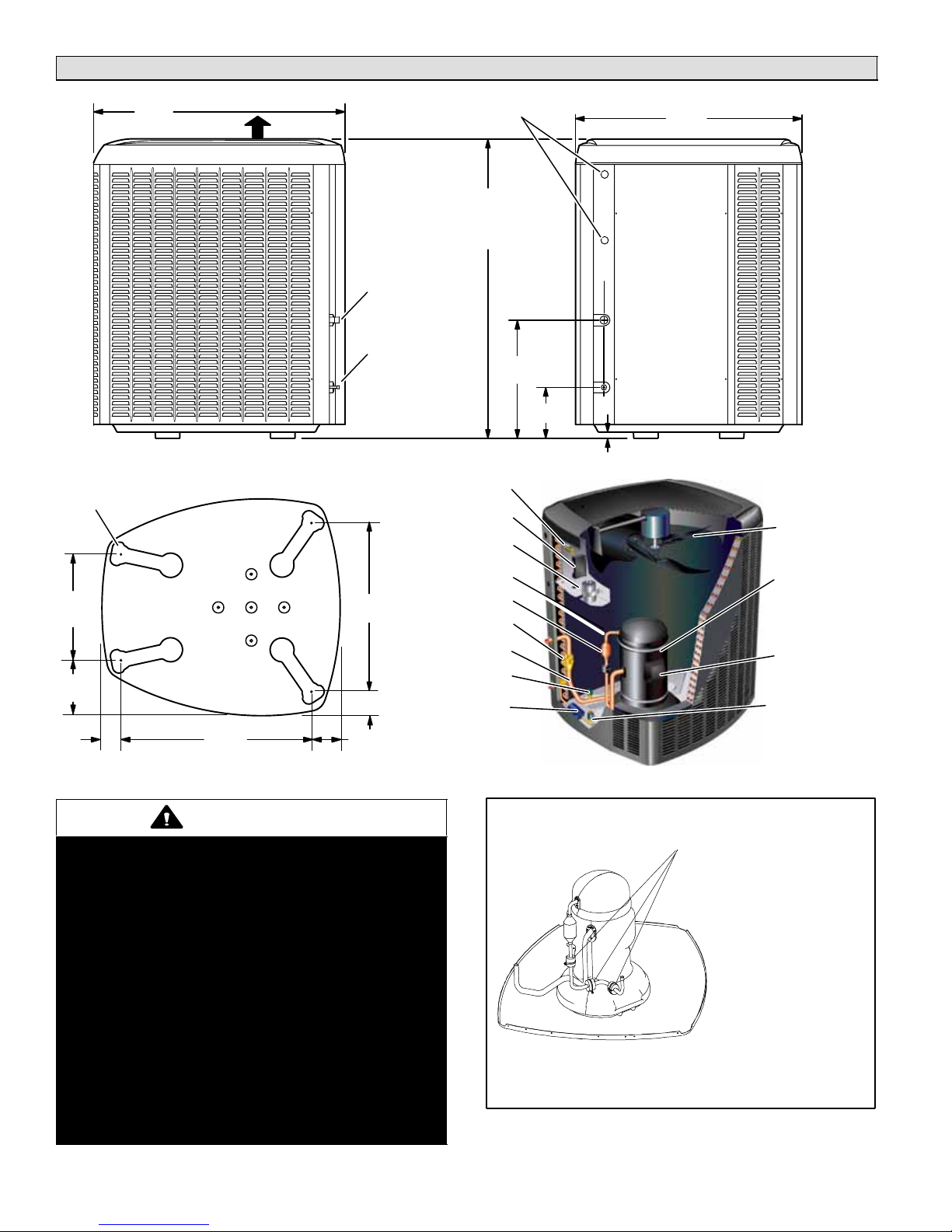
Unit Dimensions − Inches (mm) and Parts Arrangement
39.40"
(1003)
UNIT SUPPORT FEET
16−7/8
(429)
8−3/4
(222)
3−1/8
(79)
DISCHARGE AIR
SIDE VIEW
30−3/4
(781)
SUCTION LINE
INLET
LIQUID LINE
INLET
26−7/8
(683)
3−3/4 (95)
4−5/8
(117)
ELECTRICAL
INLETS
[−024] 41 (1040)
[−030 THROUGH −060]
47 (1194)
CONTACTOR
SYSTEM OPERATION
SUCTION VALVE AND
MONITOR
RUN CAPACITOR
DISCHARGE LINE
MUFFLER
GAUGE PORT
SUCTION LINE
LOW PRESSURE
SWITCH
FILTER DRIER
18.60"
(470)
8.00"
(203)
1 (25)
35.50"
(902)
ACCESS VIEW
OUTDOOR FAN
COMPRESSOR
AND SOUND
REDUCTION
COVER
COMPRESSOR
TERMINAL PLUG
HIGH PRESSURE
SWITCH
BASE WITH ELONGATED LEGS
WARNING
This product and/or the indoor unit it is matched
with may contain fiberglass wool.
Disturbing the insulation during installation,
maintenance, or repair will expose you to fiberglass
wool dust. Breathing this may cause lung cancer.
(Fiberglass wool is known to the State of California
to cause cancer.)
Fiberglass wool may also cause respiratory, skin,
and eye irritation.
To reduce exposure to this substance or for further
information, consult material safety data sheets
available from address shown below, or contact
your supervisor.
Lennox Industries Inc.
P.O. Box 799900
Dallas, TX 75379−9900
506044−01 06/08
Page 2
XC15 PARTS ARRANGEMENT
VIBRATION ISOLATOR SLEEVE
LOCATIONS ON −024, −030 AND
−036.
NOTE: ON THE −042, ALL THREE
VIBRATION ISOLATOR
SLEEVES ARE LOCATED ON
THE HORIZONTAL SECTION OF
THE DISCHARGE LINE.
DO NOT REMOVED THE THREE VIBRATION ISOLATOR SLEEVES (IF
PRESENT) FROM THE COMPRESSOR DISCHARGE LINE
Figure 1. Discharge Line Vibration Isolators
XC15 Outdoor Unit
The XC15 Air Conditioners, which will also be referred to in
this instruction as the outdoor unit, uses HFC−410A
refrigerant. This outdoor unit must be installed with a
matching indoor unit and line set as outlined in the Lennox
XC15 Engineering Handbook.
This outdoor unit is designed for use in systems that use
thermal expansion valve (TXV) refrigerant metering
devices.
General Information
These instructions are intended as a general guide and do
not supersede local codes in any way. Consult authorities
who have jurisdiction before installation.
When servicing or repairing HVAC components, ensure
caps and fasteners are appropriately tightened. Table 1
lists torque values for typical service and repair items.
Table 1. Torque Requirements
Part Recommended Torque
Service valve cap 8 ft.− lb. 11 NM
Sheet metal screws 16 in.− lb. 2 NM
Machine screws #10 28 in.− lb. 3 NM
Compressor bolts 90 in.− lb. 10 NM
Gauge port seal cap 8 ft.− lb. 11 NM
USING MANIFOLD GAUGE SETS
When checking the system charge, only use a manifold
gauge set that features low−loss anti−blow back fittings.
See figure 4 for a typical manifold gauge connection setup.
Manifold gauge sets used with HFC−410A refrigerant
systems must be capable of handling the higher system
operating pressures. The gauges should be rated for use
with pressures of 0 − 800 on the high side and a low side of
30" vacuum to 250 psi with dampened speed to 500 psi.
Gauge hoses must be rated for use at up to 800 psi of
pressure with a 4000 psi burst rating.
OPERATING SERVICE VALVES
The liquid and suction line service valves are used for
removing refrigerant, flushing, leak testing, evacuating,
checking charge and charging.
Each service valve is equipped with a service port which
has a factory−installed valve stem.
IMPORTANT
Only use Allen wrenches of sufficient hardness
(50Rc − Rockwell Harness Scale minimum). Fully
insert the wrench into the valve stem recess.
Service valve stems are factory−torqued (from 9
ft−lbs for small valves, to 25 ft−lbs for large valves) to
prevent refrigerant loss during shipping and
handling. Using an Allen wrench rated at less than
50Rc risks rounding or breaking off the wrench, or
stripping the valve stem recess.
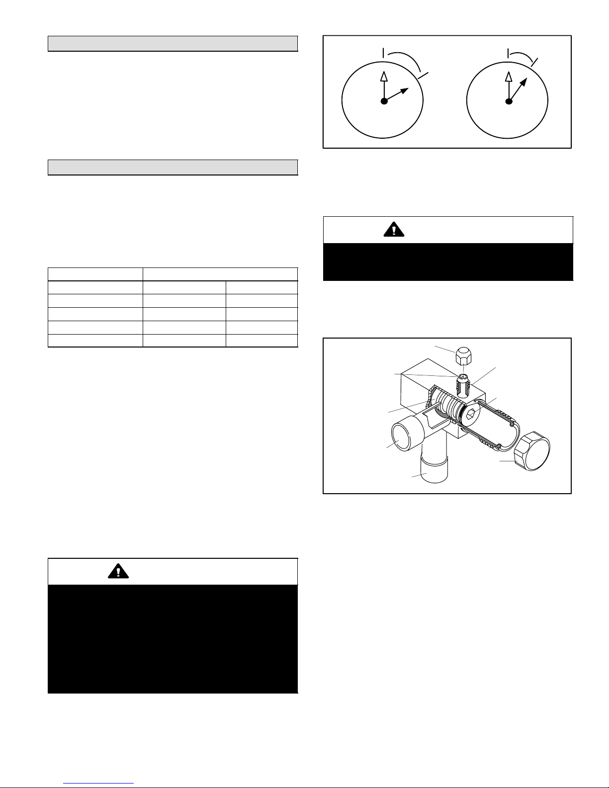
1/12 TURN
12
1
2
3
4
7
5
6
9
10
8
11
1/6 TURN
12
1
2
3
4
7
5
6
11
10
9
8
Figure 2. Cap Tightening Distances
NOTE − A label with specific torque requirements may be
affixed to the stem cap. If the label is present, use the
specified torque.
IMPORTANT
To prevent stripping of the various caps used, the
appropriately sized wrench should be used and
fitted snugly over the cap before tightening.
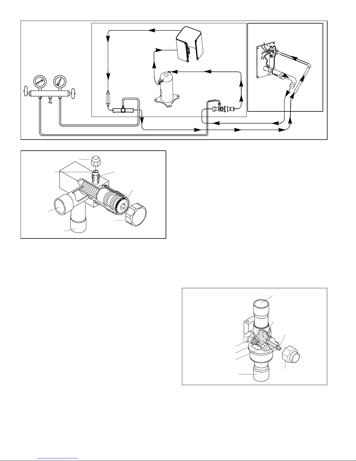
To Access Angle−Type Service Port:
A service port cap protects the service port core from
contamination and serves as the primary leak seal.
SERVICE PORT CAP
STEM CAP
SERVICE PORT
(VALVE STEM SHOWN
CLOSED) INSERT HEX
WRENCH HERE
SERVICE PORT
CLOSED TO BOTH
INDOOR AND
OUTDOOR UNITS
FRONT-SEATED
CORE
VALVE STEM
TO INDOOR
UNIT
TO OUTDOOR UNIT
Figure 3. Angle−Type Service Valve
(Font−Seated Closed)
1. Remove service port cap with an appropriately sized
wrench.
2. Connect gauge to the service port.
3. When testing is completed, replace service port cap and
tighten as follows:
S With Torque Wrench: Finger tighten and then
tighten per table 1.
S Without Torque Wrench: Finger tighten and use an
appropriately sized wrench to turn an additional
1/6 turn clockwise as illustrated in figure 2.
To Open and Close Angle−Type Service Valve:
A valve stem cap protects the valve stem from
contamination and assures a leak−free seal.
Page 3
XC15 SERIES
OUTDOOR UNIT
(Uncased Coil Shown)
LOW
PRESSURE
GAUGE MANIFOLD
PRESSURE
TO
HFC−410A
DRUM
HIGH
FILTER
DRIER
LIQUID LINE
SERVICE VALVE
COMPRESSOR
Figure 4. Typical Manifold Gauge Connection Setup
SERVICE PORT CAP
SERVICE PORT
CORE
OPEN TO BOTH
INDOOR AND
OUTDOOR UNITS
TO INDOOR
UNIT
TO OUTDOOR UNIT
STEM CAP
SERVICE PORT
(VALVE STEM SHOWN OPEN)
INSERT HEX WRENCH HERE
Figure 5. Angle−Type Service Valve
(Back−Seated Opened)
1. Remove stem cap with a wrench.
2. Use a service wrench with a hex−head extension
(3/16" for liquid-line valve sizes and 5/16" for
suction-line valve sizes) to back the stem out
counterclockwise as far as it will go.
3. Replace the stem cap and tighten as follows:
S With Torque Wrench: Tighten finger tight and then
tighten per table 1.
S Without Torque Wrench: Finger tighten and use an
appropriately sized wrench to turn an additional
1/12 turn clockwise as illustrated in figure 2.
To Access Ball−Type Service Port:
A service port cap protects the service port core from
contamination and serves as the primary leak seal.
1. Remove service port cap with an appropriately sized
wrench.
2. Connect gauge to the service port.
3. When testing is completed, replace service port cap and
tighten as follows:
OUTDOOR
COIL
SUCTION LINE
SERVICE VALVE
TXV
S With Torque Wrench: Finger tighten and then
tighten per table 1.
S Without Torque Wrench: Finger tighten and use an
appropriately sized wrench to turn an additional
1/6 turn clockwise as illustrated in figure 2.
To Open and Close Ball−Type Service Valve:
A valve stem cap protects the valve stem from
contamination and assures a leak−free seal.
1. Remove stem cap with a wrench.
2. Use an appropriately sized wrench to open. To open
valve, rotate stem counterclockwise 90°. To close
rotate stem clockwise 90°.
3. Replace the stem cap and tighten as follows:
S With Torque Wrench: Finger tighten and then
tighten per table 1.
S Without Torque Wrench: Finger tighten and use an
appropriately sized to wrench turn an additional
1/12 turn clockwise as illustrated in figure 2.
OPEN TO LINE SET WHEN VALVE IS
CLOSED, TO BOTH LINE SET AND
UNIT WHEN VALVE IS OPEN.
TO OPEN ROTATE STEM
COUNTERCLOCKWISE
90°.
TO CLOSE ROTATE
STEM CLOCKWISE 90°.
SERVICE
PORT
SERVICE
PORT CORE
SERVICE PORT
TO OUTDOOR UNIT
CAP
Figure 6. Ball−Type Service Valve
TO INDOOR UNIT
BALL
(SHOWN
CLOSED)
VALV E
STEM
STEM
CAP
506044−01 06/08
Page 4
Recovering Refrigerant from Existing
System
Remove existing HCFC−22 refrigerant using one of the
following methods:
METHOD 1:
Use this method if the existing outdoor unit is not equipped
with manual shut−off valves, and plan on using existing
HCFC−22 refrigerant to flush the system.
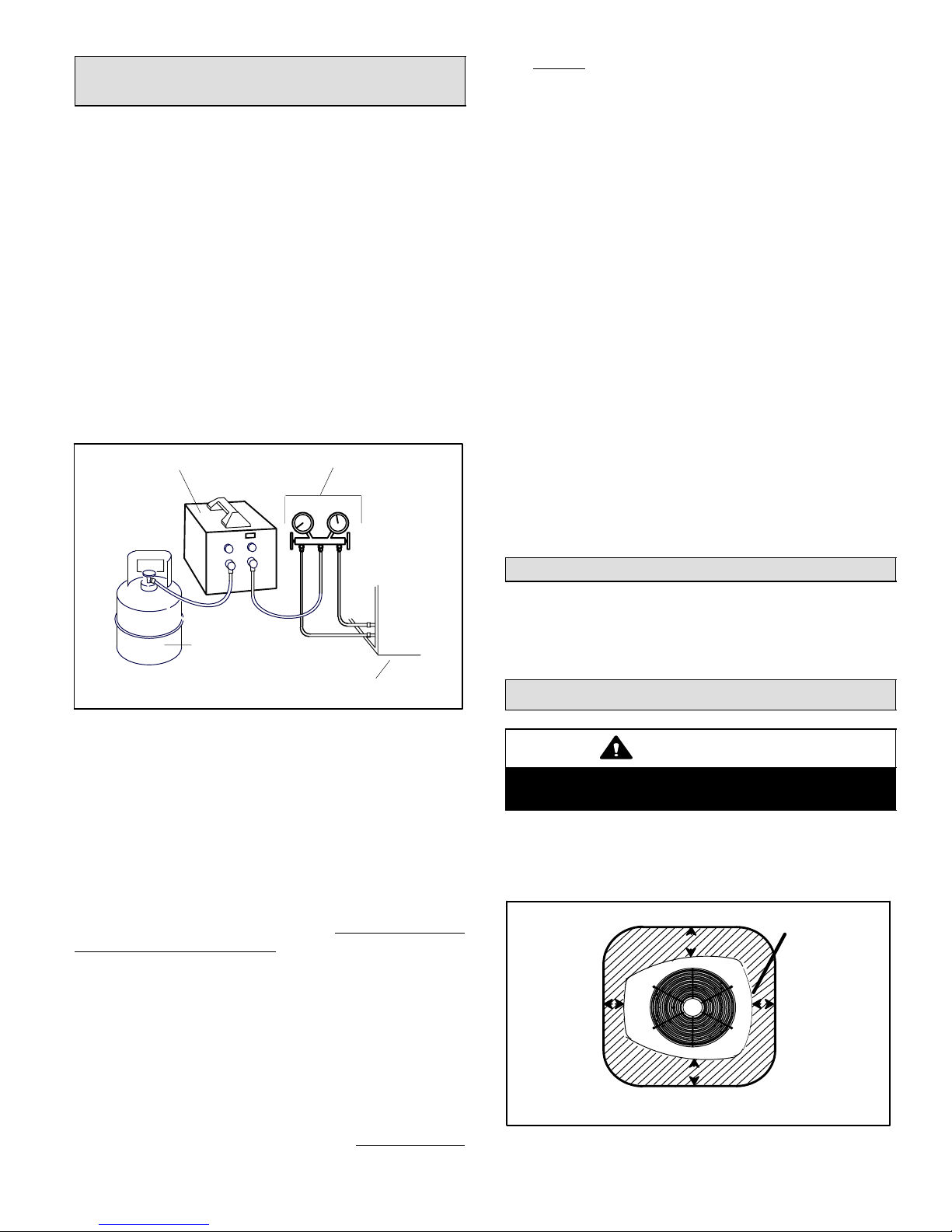
NOTE − Use recovery machine instructions for specific
setup requirements.
Perform the following task:
1. Disconnect all power to the existing outdoor unit.
2. Connect to the existing unit a gauge set, clean
recovery cylinder and a recovery machine. Use the
instructions provided with the recover machine on how
to setup the connections.
3. Remove all HCFC−22 refrigerant from the existing
system. Check gauges after shutdown to confirm that
the entire system is completely void of refrigerant.
RECOVERY MACHINE
MANIFOLD GAUGES
allowed to go into a vacuum. Prolonged operation at
low suction pressures will result in overheating of the
scrolls and permanent damage to the scroll tips, drive
bearings and internal seals).
Once the compressor can not pump down to a lower
pressure due to one of the above system conditions, shut
off the suction valve. Turn OFF the main power to unit and
use a recovery machine to recover any refrigerant left in
the indoor coil and line set.
Perform the following task:
1. Start the existing HCFC−22 system in the cooling
mode and close the liquid line valve.
2. Pump as much of the existing HCFC−22 refrigerant
with the compressor back into the outdoor unit until
you have reached the limitations of the outdoor
system. Turn the outdoor unit main power OFF and
use a recovery machine to remove the remaining
refrigerant in the system.
NOTE − It may be necessary to bypass the low pressure
switches if equipped to ensure complete refrigerant
evacuation.
3. When the low side system pressures reach 0 psig,
close the suction line valve.
4. Check gauges after shutdown to confirm that the
valves are not allowing refrigerant to flow back into the
low side of the system.
CLEAN RECOVERY
CYLINDER
OUTDOOR UNIT
Figure 7. Typical Refrigerant Recovery
(Method 1)
METHOD 2:
Use this method if the existing outdoor unit is equipped
with manual shut−off valves, and plan on using new
HCFC−22 refrigerant to flush the system.
IMPORTANT: Some system configurations may contain
higher than normal refrigerant charge due to either large
internal coil volumes, and/or long line sets. The following
conditions may cause the compressor to stop functioning:
The following devices could prevent full system charge
recovery into the outdoor unit:
S Outdoor unit’s high or low−pressure switches (if
applicable) when tripped can cycled the compressor
OFF.
S Compressor can stop pumping due to tripped internal
pressure relief valve.
S Compressor has internal vacuum protection that is
designed to unload the scrolls (compressor stops
pumping) when the pressure ratio meets a certain
value or when the suction pressure is as high as 20
psig. (Compressor suction pressures should never be
Removing Existing Outdoor Unit
Perform the following task at the existing outdoor unit:
S Disconnect line set at the service valves.
S Disconnect electrical service at the disconnect switch.
S Remove old outdoor unit.
Positioning New Outdoor Unit
CAUTION
In order to avoid injury, take proper precaution when
lifting heavy objects.
See Unit Dimensions on page 2 for sizing mounting slab,
platforms or supports. Refer to figure 8 for mandatory
installation clearance requirements.
CONTROL PANEL
ACCESS LOCATION
*
Page 5
*
*
* SEE NOTES ON NEXT PAGE FOR FURTHER DETAILS.
Figure 8. Installation Clearances
*
XC15 SERIES
NOTES:
S Service clearance of 30 in. (762 mm) must be
maintained on one of the sides adjacent to the control
box.
S Clearance to one of the other three sides must be 36
in. (914 mm)
.
S Clearance to one of the remaining two sides may be
12 in. (305 mm) and the final side may be 6 in. (152
.
mm)
S 48 in. (1219 mm) clearance required on top of unit.
S A clearance of 24 in. (610 mm) must be maintained
between two units.
POSITIONING CONSIDERATIONS
Consider the following when positioning the unit:
BUILDING
STRUCTURE
MOUNTING
SLAB
GROUND LEVEL
Figure 10. Slab Mounting at Ground Level
NOTE − If necessary for stability, anchor unit to slab as
described in Stabilizing Unit on Uneven Surfaces on page
7.
INSTALL UNIT
AWAY FROM
WINDOWS
TWO 90° ELBOWS INSTALLED IN
LINE SET WILL REDUCE LINE SET
VIBRATION.
Figure 9. Outside Unit Placement
S Some localities are adopting sound ordinances based
on the unit’s sound level registered from the adjacent
property, not from the installation property. Install the
unit as far as possible from the property line.
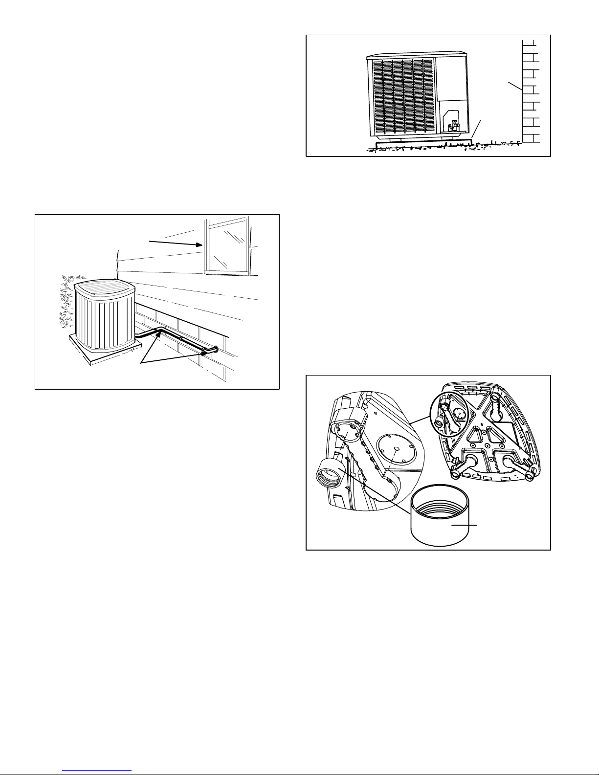
S When possible, do not install the unit directly outside
a window. Glass has a very high level of sound
transmission. For proper placement of unit in relation
to a window see the provided illustration in figure 9.
PLACING OUTDOOR UNIT ON SLAB
When installing unit at grade level, the top of the slab
should be high enough above grade so that water from
higher ground will not collect around the unit. The slab
should have a slope tolerance as described in figure 10.
NOTE − Install unit level or, if on a slope, maintain slope
tolerance of 2 degrees (or 2 inches per 5 feet [50 mm per
1.5 m]) away from building structure.
ELEVATING THE UNIT
Unlike the small−base units which use round support feet,
the larger−base units are outfitted with elongated support
feet as illustrated in figure 11 which uses a similar method
for elevating the unit.
If additional elevation is necessary, raise the unit by
extending the length of the unit support feet. This may be
achieved by using a 2" SCH 40 female threaded adapter.
The specified coupling will fit snuggly into the recessed
portion of the feet. Use additional 2" SCH 40 male threaded
adaptors which can be threaded into the female threaded
adaptors to make additional adjustments to the level of the
unit.
BASE
LEG DETAIL
2" (50.8MM) SCH 40
FEMALE THREADED
ADAPTER
Figure 11. Elevated Slab Mounting using
Feet Extenders (Larger Base Units)
NOTE − Keep the height of extenders short enough to
ensure a sturdy installation. If it is necessary to extend
further, consider a different type of field−fabricated
framework that is sturdy enough for greater heights.
506044−01 06/08
Page 6
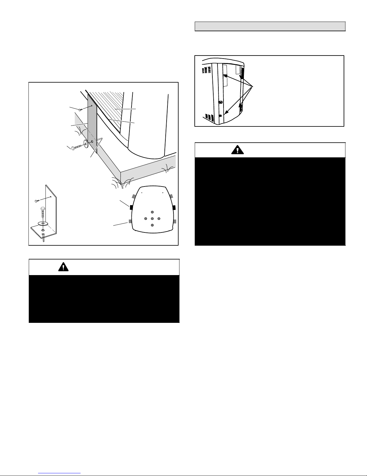
STABILIZING UNIT ON UNEVEN SURFACES
To help stabilize an outdoor unit, some installations may
require strapping the unit to the pad using brackets and
anchors commonly available in the marketplace.
With unit positioned at installation site, remove two side
louvered panels to expose the unit base pan. Install the
brackets as illustrated in figure 12 using conventional
practices; replace the panels after installation is complete.
Slab Side Mounting
#10 1/2" LONG SELF−
DRILLING SHEET
METAL SCREWS
STABILIZING
BRACKET (18 GAUGE
METAL − 2" WIDTH;
HEIGHT AS REQ’D)
#10 1−1/4" LONG
HEX HD SCREW
AND FLATWASHER
COIL
BASE PAN
CORNER POST
Removing and Installing Panels
ACCESS PANEL
Remove and reinstall access panel as shown in figure 13.
REMOVE 4 SCREWS TO REMOVE PANEL
FOR ACCESSING COMPRESSOR AND
CONTROLS.
INSTALL BY POSITIONING PANEL WITH
HOLES ALIGNED; INSTALL SCREWS AND
TIGHTEN.
Figure 13. Access Panel
CAUTION
CONCRETE SLAB − USE PLASTIC
PLASTIC ANCHOR (HOLE DRILL
1/4")PLASTIC SLAB − NO PLASTIC
ANCHOR (HOLE DRILL 1/8")
STABILITY
MINIMUM 1
PER SIDE
Deck Top
Mounting
STABILIZING BRACKET
(18 GAUGE METAL − 2"
WIDTH; HEIGHT AS
REQ’D); BEND TO FORM
RIGHT ANGLE
ONE BRACKET PER SIDE (MIN.); FOR EXTRA STABILITY,
2 BRACKETS PER SIDE, 2" FROM EACH CORNER.
FOR EXTRA
Figure 12. Installing Stabilizer Brackets
IMPORTANT
Unit Stabilizer Bracket Use (field−provided):
Always use stabilizers when unit is raised above the
factory height. (Elevated units could become
unstable in gusty wind conditions).
Stabilizers may be used on factory height units
when mounted on unstable an uneven surface.
ROOF MOUNTING
Install unit at a minimum of four inches above the surface
of the roof. Care must be taken to ensure weight of unit is
properly distributed over roof joists and rafters. Either
redwood or steel supports are recommended.
To prevent personal injury, or damage to panels,
unit or structure, be sure to observe the following:
While installing or servicing this unit, carefully stow
all removed panels out of the way, so that the panels
will not cause injury to personnel, nor cause
damage to objects or structures nearby, nor will the
panels be subjected to damage (e.g., being bent or
scratched).
While handling or stowing the panels, consider any
weather conditions, especially windy conditions,
that may cause panels to be blown around and
battered.
INSTALLING ISOLATION GROMMETS
Locate the isolation grommets (provided). Slide grommets
onto suction and liquid lines. Insert grommets into mullion
to isolate refrigerant lines from sheet metal edges.
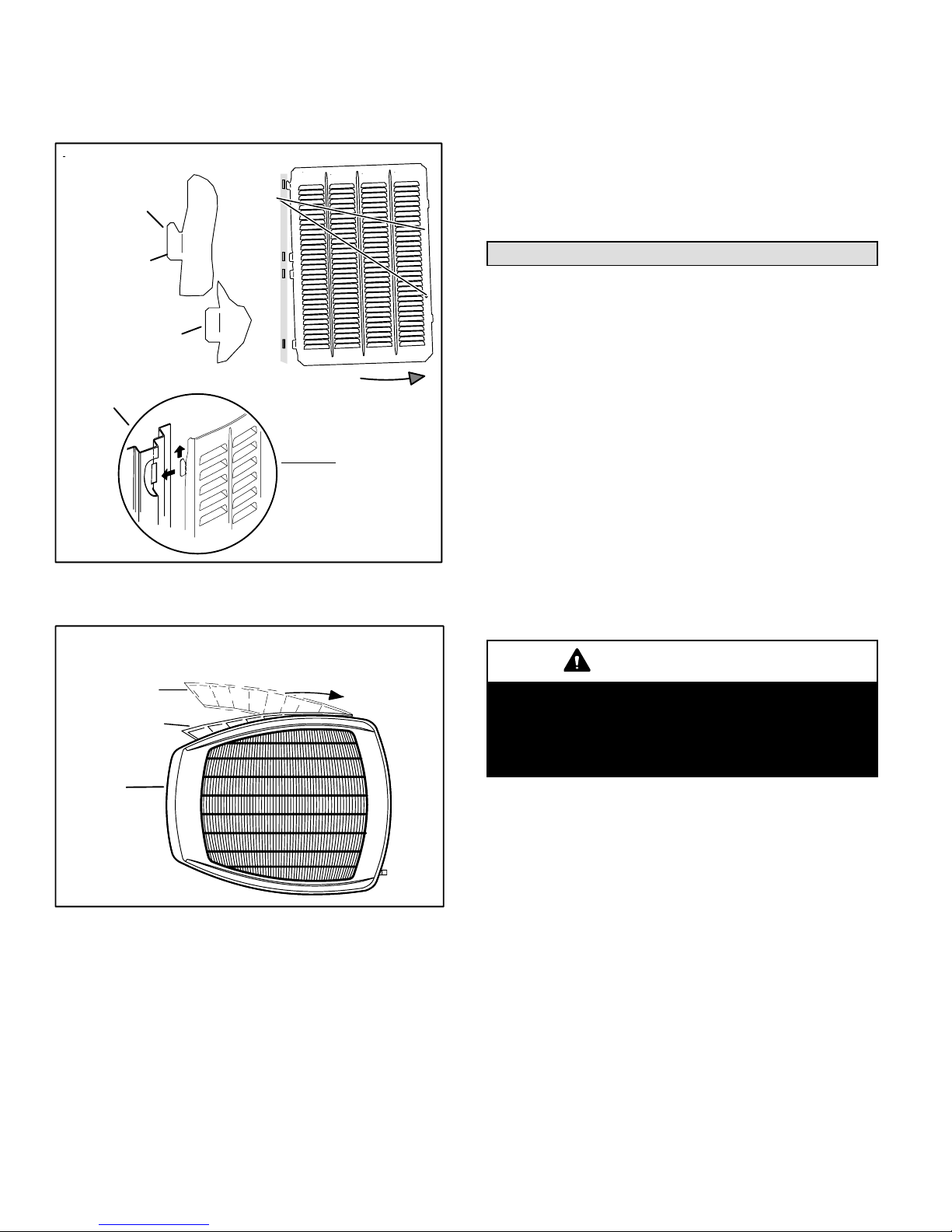
REMOVING PANELS
Remove the louvered panels as follows:
1. Remove two screws, allowing the panel to swing open
slightly as illustrated in figure 14.
NOTE − Hold the panel firmly throughout this procedure
2. Rotate bottom corner of panel away from hinge corner
post until lower three tabs clear the slots as illustrated
in figure 14, detail B.
3. Move panel down until lip of upper tab clears the top
slot in corner post as illustrated in figure 14, detail A.
Page 7
XC15 SERIES
INSTALLING PANEL
Install unit at a minimum of four inches above the surface
of the roof. Care must be taken to ensure weight of unit is
properly distributed over roof joists and rafters.
IPANEL SHOWN SLIGHTLY ROTATED TO ALLOW TOP TAB TO EXIT (OR ENTER) TOP
SLOT FOR REMOVING (OR INSTALLING) PANEL.
SCREW
LIP
HOLES
2. With a continuous motion slightly rotate and guide the
lip of top tab inward as illustrated in figure 14, details
A and C, then upward into the top slot of the hinge
corner post.
3. Rotate panel to vertical to fully engage all tabs.
4. Holding the panel’s hinged side firmly in place, close
the right−hand side of the panel, aligning the screw
holes.
5. When panel is correctly positioned and aligned, insert
the screws and tighten.
DETAIL A
DETAIL B
ROTATE IN THIS DIRECTION; THEN DOWN TO REMOVE PANEL
DETAIL C
IMPORTANT! DO NOT ALLOW
PANELS TO HANG ON UNIT BY TOP
TAB. TAB IS FOR ALIGNMENT AND
NOT DESIGNED TO SUPPORT
WEIGHT OF PANEL.
Figure 14. Removing/Installing Louvered
Panels (Details A, B and C)
MAINTAIN MINIMUM PANEL ANGLE (AS CLOSE TO PARALLEL WITH THE UNIT
AS POSSIBLE) WHILE INSTALLING PANEL.
ANGLE MAY BE
TOO EXTREME
PREFERRED ANGLE
FOR INSTALLATION
DETAIL D
HOLD DOOR FIRMLY TO THE
HINGED B SIDE TO MAINTAIN
FULLY−ENGAGED TABS
Figure 15. Removing/Installing Louvered
Panels (Detail D)
New or Replacement Line Set
This section provides information on installation or
replacement of existing line set. If line set are not being
installed then proceed to Brazing Connections on page 9.
If refrigerant lines are routed through a wall, seal and
isolate the opening so vibration is not transmitted to the
building. Pay close attention to line set isolation during
installation of any HVAC system. When properly isolated
from building structures (walls, ceilings. floors), the
refrigerant lines will not create unnecessary vibration and
subsequent sounds.
REFRIGERANT LINE SET
Field refrigerant piping consists of liquid and suction lines
from the outdoor unit (braze connections) to the indoor unit
coil (flare or sweat connections). Use Lennox L15 (sweat,
non−flare) series line set, or use field−fabricated refrigerant
lines as listed in table 2.
MATCHING WITH NEW OR EXISTING INDOOR COIL
AND LINE SET
IMPORTANT
Matching XC15 with a New Indoor Coil and Line
SetIf installing a new indoor coil and reusing the
existing line set that included a RFCI liquid line
(small bore liquid line used as a metering device)
then you must change to a standard size liquid line.
NOTE − When installing refrigerant lines longer than 50
feet, see the Lennox Refrigerant Piping Design and
Fabrication Guidelines, or contact Lennox Technical
Support Product Applications for assistance. To obtain the
correct information from Lennox, be sure to communicate
the following points:
S Model (XC15) and size of unit (e.g. −060).
Install the louvered panels as follows:
1. Position the panel almost parallel with the unit as
illustrated in figure 15, detail D with the screw side as
close to the unit as possible.
506044−01 06/08
S Line set diameters for the unit being installed as listed
in table 2 and total length of installation.
S Number of elbows and if there is a rise or drop of the
piping.
Page 8
 Loading...