

Page 1
E N G I N E E R I N G D A TA
A I R C O N D I T I O N E R S
XC14
ELITE® Series
R-410A
Bulletin No. 210484
November 2010
Supersedes October 2010
MODEL NUMBER IDENTIFICATION
X C 14 - 036 - 230 - 2
Refrigerant Type
X = R-410A
Unit Type
C = Air Conditioner
Series
SEER up to 16.50
1.5 to 5 Tons
Cooling Capacity - 16,900 to 58,000 Btuh
Minor Revision Number
Voltage
230 = 208/230V-1phase-60hz
Nominal Cooling Capacity
018 = 1.5 tons
024 = 2 tons
030 = 2.5 tons
036 = 3 tons
041 = 3.5 tons
042 = 3.5 tons
047 = 4 tons
048 = 4 tons
060 = 5 tons
Page 2
FEATURES
Contents
AHRI System Matches................................................11
Dimensions ...................................................................9
Electrical Data...............................................................6
Features........................................................................2
Field Wiring ...................................................................8
Installation Clearances .................................................8
Model Number Identication .........................................1
Optional Accessories ....................................................6
Outdoor Sound Data ....................................................8
Specications ...............................................................6
Warranty
Compressor - limited warranty for ten years in
residential installations and ve years in non-residential
installations.
All other covered components - ve years in
residential installations and one year in non-residential
installations.
Refer to Lennox Equipment Limited Warranty certicate
included with unit for specic details.
Applications
SEER up to 16.50.
1.5 through 5 ton.
Single-phase power supply.
Vertical air discharge allows concealment behind shrubs
at grade level or out of sight on a roof.
Matching add-on furnace indoor coils or air handlers
provide a wide range of cooling capacities and
applications. See AHRI Ratings table. See Indoor Coils
and Air Handlers sections for data.
Units shipped completely factory assembled, piped and
wired.
Each unit test operated at the factory ensuring proper
operation. Installer must set air conditioner, connect
refrigerant lines and make electrical connections to
complete job.
G
H
B
C
F
A
D
E
I
Approvals
Certied in Accordance with the USE certication
program, which is based on AHRI Standard 210/240-
2008.
Sound rated in Lennox reverberant sound test room
in Accordance with test conditions included in AHRI
Standard 270-2008.
Tested in the Lennox Research Laboratory
environmental test room. Rated According to U.S.
Department of Energy (DOE) test procedures.
Units and components within bonded for grounding to
meet safety standards for servicing required by UL,
NEC and CEC.
Units are UL listed and CSA certied.
ISO 9001 Registered Manufacturing Quality System.
EnErgy Star® certied units are designed to use less
energy, help save money on utility bills, and help protect
the environment.
For expanded ratings, see www.lennoxdavenet.com
XC14 - 1.5 to 5 Ton Air Conditioner / Page 2
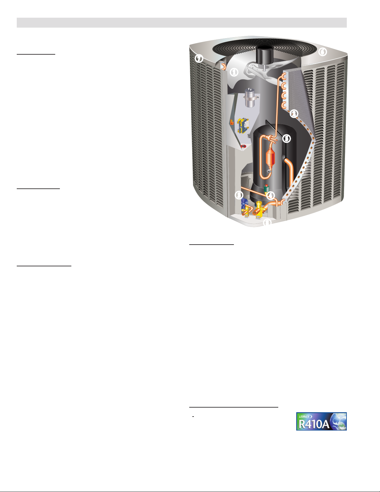
REFRIGERATion SYSTEM
R-410A Refrigerant
Non-chlorine, ozone friendly, R-410A.
Unit pre-charged with refrigerant. See
Specication table.
Page 3
RFCIV METERING SYSTEM
FEATURES
REFRIGERATion SYSTEM (C0NTINUED)
Outdoor Coil Fan
B
Direct drive fan moves large air volumes uniformly
through entire condenser coil for high refrigerant cooling
capacity.
Vertical air discharge minimizes operating sounds and
eliminates damage to lawn and shrubs.
Fan motor has sleeve bearings and is inherently
protected.
Motor totally enclosed for maximum protection from
weather, dust and corrosion.
Fan guard constructed of corrosion-resistant PVC
(polyvinyl chloride) coated steel.
Fan service access accomplished by removal of fan
guard.
Copper Tube/Enhanced Fin Coil
C
Lennox designed and fabricated coil.
Ripple-edged aluminum ns.
Copper tube construction.
Lanced ns provide maximum exposure of n surface to
air stream resulting in excellent heat transfer.
Fin collars grip tubing for maximum contact area.
Flared shoulder tubing connections/silver soldering
construction.
Coil is factory tested under high pressure to ensure
leakproof construction.
Entire coil is accessible for cleaning.
Refrigerant Flow Control
Units applicable to expansion valve systems or RFC
systems when matched with specic evaporator coils.
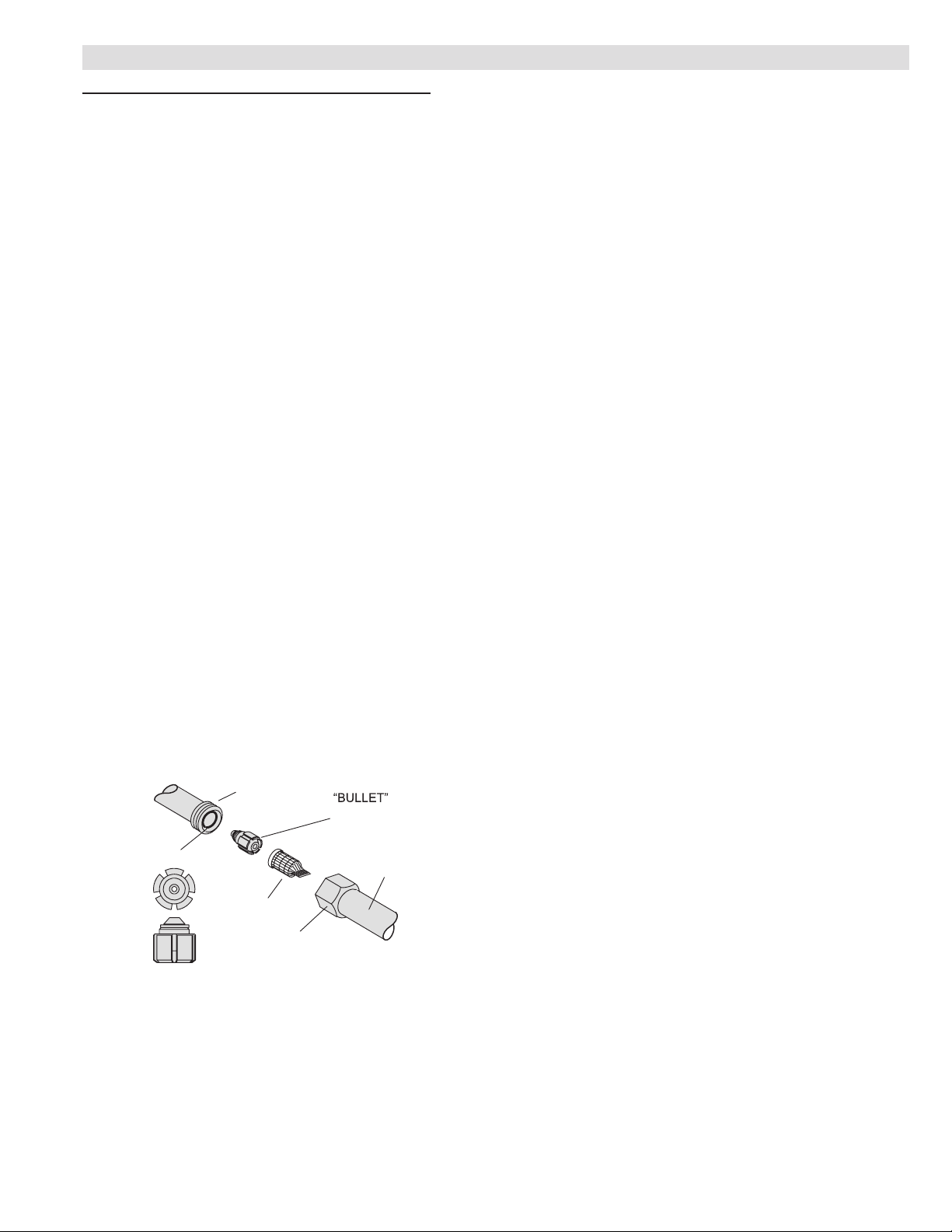
RFCIV METERING SYSTEM
ORIFICE BODY
(On Coil)
O−RING
LIQUID
LINE SCREEN
SEAL
NUT
RFCIV
ORIFICE
LIQUID
LINE
SWEAT
CONNECTION
High Capacity Liquid Line Drier
D
Furnished with unit for eld installation.
Approved for use with R-410A systems.
Traps any moisture or dirt that could contaminate the
refrigerant system.
High Pressure Switch
E
Shuts off unit if abnormal operating conditions cause the
discharge pressure to rise above setting.
Protects compressor from excessive condensing
pressure.
Manual reset.
OPTIONS
Expansion Valve Kits
Must be ordered extra and eld installed on certain
indoor units.
See TXV/Orice Usage table.
Chatleff-style ttings.
Freezestat
Installs on or near the vapor line of the indoor coil or on
the suction line.
Senses suction line temperature and cycles the
compressor off when suction line temperature falls
below it’s setpoint.
Opens at 29°F and closes at 58°F.
Loss of Charge Switch Kit
Helps protect the compressor from damage due low
refrigerant charge conditions.
SPST, normally-closed switch, automatic reset switch
mounted on suction line.
Refrigerant Line Kits
Refrigerant lines (suction & liquid) are shipped
refrigeration clean.
Lines are cleaned, dried, pressurized and sealed at
factory.
Suction line fully insulated.
Lines are stubbed at both ends.
Not available for -060 models and must be eld
fabricated.
RFCIV:
Accurately meters refrigerant in system.
Refrigerant control is accomplished by exact sizing of
refrigerant metering orice.
The principle involves matching indoor coil with proper
bore size of orice in metering device.
Equalizes pressure shortly after compressor stops, unit
starts unloaded, eliminating need for additional controls.
Furnished with air conditioner.
XC14 - 1.5 to 5 Ton Air Conditioner / Page 3
Page 4
FEATURES
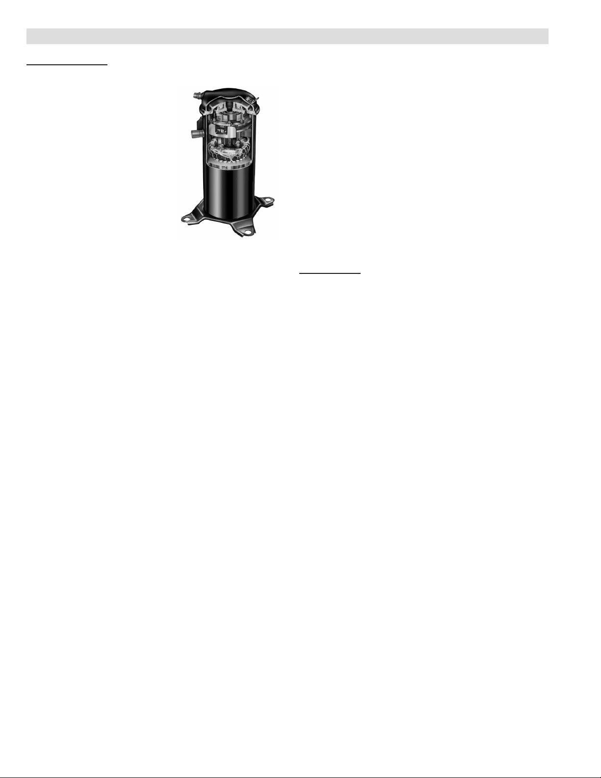
COMPRESSOR
Scroll Compressor
F
Compressor features high
efciency with uniform suction
ow, constant discharge ow and
high volumetric efciency and
quiet operation.
Compressor consists of two
involute spiral scrolls matched
together to generate a series of
crescent shaped gas pockets
between them.
During compression, one scroll
remains stationary while the other
scroll orbits around it.
Gas is drawn into the outer pocket, the pocket is sealed
as the scroll rotates.
As the spiral movement continues, gas pockets are
pushed to the center of the scrolls. Volume between the
pockets is simultaneously reduced.
When pocket reaches the center, gas is now at high
pressure and is forced out of a port located in the center
of the xed scrolls.
During compression, several pockets are compressed
simultaneously resulting in a smooth continuous
compression cycle.
Continuous ank contact, maintained by centrifugal
force, minimizes gas leakage and maximizes efciency.
Scroll compressor is tolerant to the effects of slugging
and contaminants. If this occurs, scrolls separate,
allowing liquid or contaminants to be worked toward the
center and discharged.
Low gas pulses during compression reduces
operational sound levels.
Compressor motor is internally protected from
excessive current and temperature.
Compressor is installed in the unit on specially
formulated, resilient rubber base for improved sound
dampening and vibration-free operation resulting in
quieter operating sound levels. See Outdoor Sound
Data table for details.
Compressor Crankcase Heater (048 & 060 Models)
Protects against refrigerant migration that can occur
during low ambient operation.
Factory Installed
Compressor Sound Dampening System
A polyethylene compressor cover containing a 2 inch
thick batt of berglass insulation for better sound
dampening.
All open edges are sealed with a one-inch wide hook
and loop fastening tape.
OPTIONS
Compressor Crankcase Heater (018 thru 042
models)
Protects against refrigerant migration that can occur
during low ambient operation.
Compressor Hard Start Kit
Single-phase units are equipped with a PSC
compressor motor. This type of motor normally doesn’t
need a potential relay and start capacitor.
In conditions such as low voltage, this kit may be
required to increase the compressor starting torque.
Compressor Low Ambient Cut-Off
Non-adjustable switch (low ambient cut-out) prevents
compressor operation when outdoor temperature is
below 35°F.
CONTROLS
OPTIONS
Indoor Blower Off Delay Relay
Delays the indoor blower-off time during the cooling
cycle.
See AHRI System Matches for usage.
Low Ambient Kit
Air conditioners operate satisfactorily down to 45°F
outdoor air temperature without any additional controls.
Low Ambient Control Kit can be eld installed, allowing
unit operation down to 30°F.
Freezestat should be installed on compressors
equipped with a low ambient kit.
A compressor lock-out thermostat should be added to
terminate compressor operation below recommended
operation conditions
Thermostat
Thermostat not furnished with unit. See Thermostat
bulletins in Controls Section and Lennox Price Book.
Compressor Timed-Off Control
Kit prevents compressor short-cycling and allows time
for suction and discharge pressure to equalize.
Permits compressor start-up in an unloaded condition.
Automatic reset with 5 minute delay between
compressor shut-off and start-up.
XC14 - 1.5 to 5 Ton Air Conditioner / Page 4
Page 5

FEATURES
CABINET
Heavy-gauge steel construction
G
Pre-painted cabinet nish.
Painted base section.
Control box is conveniently located with all controls
factory wired.
Corner patch plate allows access to compressor
components.
Drainage holes are provided in base section for
moisture removal.
High density polyethylene unit support feet raise the
unit off of the mounting surface, away from damaging
moisture.
SmartHinge™ Louvered Coil Protection
H
Steel louvered panels provides
complete coil protection.
Panels are hinged to allow easy
cleaning and servicing of coils.
Panels may be completely
removed.
Interlocking tabs and slots
assure tight t on cabinet.
Refrigerant Line Connections, Electrical Inlets and
I
Service Valves
Suction and liquid lines are located on corner of unit
cabinet and are made with sweat connections.
See dimension drawing.
Fully serviceable brass service valves prevent corrosion
and provide access to refrigerant system. Suction valve
can be fully shut off, while liquid valve may be front
seated to manage refrigerant charge while servicing
system.
Refrigerant line connections and eld wiring inlets are
located in one central area of the cabinet.
See dimension drawing.
XC14 - 1.5 to 5 Ton Air Conditioner / Page 5
Page 6
SPECIFICATIONS
General
Data
Connections
(sweat)
Refrigerant
Outdoor
Coil
Liquid line (o.d.) - in. 3/8 3/8 3/8 3/8
Suction line (o.d.) - in. 3/4 3/4 3/4 7/8
1
R-410A charge furnished 5 lbs. 11 oz. 6 lbs. 8 oz. 6 lbs. 11 oz. 6 lbs. 11 oz.
Net face area - sq. ft. 13.22 18.67 21.00 21.00
Tube diameter - in. 5/16 5/16 5/16 5/16
Outdoor
Fan
Shipping Data - lbs. 1 pkg. 163 203 215 217
ELECTRICAL DATA
Line voltage data - 60hz 208/230V-1ph 208/230V-1ph 208/230V-1ph 208/230V-1ph
2
Maximum overcurrent protection (amps) 25 30 30 30
3
Minimum circuit ampacity 15.7 17.9 17.2 18.7
Compressor Rated load amps 9.0 13.4 12.9 14.1
Locked rotor amps 48 58 64 77
Outdoor Fan Motor Full load amps 0.7 1.1 1.1 1.1
Locked rotor amps 1.4 2.1 2.1 2.1
OPTIONAL ACCESSORIES - MUST BE ORDERED EXTRA
Compressor Hard Start Kit 88M91
Compressor Low Ambient Cut-Off 45F08
Compressor Time-Off Control 47J27
Freezestat 3/8 in. tubing 93G35
5/8 in. tubing 50A93
Low Ambient Kit 34M72
Refrigerant Line
Sets
L15-41-20 L15-41-40
L15-41-30 L15-41-50
Indoor Blower Off Delay Relay 58M81
NOTE - Extremes of operating range are plus 10% and minus 5% of line voltage.
1
Refrigerant charge sufcient for 15 ft. length of refrigerant lines.
2
HACR type breaker or fuse.
3
Refer to National or Canadian Electrical Code manual to determine wire, fuse and disconnect size requirements.
Model No. XC14-018 XC14-024 XC14-030 XC14-036
Nominal Tonnage 1.5 2 2.5 3
No. of rows 1 1 1 1
Fins per inch 26 26 26 26
Diameter - in. 18 22 22 22
No. of blades 3 3 3 3
Motor hp 1/10 1/6 1/6 1/6
Cfm 2270 3160 3160 3160
Rpm 1050 850 850 850
Watts 165 215 215 215
Power factor 0.96 0.97 0.98 0.98
XC14 - 1.5 to 5 Ton Air Conditioner / Page 6
Page 7
SPECIFICATIONS
General
Data
Connections
(sweat)
Refrigerant
Outdoor
Net face area - sq. ft. Outer coil 21 16.33 22 21.00 22.00
Liquid line (o.d.) - in. 3/8 3/8 3/8 3/8 3/8
Suction line (o.d.) - in. 7/8 7/8 7/8 7/8 1-1/8
1
R-410A charge furnished 10 lbs. 1 oz. 8 lbs. 10 oz. 11 lbs. 3 oz. 10 lbs. 0 oz. 12 lbs. 0 oz.
Coil
Tube diameter - in. 5/16 5/16 5/16 5/16 5/16
Outdoor
Fan
Shipping Data - lbs. 1 pkg. 253 243 284 272 290
ELECTRICAL DATA
Line voltage data - 60hz 208/230V 208/230V-1ph 208/230V 208/230V-1ph 208/230V-1ph
2
Maximum overcurrent protection (amps) 35 40 45 50 60
3
Minimum circuit ampacity 22.8 24.1 26.7 29.0 34.8
Compressor Rated load amps 16.7 17.9 19.9 21.8 26.4
Locked rotor amps 79 112 109 117 134
Outdoor Fan
Motor
Locked rotor amps 3.1 3.1 2.9 3.1 2.9
OPTIONAL ACCESSORIES - MUST BE ORDERED EXTRA
Compressor Hard Start Kit 88M91
Compressor Low Ambient Cut-Off 45F08
Compressor Time-Off Control 47J27
Freezestat 3/8 in. tubing 93G35
5/8 in. tubing 50A93
Low Ambient Kit 34M72
Refrigerant
L15-65-40 L15-65-40
Line Sets
Indoor Blower Off Delay Relay 58M81
NOTE - Extremes of operating range are plus 10% and minus 5% of line voltage.
1
Refrigerant charge sufcient for 15 ft. length of refrigerant lines.
2
HACR type breaker or fuse.
3
Refer to National or Canadian Electrical Code manual to determine wire, fuse and disconnect size requirements.
Model No. XC14-041 XC14-042 XC14-047 XC14-048 XC14-060
Nominal Tonnage 3.5 3.5 4 4 5
Inner coil 20.25 15.71 21.33 20.25 21.33
No. of rows 2 2 2 2 2
Fins per inch 22 22 22 22 22
Diameter - in. 22 22 26 22 26
No. of blades 4 4 4 4 4
Motor hp 1/4 1/4 1/3 1/4 1/3
Cfm 3600 3500 4400 3600 4400
Rpm 825 825 825 825 825
Watts 310 310 310 310 310
Power factor 0.97 0.94 0.97 0.95 0.98
Full load amps 1.7 1.7 1.8 1.7 1.8
L15-65-50
Field Fabricate
XC14 - 1.5 to 5 Ton Air Conditioner / Page 7
Page 8

OUTDOOR SOUND DATA
Octave Band Sound Power Levels dBA, re 10-12 Watts
Center Frequency - HZ
1
Unit
Model No.
125 250 500 1000 2000 4000 8000
XC14-018 52.0 59.5 64.5 65.5 60.5 54.5 45.5 71
XC14-024 55.0 60.0 66.0 66.0 62.5 57.5 47.5 71
XC14-030 55.0 62.0 65.5 66.5 60.0 52.5 45.0 71
XC14-036 53.0 61.0 64.5 65.0 59.5 53.5 48.5 70
XC14-041 56.5 62.0 68.0 68.5 63.5 56.5 49.5 73
XC14-042 58.5 64.0 68.5 68.5 63.5 56.5 50.5 73
XC14-047 59.5 62.5 67.5 66.0 63.0 57.5 51.5 73
XC14-048 56.5 62.0 68.0 68.5 63.5 56.5 49.5 73
XC14-060 59.5 62.5 67.5 66.0 63.0 57.5 51.5 73
NOTE - the octave sound power data does not include tonal correction.
1
Tested according to AHRI Standard 270-2008 test conditions.
FIELD WIRING
1
Sound
Rating
Number
(dB)
DISCONNECT
SWITCH
(By Others)
THERMOSTAT
(Optional)
DISCONNECT
SWITCH
(By Others)
A
B
D
C
LENNOX
AIR
CONDITIONER
LENNOX
HEATING UNIT
OR
AIR HANDLER
UNIT
INSTALLATION CLEARANCES - INCHES (MM)
See NOTES
NOTES:
Service clearance of 30 in. (762 mm) must be maintained on one
of the sides adjacent to the control box.
A - Two Wire Power (not furnished)
B - Two Power (not furnished). See Electrical Data
C - Four Wire Low Voltage (not furnished). 18 ga. minimum
D - Five Wire Low Voltage (not furnished). 18 ga. minimum
All wiring must conform to NEC or CEC and local electrical
codes.
See
NOTES
See NOTES
XC14 - 1.5 to 5 Ton Air Conditioner / Page 8
See
NOTES
Control
Box
Clearance to one of the other three sides must be 36 in. (914 mm)
Clearance to one of the remaining two sides may be 12 in. (305
mm) and the final side may be 6 in. (152 mm).
A clearance of 24 in. (610 mm) must be maintained between two
units.
48 in. (1219 mm) clearance required on top of unit.
Page 9
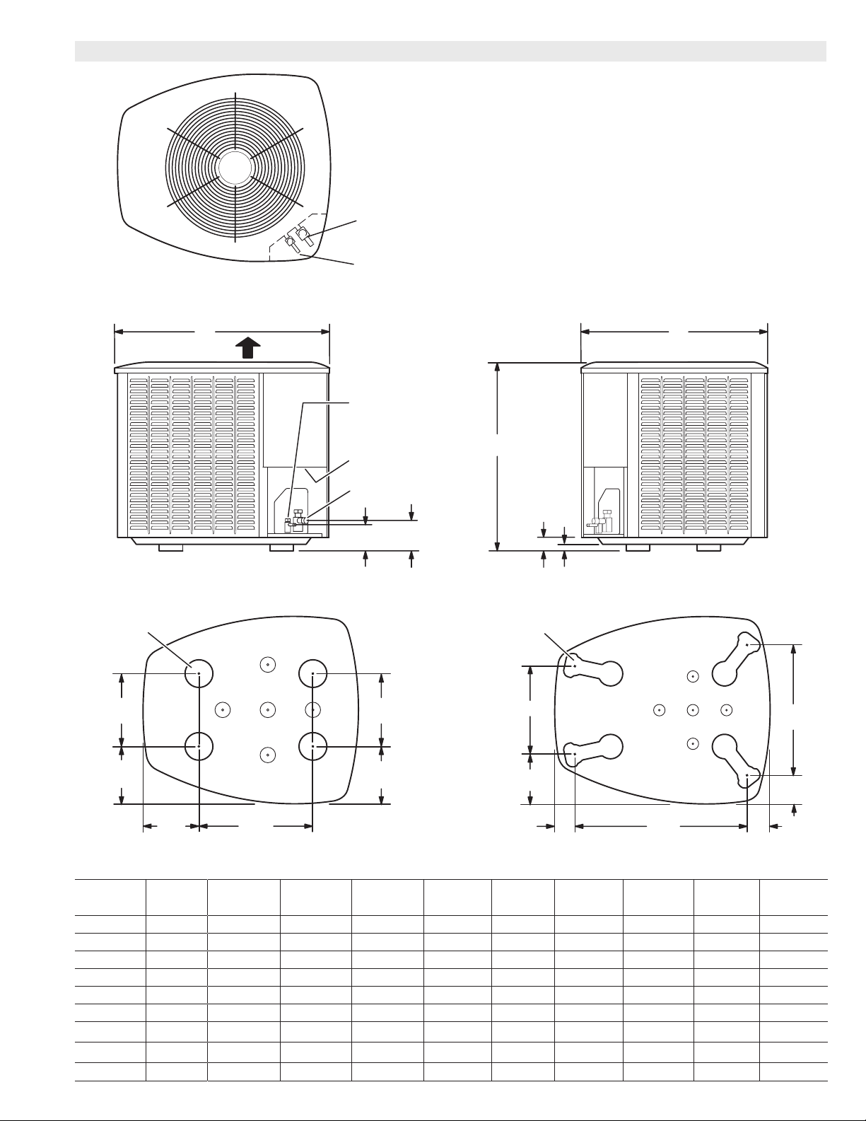
DIMENSIONS - INCHES (MM)
TOP VIEW
DISCHARGE AIR
SUCTION LINE
CONNECTION
LIQUID LINE
CONNECTION
BC
LIQUID LINE
CONNECTION
UNIT SUPPORT
FEET
8−1/2
(216)
8−3/4
(222)
5−1/2
(140)
4−1/4(108)
SIDE VIEW
13−1/2
(343)
XC14-018 BASE SECTION
ELECTRICAL
INLETS
SUCTION LINE
CONNECTION
4−3/4
(121)
9−1/2
(241)
8−1/4
(210)
A
2 (51)
UNIT SUPPORT
FEET
D
E
1 (25)
F
END VIEW
G
H
XC14-024 TO -060 BASE SECTION
K
J
Model No.
A B C D E F G H J K
in. mm in. mm in. mm in. mm in. mm in. mm in. mm in. mm in. mm in. mm
XC14-018 31 787 27 686 28 711 - - - - - - - - - - - - - - - - - - - - - - - - - - - - - - - - - - - - - - - - - XC14-024 35 889 30-1/2 775 35 889 13-7/8 352 7-3/4 197 3-1/4 83 27-1/8 689 3-5/8 92 4-1/2 114 20-5/8 524
XC14-030 39 991 30-1/2 775 35 889 13-7/8 352 7-3/4 197 3-1/4 83 27-1/8 689 3-5/8 92 4-1/2 114 20-5/8 524
XC14-036 39 991 30-1/2 775 35 889 13-7/8 352 7-3/4 197 3-1/4 83 27-1/8 689 3-5/8 92 4-1/2 114 20-5/8 524
XC14-041 39 991 30-1/2 775 35 889 13-7/8 352 7-3/4 197 3-1/4 83 27-1/8 689 3-5/8 92 4-1/2 114 20-5/8 524
XC14-042 31 787 30-1/2 775 35 889 13-7/8 352 7-3/4 197 3-1/4 83 27-1/8 689 3-5/8 92 4-1/2 114 20-5/8 524
XC14-047 35 889 35-1/2 902 39-1/2 1003 16-7/8 429 8-3/4 222 3-1/8 79 30-3/4 781 4-5/8 117 3-3/4 95 26-7/8 683
XC14-048 39 991 30-1/2 775 35 889 13-7/8 352 7-3/4 197 3-1/4 83 27-1/8 689 3-5/8 92 4-1/2 114 20-5/8 524
XC14-060 35 889 35-1/2 902 39-1/2 1003 16-7/8 429 8-3/4 222 3-1/8 79 30-3/4 781 4-5/8 117 3-3/4 95 26-7/8 683
XC14 - 1.5 to 5 Ton Air Conditioner / Page 9
Page 10
TXV/ORIFICE USAGE
Model No. Refrigerant Metering
Orice (RFC)
Order No. Orice Size
XC14-018 97M74 0.053 37L51
XC14-024 97M75 0.057 37L51
XC14-030 10W99 0.065 37L51
XC14-036 11W02 0.071 39L72
XC14-041 97M77 0.074 91M02
XC14-042 97M78 0.076 39L72
XC14-047 10W86 0.080 91M02
XC14-048 11W07 0.083 91M02
XC14-060 11W11 0.093 91M02
CX34 upow coils and all Lennox air handlers (except CB26UH “R”) are
shipped with a factory installed TXV. In most cases, no change out of the valve
is needed.
If a change out is required it will be listed in the “TXV SUBSTITUTIONS” table.
The correct TXV must be ordered and eld installed. C33 coils and all horizontal and downow coils are shipped without a TXV. The TXV must be ordered
and eld installed. .
Thermal
Expansion
Valve (TXV)
MOST POPULAR MATCHES
Outdoor Unit
Model No.
XC14-018 CX34-25
XC14-024 CX34-31
XC14-030 CX34-31
XC14-036 CX34-38
XC14-041 CX34-49
XC14-042 CX34-49
XC14-047 CX34-62C
XC14-048 CX34-62C
XC14-060 CX34-62C
Indoor Unit
Model No
*tXV SUBSTITUTIONS
Indoor Coils/Air Handlers with factory installed expansion
valves that require eld replacement
Model No. Indoor Coil or Air
Handler
XC14-030 CBX27UH-036 37L51
XC14-036 CX34-31 39L72
XC14-036 CX34-36 39L72
XC14-036 CX34-38 39L72
XC14-036 CX34-49 39L72
XC14-036 CX34-50/60 39L72
XC14-036 CBX32M-030 39L72
XC14-036 CBX32M-036 39L72
XC14-036 CBX32M-042 39L72
XC14-036 CBX32M-048 39L72
XC14-036 CBX32MV-036 39L72
XC14-036 CBX32MV-048 39L72
XC14-036 CBX40UHV-036 39L72
XC14-036 CBX40UHV-048 39L72
XC14-042 CX34-36 39L72
XC14-042 CX34-38 39L72
XC14-042 CBX27UH-048 39L72
XC14-042 CBX32M-036 39L72
XC14-042 CBX32M-042 39L72
XC14-042 CBX32M-048 39L72
XC14-042 CBX32MV-048 39L72
XC14-042 CBX40UHV-048 39L72
XC14-048 CX34-43 91M02
XC14-048 CX34-44/48 91M02
* CX34 coils and all air handlers (except CB26UH “R”) - the factory installed
expansion valve must be replaced with the expansion valve listed (ordered
separately). If the combination is not listed above, the factory installed TXV is
used.
C33 and CH33 coils and CB26UH “R” air handlers - use the RFC shipped with
the outdoor unit or replace the factory installed RFC with the expansion valve
listed in the Thermal Expansion Valves Table.
CR33 and CH23 - use the RFC shipped with the outdoor unit or use the expansion valve listed in the Thermal Expansion Valves Table.
Order No.
XC14 - 1.5 to 5 Ton Air Conditioner / Page 10
Page 11

AHRI SYSTEM MATCHES
NOTE - For the latest up-to-date system matches please visit the AHRI web site at http://www.ahridirectory.org
Model
No.
XC14-018-230 RFC 18,100 13.20 11.70 C33-19 1236140
XC14-018-230 RFC 18,300 13.50 11.70 C33-25 1236139
XC14-018-230 RFC 18,500 13.70 12.00 C33-31 1236141
XC14-018-230 RFC 18,000 13.00 11.70 CH33-19 1236145
XC14-018-230 RFC 18,000 13.00 11.70 CH33-24/30 1236148
XC14-018-230 RFC 18,300 13.50 11.70 CH33-25A 1236146
XC14-018-230 RFC 18,200 13.20 11.70 CH33-25B 1236147
XC14-018-230 RFC 18,200 13.50 11.70 CH33-36 1236149
XC14-018-230 RFC 17,800 13.00 11.50 CR33-18 1236142
XC14-018-230 RFC 18,200 13.20 11.70 CR33-24 1236144
XC14-018-230 RFC 18,400 13.70 11.70 CR33-30/36 1236143
XC14-018-230 TXV 18,200 13.95 11.70 C33-19 3009822
XC14-018-230 TXV 17,700 13.20 11.20 C33-24 3009823
XC14-018-230 TXV 18,500 14.20 12.00 C33-25 3009824
XC14-018-230 TXV 18,000 13.55 11.40 C33-30 3009825
XC14-018-230 TXV 18,700 14.20 12.00 C33-31 3009826
XC14-018-230 TXV 18,400 14.35 12.05 CB26UH-018 3009827
XC14-018-230 TXV 18,700 14.35 12.05 CB26UH-024 3009828
XC14-018-230 TXV 18,400 14.00 12.00 CBX26UH-018 3009834
XC14-018-230 TXV 19,000 16.20 13.50 CBX27UH-018 3009835
XC14-018-230 TXV 18,400 14.20 11.70 CBX32M-018/024 3009836
XC14-018-230 TXV 19,100 15.00 12.50 CBX32M-030 3009837
XC14-018-230 TXV 18,700 15.20 12.70 CBX32MV-018/024 3009838
XC14-018-230 TXV 18,800 15.50 12.70 CBX32MV-024/030 3009839
XC14-018-230 TXV 18,700 15.20 12.70 CBX40UHV-024 3291605
XC14-018-230 TXV 18,800 15.50 12.70 CBX40UHV-030 3291625
XC14-018-230 TXV 18,100 13.50 11.50 CH33-19 3009840
XC14-018-230 TXV 18,100 13.50 11.50 CH33-24/30 3009841
XC14-018-230 TXV 18,600 14.20 12.00 CH33-25 3009842
XC14-018-230 TXV 18,400 14.00 11.50 CH33-25B 3009843
XC14-018-230 TXV 18,400 14.00 11.50 CH33-36 3009844
XC14-018-230 TXV 18,000 13.50 11.50 CR33-18 3009845
XC14-018-230 TXV 18,300 13.50 11.50 CR33-24 3009846
XC14-018-230 TXV 18,700 14.20 12.00 CR33-30/36 3009847
XC14-018-230 TXV 17,700 13.00 11.00 CX34-18/24 3009848
XC14-018-230 TXV 18,200 14.00 11.70 CX34-19 3009849
XC14-018-230 TXV 18,500 14.20 12.00 CX34-25 3009850
XC14-018-230 TXV 18,000 13.50 11.00 CX34-30 3009851
XC14-018-230 TXV 18,700 14.20 12.00 CX34-31 3009852
XC14-024-230 RFC 23,400 13.50 11.50 C33-19 3130410
XC14-024-230 RFC 23,400 14.20 12.50 C33-24 G61MPV-36B-045 3130425
XC14-024-230 RFC 23,400 14.20 12.50 C33-24 G61MPV-36B-070 3130426
XC14-024-230 RFC 23,400 14.20 12.50 C33-24 G61MPV-36B-071 3130466
XC14-024-230 RFC 24,400 15.50 13.20 C33-25 G61MPV-36B-045 3130429
XC14-024-230 RFC 24,400 15.70 13.20 C33-25 G61MPV-36B-070 3130430
XC14-024-230 RFC 24,400 15.70 13.20 C33-25 G61MPV-36B-071 3130467
XC14-024-230 RFC 23,800 13.70 11.70 C33-25 3130408
XC14-024-230 RFC 23,800 14.50 12.70 C33-30 G61MPV-36B-045 3130433
XC14-024-230 RFC 23,800 14.50 12.70 C33-30 G61MPV-36B-070 3130434
XC14-024-230 RFC 23,800 14.50 12.70 C33-30 G61MPV-36B-071 3130468
XC14-024-230 RFC 23,200 13.00 11.50 C33-30 3130409
XC14-024-230 RFC 24,800 15.70 13.20 C33-31 G61MPV-36B-045 3130437
XC14-024-230 RFC 24,800 15.70 13.20 C33-31 G61MPV-36B-070 3130438
XC14-024-230 RFC 24,800 15.70 13.20 C33-31 G61MPV-36B-071 3130469
XC14-024-230 RFC 24,200 14.00 12.00 C33-31 3130407
XC14-024-230 RFC 24,200 15.20 13.00 C33-36 G61MPV-36B-045 3130441
XC14-024-230 RFC 24,200 15.50 13.00 C33-36 G61MPV-36B-070 3130442
XC14-024-230 RFC 24,200 15.50 13.00 C33-36 G61MPV-36B-071 3130470
NOTES:
TXV = Matched with Thermostatic Expansion Valve.
RFC = Matched with RFC metering device.
Ratings are certied in accordance with USE certication program which is based on AHRI Standard 210/240; 95°F outdoor air temperature, 80°F db / 67°F wb entering
evaporator air with 25 ft. of connecting refrigerant lines.
All ratings include the use of a blower time delay relay (TDR). All Lennox variable-speed furnaces and Air Handlers have time delay capabilities. Other Furnaces and Air
Handlers may require an optional time delay relay (58M81) for eld installation. See furnace or air handler specications to determine if relay is needed.
Also see Expansion Valve Kit Usage Table.
Expansion
Device
Capacity SEER EER
Coil or
Air Handler
Furnace
AHRI
Reference
XC14 - 1.5 to 5 Ton Air Conditioner / Page 11
Page 12

AHRI SYSTEM MATCHES
NOTE - For the latest up-to-date system matches please visit the AHRI web site at http://www.ahridirectory.org
Model
No.
XC14-024-230 RFC 23,600 13.70 11.70 C33-36 3130411
XC14-024-230 RFC 24,600 15.20 13.20 C33-38 G61MPV-36B-045 3130463
XC14-024-230 RFC 24,600 15.50 13.20 C33-38 G61MPV-36B-070 3130464
XC14-024-230 RFC 24,600 15.50 13.20 C33-38 G61MPV-36B-071 3130471
XC14-024-230 RFC 24,200 14.20 12.00 C33-38 3130421
XC14-024-230 RFC 23,800 13.50 11.70 CH23-41 3130420
XC14-024-230 RFC 23,400 13.20 11.50 CH33-19 3130414
XC14-024-230 RFC 23,200 13.20 11.50 CH33-24/30 3130415
XC14-024-230 RFC 24,400 15.20 13.20 CH33-25 G61MPV-36B-045 3130451
XC14-024-230 RFC 24,400 15.50 13.20 CH33-25 G61MPV-36B-070 3130452
XC14-024-230 RFC 24,400 15.50 13.20 CH33-25 G61MPV-36B-071 3130474
XC14-024-230 RFC 23,800 13.70 11.70 CH33-25 3130416
XC14-024-230 RFC 24,200 14.00 12.00 CH33-31A 3130417
XC14-024-230 RFC 25,000 15.70 13.50 CH33-31B G61MPV-36B-045 3130455
XC14-024-230 RFC 24,800 16.00 13.20 CH33-31B G61MPV-36B-070 3130456
XC14-024-230 RFC 24,800 16.00 13.20 CH33-31B G61MPV-36B-071 3130475
XC14-024-230 RFC 24,200 14.20 12.00 CH33-31B 3130418
XC14-024-230 RFC 24,200 15.20 13.00 CH33-36 G61MPV-36B-045 3130459
XC14-024-230 RFC 24,200 15.50 13.00 CH33-36 G61MPV-36B-070 3130460
XC14-024-230 RFC 24,200 15.50 13.00 CH33-36 G61MPV-36B-071 3130476
XC14-024-230 RFC 23,600 13.70 11.70 CH33-36 3130419
XC14-024-230 RFC 24,200 14.70 12.70 CR33-24 G61MPV-36B-045 3130445
XC14-024-230 RFC 24,000 15.00 12.70 CR33-24 G61MPV-36B-070 3130446
XC14-024-230 RFC 24,000 15.00 12.70 CR33-24 G61MPV-36B-071 3130473
XC14-024-230 RFC 23,600 13.50 11.70 CR33-24 3130413
XC14-024-230 RFC 24,600 15.50 13.20 CR33-30/36 G61MPV-36B-045 3130443
XC14-024-230 RFC 24,600 15.70 13.20 CR33-30/36 G61MPV-36B-070 3130444
XC14-024-230 RFC 24,600 15.70 13.20 CR33-30/36 G61MPV-36B-071 3130472
XC14-024-230 RFC 24,000 13.70 11.70 CR33-30/36 3130412
XC14-024-230 TXV 24,000 15.70 13.20 C33-19 SL280UH070V36A 4035250
XC14-024-230 TXV 24,000 15.70 13.20 C33-19 SL280UH070XV36A 4037849
XC14-024-230 TXV 23,400 13.70 11.70 C33-19 3131763
XC14-024-230 TXV 23,200 14.70 12.55 C33-24 G61MPV-36B-045 3131767
XC14-024-230 TXV 23,200 14.70 12.50 C33-24 G61MPV-36B-070 3131768
XC14-024-230 TXV 23,200 14.70 12.50 C33-24 G61MPV-36B-071 3131769
XC14-024-230 TXV 23,200 15.00 12.70 C33-24 SL280UH070V36A 4035251
XC14-024-230 TXV 23,200 15.00 12.70 C33-24 SL280UH070XV36A 4037850
XC14-024-230 TXV 23,000 15.00 12.70 C33-24 SL280UH090V36B 4035252
XC14-024-230 TXV 23,200 15.20 12.70 C33-24 SLP98UH070V36B 4020349
XC14-024-230 TXV 22,600 13.35 11.20 C33-24 3131931
XC14-024-230 TXV 24,000 15.50 13.00 C33-25 CBWMV-36B-070 3131772
XC14-024-230 TXV 24,400 15.70 13.20 C33-25 G61MPV-36B-045 3131775
XC14-024-230 TXV 24,400 15.70 13.20 C33-25 G61MPV-36B-070 3131776
XC14-024-230 TXV 24,400 15.70 13.20 C33-25 G61MPV-36B-071 3131777
XC14-024-230 TXV 24,200 15.70 13.20 C33-25 SL280UH070V36A 4035253
XC14-024-230 TXV 24,200 15.70 13.20 C33-25 SL280UH070XV36A 4037851
XC14-024-230 TXV 24,000 16.00 13.20 C33-25 SL280UH090V36B 4035254
XC14-024-230 TXV 24,400 16.20 13.50 C33-25 SLP98UH070V36B 4020350
XC14-024-230 TXV 23,800 14.00 11.70 C33-25 3131771
XC14-024-230 TXV 23,600 15.00 12.50 C33-30 G61MPV-36B-045 3131782
XC14-024-230 TXV 23,600 15.00 12.70 C33-30 G61MPV-36B-070 3131783
XC14-024-230 TXV 23,600 15.00 12.70 C33-30 G61MPV-36B-071 3131784
XC14-024-230 TXV 23,600 15.00 12.50 C33-30 G61MPV-36C-090 3131785
XC14-024-230 TXV 23,600 15.20 12.70 C33-30 SL280UH070V36A 4035255
XC14-024-230 TXV 23,600 15.20 12.70 C33-30 SL280UH070XV36A 4037852
XC14-024-230 TXV 23,400 15.20 12.70 C33-30 SL280UH090V36B 4035243
XC14-024-230 TXV 23,600 15.50 13.00 C33-30 SLP98UH070V36B 4020351
XC14-024-230 TXV 23,600 15.50 13.00 C33-30 SLP98UH090V36C 4020352
NOTES:
TXV = Matched with Thermostatic Expansion Valve.
RFC = Matched with RFC metering device.
Ratings are certied in accordance with USE certication program which is based on AHRI Standard 210/240; 95°F outdoor air temperature, 80°F db / 67°F wb entering
evaporator air with 25 ft. of connecting refrigerant lines.
All ratings include the use of a blower time delay relay (TDR). All Lennox variable-speed furnaces and Air Handlers have time delay capabilities. Other Furnaces and Air
Handlers may require an optional time delay relay (58M81) for eld installation. See furnace or air handler specications to determine if relay is needed.
Also see Expansion Valve Kit Usage Table.
Expansion
Device
Capacity SEER EER
Coil or
Air Handler
Furnace
AHRI
Reference
XC14 - 1.5 to 5 Ton Air Conditioner / Page 12
Page 13
AHRI SYSTEM MATCHES
NOTE - For the latest up-to-date system matches please visit the AHRI web site at http://www.ahridirectory.org
Model
No.
XC14-024-230 TXV 23,000 13.50 11.50 C33-30 3131779
XC14-024-230 TXV 24,600 16.00 13.20 C33-31 G61MPV-36B-045 3131791
XC14-024-230 TXV 24,600 16.00 13.20 C33-31 G61MPV-36B-070 3131792
XC14-024-230 TXV 24,600 16.00 13.20 C33-31 G61MPV-36B-071 3131793
XC14-024-230 TXV 24,600 16.20 13.50 C33-31 SL280UH070V36A 4035244
XC14-024-230 TXV 24,600 16.20 13.50 C33-31 SL280UH070XV36A 4037846
XC14-024-230 TXV 24,800 16.20 13.50 C33-31 SL280UH090V36B 4035245
XC14-024-230 TXV 24,600 16.50 13.70 C33-31 SLP98UH070V36B 4020353
XC14-024-230 TXV 24,000 14.00 12.00 C33-31 3131788
XC14-024-230 TXV 24,200 15.70 13.00 C33-36 G61MPV-36B-045 3131798
XC14-024-230 TXV 24,200 15.70 13.20 C33-36 G61MPV-36B-070 3131799
XC14-024-230 TXV 24,200 15.70 13.20 C33-36 G61MPV-36B-071 3131800
XC14-024-230 TXV 24,000 15.50 13.00 C33-36 G61MPV-36C-090 3131801
XC14-024-230 TXV 24,200 15.70 13.20 C33-36 SL280UH070V36A 4035246
XC14-024-230 TXV 24,200 15.70 13.20 C33-36 SL280UH070XV36A 4037847
XC14-024-230 TXV 24,400 16.00 13.20 C33-36 SL280UH090V36B 4035247
XC14-024-230 TXV 24,200 16.00 13.50 C33-36 SLP98UH070V36B 4020354
XC14-024-230 TXV 24,200 16.20 13.50 C33-36 SLP98UH090V36C 4020355
XC14-024-230 TXV 23,600 13.70 11.70 C33-36 3131795
XC14-024-230 TXV 24,600 15.70 13.20 C33-38 G61MPV-36B-045 3131807
XC14-024-230 TXV 24,400 16.00 13.20 C33-38 G61MPV-36B-070 3131808
XC14-024-230 TXV 24,400 16.00 13.20 C33-38 G61MPV-36B-071 3131809
XC14-024-230 TXV 24,800 16.20 13.70 C33-38 SL280UH070V36A 4035248
XC14-024-230 TXV 24,800 16.20 13.70 C33-38 SL280UH070XV36A 4037848
XC14-024-230 TXV 24,600 16.20 13.70 C33-38 SL280UH090V36B 4035249
XC14-024-230 TXV 24,800 16.50 13.70 C33-38 SLP98UH070V36B 4020356
XC14-024-230 TXV 24,200 14.20 12.00 C33-38 3131804
XC14-024-230 TXV 23,800 14.50 12.20 CB26UH-024 3131811
XC14-024-230 TXV 23,800 14.50 12.20 CBX26UH-024 3131819
XC14-024-230 TXV 24,400 16.00 13.20 CBX27UH-024 3131820
XC14-024-230 TXV 24,600 16.20 13.50 CBX27UH-030 3131821
XC14-024-230 TXV 23,600 14.20 11.70 CBX32M-018/024 3131822
XC14-024-230 TXV 24,200 14.70 12.50 CBX32M-030 3131823
XC14-024-230 TXV 25,400 15.20 12.70 CBX32M-036 3131824
XC14-024-230 TXV 23,800 14.50 12.00 CBX32MV-018/024 3131825
XC14-024-230 TXV 24,400 16.00 13.00 CBX32MV-024/030 3131826
XC14-024-230 TXV 24,800 16.00 13.00 CBX32MV-036 3131827
XC14-024-230 TXV 23,800 14.50 12.00 CBX40UHV-024 3291606
XC14-024-230 TXV 24,400 16.00 13.00 CBX40UHV-030 3291626
XC14-024-230 TXV 24,800 16.00 13.00 CBX40UHV-036 3291675
XC14-024-230 TXV 22,400 13.20 11.20 CH23-31 3131828
XC14-024-230 TXV 23,600 14.00 11.70 CH23-41 3131829
XC14-024-230 TXV 23,800 15.70 13.20 CH33-19 SL280UH070V36A 3929104
XC14-024-230 TXV 23,800 15.70 13.20 CH33-19 SL280UH070XV36A 4037837
XC14-024-230 TXV 23,200 13.70 11.50 CH33-19 3131831
XC14-024-230 TXV 23,800 15.20 13.00 CH33-24/30 SL280UH070V36A 3929105
XC14-024-230 TXV 23,800 15.20 13.00 CH33-24/30 SL280UH070XV36A 4037838
XC14-024-230 TXV 23,200 13.50 11.50 CH33-24/30 3131833
XC14-024-230 TXV 24,400 15.70 13.20 CH33-25 SL280UH070V36A 3929106
XC14-024-230 TXV 24,400 15.70 13.20 CH33-25 SL280UH070XV36A 4037839
XC14-024-230 TXV 24,000 16.00 13.20 CH33-25 SL280UH090V36B 3929107
XC14-024-230 TXV 24,200 16.00 13.50 CH33-25 SLP98UH070V36B 4020365
XC14-024-230 TXV 23,800 14.00 11.70 CH33-25A 3131834
XC14-024-230 TXV 24,200 15.70 13.00 CH33-25B G61MPV-36B-045 3131836
XC14-024-230 TXV 24,200 15.70 13.20 CH33-25B G61MPV-36B-070 3131837
XC14-024-230 TXV 24,200 15.70 13.20 CH33-25B G61MPV-36B-071 3131838
XC14-024-230 TXV 23,600 13.70 11.70 CH33-25B 3131840
XC14-024-230 TXV 24,800 16.00 13.50 CH33-31 SL280UH070V36A 3929108
NOTES:
TXV = Matched with Thermostatic Expansion Valve.
RFC = Matched with RFC metering device.
Ratings are certied in accordance with USE certication program which is based on AHRI Standard 210/240; 95°F outdoor air temperature, 80°F db / 67°F wb entering
evaporator air with 25 ft. of connecting refrigerant lines.
All ratings include the use of a blower time delay relay (TDR). All Lennox variable-speed furnaces and Air Handlers have time delay capabilities. Other Furnaces and Air
Handlers may require an optional time delay relay (58M81) for eld installation. See furnace or air handler specications to determine if relay is needed.
Also see Expansion Valve Kit Usage Table.
Expansion
Device
Capacity SEER EER
Coil or
Air Handler
Furnace
AHRI
Reference
XC14 - 1.5 to 5 Ton Air Conditioner / Page 13
Page 14

AHRI SYSTEM MATCHES
NOTE - For the latest up-to-date system matches please visit the AHRI web site at http://www.ahridirectory.org
Model
No.
XC14-024-230 TXV 24,800 16.00 13.50 CH33-31 SL280UH070XV36A 4037840
XC14-024-230 TXV 24,600 16.20 13.70 CH33-31 SL280UH090V36B 3929109
XC14-024-230 TXV 24,600 16.20 13.50 CH33-31 SL280UH090V48B 4249216
XC14-024-230 TXV 24,800 16.50 13.70 CH33-31 SLP98UH070V36B 4020366
XC14-024-230 TXV 24,200 14.20 12.00 CH33-31A 3131842
XC14-024-230 TXV 24,800 16.00 13.20 CH33-31B G61MPV-36B-045 3131844
XC14-024-230 TXV 24,800 16.00 13.50 CH33-31B G61MPV-36B-070 3131845
XC14-024-230 TXV 24,800 16.00 13.50 CH33-31B G61MPV-36B-071 3131846
XC14-024-230 TXV 24,200 14.20 12.00 CH33-31B 3131848
XC14-024-230 TXV 24,200 15.70 13.20 CH33-36 SL280UH070V36A 3929110
XC14-024-230 TXV 24,200 15.70 13.20 CH33-36 SL280UH070XV36A 4037841
XC14-024-230 TXV 24,400 16.00 13.20 CH33-36 SL280UH090V36B 3929111
XC14-024-230 TXV 24,200 16.00 13.50 CH33-36 SLP98UH070V36B 4020367
XC14-024-230 TXV 23,600 13.70 11.70 CH33-36 3630174
XC14-024-230 TXV 24,200 15.70 13.00 CH33-36B G61MPV-36B-045 3131851
XC14-024-230 TXV 24,200 15.70 13.20 CH33-36B G61MPV-36B-070 3131852
XC14-024-230 TXV 24,200 15.70 13.20 CH33-36B G61MPV-36B-071 3131853
XC14-024-230 TXV 24,000 15.20 12.70 CR33-24 G61MPV-36B-045 3131856
XC14-024-230 TXV 24,000 15.20 12.70 CR33-24 G61MPV-36B-070 3131857
XC14-024-230 TXV 24,000 15.20 12.70 CR33-24 G61MPV-36B-071 3131858
XC14-024-230 TXV 22,800 14.70 12.20 CR33-24 SL280DF070V36A 3929112
XC14-024-230 TXV 23,000 15.00 12.70 CR33-24 SLP98DF070V36B 4020368
XC14-024-230 TXV 23,400 13.70 11.50 CR33-24 3131855
XC14-024-230 TXV 24,600 15.70 13.20 CR33-30/36 G61MPV-36B-045 3131863
XC14-024-230 TXV 24,600 16.00 13.20 CR33-30/36 G61MPV-36B-070 3131864
XC14-024-230 TXV 24,600 16.00 13.20 CR33-30/36 G61MPV-36B-071 3131865
XC14-024-230 TXV 24,400 15.70 13.20 CR33-30/36 SL280DF070V36A 3929114
XC14-024-230 TXV 24,400 16.00 13.50 CR33-30/36 SL280DF090V48B 3929115
XC14-024-230 TXV 24,200 16.20 13.50 CR33-30/36 SLP98DF070V36B 4020369
XC14-024-230 TXV 24,200 16.20 13.50 CR33-30/36 SLP98DF090V36C 4020370
XC14-024-230 TXV 23,800 14.00 11.70 CR33-30/36 3131860
XC14-024-230 TXV 23,200 14.70 12.20 CX34-18/24 G61MPV-36B-045 3131870
XC14-024-230 TXV 23,200 14.70 12.50 CX34-18/24 G61MPV-36B-070 3131871
XC14-024-230 TXV 23,200 14.70 12.50 CX34-18/24 G61MPV-36B-071 3131872
XC14-024-230 TXV 23,200 15.00 12.70 CX34-18/24 SL280UH070V36A 3929265
XC14-024-230 TXV 23,200 15.00 12.70 CX34-18/24 SL280UH070XV36A 4037843
XC14-024-230 TXV 23,000 15.00 12.70 CX34-18/24 SL280UH090V36B 3929266
XC14-024-230 TXV 23,200 15.20 12.70 CX34-18/24 SLP98UH070V36B 4020357
XC14-024-230 TXV 22,600 13.20 11.20 CX34-18/24 3131867
XC14-024-230 TXV 24,000 15.70 13.20 CX34-19 SL280UH070V36A 3929264
XC14-024-230 TXV 24,000 15.70 13.20 CX34-19 SL280UH070XV36A 4037842
XC14-024-230 TXV 23,400 13.70 11.70 CX34-19 3131874
XC14-024-230 TXV 24,000 15.50 13.00 CX34-25 CBWMV-36B-070 3131877
XC14-024-230 TXV 24,400 15.70 13.20 CX34-25 G61MPV-36B-045 3131880
XC14-024-230 TXV 24,400 15.70 13.20 CX34-25 G61MPV-36B-070 3131881
XC14-024-230 TXV 24,400 15.70 13.20 CX34-25 G61MPV-36B-071 3131882
XC14-024-230 TXV 24,200 15.70 13.20 CX34-25 SL280UH070V36A 3929267
XC14-024-230 TXV 24,200 15.70 13.20 CX34-25 SL280UH070XV36A 4037844
XC14-024-230 TXV 24,000 16.00 13.20 CX34-25 SL280UH090V36B 3929268
XC14-024-230 TXV 24,400 16.20 13.50 CX34-25 SLP98UH070V36B 4020358
XC14-024-230 TXV 23,800 14.00 11.70 CX34-25 3131876
XC14-024-230 TXV 23,600 15.00 12.50 CX34-30 G61MPV-36B-045 3131888
XC14-024-230 TXV 23,600 15.00 12.70 CX34-30 G61MPV-36B-070 3131889
XC14-024-230 TXV 23,600 15.00 12.70 CX34-30 G61MPV-36B-071 3131890
XC14-024-230 TXV 23,600 15.00 12.50 CX34-30 G61MPV-36C-090 3131891
XC14-024-230 TXV 23,600 15.00 12.50 CX34-30 O23V2/3-70/90 3131884
XC14-024-230 TXV 23,600 15.20 12.70 CX34-30 SL280UH070V36A 3929269
XC14-024-230 TXV 23,600 15.20 12.70 CX34-30 SL280UH070XV36A 4037845
NOTES:
TXV = Matched with Thermostatic Expansion Valve.
RFC = Matched with RFC metering device.
Ratings are certied in accordance with USE certication program which is based on AHRI Standard 210/240; 95°F outdoor air temperature, 80°F db / 67°F wb entering
evaporator air with 25 ft. of connecting refrigerant lines.
All ratings include the use of a blower time delay relay (TDR). All Lennox variable-speed furnaces and Air Handlers have time delay capabilities. Other Furnaces and Air
Handlers may require an optional time delay relay (58M81) for eld installation. See furnace or air handler specications to determine if relay is needed.
Also see Expansion Valve Kit Usage Table.
Expansion
Device
Capacity SEER EER
Coil or
Air Handler
Furnace
AHRI
Reference
XC14 - 1.5 to 5 Ton Air Conditioner / Page 14
Page 15

AHRI SYSTEM MATCHES
NOTE - For the latest up-to-date system matches please visit the AHRI web site at http://www.ahridirectory.org
Model
No.
XC14-024-230 TXV 23,400 15.20 12.70 CX34-30 SL280UH090V36B 3929097
XC14-024-230 TXV 23,600 15.50 13.00 CX34-30 SLP98UH070V36B 4020359
XC14-024-230 TXV 23,600 15.50 13.00 CX34-30 SLP98UH090V36C 4020360
XC14-024-230 TXV 23,000 13.50 11.50 CX34-30 3131885
XC14-024-230 TXV 24,600 16.00 13.20 CX34-31 G61MPV-36B-045 3131897
XC14-024-230 TXV 24,600 16.00 13.20 CX34-31 G61MPV-36B-070 3131898
XC14-024-230 TXV 24,600 16.00 13.20 CX34-31 G61MPV-36B-071 3131899
XC14-024-230 TXV 24,600 16.20 13.50 CX34-31 SL280UH070V36A 3929098
XC14-024-230 TXV 24,600 16.20 13.50 CX34-31 SL280UH070XV36A 4037834
XC14-024-230 TXV 24,800 16.20 13.50 CX34-31 SL280UH090V36B 3929099
XC14-024-230 TXV 24,600 16.00 13.50 CX34-31 SL280UH090V48B 4249214
XC14-024-230 TXV 24,600 16.50 13.70 CX34-31 SLP98UH070V36B 4020361
XC14-024-230 TXV 24,000 14.00 12.00 CX34-31 3131894
XC14-024-230 TXV 24,200 15.70 13.00 CX34-36 G61MPV-36B-045 3131904
XC14-024-230 TXV 24,200 15.70 13.20 CX34-36 G61MPV-36B-070 3131905
XC14-024-230 TXV 24,200 15.70 13.20 CX34-36 G61MPV-36B-071 3131906
XC14-024-230 TXV 24,000 15.50 13.00 CX34-36 G61MPV-36C-090 3131907
XC14-024-230 TXV 24,200 15.70 13.20 CX34-36 SL280UH070V36A 3929100
XC14-024-230 TXV 24,200 15.70 13.20 CX34-36 SL280UH070XV36A 4037835
XC14-024-230 TXV 24,400 16.00 13.20 CX34-36 SL280UH090V36B 3929101
XC14-024-230 TXV 24,200 16.00 13.50 CX34-36 SLP98UH070V36B 4020362
XC14-024-230 TXV 24,200 16.20 13.50 CX34-36 SLP98UH090V36C 4020363
XC14-024-230 TXV 23,600 13.70 11.70 CX34-36 3131901
XC14-024-230 TXV 24,600 15.70 13.20 CX34-38 G61MPV-36B-045 3131913
XC14-024-230 TXV 24,400 16.00 13.20 CX34-38 G61MPV-36B-070 3131914
XC14-024-230 TXV 24,400 16.00 13.20 CX34-38 G61MPV-36B-071 3131915
XC14-024-230 TXV 24,800 16.20 13.70 CX34-38 SL280UH070V36A 3929102
XC14-024-230 TXV 24,800 16.20 13.70 CX34-38 SL280UH070XV36A 4037836
XC14-024-230 TXV 24,600 16.20 13.70 CX34-38 SL280UH090V36B 3929103
XC14-024-230 TXV 24,800 16.20 13.50 CX34-38 SL280UH090V48B 4249215
XC14-024-230 TXV 24,800 16.50 13.70 CX34-38 SLP98UH070V36B 4020364
XC14-024-230 TXV 24,200 14.20 12.00 CX34-38 3131910
XC14-030-230 RFC 27,600 14.00 12.00 C33-25 G61MPV-36B-045 3130517
XC14-030-230 RFC 27,800 14.70 12.50 C33-25 G61MPV-36B-070 3130518
XC14-030-230 RFC 27,800 14.70 12.50 C33-25 G61MPV-36B-071 3130563
XC14-030-230 RFC 27,400 13.50 11.70 C33-25 3130499
XC14-030-230 RFC 27,200 13.50 11.70 C33-30 G61MPV-36B-045 3130521
XC14-030-230 RFC 27,400 14.00 12.20 C33-30 G61MPV-36B-070 3130522
XC14-030-230 RFC 27,400 14.00 12.20 C33-30 G61MPV-36B-071 3130564
XC14-030-230 RFC 27,000 13.00 11.50 C33-30 3130500
XC14-030-230 RFC 28,400 14.50 12.50 C33-31 G61MPV-36B-045 3130525
XC14-030-230 RFC 28,600 15.00 13.00 C33-31 G61MPV-36B-070 3130526
XC14-030-230 RFC 28,600 15.00 13.00 C33-31 G61MPV-36B-071 3130565
XC14-030-230 RFC 28,000 13.70 11.70 C33-31 3130498
XC14-030-230 RFC 27,600 14.20 12.20 C33-36 G61MPV-36B-045 3130529
XC14-030-230 RFC 27,800 14.70 12.50 C33-36 G61MPV-36B-070 3130530
XC14-030-230 RFC 27,800 14.70 12.50 C33-36 G61MPV-36B-071 3130566
XC14-030-230 RFC 27,400 13.50 11.50 C33-36 3130502
XC14-030-230 RFC 28,200 14.20 12.50 C33-38 G61MPV-36B-045 3130533
XC14-030-230 RFC 28,400 14.70 12.70 C33-38 G61MPV-36B-070 3130534
XC14-030-230 RFC 28,400 14.70 12.70 C33-38 G61MPV-36B-071 3130567
XC14-030-230 RFC 28,200 14.00 12.00 C33-38 3130501
XC14-030-230 RFC 27,600 14.20 12.20 C33-42 G61MPV-36B-045 3130536
XC14-030-230 RFC 27,800 14.70 12.50 C33-42 G61MPV-36B-070 3130537
XC14-030-230 RFC 27,800 14.70 12.50 C33-42 G61MPV-36B-071 3130568
XC14-030-230 RFC 27,400 13.50 11.50 C33-42 3130503
XC14-030-230 RFC 28,600 14.70 12.70 C33-43 G61MPV-36B-045 3130539
XC14-030-230 RFC 28,800 15.20 13.00 C33-43 G61MPV-36B-070 3130540
NOTES:
TXV = Matched with Thermostatic Expansion Valve.
RFC = Matched with RFC metering device.
Ratings are certied in accordance with USE certication program which is based on AHRI Standard 210/240; 95°F outdoor air temperature, 80°F db / 67°F wb entering
evaporator air with 25 ft. of connecting refrigerant lines.
All ratings include the use of a blower time delay relay (TDR). All Lennox variable-speed furnaces and Air Handlers have time delay capabilities. Other Furnaces and Air
Handlers may require an optional time delay relay (58M81) for eld installation. See furnace or air handler specications to determine if relay is needed.
Also see Expansion Valve Kit Usage Table.
Expansion
Device
Capacity SEER EER
Coil or
Air Handler
Furnace
AHRI
Reference
XC14 - 1.5 to 5 Ton Air Conditioner / Page 15
Page 16

AHRI SYSTEM MATCHES
NOTE - For the latest up-to-date system matches please visit the AHRI web site at http://www.ahridirectory.org
Model
No.
XC14-030-230 RFC 28,800 15.20 13.00 C33-43 G61MPV-36B-071 3130569
XC14-030-230 RFC 28,400 14.00 12.00 C33-43 3130504
XC14-030-230 RFC 27,000 13.00 11.50 CH33-19 3130507
XC14-030-230 RFC 27,600 13.50 11.70 CH33-25A 3130508
XC14-030-230 RFC 27,800 14.20 12.20 CH33-25B G61MPV-36B-045 3130549
XC14-030-230 RFC 28,000 14.70 12.70 CH33-25B G61MPV-36B-070 3130550
XC14-030-230 RFC 28,000 14.70 12.70 CH33-25B G61MPV-36B-071 3130572
XC14-030-230 RFC 27,600 13.50 11.70 CH33-25B 3130509
XC14-030-230 RFC 28,200 14.00 12.00 CH33-31A 3130510
XC14-030-230 RFC 28,400 14.70 12.50 CH33-31B G61MPV-36B-045 3130553
XC14-030-230 RFC 28,600 15.20 13.00 CH33-31B G61MPV-36B-070 3130554
XC14-030-230 RFC 28,600 15.20 13.00 CH33-31B G61MPV-36B-071 3130573
XC14-030-230 RFC 28,200 14.00 12.00 CH33-31B 3130511
XC14-030-230 RFC 27,400 13.50 11.70 CH33-36A 3130512
XC14-030-230 RFC 27,600 14.20 12.20 CH33-36B G61MPV-36B-045 3130557
XC14-030-230 RFC 27,800 14.70 12.50 CH33-36B G61MPV-36B-070 3130558
XC14-030-230 RFC 27,800 14.70 12.50 CH33-36B G61MPV-36B-071 3130574
XC14-030-230 RFC 27,400 13.50 11.70 CH33-36B 3130513
XC14-030-230 RFC 28,200 14.50 12.50 CH33-42 G61MPV-36B-045 3130560
XC14-030-230 RFC 28,400 15.00 12.70 CH33-42 G61MPV-36B-070 3130561
XC14-030-230 RFC 28,400 15.00 12.70 CH33-42 G61MPV-36B-071 3130575
XC14-030-230 RFC 28,000 13.70 11.70 CH33-42 3130514
XC14-030-230 RFC 27,400 13.50 11.70 CR33-24 G61MPV-36B-045 3130544
XC14-030-230 RFC 27,600 14.00 12.20 CR33-24 G61MPV-36B-070 3130545
XC14-030-230 RFC 27,600 14.00 12.20 CR33-24 G61MPV-36B-071 3130571
XC14-030-230 RFC 27,200 13.20 11.50 CR33-24 3130506
XC14-030-230 RFC 28,000 14.50 12.20 CR33-30/36 G61MPV-36B-045 3130542
XC14-030-230 RFC 28,200 15.00 12.70 CR33-30/36 G61MPV-36B-070 3130543
XC14-030-230 RFC 28,200 15.00 12.70 CR33-30/36 G61MPV-36B-071 3130570
XC14-030-230 RFC 27,600 13.70 11.70 CR33-30/36 3130505
XC14-030-230 TXV 27,600 14.50 12.00 C33-25 G61MPV-36B-045 3131936
XC14-030-230 TXV 28,000 15.00 12.50 C33-25 G61MPV-36B-070 3131937
XC14-030-230 TXV 28,000 15.00 12.50 C33-25 G61MPV-36B-071 3131938
XC14-030-230 TXV 28,200 15.20 12.70 C33-25 SL280UH070V36A 4035257
XC14-030-230 TXV 28,200 15.20 12.70 C33-25 SL280UH070XV36A 4037862
XC14-030-230 TXV 28,200 15.50 13.00 C33-25 SL280UH090V36B 4035258
XC14-030-230 TXV 28,200 15.20 12.70 C33-25 SLP98UH070V36B 4020371
XC14-030-230 TXV 27,600 13.70 11.70 C33-25 3132074
XC14-030-230 TXV 27,000 14.00 11.70 C33-30 G61MPV-36B-045 3131942
XC14-030-230 TXV 27,200 14.50 12.20 C33-30 G61MPV-36B-070 3131943
XC14-030-230 TXV 27,200 14.50 12.20 C33-30 G61MPV-36B-071 3131944
XC14-030-230 TXV 27,600 14.70 12.50 C33-30 SL280UH070V36A 4035259
XC14-030-230 TXV 27,600 14.70 12.50 C33-30 SL280UH070XV36A 4037863
XC14-030-230 TXV 27,600 15.00 12.70 C33-30 SL280UH090V36B 4035256
XC14-030-230 TXV 27,600 14.50 12.50 C33-30 SLP98UH070V36B 4020372
XC14-030-230 TXV 26,800 13.50 11.20 C33-30 3132075
XC14-030-230 TXV 28,200 15.00 12.50 C33-31 G61MPV-36B-045 3131948
XC14-030-230 TXV 28,400 15.50 12.70 C33-31 G61MPV-36B-070 3131949
XC14-030-230 TXV 28,400 15.50 12.70 C33-31 G61MPV-36B-071 3131950
XC14-030-230 TXV 29,000 15.70 13.20 C33-31 SL280UH070V36A 4035260
XC14-030-230 TXV 29,000 15.70 13.20 C33-31 SL280UH070XV36A 4037864
XC14-030-230 TXV 29,000 16.00 13.50 C33-31 SL280UH090V36B 4035261
XC14-030-230 TXV 28,800 15.70 13.00 C33-31 SLP98UH070V36B 4020373
XC14-030-230 TXV 28,000 14.20 12.00 C33-31 3132076
XC14-030-230 TXV 27,600 14.50 12.20 C33-36 G61MPV-36B-045 3131954
XC14-030-230 TXV 27,800 15.20 12.50 C33-36 G61MPV-36B-070 3131955
XC14-030-230 TXV 27,800 15.20 12.50 C33-36 G61MPV-36B-071 3131956
XC14-030-230 TXV 27,800 15.20 12.70 C33-36 G61MPV-36C-090 3131957
NOTES:
TXV = Matched with Thermostatic Expansion Valve.
RFC = Matched with RFC metering device.
Ratings are certied in accordance with USE certication program which is based on AHRI Standard 210/240; 95°F outdoor air temperature, 80°F db / 67°F wb entering
evaporator air with 25 ft. of connecting refrigerant lines.
All ratings include the use of a blower time delay relay (TDR). All Lennox variable-speed furnaces and Air Handlers have time delay capabilities. Other Furnaces and Air
Handlers may require an optional time delay relay (58M81) for eld installation. See furnace or air handler specications to determine if relay is needed.
Also see Expansion Valve Kit Usage Table.
Expansion
Device
Capacity SEER EER
Coil or
Air Handler
Furnace
AHRI
Reference
XC14 - 1.5 to 5 Ton Air Conditioner / Page 16
Page 17

AHRI SYSTEM MATCHES
NOTE - For the latest up-to-date system matches please visit the AHRI web site at http://www.ahridirectory.org
Model
No.
XC14-030-230 TXV 28,200 15.50 13.00 C33-36 SL280UH070V36A 4035262
XC14-030-230 TXV 28,200 15.50 13.00 C33-36 SL280UH070XV36A 4037865
XC14-030-230 TXV 28,200 15.50 13.00 C33-36 SL280UH090V36B 4035263
XC14-030-230 TXV 28,200 15.00 12.70 C33-36 SLP98UH070V36B 4020374
XC14-030-230 TXV 28,400 15.50 13.00 C33-36 SLP98UH090V36C 4020375
XC14-030-230 TXV 27,400 13.70 11.70 C33-36 3132077
XC14-030-230 TXV 28,200 14.70 12.50 C33-38 G61MPV-36B-045 3131961
XC14-030-230 TXV 28,400 15.50 12.70 C33-38 G61MPV-36B-070 3131962
XC14-030-230 TXV 28,400 15.50 12.70 C33-38 G61MPV-36B-071 3131963
XC14-030-230 TXV 29,200 16.00 13.20 C33-38 SL280UH070V36A 4035264
XC14-030-230 TXV 29,200 16.00 13.20 C33-38 SL280UH070XV36A 4037866
XC14-030-230 TXV 29,200 16.00 13.50 C33-38 SL280UH090V36B 4035265
XC14-030-230 TXV 29,000 15.70 13.20 C33-38 SLP98UH070V36B 4020376
XC14-030-230 TXV 28,200 14.20 12.00 C33-38 3132078
XC14-030-230 TXV 27,600 14.50 12.20 C33-42 G61MPV-36B-045 3131966
XC14-030-230 TXV 27,800 15.20 12.50 C33-42 G61MPV-36B-070 3131967
XC14-030-230 TXV 27,800 15.20 12.50 C33-42 G61MPV-36B-071 3131968
XC14-030-230 TXV 28,200 15.50 13.00 C33-42 SL280UH090V36B 4035266
XC14-030-230 TXV 28,200 15.00 12.70 C33-42 SLP98UH070V36B 4020377
XC14-030-230 TXV 27,400 13.70 11.70 C33-42 3132079
XC14-030-230 TXV 28,600 15.20 12.70 C33-43 G61MPV-36B-045 3131971
XC14-030-230 TXV 28,800 15.70 13.00 C33-43 G61MPV-36B-070 3131972
XC14-030-230 TXV 28,800 15.70 13.00 C33-43 G61MPV-36B-071 3131973
XC14-030-230 TXV 28,800 15.50 13.00 C33-43 G61MPV-36C-090 3131975
XC14-030-230 TXV 29,200 16.00 13.50 C33-43 SL280UH090V36B 4035267
XC14-030-230 TXV 29,200 15.70 13.20 C33-43 SLP98UH070V36B 4020378
XC14-030-230 TXV 29,400 16.20 13.50 C33-43 SLP98UH090V36C 4020379
XC14-030-230 TXV 28,400 14.20 12.00 C33-43 3132080
XC14-030-230 TXV 27,800 14.50 12.20 CB26UH-030 3131977
XC14-030-230 TXV 27,800 14.50 12.20 CBX26UH-030 3131985
XC14-030-230 TXV 28,400 15.70 13.20 CBX27UH-030 3131986
XC14-030-230 TXV 28,400 16.00 13.20 CBX27UH-036 3131987
XC14-030-230 TXV 26,800 13.70 11.70 CBX32M-018/024 3132082
XC14-030-230 TXV 29,200 15.50 13.00 CBX32M-030 3131988
XC14-030-230 TXV 29,200 15.20 12.70 CBX32M-036 3131989
XC14-030-230 TXV 28,000 15.20 12.70 CBX32MV-024/030 3131990
XC14-030-230 TXV 28,400 15.50 13.00 CBX32MV-036 3131991
XC14-030-230 TXV 28,000 15.20 12.70 CBX40UHV-030 3291627
XC14-030-230 TXV 28,400 15.50 13.00 CBX40UHV-036 3291676
XC14-030-230 TXV 26,600 14.50 12.00 CH23-31 G61MPV-36B-070 3345707
XC14-030-230 TXV 27,800 15.00 12.50 CH33-19 SL280UH070V36A 3929128
XC14-030-230 TXV 27,800 15.00 12.50 CH33-19 SL280UH070XV36A 4037853
XC14-030-230 TXV 27,000 13.50 11.50 CH33-19 3132083
XC14-030-230 TXV 28,400 15.20 12.70 CH33-25 SL280UH070V36A 3929129
XC14-030-230 TXV 28,400 15.20 12.70 CH33-25 SL280UH070XV36A 4037854
XC14-030-230 TXV 28,400 15.50 13.20 CH33-25 SL280UH090V36B 3929130
XC14-030-230 TXV 28,400 15.20 13.00 CH33-25 SLP98UH070V36B 4020389
XC14-030-230 TXV 27,600 14.00 11.70 CH33-25A 3132084
XC14-030-230 TXV 27,600 14.70 12.20 CH33-25B G61MPV-36B-045 3131995
XC14-030-230 TXV 28,000 15.20 12.70 CH33-25B G61MPV-36B-070 3131996
XC14-030-230 TXV 28,000 15.20 12.70 CH33-25B G61MPV-36B-071 3131997
XC14-030-230 TXV 27,400 13.70 11.70 CH33-25B 3132085
XC14-030-230 TXV 29,000 15.70 13.20 CH33-31 SL280UH070V36A 3929131
XC14-030-230 TXV 29,000 15.70 13.20 CH33-31 SL280UH070XV36A 4037855
XC14-030-230 TXV 29,200 16.00 13.50 CH33-31 SL280UH090V36B 3929132
XC14-030-230 TXV 29,200 16.00 13.50 CH33-31 SL280UH090V48B 4249221
XC14-030-230 TXV 29,000 15.70 13.20 CH33-31 SLP98UH070V36B 4020390
XC14-030-230 TXV 28,200 14.20 12.00 CH33-31A 3132086
NOTES:
TXV = Matched with Thermostatic Expansion Valve.
RFC = Matched with RFC metering device.
Ratings are certied in accordance with USE certication program which is based on AHRI Standard 210/240; 95°F outdoor air temperature, 80°F db / 67°F wb entering
evaporator air with 25 ft. of connecting refrigerant lines.
All ratings include the use of a blower time delay relay (TDR). All Lennox variable-speed furnaces and Air Handlers have time delay capabilities. Other Furnaces and Air
Handlers may require an optional time delay relay (58M81) for eld installation. See furnace or air handler specications to determine if relay is needed.
Also see Expansion Valve Kit Usage Table.
Expansion
Device
Capacity SEER EER
Coil or
Air Handler
Furnace
AHRI
Reference
XC14 - 1.5 to 5 Ton Air Conditioner / Page 17
Page 18

AHRI SYSTEM MATCHES
NOTE - For the latest up-to-date system matches please visit the AHRI web site at http://www.ahridirectory.org
Model
No.
XC14-030-230 TXV 28,400 15.00 12.50 CH33-31B G61MPV-36B-045 3132001
XC14-030-230 TXV 28,600 15.20 13.00 CH33-31B G61MPV-36B-070 3132087
XC14-030-230 TXV 28,600 15.20 13.00 CH33-31B G61MPV-36B-071 3132088
XC14-030-230 TXV 28,200 14.20 12.00 CH33-31B 3132090
XC14-030-230 TXV 28,400 15.50 13.00 CH33-36 G61MPV-36C-090 3986993
XC14-030-230 TXV 28,200 15.20 12.70 CH33-36 SL280UH070V36A 3929133
XC14-030-230 TXV 28,200 15.20 12.70 CH33-36 SL280UH070XV36A 4037856
XC14-030-230 TXV 28,200 15.50 13.00 CH33-36 SL280UH090V36B 3929134
XC14-030-230 TXV 28,200 15.20 12.70 CH33-36 SLP98UH070V36B 4020391
XC14-030-230 TXV 28,600 15.70 13.00 CH33-36 SLP98UH090V36C 4020392
XC14-030-230 TXV 27,400 13.70 11.70 CH33-36A 3132091
XC14-030-230 TXV 27,600 14.50 12.20 CH33-36B G61MPV-36B-045 3132004
XC14-030-230 TXV 27,800 15.00 12.50 CH33-36B G61MPV-36B-070 3132005
XC14-030-230 TXV 27,800 15.00 12.50 CH33-36B G61MPV-36B-071 3132006
XC14-030-230 TXV 27,400 13.70 11.70 CH33-36B 3132092
XC14-030-230 TXV 28,200 15.00 12.50 CH33-42 G61MPV-36B-045 3132009
XC14-030-230 TXV 28,400 15.50 12.70 CH33-42 G61MPV-36B-070 3132010
XC14-030-230 TXV 28,400 15.50 12.70 CH33-42 G61MPV-36B-071 3132011
XC14-030-230 TXV 28,800 16.00 13.20 CH33-42 SL280UH090V36B 3929135
XC14-030-230 TXV 28,800 15.70 13.00 CH33-42 SLP98UH070V36B 4020393
XC14-030-230 TXV 28,000 14.20 12.00 CH33-42 3132093
XC14-030-230 TXV 29,000 16.00 13.20 CH33-43 G61MPV-36C-090 3132013
XC14-030-230 TXV 29,600 16.20 13.70 CH33-43 SL280UH090V36B 3929136
XC14-030-230 TXV 29,600 16.20 13.50 CH33-43 SL280UH090V48B 4249222
XC14-030-230 TXV 29,600 16.00 13.50 CH33-43 SLP98UH070V36B 4020394
XC14-030-230 TXV 29,600 16.50 13.70 CH33-43 SLP98UH090V36C 4020395
XC14-030-230 TXV 28,800 15.50 13.00 CH33-44/48 G61MPV-36C-090 3987287
XC14-030-230 TXV 28,800 15.50 13.00 CH33-44/48 G61MPV-36C-090 3987286
XC14-030-230 TXV 28,800 16.00 13.20 CH33-44/48 SL280UH090V48B 4249223
XC14-030-230 TXV 27,200 14.00 11.70 CR33-24 G61MPV-36B-045 3132017
XC14-030-230 TXV 27,400 14.50 12.20 CR33-24 G61MPV-36B-070 3132018
XC14-030-230 TXV 27,400 14.50 12.20 CR33-24 G61MPV-36B-071 3132019
XC14-030-230 TXV 26,600 14.20 12.00 CR33-24 SL280DF070V36A 3929270
XC14-030-230 TXV 26,400 14.20 12.00 CR33-24 SL280DF090V48B 3929137
XC14-030-230 TXV 26,800 14.00 12.00 CR33-24 SLP98DF070V36B 4020396
XC14-030-230 TXV 27,200 13.70 11.50 CR33-24 3132094
XC14-030-230 TXV 28,000 14.70 12.20 CR33-30/36 G61MPV-36B-045 3132023
XC14-030-230 TXV 28,200 15.20 12.70 CR33-30/36 G61MPV-36B-070 3132024
XC14-030-230 TXV 28,200 15.20 12.70 CR33-30/36 G61MPV-36B-071 3132025
XC14-030-230 TXV 28,200 15.00 12.70 CR33-30/36 G61MPV-36C-090 3132026
XC14-030-230 TXV 28,600 15.20 12.70 CR33-30/36 SL280DF070V36A 3929138
XC14-030-230 TXV 28,200 15.50 13.00 CR33-30/36 SL280DF090V48B 3929139
XC14-030-230 TXV 28,400 15.50 13.00 CR33-30/36 SLP98DF070V36B 4020397
XC14-030-230 TXV 28,600 15.70 13.20 CR33-30/36 SLP98DF090V36C 4020398
XC14-030-230 TXV 27,800 14.00 11.70 CR33-30/36 3132096
XC14-030-230 TXV 27,600 14.50 12.00 CX34-25 G61MPV-36B-045 3132030
XC14-030-230 TXV 28,000 15.00 12.50 CX34-25 G61MPV-36B-070 3132031
XC14-030-230 TXV 28,000 15.00 12.50 CX34-25 G61MPV-36B-071 3132032
XC14-030-230 TXV 28,200 15.20 12.70 CX34-25 SL280UH070V36A 3929116
XC14-030-230 TXV 28,200 15.20 12.70 CX34-25 SL280UH070XV36A 4037857
XC14-030-230 TXV 28,200 15.50 13.00 CX34-25 SL280UH090V36B 3929117
XC14-030-230 TXV 28,200 15.20 12.70 CX34-25 SLP98UH070V36B 4020380
XC14-030-230 TXV 27,600 13.70 11.70 CX34-25 3132097
XC14-030-230 TXV 27,000 14.00 11.70 CX34-30 G61MPV-36B-045 3132036
XC14-030-230 TXV 27,200 14.50 12.20 CX34-30 G61MPV-36B-070 3132037
XC14-030-230 TXV 27,200 14.50 12.20 CX34-30 G61MPV-36B-071 3132038
XC14-030-230 TXV 27,600 14.70 12.50 CX34-30 SL280UH070V36A 3929118
XC14-030-230 TXV 27,600 14.70 12.50 CX34-30 SL280UH070XV36A 4037858
NOTES:
TXV = Matched with Thermostatic Expansion Valve.
RFC = Matched with RFC metering device.
Ratings are certied in accordance with USE certication program which is based on AHRI Standard 210/240; 95°F outdoor air temperature, 80°F db / 67°F wb entering
evaporator air with 25 ft. of connecting refrigerant lines.
All ratings include the use of a blower time delay relay (TDR). All Lennox variable-speed furnaces and Air Handlers have time delay capabilities. Other Furnaces and Air
Handlers may require an optional time delay relay (58M81) for eld installation. See furnace or air handler specications to determine if relay is needed.
Also see Expansion Valve Kit Usage Table.
Expansion
Device
Capacity SEER EER
Coil or
Air Handler
Furnace
AHRI
Reference
XC14 - 1.5 to 5 Ton Air Conditioner / Page 18
Page 19

AHRI SYSTEM MATCHES
NOTE - For the latest up-to-date system matches please visit the AHRI web site at http://www.ahridirectory.org
Model
No.
XC14-030-230 TXV 27,600 15.00 12.70 CX34-30 SL280UH090V36B 3929119
XC14-030-230 TXV 27,600 14.70 12.50 CX34-30 SLP98UH070V36B 4020381
XC14-030-230 TXV 26,800 13.50 11.20 CX34-30 3132098
XC14-030-230 TXV 28,200 15.20 12.70 CX34-31 G61MPV-36B-045 3132042
XC14-030-230 TXV 28,400 15.50 12.70 CX34-31 G61MPV-36B-070 3132043
XC14-030-230 TXV 28,400 15.50 12.70 CX34-31 G61MPV-36B-071 3132044
XC14-030-230 TXV 29,000 15.70 13.20 CX34-31 SL280UH070V36A 3929120
XC14-030-230 TXV 29,000 15.70 13.20 CX34-31 SL280UH070XV36A 4037859
XC14-030-230 TXV 29,000 16.00 13.50 CX34-31 SL280UH090V36B 3929121
XC14-030-230 TXV 28,800 15.70 13.00 CX34-31 SLP98UH070V36B 4020382
XC14-030-230 TXV 28,000 14.20 12.00 CX34-31 3132099
XC14-030-230 TXV 27,600 14.50 12.20 CX34-36 G61MPV-36B-045 3132048
XC14-030-230 TXV 27,800 15.20 12.50 CX34-36 G61MPV-36B-070 3132049
XC14-030-230 TXV 27,800 15.20 12.50 CX34-36 G61MPV-36B-071 3132050
XC14-030-230 TXV 27,800 15.20 12.70 CX34-36 G61MPV-36C-090 3132051
XC14-030-230 TXV 28,200 15.50 13.00 CX34-36 SL280UH070V36A 3929122
XC14-030-230 TXV 28,200 15.50 13.00 CX34-36 SL280UH070XV36A 4037860
XC14-030-230 TXV 28,200 15.50 13.00 CX34-36 SL280UH090V36B 3929123
XC14-030-230 TXV 28,200 15.20 12.70 CX34-36 SLP98UH070V36B 4020383
XC14-030-230 TXV 28,400 15.50 13.00 CX34-36 SLP98UH090V36C 4020384
XC14-030-230 TXV 27,400 13.70 11.70 CX34-36 3132100
XC14-030-230 TXV 28,200 14.70 12.50 CX34-38 G61MPV-36B-045 3132055
XC14-030-230 TXV 28,400 15.50 12.70 CX34-38 G61MPV-36B-070 3132056
XC14-030-230 TXV 28,400 15.50 12.70 CX34-38 G61MPV-36B-071 3132057
XC14-030-230 TXV 29,200 16.00 13.20 CX34-38 SL280UH070V36A 3929124
XC14-030-230 TXV 29,200 16.00 13.20 CX34-38 SL280UH070XV36A 4037861
XC14-030-230 TXV 29,200 16.00 13.50 CX34-38 SL280UH090V36B 3929125
XC14-030-230 TXV 29,200 16.00 13.20 CX34-38 SL280UH090V48B 4249219
XC14-030-230 TXV 29,000 15.70 13.20 CX34-38 SLP98UH070V36B 4020385
XC14-030-230 TXV 28,200 14.20 12.00 CX34-38 3132101
XC14-030-230 TXV 27,600 14.50 12.20 CX34-42 G61MPV-36B-045 3132060
XC14-030-230 TXV 27,800 15.20 12.50 CX34-42 G61MPV-36B-070 3132061
XC14-030-230 TXV 27,800 15.20 12.50 CX34-42 G61MPV-36B-071 3132062
XC14-030-230 TXV 28,200 15.50 13.00 CX34-42 SL280UH090V36B 3929126
XC14-030-230 TXV 28,200 15.20 12.70 CX34-42 SLP98UH070V36B 4020386
XC14-030-230 TXV 27,400 13.70 11.70 CX34-42 3132102
XC14-030-230 TXV 28,600 15.20 12.70 CX34-43 G61MPV-36B-045 3132065
XC14-030-230 TXV 28,800 15.70 13.00 CX34-43 G61MPV-36B-070 3132066
XC14-030-230 TXV 28,800 15.70 13.00 CX34-43 G61MPV-36B-071 3132067
XC14-030-230 TXV 28,800 15.50 13.00 CX34-43 G61MPV-36C-090 3132069
XC14-030-230 TXV 29,200 16.00 13.50 CX34-43 SL280UH090V36B 3929127
XC14-030-230 TXV 29,400 16.00 13.50 CX34-43 SL280UH090V48B 4249220
XC14-030-230 TXV 29,200 15.70 13.20 CX34-43 SLP98UH070V36B 4020387
XC14-030-230 TXV 29,400 16.20 13.50 CX34-43 SLP98UH090V36C 4020388
XC14-030-230 TXV 28,400 14.20 12.00 CX34-43 3132103
XC14-036-230 RFC 33,400 14.20 12.20 C33-31 G61MPV-36B-045 3130887
XC14-036-230 RFC 33,400 14.20 12.20 C33-31 G61MPV-36B-070 3130888
XC14-036-230 RFC 33,400 14.20 12.20 C33-31 G61MPV-36B-071 3130943
XC14-036-230 RFC 33,200 13.70 11.70 C33-31 3130860
XC14-036-230 RFC 32,400 14.00 12.00 C33-36 G61MPV-36B-045 3130879
XC14-036-230 RFC 32,600 14.20 12.00 C33-36 G61MPV-36B-070 3130880
XC14-036-230 RFC 32,600 14.20 12.00 C33-36 G61MPV-36B-071 3130941
XC14-036-230 RFC 32,200 13.20 11.50 C33-36 3130861
XC14-036-230 RFC 33,400 14.20 12.20 C33-38 G61MPV-36B-045 3130883
XC14-036-230 RFC 33,400 14.20 12.20 C33-38 G61MPV-36B-070 3130884
XC14-036-230 RFC 33,400 14.20 12.20 C33-38 G61MPV-36B-071 3130942
XC14-036-230 RFC 33,400 13.70 11.70 C33-38 3130859
XC14-036-230 RFC 32,400 14.00 12.00 C33-42 G61MPV-36B-045 3130890
NOTES:
TXV = Matched with Thermostatic Expansion Valve.
RFC = Matched with RFC metering device.
Ratings are certied in accordance with USE certication program which is based on AHRI Standard 210/240; 95°F outdoor air temperature, 80°F db / 67°F wb entering
evaporator air with 25 ft. of connecting refrigerant lines.
All ratings include the use of a blower time delay relay (TDR). All Lennox variable-speed furnaces and Air Handlers have time delay capabilities. Other Furnaces and Air
Handlers may require an optional time delay relay (58M81) for eld installation. See furnace or air handler specications to determine if relay is needed.
Also see Expansion Valve Kit Usage Table.
Expansion
Device
Capacity SEER EER
Coil or
Air Handler
Furnace
AHRI
Reference
XC14 - 1.5 to 5 Ton Air Conditioner / Page 19
Page 20

AHRI SYSTEM MATCHES
NOTE - For the latest up-to-date system matches please visit the AHRI web site at http://www.ahridirectory.org
Model
No.
XC14-036-230 RFC 32,600 14.20 12.00 C33-42 G61MPV-36B-070 3130891
XC14-036-230 RFC 32,600 14.20 12.00 C33-42 G61MPV-36B-071 3130944
XC14-036-230 RFC 32,200 13.20 11.50 C33-42 3130862
XC14-036-230 RFC 33,800 14.70 12.50 C33-43 G61MPV-36B-045 3130893
XC14-036-230 RFC 33,800 14.70 12.50 C33-43 G61MPV-36B-070 3130894
XC14-036-230 RFC 33,800 14.70 12.50 C33-43 G61MPV-36B-071 3130945
XC14-036-230 RFC 34,400 15.20 13.00 C33-43 G61MPV-60C-090 3130896
XC14-036-230 RFC 34,600 15.20 13.00 C33-43 G61MPV-60C-110 3130897
XC14-036-230 RFC 34,600 15.20 13.00 C33-43 G61MPV-60C-111 3130898
XC14-036-230 RFC 33,600 13.70 11.70 C33-43 3130863
XC14-036-230 RFC 33,400 14.50 12.20 C33-48 G61MPV-36B-045 3130900
XC14-036-230 RFC 33,400 14.50 12.20 C33-48 G61MPV-36B-070 3130901
XC14-036-230 RFC 33,400 14.50 12.20 C33-48 G61MPV-36B-071 3130946
XC14-036-230 RFC 33,200 13.70 11.70 C33-48 3130865
XC14-036-230 RFC 34,600 15.20 13.00 C33-49 G61MPV-60C-090 3130903
XC14-036-230 RFC 34,800 15.50 13.00 C33-49 G61MPV-60C-110 3130904
XC14-036-230 RFC 34,800 15.50 13.00 C33-49 G61MPV-60C-111 3130905
XC14-036-230 RFC 33,800 14.00 12.00 C33-49 3130864
XC14-036-230 RFC 34,400 15.20 13.00 C33-50/60C G61MPV-60C-090 3130906
XC14-036-230 RFC 34,400 15.20 13.00 C33-50/60C G61MPV-60C-110 3130907
XC14-036-230 RFC 34,400 15.20 13.00 C33-50/60C G61MPV-60C-111 3130908
XC14-036-230 RFC 33,600 13.70 11.70 C33-50/60C 3130866
XC14-036-230 RFC 33,000 14.50 12.20 CH23-41 G61MPV-36B-045 3130932
XC14-036-230 RFC 33,000 14.50 12.20 CH23-41 G61MPV-36B-070 3130933
XC14-036-230 RFC 33,000 14.50 12.20 CH23-41 G61MPV-36B-071 3130953
XC14-036-230 RFC 32,600 13.50 11.50 CH23-41 3130874
XC14-036-230 RFC 33,000 14.50 12.20 CH23-51 G61MPV-36B-045 3130935
XC14-036-230 RFC 33,200 14.50 12.50 CH23-51 G61MPV-36B-070 3130936
XC14-036-230 RFC 33,200 14.50 12.50 CH23-51 G61MPV-36B-071 3130954
XC14-036-230 RFC 32,600 13.50 11.50 CH23-51 3130875
XC14-036-230 RFC 33,600 14.20 12.20 CH33-31 G61MPV-36B-045 3130916
XC14-036-230 RFC 33,600 14.20 12.20 CH33-31 G61MPV-36B-070 3130917
XC14-036-230 RFC 33,600 14.20 12.20 CH33-31 G61MPV-36B-071 3130949
XC14-036-230 RFC 33,400 13.70 11.70 CH33-31 3130877
XC14-036-230 RFC 32,600 14.00 12.00 CH33-36B G61MPV-36B-045 3130919
XC14-036-230 RFC 32,600 14.20 12.00 CH33-36B G61MPV-36B-070 3130920
XC14-036-230 RFC 32,600 14.20 12.00 CH33-36B G61MPV-36B-071 3130950
XC14-036-230 RFC 32,400 13.20 11.50 CH33-36B 3130869
XC14-036-230 RFC 32,600 13.50 11.50 CH33-36C 3130870
XC14-036-230 RFC 34,200 14.70 12.50 CH33-43B G61MPV-36B-045 3130922
XC14-036-230 RFC 34,400 14.70 12.50 CH33-43B G61MPV-36B-070 3130923
XC14-036-230 RFC 34,400 14.70 12.50 CH33-43B G61MPV-36B-071 3130951
XC14-036-230 RFC 34,000 14.20 12.00 CH33-43B 3130871
XC14-036-230 RFC 34,600 15.20 13.00 CH33-43C G61MPV-60C-090 3130925
XC14-036-230 RFC 34,600 15.20 13.00 CH33-43C G61MPV-60C-110 3130926
XC14-036-230 RFC 34,600 15.20 13.00 CH33-43C G61MPV-60C-111 3130927
XC14-036-230 RFC 33,800 14.00 12.00 CH33-43C 3130872
XC14-036-230 RFC 33,600 14.20 12.20 CH33-44/48 G61MPV-36B-045 3130929
XC14-036-230 RFC 33,600 14.50 12.20 CH33-44/48 G61MPV-36B-070 3130930
XC14-036-230 RFC 33,600 14.50 12.20 CH33-44/48 G61MPV-36B-071 3130952
XC14-036-230 RFC 33,400 13.70 11.70 CH33-44/48 3130873
XC14-036-230 RFC 34,400 15.20 13.00 CH33-48 G61MPV-60C-090 3130938
XC14-036-230 RFC 34,400 15.20 13.00 CH33-48 G61MPV-60C-110 3130939
XC14-036-230 RFC 34,400 15.20 13.00 CH33-48 G61MPV-60C-111 3130940
XC14-036-230 RFC 33,600 13.70 11.70 CH33-48 3130876
XC14-036-230 RFC 32,800 14.00 12.00 CR33-30/36 G61MPV-36B-045 3130910
XC14-036-230 RFC 32,800 14.20 12.00 CR33-30/36 G61MPV-36B-070 3130911
XC14-036-230 RFC 32,800 14.20 12.00 CR33-30/36 G61MPV-36B-071 3130947
NOTES:
TXV = Matched with Thermostatic Expansion Valve.
RFC = Matched with RFC metering device.
Ratings are certied in accordance with USE certication program which is based on AHRI Standard 210/240; 95°F outdoor air temperature, 80°F db / 67°F wb entering
evaporator air with 25 ft. of connecting refrigerant lines.
All ratings include the use of a blower time delay relay (TDR). All Lennox variable-speed furnaces and Air Handlers have time delay capabilities. Other Furnaces and Air
Handlers may require an optional time delay relay (58M81) for eld installation. See furnace or air handler specications to determine if relay is needed.
Also see Expansion Valve Kit Usage Table.
Expansion
Device
Capacity SEER EER
Coil or
Air Handler
Furnace
AHRI
Reference
XC14 - 1.5 to 5 Ton Air Conditioner / Page 20
Page 21

AHRI SYSTEM MATCHES
NOTE - For the latest up-to-date system matches please visit the AHRI web site at http://www.ahridirectory.org
Model
No.
XC14-036-230 RFC 32,600 13.50 11.50 CR33-30/36 3130867
XC14-036-230 RFC 33,400 14.00 12.20 CR33-48 G61MPV-36B-045 3130913
XC14-036-230 RFC 33,400 14.20 12.20 CR33-48 G61MPV-36B-070 3130914
XC14-036-230 RFC 33,400 14.20 12.20 CR33-48 G61MPV-36B-071 3130948
XC14-036-230 RFC 33,000 13.20 11.70 CR33-48 3130868
XC14-036-230 TXV 33,800 14.50 12.20 C33-31 G61MPV-36B-045 3130658
XC14-036-230 TXV 34,000 14.70 12.20 C33-31 G61MPV-36B-070 3130837
XC14-036-230 TXV 34,000 14.70 12.20 C33-31 G61MPV-36B-071 3130847
XC14-036-230 TXV 34,200 15.20 12.70 C33-31 SL280UH070V36A 4035268
XC14-036-230 TXV 34,200 15.20 12.70 C33-31 SL280UH070XV36A 4037872
XC14-036-230 TXV 34,400 15.50 13.00 C33-31 SL280UH090V36B 4035269
XC14-036-230 TXV 34,600 15.20 12.70 C33-31 SL280UH090V48B 4035270
XC14-036-230 TXV 34,600 15.20 12.70 C33-31 SL280UH090XV48B 4038636
XC14-036-230 TXV 34,200 15.20 12.70 C33-31 SLP98UH070V36B 4020399
XC14-036-230 TXV 33,600 14.00 11.70 C33-31 3130598
XC14-036-230 TXV 33,000 14.50 12.20 C33-36 G61MPV-36B-045 3130836
XC14-036-230 TXV 33,000 14.50 12.20 C33-36 G61MPV-36B-070 3130651
XC14-036-230 TXV 33,000 14.50 12.20 C33-36 G61MPV-36B-071 3130740
XC14-036-230 TXV 33,200 14.50 12.00 C33-36 G61MPV-36C-090 3130755
XC14-036-230 TXV 33,200 15.00 12.50 C33-36 SL280UH070V36A 4035271
XC14-036-230 TXV 33,200 15.00 12.50 C33-36 SL280UH070XV36A 4037873
XC14-036-230 TXV 33,600 15.20 12.70 C33-36 SL280UH090V36B 4035272
XC14-036-230 TXV 33,800 15.20 12.70 C33-36 SL280UH090V48B 4035280
XC14-036-230 TXV 33,800 15.20 12.70 C33-36 SL280UH090XV48B 4038638
XC14-036-230 TXV 33,400 15.00 12.50 C33-36 SLP98UH070V36B 4020400
XC14-036-230 TXV 33,800 15.20 12.70 C33-36 SLP98UH090V36C 4020401
XC14-036-230 TXV 32,800 13.70 11.50 C33-36 3130599
XC14-036-230 TXV 33,800 14.50 12.00 C33-38 CBWMV-36B-070 3130765
XC14-036-230 TXV 33,800 14.70 12.20 C33-38 G61MPV-36B-045 3130654
XC14-036-230 TXV 33,800 14.70 12.20 C33-38 G61MPV-36B-070 3130655
XC14-036-230 TXV 33,800 14.70 12.20 C33-38 G61MPV-36B-071 3130741
XC14-036-230 TXV 34,400 15.50 12.70 C33-38 SL280UH070V36A 4035281
XC14-036-230 TXV 34,400 15.50 12.70 C33-38 SL280UH070XV36A 4037874
XC14-036-230 TXV 34,800 16.00 13.20 C33-38 SL280UH090V36B 4035282
XC14-036-230 TXV 35,000 15.70 13.20 C33-38 SL280UH090V48B 4035283
XC14-036-230 TXV 35,000 15.70 13.20 C33-38 SL280UH090XV48B 4038639
XC14-036-230 TXV 34,600 15.50 13.00 C33-38 SLP98UH070V36B 4020402
XC14-036-230 TXV 33,400 14.00 12.00 C33-38 3130832
XC14-036-230 TXV 33,000 14.50 12.20 C33-42 G61MPV-36B-045 3130838
XC14-036-230 TXV 33,000 14.50 12.20 C33-42 G61MPV-36B-070 3130660
XC14-036-230 TXV 33,000 14.50 12.20 C33-42 G61MPV-36B-071 3130742
XC14-036-230 TXV 33,600 15.20 12.70 C33-42 SL280UH090V36B 4035284
XC14-036-230 TXV 33,800 15.20 12.70 C33-42 SL280UH090V48B 4035285
XC14-036-230 TXV 33,800 15.20 12.70 C33-42 SL280UH090XV48B 4038640
XC14-036-230 TXV 33,400 15.00 12.50 C33-42 SLP98UH070V36B 4020403
XC14-036-230 TXV 32,800 13.70 11.50 C33-42 3130600
XC14-036-230 TXV 34,800 15.00 12.50 C33-43 CBWMV-36C-090 3130766
XC14-036-230 TXV 34,600 15.00 12.70 C33-43 G61MPV-36B-045 3130662
XC14-036-230 TXV 34,600 15.00 12.70 C33-43 G61MPV-36B-070 3130663
XC14-036-230 TXV 34,600 15.00 12.70 C33-43 G61MPV-36B-071 3130743
XC14-036-230 TXV 34,800 15.00 12.50 C33-43 G61MPV-36C-090 3130756
XC14-036-230 TXV 35,200 15.50 13.00 C33-43 G61MPV-60C-090 3130665
XC14-036-230 TXV 35,000 15.00 12.70 C33-43 G61MPV-60C-091 3130759
XC14-036-230 TXV 35,200 15.70 13.00 C33-43 G61MPV-60C-110 3130666
XC14-036-230 TXV 35,200 15.50 13.00 C33-43 G61MPV-60C-111 3130667
XC14-036-230 TXV 34,600 15.00 12.50 C33-43 O23V3/4-105/120 3130772
XC14-036-230 TXV 34,800 16.00 13.20 C33-43 SL280UH090V36B 4035286
XC14-036-230 TXV 35,000 16.00 13.20 C33-43 SL280UH090V48B 4035287
NOTES:
TXV = Matched with Thermostatic Expansion Valve.
RFC = Matched with RFC metering device.
Ratings are certied in accordance with USE certication program which is based on AHRI Standard 210/240; 95°F outdoor air temperature, 80°F db / 67°F wb entering
evaporator air with 25 ft. of connecting refrigerant lines.
All ratings include the use of a blower time delay relay (TDR). All Lennox variable-speed furnaces and Air Handlers have time delay capabilities. Other Furnaces and Air
Handlers may require an optional time delay relay (58M81) for eld installation. See furnace or air handler specications to determine if relay is needed.
Also see Expansion Valve Kit Usage Table.
Expansion
Device
Capacity SEER EER
Coil or
Air Handler
Furnace
AHRI
Reference
XC14 - 1.5 to 5 Ton Air Conditioner / Page 21
Page 22

AHRI SYSTEM MATCHES
NOTE - For the latest up-to-date system matches please visit the AHRI web site at http://www.ahridirectory.org
Model
No.
XC14-036-230 TXV 35,400 16.00 13.20 C33-43 SL280UH090V60C 4035288
XC14-036-230 TXV 35,000 16.00 13.20 C33-43 SL280UH090XV48B 4038641
XC14-036-230 TXV 35,400 16.00 13.20 C33-43 SL280UH090XV60C 4235557
XC14-036-230 TXV 35,200 15.70 13.00 C33-43 SL280UH110V60C 4035289
XC14-036-230 TXV 35,200 15.70 13.00 C33-43 SL280UH110XV60C 4040423
XC14-036-230 TXV 34,800 15.50 13.00 C33-43 SLP98UH070V36B 4020404
XC14-036-230 TXV 35,200 15.70 13.20 C33-43 SLP98UH090V36C 4020405
XC14-036-230 TXV 35,000 16.00 13.20 C33-43 SLP98UH090V48C 4020406
XC14-036-230 TXV 34,400 14.20 12.00 C33-43 3130601
XC14-036-230 TXV 34,600 15.20 12.50 C33-44C G61MPV-60C-110 3130769
XC14-036-230 TXV 34,600 15.50 13.00 C33-44C SLP98UH090V36C 4020407
XC14-036-230 TXV 34,600 15.70 13.00 C33-44C SLP98UH090V48C 4020408
XC14-036-230 TXV 34,000 14.70 12.50 C33-48 G61MPV-36B-045 3130669
XC14-036-230 TXV 34,000 14.70 12.50 C33-48 G61MPV-36B-070 3130670
XC14-036-230 TXV 34,000 14.70 12.50 C33-48 G61MPV-36B-071 3130744
XC14-036-230 TXV 34,600 15.20 12.70 C33-48 G61MPV-60C-090 3130672
XC14-036-230 TXV 34,600 15.50 12.70 C33-48 G61MPV-60C-110 3130673
XC14-036-230 TXV 34,600 15.20 12.70 C33-48 G61MPV-60C-111 3130674
XC14-036-230 TXV 34,400 15.70 13.00 C33-48 SL280UH090V36B 4035290
XC14-036-230 TXV 34,600 15.70 13.00 C33-48 SL280UH090V48B 4035273
XC14-036-230 TXV 35,000 15.70 13.00 C33-48 SL280UH090V60C 4035274
XC14-036-230 TXV 34,600 15.70 13.00 C33-48 SL280UH090XV48B 4038637
XC14-036-230 TXV 35,000 15.70 13.00 C33-48 SL280UH090XV60C 4235554
XC14-036-230 TXV 34,800 15.50 13.00 C33-48 SL280UH110V60C 4035275
XC14-036-230 TXV 34,800 15.50 13.00 C33-48 SL280UH110XV60C 4040420
XC14-036-230 TXV 34,200 15.50 12.70 C33-48 SLP98UH070V36B 4020409
XC14-036-230 TXV 34,600 15.50 13.00 C33-48 SLP98UH090V36C 4020410
XC14-036-230 TXV 34,400 15.70 13.00 C33-48 SLP98UH090V48C 4020411
XC14-036-230 TXV 33,800 14.00 11.70 C33-48 3130603
XC14-036-230 TXV 34,600 15.00 12.50 C33-49 G61MPV-36C-090 3130762
XC14-036-230 TXV 35,400 15.70 13.20 C33-49 G61MPV-60C-090 3130676
XC14-036-230 TXV 39,000 15.50 13.00 C33-49 G61MPV-60C-091 4207543
XC14-036-230 TXV 35,600 15.70 13.20 C33-49 G61MPV-60C-110 3130677
XC14-036-230 TXV 35,600 15.70 13.20 C33-49 G61MPV-60C-111 3130678
XC14-036-230 TXV 35,800 16.00 13.20 C33-49 SL280UH090V60C 4035276
XC14-036-230 TXV 35,800 16.00 13.20 C33-49 SL280UH090XV60C 4235555
XC14-036-230 TXV 35,400 15.70 13.20 C33-49 SL280UH110V60C 4035277
XC14-036-230 TXV 35,400 15.70 13.20 C33-49 SL280UH110XV60C 4040421
XC14-036-230 TXV 35,400 16.00 13.20 C33-49 SLP98UH090V36C 4020412
XC14-036-230 TXV 35,200 16.00 13.20 C33-49 SLP98UH090V48C 4020413
XC14-036-230 TXV 34,600 14.20 12.00 C33-49 3130602
XC14-036-230 TXV 35,000 15.50 13.00 C33-50/60C G61MPV-60C-090 3130680
XC14-036-230 TXV 35,000 15.50 13.00 C33-50/60C G61MPV-60C-110 3130681
XC14-036-230 TXV 35,000 15.50 13.00 C33-50/60C G61MPV-60C-111 3130682
XC14-036-230 TXV 35,400 16.00 13.20 C33-50/60C SL280UH090V60C 4035278
XC14-036-230 TXV 35,400 16.00 13.20 C33-50/60C SL280UH090XV60C 4235556
XC14-036-230 TXV 35,200 15.70 13.00 C33-50/60C SL280UH110V60C 4035279
XC14-036-230 TXV 35,200 15.70 13.00 C33-50/60C SL280UH110XV60C 4040422
XC14-036-230 TXV 35,000 15.70 13.00 C33-50/60C SLP98UH090V36C 4020414
XC14-036-230 TXV 34,800 15.70 13.00 C33-50/60C SLP98UH090V48C 4020415
XC14-036-230 TXV 34,000 14.20 11.70 C33-50/60C 3130604
XC14-036-230 TXV 34,400 14.50 12.00 C33-60D 3387495
XC14-036-230 TXV 33,400 14.20 12.00 CB26UH-036 3130713
XC14-036-230 TXV 33,200 13.70 11.70 CB26UH-042 3130725
XC14-036-230 TXV 33,400 14.20 12.00 CBX26UH-036 3130722
XC14-036-230 TXV 33,200 13.70 11.70 CBX26UH-042 3130717
XC14-036-230 TXV 34,200 15.70 13.00 CBX27UH-036 3130844
XC14-036-230 TXV 35,400 16.00 13.00 CBX27UH-042 3696192
NOTES:
TXV = Matched with Thermostatic Expansion Valve.
RFC = Matched with RFC metering device.
Ratings are certied in accordance with USE certication program which is based on AHRI Standard 210/240; 95°F outdoor air temperature, 80°F db / 67°F wb entering
evaporator air with 25 ft. of connecting refrigerant lines.
All ratings include the use of a blower time delay relay (TDR). All Lennox variable-speed furnaces and Air Handlers have time delay capabilities. Other Furnaces and Air
Handlers may require an optional time delay relay (58M81) for eld installation. See furnace or air handler specications to determine if relay is needed.
Also see Expansion Valve Kit Usage Table.
Expansion
Device
Capacity SEER EER
Coil or
Air Handler
Furnace
AHRI
Reference
XC14 - 1.5 to 5 Ton Air Conditioner / Page 22
Page 23

AHRI SYSTEM MATCHES
NOTE - For the latest up-to-date system matches please visit the AHRI web site at http://www.ahridirectory.org
Model
No.
XC14-036-230 TXV 33,000 14.20 12.00 CBX32M-030 3130724
XC14-036-230 TXV 33,600 14.20 12.00 CBX32M-036 3130718
XC14-036-230 TXV 33,600 14.20 12.00 CBX32M-042 3130721
XC14-036-230 TXV 34,400 14.70 12.20 CBX32M-048 3130719
XC14-036-230 TXV 34,000 14.70 12.50 CBX32MV-036 3130720
XC14-036-230 TXV 35,000 16.00 13.00 CBX32MV-048 3130723
XC14-036-230 TXV 34,000 14.70 12.50 CBX40UHV-036 3291677
XC14-036-230 TXV 35,000 16.00 13.00 CBX40UHV-048 3291787
XC14-036-230 TXV 33,400 14.70 12.20 CH23-41 G61MPV-36B-045 3130703
XC14-036-230 TXV 33,400 14.70 12.20 CH23-41 G61MPV-36B-070 3130704
XC14-036-230 TXV 33,400 14.70 12.20 CH23-41 G61MPV-36B-071 3130751
XC14-036-230 TXV 33,200 13.70 11.70 CH23-41 3130613
XC14-036-230 TXV 33,600 14.70 12.50 CH23-51 G61MPV-36B-045 3130706
XC14-036-230 TXV 33,600 14.70 12.50 CH23-51 G61MPV-36B-070 3130707
XC14-036-230 TXV 33,600 14.70 12.50 CH23-51 G61MPV-36B-071 3130752
XC14-036-230 TXV 33,200 13.70 11.70 CH23-51 3130614
XC14-036-230 TXV 34,200 15.00 12.50 CH33-31 CBWMV-36B-070 3130829
XC14-036-230 TXV 34,200 14.70 12.20 CH33-31 G61MPV-36B-045 3130690
XC14-036-230 TXV 34,200 14.70 12.20 CH33-31 G61MPV-36B-070 3130691
XC14-036-230 TXV 34,200 14.70 12.20 CH33-31 G61MPV-36B-071 3130747
XC14-036-230 TXV 34,200 15.20 12.70 CH33-31 SL280UH070V36A 3929163
XC14-036-230 TXV 34,200 15.20 12.70 CH33-31 SL280UH070XV36A 4037869
XC14-036-230 TXV 34,400 15.50 12.70 CH33-31 SL280UH090V36B 3929164
XC14-036-230 TXV 34,800 15.50 12.70 CH33-31 SL280UH090V48B 3929165
XC14-036-230 TXV 34,800 15.50 12.70 CH33-31 SL280UH090XV48B 4038628
XC14-036-230 TXV 34,400 15.20 12.70 CH33-31 SLP98UH070V36B 4020416
XC14-036-230 TXV 34,000 14.00 12.00 CH33-31 3130607
XC14-036-230 TXV 33,000 14.70 12.20 CH33-36 SL280UH070V36A 3929166
XC14-036-230 TXV 33,000 14.70 12.20 CH33-36 SL280UH070XV36A 4037870
XC14-036-230 TXV 33,400 15.20 12.70 CH33-36 SL280UH090V36B 3929167
XC14-036-230 TXV 33,800 15.20 12.70 CH33-36 SL280UH090V48B 3929168
XC14-036-230 TXV 33,800 15.20 12.70 CH33-36 SL280UH090XV48B 4038633
XC14-036-230 TXV 33,200 15.00 12.50 CH33-36 SLP98UH070V36B 4020417
XC14-036-230 TXV 34,200 15.20 12.70 CH33-36 SLP98UH090V36C 4020418
XC14-036-230 TXV 34,000 15.50 12.70 CH33-36 SLP98UH090V48C 4020419
XC14-036-230 TXV 33,000 14.50 12.20 CH33-36B G61MPV-36B-045 3130839
XC14-036-230 TXV 33,000 14.50 12.20 CH33-36B G61MPV-36B-070 3130693
XC14-036-230 TXV 33,000 14.50 12.20 CH33-36B G61MPV-36B-071 3130748
XC14-036-230 TXV 32,800 13.70 11.50 CH33-36B 3130608
XC14-036-230 TXV 34,000 15.20 12.70 CH33-36C G61MPV-60C-090 3130694
XC14-036-230 TXV 34,200 15.20 12.70 CH33-36C G61MPV-60C-110 3130733
XC14-036-230 TXV 34,200 15.20 12.70 CH33-36C G61MPV-60C-111 3130734
XC14-036-230 TXV 33,200 13.70 11.70 CH33-36C 3130609
XC14-036-230 TXV 34,400 15.50 13.00 CH33-42 SL280UH090V36B 3929169
XC14-036-230 TXV 34,400 15.20 12.70 CH33-42 SL280UH090V48B 3929170
XC14-036-230 TXV 34,400 15.20 12.70 CH33-42 SL280UH090XV48B 4038634
XC14-036-230 TXV 34,000 15.20 12.50 CH33-42 SLP98UH070V36B 4020420
XC14-036-230 TXV 35,400 16.00 13.20 CH33-43 SL280UH090V36B 3929171
XC14-036-230 TXV 35,600 15.70 13.20 CH33-43 SL280UH090V48B 3929172
XC14-036-230 TXV 35,600 16.00 13.20 CH33-43 SL280UH090V60C 3929173
XC14-036-230 TXV 35,600 15.70 13.20 CH33-43 SL280UH090XV48B 4038635
XC14-036-230 TXV 35,600 16.00 13.20 CH33-43 SL280UH090XV60C 4235413
XC14-036-230 TXV 35,400 15.70 13.20 CH33-43 SL280UH110V60C 3929174
XC14-036-230 TXV 35,400 15.70 13.20 CH33-43 SL280UH110XV60C 4040418
XC14-036-230 TXV 35,200 15.70 13.00 CH33-43 SLP98UH070V36B 4020421
XC14-036-230 TXV 35,200 15.70 13.20 CH33-43 SLP98UH090V36C 4020422
XC14-036-230 TXV 35,200 16.00 13.20 CH33-43 SLP98UH090V48C 4020423
XC14-036-230 TXV 35,000 15.00 12.70 CH33-43B G61MPV-36B-045 3130695
NOTES:
TXV = Matched with Thermostatic Expansion Valve.
RFC = Matched with RFC metering device.
Ratings are certied in accordance with USE certication program which is based on AHRI Standard 210/240; 95°F outdoor air temperature, 80°F db / 67°F wb entering
evaporator air with 25 ft. of connecting refrigerant lines.
All ratings include the use of a blower time delay relay (TDR). All Lennox variable-speed furnaces and Air Handlers have time delay capabilities. Other Furnaces and Air
Handlers may require an optional time delay relay (58M81) for eld installation. See furnace or air handler specications to determine if relay is needed.
Also see Expansion Valve Kit Usage Table.
Expansion
Device
Capacity SEER EER
Coil or
Air Handler
Furnace
AHRI
Reference
XC14 - 1.5 to 5 Ton Air Conditioner / Page 23
Page 24

AHRI SYSTEM MATCHES
NOTE - For the latest up-to-date system matches please visit the AHRI web site at http://www.ahridirectory.org
Model
No.
XC14-036-230 TXV 35,000 15.00 12.70 CH33-43B G61MPV-36B-070 3130696
XC14-036-230 TXV 35,000 15.00 12.70 CH33-43B G61MPV-36B-071 3130749
XC14-036-230 TXV 35,000 14.50 12.20 CH33-43B 3130610
XC14-036-230 TXV 34,800 15.00 12.50 CH33-43C G61MPV-36C-090 3130757
XC14-036-230 TXV 35,200 15.70 13.00 CH33-43C G61MPV-60C-090 3130841
XC14-036-230 TXV 35,200 15.70 13.00 CH33-43C G61MPV-60C-110 3130698
XC14-036-230 TXV 35,200 15.70 13.00 CH33-43C G61MPV-60C-111 3130842
XC14-036-230 TXV 34,400 14.20 12.00 CH33-43C 3130611
XC14-036-230 TXV 34,200 14.70 12.20 CH33-44/48 G61MPV-36B-045 3130700
XC14-036-230 TXV 34,400 14.70 12.50 CH33-44/48 G61MPV-36B-070 3130701
XC14-036-230 TXV 34,400 14.70 12.50 CH33-44/48 G61MPV-36B-071 3130750
XC14-036-230 TXV 34,800 15.70 13.00 CH33-44/48 SL280UH090V36B 3929175
XC14-036-230 TXV 34,600 15.50 12.70 CH33-44/48 SLP98UH070V36B 4020424
XC14-036-230 TXV 34,000 14.20 11.70 CH33-44/48 3130612
XC14-036-230 TXV 35,000 15.70 13.00 CH33-48 SLP98UH090V36C 4020425
XC14-036-230 TXV 35,000 15.70 13.20 CH33-48 SLP98UH090V48C 4020426
XC14-036-230 TXV 35,600 16.00 13.20 CH33-49 SLP98UH090V36C 4020427
XC14-036-230 TXV 35,400 16.00 13.20 CH33-49 SLP98UH090V48C 4020428
XC14-036-230 TXV 35,400 15.50 12.50 CH33-50/60C G61MPV-60C-090 3130774
XC14-036-230 TXV 35,800 16.20 13.20 CH33-50/60C SL280UH090V60C 3929176
XC14-036-230 TXV 35,800 16.20 13.20 CH33-50/60C SL280UH090XV60C 4235414
XC14-036-230 TXV 35,600 16.00 13.20 CH33-50/60C SL280UH110V60C 3929177
XC14-036-230 TXV 35,600 16.00 13.20 CH33-50/60C SL280UH110XV60C 4040419
XC14-036-230 TXV 35,400 16.00 13.20 CH33-50/60C SLP98UH090V36C 4020429
XC14-036-230 TXV 35,200 16.00 13.20 CH33-50/60C SLP98UH090V48C 4020430
XC14-036-230 TXV 33,400 14.20 12.00 CR33-30/36 G61MPV-36B-045 3130684
XC14-036-230 TXV 33,400 14.50 12.20 CR33-30/36 G61MPV-36B-070 3130685
XC14-036-230 TXV 33,400 14.50 12.20 CR33-30/36 G61MPV-36B-071 3130745
XC14-036-230 TXV 33,600 15.00 12.50 CR33-30/36 G61MPV-36C-090 3130760
XC14-036-230 TXV 34,000 15.00 12.50 CR33-30/36 G61MPV-60C-090 3130686
XC14-036-230 TXV 33,600 14.50 12.00 CR33-30/36 G61MPV-60C-091 3130764
XC14-036-230 TXV 34,000 15.00 12.50 CR33-30/36 G61MPV-60C-110 3130726
XC14-036-230 TXV 34,000 15.00 12.50 CR33-30/36 G61MPV-60C-111 3130727
XC14-036-230 TXV 33,600 15.00 12.50 CR33-30/36 SL280DF070V36A 3929178
XC14-036-230 TXV 33,800 15.20 12.50 CR33-30/36 SL280DF090V48B 3929179
XC14-036-230 TXV 33,800 15.00 12.50 CR33-30/36 SLP98DF070V36B 4020446
XC14-036-230 TXV 33,800 15.20 12.50 CR33-30/36 SLP98DF090V36C 4020447
XC14-036-230 TXV 34,000 15.00 12.50 CR33-30/36 SLP98DF090V48C 4020448
XC14-036-230 TXV 34,200 15.00 12.50 CR33-30/36 SLP98DF090V60C 4020449
XC14-036-230 TXV 34,200 15.00 12.50 CR33-30/36 SLP98DF110V60C 4020450
XC14-036-230 TXV 33,200 13.70 11.70 CR33-30/36 3130605
XC14-036-230 TXV 33,200 14.50 12.20 CR33-48 G61MPV-36B-045 3130687
XC14-036-230 TXV 33,200 14.50 12.20 CR33-48 G61MPV-36B-070 3130688
XC14-036-230 TXV 33,200 14.50 12.20 CR33-48 G61MPV-36B-071 3130746
XC14-036-230 TXV 33,400 15.00 12.50 CR33-48 G61MPV-36C-090 3130761
XC14-036-230 TXV 33,600 15.00 12.50 CR33-48 G61MPV-60C-090 3130729
XC14-036-230 TXV 33,800 15.00 12.70 CR33-48 G61MPV-60C-110 3130730
XC14-036-230 TXV 33,800 15.00 12.50 CR33-48 G61MPV-60C-111 3130731
XC14-036-230 TXV 33,800 15.20 12.70 CR33-48 SL280DF090V48B 3929180
XC14-036-230 TXV 34,200 15.50 13.00 CR33-48 SL280DF110V60C 3929181
XC14-036-230 TXV 33,800 15.00 12.50 CR33-48 SLP98DF070V36B 4020451
XC14-036-230 TXV 33,800 15.20 12.70 CR33-48 SLP98DF090V36C 4020452
XC14-036-230 TXV 34,200 15.20 12.70 CR33-48 SLP98DF090V48C 4020453
XC14-036-230 TXV 34,400 15.20 12.70 CR33-48 SLP98DF090V60C 4020454
XC14-036-230 TXV 34,400 15.20 12.70 CR33-48 SLP98DF110V60C 4020455
XC14-036-230 TXV 32,800 13.70 11.50 CR33-48 3130606
XC14-036-230 TXV 33,800 14.50 12.20 CX34-31 G61MPV-36B-045 3130624
XC14-036-230 TXV 34,000 14.70 12.20 CX34-31 G61MPV-36B-070 3130834
NOTES:
TXV = Matched with Thermostatic Expansion Valve.
RFC = Matched with RFC metering device.
Ratings are certied in accordance with USE certication program which is based on AHRI Standard 210/240; 95°F outdoor air temperature, 80°F db / 67°F wb entering
evaporator air with 25 ft. of connecting refrigerant lines.
All ratings include the use of a blower time delay relay (TDR). All Lennox variable-speed furnaces and Air Handlers have time delay capabilities. Other Furnaces and Air
Handlers may require an optional time delay relay (58M81) for eld installation. See furnace or air handler specications to determine if relay is needed.
Also see Expansion Valve Kit Usage Table.
Expansion
Device
Capacity SEER EER
Coil or
Air Handler
Furnace
AHRI
Reference
XC14 - 1.5 to 5 Ton Air Conditioner / Page 24
Page 25

AHRI SYSTEM MATCHES
NOTE - For the latest up-to-date system matches please visit the AHRI web site at http://www.ahridirectory.org
Model
No.
XC14-036-230 TXV 34,000 14.70 12.20 CX34-31 G61MPV-36B-071 3130846
XC14-036-230 TXV 34,200 15.20 12.70 CX34-31 SL280UH070V36A 3929140
XC14-036-230 TXV 34,200 15.20 12.70 CX34-31 SL280UH070XV36A 4037867
XC14-036-230 TXV 34,400 15.50 13.00 CX34-31 SL280UH090V36B 3929141
XC14-036-230 TXV 34,600 15.20 12.70 CX34-31 SL280UH090V48B 3929142
XC14-036-230 TXV 34,600 15.20 12.70 CX34-31 SL280UH090XV48B 4038626
XC14-036-230 TXV 34,200 15.20 12.70 CX34-31 SLP98UH070V36B 4020431
XC14-036-230 TXV 33,600 14.00 11.70 CX34-31 3130591
XC14-036-230 TXV 33,000 14.50 12.20 CX34-36 G61MPV-36B-045 3130833
XC14-036-230 TXV 33,000 14.50 12.20 CX34-36 G61MPV-36B-070 3130617
XC14-036-230 TXV 33,000 14.50 12.20 CX34-36 G61MPV-36B-071 3130735
XC14-036-230 TXV 33,200 14.50 12.00 CX34-36 G61MPV-36C-090 3130753
XC14-036-230 TXV 33,200 15.00 12.50 CX34-36 SL280UH070V36A 3929143
XC14-036-230 TXV 33,200 15.00 12.50 CX34-36 SL280UH070XV36A 4037868
XC14-036-230 TXV 33,600 15.20 12.70 CX34-36 SL280UH090V36B 3929144
XC14-036-230 TXV 33,800 15.20 12.70 CX34-36 SL280UH090V48B 3929145
XC14-036-230 TXV 33,800 15.20 12.70 CX34-36 SL280UH090XV48B 4038629
XC14-036-230 TXV 33,400 15.00 12.50 CX34-36 SLP98UH070V36B 4020432
XC14-036-230 TXV 33,800 15.20 12.70 CX34-36 SLP98UH090V36C 4020433
XC14-036-230 TXV 32,800 13.70 11.50 CX34-36 3130592
XC14-036-230 TXV 33,800 14.50 12.00 CX34-38 CBWMV-36B-070 3130767
XC14-036-230 TXV 33,800 14.70 12.20 CX34-38 G61MPV-36B-045 3130620
XC14-036-230 TXV 33,800 14.70 12.20 CX34-38 G61MPV-36B-070 3130621
XC14-036-230 TXV 33,800 14.70 12.20 CX34-38 G61MPV-36B-071 3130736
XC14-036-230 TXV 34,400 15.50 12.70 CX34-38 SL280UH070V36A 3929146
XC14-036-230 TXV 34,400 15.50 12.70 CX34-38 SL280UH070XV36A 4037871
XC14-036-230 TXV 34,800 16.00 13.20 CX34-38 SL280UH090V36B 3929147
XC14-036-230 TXV 35,000 15.70 13.20 CX34-38 SL280UH090V48B 3929148
XC14-036-230 TXV 35,000 15.70 13.20 CX34-38 SL280UH090XV48B 4038630
XC14-036-230 TXV 34,600 15.50 13.00 CX34-38 SLP98UH070V36B 4020434
XC14-036-230 TXV 33,400 14.00 12.00 CX34-38 3130590
XC14-036-230 TXV 33,000 14.50 12.20 CX34-42 G61MPV-36B-045 3130835
XC14-036-230 TXV 33,000 14.50 12.20 CX34-42 G61MPV-36B-070 3130626
XC14-036-230 TXV 33,000 14.50 12.20 CX34-42 G61MPV-36B-071 3130737
XC14-036-230 TXV 33,600 15.20 12.70 CX34-42 SL280UH090V36B 3929149
XC14-036-230 TXV 33,800 15.20 12.70 CX34-42 SL280UH090V48B 3929150
XC14-036-230 TXV 33,800 15.20 12.70 CX34-42 SL280UH090XV48B 4038631
XC14-036-230 TXV 33,400 15.00 12.50 CX34-42 SLP98UH070V36B 4020435
XC14-036-230 TXV 32,800 13.70 11.50 CX34-42 3130593
XC14-036-230 TXV 34,800 15.00 12.50 CX34-43 CBWMV-36C-090 3130768
XC14-036-230 TXV 34,600 15.00 12.70 CX34-43 G61MPV-36B-045 3130628
XC14-036-230 TXV 34,600 15.00 12.70 CX34-43 G61MPV-36B-070 3130629
XC14-036-230 TXV 34,600 15.00 12.70 CX34-43 G61MPV-36B-071 3130738
XC14-036-230 TXV 34,800 15.00 12.50 CX34-43 G61MPV-36C-090 3130754
XC14-036-230 TXV 35,200 15.50 13.00 CX34-43 G61MPV-60C-090 3130631
XC14-036-230 TXV 35,000 15.00 12.70 CX34-43 G61MPV-60C-091 3130758
XC14-036-230 TXV 35,200 15.70 13.00 CX34-43 G61MPV-60C-110 3130632
XC14-036-230 TXV 35,200 15.50 13.00 CX34-43 G61MPV-60C-111 3130633
XC14-036-230 TXV 34,600 15.00 12.50 CX34-43 O23V3/4-105/120 3130773
XC14-036-230 TXV 34,800 16.00 13.20 CX34-43 SL280UH090V36B 3929151
XC14-036-230 TXV 35,000 16.00 13.20 CX34-43 SL280UH090V48B 3929152
XC14-036-230 TXV 35,400 16.00 13.20 CX34-43 SL280UH090V60C 3929153
XC14-036-230 TXV 35,000 16.00 13.20 CX34-43 SL280UH090XV48B 4038632
XC14-036-230 TXV 35,400 16.00 13.20 CX34-43 SL280UH090XV60C 4235412
XC14-036-230 TXV 35,200 15.70 13.00 CX34-43 SL280UH110V60C 3929154
XC14-036-230 TXV 35,200 15.70 13.00 CX34-43 SL280UH110XV60C 4040417
XC14-036-230 TXV 34,800 15.50 13.00 CX34-43 SLP98UH070V36B 4020436
XC14-036-230 TXV 35,200 15.70 13.20 CX34-43 SLP98UH090V36C 4020437
NOTES:
TXV = Matched with Thermostatic Expansion Valve.
RFC = Matched with RFC metering device.
Ratings are certied in accordance with USE certication program which is based on AHRI Standard 210/240; 95°F outdoor air temperature, 80°F db / 67°F wb entering
evaporator air with 25 ft. of connecting refrigerant lines.
All ratings include the use of a blower time delay relay (TDR). All Lennox variable-speed furnaces and Air Handlers have time delay capabilities. Other Furnaces and Air
Handlers may require an optional time delay relay (58M81) for eld installation. See furnace or air handler specications to determine if relay is needed.
Also see Expansion Valve Kit Usage Table.
Expansion
Device
Capacity SEER EER
Coil or
Air Handler
Furnace
AHRI
Reference
XC14 - 1.5 to 5 Ton Air Conditioner / Page 25
Page 26

AHRI SYSTEM MATCHES
NOTE - For the latest up-to-date system matches please visit the AHRI web site at http://www.ahridirectory.org
Model
No.
XC14-036-230 TXV 35,000 16.00 13.20 CX34-43 SLP98UH090V48C 4020438
XC14-036-230 TXV 34,400 14.20 12.00 CX34-43 3130594
XC14-036-230 TXV 34,000 14.70 12.50 CX34-44/48 G61MPV-36B-045 3130635
XC14-036-230 TXV 34,000 14.70 12.50 CX34-44/48 G61MPV-36B-070 3130636
XC14-036-230 TXV 34,000 14.70 12.50 CX34-44/48 G61MPV-36B-071 3130739
XC14-036-230 TXV 34,600 15.20 12.70 CX34-44/48 G61MPV-60C-090 3130638
XC14-036-230 TXV 34,600 15.50 12.70 CX34-44/48 G61MPV-60C-110 3130639
XC14-036-230 TXV 34,600 15.20 12.70 CX34-44/48 G61MPV-60C-111 3130640
XC14-036-230 TXV 34,400 15.70 13.00 CX34-44/48 SL280UH090V36B 3929155
XC14-036-230 TXV 34,600 15.70 13.00 CX34-44/48 SL280UH090V48B 3929156
XC14-036-230 TXV 35,000 15.70 13.00 CX34-44/48 SL280UH090V60C 3929157
XC14-036-230 TXV 34,600 15.70 13.00 CX34-44/48 SL280UH090XV48B 4038627
XC14-036-230 TXV 35,000 15.70 13.00 CX34-44/48 SL280UH090XV60C 4235409
XC14-036-230 TXV 34,800 15.50 13.00 CX34-44/48 SL280UH110V60C 3929158
XC14-036-230 TXV 34,800 15.50 13.00 CX34-44/48 SL280UH110XV60C 4040414
XC14-036-230 TXV 34,200 15.50 12.70 CX34-44/48 SLP98UH070V36B 4020439
XC14-036-230 TXV 34,600 15.50 13.00 CX34-44/48 SLP98UH090V36C 4020440
XC14-036-230 TXV 34,400 15.70 13.00 CX34-44/48 SLP98UH090V48C 4020441
XC14-036-230 TXV 33,800 14.00 11.70 CX34-44/48 3130596
XC14-036-230 TXV 34,600 15.00 12.50 CX34-49 G61MPV-36C-090 3130763
XC14-036-230 TXV 35,400 15.70 13.20 CX34-49 G61MPV-60C-090 3130642
XC14-036-230 TXV 39,000 15.50 13.00 CX34-49 G61MPV-60C-091 4207544
XC14-036-230 TXV 35,600 15.70 13.20 CX34-49 G61MPV-60C-110 3130643
XC14-036-230 TXV 35,600 15.70 13.20 CX34-49 G61MPV-60C-111 3130644
XC14-036-230 TXV 35,800 16.00 13.20 CX34-49 SL280UH090V60C 3929159
XC14-036-230 TXV 35,800 16.00 13.20 CX34-49 SL280UH090XV60C 4235410
XC14-036-230 TXV 35,400 15.70 13.20 CX34-49 SL280UH110V60C 3929160
XC14-036-230 TXV 35,400 15.70 13.20 CX34-49 SL280UH110XV60C 4040415
XC14-036-230 TXV 35,400 16.00 13.20 CX34-49 SLP98UH090V36C 4020442
XC14-036-230 TXV 35,200 16.00 13.20 CX34-49 SLP98UH090V48C 4020443
XC14-036-230 TXV 34,600 14.20 12.00 CX34-49 3130595
XC14-036-230 TXV 35,000 15.50 13.00 CX34-50/60C G61MPV-60C-090 3130646
XC14-036-230 TXV 35,000 15.50 13.00 CX34-50/60C G61MPV-60C-110 3130647
XC14-036-230 TXV 35,000 15.50 13.00 CX34-50/60C G61MPV-60C-111 3130648
XC14-036-230 TXV 35,400 16.00 13.20 CX34-50/60C SL280UH090V60C 3929161
XC14-036-230 TXV 35,400 16.00 13.20 CX34-50/60C SL280UH090XV60C 4235411
XC14-036-230 TXV 35,200 15.70 13.00 CX34-50/60C SL280UH110V60C 3929162
XC14-036-230 TXV 35,200 15.70 13.00 CX34-50/60C SL280UH110XV60C 4040416
XC14-036-230 TXV 35,000 15.70 13.00 CX34-50/60C SLP98UH090V36C 4020444
XC14-036-230 TXV 34,800 15.70 13.00 CX34-50/60C SLP98UH090V48C 4020445
XC14-036-230 TXV 34,000 14.20 11.70 CX34-50/60C 3130597
XC14-036-230 TXV 34,400 14.50 12.00 CX34-60D 3387496
XC14-041-230 TXV 38,500 15.70 13.00 C33-43 G61MPV-60C-090 3869123
XC14-041-230 TXV 39,000 15.20 13.00 C33-43 G61MPV-60C-091 3869124
XC14-041-230 TXV 39,000 15.70 13.00 C33-43 G61MPV-60C-110 3869125
XC14-041-230 TXV 39,000 15.70 13.00 C33-43 G61MPV-60C-111 3869126
XC14-041-230 TXV 39,000 16.00 13.00 C33-43 SL280UH090V60C 3869130
XC14-041-230 TXV 39,000 16.00 13.00 C33-43 SL280UH090XV60C 4235238
XC14-041-230 TXV 39,000 16.00 13.00 C33-43 SL280UH110V60C 3869131
XC14-041-230 TXV 39,000 16.00 13.00 C33-43 SL280UH110XV60C 4040424
XC14-041-230 TXV 37,800 14.50 12.20 C33-43 3869132
XC14-041-230 TXV 38,500 14.70 12.50 C33-49 3869133
XC14-041-230 TXV 39,000 16.00 13.00 CBX27UH-048 3869134
XC14-041-230 TXV 39,500 16.00 13.00 CBX32MV-048 3869135
XC14-041-230 TXV 39,000 16.00 13.00 CBX40UHV-048 3869136
XC14-041-230 TXV 39,500 15.70 13.00 CH33-43 SL280UH090V36B 4253810
XC14-041-230 TXV 39,500 15.70 13.00 CH33-43 SL280UH090V48B 4253808
XC14-041-230 TXV 39,500 15.70 13.00 CH33-43 SL280UH090XV48B 4253809
NOTES:
TXV = Matched with Thermostatic Expansion Valve.
RFC = Matched with RFC metering device.
Ratings are certied in accordance with USE certication program which is based on AHRI Standard 210/240; 95°F outdoor air temperature, 80°F db / 67°F wb entering
evaporator air with 25 ft. of connecting refrigerant lines.
All ratings include the use of a blower time delay relay (TDR). All Lennox variable-speed furnaces and Air Handlers have time delay capabilities. Other Furnaces and Air
Handlers may require an optional time delay relay (58M81) for eld installation. See furnace or air handler specications to determine if relay is needed.
Also see Expansion Valve Kit Usage Table.
Expansion
Device
Capacity SEER EER
Coil or
Air Handler
Furnace
AHRI
Reference
XC14 - 1.5 to 5 Ton Air Conditioner / Page 26
Page 27

AHRI SYSTEM MATCHES
NOTE - For the latest up-to-date system matches please visit the AHRI web site at http://www.ahridirectory.org
Model
No.
XC14-041-230 TXV 39,000 15.70 13.00 CH33-43 SLP98UH090V36C 4154588
XC14-041-230 TXV 39,000 15.70 13.00 CH33-43 SLP98UH090V48C 4154589
XC14-041-230 TXV 39,000 15.70 13.00 CH33-43 SLP98UH090V60C 4154591
XC14-041-230 TXV 38,500 16.00 13.00 CH33-43 SLP98UH110V60C 4154593
XC14-041-230 TXV 39,000 15.70 13.00 CH33-43C G61MPV-60C-090 3869138
XC14-041-230 TXV 39,000 15.70 13.00 CH33-43C G61MPV-60C-110 3869139
XC14-041-230 TXV 39,500 16.00 13.00 CH33-43C SL280UH090V60C 3869142
XC14-041-230 TXV 39,500 16.00 13.00 CH33-43C SL280UH090XV60C 4235239
XC14-041-230 TXV 39,000 15.70 13.00 CH33-43C SL280UH110V60C 3869143
XC14-041-230 TXV 39,000 15.70 13.00 CH33-43C SL280UH110XV60C 4040425
XC14-041-230 TXV 38,500 15.20 13.00 CH33-48 SLP98UH090V36C 4253811
XC14-041-230 TXV 38,500 15.50 13.00 CH33-48 SLP98UH090V48C 4253812
XC14-041-230 TXV 39,000 14.50 12.50 CH33-50/60C 4253813
XC14-041-230 TXV 38,000 15.20 13.00 CR33-50/60 G61MPV-60C-090 3869146
XC14-041-230 TXV 38,000 15.20 13.00 CR33-50/60 G61MPV-60C-091 3869147
XC14-041-230 TXV 38,000 15.70 13.00 CR33-50/60 G61MPV-60C-110 3869148
XC14-041-230 TXV 38,000 15.50 13.00 CR33-50/60 G61MPV-60C-111 3869149
XC14-041-230 TXV 38,500 16.00 13.00 CR33-50/60 SL280DF090V60C 3869152
XC14-041-230 TXV 39,000 16.00 13.00 CR33-50/60 SL280DF110V60C 3869198
XC14-041-230 TXV 39,000 15.70 13.00 CX34-43 G61MPV-60C-090 3869154
XC14-041-230 TXV 39,000 15.20 13.00 CX34-43 G61MPV-60C-091 3869155
XC14-041-230 TXV 39,000 15.70 13.00 CX34-43 G61MPV-60C-110 3869156
XC14-041-230 TXV 39,000 15.70 13.00 CX34-43 G61MPV-60C-111 3869157
XC14-041-230 TXV 39,000 16.00 13.00 CX34-43 SL280UH090V60C 3869161
XC14-041-230 TXV 39,000 16.00 13.00 CX34-43 SL280UH090XV60C 4235240
XC14-041-230 TXV 39,000 16.00 13.00 CX34-43 SL280UH110V60C 3869162
XC14-041-230 TXV 39,000 16.00 13.00 CX34-43 SL280UH110XV60C 4040426
XC14-041-230 TXV 38,500 15.50 13.00 CX34-43 SLP98UH090V36C 4154580
XC14-041-230 TXV 39,000 15.70 13.00 CX34-43 SLP98UH090V48C 4154582
XC14-041-230 TXV 39,000 15.50 13.00 CX34-43 SLP98UH090V60C 4154584
XC14-041-230 TXV 38,500 16.00 13.00 CX34-43 SLP98UH110V60C 4154586
XC14-041-230 TXV 38,500 14.50 12.20 CX34-43 3869163
XC14-041-230 TXV 40,000 16.00 13.00 CX34-49 SL280UH090V60C 4253814
XC14-041-230 TXV 39,500 16.00 13.00 CX34-49 SL280UH110V60C 4253815
XC14-041-230 TXV 39,500 16.00 13.00 CX34-49 SLP98UH110V60C 4253816
XC14-041-230 TXV 39,000 14.70 12.50 CX34-49 3869164
XC14-041-230 TXV 40,000 16.00 13.00 CX34-62C SL280UH090V60C 4253817
XC14-041-230 TXV 40,000 16.00 13.00 CX34-62C SL280UH110V60C 4253818
XC14-041-230 TXV 40,000 16.00 13.00 CX34-62C SLP98UH090V36C 4253819
XC14-041-230 TXV 40,000 16.00 13.00 CX34-62C SLP98UH090V48C 4253820
XC14-041-230 TXV 40,000 16.00 13.00 CX34-62C SLP98UH090V60C 4253821
XC14-041-230 TXV 40,000 16.00 13.00 CX34-62C SLP98UH110V60C 4253822
XC14-042-230 RFC 39,000 13.70 11.70 C33-36 G61MPV-60C-090 1236951
XC14-042-230 RFC 39,500 13.70 11.70 C33-36 G61MPV-60C-091 1236953
XC14-042-230 RFC 39,500 13.70 12.00 C33-36 G61MPV-60C-110 1236952
XC14-042-230 RFC 39,500 13.70 12.00 C33-36 G61MPV-60C-111 1236954
XC14-042-230 RFC 39,000 13.00 11.20 C33-36 1236943
XC14-042-230 RFC 40,000 13.70 12.00 C33-38 G61MPV-36B-070 1236956
XC14-042-230 RFC 40,000 13.70 12.00 C33-38 G61MPV-36B-071 1248170
XC14-042-230 RFC 40,000 13.20 11.50 C33-38 1236944
XC14-042-230 RFC 40,000 13.20 11.50 C33-38B 3293422
XC14-042-230 RFC 38,500 13.20 11.50 C33-42 G61MPV-36B-070 1236958
XC14-042-230 RFC 38,500 13.20 11.50 C33-42 G61MPV-36B-071 1248171
XC14-042-230 RFC 39,000 13.00 11.20 C33-42 1236945
XC14-042-230 RFC 40,500 14.00 12.00 C33-43 G61MPV-36B-070 1236960
XC14-042-230 RFC 40,500 14.00 12.00 C33-43 G61MPV-36B-071 1248172
XC14-042-230 RFC 41,000 14.70 12.50 C33-43 G61MPV-60C-090 1236963
XC14-042-230 RFC 41,500 14.50 12.50 C33-43 G61MPV-60C-091 1236965
NOTES:
TXV = Matched with Thermostatic Expansion Valve.
RFC = Matched with RFC metering device.
Ratings are certied in accordance with USE certication program which is based on AHRI Standard 210/240; 95°F outdoor air temperature, 80°F db / 67°F wb entering
evaporator air with 25 ft. of connecting refrigerant lines.
All ratings include the use of a blower time delay relay (TDR). All Lennox variable-speed furnaces and Air Handlers have time delay capabilities. Other Furnaces and Air
Handlers may require an optional time delay relay (58M81) for eld installation. See furnace or air handler specications to determine if relay is needed.
Also see Expansion Valve Kit Usage Table.
Expansion
Device
Capacity SEER EER
Coil or
Air Handler
Furnace
AHRI
Reference
XC14 - 1.5 to 5 Ton Air Conditioner / Page 27
Page 28

AHRI SYSTEM MATCHES
NOTE - For the latest up-to-date system matches please visit the AHRI web site at http://www.ahridirectory.org
Model
No.
XC14-042-230 RFC 41,500 14.70 12.70 C33-43 G61MPV-60C-110 1236964
XC14-042-230 RFC 41,500 14.70 12.70 C33-43 G61MPV-60C-111 1236966
XC14-042-230 RFC 40,500 13.70 11.70 C33-43 1236946
XC14-042-230 RFC 40,500 14.20 12.20 C33-48 G61MPV-60C-090 1236969
XC14-042-230 RFC 40,500 14.00 12.00 C33-48 G61MPV-60C-091 1236971
XC14-042-230 RFC 40,500 14.20 12.20 C33-48 G61MPV-60C-110 1236970
XC14-042-230 RFC 40,500 14.20 12.20 C33-48 G61MPV-60C-111 1236972
XC14-042-230 RFC 40,000 13.20 11.50 C33-48 1236947
XC14-042-230 RFC 40,500 15.00 12.50 C33-49 G61MPV-60C-090 1236975
XC14-042-230 RFC 40,500 14.70 12.20 C33-49 G61MPV-60C-091 1236977
XC14-042-230 RFC 40,500 15.20 12.50 C33-49 G61MPV-60C-110 1236976
XC14-042-230 RFC 40,500 15.20 12.50 C33-49 G61MPV-60C-111 1236978
XC14-042-230 RFC 41,000 13.70 11.70 C33-49 1236942
XC14-042-230 RFC 41,000 14.50 12.20 C33-50/60C G61MPV-60C-090 1236981
XC14-042-230 RFC 41,000 14.20 12.20 C33-50/60C G61MPV-60C-091 1236983
XC14-042-230 RFC 41,000 14.50 12.50 C33-50/60C G61MPV-60C-110 1236982
XC14-042-230 RFC 41,000 14.50 12.20 C33-50/60C G61MPV-60C-111 1236984
XC14-042-230 RFC 40,500 13.50 11.70 C33-50/60C 1236948
XC14-042-230 RFC 41,000 15.20 12.70 C33-62C G61MPV-60C-090 1237027
XC14-042-230 RFC 41,000 15.00 12.20 C33-62C G61MPV-60C-091 1237029
XC14-042-230 RFC 41,000 15.40 12.70 C33-62C G61MPV-60C-110 1237028
XC14-042-230 RFC 41,000 15.20 12.70 C33-62C G61MPV-60C-111 1237030
XC14-042-230 RFC 41,500 14.00 12.00 C33-62C 1237024
XC14-042-230 RFC 41,500 14.70 12.70 CH33-43 G61MPV-60C-090 1237001
XC14-042-230 RFC 41,500 14.50 12.50 CH33-43 G61MPV-60C-091 1237003
XC14-042-230 RFC 41,500 14.70 12.70 CH33-43 G61MPV-60C-110 1237002
XC14-042-230 RFC 41,500 14.70 12.70 CH33-43 G61MPV-60C-111 1237004
XC14-042-230 RFC 41,000 13.70 11.70 CH33-43 1236995
XC14-042-230 RFC 41,000 14.50 12.20 CH33-48 G61MPV-60C-090 1237007
XC14-042-230 RFC 41,000 14.20 12.20 CH33-48 G61MPV-60C-091 1237009
XC14-042-230 RFC 41,000 14.50 12.50 CH33-48 G61MPV-60C-110 1237008
XC14-042-230 RFC 41,000 14.50 12.20 CH33-48 G61MPV-60C-111 1237010
XC14-042-230 RFC 40,500 13.50 11.70 CH33-48 1237023
XC14-042-230 RFC 41,500 14.70 12.50 CH33-49 G61MPV-60C-090 1237013
XC14-042-230 RFC 42,000 14.50 12.50 CH33-49 G61MPV-60C-091 1237015
XC14-042-230 RFC 41,500 14.70 12.50 CH33-49 G61MPV-60C-110 1237014
XC14-042-230 RFC 41,500 14.70 12.50 CH33-49 G61MPV-60C-111 1237016
XC14-042-230 RFC 41,500 13.70 12.00 CH33-49 1236996
XC14-042-230 RFC 41,500 14.70 12.50 CH33-50/60C G61MPV-60C-090 1237019
XC14-042-230 RFC 41,500 14.50 12.20 CH33-50/60C G61MPV-60C-091 1237021
XC14-042-230 RFC 41,500 14.70 12.50 CH33-50/60C G61MPV-60C-110 1237020
XC14-042-230 RFC 41,500 14.70 12.20 CH33-50/60C G61MPV-60C-111 1237022
XC14-042-230 RFC 41,000 13.70 11.70 CH33-50/60C 1236997
XC14-042-230 RFC 41,500 14.50 12.70 CR33-50/60 G61MPV-60C-090 1236989
XC14-042-230 RFC 41,500 14.20 12.50 CR33-50/60 G61MPV-60C-091 1236991
XC14-042-230 RFC 41,500 14.50 12.70 CR33-50/60 G61MPV-60C-110 1236990
XC14-042-230 RFC 41,500 14.50 12.70 CR33-50/60 G61MPV-60C-111 1236992
XC14-042-230 RFC 41,000 13.50 11.70 CR33-50/60 1236985
XC14-042-230 RFC 41,500 14.70 12.70 CR33-60 G61MPV-60D-135 1236994
XC14-042-230 RFC 41,000 13.50 11.70 CR33-60 1236986
XC14-042-230 TXV 39,500 14.00 12.00 C33-36 G61MPV-60C-090 1235344
XC14-042-230 TXV 39,500 13.70 11.70 C33-36 G61MPV-60C-091 1235346
XC14-042-230 TXV 39,500 14.00 12.00 C33-36 G61MPV-60C-110 1235345
XC14-042-230 TXV 39,500 14.00 12.00 C33-36 G61MPV-60C-111 1235347
XC14-042-230 TXV 39,000 14.00 11.70 C33-36 SL280UH090V36B 4035302
XC14-042-230 TXV 39,000 14.00 12.00 C33-36 SL280UH090V48B 4035303
XC14-042-230 TXV 39,500 14.20 12.00 C33-36 SL280UH090V60C 4035304
XC14-042-230 TXV 39,000 14.00 12.00 C33-36 SL280UH090XV48B 4038650
NOTES:
TXV = Matched with Thermostatic Expansion Valve.
RFC = Matched with RFC metering device.
Ratings are certied in accordance with USE certication program which is based on AHRI Standard 210/240; 95°F outdoor air temperature, 80°F db / 67°F wb entering
evaporator air with 25 ft. of connecting refrigerant lines.
All ratings include the use of a blower time delay relay (TDR). All Lennox variable-speed furnaces and Air Handlers have time delay capabilities. Other Furnaces and Air
Handlers may require an optional time delay relay (58M81) for eld installation. See furnace or air handler specications to determine if relay is needed.
Also see Expansion Valve Kit Usage Table.
Expansion
Device
Capacity SEER EER
Coil or
Air Handler
Furnace
AHRI
Reference
XC14 - 1.5 to 5 Ton Air Conditioner / Page 28
Page 29

AHRI SYSTEM MATCHES
NOTE - For the latest up-to-date system matches please visit the AHRI web site at http://www.ahridirectory.org
Model
No.
XC14-042-230 TXV 39,500 14.20 12.00 C33-36 SL280UH090XV60C 4235562
XC14-042-230 TXV 39,500 14.20 12.00 C33-36 SL280UH110V60C 4035305
XC14-042-230 TXV 39,500 14.20 12.00 C33-36 SL280UH110XV60C 4040441
XC14-042-230 TXV 39,000 13.50 11.50 C33-36 SLP98UH070V36B 4020456
XC14-042-230 TXV 39,000 13.70 11.70 C33-36 SLP98UH090V36C 4020457
XC14-042-230 TXV 39,500 14.00 12.00 C33-36 SLP98UH090V48C 4020458
XC14-042-230 TXV 39,500 14.00 11.70 C33-36 SLP98UH090V60C 4020459
XC14-042-230 TXV 39,500 14.00 12.00 C33-36 SLP98UH110V60C 4020460
XC14-042-230 TXV 39,000 13.00 11.20 C33-36 1235329
XC14-042-230 TXV 39,500 13.70 11.70 C33-38 G61MPV-36B-070 1235349
XC14-042-230 TXV 39,500 13.70 11.70 C33-38 G61MPV-36B-071 1248129
XC14-042-230 TXV 41,000 14.50 12.20 C33-38 SL280UH090V36B 4035306
XC14-042-230 TXV 41,000 14.70 12.50 C33-38 SL280UH090V48B 4035307
XC14-042-230 TXV 41,000 14.70 12.50 C33-38 SL280UH090XV48B 4038651
XC14-042-230 TXV 40,500 14.00 12.00 C33-38 SLP98UH070V36B 4020461
XC14-042-230 TXV 40,000 13.50 11.50 C33-38 1235330
XC14-042-230 TXV 40,000 13.50 11.50 C33-38B 3293436
XC14-042-230 TXV 38,500 13.50 11.50 C33-42 G61MPV-36B-070 1235351
XC14-042-230 TXV 38,500 13.50 11.50 C33-42 G61MPV-36B-071 1248130
XC14-042-230 TXV 39,000 14.00 11.70 C33-42 SL280UH090V36B 4035308
XC14-042-230 TXV 39,000 14.00 12.00 C33-42 SL280UH090V48B 4035309
XC14-042-230 TXV 39,000 14.00 12.00 C33-42 SL280UH090XV48B 4038652
XC14-042-230 TXV 39,000 13.50 11.50 C33-42 SLP98UH070V36B 4020462
XC14-042-230 TXV 39,000 13.00 11.20 C33-42 1235331
XC14-042-230 TXV 40,500 14.20 12.00 C33-43 G61MPV-36B-070 1235353
XC14-042-230 TXV 40,500 14.20 12.00 C33-43 G61MPV-36B-071 1248131
XC14-042-230 TXV 41,500 14.70 12.70 C33-43 G61MPV-60C-090 1235356
XC14-042-230 TXV 41,500 14.50 12.50 C33-43 G61MPV-60C-091 1235358
XC14-042-230 TXV 41,500 15.00 12.70 C33-43 G61MPV-60C-110 1235357
XC14-042-230 TXV 41,500 14.70 12.70 C33-43 G61MPV-60C-111 1235359
XC14-042-230 TXV 41,000 14.50 12.20 C33-43 SL280UH090V36B 4035310
XC14-042-230 TXV 41,000 14.70 12.50 C33-43 SL280UH090V48B 4035311
XC14-042-230 TXV 41,500 15.20 12.70 C33-43 SL280UH090V60C 4035312
XC14-042-230 TXV 41,000 14.70 12.50 C33-43 SL280UH090XV48B 4038653
XC14-042-230 TXV 41,500 15.20 12.70 C33-43 SL280UH090XV60C 4235563
XC14-042-230 TXV 41,500 15.00 12.70 C33-43 SL280UH110V60C 4035313
XC14-042-230 TXV 41,500 15.00 12.70 C33-43 SL280UH110XV60C 4040442
XC14-042-230 TXV 41,000 14.00 12.00 C33-43 SLP98UH070V36B 4020463
XC14-042-230 TXV 41,500 14.70 12.50 C33-43 SLP98UH090V36C 4020464
XC14-042-230 TXV 41,500 14.70 12.50 C33-43 SLP98UH090V48C 4020465
XC14-042-230 TXV 41,500 14.70 12.50 C33-43 SLP98UH090V60C 4020466
XC14-042-230 TXV 41,500 15.00 12.70 C33-43 SLP98UH110V60C 4020467
XC14-042-230 TXV 41,000 13.70 11.70 C33-43 1235332
XC14-042-230 TXV 40,500 14.50 12.20 C33-48 G61MPV-60C-090 1235362
XC14-042-230 TXV 41,000 14.20 12.20 C33-48 G61MPV-60C-091 1235364
XC14-042-230 TXV 40,500 14.50 12.20 C33-48 G61MPV-60C-110 1235363
XC14-042-230 TXV 40,500 14.50 12.20 C33-48 G61MPV-60C-111 1235365
XC14-042-230 TXV 40,500 14.20 12.20 C33-48 SL280UH090V36B 4035291
XC14-042-230 TXV 40,500 14.50 12.20 C33-48 SL280UH090V48B 4035292
XC14-042-230 TXV 41,000 14.50 12.50 C33-48 SL280UH090V60C 4035293
XC14-042-230 TXV 40,500 14.50 12.20 C33-48 SL280UH090XV48B 4038649
XC14-042-230 TXV 41,000 14.50 12.50 C33-48 SL280UH090XV60C 4235558
XC14-042-230 TXV 40,500 14.50 12.20 C33-48 SL280UH110V60C 4035294
XC14-042-230 TXV 40,500 14.50 12.20 C33-48 SL280UH110XV60C 4040437
XC14-042-230 TXV 40,000 13.70 11.70 C33-48 SLP98UH070V36B 4020468
XC14-042-230 TXV 40,500 14.20 12.20 C33-48 SLP98UH090V36C 4020469
XC14-042-230 TXV 40,500 14.50 12.20 C33-48 SLP98UH090V48C 4020470
XC14-042-230 TXV 41,000 14.20 12.20 C33-48 SLP98UH090V60C 4020471
NOTES:
TXV = Matched with Thermostatic Expansion Valve.
RFC = Matched with RFC metering device.
Ratings are certied in accordance with USE certication program which is based on AHRI Standard 210/240; 95°F outdoor air temperature, 80°F db / 67°F wb entering
evaporator air with 25 ft. of connecting refrigerant lines.
All ratings include the use of a blower time delay relay (TDR). All Lennox variable-speed furnaces and Air Handlers have time delay capabilities. Other Furnaces and Air
Handlers may require an optional time delay relay (58M81) for eld installation. See furnace or air handler specications to determine if relay is needed.
Also see Expansion Valve Kit Usage Table.
Expansion
Device
Capacity SEER EER
Coil or
Air Handler
Furnace
AHRI
Reference
XC14 - 1.5 to 5 Ton Air Conditioner / Page 29
Page 30

AHRI SYSTEM MATCHES
NOTE - For the latest up-to-date system matches please visit the AHRI web site at http://www.ahridirectory.org
Model
No.
XC14-042-230 TXV 40,500 14.50 12.20 C33-48 SLP98UH110V60C 4020472
XC14-042-230 TXV 40,000 13.50 11.50 C33-48 1235333
XC14-042-230 TXV 41,000 15.20 12.70 C33-49 G61MPV-60C-090 1235368
XC14-042-230 TXV 41,000 15.00 12.50 C33-49 G61MPV-60C-091 1235370
XC14-042-230 TXV 41,000 15.20 12.70 C33-49 G61MPV-60C-110 1235369
XC14-042-230 TXV 41,000 15.20 12.70 C33-49 G61MPV-60C-111 1235371
XC14-042-230 TXV 42,000 15.20 13.00 C33-49 SL280UH090V60C 4035295
XC14-042-230 TXV 42,000 15.20 13.00 C33-49 SL280UH090XV60C 4235559
XC14-042-230 TXV 42,000 15.20 13.00 C33-49 SL280UH110V60C 4035296
XC14-042-230 TXV 42,000 15.20 13.00 C33-49 SL280UH110XV60C 4040438
XC14-042-230 TXV 42,000 15.00 12.70 C33-49 SLP98UH090V36C 4020473
XC14-042-230 TXV 42,000 15.00 12.70 C33-49 SLP98UH090V48C 4020474
XC14-042-230 TXV 42,000 15.00 12.70 C33-49 SLP98UH090V60C 4020475
XC14-042-230 TXV 42,000 15.20 12.70 C33-49 SLP98UH110V60C 4020476
XC14-042-230 TXV 41,500 14.00 12.00 C33-49 1235328
XC14-042-230 TXV 41,000 14.50 12.50 C33-50/60C G61MPV-60C-090 1235374
XC14-042-230 TXV 41,500 14.20 12.20 C33-50/60C G61MPV-60C-091 1235376
XC14-042-230 TXV 41,000 14.70 12.50 C33-50/60C G61MPV-60C-110 1235375
XC14-042-230 TXV 41,000 14.50 12.20 C33-50/60C G61MPV-60C-111 1235377
XC14-042-230 TXV 41,500 14.70 12.50 C33-50/60C SL280UH090V60C 4035297
XC14-042-230 TXV 41,500 14.70 12.50 C33-50/60C SL280UH090XV60C 4235560
XC14-042-230 TXV 41,000 14.70 12.50 C33-50/60C SL280UH110V60C 4035298
XC14-042-230 TXV 41,000 14.70 12.50 C33-50/60C SL280UH110XV60C 4040439
XC14-042-230 TXV 41,000 14.50 12.20 C33-50/60C SLP98UH090V36C 4020477
XC14-042-230 TXV 41,000 14.50 12.50 C33-50/60C SLP98UH090V48C 4020478
XC14-042-230 TXV 41,500 14.50 12.50 C33-50/60C SLP98UH090V60C 4020479
XC14-042-230 TXV 41,000 14.70 12.50 C33-50/60C SLP98UH110V60C 4020480
XC14-042-230 TXV 40,500 13.70 11.70 C33-50/60C 1235334
XC14-042-230 TXV 42,000 15.20 13.00 C33-60D SL280UH135V60D 4035299
XC14-042-230 TXV 41,500 13.70 11.70 C33-60D 3406194
XC14-042-230 TXV 41,500 15.50 12.70 C33-62C G61MPV-60C-090 1235338
XC14-042-230 TXV 41,500 15.20 12.50 C33-62C G61MPV-60C-091 1235340
XC14-042-230 TXV 41,500 15.50 12.70 C33-62C G61MPV-60C-110 1235339
XC14-042-230 TXV 41,500 15.50 12.50 C33-62C G61MPV-60C-111 1235341
XC14-042-230 TXV 43,000 15.50 13.20 C33-62C SL280UH090V60C 4035300
XC14-042-230 TXV 43,000 15.50 13.20 C33-62C SL280UH090XV60C 4235561
XC14-042-230 TXV 42,500 15.50 13.00 C33-62C SL280UH110V60C 4035301
XC14-042-230 TXV 42,500 15.50 13.00 C33-62C SL280UH110XV60C 4040440
XC14-042-230 TXV 42,500 15.00 13.00 C33-62C SLP98UH090V36C 4020481
XC14-042-230 TXV 42,500 15.20 13.00 C33-62C SLP98UH090V48C 4020482
XC14-042-230 TXV 43,000 15.20 13.00 C33-62C SLP98UH090V60C 4020483
XC14-042-230 TXV 42,500 15.20 13.00 C33-62C SLP98UH110V60C 4020484
XC14-042-230 TXV 42,000 14.20 12.00 C33-62C 1235335
XC14-042-230 TXV 42,500 15.50 13.20 C33-62D SL280UH135V60D 4035314
XC14-042-230 TXV 41,500 14.00 12.00 C33-62D 1348531
XC14-042-230 TXV 40,000 13.70 12.70 CB26UH-042 1235420
XC14-042-230 TXV 40,000 13.70 11.70 CBX26UH-042 1235427
XC14-042-230 TXV 41,500 15.20 12.70 CBX27UH-042 1235422
XC14-042-230 TXV 41,500 15.00 12.70 CBX27UH-048 1235423
XC14-042-230 TXV 40,000 13.70 11.70 CBX32M-036 1235424
XC14-042-230 TXV 40,000 14.00 12.00 CBX32M-042 1235426
XC14-042-230 TXV 41,000 14.00 12.00 CBX32M-048 1235428
XC14-042-230 TXV 41,500 14.70 12.50 CBX32MV-048 1235425
XC14-042-230 TXV 41,500 15.20 12.70 CBX40UHV-042 3291706
XC14-042-230 TXV 41,500 14.70 12.50 CBX40UHV-048 3291788
XC14-042-230 TXV 39,500 13.00 11.20 CH23-41 3080548
XC14-042-230 TXV 40,000 13.70 11.70 CH33-42 SLP98UH070V36B 4020485
XC14-042-230 TXV 41,500 14.70 12.70 CH33-43 G61MPV-60C-090 1235394
NOTES:
TXV = Matched with Thermostatic Expansion Valve.
RFC = Matched with RFC metering device.
Ratings are certied in accordance with USE certication program which is based on AHRI Standard 210/240; 95°F outdoor air temperature, 80°F db / 67°F wb entering
evaporator air with 25 ft. of connecting refrigerant lines.
All ratings include the use of a blower time delay relay (TDR). All Lennox variable-speed furnaces and Air Handlers have time delay capabilities. Other Furnaces and Air
Handlers may require an optional time delay relay (58M81) for eld installation. See furnace or air handler specications to determine if relay is needed.
Also see Expansion Valve Kit Usage Table.
Expansion
Device
Capacity SEER EER
Coil or
Air Handler
Furnace
AHRI
Reference
XC14 - 1.5 to 5 Ton Air Conditioner / Page 30
Page 31

AHRI SYSTEM MATCHES
NOTE - For the latest up-to-date system matches please visit the AHRI web site at http://www.ahridirectory.org
Model
No.
XC14-042-230 TXV 41,500 14.70 12.50 CH33-43 G61MPV-60C-091 1235396
XC14-042-230 TXV 41,500 15.00 12.70 CH33-43 G61MPV-60C-110 1235395
XC14-042-230 TXV 41,500 14.70 12.70 CH33-43 G61MPV-60C-111 1235397
XC14-042-230 TXV 42,000 14.70 12.70 CH33-43 SL280UH090V36B 3929206
XC14-042-230 TXV 42,000 15.00 12.70 CH33-43 SL280UH090V48B 3929207
XC14-042-230 TXV 42,000 15.20 13.00 CH33-43 SL280UH090V60C 3929208
XC14-042-230 TXV 42,000 15.00 12.70 CH33-43 SL280UH090XV48B 4038647
XC14-042-230 TXV 42,000 15.20 13.00 CH33-43 SL280UH090XV60C 4235421
XC14-042-230 TXV 41,500 15.20 12.70 CH33-43 SL280UH110V60C 3929209
XC14-042-230 TXV 41,500 15.20 12.70 CH33-43 SL280UH110XV60C 4040433
XC14-042-230 TXV 42,000 14.20 12.20 CH33-43 SLP98UH070V36B 4020486
XC14-042-230 TXV 41,500 14.70 12.50 CH33-43 SLP98UH090V36C 4020487
XC14-042-230 TXV 41,500 14.70 12.70 CH33-43 SLP98UH090V48C 4020488
XC14-042-230 TXV 42,000 14.70 12.70 CH33-43 SLP98UH090V60C 4020489
XC14-042-230 TXV 41,500 15.00 12.70 CH33-43 SLP98UH110V60C 4020490
XC14-042-230 TXV 41,000 13.70 11.70 CH33-43 1235387
XC14-042-230 TXV 41,000 14.50 12.20 CH33-44/48 SL280UH090V36B 3929210
XC14-042-230 TXV 41,000 14.70 12.50 CH33-44/48 SL280UH090V48B 3929211
XC14-042-230 TXV 41,000 14.70 12.50 CH33-44/48 SL280UH090XV48B 4038648
XC14-042-230 TXV 41,000 14.70 12.50 CH33-48 G61MPV-60C-090 1235400
XC14-042-230 TXV 41,500 14.20 12.20 CH33-48 G61MPV-60C-091 1235402
XC14-042-230 TXV 41,500 14.70 12.50 CH33-48 G61MPV-60C-110 1235401
XC14-042-230 TXV 41,500 14.70 12.50 CH33-48 G61MPV-60C-111 1235403
XC14-042-230 TXV 41,500 14.70 12.50 CH33-48 SL280UH090V60C 3929212
XC14-042-230 TXV 41,500 14.70 12.50 CH33-48 SL280UH090XV60C 4235422
XC14-042-230 TXV 41,000 14.70 12.50 CH33-48 SL280UH110V60C 3929213
XC14-042-230 TXV 41,000 14.70 12.50 CH33-48 SL280UH110XV60C 4040434
XC14-042-230 TXV 41,000 14.50 12.20 CH33-48 SLP98UH090V36C 4020491
XC14-042-230 TXV 41,000 14.70 12.50 CH33-48 SLP98UH090V48C 4020492
XC14-042-230 TXV 41,500 14.50 12.50 CH33-48 SLP98UH090V60C 4020493
XC14-042-230 TXV 41,500 14.70 12.50 CH33-48 SLP98UH110V60C 4020494
XC14-042-230 TXV 41,000 13.70 11.70 CH33-48 1235388
XC14-042-230 TXV 42,000 14.70 12.70 CH33-49 G61MPV-60C-090 1235406
XC14-042-230 TXV 42,000 14.70 12.50 CH33-49 G61MPV-60C-091 1235408
XC14-042-230 TXV 42,000 15.00 12.70 CH33-49 G61MPV-60C-110 1235407
XC14-042-230 TXV 42,000 14.70 12.70 CH33-49 G61MPV-60C-111 1235409
XC14-042-230 TXV 42,000 15.00 12.70 CH33-49 SL280UH090V60C 3929214
XC14-042-230 TXV 42,000 15.00 12.70 CH33-49 SL280UH090XV60C 4235423
XC14-042-230 TXV 42,000 15.00 12.70 CH33-49 SL280UH110V60C 3929215
XC14-042-230 TXV 42,000 15.00 12.70 CH33-49 SL280UH110XV60C 4040435
XC14-042-230 TXV 41,500 14.70 12.50 CH33-49 SLP98UH090V36C 4020495
XC14-042-230 TXV 42,000 15.00 12.50 CH33-49 SLP98UH090V48C 4020496
XC14-042-230 TXV 42,000 14.70 12.50 CH33-49 SLP98UH090V60C 4020497
XC14-042-230 TXV 42,000 15.00 12.70 CH33-49 SLP98UH110V60C 4020498
XC14-042-230 TXV 41,500 14.00 12.00 CH33-49 1235389
XC14-042-230 TXV 41,500 14.70 12.50 CH33-50/60C G61MPV-60C-090 1235412
XC14-042-230 TXV 42,000 14.50 12.50 CH33-50/60C G61MPV-60C-091 1235414
XC14-042-230 TXV 42,000 14.70 12.70 CH33-50/60C G61MPV-60C-110 1235413
XC14-042-230 TXV 41,500 14.70 12.50 CH33-50/60C G61MPV-60C-111 1235415
XC14-042-230 TXV 42,000 15.00 12.70 CH33-50/60C SL280UH090V60C 3929216
XC14-042-230 TXV 42,000 15.00 12.70 CH33-50/60C SL280UH090XV60C 4235424
XC14-042-230 TXV 42,000 15.00 12.70 CH33-50/60C SL280UH110V60C 3929217
XC14-042-230 TXV 42,000 15.00 12.70 CH33-50/60C SL280UH110XV60C 4040436
XC14-042-230 TXV 41,500 14.00 12.00 CH33-50/60C 1235390
XC14-042-230 TXV 39,500 13.70 11.70 CR33-48 G61MPV-60C-091 3855602
XC14-042-230 TXV 39,500 13.70 11.70 CR33-48 G61MPV-60C-091 3854589
XC14-042-230 TXV 39,500 14.20 12.00 CR33-48 SL280DF090V60C 3929218
XC14-042-230 TXV 39,500 14.20 12.20 CR33-48 SL280DF110V60C 3929219
NOTES:
TXV = Matched with Thermostatic Expansion Valve.
RFC = Matched with RFC metering device.
Ratings are certied in accordance with USE certication program which is based on AHRI Standard 210/240; 95°F outdoor air temperature, 80°F db / 67°F wb entering
evaporator air with 25 ft. of connecting refrigerant lines.
All ratings include the use of a blower time delay relay (TDR). All Lennox variable-speed furnaces and Air Handlers have time delay capabilities. Other Furnaces and Air
Handlers may require an optional time delay relay (58M81) for eld installation. See furnace or air handler specications to determine if relay is needed.
Also see Expansion Valve Kit Usage Table.
Expansion
Device
Capacity SEER EER
Coil or
Air Handler
Furnace
AHRI
Reference
XC14 - 1.5 to 5 Ton Air Conditioner / Page 31
Page 32

AHRI SYSTEM MATCHES
NOTE - For the latest up-to-date system matches please visit the AHRI web site at http://www.ahridirectory.org
Model
No.
XC14-042-230 TXV 41,000 14.70 12.50 CR33-50/60 G61MPV-60C-090 1235381
XC14-042-230 TXV 41,000 14.50 12.20 CR33-50/60 G61MPV-60C-091 1235383
XC14-042-230 TXV 41,000 14.70 12.50 CR33-50/60 G61MPV-60C-110 1235382
XC14-042-230 TXV 41,000 14.70 12.50 CR33-50/60 G61MPV-60C-111 1235384
XC14-042-230 TXV 41,000 15.00 12.70 CR33-50/60 SL280DF090V60C 3929220
XC14-042-230 TXV 41,000 15.00 12.70 CR33-50/60 SL280DF110V60C 3929221
XC14-042-230 TXV 41,000 14.50 12.50 CR33-50/60 SLP98DF090V36C 4020528
XC14-042-230 TXV 41,000 14.50 12.50 CR33-50/60 SLP98DF090V48C 4020529
XC14-042-230 TXV 41,000 14.50 12.20 CR33-50/60 SLP98DF090V60C 4020530
XC14-042-230 TXV 41,000 14.70 12.50 CR33-50/60 SLP98DF110V60C 4020531
XC14-042-230 TXV 40,500 13.70 11.70 CR33-50/60 1235378
XC14-042-230 TXV 41,000 15.00 12.70 CR33-60 G61MPV-60D-135 1235386
XC14-042-230 TXV 40,500 13.70 11.70 CR33-60 1235379
XC14-042-230 TXV 39,500 14.00 12.00 CX34-36 G61MPV-60C-090 1235294
XC14-042-230 TXV 39,500 13.70 11.70 CX34-36 G61MPV-60C-091 1235296
XC14-042-230 TXV 39,500 14.00 12.00 CX34-36 G61MPV-60C-110 1235295
XC14-042-230 TXV 39,500 14.00 12.00 CX34-36 G61MPV-60C-111 1235297
XC14-042-230 TXV 39,000 14.00 11.70 CX34-36 SL280UH090V36B 3929182
XC14-042-230 TXV 39,000 14.00 12.00 CX34-36 SL280UH090V48B 3929183
XC14-042-230 TXV 39,500 14.20 12.00 CX34-36 SL280UH090V60C 3929184
XC14-042-230 TXV 39,000 14.00 12.00 CX34-36 SL280UH090XV48B 4038643
XC14-042-230 TXV 39,500 14.20 12.00 CX34-36 SL280UH090XV60C 4235419
XC14-042-230 TXV 39,500 14.20 12.00 CX34-36 SL280UH110V60C 3929185
XC14-042-230 TXV 39,500 14.20 12.00 CX34-36 SL280UH110XV60C 4040431
XC14-042-230 TXV 39,000 13.50 11.50 CX34-36 SLP98UH070V36B 4020499
XC14-042-230 TXV 39,000 13.70 11.70 CX34-36 SLP98UH090V36C 4020500
XC14-042-230 TXV 39,500 14.00 12.00 CX34-36 SLP98UH090V48C 4020501
XC14-042-230 TXV 39,500 14.00 11.70 CX34-36 SLP98UH090V60C 4020502
XC14-042-230 TXV 39,500 14.00 12.00 CX34-36 SLP98UH110V60C 4020503
XC14-042-230 TXV 39,000 13.00 11.20 CX34-36 1235279
XC14-042-230 TXV 39,500 13.70 11.70 CX34-38 G61MPV-36B-070 1235299
XC14-042-230 TXV 39,500 13.70 11.70 CX34-38 G61MPV-36B-071 1248126
XC14-042-230 TXV 41,000 14.50 12.20 CX34-38 SL280UH090V36B 3929186
XC14-042-230 TXV 41,000 14.70 12.50 CX34-38 SL280UH090V48B 3929187
XC14-042-230 TXV 41,000 14.70 12.50 CX34-38 SL280UH090XV48B 4038644
XC14-042-230 TXV 40,500 14.00 12.00 CX34-38 SLP98UH070V36B 4020504
XC14-042-230 TXV 40,000 13.50 11.50 CX34-38 1235280
XC14-042-230 TXV 40,000 13.50 11.50 CX34-38B 3293421
XC14-042-230 TXV 38,500 13.50 11.50 CX34-42 G61MPV-36B-070 1235301
XC14-042-230 TXV 38,500 13.50 11.50 CX34-42 G61MPV-36B-071 1248127
XC14-042-230 TXV 39,000 14.00 11.70 CX34-42 SL280UH090V36B 3929188
XC14-042-230 TXV 39,000 14.00 12.00 CX34-42 SL280UH090V48B 3929189
XC14-042-230 TXV 39,000 14.00 12.00 CX34-42 SL280UH090XV48B 4038645
XC14-042-230 TXV 39,000 13.50 11.50 CX34-42 SLP98UH070V36B 4020505
XC14-042-230 TXV 39,000 13.00 11.20 CX34-42 1235281
XC14-042-230 TXV 40,500 14.20 12.00 CX34-43 G61MPV-36B-070 1235303
XC14-042-230 TXV 40,500 14.20 12.00 CX34-43 G61MPV-36B-071 1248128
XC14-042-230 TXV 41,500 14.70 12.70 CX34-43 G61MPV-60C-090 1235306
XC14-042-230 TXV 41,500 14.50 12.50 CX34-43 G61MPV-60C-091 1235308
XC14-042-230 TXV 41,500 15.00 12.70 CX34-43 G61MPV-60C-110 1235307
XC14-042-230 TXV 41,500 14.70 12.70 CX34-43 G61MPV-60C-111 1235309
XC14-042-230 TXV 41,000 14.50 12.20 CX34-43 SL280UH090V36B 3929190
XC14-042-230 TXV 41,000 14.70 12.50 CX34-43 SL280UH090V48B 3929191
XC14-042-230 TXV 41,500 15.20 12.70 CX34-43 SL280UH090V60C 3929192
XC14-042-230 TXV 41,000 14.70 12.50 CX34-43 SL280UH090XV48B 4038646
XC14-042-230 TXV 41,500 15.20 12.70 CX34-43 SL280UH090XV60C 4235420
XC14-042-230 TXV 41,500 15.00 12.70 CX34-43 SL280UH110V60C 3929193
XC14-042-230 TXV 41,500 15.00 12.70 CX34-43 SL280UH110XV60C 4040432
NOTES:
TXV = Matched with Thermostatic Expansion Valve.
RFC = Matched with RFC metering device.
Ratings are certied in accordance with USE certication program which is based on AHRI Standard 210/240; 95°F outdoor air temperature, 80°F db / 67°F wb entering
evaporator air with 25 ft. of connecting refrigerant lines.
All ratings include the use of a blower time delay relay (TDR). All Lennox variable-speed furnaces and Air Handlers have time delay capabilities. Other Furnaces and Air
Handlers may require an optional time delay relay (58M81) for eld installation. See furnace or air handler specications to determine if relay is needed.
Also see Expansion Valve Kit Usage Table.
Expansion
Device
Capacity SEER EER
Coil or
Air Handler
Furnace
AHRI
Reference
XC14 - 1.5 to 5 Ton Air Conditioner / Page 32
Page 33

AHRI SYSTEM MATCHES
NOTE - For the latest up-to-date system matches please visit the AHRI web site at http://www.ahridirectory.org
Model
No.
XC14-042-230 TXV 41,000 14.00 12.00 CX34-43 SLP98UH070V36B 4020506
XC14-042-230 TXV 41,500 14.70 12.50 CX34-43 SLP98UH090V36C 4020507
XC14-042-230 TXV 41,500 14.70 12.50 CX34-43 SLP98UH090V48C 4020508
XC14-042-230 TXV 41,500 14.70 12.50 CX34-43 SLP98UH090V60C 4020509
XC14-042-230 TXV 41,500 15.00 12.70 CX34-43 SLP98UH110V60C 4020510
XC14-042-230 TXV 41,000 13.70 11.70 CX34-43 1235282
XC14-042-230 TXV 40,500 14.50 12.20 CX34-44/48 G61MPV-60C-090 1235312
XC14-042-230 TXV 41,000 14.20 12.20 CX34-44/48 G61MPV-60C-091 1235314
XC14-042-230 TXV 40,500 14.50 12.20 CX34-44/48 G61MPV-60C-110 1235313
XC14-042-230 TXV 40,500 14.50 12.20 CX34-44/48 G61MPV-60C-111 1235315
XC14-042-230 TXV 40,500 14.20 12.20 CX34-44/48 SL280UH090V36B 3929194
XC14-042-230 TXV 40,500 14.50 12.20 CX34-44/48 SL280UH090V48B 3929195
XC14-042-230 TXV 41,000 14.50 12.50 CX34-44/48 SL280UH090V60C 3929196
XC14-042-230 TXV 40,500 14.50 12.20 CX34-44/48 SL280UH090XV48B 4038642
XC14-042-230 TXV 41,000 14.50 12.50 CX34-44/48 SL280UH090XV60C 4235415
XC14-042-230 TXV 40,500 14.50 12.20 CX34-44/48 SL280UH110V60C 3929197
XC14-042-230 TXV 40,500 14.50 12.20 CX34-44/48 SL280UH110XV60C 4040427
XC14-042-230 TXV 40,000 13.70 11.70 CX34-44/48 SLP98UH070V36B 4020511
XC14-042-230 TXV 40,500 14.20 12.20 CX34-44/48 SLP98UH090V36C 4020512
XC14-042-230 TXV 40,500 14.50 12.20 CX34-44/48 SLP98UH090V48C 4020513
XC14-042-230 TXV 41,000 14.20 12.20 CX34-44/48 SLP98UH090V60C 4020514
XC14-042-230 TXV 40,500 14.50 12.20 CX34-44/48 SLP98UH110V60C 4020515
XC14-042-230 TXV 40,000 13.50 11.50 CX34-44/48 1235283
XC14-042-230 TXV 41,000 15.20 12.70 CX34-49 G61MPV-60C-090 1235318
XC14-042-230 TXV 41,000 15.00 12.50 CX34-49 G61MPV-60C-091 1235320
XC14-042-230 TXV 41,000 15.20 12.70 CX34-49 G61MPV-60C-110 1235319
XC14-042-230 TXV 41,000 15.20 12.70 CX34-49 G61MPV-60C-111 1235321
XC14-042-230 TXV 42,000 15.20 13.00 CX34-49 SL280UH090V60C 3929198
XC14-042-230 TXV 42,000 15.20 13.00 CX34-49 SL280UH090XV60C 4235416
XC14-042-230 TXV 42,000 15.20 13.00 CX34-49 SL280UH110V60C 3929199
XC14-042-230 TXV 42,000 15.20 13.00 CX34-49 SL280UH110XV60C 4040428
XC14-042-230 TXV 42,000 15.00 12.70 CX34-49 SLP98UH090V36C 4020516
XC14-042-230 TXV 42,000 15.00 12.70 CX34-49 SLP98UH090V48C 4020517
XC14-042-230 TXV 42,000 15.00 12.70 CX34-49 SLP98UH090V60C 4020518
XC14-042-230 TXV 42,000 15.20 12.70 CX34-49 SLP98UH110V60C 4020519
XC14-042-230 TXV 41,500 14.00 12.00 CX34-49 1234800
XC14-042-230 TXV 41,000 14.50 12.50 CX34-50/60C G61MPV-60C-090 1235324
XC14-042-230 TXV 41,500 14.20 12.20 CX34-50/60C G61MPV-60C-091 1235326
XC14-042-230 TXV 41,000 14.70 12.50 CX34-50/60C G61MPV-60C-110 1235325
XC14-042-230 TXV 41,000 14.50 12.20 CX34-50/60C G61MPV-60C-111 1235327
XC14-042-230 TXV 41,500 14.70 12.50 CX34-50/60C SL280UH090V60C 3929200
XC14-042-230 TXV 41,500 14.70 12.50 CX34-50/60C SL280UH090XV60C 4235417
XC14-042-230 TXV 41,000 14.70 12.50 CX34-50/60C SL280UH110V60C 3929201
XC14-042-230 TXV 41,000 14.70 12.50 CX34-50/60C SL280UH110XV60C 4040429
XC14-042-230 TXV 41,000 14.50 12.20 CX34-50/60C SLP98UH090V36C 4020520
XC14-042-230 TXV 41,000 14.50 12.50 CX34-50/60C SLP98UH090V48C 4020521
XC14-042-230 TXV 41,500 14.50 12.50 CX34-50/60C SLP98UH090V60C 4020522
XC14-042-230 TXV 41,000 14.70 12.50 CX34-50/60C SLP98UH110V60C 4020523
XC14-042-230 TXV 40,500 13.70 11.70 CX34-50/60C 1235284
XC14-042-230 TXV 42,000 15.20 13.00 CX34-60D SL280UH135V60D 3929202
XC14-042-230 TXV 41,500 13.70 11.70 CX34-60D 3406195
XC14-042-230 TXV 41,500 15.50 12.70 CX34-62C G61MPV-60C-090 1235288
XC14-042-230 TXV 41,500 15.20 12.50 CX34-62C G61MPV-60C-091 1235290
XC14-042-230 TXV 41,500 15.50 12.70 CX34-62C G61MPV-60C-110 1235289
XC14-042-230 TXV 41,500 15.50 12.50 CX34-62C G61MPV-60C-111 1235291
XC14-042-230 TXV 43,000 15.50 13.20 CX34-62C SL280UH090V60C 3929203
XC14-042-230 TXV 43,000 15.50 13.20 CX34-62C SL280UH090XV60C 4235418
XC14-042-230 TXV 42,500 15.50 13.00 CX34-62C SL280UH110V60C 3929204
NOTES:
TXV = Matched with Thermostatic Expansion Valve.
RFC = Matched with RFC metering device.
Ratings are certied in accordance with USE certication program which is based on AHRI Standard 210/240; 95°F outdoor air temperature, 80°F db / 67°F wb entering
evaporator air with 25 ft. of connecting refrigerant lines.
All ratings include the use of a blower time delay relay (TDR). All Lennox variable-speed furnaces and Air Handlers have time delay capabilities. Other Furnaces and Air
Handlers may require an optional time delay relay (58M81) for eld installation. See furnace or air handler specications to determine if relay is needed.
Also see Expansion Valve Kit Usage Table.
Expansion
Device
Capacity SEER EER
Coil or
Air Handler
Furnace
AHRI
Reference
XC14 - 1.5 to 5 Ton Air Conditioner / Page 33
Page 34

AHRI SYSTEM MATCHES
NOTE - For the latest up-to-date system matches please visit the AHRI web site at http://www.ahridirectory.org
Model
No.
XC14-042-230 TXV 42,500 15.50 13.00 CX34-62C SL280UH110XV60C 4040430
XC14-042-230 TXV 42,500 15.00 13.00 CX34-62C SLP98UH090V36C 4020524
XC14-042-230 TXV 42,500 15.20 13.00 CX34-62C SLP98UH090V48C 4020525
XC14-042-230 TXV 43,000 15.20 13.00 CX34-62C SLP98UH090V60C 4020526
XC14-042-230 TXV 42,500 15.20 13.00 CX34-62C SLP98UH110V60C 4020527
XC14-042-230 TXV 42,000 14.20 12.00 CX34-62C 1235285
XC14-042-230 TXV 42,500 15.50 13.20 CX34-62D SL280UH135V60D 3929205
XC14-042-230 TXV 41,500 14.00 12.00 CX34-62D 1348532
XC14-047-230 TXV 45,000 14.50 12.20 C33-48 G61MPV-60C-090 3869201
XC14-047-230 TXV 45,000 14.20 12.00 C33-48 G61MPV-60C-091 3869202
XC14-047-230 TXV 45,000 14.70 12.20 C33-48 G61MPV-60C-110 3869203
XC14-047-230 TXV 45,000 14.70 12.20 C33-48 G61MPV-60C-111 3869204
XC14-047-230 TXV 45,000 14.70 12.20 C33-48 SL280UH090V60C 3869207
XC14-047-230 TXV 45,000 14.70 12.20 C33-48 SL280UH090XV60C 4235244
XC14-047-230 TXV 45,000 14.70 12.20 C33-48 SL280UH110V60C 3869208
XC14-047-230 TXV 45,000 14.70 12.20 C33-48 SL280UH110XV60C 4040443
XC14-047-230 TXV 45,000 14.20 11.70 C33-48 3869209
XC14-047-230 TXV 47,000 15.70 13.00 C33-49 SL280UH090V60C 4253843
XC14-047-230 TXV 47,000 15.70 13.00 C33-49 SL280UH110V60C 4253844
XC14-047-230 TXV 47,000 15.20 12.70 C33-49 SLP98UH090V48C 4253845
XC14-047-230 TXV 47,000 15.50 12.70 C33-49 SLP98UH090V60C 4253846
XC14-047-230 TXV 47,000 15.50 12.70 C33-49 SLP98UH110V60C 4253847
XC14-047-230 TXV 48,000 16.00 13.00 C33-62C SL280UH090V60C 4253848
XC14-047-230 TXV 47,500 16.00 13.00 C33-62C SL280UH110V60C 4253849
XC14-047-230 TXV 47,000 14.70 12.50 C33-62C 3869210
XC14-047-230 TXV 46,500 16.00 13.00 CBX27UH-048 3869211
XC14-047-230 TXV 46,000 16.00 13.00 CBX32MV-060 3869212
XC14-047-230 TXV 46,000 16.00 13.00 CBX40UHV-060 3869213
XC14-047-230 TXV 47,000 15.20 12.70 CH33-43 SL280UH090V48B 4016682
XC14-047-230 TXV 46,500 15.20 12.70 CH33-43 SL280UH090V60C 4253850
XC14-047-230 TXV 47,000 15.20 12.70 CH33-43 SL280UH090XV48B 4038656
XC14-047-230 TXV 46,000 15.20 12.50 CH33-43 SL280UH110V60C 4253851
XC14-047-230 TXV 46,000 14.50 12.20 CH33-43C 4216090
XC14-047-230 TXV 45,000 14.50 12.00 CH33-44/48 SL280UH090V48B 4016683
XC14-047-230 TXV 45,000 14.50 12.00 CH33-44/48 SL280UH090XV48B 4038657
XC14-047-230 TXV 46,000 14.70 12.20 CH33-48 G61MPV-60C-090 3869215
XC14-047-230 TXV 46,000 14.70 12.20 CH33-48 G61MPV-60C-091 3869216
XC14-047-230 TXV 46,000 14.70 12.20 CH33-48 G61MPV-60C-110 3869217
XC14-047-230 TXV 46,000 14.70 12.50 CH33-48 G61MPV-60C-111 3869218
XC14-047-230 TXV 46,000 15.20 12.50 CH33-48 SL280UH090V60C 3869221
XC14-047-230 TXV 46,000 15.20 12.50 CH33-48 SL280UH090XV60C 4235245
XC14-047-230 TXV 46,000 15.00 12.50 CH33-48 SL280UH110V60C 3869222
XC14-047-230 TXV 46,000 15.00 12.50 CH33-48 SL280UH110XV60C 4040444
XC14-047-230 TXV 46,000 14.70 12.50 CH33-48 SLP98UH090V48C 4155391
XC14-047-230 TXV 46,000 14.70 12.20 CH33-48 SLP98UH090V60C 4155393
XC14-047-230 TXV 46,000 14.70 12.50 CH33-48 SLP98UH110V60C 4155395
XC14-047-230 TXV 45,500 14.50 12.00 CH33-48C 4216091
XC14-047-230 TXV 47,000 15.20 12.70 CH33-49 SLP98UH090V48C 4253852
XC14-047-230 TXV 47,000 15.20 12.70 CH33-49 SLP98UH090V60C 4253853
XC14-047-230 TXV 47,000 15.20 12.70 CH33-49 SLP98UH110V60C 4253854
XC14-047-230 TXV 46,500 14.50 12.20 CH33-50/60C 4253855
XC14-047-230 TXV 45,000 14.70 12.20 CR33-50/60 G61MPV-60C-090 3869225
XC14-047-230 TXV 44,500 14.50 12.00 CR33-50/60 G61MPV-60C-091 3869226
XC14-047-230 TXV 45,000 14.70 12.20 CR33-50/60 G61MPV-60C-110 3869227
XC14-047-230 TXV 45,000 14.70 12.20 CR33-50/60 G61MPV-60C-111 3869228
XC14-047-230 TXV 45,500 15.70 13.00 CR33-50/60 SL280DF090V60C 3869231
XC14-047-230 TXV 45,500 15.70 13.00 CR33-50/60 SL280DF110V60C 3869232
XC14-047-230 TXV 44,500 14.70 12.00 CR33-50/60 SLP98DF090V60C 4253863
NOTES:
TXV = Matched with Thermostatic Expansion Valve.
RFC = Matched with RFC metering device.
Ratings are certied in accordance with USE certication program which is based on AHRI Standard 210/240; 95°F outdoor air temperature, 80°F db / 67°F wb entering
evaporator air with 25 ft. of connecting refrigerant lines.
All ratings include the use of a blower time delay relay (TDR). All Lennox variable-speed furnaces and Air Handlers have time delay capabilities. Other Furnaces and Air
Handlers may require an optional time delay relay (58M81) for eld installation. See furnace or air handler specications to determine if relay is needed.
Also see Expansion Valve Kit Usage Table.
Expansion
Device
Capacity SEER EER
Coil or
Air Handler
Furnace
AHRI
Reference
XC14 - 1.5 to 5 Ton Air Conditioner / Page 34
Page 35

AHRI SYSTEM MATCHES
NOTE - For the latest up-to-date system matches please visit the AHRI web site at http://www.ahridirectory.org
Model
No.
XC14-047-230 TXV 45,000 15.00 12.50 CR33-60 G61MPV-60D-135 3869234
XC14-047-230 TXV 46,000 14.70 12.50 CX34-43 SL280UH090V48B 4016680
XC14-047-230 TXV 46,000 14.70 12.50 CX34-43 SL280UH090XV48B 4038654
XC14-047-230 TXV 45,000 14.50 12.20 CX34-44/48 G61MPV-60C-090 3869238
XC14-047-230 TXV 45,000 14.20 12.00 CX34-44/48 G61MPV-60C-091 3869239
XC14-047-230 TXV 45,000 14.70 12.20 CX34-44/48 G61MPV-60C-110 3869240
XC14-047-230 TXV 45,000 14.70 12.20 CX34-44/48 G61MPV-60C-111 3869241
XC14-047-230 TXV 45,000 14.50 12.20 CX34-44/48 SL280UH090V48B 4016681
XC14-047-230 TXV 45,000 14.70 12.20 CX34-44/48 SL280UH090V60C 3869244
XC14-047-230 TXV 45,000 14.50 12.20 CX34-44/48 SL280UH090XV48B 4038655
XC14-047-230 TXV 45,000 14.70 12.20 CX34-44/48 SL280UH090XV60C 4235246
XC14-047-230 TXV 45,000 14.70 12.20 CX34-44/48 SL280UH110V60C 3869245
XC14-047-230 TXV 45,000 14.70 12.20 CX34-44/48 SL280UH110XV60C 4040445
XC14-047-230 TXV 45,000 14.70 12.20 CX34-44/48 SLP98UH090V48C 4155385
XC14-047-230 TXV 45,000 14.50 12.20 CX34-44/48 SLP98UH090V60C 4155387
XC14-047-230 TXV 45,000 14.70 12.20 CX34-44/48 SLP98UH110V60C 4155389
XC14-047-230 TXV 45,000 14.20 11.70 CX34-44/48 3869246
XC14-047-230 TXV 47,000 15.00 12.50 CX34-49 G61MPV-60C-091 4151650
XC14-047-230 TXV 47,000 15.20 12.70 CX34-49 G61MPV-60C-111 4151651
XC14-047-230 TXV 47,000 15.70 13.00 CX34-49 SL280UH090V60C 4253856
XC14-047-230 TXV 47,000 15.70 13.00 CX34-49 SL280UH110V60C 4253857
XC14-047-230 TXV 47,000 15.20 12.70 CX34-49 SLP98UH090V48C 4253858
XC14-047-230 TXV 47,000 15.50 12.70 CX34-49 SLP98UH090V60C 4253859
XC14-047-230 TXV 47,000 15.50 12.70 CX34-49 SLP98UH110V60C 4253860
XC14-047-230 TXV 48,000 16.00 13.00 CX34-62C SL280UH090V60C 4253861
XC14-047-230 TXV 47,500 16.00 13.00 CX34-62C SL280UH110V60C 4253862
XC14-047-230 TXV 47,000 14.70 12.50 CX34-62C 3869247
XC14-048-230 RFC 48,000 14.20 12.00 C33-43 G61MPV-60C-090 1237052
XC14-048-230 RFC 48,000 14.00 11.70 C33-43 G61MPV-60C-091 1237054
XC14-048-230 RFC 48,000 14.20 12.00 C33-43 G61MPV-60C-110 1237053
XC14-048-230 RFC 48,000 14.20 12.00 C33-43 G61MPV-60C-111 1237055
XC14-048-230 RFC 47,500 13.70 11.50 C33-43 1237040
XC14-048-230 RFC 47,000 13.70 11.70 C33-48 G61MPV-60C-090 1237046
XC14-048-230 RFC 47,000 13.50 11.50 C33-48 G61MPV-60C-091 1237048
XC14-048-230 RFC 47,000 13.70 11.70 C33-48 G61MPV-60C-110 1237047
XC14-048-230 RFC 47,000 13.70 11.70 C33-48 G61MPV-60C-111 1237049
XC14-048-230 RFC 47,000 13.20 11.50 C33-48 1237039
XC14-048-230 RFC 48,500 14.50 12.20 C33-49 G61MPV-60C-090 1237058
XC14-048-230 RFC 48,500 14.20 12.00 C33-49 G61MPV-60C-091 1237060
XC14-048-230 RFC 48,500 14.50 12.20 C33-49 G61MPV-60C-110 1237059
XC14-048-230 RFC 48,500 14.50 12.20 C33-49 G61MPV-60C-111 1237061
XC14-048-230 RFC 48,500 13.70 11.70 C33-49 1237041
XC14-048-230 RFC 48,000 14.00 12.00 C33-50/60C G61MPV-60C-090 1237064
XC14-048-230 RFC 48,000 13.70 11.70 C33-50/60C G61MPV-60C-091 1237066
XC14-048-230 RFC 48,000 14.00 12.00 C33-50/60C G61MPV-60C-110 1237065
XC14-048-230 RFC 48,000 14.00 11.70 C33-50/60C G61MPV-60C-111 1237067
XC14-048-230 RFC 47,500 13.50 11.50 C33-50/60C 1237043
XC14-048-230 RFC 48,000 13.70 11.70 C33-60D 1237042
XC14-048-230 RFC 49,500 14.70 12.50 C33-62C G61MPV-60C-090 1237070
XC14-048-230 RFC 49,500 14.50 12.20 C33-62C G61MPV-60C-091 1237072
XC14-048-230 RFC 49,500 14.70 12.50 C33-62C G61MPV-60C-110 1237071
XC14-048-230 RFC 49,500 14.70 12.20 C33-62C G61MPV-60C-111 1237073
XC14-048-230 RFC 49,000 14.20 11.70 C33-62C 1237038
XC14-048-230 RFC 49,000 14.70 12.50 C33-62D G61MPV-60D-135 1237178
XC14-048-230 RFC 48,500 14.00 11.70 C33-62D 1237176
XC14-048-230 RFC 49,000 15.00 12.50 CH23-68 G61MPV-60D-135 1237133
XC14-048-230 RFC 48,500 13.70 11.70 CH23-68 1237098
XC14-048-230 RFC 48,000 14.00 12.00 CH33-43 G61MPV-60C-090 1237101
NOTES:
TXV = Matched with Thermostatic Expansion Valve.
RFC = Matched with RFC metering device.
Ratings are certied in accordance with USE certication program which is based on AHRI Standard 210/240; 95°F outdoor air temperature, 80°F db / 67°F wb entering
evaporator air with 25 ft. of connecting refrigerant lines.
All ratings include the use of a blower time delay relay (TDR). All Lennox variable-speed furnaces and Air Handlers have time delay capabilities. Other Furnaces and Air
Handlers may require an optional time delay relay (58M81) for eld installation. See furnace or air handler specications to determine if relay is needed.
Also see Expansion Valve Kit Usage Table.
Expansion
Device
Capacity SEER EER
Coil or
Air Handler
Furnace
AHRI
Reference
XC14 - 1.5 to 5 Ton Air Conditioner / Page 35
Page 36

AHRI SYSTEM MATCHES
NOTE - For the latest up-to-date system matches please visit the AHRI web site at http://www.ahridirectory.org
Model
No.
XC14-048-230 RFC 48,000 13.70 11.70 CH33-43 G61MPV-60C-091 1237103
XC14-048-230 RFC 48,000 14.20 12.00 CH33-43 G61MPV-60C-110 1237102
XC14-048-230 RFC 48,000 14.00 11.70 CH33-43 G61MPV-60C-111 1237104
XC14-048-230 RFC 48,000 13.70 11.70 CH33-43 1237092
XC14-048-230 RFC 48,000 14.00 12.00 CH33-48 G61MPV-60C-090 1237107
XC14-048-230 RFC 48,000 13.70 11.70 CH33-48 G61MPV-60C-091 1237109
XC14-048-230 RFC 48,000 14.00 12.00 CH33-48 G61MPV-60C-110 1237108
XC14-048-230 RFC 48,000 14.00 11.70 CH33-48 G61MPV-60C-111 1237110
XC14-048-230 RFC 47,500 13.50 11.50 CH33-48 1237093
XC14-048-230 RFC 48,500 14.20 12.00 CH33-49 G61MPV-60C-090 1237113
XC14-048-230 RFC 48,500 14.20 11.70 CH33-49 G61MPV-60C-091 1237115
XC14-048-230 RFC 48,500 14.20 12.20 CH33-49 G61MPV-60C-110 1237114
XC14-048-230 RFC 48,500 14.20 12.00 CH33-49 G61MPV-60C-111 1237116
XC14-048-230 RFC 48,500 13.70 11.70 CH33-49 1237094
XC14-048-230 RFC 48,500 14.20 12.00 CH33-50/60C G61MPV-60C-090 1237119
XC14-048-230 RFC 48,500 14.00 11.70 CH33-50/60C G61MPV-60C-091 1237121
XC14-048-230 RFC 48,500 14.20 12.20 CH33-50/60C G61MPV-60C-110 1237120
XC14-048-230 RFC 48,000 13.70 11.70 CH33-50/60C 1237095
XC14-048-230 RFC 48,000 14.50 12.20 CH33-60D G61MPV-60D-135 1237123
XC14-048-230 RFC 48,000 13.70 11.70 CH33-60D 1237096
XC14-048-230 RFC 48,500 14.50 12.20 CH33-62D G61MPV-60C-090 1237128
XC14-048-230 RFC 48,500 14.50 12.20 CH33-62D G61MPV-60C-091 1237130
XC14-048-230 RFC 48,500 14.20 12.00 CH33-62D G61MPV-60C-110 1237129
XC14-048-230 RFC 48,500 14.20 12.20 CH33-62D G61MPV-60C-111 1237131
XC14-048-230 RFC 48,500 14.70 12.20 CH33-62D G61MPV-60D-135 1237125
XC14-048-230 RFC 48,000 13.70 11.70 CH33-62D 1237097
XC14-048-230 RFC 46,500 13.20 11.50 CR33-48 G61MPV-60C-090 1237080
XC14-048-230 RFC 46,500 13.00 11.50 CR33-48 G61MPV-60C-091 1237082
XC14-048-230 RFC 46,500 13.50 11.70 CR33-48 G61MPV-60C-110 1237081
XC14-048-230 RFC 46,500 13.20 11.50 CR33-48 G61MPV-60C-111 1237083
XC14-048-230 RFC 48,000 14.00 12.00 CR33-50/60 G61MPV-60C-090 1237086
XC14-048-230 RFC 48,000 13.70 11.70 CR33-50/60 G61MPV-60C-091 1237088
XC14-048-230 RFC 48,000 14.00 12.00 CR33-50/60 G61MPV-60C-110 1237087
XC14-048-230 RFC 48,000 14.00 12.00 CR33-50/60 G61MPV-60C-111 1237089
XC14-048-230 RFC 47,500 13.50 11.50 CR33-50/60 1237076
XC14-048-230 RFC 48,000 14.20 12.20 CR33-60 G61MPV-60D-135 1237075
XC14-048-230 RFC 48,000 14.20 12.20 CR33-60D G61MPV-60D-135 1237091
XC14-048-230 RFC 47,500 13.50 11.50 CR33-60D 1237077
XC14-048-230 TXV 48,000 14.20 12.00 C33-43 G61MPV-60C-090 1235478
XC14-048-230 TXV 48,000 14.00 11.70 C33-43 G61MPV-60C-091 1235480
XC14-048-230 TXV 48,000 14.50 12.20 C33-43 G61MPV-60C-110 1235479
XC14-048-230 TXV 48,000 14.20 12.00 C33-43 G61MPV-60C-111 1235481
XC14-048-230 TXV 47,500 14.70 12.20 C33-43 SL280UH090V60C 4035315
XC14-048-230 TXV 47,500 14.70 12.20 C33-43 SL280UH090XV60C 4235564
XC14-048-230 TXV 47,500 14.50 12.20 C33-43 SL280UH110V60C 4035316
XC14-048-230 TXV 47,500 14.50 12.20 C33-43 SL280UH110XV60C 4040455
XC14-048-230 TXV 47,500 14.20 12.00 C33-43 SLP98UH090V48C 4020532
XC14-048-230 TXV 48,000 14.20 12.00 C33-43 SLP98UH090V60C 4020533
XC14-048-230 TXV 47,500 14.20 12.00 C33-43 SLP98UH110V60C 4020534
XC14-048-230 TXV 47,500 13.70 11.50 C33-43 1235466
XC14-048-230 TXV 47,000 14.00 11.70 C33-48 G61MPV-60C-090 1235472
XC14-048-230 TXV 47,000 13.70 11.50 C33-48 G61MPV-60C-091 1235474
XC14-048-230 TXV 47,000 14.00 11.70 C33-48 G61MPV-60C-110 1235473
XC14-048-230 TXV 47,000 14.00 11.70 C33-48 G61MPV-60C-111 1235475
XC14-048-230 TXV 46,500 14.00 11.50 C33-48 SL280UH090V48B 4035327
XC14-048-230 TXV 47,000 14.20 11.70 C33-48 SL280UH090V60C 4035317
XC14-048-230 TXV 46,500 14.00 11.50 C33-48 SL280UH090XV48B 4038662
XC14-048-230 TXV 47,000 14.20 11.70 C33-48 SL280UH090XV60C 4235565
NOTES:
TXV = Matched with Thermostatic Expansion Valve.
RFC = Matched with RFC metering device.
Ratings are certied in accordance with USE certication program which is based on AHRI Standard 210/240; 95°F outdoor air temperature, 80°F db / 67°F wb entering
evaporator air with 25 ft. of connecting refrigerant lines.
All ratings include the use of a blower time delay relay (TDR). All Lennox variable-speed furnaces and Air Handlers have time delay capabilities. Other Furnaces and Air
Handlers may require an optional time delay relay (58M81) for eld installation. See furnace or air handler specications to determine if relay is needed.
Also see Expansion Valve Kit Usage Table.
Expansion
Device
Capacity SEER EER
Coil or
Air Handler
Furnace
AHRI
Reference
XC14 - 1.5 to 5 Ton Air Conditioner / Page 36
Page 37

AHRI SYSTEM MATCHES
NOTE - For the latest up-to-date system matches please visit the AHRI web site at http://www.ahridirectory.org
Model
No.
XC14-048-230 TXV 47,000 14.20 11.70 C33-48 SL280UH110V60C 4035318
XC14-048-230 TXV 47,000 14.20 11.70 C33-48 SL280UH110XV60C 4040456
XC14-048-230 TXV 46,500 14.00 11.50 C33-48 SLP98UH090V48C 4020535
XC14-048-230 TXV 47,000 14.00 11.70 C33-48 SLP98UH090V60C 4020536
XC14-048-230 TXV 46,500 14.00 11.50 C33-48 SLP98UH110V60C 4020537
XC14-048-230 TXV 46,500 13.50 11.20 C33-48 1235465
XC14-048-230 TXV 48,500 14.70 12.20 C33-49 G61MPV-60C-090 1235484
XC14-048-230 TXV 48,500 14.20 12.00 C33-49 G61MPV-60C-091 1235486
XC14-048-230 TXV 48,500 14.70 12.20 C33-49 G61MPV-60C-110 1235485
XC14-048-230 TXV 48,500 14.50 12.20 C33-49 G61MPV-60C-111 1235487
XC14-048-230 TXV 48,500 14.70 12.20 C33-49 SL280UH090V60C 4035319
XC14-048-230 TXV 48,500 14.70 12.20 C33-49 SL280UH090XV60C 4235566
XC14-048-230 TXV 48,000 14.70 12.20 C33-49 SL280UH110V60C 4035320
XC14-048-230 TXV 48,000 14.70 12.20 C33-49 SL280UH110XV60C 4040457
XC14-048-230 TXV 48,500 14.50 12.20 C33-49 SLP98UH090V48C 4020538
XC14-048-230 TXV 48,500 14.50 12.20 C33-49 SLP98UH090V60C 4020539
XC14-048-230 TXV 48,500 14.50 12.20 C33-49 SLP98UH110V60C 4020540
XC14-048-230 TXV 48,500 14.00 11.70 C33-49 1235467
XC14-048-230 TXV 47,500 14.20 11.70 C33-50/60C G61MPV-60C-090 1235582
XC14-048-230 TXV 47,500 14.00 11.70 C33-50/60C G61MPV-60C-091 1235584
XC14-048-230 TXV 47,500 14.20 12.00 C33-50/60C G61MPV-60C-110 1235583
XC14-048-230 TXV 47,500 14.00 11.70 C33-50/60C G61MPV-60C-111 1235585
XC14-048-230 TXV 47,500 14.20 12.00 C33-50/60C SL280UH090V60C 4035321
XC14-048-230 TXV 47,500 14.20 12.00 C33-50/60C SL280UH090XV60C 4235567
XC14-048-230 TXV 47,500 14.20 12.00 C33-50/60C SL280UH110V60C 4035322
XC14-048-230 TXV 47,500 14.20 12.00 C33-50/60C SL280UH110XV60C 4040458
XC14-048-230 TXV 47,500 14.00 11.70 C33-50/60C SLP98UH090V48C 4020541
XC14-048-230 TXV 47,500 14.00 11.70 C33-50/60C SLP98UH090V60C 4020542
XC14-048-230 TXV 47,500 14.00 11.70 C33-50/60C SLP98UH110V60C 4020543
XC14-048-230 TXV 47,000 13.70 11.50 C33-50/60C 1235579
XC14-048-230 TXV 48,500 14.70 12.20 C33-60D G61MPV-60D-135 1235495
XC14-048-230 TXV 48,000 15.00 12.50 C33-60D SL280UH135V60D 4035323
XC14-048-230 TXV 48,500 14.70 12.20 C33-60D SLP98UH135V60D 4020544
XC14-048-230 TXV 48,000 14.00 11.70 C33-60D 1235468
XC14-048-230 TXV 49,500 14.70 12.50 C33-62C G61MPV-60C-090 1235490
XC14-048-230 TXV 49,500 14.50 12.20 C33-62C G61MPV-60C-091 1235492
XC14-048-230 TXV 49,500 15.00 12.50 C33-62C G61MPV-60C-110 1235491
XC14-048-230 TXV 49,500 14.70 12.20 C33-62C G61MPV-60C-111 1235493
XC14-048-230 TXV 49,500 15.20 12.70 C33-62C SL280UH090V60C 4035324
XC14-048-230 TXV 49,500 15.20 12.70 C33-62C SL280UH090XV60C 4235568
XC14-048-230 TXV 49,500 15.20 12.70 C33-62C SL280UH110V60C 4035325
XC14-048-230 TXV 49,500 15.20 12.70 C33-62C SL280UH110XV60C 4040459
XC14-048-230 TXV 49,500 14.70 12.50 C33-62C SLP98UH090V48C 4020545
XC14-048-230 TXV 49,500 14.70 12.50 C33-62C SLP98UH090V60C 4020546
XC14-048-230 TXV 49,000 14.70 12.20 C33-62C SLP98UH110V60C 4020547
XC14-048-230 TXV 49,000 15.00 12.50 C33-62D G61MPV-60D-135 1235497
XC14-048-230 TXV 48,500 15.00 12.50 C33-62D SL280UH135V60D 4035326
XC14-048-230 TXV 49,000 15.00 12.50 C33-62D SLP98UH135V60D 4020548
XC14-048-230 TXV 48,500 14.00 11.70 C33-62D 1235469
XC14-048-230 TXV 48,500 14.50 12.00 CB26UH-048 1235556
XC14-048-230 TXV 48,500 14.50 12.00 CBX26UH-048 1235564
XC14-048-230 TXV 48,500 14.70 12.50 CBX27UH-048 1235562
XC14-048-230 TXV 48,000 14.70 12.20 CBX27UH-060 1235563
XC14-048-230 TXV 49,500 14.70 12.20 CBX32M-042 1235566
XC14-048-230 TXV 48,000 14.50 12.00 CBX32M-048 1235557
XC14-048-230 TXV 48,500 14.20 12.00 CBX32M-060 1235586
XC14-048-230 TXV 48,500 14.50 12.20 CBX32MV-048 1235561
XC14-048-230 TXV 48,500 14.70 12.20 CBX32MV-060 1235587
NOTES:
TXV = Matched with Thermostatic Expansion Valve.
RFC = Matched with RFC metering device.
Ratings are certied in accordance with USE certication program which is based on AHRI Standard 210/240; 95°F outdoor air temperature, 80°F db / 67°F wb entering
evaporator air with 25 ft. of connecting refrigerant lines.
All ratings include the use of a blower time delay relay (TDR). All Lennox variable-speed furnaces and Air Handlers have time delay capabilities. Other Furnaces and Air
Handlers may require an optional time delay relay (58M81) for eld installation. See furnace or air handler specications to determine if relay is needed.
Also see Expansion Valve Kit Usage Table.
Expansion
Device
Capacity SEER EER
Coil or
Air Handler
Furnace
AHRI
Reference
XC14 - 1.5 to 5 Ton Air Conditioner / Page 37
Page 38

AHRI SYSTEM MATCHES
NOTE - For the latest up-to-date system matches please visit the AHRI web site at http://www.ahridirectory.org
Model
No.
XC14-048-230 TXV 48,500 14.50 12.20 CBX40UHV-048 3291789
XC14-048-230 TXV 48,500 14.70 12.20 CBX40UHV-060 3291843
XC14-048-230 TXV 49,000 15.20 12.50 CH23-68 G61MPV-60D-135 1235555
XC14-048-230 TXV 48,500 14.20 11.70 CH23-68 1235520
XC14-048-230 TXV 48,000 14.20 12.00 CH33-43 G61MPV-60C-090 1235523
XC14-048-230 TXV 48,000 14.00 11.70 CH33-43 G61MPV-60C-091 1235525
XC14-048-230 TXV 48,000 14.20 12.00 CH33-43 G61MPV-60C-110 1235524
XC14-048-230 TXV 48,000 14.20 12.00 CH33-43 G61MPV-60C-111 1235526
XC14-048-230 TXV 48,500 14.50 12.00 CH33-43 SL280UH090V48B 4016690
XC14-048-230 TXV 48,000 14.50 12.20 CH33-43 SL280UH090V60C 3929234
XC14-048-230 TXV 48,500 14.50 12.00 CH33-43 SL280UH090XV48B 4038660
XC14-048-230 TXV 48,000 14.50 12.20 CH33-43 SL280UH090XV60C 4235430
XC14-048-230 TXV 47,500 14.50 12.00 CH33-43 SL280UH110V60C 3929235
XC14-048-230 TXV 47,500 14.50 12.00 CH33-43 SL280UH110XV60C 4040451
XC14-048-230 TXV 48,000 14.20 12.00 CH33-43 SLP98UH090V48C 4020549
XC14-048-230 TXV 48,000 14.20 12.00 CH33-43 SLP98UH090V60C 4020550
XC14-048-230 TXV 47,500 14.20 11.70 CH33-43 SLP98UH110V60C 4020551
XC14-048-230 TXV 47,500 13.70 11.50 CH33-43 1235514
XC14-048-230 TXV 47,000 14.00 11.50 CH33-44/48 SL280UH090V48B 4016691
XC14-048-230 TXV 47,000 14.00 11.50 CH33-44/48 SL280UH090XV48B 4038661
XC14-048-230 TXV 47,500 14.20 11.70 CH33-48 G61MPV-60C-090 1235529
XC14-048-230 TXV 47,500 14.00 11.70 CH33-48 G61MPV-60C-091 1235531
XC14-048-230 TXV 47,500 14.20 12.00 CH33-48 G61MPV-60C-110 1235530
XC14-048-230 TXV 47,500 14.20 11.70 CH33-48 G61MPV-60C-111 1235532
XC14-048-230 TXV 47,500 14.50 12.00 CH33-48 SL280UH090V60C 3929236
XC14-048-230 TXV 47,500 14.50 12.00 CH33-48 SL280UH090XV60C 4235431
XC14-048-230 TXV 47,500 14.20 12.00 CH33-48 SL280UH110V60C 3929237
XC14-048-230 TXV 47,500 14.20 12.00 CH33-48 SL280UH110XV60C 4040452
XC14-048-230 TXV 47,500 14.00 11.70 CH33-48 SLP98UH090V48C 4020552
XC14-048-230 TXV 47,500 14.00 11.70 CH33-48 SLP98UH090V60C 4020553
XC14-048-230 TXV 47,500 14.00 11.70 CH33-48 SLP98UH110V60C 4020554
XC14-048-230 TXV 47,500 13.70 11.50 CH33-48 1235515
XC14-048-230 TXV 48,500 14.50 12.00 CH33-49 G61MPV-60C-090 1235535
XC14-048-230 TXV 48,500 14.20 12.00 CH33-49 G61MPV-60C-091 1235537
XC14-048-230 TXV 48,500 14.50 12.20 CH33-49 G61MPV-60C-110 1235536
XC14-048-230 TXV 48,500 14.50 12.00 CH33-49 G61MPV-60C-111 1235538
XC14-048-230 TXV 48,500 14.70 12.20 CH33-49 SL280UH090V60C 3929238
XC14-048-230 TXV 48,500 14.70 12.20 CH33-49 SL280UH090XV60C 4235432
XC14-048-230 TXV 48,500 14.70 12.20 CH33-49 SL280UH110V60C 3929239
XC14-048-230 TXV 48,500 14.70 12.20 CH33-49 SL280UH110XV60C 4040453
XC14-048-230 TXV 48,500 14.50 12.00 CH33-49 SLP98UH090V48C 4020555
XC14-048-230 TXV 48,500 14.50 12.00 CH33-49 SLP98UH090V60C 4020556
XC14-048-230 TXV 48,500 14.50 12.00 CH33-49 SLP98UH110V60C 4020557
XC14-048-230 TXV 48,000 14.00 11.70 CH33-49 1235516
XC14-048-230 TXV 48,000 14.20 12.00 CH33-50/60C G61MPV-60C-090 1235541
XC14-048-230 TXV 48,000 14.20 11.70 CH33-50/60C G61MPV-60C-091 1235543
XC14-048-230 TXV 48,500 14.50 12.20 CH33-50/60C G61MPV-60C-110 1235542
XC14-048-230 TXV 48,500 14.70 12.20 CH33-50/60C SL280UH090V60C 3929240
XC14-048-230 TXV 48,500 14.70 12.20 CH33-50/60C SL280UH090XV60C 4235433
XC14-048-230 TXV 48,000 14.50 12.20 CH33-50/60C SL280UH110V60C 3929241
XC14-048-230 TXV 48,000 14.50 12.20 CH33-50/60C SL280UH110XV60C 4040454
XC14-048-230 TXV 48,000 14.20 12.00 CH33-50/60C SLP98UH090V48C 4020558
XC14-048-230 TXV 48,000 14.20 12.00 CH33-50/60C SLP98UH090V60C 4020559
XC14-048-230 TXV 48,000 14.20 12.00 CH33-50/60C SLP98UH110V60C 4020560
XC14-048-230 TXV 48,000 14.00 11.70 CH33-50/60C 1235517
XC14-048-230 TXV 48,000 14.70 12.20 CH33-60D G61MPV-60D-135 1235545
XC14-048-230 TXV 47,500 14.70 12.20 CH33-60D SL280UH135V60D 3929242
XC14-048-230 TXV 48,000 14.70 12.20 CH33-60D SLP98UH135V60D 4020561
NOTES:
TXV = Matched with Thermostatic Expansion Valve.
RFC = Matched with RFC metering device.
Ratings are certied in accordance with USE certication program which is based on AHRI Standard 210/240; 95°F outdoor air temperature, 80°F db / 67°F wb entering
evaporator air with 25 ft. of connecting refrigerant lines.
All ratings include the use of a blower time delay relay (TDR). All Lennox variable-speed furnaces and Air Handlers have time delay capabilities. Other Furnaces and Air
Handlers may require an optional time delay relay (58M81) for eld installation. See furnace or air handler specications to determine if relay is needed.
Also see Expansion Valve Kit Usage Table.
Expansion
Device
Capacity SEER EER
Coil or
Air Handler
Furnace
AHRI
Reference
XC14 - 1.5 to 5 Ton Air Conditioner / Page 38
Page 39

AHRI SYSTEM MATCHES
NOTE - For the latest up-to-date system matches please visit the AHRI web site at http://www.ahridirectory.org
Model
No.
XC14-048-230 TXV 47,500 13.70 11.50 CH33-60D 1235518
XC14-048-230 TXV 48,500 14.50 12.20 CH33-62D G61MPV-60C-090 1235550
XC14-048-230 TXV 48,500 14.20 12.00 CH33-62D G61MPV-60C-091 1235551
XC14-048-230 TXV 48,500 14.70 12.20 CH33-62D G61MPV-60C-110 1235552
XC14-048-230 TXV 48,500 14.50 12.20 CH33-62D G61MPV-60C-111 1235553
XC14-048-230 TXV 48,500 14.70 12.20 CH33-62D G61MPV-60D-135 1235547
XC14-048-230 TXV 48,000 15.00 12.50 CH33-62D SL280UH135V60D 3929243
XC14-048-230 TXV 48,500 14.70 12.20 CH33-62D SLP98UH135V60D 4020562
XC14-048-230 TXV 48,000 14.00 11.70 CH33-62D 1235519
XC14-048-230 TXV 45,500 13.70 11.20 CR33-48 G61MPV-60C-090 1235502
XC14-048-230 TXV 45,500 13.20 11.20 CR33-48 G61MPV-60C-091 1235504
XC14-048-230 TXV 45,500 13.70 11.50 CR33-48 G61MPV-60C-110 1235503
XC14-048-230 TXV 46,000 13.50 11.50 CR33-48 G61MPV-60C-111 1235505
XC14-048-230 TXV 46,000 14.00 11.70 CR33-48 SL280DF090V60C 3929244
XC14-048-230 TXV 46,000 14.00 11.70 CR33-48 SL280DF110V60C 3929245
XC14-048-230 TXV 45,500 13.50 11.20 CR33-48 SLP98DF090V48C 4020580
XC14-048-230 TXV 45,500 13.50 11.20 CR33-48 SLP98DF090V60C 4020581
XC14-048-230 TXV 45,500 13.50 11.20 CR33-48 SLP98DF110V60C 4020582
XC14-048-230 TXV 47,500 14.20 12.00 CR33-50/60 G61MPV-60C-090 1235508
XC14-048-230 TXV 47,500 14.00 11.70 CR33-50/60 G61MPV-60C-091 1235510
XC14-048-230 TXV 47,500 14.20 12.00 CR33-50/60 G61MPV-60C-110 1235509
XC14-048-230 TXV 47,500 14.20 12.00 CR33-50/60 G61MPV-60C-111 1235511
XC14-048-230 TXV 47,500 14.50 12.20 CR33-50/60 SL280DF090V60C 3929246
XC14-048-230 TXV 47,500 14.70 12.20 CR33-50/60 SL280DF110V60C 3929247
XC14-048-230 TXV 47,500 14.00 11.70 CR33-50/60 SLP98DF090V48C 4020583
XC14-048-230 TXV 47,500 14.20 11.70 CR33-50/60 SLP98DF090V60C 4020584
XC14-048-230 TXV 47,000 14.20 11.70 CR33-50/60 SLP98DF110V60C 4020585
XC14-048-230 TXV 47,000 13.70 11.50 CR33-50/60 1235498
XC14-048-230 TXV 47,500 14.50 12.20 CR33-60 G61MPV-60D-135 1235513
XC14-048-230 TXV 47,000 13.70 11.50 CR33-60 1235499
XC14-048-230 TXV 48,000 14.20 12.00 CX34-43 G61MPV-60C-090 1235445
XC14-048-230 TXV 48,000 14.00 11.70 CX34-43 G61MPV-60C-091 1235447
XC14-048-230 TXV 48,000 14.50 12.20 CX34-43 G61MPV-60C-110 1235446
XC14-048-230 TXV 48,000 14.20 12.00 CX34-43 G61MPV-60C-111 1235448
XC14-048-230 TXV 47,500 14.20 11.70 CX34-43 SL280UH090V48B 4016688
XC14-048-230 TXV 47,500 14.70 12.20 CX34-43 SL280UH090V60C 3929222
XC14-048-230 TXV 47,500 14.20 11.70 CX34-43 SL280UH090XV48B 4038658
XC14-048-230 TXV 47,500 14.70 12.20 CX34-43 SL280UH090XV60C 4235425
XC14-048-230 TXV 47,500 14.50 12.20 CX34-43 SL280UH110V60C 3929223
XC14-048-230 TXV 47,500 14.50 12.20 CX34-43 SL280UH110XV60C 4040446
XC14-048-230 TXV 47,500 14.20 12.00 CX34-43 SLP98UH090V48C 4020563
XC14-048-230 TXV 48,000 14.20 12.00 CX34-43 SLP98UH090V60C 4020564
XC14-048-230 TXV 47,500 14.20 12.00 CX34-43 SLP98UH110V60C 4020565
XC14-048-230 TXV 47,500 13.70 11.50 CX34-43 1235433
XC14-048-230 TXV 47,000 14.00 11.70 CX34-44/48 G61MPV-60C-090 1235439
XC14-048-230 TXV 47,000 13.70 11.50 CX34-44/48 G61MPV-60C-091 1235441
XC14-048-230 TXV 47,000 14.00 11.70 CX34-44/48 G61MPV-60C-110 1235440
XC14-048-230 TXV 47,000 14.00 11.70 CX34-44/48 G61MPV-60C-111 1235442
XC14-048-230 TXV 46,500 14.00 11.50 CX34-44/48 SL280UH090V48B 4016689
XC14-048-230 TXV 47,000 14.20 11.70 CX34-44/48 SL280UH090V60C 3929224
XC14-048-230 TXV 46,500 14.00 11.50 CX34-44/48 SL280UH090XV48B 4038659
XC14-048-230 TXV 47,000 14.20 11.70 CX34-44/48 SL280UH090XV60C 4235426
XC14-048-230 TXV 47,000 14.20 11.70 CX34-44/48 SL280UH110V60C 3929225
XC14-048-230 TXV 47,000 14.20 11.70 CX34-44/48 SL280UH110XV60C 4040447
XC14-048-230 TXV 46,500 14.00 11.50 CX34-44/48 SLP98UH090V48C 4020566
XC14-048-230 TXV 47,000 14.00 11.70 CX34-44/48 SLP98UH090V60C 4020567
XC14-048-230 TXV 46,500 14.00 11.50 CX34-44/48 SLP98UH110V60C 4020568
XC14-048-230 TXV 46,500 13.50 11.20 CX34-44/48 1235432
NOTES:
TXV = Matched with Thermostatic Expansion Valve.
RFC = Matched with RFC metering device.
Ratings are certied in accordance with USE certication program which is based on AHRI Standard 210/240; 95°F outdoor air temperature, 80°F db / 67°F wb entering
evaporator air with 25 ft. of connecting refrigerant lines.
All ratings include the use of a blower time delay relay (TDR). All Lennox variable-speed furnaces and Air Handlers have time delay capabilities. Other Furnaces and Air
Handlers may require an optional time delay relay (58M81) for eld installation. See furnace or air handler specications to determine if relay is needed.
Also see Expansion Valve Kit Usage Table.
Expansion
Device
Capacity SEER EER
Coil or
Air Handler
Furnace
AHRI
Reference
XC14 - 1.5 to 5 Ton Air Conditioner / Page 39
Page 40
AHRI SYSTEM MATCHES
NOTE - For the latest up-to-date system matches please visit the AHRI web site at http://www.ahridirectory.org
Model
No.
XC14-048-230 TXV 48,500 14.70 12.20 CX34-49 G61MPV-60C-090 1235451
XC14-048-230 TXV 48,500 14.20 12.00 CX34-49 G61MPV-60C-091 1235453
XC14-048-230 TXV 48,500 14.70 12.20 CX34-49 G61MPV-60C-110 1235452
XC14-048-230 TXV 48,500 14.50 12.20 CX34-49 G61MPV-60C-111 1235454
XC14-048-230 TXV 48,500 14.70 12.20 CX34-49 SL280UH090V60C 3929226
XC14-048-230 TXV 48,500 14.70 12.20 CX34-49 SL280UH090XV60C 4235427
XC14-048-230 TXV 48,000 14.70 12.20 CX34-49 SL280UH110V60C 3929227
XC14-048-230 TXV 48,000 14.70 12.20 CX34-49 SL280UH110XV60C 4040448
XC14-048-230 TXV 48,500 14.50 12.20 CX34-49 SLP98UH090V48C 4020569
XC14-048-230 TXV 48,500 14.50 12.20 CX34-49 SLP98UH090V60C 4020570
XC14-048-230 TXV 48,500 14.50 12.20 CX34-49 SLP98UH110V60C 4020571
XC14-048-230 TXV 48,500 14.00 11.70 CX34-49 1235434
XC14-048-230 TXV 47,500 14.20 11.70 CX34-50/60C G61MPV-60C-090 1235575
XC14-048-230 TXV 47,500 14.00 11.70 CX34-50/60C G61MPV-60C-091 1235577
XC14-048-230 TXV 47,500 14.20 12.00 CX34-50/60C G61MPV-60C-110 1235576
XC14-048-230 TXV 47,500 14.00 11.70 CX34-50/60C G61MPV-60C-111 1235578
XC14-048-230 TXV 47,500 14.20 12.00 CX34-50/60C SL280UH090V60C 3929228
XC14-048-230 TXV 47,500 14.20 12.00 CX34-50/60C SL280UH090XV60C 4235428
XC14-048-230 TXV 47,500 14.20 12.00 CX34-50/60C SL280UH110V60C 3929229
XC14-048-230 TXV 47,500 14.20 12.00 CX34-50/60C SL280UH110XV60C 4040449
XC14-048-230 TXV 47,500 14.00 11.70 CX34-50/60C SLP98UH090V48C 4020572
XC14-048-230 TXV 47,500 14.00 11.70 CX34-50/60C SLP98UH090V60C 4020573
XC14-048-230 TXV 47,500 14.00 11.70 CX34-50/60C SLP98UH110V60C 4020574
XC14-048-230 TXV 47,000 13.70 11.50 CX34-50/60C 1235572
XC14-048-230 TXV 48,500 14.70 12.20 CX34-60D G61MPV-60D-135 1235462
XC14-048-230 TXV 48,000 15.00 12.50 CX34-60D SL280UH135V60D 3929230
XC14-048-230 TXV 48,500 14.70 12.20 CX34-60D SLP98UH135V60D 4020575
XC14-048-230 TXV 48,000 14.00 11.70 CX34-60D 1235435
XC14-048-230 TXV 49,500 14.70 12.50 CX34-62C G61MPV-60C-090 1235457
XC14-048-230 TXV 49,500 14.50 12.20 CX34-62C G61MPV-60C-091 1235459
XC14-048-230 TXV 49,500 15.00 12.50 CX34-62C G61MPV-60C-110 1235458
XC14-048-230 TXV 49,500 14.70 12.20 CX34-62C G61MPV-60C-111 1235460
XC14-048-230 TXV 49,500 15.20 12.70 CX34-62C SL280UH090V60C 3929231
XC14-048-230 TXV 49,500 15.20 12.70 CX34-62C SL280UH090XV60C 4235429
XC14-048-230 TXV 49,500 15.20 12.70 CX34-62C SL280UH110V60C 3929232
XC14-048-230 TXV 49,500 15.20 12.70 CX34-62C SL280UH110XV60C 4040450
XC14-048-230 TXV 49,500 14.70 12.50 CX34-62C SLP98UH090V48C 4020576
XC14-048-230 TXV 49,500 14.70 12.50 CX34-62C SLP98UH090V60C 4020577
XC14-048-230 TXV 49,000 14.70 12.20 CX34-62C SLP98UH110V60C 4020578
XC14-048-230 TXV 49,000 14.20 12.00 CX34-62C 1234801
XC14-048-230 TXV 49,000 15.00 12.50 CX34-62D G61MPV-60D-135 1235464
XC14-048-230 TXV 48,500 15.00 12.50 CX34-62D SL280UH135V60D 3929233
XC14-048-230 TXV 49,000 15.00 12.50 CX34-62D SLP98UH135V60D 4020579
XC14-048-230 TXV 48,500 14.00 11.70 CX34-62D 1235436
XC14-060-230 RFC 56,000 13.70 11.70 C33-49 G61MPV-60C-090 1237140
XC14-060-230 RFC 56,000 14.00 11.70 C33-49 G61MPV-60C-110 1237141
XC14-060-230 RFC 56,500 13.70 11.70 C33-49 1237135
XC14-060-230 RFC 55,500 13.50 11.50 C33-50/60C G61MPV-60C-090 1237144
XC14-060-230 RFC 55,500 13.50 11.70 C33-50/60C G61MPV-60C-110 1237145
XC14-060-230 RFC 55,500 13.50 11.50 C33-50/60C 1237136
XC14-060-230 RFC 56,500 14.20 12.00 C33-60D G61MPV-60D-135 1237147
XC14-060-230 RFC 56,000 13.70 11.50 C33-60D 1237137
XC14-060-230 RFC 57,000 14.00 11.70 C33-62C G61MPV-60C-090 1237150
XC14-060-230 RFC 57,500 14.20 12.00 C33-62C G61MPV-60C-110 1237151
XC14-060-230 RFC 57,500 14.00 11.70 C33-62C 1237134
XC14-060-230 RFC 57,000 14.20 12.20 C33-62D G61MPV-60D-135 1237181
XC14-060-230 RFC 56,500 13.70 11.70 C33-62D 1237179
XC14-060-230 RFC 57,000 14.20 12.20 CH23-68 G61MPV-60D-135 1237175
NOTES:
TXV = Matched with Thermostatic Expansion Valve.
RFC = Matched with RFC metering device.
Ratings are certied in accordance with USE certication program which is based on AHRI Standard 210/240; 95°F outdoor air temperature, 80°F db / 67°F wb entering
evaporator air with 25 ft. of connecting refrigerant lines.
All ratings include the use of a blower time delay relay (TDR). All Lennox variable-speed furnaces and Air Handlers have time delay capabilities. Other Furnaces and Air
Handlers may require an optional time delay relay (58M81) for eld installation. See furnace or air handler specications to determine if relay is needed.
Also see Expansion Valve Kit Usage Table.
Expansion
Device
Capacity SEER EER
Coil or
Air Handler
Furnace
AHRI
Reference
XC14 - 1.5 to 5 Ton Air Conditioner / Page 40
Page 41

AHRI SYSTEM MATCHES
NOTE - For the latest up-to-date system matches please visit the AHRI web site at http://www.ahridirectory.org
Model
No.
XC14-060-230 RFC 56,500 13.70 11.70 CH23-68 1237161
XC14-060-230 RFC 56,500 14.00 11.70 CH33-49 G61MPV-60C-110 1237164
XC14-060-230 RFC 56,500 13.70 11.70 CH33-49 1237157
XC14-060-230 RFC 56,500 13.70 11.70 CH33-50/60C 1237158
XC14-060-230 RFC 56,000 14.00 12.00 CH33-60D G61MPV-60D-135 1237168
XC14-060-230 RFC 56,000 13.50 11.50 CH33-60D 1237159
XC14-060-230 RFC 56,000 14.00 11.70 CH33-62D G61MPV-60C-090 1237171
XC14-060-230 RFC 56,000 14.00 11.70 CH33-62D G61MPV-60C-110 1237172
XC14-060-230 RFC 56,000 14.00 11.70 CH33-62D G61MPV-60C-111 1237173
XC14-060-230 RFC 56,000 14.20 12.00 CH33-62D G61MPV-60D-135 1237170
XC14-060-230 RFC 56,000 13.70 11.50 CH33-62D 1237160
XC14-060-230 RFC 55,500 13.20 11.50 CR33-50/60 1237153
XC14-060-230 RFC 56,000 14.00 11.70 CR33-60 G61MPV-60D-135 1237156
XC14-060-230 RFC 55,500 13.20 11.50 CR33-60 1237154
XC14-060-230 TXV 57,000 14.00 12.00 C33-49 G61MPV-60C-090 1235637
XC14-060-230 TXV 57,000 14.20 12.00 C33-49 G61MPV-60C-110 1235638
XC14-060-230 TXV 57,000 14.20 12.00 C33-49 G61MPV-60C-111 3093134
XC14-060-230 TXV 56,500 14.20 12.00 C33-49 SL280UH090V60C 4035328
XC14-060-230 TXV 56,500 14.20 12.00 C33-49 SL280UH090XV60C 4235569
XC14-060-230 TXV 56,500 14.20 12.00 C33-49 SL280UH110V60C 4035329
XC14-060-230 TXV 56,500 14.20 12.00 C33-49 SL280UH110XV60C 4040465
XC14-060-230 TXV 56,000 14.20 11.70 C33-49 SLP98UH090V60C 4020586
XC14-060-230 TXV 56,000 14.20 12.00 C33-49 SLP98UH110V60C 4020587
XC14-060-230 TXV 57,000 14.00 11.70 C33-49 1329103
XC14-060-230 TXV 55,500 13.70 11.50 C33-50/60C G61MPV-60C-090 1235633
XC14-060-230 TXV 55,500 13.70 11.70 C33-50/60C G61MPV-60C-110 1235634
XC14-060-230 TXV 55,500 14.00 11.70 C33-50/60C SL280UH090V60C 4035330
XC14-060-230 TXV 55,500 14.00 11.70 C33-50/60C SL280UH090XV60C 4235570
XC14-060-230 TXV 55,500 13.70 11.70 C33-50/60C SL280UH110V60C 4035331
XC14-060-230 TXV 55,500 13.70 11.70 C33-50/60C SL280UH110XV60C 4040466
XC14-060-230 TXV 55,000 13.70 11.50 C33-50/60C SLP98UH090V60C 4020588
XC14-060-230 TXV 55,000 14.00 11.70 C33-50/60C SLP98UH110V60C 4020589
XC14-060-230 TXV 55,500 13.70 11.50 C33-50/60C 1329104
XC14-060-230 TXV 57,000 14.50 12.20 C33-60D G61MPV-60D-135 1235630
XC14-060-230 TXV 56,500 14.70 12.20 C33-60D SL280UH135V60D 4035332
XC14-060-230 TXV 56,500 14.50 12.00 C33-60D SLP98UH135V60D 4020590
XC14-060-230 TXV 56,500 14.00 11.70 C33-60D 1329105
XC14-060-230 TXV 58,000 14.20 12.00 C33-62C G61MPV-60C-090 1235626
XC14-060-230 TXV 58,000 14.50 12.20 C33-62C G61MPV-60C-110 1235627
XC14-060-230 TXV 58,000 14.20 12.00 C33-62C G61MPV-60C-111 3636335
XC14-060-230 TXV 58,000 14.50 12.20 C33-62C SL280UH090V60C 4035333
XC14-060-230 TXV 58,000 14.50 12.20 C33-62C SL280UH090XV60C 4235571
XC14-060-230 TXV 57,500 14.50 12.20 C33-62C SL280UH110V60C 4035334
XC14-060-230 TXV 57,500 14.50 12.20 C33-62C SL280UH110XV60C 4040467
XC14-060-230 TXV 57,000 14.20 12.00 C33-62C SLP98UH090V60C 4020591
XC14-060-230 TXV 57,000 14.50 12.20 C33-62C SLP98UH110V60C 4020592
XC14-060-230 TXV 58,000 14.20 12.00 C33-62C 1329107
XC14-060-230 TXV 57,500 14.50 12.20 C33-62D G61MPV-60D-135 1235623
XC14-060-230 TXV 57,000 15.00 12.50 C33-62D SL280UH135V60D 4035335
XC14-060-230 TXV 57,000 14.00 11.70 C33-62D 1329106
XC14-060-230 TXV 58,000 14.70 12.20 CB26UH-060 1235591
XC14-060-230 TXV 58,000 14.70 12.20 CBX26UH-060 1235597
XC14-060-230 TXV 56,500 14.20 12.00 CBX27UH-060 1235595
XC14-060-230 TXV 55,500 13.00 11.20 CBX32M-048 1235589
XC14-060-230 TXV 56,500 14.20 12.00 CBX32M-060 1235594
XC14-060-230 TXV 56,000 14.20 11.70 CBX32MV-048 1235592
XC14-060-230 TXV 56,500 14.20 12.00 CBX32MV-060 1235593
XC14-060-230 TXV 56,500 14.50 12.20 CBX32MV-068 1235645
NOTES:
TXV = Matched with Thermostatic Expansion Valve.
RFC = Matched with RFC metering device.
Ratings are certied in accordance with USE certication program which is based on AHRI Standard 210/240; 95°F outdoor air temperature, 80°F db / 67°F wb entering
evaporator air with 25 ft. of connecting refrigerant lines.
All ratings include the use of a blower time delay relay (TDR). All Lennox variable-speed furnaces and Air Handlers have time delay capabilities. Other Furnaces and Air
Handlers may require an optional time delay relay (58M81) for eld installation. See furnace or air handler specications to determine if relay is needed.
Also see Expansion Valve Kit Usage Table.
Expansion
Device
Capacity SEER EER
Coil or
Air Handler
Furnace
AHRI
Reference
XC14 - 1.5 to 5 Ton Air Conditioner / Page 41
Page 42

AHRI SYSTEM MATCHES
NOTE - For the latest up-to-date system matches please visit the AHRI web site at http://www.ahridirectory.org
Model
No.
XC14-060-230 TXV 56,000 14.20 11.70 CBX40UHV-048 3291790
XC14-060-230 TXV 56,500 14.20 12.00 CBX40UHV-060 3291844
XC14-060-230 TXV 57,500 14.50 12.20 CH23-68 G61MPV-60D-135 1235607
XC14-060-230 TXV 57,000 14.00 11.70 CH23-68 1235617
XC14-060-230 TXV 57,000 14.20 11.70 CH33-49 G61MPV-60C-110 1235612
XC14-060-230 TXV 57,000 14.20 12.00 CH33-49 SL280UH090V60C 3929256
XC14-060-230 TXV 57,000 14.20 12.00 CH33-49 SL280UH090XV60C 4235437
XC14-060-230 TXV 57,000 14.20 12.20 CH33-49 SL280UH110V60C 3929257
XC14-060-230 TXV 57,000 14.20 12.20 CH33-49 SL280UH110XV60C 4040463
XC14-060-230 TXV 56,500 14.20 12.00 CH33-49 SLP98UH090V60C 4020593
XC14-060-230 TXV 56,500 14.50 12.00 CH33-49 SLP98UH110V60C 4020594
XC14-060-230 TXV 57,000 14.00 11.70 CH33-49 1235613
XC14-060-230 TXV 57,000 14.00 12.00 CH33-50/60C CBWMV-60C-120 1260280
XC14-060-230 TXV 56,500 14.20 12.00 CH33-50/60C SL280UH090V60C 3929258
XC14-060-230 TXV 56,500 14.20 12.00 CH33-50/60C SL280UH090XV60C 4235438
XC14-060-230 TXV 56,000 14.00 11.70 CH33-50/60C SL280UH110V60C 3929259
XC14-060-230 TXV 56,000 14.00 11.70 CH33-50/60C SL280UH110XV60C 4040464
XC14-060-230 TXV 56,500 14.00 11.70 CH33-50/60C 1235614
XC14-060-230 TXV 56,500 14.20 12.00 CH33-60D G61MPV-60D-135 1235648
XC14-060-230 TXV 56,500 14.70 12.20 CH33-60D SL280UH135V60D 3929260
XC14-060-230 TXV 56,500 14.20 12.00 CH33-60D SLP98UH135V60D 4020595
XC14-060-230 TXV 56,000 13.70 11.50 CH33-60D 1235615
XC14-060-230 TXV 56,500 14.20 11.70 CH33-62D G61MPV-60C-090 1235603
XC14-060-230 TXV 56,500 14.20 12.00 CH33-62D G61MPV-60C-110 1235604
XC14-060-230 TXV 56,500 14.20 12.00 CH33-62D G61MPV-60C-111 1235605
XC14-060-230 TXV 57,000 14.50 12.20 CH33-62D G61MPV-60D-135 1235602
XC14-060-230 TXV 56,500 14.00 11.70 CH33-62D G71MPV-60C-090 4184800
XC14-060-230 TXV 56,500 14.50 12.00 CH33-62D SL280UH090V60C 4184801
XC14-060-230 TXV 56,500 14.50 12.00 CH33-62D SL280UH090XV60C 4235817
XC14-060-230 TXV 56,500 14.50 12.00 CH33-62D SL280UH110V60C 4184802
XC14-060-230 TXV 56,500 14.70 12.20 CH33-62D SL280UH135V60D 3929261
XC14-060-230 TXV 56,500 14.50 12.00 CH33-62D SLP98UH135V60D 4020596
XC14-060-230 TXV 56,500 13.70 11.70 CH33-62D 1235616
XC14-060-230 TXV 55,500 14.00 11.70 CR33-50/60 SL280DF090V60C 3929262
XC14-060-230 TXV 56,000 14.20 12.00 CR33-50/60 SL280DF110V60C 3929263
XC14-060-230 TXV 55,000 14.00 11.70 CR33-50/60 SLP98DF090V60C 4020604
XC14-060-230 TXV 55,000 14.00 11.70 CR33-50/60 SLP98DF110V60C 4020605
XC14-060-230 TXV 55,500 13.70 11.50 CR33-50/60 1235620
XC14-060-230 TXV 56,000 14.00 11.70 CR33-60 G61MPV-60D-135 1235619
XC14-060-230 TXV 55,500 13.70 11.50 CR33-60 1235621
XC14-060-230 TXV 57,000 14.00 12.00 CX34-49 G61MPV-60C-090 1332095
XC14-060-230 TXV 57,000 14.20 12.00 CX34-49 G61MPV-60C-110 1332096
XC14-060-230 TXV 57,000 14.20 12.00 CX34-49 G61MPV-60C-111 3093135
XC14-060-230 TXV 56,500 14.20 12.00 CX34-49 SL280UH090V60C 3929248
XC14-060-230 TXV 56,500 14.20 12.00 CX34-49 SL280UH090XV60C 4235434
XC14-060-230 TXV 56,500 14.20 12.00 CX34-49 SL280UH110V60C 3929249
XC14-060-230 TXV 56,500 14.20 12.00 CX34-49 SL280UH110XV60C 4040460
XC14-060-230 TXV 56,000 14.20 11.70 CX34-49 SLP98UH090V60C 4020597
XC14-060-230 TXV 56,000 14.20 12.00 CX34-49 SLP98UH110V60C 4020598
XC14-060-230 TXV 57,000 14.00 11.70 CX34-49 1235639
XC14-060-230 TXV 55,500 13.70 11.50 CX34-50/60C G61MPV-60C-090 1332089
XC14-060-230 TXV 55,500 13.70 11.70 CX34-50/60C G61MPV-60C-110 1332090
XC14-060-230 TXV 55,500 14.00 11.70 CX34-50/60C SL280UH090V60C 3929250
XC14-060-230 TXV 55,500 14.00 11.70 CX34-50/60C SL280UH090XV60C 4235435
XC14-060-230 TXV 55,500 13.70 11.70 CX34-50/60C SL280UH110V60C 3929251
XC14-060-230 TXV 55,500 13.70 11.70 CX34-50/60C SL280UH110XV60C 4040461
XC14-060-230 TXV 55,000 13.70 11.50 CX34-50/60C SLP98UH090V60C 4020599
XC14-060-230 TXV 55,000 14.00 11.70 CX34-50/60C SLP98UH110V60C 4020600
NOTES:
TXV = Matched with Thermostatic Expansion Valve.
RFC = Matched with RFC metering device.
Ratings are certied in accordance with USE certication program which is based on AHRI Standard 210/240; 95°F outdoor air temperature, 80°F db / 67°F wb entering
evaporator air with 25 ft. of connecting refrigerant lines.
All ratings include the use of a blower time delay relay (TDR). All Lennox variable-speed furnaces and Air Handlers have time delay capabilities. Other Furnaces and Air
Handlers may require an optional time delay relay (58M81) for eld installation. See furnace or air handler specications to determine if relay is needed.
Also see Expansion Valve Kit Usage Table.
Expansion
Device
Capacity SEER EER
Coil or
Air Handler
Furnace
AHRI
Reference
XC14 - 1.5 to 5 Ton Air Conditioner / Page 42
Page 43

AHRI SYSTEM MATCHES
NOTE - For the latest up-to-date system matches please visit the AHRI web site at http://www.ahridirectory.org
Model
No.
XC14-060-230 TXV 55,500 13.70 11.50 CX34-50/60C 1235640
XC14-060-230 TXV 57,000 14.50 12.20 CX34-60D G61MPV-60D-135 1332086
XC14-060-230 TXV 56,500 14.70 12.20 CX34-60D SL280UH135V60D 3929252
XC14-060-230 TXV 56,500 14.50 12.00 CX34-60D SLP98UH135V60D 4020601
XC14-060-230 TXV 56,500 14.00 11.70 CX34-60D 1235641
XC14-060-230 TXV 58,000 14.20 12.00 CX34-62C G61MPV-60C-090 1332082
XC14-060-230 TXV 58,000 14.50 12.20 CX34-62C G61MPV-60C-110 1332083
XC14-060-230 TXV 58,000 14.20 12.00 CX34-62C G61MPV-60C-111 3636334
XC14-060-230 TXV 58,000 14.50 12.20 CX34-62C SL280UH090V60C 3929253
XC14-060-230 TXV 58,000 14.50 12.20 CX34-62C SL280UH090XV60C 4235436
XC14-060-230 TXV 57,500 14.50 12.20 CX34-62C SL280UH110V60C 3929254
XC14-060-230 TXV 57,500 14.50 12.20 CX34-62C SL280UH110XV60C 4040462
XC14-060-230 TXV 57,000 14.20 12.00 CX34-62C SLP98UH090V60C 4020602
XC14-060-230 TXV 57,000 14.50 12.20 CX34-62C SLP98UH110V60C 4020603
XC14-060-230 TXV 58,000 14.20 12.00 CX34-62C 1234802
XC14-060-230 TXV 57,500 14.50 12.20 CX34-62D G61MPV-60D-135 1332079
XC14-060-230 TXV 57,000 15.00 12.50 CX34-62D SL280UH135V60D 3929255
XC14-060-230 TXV 57,000 14.00 11.70 CX34-62D 1235642
NOTES:
TXV = Matched with Thermostatic Expansion Valve.
RFC = Matched with RFC metering device.
Ratings are certied in accordance with USE certication program which is based on AHRI Standard 210/240; 95°F outdoor air temperature, 80°F db / 67°F wb entering
evaporator air with 25 ft. of connecting refrigerant lines.
All ratings include the use of a blower time delay relay (TDR). All Lennox variable-speed furnaces and Air Handlers have time delay capabilities. Other Furnaces and Air
Handlers may require an optional time delay relay (58M81) for eld installation. See furnace or air handler specications to determine if relay is needed.
Also see Expansion Valve Kit Usage Table.
Expansion
Device
Capacity SEER EER
Coil or
Air Handler
Furnace
AHRI
Reference
XC14 - 1.5 to 5 Ton Air Conditioner / Page 43
Page 44

REVISIONS
Sections Description of Change
AHRI System Ratings Updated.
Visit us at www.lennox.com
For the latest technical information, www.lennoxdavenet.com
Contact us at 1-800-4-LENNOX
NOTE - Due to Lennox’ ongoing commitment to quality, Specications, Ratings and Dimensions subject to change without notice and without incurring liability.
Improper installation, adjustment, alteration, service or maintenance can cause property damage or personal injury.
Installation and service must be performed by a qualied installer and servicing agency. ©2010 Lennox Industries, Inc.
 Loading...