

Page 1
E2007 Lennox Industries Inc.
Dallas, Texas, USA
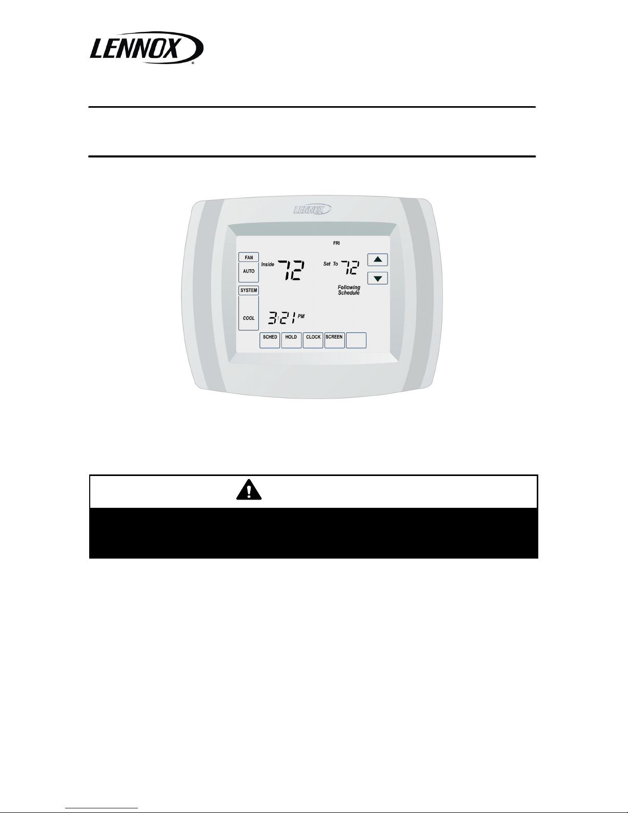
3 Heat / 2 Cool Programmable
Touch Screen Thermostat
INSTALLATION
INSTRUCTIONS
WARNING
This thermostat is to be installed by a qualified service technician or
other qualified agency in accordance with the manufacturer’s instructions, all codes, and requirements of the authority having jurisdiction.
505,044M
8/2007
Page 2

Page 2
Table of Contents
General Page 2. . . . . . . . . . . . . . . . .
Shipping and Packing List Page 2.
NecessaryTools Page 2. . . . . . . . . .
Thermostat Location Page 2. . . . . .
Remove Existing Thermostat Page 3
Thermostat Installation Page 4. . . .
Wiring Connections Page 4. . . . . . .
LED Indicator Page 5. . . . . . . . . . . .
Outdoor Temp. Sensor Page 5. . . .
Field Wiring Diagrams Page 6. . . .
Install Batteries Page 8. . . . . . . . . .
Attach T’stat to Wallplate Page 8. .
Set Calendar and Clock Page 8. . .
Adv. Heat Pump Features Page 9.
Installer Set−Up Page 11. . . . . . . . . .
System Test Page 19. . . . . . . . . . . . .
Troubleshooting Page 20. . . . . . . . . .
General
The Lennox X4147 programmable
touch-screen thermostat provides
control for up to three stages of heating
and two stages of cooling. The thermostat may be used to control either a
conventional HVAC system which includes an outdoor condensing unit and
indoor furnace or a heat pump unit and
indoor air handler. The thermostat terminal block accommodates 24V power
common from the furnace or air handler. Three AAA alkaline batteries are
provided to be used as an alternate
power source or as a back−up in case
of an interruption of power.
Shipping and Packing List
Package 1 of 1 contains
1 − Assembled thermostat (includes
wallplate and thermostat)
1− Bag assembly containing the fol-
lowing:
2 − Screws
2 − Wall anchors
3 − AAA alkaline batteries
1 − Installation instruction
1 − Owner’s guide
1 − Warranty certificate
Necessary Tools
S No. 2 Phillips screwdriver
S Standard pocket screwdriver
S Drill
S Drill bits (use 3/16" for drywall and
7/32" for plaster)
S Pencil
S Level
S Hammer
S Electrical tape
Thermostat Location
Install the thermostat about 5 feet
(1.5m) above the floor in an area with
good air circulation.
Do not install the thermostat where it
may be affected by the following:
S Drafts or dead spots behind doors
and in corners.
S Hot or cold air from ducts.
S Radiant heat from the sun or ap-
pliances.
S Concealed pipes or chimneys.
S Adjacent unconditioned areas
(outside wall behind the thermostat).
Page 3
Page 3
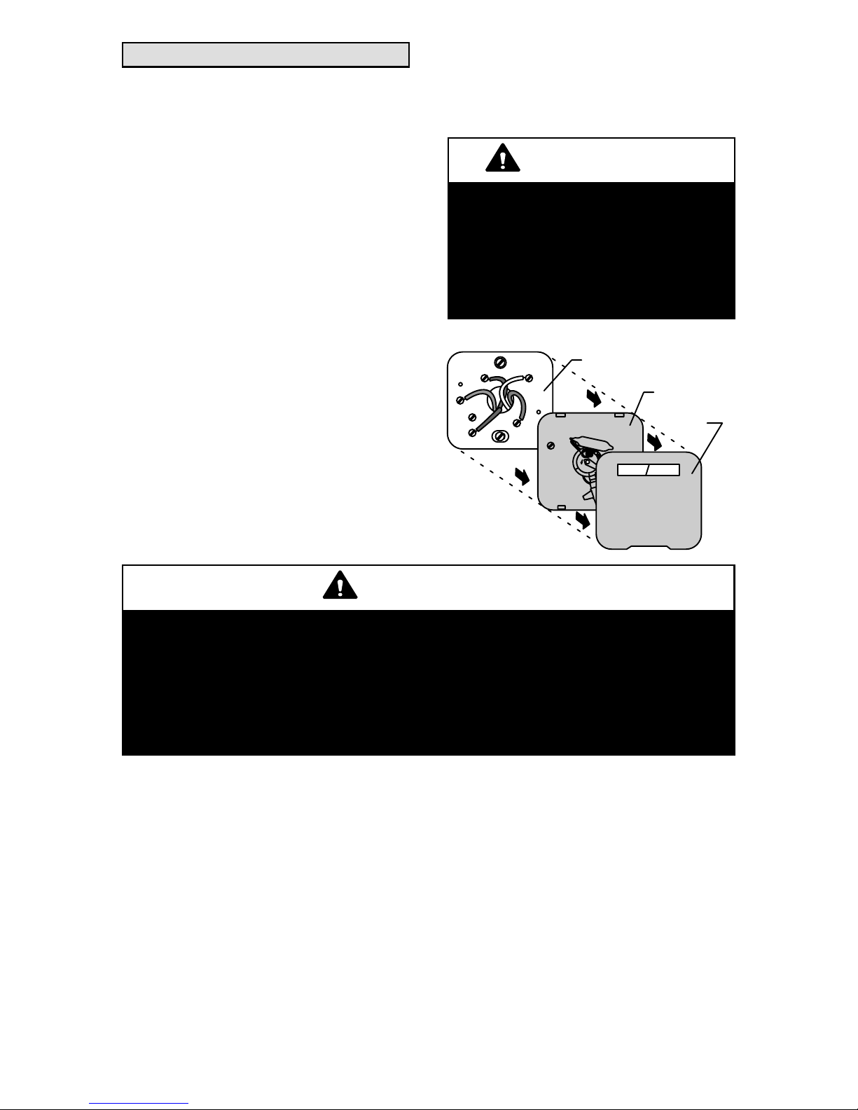
Remove Existing Thermostat
If this thermostat is being used to replace an existing thermostat, remove
the old thermostat:
1 − Turn off power at the heating and/
or cooling system or fuse/circuit
breaker panel.
2 − Remove the cover from the exist-
ing thermostat.
3 − Remove securing screws and re-
move existing thermostat from
wall or wallplate. Disconnect and
label the existing wires.
4 − Remove any remaining portion of
the existing thermostat from the
wall. Do not install the replacement thermostat faceplate on the
existing wallplate. Though the
wallplates may appear to be the
same and the faceplate may fit on
the existing wallplate, the terminal
positions may vary in important
ways. In addition, serial number
and part number information is
carried on the replacement wallplate.
Do not allow the thermostat wires
to fall behind the drywall.
WARNING
This thermostat must be
installed using the provided replacement wallplate.
Failure to do so will bypass thermostat control and activate continuous heating.
Y
G
C
R
W
OLD THERMOSTAT
.18
.
2
.
25
.
3
.
9
.
7
.
5
.
4
L
O
N
G
E
R
THERMOSTAT
COVER
WALLPLATE
WARNING
MERCURY NOTICE
If the existing thermostat includes a mercury bulb, the thermostat must
be disposed of properly.
Contact your local waste management authority for instructions regarding recycling and proper disposal of thermostats which include
mercury bulbs.
Page 4

Page 4
Thermostat Installation
The thermostat may be installed horizontally in a 4 in. X 2 in. (101.6 mm X
50.8 mm) wiring box or on the wall using the provided anchors.
1 − Separate the wallplate from the
thermostat as shown.
THERMOSTAT
WALLPLATE
WIRE HOLE
2 − Pass the labeled wires through the
hole on the wallplate.
3 − Position the wallplate on the wall
with the arrow pointing up. Level
the wallplate (for appearance
only) and use a pencil to mark the
mounting holes.
WALLPLATE
LEVEL
PLACE LEVEL ON
SUPPORT TABS
MARK
MOUNTING
HOLES (2)
4 − If anchors are used, move the
wallplate aside and drill two new
holes (3/16" for drywall; 7/32" for
plaster).
5 − Tap the provided wall anchors into
the drilled holes until the back of
the anchor head touches the wall
surface.
6 − Position the wallplate over the an-
chors and pull the thermostat
wires back through the wiring
opening.
7 − Secure the wallplate using the
provided screws.
DRILLED
HOLES (2)
WALL
ANCHORS (2)
MOUNTING
SCREWS (2)
WALLPLATE
NOTE
Thermostat heat function will
not operate if thermostat has
been stored at, or is being used
in, ambient temperatures at or
above 90°F. Heat function will be
enabled after thermostat has
been placed in ambient temperatures less than 90°F for about 30
minutes.
Wiring Connections
WARNING
Use minimum 18 guage wire for
all thermostat connections.
IMPORTANT
Do not connect the wires to this
thermostat based on wire color.
Improper wiring may cause
damage to the HVAC system.
Page 5
Page 5
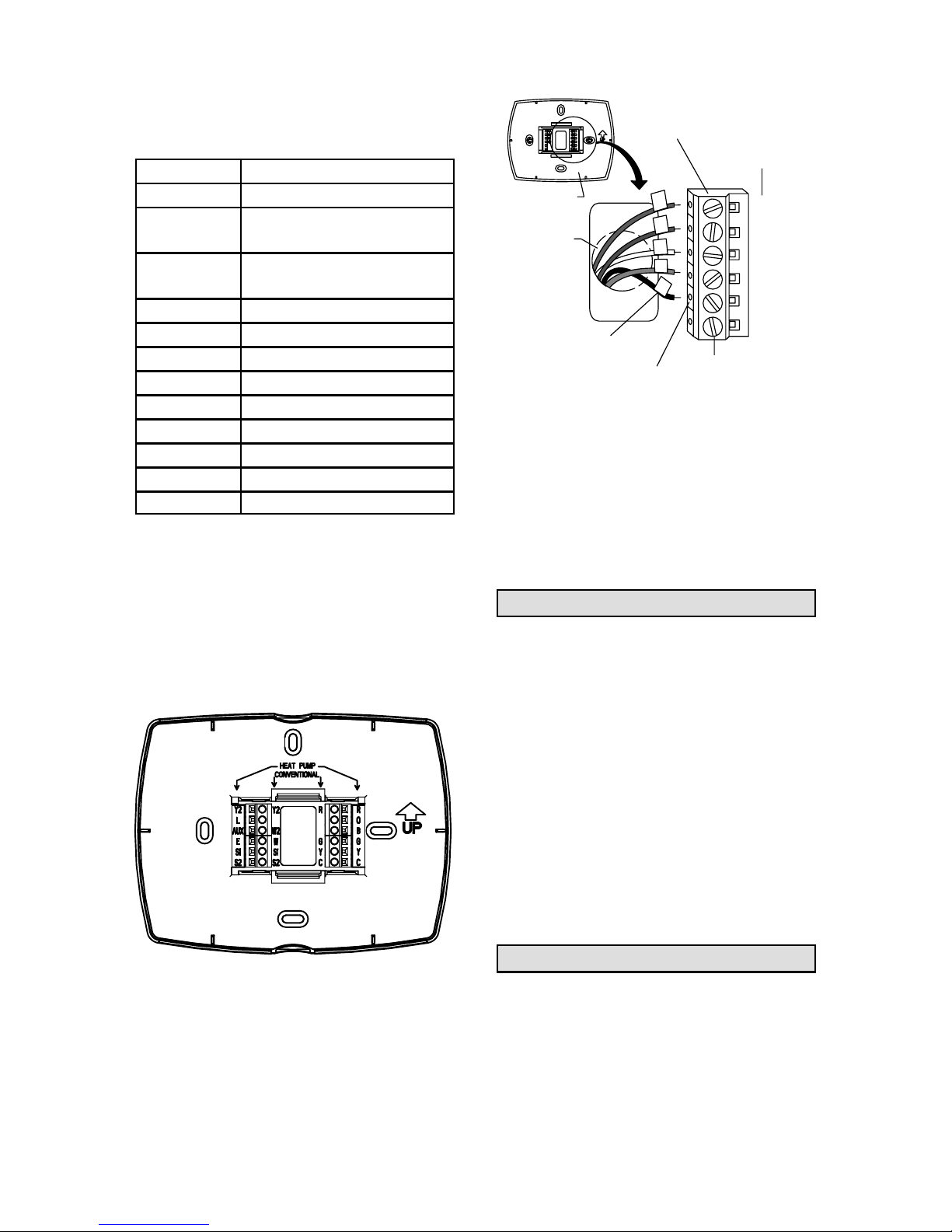
1 − Make wiring connections per the
appropriate wiring diagram on
page 6 or 7. Refer to the table
below for terminal designations.
Terminal Description
Y2 Second−stage cooling
W2 (AUX)
Second−stage heating
(or auxiliary heating)
W (E)
First−stage heating
(or emergency heating)
S1 Remote outdoor sensor
S2 Remote outdoor sensor
R 24V power
O Reversing valve
B Reversing valve
G Fan relay
Y First−stage cooling
C 24V common
L Equipment monitor
2 − Refer to inner terminal labels
when using the thermostat with
conventional systems (gas, oil or
electric heat plus air conditioning).
Refer to outer terminal labels in
heat pump applications. See figure below.
3 − Loosen screws of terminals that
will be used. Insert appropriate
wires in the terminal block under
the loosened screws. Securely
tighten each screw.
C
Y
B
O
R
G
INSERT WIRE IN HOLE
WIRE HOLE
WALLPLATE
SCREW
TERMINALS
LETTER
DESIGNATIONS
LABELED WIRES
TERMINAL
BLOCK
4 − Connect wires to the correspond-
ing screw terminals per the appropriate diagram.
5 − Push excess wire back into the
wall.
6 − Plug hole with nonflammable in-
sulation to prevent drafts from affecting thermostat.
LED Indicator
An LED indicator is located in the upper right corner of the thermostat. It is
only visible when lit.
When an equipment monitor is connected to the thermostat L terminal,
the LED lights when the monitor sends
a check or failure message to the thermostat.
The LED requires the use of 24Vac
common power. The indicator will not
light when the thermostat is powered
by the batteries alone, or when 24Vac
power is interrupted.
Outdoor Temperature Sensor
Install the optional outdoor temperature sensor (X4148) as outlined in the
instructions provided with the sensor.
Page 6

Page 6
Field Wiring Diagrams
TYPICAL CONVENTIONAL MULTI−STAGE APPLICATION
TWO−STAGE HEAT / TWO−STAGE COOL
TYPICAL MULTI−STAGE HEAT PUMP APPLICATION
NO AUXILIARY HEAT
TYPICAL MULTI−STAGE HEAT PUMP APPLICATION
WITH AUXILIARY HEAT
Page 7

Page 7
Field Wiring Diagrams (Continued)
TYPICAL SINGLE−STAGE HEAT PUMP SYSTEM WITH AUXILIARY HEAT
TYPICAL SINGLE−STAGE HEAT PUMP SYSTEM WITHOUT AUXILIARY HEAT
Page 8

Page 8
Install Batteries
1 − Install three provided AAA alkaline
batteries in the back of the thermostat as shown.
BACK OF THERMOSTAT
BATTERIES
(3)
+
+
+
2 − Remove tab from the lower right−
hand corner of the thermostat
back to activate the real−time
clock.
REMOVE DURING
INSTALLATION
REMOVE
TAB
REMOVE DURING
INSTALLATION
Attach Thermostat to Wallplate
NOTE − The thermostat may be programmed before it is secured to the
wallplate.
1 − Align the terminal blocks on the
wallplate with the pins on the back
of thermostat.
2 − Push the thermostat straight onto
the pins until it snaps into place.
3 − Turn on power at the furnace or air
handler or at the fuse or circuit
breaker.
PINS ON
BACK OF
THERMOSTAT
WALLPLATE
TERMINAL
SCREW
BLOCK
Set Calendar and Clock
This thermostat is designed to automatically keep the current time and
date in memory for up to ten years, under normal use, once the calendar has
been set. When power is first applied to
the thermostat, the display is ready to
set the calendar.
1 − Use the arrow keys to set the year,
month and day.
2 − Press the DONE key.
DONE
USE
ARROWS
TO SET
YEAR
SET
CURRENT
DATE
SET
MONTH
MON WED THU FRI SATTUE
3 − Use the arrow keys to set the cur-
rent time.
4 − Press the DONE key.
DONE
MON WED THU FRI SAT
AM
PM
USE
ARROWS
TO SET
TIME
TUE
NOTE − Date and time may be adjusted after the initial set−up using either the installer or user set−up menu.
Page 9

Page 9
Advanced Heat Pump Features
The thermostat installer set−up may be
configured in several different ways to
ensure the desired system operation.
Heat Pump Application
Dual Fuel (Fossil Fuel) Aux. Heat
Outdoor Temperature Sensor and
Thermostat Control Aux. Heat
(No external dual fuel kit)
Installer set−up as follows:
S Installer set−up number 0170 −−
option 7, 11, or 12 −− heat pump.
S Installer set−up number 0200 −−
option 1 −− back−up heat is fossil
fuel.
S Installer set−up number 0210 −−
option 0 −− no external fossil fuel
kit.
S Installer set−up number 0340 −− not
shown −− outdoor temperature
sensor for control option chosen
by default.
S Installer set−up number 0350 −−
choose appropriate balance point
temperature.
Heating Mode Operation
Outdoor Temp. above Balance
Point
When the outdoor temperature is
above the selected balance point, the
compressor satisfies the heating demand. However, if the room thermostat
senses an indoor temperatature drop
of 2°F or more while the compressor is
operating, the heat pump operation will
stop and the furnace will satisfy the remaining heating demand.
NOTE − The balance point setting is
selected using Installer Set−Up Number 0350.
Heating Mode Operation
Outdoor Temp. below Balance Point
When the outdoor temperature is below the selected balance point, only
the furnace (fossil fuel) operates to satisfy the heating demand. The fan (G
terminal) does not energize when the
thermostat calls for heat.
Emergency Heat Operation
When the emergency heat mode of operation is selected by the thermostat,
compressor operation is locked out.
The first stage of heat becomes what is
connected to the thermostat E terminal. The second stage of heat becomes what is connected to the Aux.
terminal. In cases where there is only
one source of non−compressor heat,
the E terminal must be jumped to the
Aux. terminal.
Heat Pump Application
Dual Fuel (Fossil Fuel) Aux. Heat
Using External Dual Fuel Kit
Installer set−up as follows:
S Installer set−up number 0170 −−
option 7, 11, or 12 −− heat pump.
S Installer set−up number 0200 −−
option 1 −− back−up heat is fossil
fuel.
S Installer set−up number 0210 −−
option 1 −− external fossil fuel kit is
controlling heat pump auxiliary
heat.
S Installer set−up number 0340 −−
option 0 or 1 −− outdoor temperature sensor not used or used for
display only.
S Installer set−up number 0350 −−
choose appropriate balance point
temperature.
Heat pump operation is determined by
external fossil fuel kit.
Page 10

Page 10
Heat Pump Application
Electric Auxiliary Heat
with Outdoor Temperature Sensor
S Installer set−up number 0170 −−
heat pump.
S Installer set−up number 0200 −−
back−up heat is electric.
S Installer set−up number 0340 −−
outdoor temperature sensor for
control option chosen.
S Installer set−up number 0350 −−
choose appropriate compressor
lock−out temperature.
S Installer set−up number 0360 −−
choose appropriate auxiliary lock−
out temperature.
NOTE − There is a minimum 5°F deadband between the compressor and
auxiliary heat lock−out temperatures.
Heating Mode Operation
When the outdoor temperature is below the compressor lock−out temperature (balance point), only the auxiliary
heat operates.
When the outdoor temperature is
above the auxiliary lock−out temperature (balance point), only the compressor operates.
When the outdoor temperature is between the two temperatures, both the
compressor and auxiliary heat operate.
COMPRESSOR
LOCK−OUT
TEMPERATURE
AUXILIARY
LOCK−OUT
TEMPERATURE
COMPRESSOR ONLY
BOTH COMPRESSOR AND
AUXILIARY HEAT
AUXILIARY ONLY
50
35
OUTDOOR TEMPERATURE
Emergency Heat Operation
When the thermostat is set for the
emergency heat mode, the compressor and auxiliary lock−out features are
turned off. Compressor operation is
locked out. The first stage of heat becomes what is connected to the thermostat E terminal. The second stage of
heat becomes what is connected to the
Aux. terminal.
Page 11

Page 11
Installer Set−Up
Use the following steps and the Installer Set−Up menu to match the thermostat to the HVAC system.
1 − Press and release the SYSTEM
key.
2 − Press and hold the two blank keys
on either side of the center blank
key for approximately five seconds.
MON
CANCEL
UET WED THU FRI SATAAT SUN
PM
SS M
EMHT
Y TE
COOL
FOLLOWING
SCHEDULE
SET TO
OFF
DONE
3 − Release the two keys when the
thermostat display matches the
display below.
DONE
4 − Refer to the following figure to see
how the thermostat keys are used
to make selections from the set−up
menu.
DONE
INSTALLER
SET−UP
NUMBER
CURRENT
SETTING
ADVANCE TO NEXT
INSTALLER SET−UP
EXIT
INSTALLER
SET−UP
CHANGE THE
CURRENT
SETTING
5 − The installer set−up number is dis-
played on the left−hand side of the
screen. The current installer set−
up number is displayed on the
right−hand side of the screen. Use
the up and down arrows on the
right−hand side of the thermostat
to select the proper setting for that
particular set−up number.
6 − After the proper selection has
been made, use the up arrow in
the center of the thermostat to advance to the next set−up screen.
7 − Refer to the tables on pages 9
through 15 to make proper set−up
choices for your application.
8 − When all set−up selections have
been made, press the DONE key
to save your settings. Thermostat
display will return to the main
screen.
NOTE − Press and release the SYSTEM key, then press and hold the center blank key to access the user set−up
screens. The user set−up options are
limited to those features that would be
used by the homeowner. Press the
DONE key when finished.
Page 12

Page 12
InstallerSet−
Up No.
Installer
Set−Up
Name
Selection Description
(Factory setting in bold print)
Notes
0120
Date
(Year/
first)
Select first two digits of current calendar
year (20 for 2007, etc.)
Factory setting = 20.
0130
Date
(Year/
last)
Select last two digits of current calendar
year (07 for 2007, etc.); 01 to 99 available.
0140
Date
(Month)
Select number that represents current calendar month.
Factory setting = 8.
0150
Date
(Day)
Select number that represents current calendar date.
Factory setting = 19.
0160
Schedule
Options
0 − Non−programmable.
4 − 7−day programming. Factory setting.
0170
System
Type
1 − Single−Stage Heating and Cooling
(Conventional) −− Gas, oil or electric
heating with central air conditioning.
Factory setting.
2 − Single−Stage Heat Pump with No Back−
Up or Auxiliary Heat.
3 − Heat Only without Fan (Conventional).
4 − Heat Only with Fan (Conventional).
5 − Hot Water Heat Only (Conventional) −−
Gas or oil hot water heat. Power open/
power close hot water zone valves or normally open valves.
6 − Cooling Only (Conventional) −− Central
air conditioning only.
7 − Two Heat / One Cool Heat Pump −−
Heat pump with auxiliary or back−up heat.
8 − Two Heat / Two Cool Multi−Stage (Conventional).
9 − Two Heat / One Cool Multi−Stage (Conventional).
10 − One Heat / Two Cool Multi−Stage
(Conventional).
11 − Two Heat / Two Cool Heat Pump −− No
auxiliary heat.
12 − Three Heat / Two cool Heat Pump −−
With auxiliary heat.
Available options and defaults vary by
system type.
System type
selection automatically modifies certain default settings
and installer
set−up options.
table continued on next page
Page 13

Page 13
InstallerSet−
Up No.
Notes
Selection Description
(Factory setting in bold print)
Installer
Set−Up
Name
0180
Fan
Control
Heating
0 − Gas or Oil Heat −− Heating system
controls fan during heating demand.
Factory setting.
1 − Electric Heat −− Thermostat controls fan
during heating demand.
Available only if
conventional
system chosen.
Setting defaults
to electric heat
if heat pump is
chosen.
0200
Auxiliary
Heat
Source
0 − Electric heat is used as auxiliary
heat source in heat pump application.
Factory setting.
1 − Fossil fuel is used as auxiliary heat
source in heat pump application.
Available only if
2 ht / 1 cool or
3 ht / 2 cool
heat pump system is chosen.
0210
External
Fossil
Fuel Kit
0 − No external fossil fuel kit is controlling
heat pump auxiliary heat. Thermostat used
to control dual fuel. Must install outdoor
temperature sensor and installer set−up
number 0340 must be set to selection 2.
1 − External fossil fuel kit is controlling
heat pump auxiliary heat. Factory setting.
Shown only in
heat pump applications when
fossil fuel is
chosen as
back−up heat
source.
0220
Cycles
per Hour
(cph) 1st
Stage
Compressor
3 − Recommended setting for compressors. Factory setting.
Settings of 1 − 6 cph available.
0230
Cycles
per Hour
(cph) 2nd
Stage
Compressor
3 − Recommended setting for compressors. Factory setting.
Settings of 1 − 6 cph available.
Shown only
when two−stage
cooling is selected.
0240
Cycles
per Hour
(cph) 1st
Stage
Conventional
Heating
1 − Recommended for use with steam and
gravity.
3 − Recommended for use with hot water
heat and high−efficiency (90% or higher)
furnaces.
5 − Recommended for use with standard−efficiency (less than 90%) fossil
fuel furnaces.
9 − Recommended for use with electric furnaces.
Settings of 1 − 12 cph available.
Shown only
when conventional system is
selected.
table continued on next page
Page 14

Page 14
InstallerSet−
Up No.
Notes
Selection Description
(Factory setting in bold print)
Installer
Set−Up
Name
250
Cycles
per Hour
(cph) 2nd
Stage
Conventional
Heating
(or Auxiliary Heat
for 2
Heat / 1
Cool
Heat
Pump
Applications)
1 − Recommended for use with steam and
gravity.
3 − Recommended for use with hot water
heat and high−efficiency (90% or higher)
furnaces.
5 − Recommended for use with standard−efficiency (less than 90%) fossil
fuel furnaces. Factory setting.
9 − Recommended for use with electric furnaces or electric auxiliary heat.
Settings of 1 − 12 cph available.
Shown only
when two−stage
heating is selected.
0260
Cycles
per Hour
(cph) 3rd
Stage
Heating
1 − Recommended for use with steam and
gravity.
3 − Recommended for use with hot water
heat and high−efficiency (90% or higher)
furnaces.
5 − Recommended for use with standard−
efficiency (less than 90%) fossil fuel furnaces.
9 − Recommended for use with electric
furnaces or electric auxiliary heat. Factory setting.
Settings of 1 − 12 cph available.
Shown only in 3
heat / 2 cool
heat pump applications.
0270
Cycles
per Hour
(cph)
Emer−
gency
Heating
3 − Recommended for use with hot water
heat and high−efficiency (90% or higher)
furnaces.
5 − Recommended for use with standard−
efficiency (less than 90%) fossil fuel furnaces.
9 − Recommended for use with electric
strip heat in heat pump applications.
Factory setting.
Shown only in 2
heat/1 cool or 3
heat/2 cool heat
pump applications.
0280
Continuous
Backlight
0 − Backlight not lit continuously. Backlight comes on when key is pressed.
Factory setting.
1 − Backlight is continuously lit. (Thermostat must be powered by 24V common
wire for this feature to be allowed.)
Option always
shown; however, t’stat must
be powered by
24V common.
table continued on next page
Page 15

Page 15
InstallerSet−
Up No.
Notes
Selection Description
(Factory setting in bold print)
Installer
Set−Up
Name
0300
Changeover
0 − Manual changeover from heating
mode to cooling mode. Factory setting.
1 − Auto−changeover from heating mode to
cooling mode.
0310
Deadband
(Minimum differential
between
heating
and cooling setpoints)
2 − 2°F (1.5°C)
3 − 3°F (2°C). Factory setting.
4 − 4°F (2.5°C)
5 − 5°F (3°C)
6 − 6°F (3.5°C)
7 − 7°F (4°C)
8 − 8°F (4.5°C)
9 − 9°F (5°C)
Option shown
only when auto−
changeover has
been selected.
0320
Temperature Display
Scale
0 − Fahrenheit (factory setting).
1 − Celsius
0330
Daylight
Savings
0 − Daylight savings disabled.
1 − Daylight savings enabled using
pre−2007 calendar. Factory setting.
2 − Daylight savings enabled using 2007
DST calendar (all US; some Canada).
Set to 0 in
areas that do
not follow daylight savings.
0340
Remote
Outdoor
Temperature Sensor
0 − No remote outdoor temperature
sensor. Factory setting.
1 − Outdoor temperature sensor used for
display only.
2 − Outdoor temperature sensor used to
control heat pump lock−out settings.
Defaults and
options depend
on system type
selection.
When setting
0210 is set to 0,
setting defaults
to 2 and item is
not shown.
0350
Heat
Pump
Compressor
Lock−Out
(Balance
point)
0 − No compressor lock−out. Factory
setting.
15°F (−9.5°C).
20°F (−6.5°C).
25°F (−4°C).
30°F (−1°C).
35°F (1.5°C).
40°F (4.5°C).
45°F (7°C).
Shown only if
outdoor temperature for control
is selected. Default depends
on other selections.
table continued on next page
Page 16

Page 16
InstallerSet−
Up No.
Notes
Selection Description
(Factory setting in bold print)
Installer
Set−Up
Name
0360
Heat
Pump
Auxiliary
Heat
Lock−Out
0 − No auxiliary heat lock−out. Factory
setting.
40°F (4.5°C).
45°F (7°C)
50°F (10°C).
55°F (13°C).
60°F (15.5°C).
Shown only if
electric is selected for back−
up heat source
and outdoor
temp. sensor
for control is selected.
0500
Filter
Change
Reminder
0 − Filter change reminder off. Factory
setting.
1 − 10 run time days.
2 − 30 run time days.
3 − 60 run time days.
4 − 90 run time days.
5 − 120 run time days.
6 − 365 run time days.
Run time based
on call for fan.
0510
Humidifier Pad
Replacement
Reminder
0 − Humidifier pad replacement reminder off. Factory setting.
1 − 90 run time days.
2 − 180 run time days.
3 − 365 run time days.
0520
UV Lamp
Replacement Reminder
0 − UV lamp replacement reminder off.
Factory setting.
1 − 365 run time days.
0530
Adaptive
Intelligent
Recovery
0 − Conventional Recovery −− System
starts recovery at programmed time.
1 − Adaptive Intelligent Recovery −− System starts recovery early so that setpoint is reached by the start of the program period. Factory setting.
0540
Number
of Periods
2 − Two periods (wake and sleep) available.
4 − Four periods (wake, leave, return,
sleep) available. Factory setting.
Shown only
when programmable is chosen.
Setting applies
to all days of
the week.
0580
Minimum
Compressor−
Off Time
Settings of 0 − 5 available.
5 − Five−minute compressor−off time
setting. Factory setting.
table continued on next page
Page 17

Page 17
InstallerSet−
Up No.
Notes
Selection Description
(Factory setting in bold print)
Installer
Set−Up
Name
0600
Heat
Temperature
Range
(°F)
Settings of 40 − 90 available in 1°F increme.
Factory setting = 90.nts.
Shown in 1/2°C
increments
0610
Cool
Temperature
Range
(°F)
Settings of 50 − 99 available in 1°F increments.
Factory setting = 50.
Shown in 1/2°C
increments
0640
Clock
Format
12 − 12−hour clock. Factory setting.
24 − 24−hour clock.
0650
Heating
Mode
Extended
Fan On
Time
0 − No extended fan operation after
heating demand satisfied. Factory setting.
90 − Fan operation continues for 90 seconds after heating demand satisfied.
Not shown
when fan operation is set to
fossil fuel or in
cool only systems.
0660
Cooling
Mode
Entended
Fan On
Time
0 − No extended fan operation after
cooling demand satisfied. Factory setting.
90 − Fan operation continues for 90 seconds after cooling demand satisfied.
Not shown in
heat only systems.
0670
Keypad
Lock−Out
0 − Keypad unlocked −− all functions are
available. Factory setting.
1 − Keypad partially locked −− only temp. up
and down keys and ability to enter installer
set−up mode and modify set−up selections
are enabled.
2 − Keypad fully locked −− only ability to enter installer set−up mode and modify set−up
selections are enabled.
0680
Heating
Mode
Temperature Control
1 − Less aggressive control. Select this
setting if temperature is overshooting the
setpoint. Heating may turn off before the
setpoint is reached.
2 − Standard control. Factory setting.
3 − More aggressive control. Select this
setting if temperature is undershooting the
setpoint. Heating may remain on after the
setpoint is reached.
Applies to recovery ramp
and use of auxiliary heat during recovery.
table continued on next page
Page 18

Page 18
InstallerSet−
Up No.
Notes
Selection Description
(Factory setting in bold print)
Installer
Set−Up
Name
0690
Cooling
Mode
Temperature Control
1 − Less aggressive control. (Cooling may
turn off before setpoint reached).
2 − Standard control. Factory setting.
3 − More aggressive control. (Cooling may
remain on after setpoint reached).
Applies to recovery ramp.
0700
Temperature Display Offset
−3°F (−1.5°C).
−2°F (−1°C).
−1°F (−.5°C).
0 − No difference in displayed temperature and actual room temperature. Factory setting.
1°F (.5°C).
2°F (1.5°C).
3°F (2°C).
0710
Reset
Thermostat
0 − No thermostat reset. Factory setting.
1 − Resets all installer set−up options to
default values and resets schedule to
default setting.
Only calendar
settings and
time are retained.
Page 19

Page 19
System Test
The system test function allows the installer to check the HVAC system after
the thermostat set−up has been completed. The system test function is accessed through the installer set−up
menu.
1 − Press and release the SYSTEM
key.
2 − Press and hold the two blank keys
on either side of the center blank
key for approximately five seconds, until the screen changes.
3 − Use the down arrow in the center
of the thermostat to reach the installer test selections.
4 − The installer test number is dis-
played on the upper portion of the
screen. Press the up or down arrow next to the word test on the
screen to change the output to be
tested.
5 − Refer to the following table to se-
lect proper test options.
CAUTION
While the system is in the test
mode, the compressor minimum−off time is bypassed.
Installer Test No. Installer Set−Up Name Selection Description
Test 1 Installer Test Cool
0 − Cooling is off (factory setting).
1 − First−stage cooling is activated.
2 − Second−stage cooling is activated.
Test 2 Installer Test Fan
0 − Fan is off (factory setting).
1 − Fan is activated.
0 − Heating is off (factory setting).
1 − First−stage heat is activated.
Test 3
Install
er Test Hea
t
2 − Second−stage heat is activated.
−
−
-
3
−
Third−stage (auxiliary) heat is ac
-
tivated.
Installer Test Emergen-
0 − Emergency heat is off (factory
Test 4
Installer Test Emergen
cy Heat
setting)
.
1 − Emergency heat is activated.
Page 20

Page 20
Troubleshooting
Symptom Possible Cause Action
Display does not come
on.
Thermostat is not being
powered.
1− Check to see that there
is 24V between R and C
terminals.
2− Check to see that batteries are properly
installed.
Temperature settings do
Upper or lower temperature limits were reached.
1− Check temperature setpoints.
2− Check installer set−up
numbers 0600 and 0610.
Modify, if necessary.
not change
.
Keypad is fully locked.
Check installer set−up
number 0670 and change
keypad lock option, if necessary.
Thermostat minimum−off
time is activated.
Wait up to 5 minutes for
the system to respond.
Heating or cooling does
System selection has not
been set to heat or cool.
Select proper system
mode.
not come on.
System type selection is
incorrect.
Check installer set−up
number 0170 and make
sure proper system type
is selected.
Thermostat is calling for
heat (Heat ON) or cool
(Cool ON); but HVAC system is not operating.
Heating or cooling equipment is not operating.
1− Check wiring.
2− Check installer set−up
number 0170 and make
sure proper system type
is selected.
3− Verify operation of
equipment in system test
mode.
Thermostat does not
respond when touch
screen is pressed.
Keypad is fully locked.
Check installer set−up
number 0670 and change
keypad lock option, if necessary.
NOTE − Perform installer system tests (page 19) to verify thermostat
control of HVAC system.
 Loading...