

Page 1
1
©2017 Lennox Industries Inc.
Dallas, Texas, USA
INSTALLATION/
OPERATION
INSTRUCTIONS
CONTROLS
507561-03
5/2017
Supersedes 8/2015
This manual must be left with the
owner for future reference.
WARNING
!
Improper installation, adjustment,
alteration, service or maintenance
can cause property damage,
personal injury or loss of life.
Installation and service must
be performed by a licensed
professional HVAC installer (or
equivalent) or service agency.
Frequent changes to operating
mode may cause system
malfunction. Allow at least one
minute between mode changes to
allow the system to stabilize.
IMPORTANT!
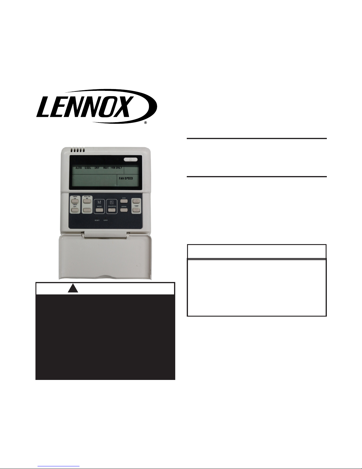
Lennox Mini-Split
Systems Wired Indoor
Unit Controller
Page 2
2
Shipping and Packing List
Package 1 of 1 contains;
1 – Wired Controller
1 – Installation and operation manual
1 – Cable with connector – 20 ft. (6 m)
General
The M0STAT61Q-1 mini-split wired controller is a wired local controller for Lennox
mini-split indoor units.
Requirements
Turn off power supply before beginning installation. Use this controller only as described in this manual. Do not install the controller on outside walls (where there is
unconditioned space on opposite side of wall) or in locations where direct sunlight
may be present.
Installation
CAUTION
!
Clean controller using a clean,
damp cloth. Do not spray cleanser
on or around controller.
CAUTION
!
Do not install controller in areas
where heavy oil, vapor, or gases
containing sulfur may exist or the
controller may be damaged.
Do not operate controller with wet
hands.
WARNING
!
Be sure that power supply has
been turned off before beginning
installation.
WARNING
!
Page 3
3
IMPORTANT!
Read all of the information in this
manual before using this controller.
All wiring must conform to local and
national building and electrical codes
and ordinances. This is a 5 VDC
controller. Do not install on voltages
higher than 5 VDC.
IMPORTANT!
The provided cables must be used.
Do not use excessive force while
pulling the cable or when making the
connections.
• This manual provides the installation
instructions for this controller. Refer
to the included wiring diagram to connect the controller to the indoor unit.
• The controller uses low voltage. Keep
a minimum distance of 12” (305 mm)
between low voltage control wire and
high voltage power wires.
• Ground the shielded control wiring.
• Do not use a megger to test insulation.
• The controller cable length should not
exceed 40 ft. (12 m).
Page 4
4
2. Remove the cover from the wall plate using a at-head screwdriver. See gure 2.
3. Mount the wall plate as appropriate for your application. See gure 3.
NOTE – Provide for future maintenance by allowing enough slack in the wiring to
allow the controller to be removed from the wall if needed.
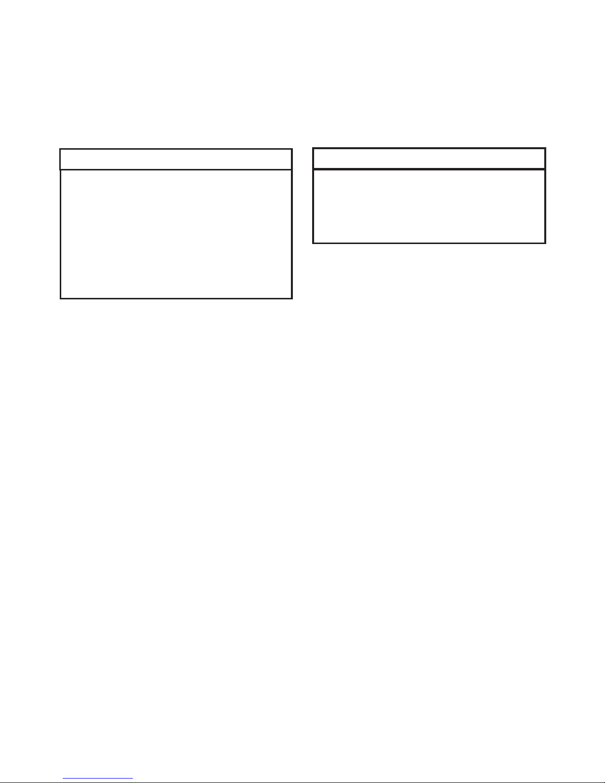
Figure 2. Remove cover from wall plate.
Slots
Figure 1. Wiring Connections
Indoor unit
display board
5-conductor wire
5-conductor wire
1. Connect controller to indoor unit main control board by inserting the plug of the
5-conductor cable into the socket provided at the indoor unit
Page 5

5
Figure 3. Mount wall plate
4. Attach the wall plate using the provided screws. See gure 3.
J-box
Back plate
Back plate
Screws
Screw
Screws
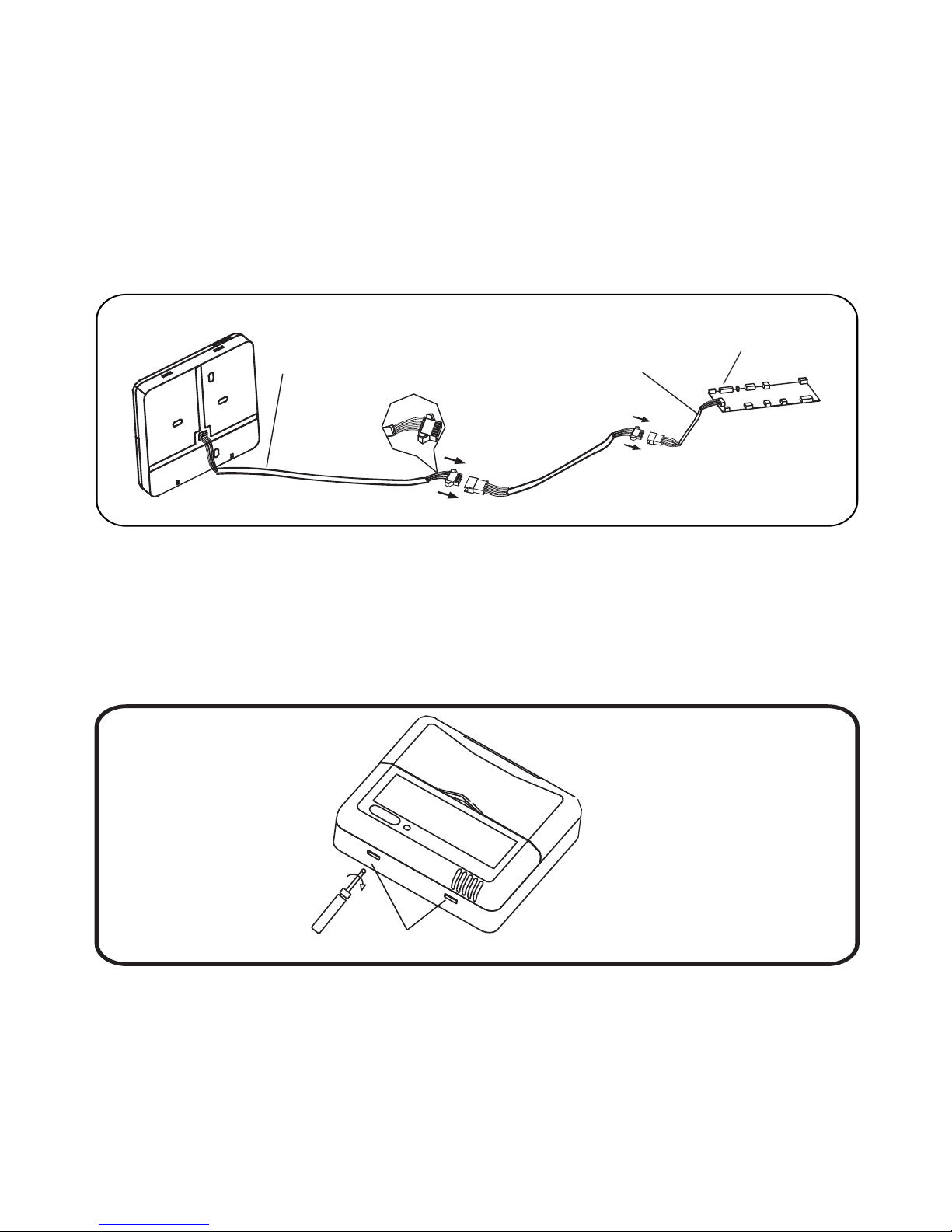
Figure 4. Reattach cover to wall plate
5. Reattach the cover to the wallplate. See gure 4.
Page 6

6
RUN
GND
+5V
Field Wiring Diagram
Figure 5. Typical wiring diagram between wired controller and indoor unit
Indoor unit
display board
Shielded
5-conductor cable
Wired
controller
Specications
Table 1. Specications
Input voltage 5 VDC
Ambient temperature 23~110°F (-5~43°C)
Ambient humidity RH40%~RH90%
Emitter tube
5-way terminal
Page 7

7
Display
1
2
1 12
Operation mode indication
Follow me function
ON/OFF indication
Timer ON/OFF
Temperature display zone
Lock
Fan speed indication
• Operation mode. These icons
show the current mode of operation. Press the mode button to scroll
through the operation modes:
Auto → Cool → Dry → Heat → Fan.
• Timer ON/OFF. These icons light
to indicate that the indoor unit has a
timed auto-start or auto-stop set .
• Follow me. This icon displays when
the air temperature sensor in the
wired remote controller is the sensor
being used by the indoor unit. When
this function is off, the indoor unit uses
a built-in sensor.
• ON/OFF. This icon displays when the
indoor unit is turned on.
• Fan speed. Displays the current fan
speed.
• Lock. This icon displays when the
controller is locked.
• Temperature display. Displays setpoint temperature.
Page 8

8
Description of Buttons
MODE BUTTON
TIMER ON BUTTON
FOLLOW ME BUTTON
TIMER OFF BUTTON
RESET BUTTON
ON / OFF BUTTON
ADJUST BUTTON ▲
ADJUST BUTTON ▼
SWING BUTTON
ECONOMY BUTTON
FAN SPEED BUTTON
LOCK BUTTON
TIMER
ON
TIMER
OFF
FOLLOW
ME
MODE
RESET
LOCK
FANSPEED
ECO
SWING
TEMP
Page 9

9
• Mode button. Press to scroll
through the operation modes:
Auto → Cool → Dry → Heat → Fan.
• Timer ON button. Press to set the
number of hours of delay before the
indoor unit begins operation.
• Timer OFF button. Press to set the
number of hours of delay before the
indoor unit stops operation.
• Follow Me button. Press to activate
the controller’s air temperature sensor. This transfers the temperature
sensing function from the indoor unit
to the controller. The indoor unit’s air
temperature sensor will be disabled.
• Reset button. Using a blunt-tipped
device (paper clip), press to cancel
current settings and reset remote controller to factory settings.
• On/Off button. Press to turn the indoor unit on or off.
• Up arrow button. Press to increase
the temperature setpoint or to scroll
through settings options.
• Down arrow button. Press to decrease the temperature setpoint or
scroll through settings options.
• Swing button. Press once to initiate
louver left & right oscillation. Press
again to stop louver oscillation. Louvers remain in place where stopped.
Not available in all indoor unit models.
• Economy button. Not used.
• Fan speed. Press to scroll through
the fan speeds: Auto → Low → Med
→ High
• Lock button. Using a blunt-tipped
device (paper clip), press to lock or
unlock the current setting.
Page 10

10
Operation
Start/stop operation
Press the LED power button.
• Controller ON: Power button LED lit
brightly.
• Controller OFF: Power button LED
not lit.
Select Fahrenheit or Celsius Display
Press and Up and Down buttons at the
same time, and hold for three seconds to
toggle between Fahrenheit and Celsius.
To set the operation mode
Press the Mode button to scroll through
the mode selections.
• Auto – System operates in cooling or
heating mode as determined by the
setpoint and the room temperature.
NOTE: The use of Auto mode for
multi-zone units is not recommend. All zones should be in the
same mode of operation to ensure
there is not a conict error mode.
• Cool – System operates in cooling
mode.
• Dry – System removes humidity according to preset conditions (fan
speed and setpoint temperature, not
a humidistat sensor). Cannot adjust
fan speed.
• Heat – System operates in heating
mode.
• Fan – Fan only, no heating or cooling.
To set (or change) the room temperature setting (setpoint)
Press the up arrow & down arrow buttons to adjust the setpoint.
Dry mode
1. Press the Power button, an LED light
on the indoor unit displays.
2. Press the Mode button to select Dry.
3. Adjust the temperature setpoint using
up and down arrow buttons.
NOTE – Fan speed is not adjustable.
Timer operation
Timer ON and Timer OFF are used to
turn on and turn off the indoor unit at selected intervals.
Timer ON operation
1. Press the Timer ON button. The Timer
on icon, the last auto-on time, and “h”
will display.
2. Press the Timer ON button again
to set the amount of time before the
indoor unit begins operation. Each
Page 11

11
press will increase the time in half
hour increments until 10 hours, then
the increment becomes 1 hour.
Timer OFF operation
1. Press the Timer OFF button. The Timer off icon, the last auto-off time, and
“h” will display.
2. Press the Timer OFF button again to
set the amount of time before the indoor unit stops operation. Each press
will increase the time in half hour increments until 10 hours, then the increment becomes 1 hour.
Modify Timer ON/OFF settings
1. Press either the Timer ON button or
the Timer OFF button to modify that
setting.
2. Continue to press the Timer ON or
Timer OFF button until the display
shows the new time. Each press will
increase the time in half hour increments until 10 hours, then the increment becomes 1 hour.
3. Set the timer to 0.0 to turn off timed
operation.
Page 12

12
Troubleshooting
Fault Codes (indoor unit)
E0 Indoor unit EEPROM error
E1 Communication error between indoor unit and outdoor unit
E3 Indoor fan speed error
E4 Indoor return air temperature sensor error
E5 Indoor coil temperature sensor error
EC Low refrigerant
EE High water level alarm
F0 Outdoor current overload sensed
F1 Outdoor ambient temperature sensor error
F2 Outdoor coil temperature sensor error
F3 Compressor discharge temperature sensor error
F4 Outdoor unit EEPROM error
F5 Outdoor unit fan speed error
P0 Inverter module IPM error
P1 High or low voltage protection
P3 Outdoor unit low temperature lockout
P4 Compressor drive error
-- Mode conict
P6 Compressor high-pressure or low-pressure switch open
 Loading...