

Page 1
INSTALLATION AND OPERATION
MANUAL
FREE-STANDING
AND INSERT
PELLET-FIRED STOVES
Free-Standing Model
Profi le® 20 FS-2
Free-Standing Model
Profi le 30 FS-2
Insert Model
Profi le 30 INS-2
RETAIN THESE
INSTRUCTIONS
FOR FUTURE
REFERENCE
These appliances must be properly installed and operated in order to prevent the possibility of a house fi re. Please read this entire installation and operation manual before
installing and using your pellet stove. Failure to follow these instructions could result
in property damage, bodily injury or even death. Contact your local building or fi re offi cials to obtain a permit and information on any installation requirements and inspection
requirements in your area.
P/N 775,023M, Rev. E, 09/2006
Page 2
IMPORTANT SAFETY AND
WARNIING INFORMATION
READ THIS MANUAL IN ITS
ENTIRETY AND UNDERSTAND
THESE RULES TO FOLLOW FOR
SAFETY.
CAUTION
Read this manual thoroughly
before starting installation. For
your safety, follow the installation, operation and maintenance
instructions exactly without
deviation. Failure to follow these
instructions may result in a possible fi re hazard and will void
the warranty. If this appliance is
not properly installed, a house
fi re may result. Contact local
building or fi re offi cials about
requirements and installation
inspection in your area.
WARNING
Improper installation, adjustment, alteration, service or
maintenance can cause injury
or property damage. Refer to
this manual. For assistance or
additional information consult
a qualifi ed installer, service
HEADER
HEADER
Sub Header
Sub Header
text
text
Oblique
Oblique
Figure
Figure
agency or the gas supplier.
WARNING
Do not attempt to alter or modify
the construction of the appliance or its components. Any
modifi cation or alteration may
void the warranty, certifi cation
and listings of this unit.
1. DO NOT CONNECT THIS UNIT TO
A CHIMNEY FLUE CONNECTED TO
ANOTHER APPLIANCE.
2. Do not connect this appliance to air
ducts or any air distribution system.
3. Do not install a fl ue damper in the
exhaust venting system of this appliance.
4. Do not use class B venting intended for
gas appliances as a chimney or connector pipe on a pellet-fi red appliance.
2
5. The minimum clearances must
be maintained for all combustible
surfaces and materials including;
furniture, carpet, drapes, clothing,
wood, papers, etc. Do not store fi rewood within this clearance space (see
Clearances on Pages 6 and 7).
6. INSTALLATION DISCLAIMER - This
stove’s exhaust system works with negative combustion chamber pressure and
a slightly positive chimney pressure.
Therefore, it is imperative that the
exhaust system be gas-tight (air-tight)
and installed correctly. Since Lennox
Hearth Products has no control over
the installation of your stove, Lennox
Hearth Products grants no warranty,
implied or stated for the installation or
maintenance of your stove, and assumes
no responsibility for any consequential
damage(s).
7. Burning any kind of fuel consumes
oxygen. If outside air is not ducted to
the appliance, ensure that there is an
adequate source of fresh air available
to the room where the appliance is
installed.
8. The appliance will not operate using
natural draft, nor without a power
source for the blower and fuel feeding
systems.
9. Never use gasoline, gasoline-type
lantern fuel, kerosene, charcoal lighter
fl uid, or similar liquids to start or
“freshen up” a fi re in this heater. Keep
all such liquids well away from the heater
while it is in use.
10. C ONTINUOUS OPERATION: When operated correctly, this appliance cannot be
overfi red. Continuous operation at a
maximum burn can, however, shorten
the life of the electrical components
(blowers, motors, and electronic controls), and is not recommended. Typical
approved operation would include running at the low to mid range setting with
occasional running on the maximum
setting during the coldest periods of the
winter. The blower speed control should
be turned to high when operating the
stove on the high heat setting.
11. C AUTION: NEVER PUT FINGERS
NEAR AUGER. Pellet fuel is fed to the
UltraGrate™ by a screw auger. This
auger is driven by a high torque motor.
The auger is capable of doing serious
harm to fi ngers. Keep pellets in the
hopper at all times and keep fi ngers
away from auger. The auger can start
and stop automatically at any time while
the stove is running.
12. CAUTION: HOT WHILE IN OPERATION.
An appliance hot enough to warm
your home can severely burn anyone
touching it.
Keep children, clothing and furniture
away. Contact may cause skin burns.
Do not let children touch the appliance.
Train them to stay a safe distance from
the unit.
13. A PPROVED FUEL: This appliance is
designed specifi cally for use only with
pelletized wood fuels only. With its
advanced UltraGrate technology, this
appliance is designed and approved
for the burning of wood residue pellets with up to 3% ash content. This
appliance is NOT approved to burn
cardboard, nut hulls, cherry pits, corn,
etc. regardless if it is in pellet form.
Failure to comply with this restriction will void all warranties and the
safety listing of the stove. Consult
with your authorized Lennox Hearth
Products dealer for more information
on approved pellet fuels.
14. F LY ASH BUILD-UP: For all wood pellet
fuel-burning heaters, the combustion
gases will contain small particles of fl y
ash. This will vary due to the ash content
of the fuel being burned. Over time,
the fl y ash will collect in the exhaust
venting system and restrict the fl ow
of the fl ue gases. The exhaust venting
system should be inspected regularly
and cleaned as necessary.
15. S OOT FORMATION: Incomplete combustion, such as occurs during startup, shutdown, or incorrect operation of the room
heater will lead to some soot formation
which will collect in the exhaust venting
system. A precautionary inspection on a
regular basis is advisable to determine
the necessity of cleaning. The exhaust
venting system should be inspected
regularly and cleaned as necessary.
16. D ISPOSING OF ASHES: Any ashes
removed from the pellet stove must be
deposited in a metal container with a
tight-fi tting lid. The closed container of
ashes should be placed on a noncombustible fl oor or on the ground, well away
from all combustible materials, outside
of the dwelling pending fi nal disposal.
If the ashes are disposed of by burial
in soil or otherwise locally dispersed,
they should be retained in the closed
container until all cinders have been
thoroughly cooled.
17. T hese appliances are designed as
supplemental heaters. Therefore, it
is advisable to have an alternate heat
source when installed in a dwelling.
18. S AVE THESE INSTRUCTIONS.
19. S e e the listing label on the appliance (or
see Safety / Listing Labels on Pages 42
and 43).
Page 3

CONGRATULATIONS!
When you purchased your new pellet stove, you joined the ranks of thousands of individuals whose
answer to their home heating needs, aesthetics, effi ciency and our environment. We extend our
continued support to help you achieve the maximum benefi t and enjoyment available from your
new pellet stove.
LISTING / TESTING
Listing: The listing laboratory is ITS (Intertek
Testing Services) and the listing mark is
Warnock Hersey.
It is our goal at Lennox Hearth Products to provide you, our valued customer, with an appliance
that will ensure you years of trouble free warmth and pleasure.
®
Thank you for selecting a Whitfi eld
TABLE OF CONTENTS
stove as the answer to your home heating needs.
PACKAGING LIST
Important Safety Information ........Page 2
Packaging List ................................Page 3
Testing / Listing, EPA .....................Page 3
Using this Manual ..........................Page 3
Planning Your Installation ..............Page 4
Selecting a Location .......................Page 4
Floor Protection .............................Page 4
Fireplace Warning Label .................Page 7
Clearances .....................................Page 6
Manufactured Home Installation ...Page 8
Installation ....................................Page 8
Venting Requirements ....................Page 10
Care and Operation ........................Page 19
Fuel ................................................Page 22
Routine Maintenance .....................Page 22
Specifi cations .................................Page 29
Component Defi nitions ..................Page 32
Wiring Diagram ..............................Page 32
Troubleshooting ............................. Page 33
Replacement Parts List & Diagrams ..Page 35
Optional Accessories ......................Page 41
Safety / Listing Label & EPA Label .Page 42
Installation Tips ..............................Page 44
Simple Operating Instructions .......Page 45
Ownership Records ........................Page 46
This installation and operation manual will help
you obtain a safe, effi cient, dependable installation for your appliance and vent system.
PLEASE READ AND UNDERSTAND
THESE INSTRUCTIONS BEFORE
The assembled pellet stove and fi replace
insert models Profi le
FS-2 and Profi le 30 INS-2 are packaged with
an accessory package which contains the
following:
One - Installation and operation instructions
manual
One - Warranty
One - Power cord
One - Control board – Profi le 30 INS-2
only
One - Screw, #8 x 1/2” TEK (for mounting
control board) – Profi le 30 INS-2
only
One - Grate scraper
One - Lower trim
One - Wall thermostat w/ 20 foot roll of wire
One - Allen Wrench
Eleven - Screws, #8 (for hopper cover on insert
only)
One - Brush, Heat exchange tube – Profi le
30 Series only
Two - Leveling bolts, 1/4-20 x 3” – Insert
only
One - Fireplace Warning Label (insert only,
see Page 7)
Surround Kit (For Profi le 30 INS-2 Only)
(Purchased separately, see Page 41)
Kit is packaged with:
One - Top surround panel
One - Left surround panel
One - Right surround panel with door
One - Left side trim
One - Right side trim
One - Top trim
Two - Corner keys (“L” shaped brackets)
®
20 FS-2, Profi le 30
BEGINNING YOUR INSTALLATION
Testing: In accordance with the specifi cations
and procedures listed in UL 1482 / ULC S627
and ASTM E1509 for solid fuel room heater,
this appliance has been independently tested
to UL, ULC and CSA standards. UL 1482 / ULC
S627 states requirements for installations as
a free-standing room heater, hearth insert for
masonry fi replaces listed to UBC 37 or ULC
S628, or factory built (zero clearance) fi replaces
listed to UL 127 or ULC S610. The safety / listing
label is located on an inside hopper surface of
the pellet stove. Please read this safety label
carefully. It contains important information
about installation and operation of this appliance. This appliance is tested and listed for
residential installation according to current
national and local building codes as:
• A Free-Standing Room Heater – FS
• A (Fireplace) Insert Room Heater – INS
• A Manufactured Home Heater – FS & INS
EPA (Environmental Protection Agency)
Status: EPA Exempt - Pellet appliances that
are designed with the combustion air supply
exceeding the 35 to 1 (by weight) ratio are
exempt from EPA regulations and are “nonaffected facilities.”
USING THIS MANUAL
Please read and carefully follow all of the
instructions found in this manual. Please pay
special attention to the safety instructions
provided in this manual. The homeowner’s Care
and Operation Instructions included here will
assure you have many years of dependable and
enjoyable service from your appliance.
PRODUCT IS SUBJECT TO CHANGE
WITHOUT NOTICE
NOTE: DIAGRAMS & ILLUSTRATIONS ARE NOT TO SCALE
3
Page 4
PLANNING YOUR INSTALLATION
Questions To Ask Local Building Offi cial
A correct installation is critical and imperative
for reducing fi re hazards and perilous conditions that can arise when wood pellet burning appliances are improperly installed. The
installer must follow all of the manufacturers’
instructions.
The installation of this appliance must conform
to local codes and applicable state and federal
requirements. Familiarity with these requirements before installation is essential. Important
considerations to discuss with local building
offi cials include:
1. Applicable codes (i.e. Uniform Mechanical
Code, State or Regional Codes).
Electrical codes:
In USA, NEC, ANSI / NFPA 70 – Latest Edi-
tion
In Canada, CSA C22.1 – Latest Edition
Power Supply Requirements – The power
cord must be plugged into a standard, 120
Volt, 60 Hz grounded electrical outlet. The
approximate power requirement is 362
Watts, and will peak up to 736 Watts for
approximately 6 minutes when the selfigniter is operating (it will turn off 2 minutes
after fl ame detection). The power cord must
be routed to avoid contact with any of the
hot or sharp exterior surface areas of the
stove. When installed into a manufactured
home, the appliance must be electrically
grounded to the steel chassis (see Page 8,
Manufactured Home Requirements). These
requirements must be met unless otherwise
specifi ed by state or local authorities.
WARNING
Electrical grounding instructions:
This appliance is equipped with
a three-prong (grounding) plug
for your protection against shock
hazard and should be plugged
directly into a properly grounded
three-prong receptacle. Do not
cut or remove the grounding
prong from this plug. Do not route
power cord under or in front of
appliance.
2. Local amendments
3. Is a permit required - cost
You may wish to contact your insurance
company to ask if they require this.
4. If outside combustion air is required
5. Rooms where the installation is not
allowed
Smoke Detectors
Since there are always several potential sources
of fi re in any home, we recommend installing
smoke detectors. If possible, install the smoke
detector in a hallway adjacent to the room
(to reduce the possibility of occasional false
activation from the heat produced by these
appliances). If your local code requires a smoke
detector be installed within the same room, you
must follow the requirements of your local code.
Check with your local building department for
requirements in your area.
Installation / Maintenance Standards
National Fire Protection Association – The
primary NFPA standard that refers to installation and maintenance of pellet appliances and
venting is NFPA 211 – Latest Edition: Chimneys,
Fireplaces, Vents, and Solid Fuel appliances.
SELECTING A LOCATION
The design of your home and where you place
your stove will determine its value as a source
of heat. This type of appliance depends primarily
on air circulation (convection) to disperse its
heat, and therefore, a central location is often
best. There are other practical considerations,
which must be considered before a fi nal selection of locations is made.
• Existing Chimneys
• Pellet Fuel Storage
• Aesthetic Considerations
• Roof Design (rafter locations and roof
pitch)
• Room Traffi c
• Proximity to Combustibles
• Electrical Wiring
The installation of these appliances will
require some research. Once your options are
determined, consult with your local building
department who will be able to give you the
necessary installation requirements for your
area (Is a building permit required? Rooms
where installation may not be allowed, etc.).
CAUTION
These appliances are very heavy.
The use of a heavy duty escalara
(stair step hand truck) is recommended for lifting the appliance.
WARNING
Check all local building and
safety codes before installation.
The installation instructions and
appropriate code requirements
must be followed exactly and
without compromise. Alterations
to the stove are not allowed.
Do not connect the stove to a
chimney system serving another
stove, appliance, or any air distribution duct. Failure to follow
these instructions will void the
manufacturers warranty.
FLOOR PROTECTION
Rear
Front
6” (153 mm)
min.
®
20 FS-2
6”
(153 mm)
min.
Floor Protection - Profi le
This appliance requires noncombustible fl oor
protection. If the fl oor protection is to be stone,
tile, brick, etc., it must be mortared or grouted
to form a continuous non-combustible surface.
If a chimney connector extends horizontally
over the fl oor, the protection must cover the
fl oor under the connector and at least 2” to
either side.
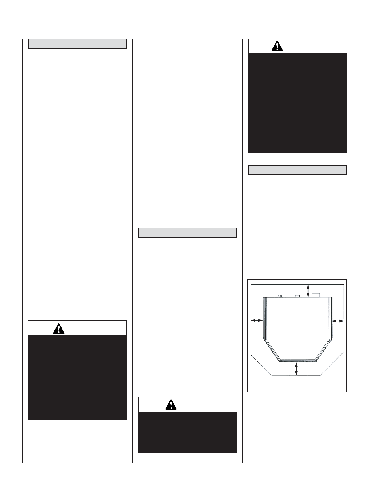
A noncombustible fl oor protector must fully
cover the area beneath the appliance and extend
6” to the front, 6” to the sides, and up to 6” from
the back as illustrated in Figure 1.
Up to * 6” (153 mm)
minimum
6”
(153 mm)
min.
Top View
Floor
Protector
Figure 1 - Floor Protction, Freestanding
*Note: When installed at clearances less than
6”, the fl oor protection is only required to
extend to the wall.
4
NOTE: DIAGRAMS & ILLUSTRATIONS ARE NOT TO SCALE
Page 5

Floor Protection - Profi le® 30 FS-2
The fl oor protector must meet or exceed the minimum thermal requirements as defi ned on this page (see Floor Protection / Hearth Extension
Using Alternate Material As Floor Protector). If the fl oor protection is
to be stone, tile, brick, etc., it must be mortared or grouted to form a
continuous noncombustible surface. If a chimney connector extends
horizontally over the fl oor, protection must also cover the fl oor under
the connector and at least 2” (51 mm) to either side.
The fl oor protector must fully cover the area beneath the appliance and
extend 6” to the front, 6” to the sides, and 6” from the back as shown
in Figure 1 (Note: When installed at clearances less than 6”, the fl oor
protection is only required to extend to the wall).
Floor Protection / Hearth Extension Using Alternate Material As
Floor Protector - All Models
Note: Also see Floor Protection above for free-standing models and Hearth
Requirements, Page 7 for the fi replace insert model.
The hearth pad or alternate material used as a fl oor/hearth protector
must be constructed of a durable noncombustible material having an
equal or better thermal conductivity value (lower k value) of k = .84 BTU
2
/ IN FT
HR °F or a thermal resistance that equals or exceeds r = 1.19
HR °F FT2 IN/BTU with a minimum thickness of 3/8”. With these values,
determine the minimum thickness of the alternate material required using
the formula(s) and the table shown here (see Table 1).
Note: Any noncombustible material having a minimum thickness of 3/8”
(10 mm) whose k value is less than .84 or whose r value is more than
1.19 is acceptable. If the alternate material used has a higher k value
or lower r value will require a greater thickness of the material used. In
some cases, if the k value is less or the r value higher, a thinner material
may be used.
Methods of determining fl oor protection equivalents:
To determine the thickness required for the alternate material when
either the "k" value or "r" value is known, use either the k formula or r
formula.
Example: If Micore 300 is to be used for the fl oor protection, how thick
must this material be?
k
= k value per inch of alternate material
M
rM = r value per inch of alternate material
TM = minimum thickness required for alternate material
T
= standard thickness of the alternate material
S
= k value per inch of listed material
k
L
rL = r value per inch of listed material
= minimum thickness of listed material
T
L
Note: An asterisk "*" indicates, it is a value taken from Table 1.
Using the k formula:
** If the hearth extension material(s) that is intended to be used is NOT listed
on Table 1, the material can still be used if the material(s) is noncombustible.
However, the manufacturer of the material must provide either the listed k-value
per inch or r-value per inch with listed thickness so that the minimum thickness
required for the hearth can be calculated (per instructions on this page and/or
as specifi ed in the NFI Certifi cation Manuals).
Note: Also see NFI (National Fireplace Institute) Certifi cation Manuals showing other acceptable calculation methods and acceptable alternate materials
which can be used.
NOTE: DIAGRAMS & ILLUSTRATIONS ARE NOT TO SCALE
Minimum k-value (per Inch) of Specifi ed min.
thickness of = alternate material (k
alternate k-value (per inch) of listed
material (T
(inches) = kM x TL
T
M
) of listed material (kL) material (TL)
M
) x thickness
M
*.84
(inches) = *.46 x .375"
T
M
*.84
.205 (inches)= .547 x .375"
Answer - The minimum required thickness of the Micore 300 is .205," therefore round up to nearest standard thickness available which is 1/4."
Using the r formula:
Minimum r-value (per Inch) Specifi ed min.
thickness of = of listed material x thickness
alternate r-value (per inch) of listed
material of alternate material material
(inches) =
T
M
r
(inches) = *1.19 x .375"
T
M
r
L x T
M
L
* 2.17
.205 (inches)= .548 x .375"
Answer - The minimum required thickness of the Micore 300 is .205," therefore round up to nearest standard thickness available which is 1/4."
Listed Material
k (per inch) r (per inch) Listed Min.Thickness
Listed Material .84
** Approved Alternate Materials for Floor/Hearth Protection
AlternativeMaterials Thermal Values MinimumThickness
Kaowool M Board .47 2.13 .21" (1/4")
Micore 160™
U.S. Gypsum
Micore 300™
U.S. Gypsum
Durock™ Cement Board
U.S. Gypsum
Hardibacker™ 1.95 .513 .87" (7/8")
Hardibacker 500™ 2.30 .435 1.03" (1")
Cultered Stone Hearthstone™
Wonderboard 3.23 .31 1.44" (1-1/2")
Super Firetemp M
Johns-Manville
Super Firetemp L
Johns-Manville
Face brick 9.00 .111 4.02" (4")
Common brick 5.00 .20 2.23" (2-1/4")
Cement mortar 5.00 .20 2.23" (2-1/4")
Ceramic tile 12.5 .08 5.58" (5-5/8")
Marble ~11 ~.09 4.91" (4-7/8")
K
L
k (per inch)
K
M
.35 2.86 .16" (1/8")
.46 2.17 .21" (1/4")
1.92 .52 .86" (7/8")
2.82 .355 1.26" (1-1/4")
.61 1.64 .27" (1/4")
.54 1.85 .24" (1/4")
1.19
r
L
r (per inch)
r
M
3/8" (.375")
T
L
(rounded to nearest 1/8 inch)
Min. Thickness
T
M
Table 1
5
5
Page 6
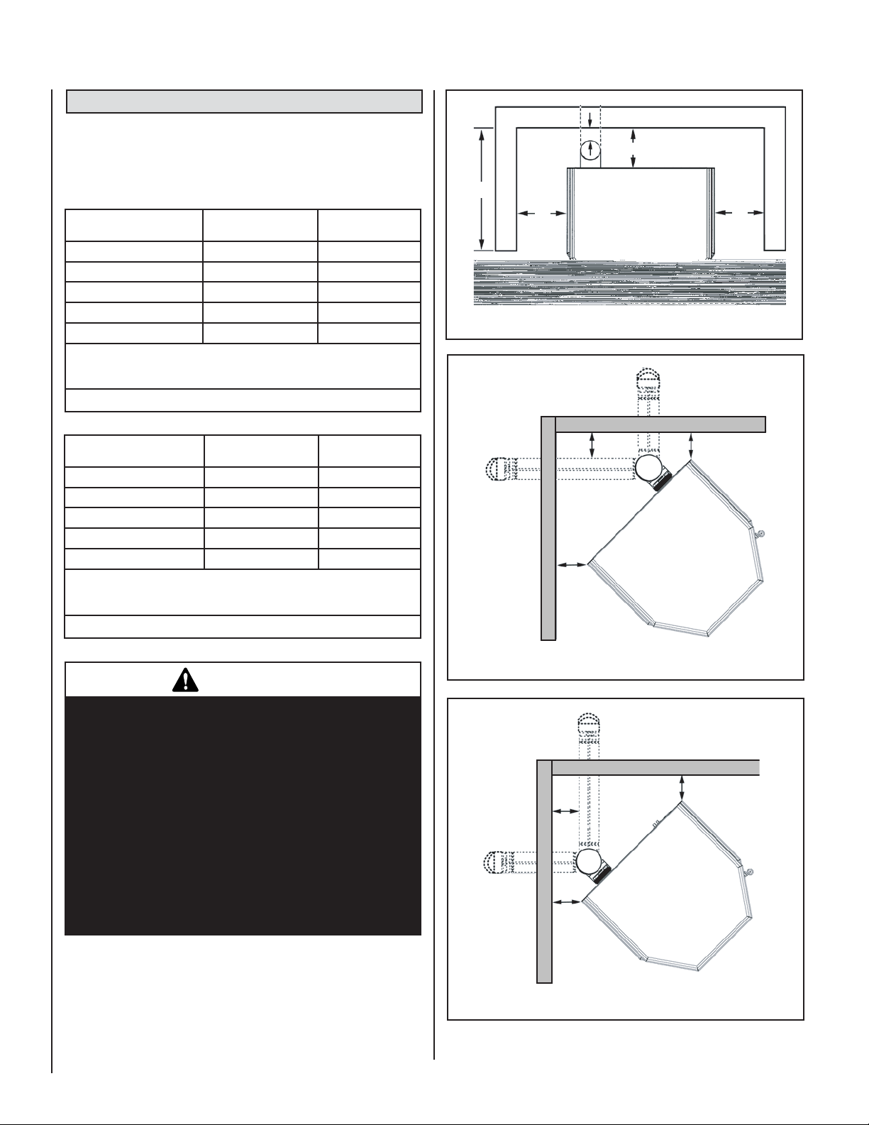
CLEARANCES - FREE-STANDING MODELS
Models: Profi le® 20 FS-2 and Profi le 30 FS-2
Standard residential or manufactured home installation. These appliances
require the following minimum clearances to combustibles:
Profi le 20 FS-2
A - Sidewall to unit 4” (102 mm) 4” (102 mm)
B - Backwall to unit * 2” (51 mm) 9” (229 mm)
C - Sidewall to unit Corner * 2” (51 mm) * 2” (51 mm)
D - Max. Depth of Alcove
E - Flue to Wall 3” (77 mm) 3” (77 mm)
Measured to fuel hopper lid in alcove.
Minimum Alcove Measurements - Height 48” (1220 mm) x Width 31”
(788 mm) x Maximum Depth 16” (406 mm)
Horizontal Flue –
Directly Through Wall
24” (610 mm)
Interior Vertical
Flue
24” (610 mm)
Table 2 - Minimum Clearances To Combustibles
Profi le 30 FS-2
A - Sidewall to unit 6” (153 mm) 6” (153 mm)
B - Backwall to unit * 2” (51 mm) 9” (229 mm)
C - Sidewall to unit Corner * 2” (51 mm) * 2” (51 mm)
D - Max. Depth of Alcove
E - Flue to Wall 3” (77 mm) 3” (77 mm)
Measured to fuel hopper lid in alcove.
Minimum Alcove Measurements - Height 48” (1220 mm) x Width 31”
(788 mm) x Maximum Depth 16” (406 mm)
Horizontal Flue –
Directly Through Wall
16” (407 mm)
Interior Vertical
Flue
16” (407 mm)
Table 3 - Minimum Clearances To Combustibles
Combustible
E
B
D
Combustible
A
Figure 2 - Rear Wall or Alcove, Profi le
Combustible
E
Combustible
C
A
20 FS-2 and Profi le 30 FS-2
C
Combustible
IMPORTANT
•
Minimum clearances specifi ed may not allow
for ease of operation and maintenance (please
take this in to account when planning the installation). If installed to the minimum clearances,
removal of the appliance may be necessary for
servicing.
•
Recommended clearance zone from the front
of the appliance to combustibles is 4 feet minimum.
•
The certifi ed back wall clearance as shown on the
listing label is 1” (see Safety / Listing Label) but
for proper hopper lid operation in corner and parallel installations a 2” clearance is required.
6
Figure 3 - Corner, Profi le
Figure 4 - Corner, Profi le
NOTE: DIAGRAMS & ILLUSTRATIONS ARE NOT TO SCALE
20 FS-2
E
Combustible
C
30 FS-2
Combustible
C
Page 7
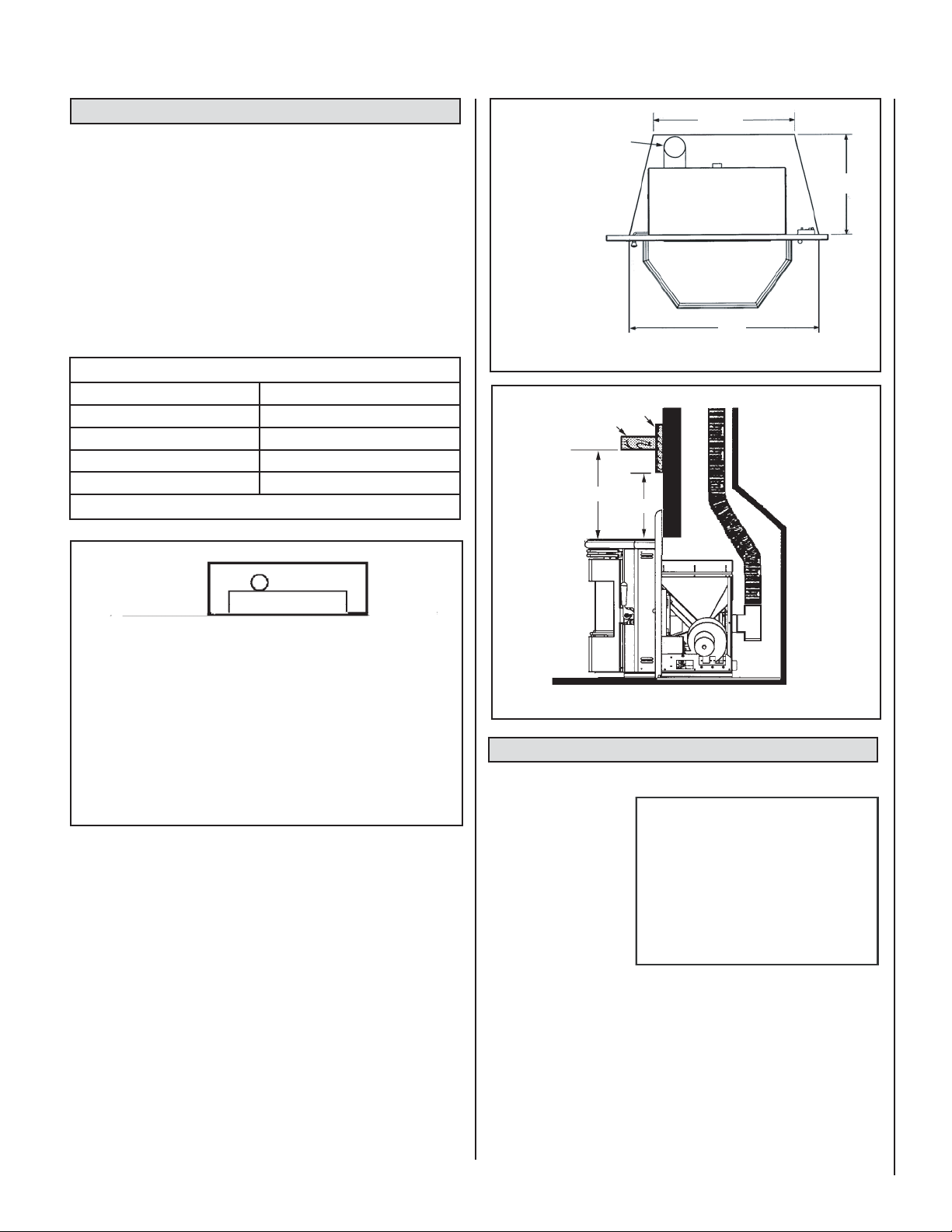
CLEARANCES AND HEARTH PROTECTION - INSERT
Model Profi le
®
30 INS-2
24-5/8”
Clean-Out
Tee
In the USA and Canada, the area below and directly in front of the Profi le
30 INS-2 fi replace insert must be an approved fi replace hearth or protected
by a non-combustible hearth / fl oor protector with a minimum thickness
of 3/8” which has a thermal conductivity of k (per inch) = .84 or lower
value (better thermal protection) or resistance of r (per inch) = 1.19 or
higher value. See Floor Protection / Hearth Extension Using Alternate
Material As Floor Protector on Page 5 which explains minimum thermal
protection requirements.
The protected area must extend 6” to the front of the face of the Profi le
30 INS-2.
Profi le 30 INS-2
A - Insert to side wall 6” (153 mm)
B - Insert to side trim 1” (26 mm)
C - Hearth extension 6” (153 mm)
D - Insert to mantel 18” (458 mm)
E - Insert to top trim 1” (26 mm)
Table 4 - Minimum Clearances To Combustibles
Profi le 30-2 INS
Side Wall
Trim
Profi le 30-2 INS
Recommended
clearance zone
from the front of
the appliance to
combustibles is 4
feet minimum.
Top View
32”
Figure 6 - Fireplace Firebox Minimum Size, Insert
Mantel
D
Trim
E
Profi le
Side View
®
30-2 INS
17-3/4”
Top View
B
A
Hearth / Floor
C
Protection
Figure 5 - Clearances, Insert
Masonry And Factory Built Fireplaces – Profi le 30 INS-2
The model Profi le 30 INS-2 is approved for installation into a solid fuel
burning fi replace, either a masonry fi replace (built to UBC 37 or ULC S628
standards) or an approved factory-built / zero clearance fi replace (built
to UL 127 or ULC S610 standards). See Pages 17 and 18 for additional
information on venting.
Minimum Fireplace Firebox Size
Height ...............................................20-1/8” (512 mm)
Width @ Front ...................................32” (814 mm)
(extends back 1-1/2”)
Width @ back ...................................24-5/8” (626 mm)
Depth ................................................17-3/4” (452 mm)
NOTE: DIAGRAMS & ILLUSTRATIONS ARE NOT TO SCALE
Figure 7 - Mantel and Trim Clearances, Insert
FIREPLACE WARNING LABEL
(provided in accessory package)
When installing the
Profi le 30 INS-2 into a
factory built fi replace or
heatform, the air fl ow
within and around the
fi replace shall not be
altered by the installation of the insert (i.e.
DO NOT BLOCK louvers
or cooling air inlet or
outlet ports, circulating
air chambers in a steel
fi replace liner or metal heat circulator). The factory built fi rebox must
accept the insert without modifi cation other than removing bolted or
screwed together pieces such as smoke shelf / defl ectors, ash lips,
screen or door tracks and damper assemblies. Any fi replace component, which is removed, must be retained so they can be reinstalled
to restore the fi replace to its original operating condition. The removal
of any part must not alter the integrity of the outer shell of the preengineered fi replace cabinet in any way. A Warning Label (provided
with appliance) must be installed in the fi replace fi rebox so that it shall
be visible upon removal of the fi replace insert (Warning Label shown
in gray above). Use RTV high Temperature Silicone as an adhesive to
affi x the warning label.
IF THIS FIREPLACE INSERT IS BEING
INSTALLED INTO A FACTORY BUILT FIREPLACE,
THIS LABEL MUST BE PERMANENTLY
ATTACHED TO THE FIREBOX OF THE
FACTORY BUILT FIREPLACE.
WARNING
THIS FIREPLACE HAS BEEN ALTERED TO
ACCOMMODATE A FIREPLACE INSERT AND
SHOULD BE INSPECTED BY A QUALIFIED
PERSON PRIOR TO RE-USE AS A
CONVENTIONAL FIREPLACE.
7
Page 8
CAUTION
The fi replace in which the Profi le
30 INS-2 is to be installed must be
thoroughly cleaned if it has been
used to burn wood or synthetic
logs. Have the chimney and all
inside surfaces of the fi replace
brushed and vacuumed so that
no soot, embers, or loose combustion deposits can be drawn
into the heat circulation blower
and blown into the living area.
If any portion of the chimney
system shows signs of structural
or mechanical weaknesses, such
as: cracks, leaky joints, corroded
or warped surfaces, the faulty
portion must be repaired or
replaced prior to installing this
appliance.
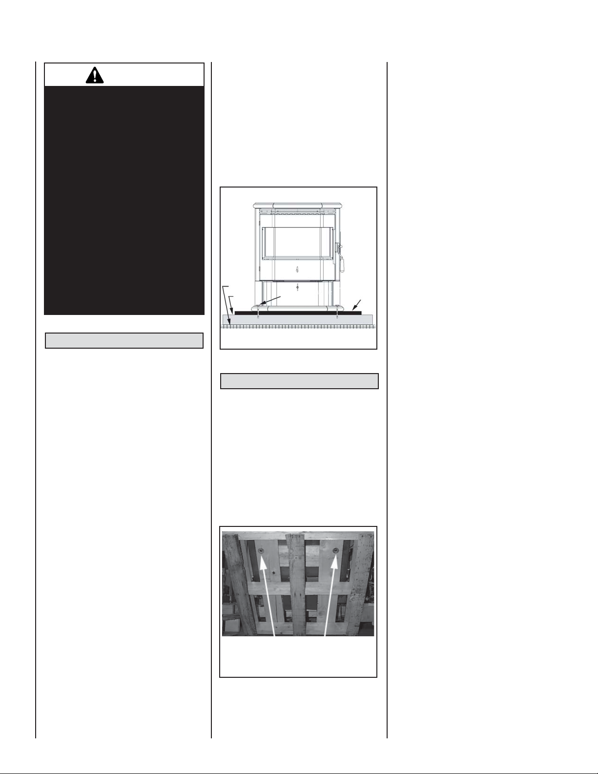
MANUFACTURED HOME INSTALLATION
Free-Standing Models – Profi le 20 FS-2 and
Profi le 30 FS-2
In addition to the standard installation instructions, the following instructions may be required
by local, state or federal building codes:
• The stove must be permanently bolted to
the fl oor.
• An outside air inlet must be provided for
combustion and be unrestricted while unit
is in use. Use a galvanized or stainless steel
pipe for the duct (the outside air inlet on the
stove is 1-5/8” diameter).
• Stove must be permanently electrically
grounded to the steel chassis of the home.
The location selected for ground attachment to the stove must be dedicated for
this purpose. Grounding must comply with
NFPA-70 standards, CSA C22.1 in Canada,
as well as any local codes.
• See Pages 10 through 16 for additional
information on venting requirements.
• Do not install appliance in a sleeping
room.
• The structural integrity of the manufactured
home fl oor, walls, ceiling and roof must be
maintained.
Manufactured Home Exhaust Vent Pipe Installation Guidelines
Use only “PL” pellet vent pipe listed to UL 641
and ULC S609. The pipe should extend at least
3 feet above the part of the roof through which
it passes. The top of the pipe should be at least
2 feet above the highest required elevation of
any part of the manufactured home within 10
feet of the pipe (see Page 12, Manufactured
Home Chimney Height Requirements).
8
If the exhaust vent exits the manufactured home
at a location other than the roof, and exits at
a point 7 feet or less above the ground level
on which the manufactured home is position
a guard or method of enclosing the pipe shall
be provided at the point of exit for a height of
up to 7 feet. The openings, if any, in this guard
shall not allow a 3/4” rod to pass through. A
1/2” rod could pass through but should not be
able to touch the pipe when inserted through
the opening a distance of 4 inches.
Chassis
Floor
Bolt
Floor
Protector
Figure 8 - Manufactured Homes
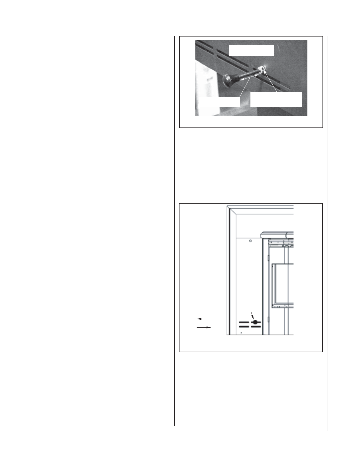
INSTALLATION
Removing Appliance From Pallet
1. After removing the packaging from the
stove, lift the hopper lid, and remove all
prepackaged items that were shipped in
the hopper. Next, open the stove door and
remove all prepackaged items.
2. Using a 7/16” socket or open end wrench,
remove the bolts which secure stove to
pallet. The bolts are located on the underside
of the wooden pallet.
Remove the three bolts from
underneath the pallet.
Figure 9 - Removing from Pallet
NOTE: DIAGRAMS & ILLUSTRATIONS ARE NOT TO SCALE
Installation Check List
It is strongly recommended that you have an
authorized Lennox Hearth Products dealer
install your stove. If you install your stove
yourself, you should review your installation
plan with an authorized Lennox Hearth Products dealer.
Check list:
Check off each item as you proceed with the
installation process.
Read the ENTIRE stove installation section
fi rst
Read the Insert or Free-Standing section
(whichever applies).
Determine the appropriate measurements
and locations for your installation.
Follow the installation directions in this
manual that are applicable to your model
of free-standing stove or fi replace insert.
Be sure to prefi t all items before you install,
fasten, or set up the appliance perma-
nently.
Prior to lighting your appliance:
Review the safety precautions section.
Review the pellet FUEL section.
Review and follow the Operating Instruc-
tions.
Plug power cord connector into correspond-
ing connector on the back of appliance (see
Figures 12 through 16 on Page 10 showing
connector locations).
Note: Profi le 30 INS-2 – Route power cord
behind side surround panel.
After you have begun operation of your
appliance:
Review the routine cleaning / maintenance
information.
Enjoy the warmth from your new Lennox
Hearth Products pellet appliance!
It is important to level the appliance. When
installing the insert model, in some installations such as a recessed fi rebox fl oor (if
the existing fi replace fl oor is lower than the
hearth), install the 2 leveling bolts (1/4-20 x
3” long) into the threaded holes at the rear
base of the Profi le 30 INS-2. Adjust bolts until
appliance is level.
Page 9
Installing Surround Assembly - Profi le
®
30 INS-2
(to be done after venting system is installed) This fi replace insert
requires surround panels (a set of metal panels that enclose the fi replace
opening when fi tted together). There is also a trim assembly that frames
the surround assembly to give it an attractive fi nished appearance. Put
the surround assembly together according to the following instructions
(ref. Page 41).
Damper is factory set to a
gap as specifi ed below.
1. Remove panels and trim brackets from package. Be careful not to
discard the “L” shaped trim brackets which are attached to the surround wrapping.
2. Open the hopper lid of the insert so it is out of the way for when panels
are installed.
3. Install the control board onto the right side panel (with door) using
the TEK screw (#8 x 1/2”) provided.
4. Position the power cord so that it will be behind either the right or left
side surround panel when they are installed.
5. Install right side surround panel onto right side of the insert body by
sliding the 2 fl anges on side of panel into corresponding slots on the
insert.
6. Connect the wiring harness from the insert into corresponding connector on control board.
7. Locate damper rod on left side of the insert. Rotate angled arm of rod
so it is pointing down. Remove damper knob and set aside.
8. Install the left-hand panel onto the left side of the insert body by
sliding the 2 fl anges on side of panel into corresponding slots on the
insert.
9. Reach behind left surround panel and rotate damper arm so that end
is inserted into the upper right hand slot of left surround panel (see
Figure 11).
10. Reinstall damper knob by threading it onto end of damper rod.
11. Set the top surround panel in place over the two side panels. Position the 2 tabs on bottom of top surround panel so they slide into
corresponding clips on the insert. Connect the top surround panel to
the side panels by pressing pins from side panels into corresponding
holes on top panel.
12. Remove the surround trim from its packaging. Assemble it together
using the corner keys (“L” shaped brackets) provided. Slide assembled
trim over the top surround panel and slide it down over the side
panels.
13. Push the Profi le 30 INS-2 back into place so the surround assembly
is fl ush with the face of the hearth.
1-5/8” - Profi le 30 FS-2
2” - Profi le 20 FS-2
To adjust, use a 3/32” allen
wrench (provided with stove)
to loosen set collar.
Figure 10 - Damper Adjustment, Free-Standing Models
Damper Installation - Model: Profi le 30 INS-2
Install damper rod knob as illustrated (see Figure 11) and explained on
this page (see Installing Surround Assembly – Profi le 30 INS-2).
Adjustment Procedure - Model: Profi le 30 INS-2
The damper knob should be positioned in the center of the oblong slot
for the average installation (see Figure 11). If more or less air is needed,
then adjust in 1/4” increments until optimum combustion air fl ow is
achieved (see Damper Adjustment Guidelines on Page 21).
Profi le 30-2 INS
For less air, slide
damper knob to the right
(or) for more air, slide
knob to the left.
Left
Surround
Panel
Damper Location, Installation And Adjustment
Damper Air Control Handle - Models: Profi le 20 FS-2 and Profi le 30 FS-2
(located on right side panel on model Profi le 20 FS-2 and on the left side
panel on Profi le 30 FS-2)
Adjustment Procedure- Models: Profi le 20 FS-2 and Profi le 30 FS-2
Loosen setscrew on set collar (see Figure 10), then adjust in 1/4” increments until optimum combustion air fl ow is achieved. For less air push
in and for more air pull out. After adjustment, position set collar against
side panel and tighten setscrew.
NOTE: DIAGRAMS & ILLUSTRATIONS ARE NOT TO SCALE
More Air
Damper Knob
Less Air
Figure 11 - Damper Adjustment, Inserts
Hopper Cover Installation
Model: Profi le 30 INS-2
Install the hopper cover over the hopper using the 11 screws provided
as follows:
1) Align the 11 slots on the hopper cover with the corresponding 11
holes on the back and sides of the hopper.
2) Loosely install the 11 screws through the slots into the corresponding
holes in hopper (screws are provided in the accessory package).
3) Position the hopper cover to the highest position that will allow for
proper fi t into the fi replace opening, then tighten screws.
9
Page 10

Thermostat Installation:
Note: Always Disconnect Power Before Performing The Thermostat Installation.
Leave jumper on, if
thermostat is NOT used
A 24 volt wall thermostat and 20 feet of 18-gage
thermostat wire is included in the accessory
package. It is recommended that the thermostat
and thermostat wire be installed by an authorized Lennox Hearth Products dealer.
Installation Steps:
1. Unplug stove power cord from the wall
outlet.
2. Locate the thermostat terminal block (see
Figures 12 through 16).
3. Loosen the two terminal screws on the
terminal block and remove the jumper.
4. Connect the two wires from your thermostat
to the terminals (one per terminal). Ensure
that the purple wires from the harness
remain connected to the terminal block
and tighten the terminal screws. Make
sure the wires are fi rmly connected to the
thermostat.
5. Plug in the stove and you are ready to operate
with your thermostat!
Note: See Wiring Diagram on Page 32.
IMPORTANT: IF THE WALL THERMOSTAT
PROVIDED IS NOT USED, THE JUMPER IS
REQUIRED FOR THE STOVE TO OPERATE.
Jumper
Remove jumper if Thermostat IS to be used
Thermostat wires
Terminal
Block
Jumper
and purple wires
from wire harness
will connect to
these 2 terminals
Figure 13 - Terminal Block - Type B
Terminal Block
Figure 16 - Terminal Block, Profi le 30 INS-2
VENTING REQUIREMENTS
It is recommended that only an authorized
dealer install your pellet stove. The specifi ed
installation requirements must be followed to
ensure conformity with both the safety listing
of the appliance and local building codes. All
clearances, installation instructions and precautions specifi ed by the vent manufacturer must
be followed.
Leave jumper on, if
thermostat is NOT used
Jumper
Remove jumper if Thermostat IS to be used
Terminal
Block
Jumper
Thermostat wires
and purple wires
from wire harness
will connect to
these 2 terminals
Figure 12 - Terminal Block - Type A
Terminal Block
Figure 14 - Terminal Block, Profi le
Model: Profi le 30 FS-2
Terminal Block
®
20FS-2
Figure 15 - Terminal Block, Profi le 30 FS-2
Selecting a Location (Free-Standing Models)
Review the appliance clearance requirements
before installing the venting system (see Page
6). Position the appliance far enough away
from walls to allow adequate room for servicing.
Choose the appliance location with the least
amount of interference with the house framing,
plumbing, wiring, etc.
Preferred Vent Confi guration
For the best performance, we recommend a vent
run design which runs vertically and terminates
above the roof line. This design will allow natural
draft to improve the fl ow of fl ue gases and will
aid in combustion and stove performance.
Type of Pipe
This stove requires type “PL” vent pipe (pellet
vent pipe, sometimes referred to as “L-Vent
pellet vent”), listed to UL 641 or ULC S609. Connect the pellet vent pipe or the “tee” to the fl ue
collar using a minimum of three screws and seal
as specifi ed in “Pipe / Liner Joint Requirements”
on Page 11. Do not use class B gas chimney or
single wall chimney as a substitute.
10
NOTE: DIAGRAMS & ILLUSTRATIONS ARE NOT TO SCALE
Page 11

Size of Pipe
These pellet appliances are approved for use
with the following vent sizes: 3” (75 mm)
standard, or 4” (100 mm), see Page 13 - for
determining correct size vent). When 4” pipe
is used: for horizontal vent installations use a
3” (75 mm) to 4” (100 mm) adapter - available
from vent manufacturer. For vertical installations use a 3” (75 mm) to 4” (100 mm) “tee”
- available from vent manufacturer.
Offsets
In every installation, a single or double clean-out
“tee” is recommended for every ninety-degree
offset (this tee will help collect ash residue and
will allow for routine cleaning without the need
to disconnect sections of pipe).
Note: Offsets and horizontal runs accumulate
fl y ash and soot which reduces the exhaust fl ow
and performance of the stove.
• Total Offsets in venting system should not
exceed 270° total in direction change.
• Horizontal Runs - The maximum total
horizontal run must not exceed 10 feet
(3.1 meters).
• Horizontal run of pipe requires 1/4” (7 mm)
rise per foot.
Pipe Clearances / Requirements
See pipe manufacturers instructions for installation of venting components and clearances.
Follow pipe manufacturers installation precautions for passing pipe through a combustible
wall or ceiling (i.e. use an approved thimble).
Note: Pellet vent pipe requires 3” (75 mm)
clearance from outside of pipe unless otherwise
specifi ed by vent manufacturer - all diameters:
3” (75 mm) and 4” (100 mm). A support bracket
must be installed every 4 feet (1.2 m) of pellet
vent pipe on the exterior wall of the house unless
otherwise specifi ed by vent manufacturer.
Pipe / Liner Joint Requirements
Connection to Masonry Chimney through a
Wall (Free-Standing Models)
Be sure to verify the construction of a masonry
chimney, as it may have combustible framing.
Approved liner when relining Masonry or Factory Built Fireplaces is 2100HT (degree F.) liner
listed to UL 1777 or ULC S635.
Connection to an Existing Class A Chimney
(Free-Standing Models)
A chimney adapter can be used to make the
connection from 3” (75 mm) or 4” (100 mm)
pellet vent pipe (listed to UL 641 or ULC S609)
to existing UL chimney system. Verify with the
pipe manufacturer that your pipe brands will
interconnect.
Horizontal Vent Installations
On all horizontal vent installations (short,
horizontal runs with no vertical pipe); care
should be taken when choosing a location for
terminating the vent. It is not recommended
to directly vent the exhaust on the prevailing
wind side of the house. It is recommended that
when an appliance is vented directly through
a wall, a minimum of 8 feet (2.5 m) of vertical
pipe should be installed to create some natural
draft. This will reduce the possibility of smoke
or odor entering the dwelling during appliance
shutdown or loss of power.
Vent Termination
Do not terminate vent in an enclosed or
semienclosed area such as: carports, garage,
attic, crawl space, under a deck, porch, narrow
walkway, closely fenced area, or any location
that can build up a concentration of fumes such
as a stairwell, covered breezeway etc.
Vent surfaces can get hot enough to cause
burns if touched. Adults should supervise
children when they are in the area of a hot
stove. Non-combustible shielding or guards
may be required.
B. Not less than 4 feet (1.2 meters) below, 4
feet (1.2 meters) horizontally from or 1 foot
(3.1 meters) above any gravity air inlet (door,
window, etc.) which fl ue gases could reenter
the dwelling.
C. Not less than 2 feet (.6 meters) from combus-
tible materials such as an adjacent buildings,
fences, protruding parts of the structure,
roof overhang, plants and shrubs, etc. and
not less than 7 feet (2.1 meters) above
grade when located adjacent to the public
sidewalks (access). The fi nal termination of
the exhaust system must be confi gured so
that fl ue gases do not jeopardize the safety
of people passing by, overheat combustible
portions of nearby structures or enter the
dwelling.
D. Not less than 3 feet (.92 meters) below an
eave (maximum overhang of 3 feet (.92
meters) or any construction that projects
more than 2 inches (51 mm) from the plane
of the wall.
E. The distance from the bottom of termination
to grade is 12 inches (305 mm) minimum.
This is conditional upon plants and nature
of grade surface: Be careful to choose a
location for the vent termination which
does not expose people or shrubs to high
heat from the exhaust gases. The exhaust
gases are not hot enough to ignite grass,
plants and shrubs located in the vicinity of
the termination although they should be a
minimum of 3 feet (.92 meters) away. The
grade surface under the termination must
not be a lawn.
F. Since sparks may escape from the exhaust
pipe of any stove, use caution when
positioning the vent pipe. Refer to pipe
manufacturer’s instructions when installing
and terminating the exhaust. The vent pipe
should be horizontal and never run the pipe
in a downward direction (recommend a 1/4
inch [7 mm] rise per foot horizontal).
Notes:
All pipe joints must be secured with a minimum
of 3 screws. ALL horizontal joints must be
sealed gas-tight (air tight, sealed connection).
Use RTV high temperature silicone or Interam
to provide a complete seal at the fl ue collar
and on all joints.
Termination Cap: The termination of the outside
chimney of the pellet stove shall be located in
accordance with the following:
A. Higher than 3 feet (.92 meters) above any
forced air inlet (air conditioner, etc.) located
within 10 feet (3 meters).
NOTE: DIAGRAMS & ILLUSTRATIONS ARE NOT TO SCALE
• It is not recommended to terminate exhaust
vent on the prevailing wind side of the
house.
• It is not recommended using a termination
cap with a screen (fl y ash can collect in a
screen resulting in blockage).
11
Page 12
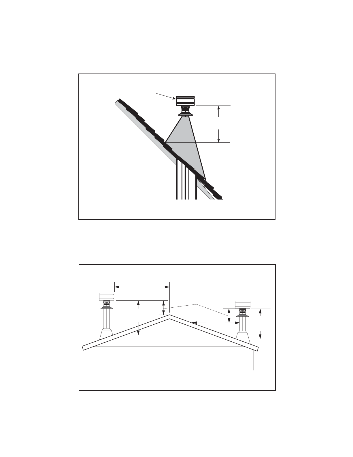
Chimney Height Requirements - Site-Built Residential Home
The vent termination height required is - USA, 1-foot minimum; Canada, 3-feet minimum above the roof penetration point as illustrated below (Ref.
USA - National Standard, NFPA 211 and Canada National Standard CSA B365-01. Check with your local building offi cial for additional requirements
for your area.
Termination Cap Must Be
Listed To UL 641 or ULC S609
USA 1 Foot Minimum
CANADA 3 Feet Minimum
Termination height is measured
above the highest point where it
passes through the roof surface.
Figure 17 - Site-Built, Residential Home Chimney Height Requirements
Chimney Height Requirements - Manufactured Homes
The chimney must extend 3 feet (.92 meters) above the level of roof penetration and a minimum of 2 feet (.61 meters) higher than any roof surface
within 10 feet (3 meters) (see below). Check with your local building offi cials for additional requirements for your area.
Requires A Listed
Termination Cap *
m = meter
mm = millimeter
Less than
10 Feet (3 m)
3 Feet (914 mm)
Minimum
Top Of Flue Must Be 2
Feet Higher Than Any Part
Of Roof Within 10 Feet
Horizontal
2 Feet (610 mm) Min.
10 Feet
(3 m)
Top Of Flue Must
Be 3 Feet Higher
Than Highest
Point Of Roof
Penetration
3 Feet
(914 mm)
Min.
Figure 18 - Manufactured Home Chimney Height Requirements
To pass inspection in nearly any jurisdiction, the chimney must meet both safety and exhaust fl ow requirements. The (3 feet by) 2 feet by 10 feet rule
applies to both masonry and factory built chimneys
* Ref. NFPA 211, Vents installed with a listed cap shall terminate in accordance with the terms of the cap’s listings.
12
NOTE: DIAGRAMS & ILLUSTRATIONS ARE NOT TO SCALE
Page 13
Determining Size Of Pipe To Install
To determine what diameter pipe to use in an installation (3” or 4”), fi rst
fi nd the “equivalent pipe length” using the following guidelines, then plot
this Figure and the altitude on the chart.
30
4 Inch Diameter Only
20
Fill out the installation chart, and calculate your total equivalent pipe
length. After you have the total equivalent pipe length, use the Pipe
Selection Chart below to determine if your installation requires 3” or 4”
exhaust pipe.
Installation Chart
Type of Pipe # of Elbows or
Feet of pipe
90° Elbows /
Tee (A & G)
45° Elbows
(C)
Horizontal
(B & F)
Vertical(E) x .5 Feet
Equivalent Feet Total Equivalent
Feet
x 5 Feet
(1.5 meters)
x 3 Feet
(1 meters)
x 1 foot
(.3 meters)
(.15 meters)
Table 5
Sample Installation Chart
Type of Pipe # of Elbows or
90° Elbows /
Tee (A & G)
45° Elbows
(C)
Horizontal
(B & F)
Vertical(E) 8 x .5 Feet
Feet of pipe
2 x 5 Feet
1 x 3 Feet
3 x 1 foot
Equivalent Feet Total Equivalent
(1.5 meters)
(1 meter)
(.3 meters)
(.15 meters)
Feet
10 Feet
(3 meters)
3 Feet
(1 meters)
3 Feet
(1 meter)
4 Feet
(1.2 meters)
Table 6 - Sample Chart for Figure 16
3 or 4 Inch
10
Equivalent Pipe Length (Feet)
0
Diameter
0
1
3
2
4
Altitude x 1000 Feet
Figure 19 - Pipe Selection Chart
NOTE: All equivalent pipe styles
shown are standard for all freestanding models.
A- 90 Degree Elbow
B- 1’ Horizontal Pipe
C- 45 Degree Elbow
D- Standoff Braces
E- 8’ Vertical Pipe
F- 2’ Horizontal Pipe
G- 90 Degree Tee
H- Wall Thimble
6
5
7
D
F
9
8
10
B
A
C
E
G
H
Figure 20 - See Sample Installation Chart
NOTE: DIAGRAMS & ILLUSTRATIONS ARE NOT TO SCALE
13
Page 14
14
NOTE: DIAGRAMS & ILLUSTRATIONS ARE NOT TO SCALE
Page 15
Standard Horizontal Installation Confi gurations
®
20 FS-2 and Profi le 30 FS-2
Profi le
3” (75 mm) Minimum
clearance between
wall and pipe. If you
vent to the furthest
wall, the vent pipe
must maintain a 3”
clearance parallel to
the other wall.
Top View Illustration
2" Min.
2" Min.
Wall
Figure 22 - Corner Through the Wall, Profi le 30 FS-2*
Wall
3” (75 mm) Minimum
clearance between wall
and pipe. If you vent to
the furthest wall, the vent
pipe must maintain a 3”
clearance parallel to the
other wall.
Top View Illustration
Top View Illustration
2" Min.
Wall
2" Min.
Wall
Figure 23 - Corner Through the Wall, Profi le 20 FS-2*
2” / 51 mm
Minimum
6” / 152 mm
Minimum
Hearth Pad / Floor Protection
Figure 24 - Parallel Through the Wall, Profi le 20 FS and Profi le 30 FS
* Note: Horizontal run of pipe requires 1/4” (7 mm) rise per foot.
Outdoors
Wall
45 Degree
Elbow
12” (305 mm)
Minimum From
Outer Wall
12” / 305 mm From
Ground or Other Surface
NOTE: DIAGRAMS & ILLUSTRATIONS ARE NOT TO SCALE
15
Page 16

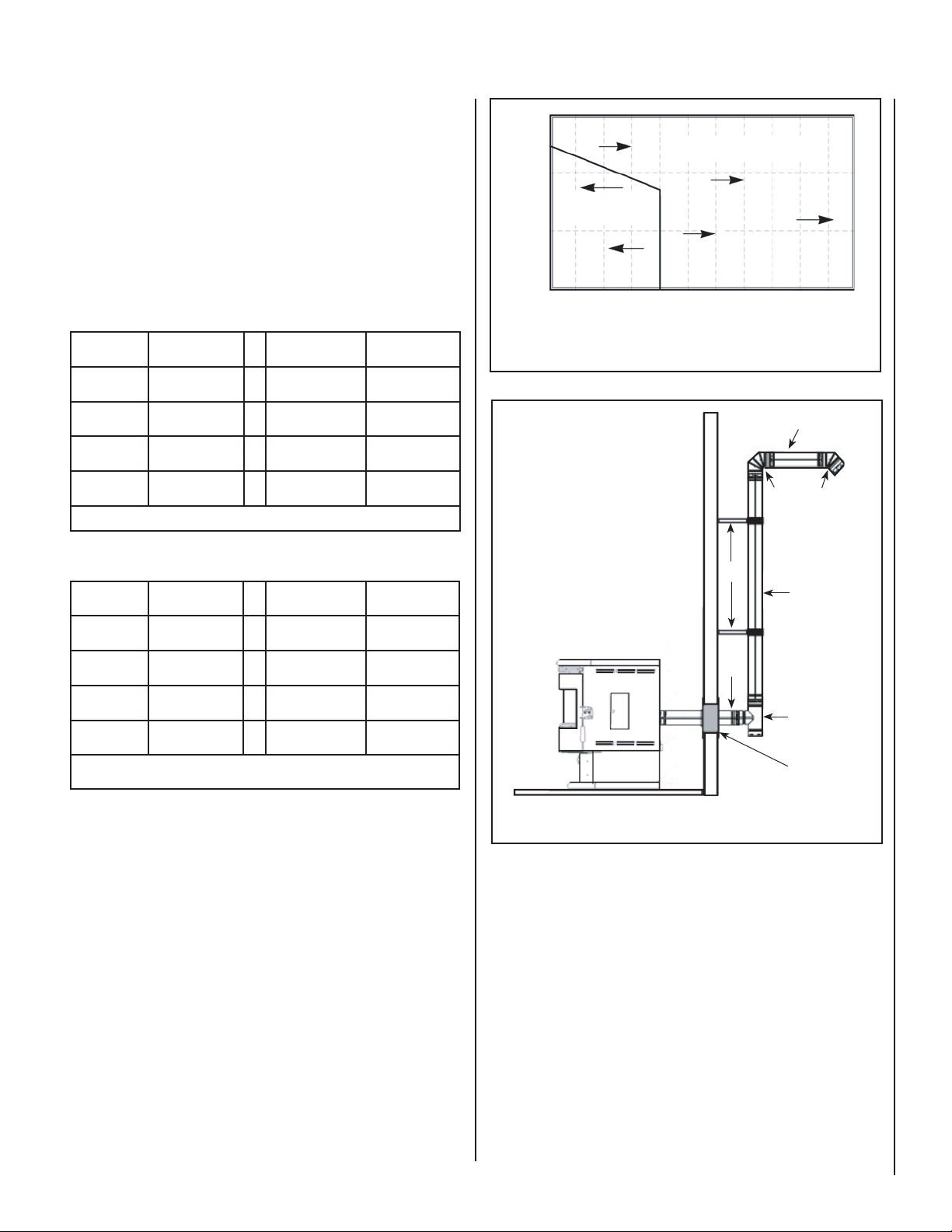
Standard Vertical Installation Confi gurations
Models: Profi le
®
20 FS-2 and Profi le 30 FS-2
These free-standing models may be connected to an existing fl ue or by
installing listed type “PL” vent pipe. If a liner is run all the way to the
top of the existing chimney, the existing fl ue should be sealed with a
steel plate. Start a vertical run with a Tee at the back of the stove. Other
options are illustrated below.
Preferred Installation – Vertical Vent Through the Roof
This venting confi guration allows for the best stove performance. The
vertical pipe promotes natural draft and with the chimney inside the
dwelling, the fl ue gases stay warm, thus rising at a consistent rate.
Note: See Page 12 for Vent Termination Requirements
Figure 25 - Exterior Vertical Vent
Wall Straps
Required Every
4 feet Minimum
Flashing
Listed Rain Cap
3”
Min.
Clean-
out
Tee
Figure 26 - Vertical Vent Through the Roof
16
Optional Complete
Liner and Listed
Termination Cap
Optional
Clean-Out
Access Door
Figure 27 - Vertical Vent Into a Masonry Flue
Existing
Chimney Pipe
Pipe Increaser
Extend Pipe to the Top
if Existing Chimney is
Corroded or Damaged
3”
Min.
Figure 28 - Interior Vertical Vent into Class A Chimney
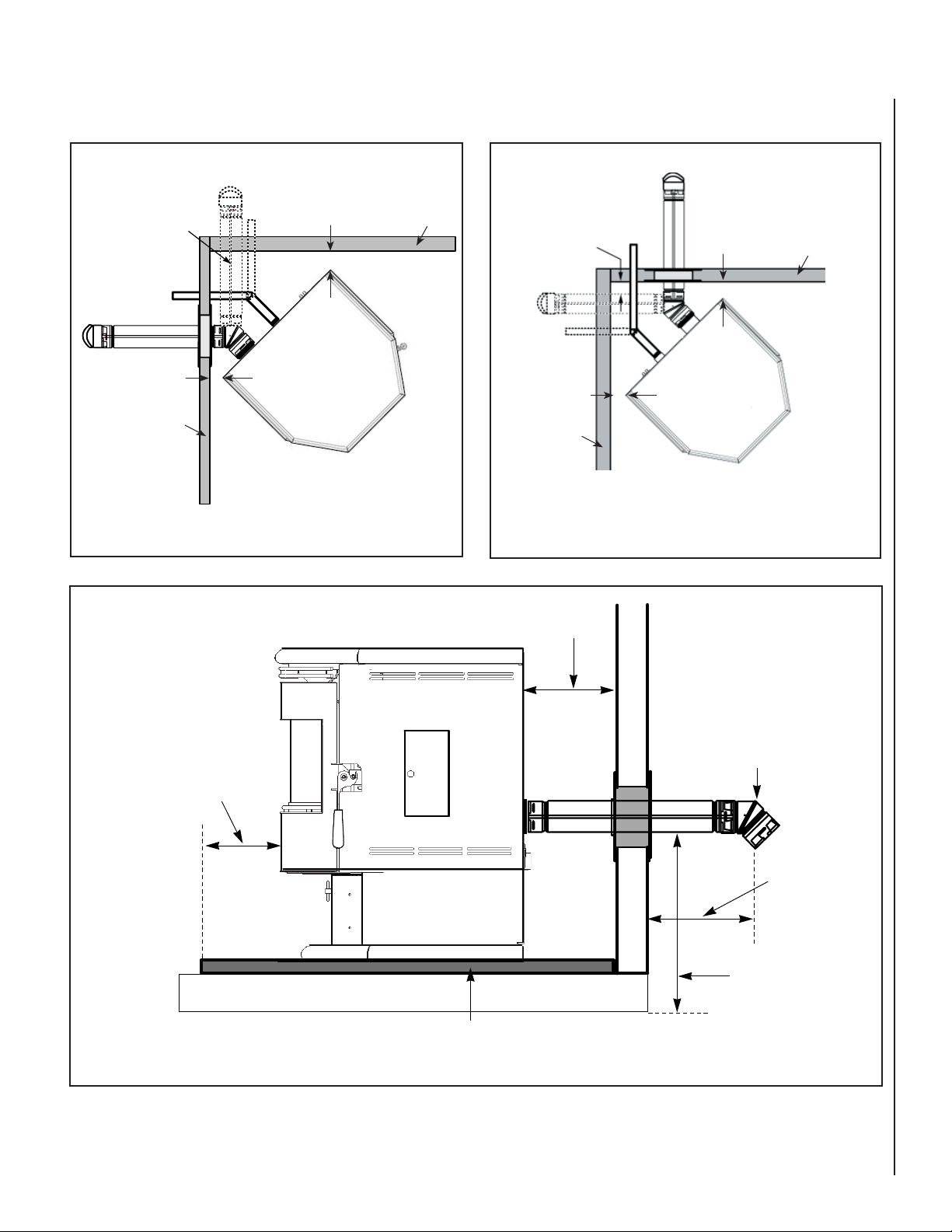
Page 17

Standard Installation Confi gurations Into an Existing Fireplace
Model: Profi le® 30 INS-2
IMPORTANT - Make sure the chimney and fi rebox are clean and free of
soot and ashes before installation begins. Failure to do so may result in
the transfer of soot into the room by way of the room air blower.
(USA only) Venting Into an Masonry Fireplace
In the USA, as a minimum the vent connector from the insert fl ue outlet
must extend a minimum of 18” above the damper and the damper area
must be sealed to prevent dilution air from entering the chimney which
will affect proper drafting of appliance. In Canada, this appliance requires
a full reline when installing into a masonry fi replace.
This pellet insert may be installed into a masonry fi replace (built to UBC
37 or ULC S628 standards) as illustrated on this page. When installing
into a masonry chimney, in the USA it is recommended that the exhaust
vent be extended to the top of the chimney as shown on Page 18 (in
Canada, this is Required). However, in the USA, if the vent pipe does
not extend to the top of the chimney, the vent must extend a minimum
of 18” above the damper. You must seal the damper area so that the air /
exhaust in the chimney cannot communicate with the air in the fi replace
fi rebox (this is a positive fl ue connection. See the following instructions
for one method of sealing fl ue).
(USA and Canada) Direct Connection / Positive Flue Connection
See the following instructions for Approved Methods of Achieving a
Positive Flue Connection.
A qualifi ed installer should evaluate the existing fi replace to determine
the best method for achieving a positive fl ue connection between the
vent pipe or liner and the existing fi replace chimney. The most common
method for achieving a positive fl ue connection in masonry fi replaces is
to secure a seal-off plate (i.e. 22-gage sheet steel) in the fi replace throat
using masonry screws. Other acceptable methods include packing noncombustible material (i.e. rockwool) around the vent pipe or using a fl ue
adapter. Whatever “seal off” method is used must effectively seal the area
to prevent room air passage to the chimney cavity of the fi replace.
Model: Profi le 30 INS-2
NOT ALLOWED IN CANADA
Positive Flue Connection into
a Masonry Fireplace without a
Full Reline
The Profi le 30 INS-2 does not
require a full reline (in USA
only) when installing into a
masonry fi replace, however,
it is recommended to ensure
proper drafting of the appliance.
The vent connector from the
insert must extend a minimum
of 18” above the damper and
the damper area must be sealed
to prevent dilution air from
entering the chimney which
will affect proper drafting of
appliance
The vent pipe must extend a
minimum of 18” above the
damper. The chimney must not
be corroded or damaged in any
way for this type of installation
to be permitted.
A non-combustible seal is
required at the damper area
(to prevent dilution air from
entering the chimney). See
Positive Flue
Connection
Methods on
this page.
18” Min.
(457 mm)
to Mantel
6” Min.
Floor
Protection
Optional
Access
Door
1” Min.
(25 mm)
to Trim
Figure 29 - Direct Connection In A Masonry Fireplace
NOTE: DIAGRAMS & ILLUSTRATIONS ARE NOT TO SCALE
Clean-out
Tee
17
Page 18

Standard Installation Confi gurations Into an Existing Fireplace
Model: Profi le® 30 INS-2
IMPORTANT
Make sure the chimney and fi rebox are clean and free of soot and ashes before installation begins. Failure
to do so may result in the transfer of soot into the room by way of the room air blower.
Model: Profi le 30 INS-2
Full Chimney
Reline (required when
installing into a Factory
Built Fireplace)
Approved Liner for Factory Built
(ZC) Fireplaces and Masonry
Fireplaces is 2100HT (degree
F.) liner listed to UL 1777 or
ULC S635. The liner must be
securely attached to the insert
fl ue collar and the chimney top.
18” Min.
(457 mm)
to Mantel
Listed Pellet
Vent Cap
Positive Flue
Connection
Recommended
Clean-Out
Tee
Model: Profi le 30 INS-2
Horizontal Vent
(Direct Vent)
U.S.A. – The insert may be
installed as a Direct Vent (horizontal vent through the chimney
structure) in masonry fi replaces
if local codes will permit.
Canada – Installing an insert a s
a Direct-Vent is not allowed. The
fi replace chimney must be fully
relined from the insert outlet to
termination.
18” Min.
(457 mm)
to Mantel
IN CANADA – Installing as a Horizontal
Vent is not allowed. The fi replace
chimney must be fully lined.
18
1” Min.
6”
Min.
(25 mm)
to Trim
Figure 30 - Full Chimney Reline
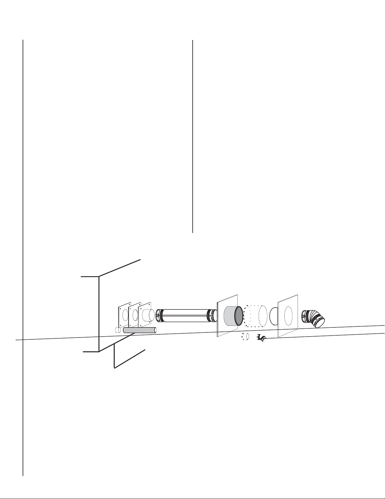
Listed Pellet Vent
Termination Cap
1 foot Section of PL
Vent (listed to UL 641
or ULC S609)
3” or 4” liner
(listed to UL 1777
or ULC S635)
Chase Cover
Figure 32 - Existing Chimney Termaination
Figure 31 - Horizontal Direct Vent
IMPORTANT NOTES:
A fl exible corrugated chimney liner has much greater resistance to
the fl ow of fl ue gases than does a rigid liner. For this reason we
recommend that a larger, 4” liner be used on vertical runs exceeding
Termination When
Connected to
Masonry Chimney
or Existing Class
A Chimney
NOTE: DIAGRAMS & ILLUSTRATIONS ARE NOT TO SCALE
15 feet or that rigid venting be used as illustrated on this page (see
Full Chimney Reline).
If a fl exible corrugated chimney liner is used, it must be fully extended
to eliminate any sagging and to improve the exhaust fl ow.
Do not block opening at front of insert (below door).
6”
Min.
1” Min.
(25 mm)
to Trim
Page 19

CARE AND OPERATION
Control Board Operation
Stove ON/OFF Button – This button will turn your
stove on or off while in Manual or Automatic
mode (see Page 20 for details). The green
ON/OFF light at the top of control board will
indicate the ON/OFF status.
Heat Select Button – The heat select button
has three selection settings, Low, Medium and
High. Pressing the button will scroll the red
indicator lights from Low to High. The button
controls the pellet feed and combustion airfl ow
simultaneously. The control board is preset
to provide the optimum ratio of fuel and air at
each setting. Settings can be changed at any
time but will only take affect after the start-up
cycle is complete. Each press of the Heat Select
Button will increase the heat output, and will
scroll to the lowest setting after reaching the
maximum setting.
Blower Select Button – The blower select
button operates the room air blower. This will
change the fl ow of hot air into the room. Three
choices are available Low, Medium, and High.
When the blower select button is pressed the
yellow indicator light will scroll to Low, Medium,
or High.
When running your stove on high (controlled
with the heat select button), the control board
will not allow you to select the low blower speed.
This is a safety precaution to protect against
overheating. Blower settings can be changed
at any time, but will only take affect after the
start-up cycle is complete.
Fault Mode – The control system automatically
monitors the fl ame using a photoeye. If the
appliance runs out of pellets the control board
automatically goes into a “fault” status. The
control board will initiate the shut down cycle
and safely shut down the appliance leaving it
in the “fault” mode. The ON/OFF indicator light
near the top of the control board will fl ash
rapidly when in this mode. After refi lling the
hopper with pellets, press the ON/OFF button.
If a thermostat is not being used the stove will
go into the start-up cycle. If a thermostat is
being used the stove will go into the start-up
cycle if the thermostat is in the demand mode.
If the thermostat is in the stand-by mode when
the fault is cleared, the stove will remain in the
stand-by mode until it closes again.
Note: If the fuel feed trim or combustion air
trim needs to be adjusted, contact an authorized
Lennox Hearth Products Technician to calibrate
internal software. It is recommended that the
damper be used to fi ne-tune your stove to your
particular fuel and installation confi guration (see
Damper Adjustment on Page 9 and Damper
Adjustment Guideline on Page 21).
Power LED
(fault when
fl ashing)
Heat LED
Blower
LED
Heat
Calib.
Proudly made in the USA
Stove
ON/OFF
Button
(& start
button)
Heat
Select
Button
(Heat
output
control)
Blower
Select
Button
Figure 33 - Control Board
Note: The control board has an internal memory
which recalls the last setting prior to loss of
power. Because we individually check each
stove prior to packaging, one of the two scenarios will appear when you fi rst plug in your
pellet appliance.
1). The Green LED at the top of the control
board will illuminate and the blowers will be
running. This is a standard cool down mode
and will last no longer than fi ve minutes. This
happens during testing when the stove is
turned off (which initiates cool down mode)
and then is unplugged.
2). The Green LED at the top will illuminate and
the red and yellow LED’s will illuminate on the
control board, indicating that the appliance is
in the run mode. This happens during testing
if the stove is unplugged without fi rst turning the control board off (the control board
remembers its last setting, which was the
run mode).
If your appliance follows what is described in
number 2, simply press the ON/OFF button once
to turn the appliance off, this will initiate the cool
down mode. The appliance can be restarted at
any time during the cool down mode by pressing
the ON/OFF button once.
Flame Detection Sequence of Events - This is
what happens after fl ame has been detected.
• Happens within the Start-up Time Delay
sequence.
• 0 to 1 minute no fuel feed.
• Flame settles.
• Bed of embers built.
• 1 minute mark: Fuel Feed rate 20% for 4
minutes 15 seconds (1 second on / 4 seconds
off).
• 2 minute mark: igniter turns OFF / room air
blower = panel setting.
• 5 minute 15 seconds mark: exhaust blower
= panel setting / LED indicator still active.
Start-up Time delay ends 14 minutes 15 seconds after pushing the start button!
Photoeye
P/N
Label
Location
Power
Select
Main
Harness
Fuse
Figure 34 - Control Board (backside)
NOTE: DIAGRAMS & ILLUSTRATIONS ARE NOT TO SCALE
19
Page 20

Fuel Delivery Rate
The heat select button manages the fuel delivery rate by controlling the
amount of time the auger motor will run as follows:
Feed
Rate
Setting
Low =
Med.=
High =
Note: Maximum hopper capacity is 55 lb.’s
Auger Motor
ON/OFF Time
(seconds)
1 on/5.40 off 1.5 Lb.’s hr. 13,000 BTU/hr 37
1 on/3.30 off 2.5 Lb.’s/hr. 21,000 BTU/hr 22
1 on/1.75 off 3.8 Lb.’s/hr. 32,000 BTU/hr 15
* Lb.’s
Per Hour
Fuel Delivery
Approximate
BTU Per Hour
Fuel Delivery
BurnTime
(hours)
Table 7 - Fuel Delivery Rate, Profi le® 20 FS-2
When fi rst starting your pellet appliance, it will be necessary to prime the
auger. To prime the auger you need to fi rst fi ll the hopper with pellets,
and press the ON/OFF button on the control board. Wait approximately
2-1/2 minutes and turn the control board OFF and then back ON again.
Wait an additional 2-1/2 minutes (if necessary) and continue this process
until fuel begins to fall into the UltraGrate™. Remember, different brand
fuels feed at different rates.
Once fuel starts to enter the UltraGrate™, turn the stove OFF and then back
ON. The auger should now be primed and the stove should deliver enough
fuel for proper ignition. It may be necessary to follow these procedures
in the event that the hopper runs completely out of fuel.
Manual Operation:
Feed
Rate
Setting
Low =
Med.=
High =
Note: Maximum hopper capacity is 70 lb.’s
Auger Motor
ON/OFF Time
(seconds)
1 on/4.50 off 1.7 Lb.’s/hr 14,000 BTU/hr 41
1 on/1.90 off 2.6 Lb.’s/hr. 22,000 BTU/hr 27
1 on/1.15 off 4.5 Lb.’s/hr 38,000 BTU/hr 16
* Lb.’s
Per Hour
Fuel Delivery
Approximate
BTU Per Hour
Fuel Delivery
BurnTime
(hours)
Table 8 - Fuel Delivery Rate, Profi le 30 FS-2
Feed
Rate
Setting
Low =
Med.=
High =
Note: Maximum hopper capacity is 50 lb.’s
Auger Motor
ON/OFF Time
(seconds)
1 on/4.50 off 1.7 Lb.’s/hr 14,000 BTU/hr 30
1 on/1.90 off 2.6 Lb.’s/hr. 22,000 BTU/hr 20
1 on/1.15 off 4.5 Lb.’s/hr 38,000 BTU/hr 11
* Lb.’s
Per Hour
Fuel Delivery
Approximate
BTU Per Hour
Fuel Delivery
BurnTime
(hours)
Table 9 - Fuel Delivery Rate, Profi le 30 INS-2
* Feed rates are approximations only. Actual feed rate will vary
depending on size, quality and length of fuel used and variations
in line voltage.
Estimated heat input based on fuel value of 8400 BTU per lb. of
fuel.
Your pellet stove can be operated in either the manual or automatic mode.
The manual mode is used when operating without a thermostat. The automatic mode is used when utilizing a wall thermostat. When utilizing the
thermostat capability the burn time can be extended dramatically depending on thermostat setting. Note: It is normal for some ash to build up on
the inner glass surface at the lower burn settings.
Initial Start-Up / Empty Hopper or Feed chute:
During an initial start-up, or in the case where the hopper has run out
of fuel, it will be necessary to prime the auger feed system. The control
board is set to deliver fuel for approximately 2-1/2 minutes during startup, which, with a fully primed auger, will provide the appropriate amount
of fuel for ignition.
Pressing the stove ON/OFF button initiates the start-up cycle. The green
ON/OFF light, near the top of the control board, will light up to indicate the
“on” status. The fan speeds and pellet feeds are fi xed during this time to
provide appropriate ignition. The Fastfi re™ igniter system will light the
pellets feeding to the UltraGrate™, after about 3 minutes. The start-up
cycle is in effect for approximately 2 minutes after fl ame is detected in
the UltraGrate™. A photoeye monitors the existence of fl ame. After the
start-up cycle your stove will be in the run mode. At this point the stove
will operate with the heat output (heat select button) and blower settings
(blower select button) selected. These settings can be selected either
during or after the start-up cycle. Pressing the stove ON/OFF button during
the run mode will initiate the shut down cycle. The ON/OFF indicator
light will turn off. The pellets will stop feeding and the blowers will run
at a fi xed speed for approximately 10 minutes. At this point your stove
is safely shut down and can ONLY be restarted by pressing the stove
ON/OFF button again.
Automatic Operation:
Your stove is capable of running in an automatic mode with the use of
a wall thermostat.
For the thermostat to control the operation of the stove, the “ON” status
must be active on the stove’s ON/OFF button. The thermostat will establish
either a demand mode or a stand-by mode. The thermostat should be
set for the desired room temperature. If the room temperature drops
below the level on the thermostat the stove will automatically begin the
start-up cycle, as explained above in the Manual Operation section. Once
the start-up cycle is completed the stove will operate in whatever heat and
blower setting you have selected. For best operation under thermostat
control, the Medium or High settings recommended. When the desired
room temperature is reached the stove will automatically go into the shut
down cycle. The pellet feed will stop and the blowers will continue for
a controlled time allowing safe shut down of your stove. All lights will
remain on when the thermostat is open. The heat and blower settings can
be changed at any time, but only take affect during the run mode. When
the temperature in the room drops to the level set at the thermostat, the
stove will again begin the start-up cycle and resume automatic operation
in the demand mode.
Note: If the stove ON/OFF button is pressed while the thermostat is in the
standby mode the stove will not restart until the thermostat closes.
20
NOTE: DIAGRAMS & ILLUSTRATIONS ARE NOT TO SCALE
Page 21

Lighting Procedure Without Igniter
Your pellet appliance can be lit manually without
using the automatic igniter by following the
procedure below. If your stove is set up to run
on a thermostat, the thermostat circuit needs
to be closed (as if permanently in the demand
mode). The thermostat wires should be removed
from the rear of the stove and replaced with the
jumper originally supplied with your appliance. If
a jumper is not available the thermostat should
be set to the highest setting. This will keep the
stove in the demand mode. If your automatic
ignition system should ever need troubleshooting, repair or replacement, please contact your
authorized Lennox Hearth Products dealer.
1. Press the ON/OFF button on the control
board.
2. Wait approximately 2-1/2 minutes while the
pellets prime the UltraGrate™ (the pellets will
stop feeding automatically).
3. Place a small amount of an approved (nonvolatile) fi re starter on top of the pellets in
the UltraGrate™, (see your authorized Lennox
Hearth Products dealer for appropriate fi re
starting products). DO NOT USE FLAM-
MABLE LIQUIDS TO START YOUR STOVE!
4. Light the “fi re starter” with a match and close
the door.
5. The photoeye will detect that a fl ame is
present and will begin feeding pellets in
approximately 2 minutes.
6. The control board will continue to go through
the normal start-up cycle and the fl ame
should be well established within 10 minutes
from the time the ON/OFF button was initially
pressed. Remember – you are now in manual
mode and heat settings should be selected
to the desired room heat level.
Turning Off Your Stove
Press the stove ON/OFF button to initiate the
shut down cycle. The pellets will stop feeding
and the blowers will continue to run on a timed
cycle. The stove will shut down safely upon
completion of the shut down cycle.
Damper Operation (All Models)
The damper assembly controls the amount of
combustion air that is delivered to the fi rebox.
With the damper adjusted all the way in, the
airfl ow will be at its minimum. As the damper
is moved outward, more air is delivered (see
Damper Location and Adjustment on Page
9).
It will be necessary to monitor the appearance of
the fl ame during the fi rst 4-8 bags of pellets. If
the fl ame is smoky red or orange with evidence
of soot at the top of the fl ame, the damper will
need to be adjusted to deliver more combustion
air (see Damper Location and Adjustment on
Page 9). If the fl ame is “short” at the higher
burn rates, or if the pellets are burning up in
the UltraGrate™ before new pellets are fed into
the fi re, the damper may need to be adjusted to
deliver less combustion air.
After the damper is adjusted, re-evaluate the
appearance of the fl ame. It may be necessary
to continue adjusting the damper in increments
until proper combustion is achieved (the fl ame
should become yellow and begin to “dance”).
Once the damper has been properly set (and if the
routine maintenance is performed as needed),
the damper should not require re-adjustment
unless you are changing from a premium grade
pellet to a standard or high ash pellet, in which
case the damper may need to be moved outward
to help prevent the accumulation of ash in the
UltraGrate™.
Damper Adjustment Guideline
Lack of Combustion Air: By opening the
damper, this will increase combustion air
delivery. Symptoms of insuffi cient combustion
air include; unburned fuel, lazy smoky or red /
orange fl ame, excessive ash or soot, excessive
buildup on glass.
Contributing factors:
• High Altitude – Lack of oxygen
• Restrictive Venting (elbows, horizontal runs,
cold external chimneys, etc.)
• Dirty / Poor Quality Fuel
• Lack of Maintenance
Note: Excessive amounts of fl y ash built-up in
the UltraGrate™, clinkers in the UltraGrate™
or leakage of air (if the grate is not properly
seated) will starve the fi re for air. See Routine
Maintenance, on Pages 22 to 28 for information
on cleaning requirements.
Excessive Combustion Air: By adjusting the
damper to a more closed position will reduce
the combustion air delivery. Symptoms of
excessive air include; fuel burns too quickly
(results in smoking or smoldering pellets),
white to yellow fl ame, etc. If the damper is
open too far, the burning pellets will lift off the
grate and fl y up into the air much like popping
corn does.
Contributing factor:
• Venting system providing excessive draft.
Correct Combustion Air / Proper Burn Characteristics:
When the damper is correctly set, the burning
pellets should move (wiggle) around slightly
and the fl ame should be bright yellow.
Automatic Safety Features
Power Outage:
During a power outage, the stove will shut
down safely. The stove will automatically restart
when power is resumed. The solid state control
board has an internal memory that will retain
heat output and blower speed settings through
voltage interruptions.
A small amount of smoke may leak from
the top of the window glass, the hopper and
from the combustion air intake, if the stove is
vented horizontally with no vertical pipe. This
will not persist for more than 3 to 5 minutes
and will not be safety hazard. It may set off
your smoke alarm.
Note: If the area in which you live is prone to
frequent power outages, it is recommended
that a minimum of 8 feet (2-1/2 meters) of
vertical vent pipe be included in a free-standing
installation to induce a natural draft in the event
of a power failure.
Overheating:
A high temperature thermal switch will automatically shut down the stove if it overheats.
Allow up to 45 minutes cooling time before
re-lighting. Keep enough convection air going
through stove to keep it cooling properly
(adjust room air blower speed to a higher
setting), this will ensure long life of the stove.
If the overheating continues, contact your
authorized Lennox Hearth Products dealer for
more information.
NOTE: DIAGRAMS & ILLUSTRATIONS ARE NOT TO SCALE
21
Page 22

FUEL
Pellet Fuel Hopper - It is recommended to
open the hopper lid by grasping it on the side
as shown in Figure 35.
Open Hopper Lid by Grasping the Side
BE VERY CAREFUL NOT TO TOUCH
OTHER HOT AREAS ON STOVE!
Figure 35 - Hopper Lid, Profi le 20 FS-2
Clinkering - Silica (or sand) in the fuel, along
with other impurities, can cause clinkering. A
clinker is a hard mass of silica formed in the
burning process. Clinkering is a function of the
fuel, (not the stove), but adversely affects the
performance of the stove by blocking off the
air passages in the grate. Even P.F.I. approved
pellet fuel may tend to clinker. A clinker can be
removed from the UltraGrate™ and placed in
the ash pan with the use of the grate scraper
/ ash pan tool furnished with your stove. See
Routine Maintenance (on Pages 22 to 28) for
more information on cleaning.
Ash - The frequency of removal of the ash
and maintenance performed on the stove is
directly proportional to the ash content of the
fuel and the operation duration of your pellet
stove. Low ash fuel may allow longer intervals
between cleaning, however, a stove burning
high ash fuel may need to be cleaned as often
as everyday.
PLEASE NOTE: Lennox Hearth Products has
no control over the manufacturing of pellet fuel
and will not be held responsible for poor stove
performance or any damage caused by poor
quality pellet fuels.
Fuel Feed Rates - Different brands of pellets
will feed at varying rates due to their size and
density (length and diameter). This may require
a slight adjustment in the damper control (see
Page 9) or the fuel feed trim to compensate
(see note at the top of Page 19).
Figure 36 - UltraGrate™
Fuel Specifi cations - Using the UltraGrate burn
system, this appliance has been designed to
burn wood residue pellets with up to 3% ash
content. Agricultural pellets (i.e. corn, alfalfa
etc.) are not permitted to be burned in these
appliances. Dirty fuel will adversely affect the
performance of the stove.
CAUTION: THE USE OF UNAPPROVED, DIRTY,
WET AND / OR HIGH SALT CONTENT FUEL
WILL VOID THE WARRANTY!
Wood pellets manufactured to the pellet fuels
institute (P.F.I.) certifi cation standard are available in two grades, Standard and Premium. The
primary difference between the two is the ash
content of the pellets.
The P.F.I. specifi cation for standard grade
and premium grade residential pellet fuel
is as follows:
• CHLORIDES (Salt): Less than 300 p.p.m.
• BULK DENSITY: 40 lb. / Cu. Feet minimum
• MOISTURE CONTENT: 8% maximum
• ASH CONTENT: < 3% maximum (standard
grade) < 1% maximum (premium grade)
• FINES: 0.5% maximum through a 1/8”
screen
• BTU CONTENT: Minimum 8200 BTU per
pound.
Pellet Feed / Pellet Size - The pellet feed
system is designed to handle a wide range of
pellet sizes up to a maximum of 5/16” diameter. Different pellets may feed at considerably
different rates. You may notice a difference in
the burn if you change pellet fuel sizes. The
longer the pellet, the slower it will feed and
vice versa. If the stove will not stay burning at
the minimum fuel feed setting, those particular
pellets may not be feeding fast enough. If this
happens, reduce the amount of combustion air
by adjusting the damper. See Page 9 before
adjusting the damper.
Long Burn Time - When operated correctly,
this appliance cannot be overfi red. Continuous
operation at a maximum burn can, however,
shorten the life of the electrical components
(blowers, motors, and electronic controls), and
is not recommended. Typical approved operation
would include running at the low to mid range
setting with occasional running on the maximum
setting during the coldest periods of the winter.
The blower speed control should be turned to
high when operating the stove on the high heat
setting. A lower heat setting is recommended
for overnight operation or when the room is
vacated for long periods of time.
Note: See Fuel Delivery Rate on Page 20 for
burn times.
ROUTINE MAINTENANCE
Cleaning
IMPORTANT
Unplug and Ensure Stove is Cold
Before Performing Any Maintenance Work.
The following areas need to be inspected and
cleaned during routine cleaning:
• Heat Exchange Tubes / Tube Scraper
• Baffl e Plates
• Window Wash
• Ash Clean-Out Ports
• UltraGrate (Burn Grate)
• Ash Slide Plate (free-standing models
only)
• Ash Pan
• Exhaust Passages / Vent Pipe and Creosote
Removal
• Gaskets
• Photoeye
• Paint Touch-up
• Cleaning Rear Stove Compartment
Heat Exchange Tubes (All Models)
Clean Heat Exchange Tubes Only When The
Appliance is Cool.
Tube Scraper
Using the hole in the handle of the Grate Scraper
Tool to “grab” onto the rod. Using the Grate
Scraper Tool, pull the rod up and out towards
the opening of the fi rebox. Continue pulling
until the Tube Scraper reaches the top of the
fi rebox. The rod is located on the outside,
above the door. Pull the tube scraper out, then
repeat 2–3 times to remove fl y ash from the
heat exchange tubes.
22
NOTE: DIAGRAMS & ILLUSTRATIONS ARE NOT TO SCALE
Page 23

(Model Profi le® 20 FS-2 only)
It may be easier to clean the tubes if the heat exchanger baffl e plate is
removed fi rst (located in the fi rebox below exchange tubes). To remove,
loosen the two screws holding the baffl e in place (do not fully remove).
The baffl e plate contains keyhole slots, which allows the screws to remain
in place while removing the baffl e plate. Remove the baffl e plate diagonally
through door opening. The tube scraper rod can now be pulled in a more
horizontal manner, which allows the scraper to move more freely.
Note: The baffl e plate should be removed at least once a year to allow
for a thorough cleaning.
WARNING
DO NOT USE BRUSH ON HOT STOVE!
With tube scraper rod pulled out 2 to 3 inches, insert brush behind tube
scraper and remove ash build-up. Clean to the left and right side of heat
exchanger, between tubes and the top of the fi rebox.
(Recommended Frequency
of 2 weeks - 2 months)
Figure 37 - Tube Scraper Rod
(Recommended Frequency
of 2 days – 2 weeks)
Figure 38 - Pulling Tube Scraper Rod
Cleaning Behind Tube Scraper (Profi le 30-2 Series Only)
Clean between the heat exchange tubes using a cleaning brush as illustrated in the picture below.
Figure 39 - Clean Behind Tube Scraper
Window Wash
Periodically remove the fi ve screws that secure the window wash bracket
to the door frame, using a 5/16” socket (the Profi le 30-2 Series has a
window wash bracket at the top and bottom of the door frame). Lift out
the window wash bracket, and set aside. Using a small brush, sweep out
all debris buildup from behind the window wash bracket. After all debris
has been removed re-attach the window wash bracket(s).
(Recommended
Frequency of 1 year)
Figure 40 - Remove Window Wash Bracket (5 screws)
NOTE: DIAGRAMS & ILLUSTRATIONS ARE NOT TO SCALE
23
Page 24

(Recommended
Frequency of 1 year)
Figure 41 - Sweep Away Debris from Behind Window Wash Bracket
Ash Clean-out Ports
IMPORTANT
• Ensure appliance is cold before beginning.
• Firebrick panels must be installed before operating unit.
®
• Model profi le
over each clean-out port. The covers must be
reinstalled before operating the unit.
• Ash clean-out ports must be cleaned out as part
of routine maintenance.
Accessing Ash Clean-Out Ports – Model: Profi le 20 FS-2
1) Open fi rebox door.
2) Remove Firebrick Panels:
a. Remove the two fi rebrick retainer brackets using a 5/16” nut
driver (located on the left and right side of the fi rebrick inside
fi rebox). Loosen the screws (do not remove) until screw heads
can be removed through the key hole slots in the brackets.
b. With the brick retainer brackets removed, lift fi rebrick panels up
and out.
3) Using an approved ash vacuum (a brush can also be used), remove
the ash build-up.
4) Reinstall fi rebrick panels.
5) Close fi rebox door.
30-2 series has a cover installed
Accessing Ash Clean-Out Ports – Model: Profi le 30 FS-2 and Profi le
30 INS-2
1) Open fi rebox door.
2) Using a 5/16” nut driver, loosen the screws on the two clean-out covers
(until screw heads will release through the key hole slots). Remove
covers.
3) Using an approved ash vacuum (a brush can also be used), remove
the ash build-up.
4) After cleaning, reinstall the clean-out covers and tighten screws.
5) Close fi rebox door.
Remove Covers And
(Minimum Frequency
of 1-2 months)
Vacuum Out Fly Ash
Figure 43 - Accessing Ash Clean-Out Ports – Profi le 30 Series
UltraGrate™ (Burn Grate for All Models)
Inspect the UltraGrate periodically so that the air holes don't clog with ash
or clinkers. The UltraGrate can easily be cleaned with the grate scraper
/ ash pan tool, or it can be removed for cleaning. It is very important to
monitor the ash build up under the UltraGrate, as too much of ash will
block combustion air from entering the grate, causing pellets to pile-up
in the grate. The ash build-up under the grate is easily dumped into the
ash pan by pulling out the ash slide weekly (see Ash Slide Plate, Figure
45). The grate cleaning procedure is the same for all models.
UltraGrate
24
(Recommended Frequency of 1-2 months)
(fi rebox viewed from front with
fi rebrick panels removed)
Vacuum Out Fly Ash
Clean-Out Ports (indicated by arrows)
Figure 42 - Ash Clean-Out Ports, Profi le 20 FS-2
NOTE: DIAGRAMS & ILLUSTRATIONS ARE NOT TO SCALE
(Recommended Frequency
of 1 day – 2 weeks)
Figure 44 - Inspect UltraGrate and Clean if Necessary
Page 25

Ash Slide Plate (Profi le® 20 FS-2 and Profi le 30 FS-2)
Ash Pan (Profi le 30 INS-2)
Ash that accumulates around the grate can be “dropped” into the ash
pan as follows:
1. Open the fi rebox door.
2. Using the grate scraper tool, pull open the ash release slide plate (see
Figure 45).
3. Using a brush, sweep the ashes from the fi rebox through openings to
the ash pan.
4. Close the ash slide plate, then close the fi rebox door.
IMPORTANT NOTE: Make sure to fully close the ash slide plate when
complete. Failure to close the ash release slide plate completely may
cause the fuel to burn poorly (due to reduced air fl ow through the grate),
which may then cause pellets to “pile up” in the grate. The ash slides
must be fully closed for the fi rebox door to close.
(Recommended Frequency
of 1 day – 2 weeks)
Ash Slide Plate
The Profi le 30 INS-2 has three ash pans (left side, right side and lower
center). The ash pans should be emptied whenever necessary. The ash
pans can be accessed by opening the fi rebox door. Remove the left and
right ash pans by lifting them out. The lower center ash pan can be removed
by pulling it straight out using the grate scraper tool (see Figure 47). Be
sure to dump ashes into a non-combustible container. All ash removal
and cleaning should be done while the stove is cold.
(Minimum Frequency
of 1 day – 1 week)
Figure 47 - Lower Ash Pan, Profi le 30 INS-2
Creosote Removal (All Models)
When wood is burned slowly, it produces tar and other organic vapors,
which combine with expelled moisture to form creosote. The creosote
vapors condense in the relatively cool chimney fl ue of a slow-burning
fi re. As a result, creosote residue accumulates on the fl ue lining.
Figure 45 - Using the Ash Slide Plate
Ash Pan (Profi le 20 FS-2 and Profi le 30 FS-2)
The ash pan will have to be emptied periodically, depending on amount
of fuel consumed. The ash pan is located in the pedestal on the Profi le
20-2 and Profi le 30 FS-2. It can be removed by turning the T-Bar latch
fully counterclockwise.
(Recommended Frequency
of 2 days – 2 weeks)
When ignited this creosote makes an extremely hot fi re. The chimney
connector and chimney should be inspected at least once every two
months during the heating season to determine if a creosote buildup
has occurred.
If creosote has accumulated it should be removed to reduce the risk of
a chimney fi re.
Exhaust Passages And Vent Pipe (All Models)
Inspect frequently and clean when necessary. Fly ash will accumulate at
all bends in the exhaust system.
Note: Large amounts of fl y ash build-up will create a lack of combustion
air. Removing the clean-out tee cap on vertical installations will allow an
inspection of the ash build-up in the clean-out tee and will help you to
decide how frequently more extensive cleaning must be performed.
Rain Cap
Clean-Out
Tee
Figure 46 - Ash Pan, Profi le 20 FS-2 and Profi le 30 FS-2
NOTE: DIAGRAMS & ILLUSTRATIONS ARE NOT TO SCALE
Figure 48 - Clean Vent Components
25
Page 26

Photoeye (All Models)
Clean-Out
Tee
Remove cover, then
remove ash
(Minimum Frequency
of 1-2 months)
Figure 49 - Remove Ash from Clean-Out Tee
Door Rope Gasket (All Models)
The condition of the rope gasket around the door and windows should be
checked periodically and replaced or repaired if necessary. A one-inch strip
of paper may be used to perform a test of the integrity of the door seal. Close
the door on the paper in at least eight points (see Figures 50 and 51). It is
normal to feel only a slight amount of friction. The door gasket does not need
to be “tight” in all areas, since a small amount of leakage is not hazardous
or detrimental to the performance of your stove.
ENSURE APPLIANCE IS COLD BEFORE BEGINNING
As a part of normal maintenance, buildup of pellet debris (fi nes) must be
periodically removed from the photoeye fi lter. This fi lter can be cleaned
by following either procedure (A) or (B) on this page:
Note: The photoeye views the fi re through a fi lter. The fi lter is located at
the top of the feed chute near the hopper (on the left side for Profi le
®
20 FS-2, and on the right side for models Profi le® 30 FS-2 and Profi le
30 INS-2). This area should be cleaned periodically to prevent excessive
build-up, which may cause the stove to go into “fault” mode.
(A) Cleaning Photoeye Filter Without Removing it:
1. Open the front door to access the feed chute.
2. Remove the buildup on the fi lter as explained in either “a” or “b” below
(note: it may help to use a mirror and a fl ashlight to view the fi lter as
shown in the following picture):
Feed Chute
Check seal at points
indicated
Figure 50 - Checking Door Seal
Important Note: Paper should
be no wider than a dollar bill.
(Recommended
Frequency of 1 year)
Mirror
Figure 52 - Use Mirror to View Filter
a. Using a long soft bristled brush (i.e. artists brush), extend it
deep into the feed chute and sweep away any pellet fi nes (left
side Profi le 20 FS-2, right side Profi le 30-2 Series).
b. Canned compressed air can also be used to remove pellet debris
from the photoeye fi lter (use only canned compressed air such
as what can be commonly purchased at a computer or offi ce
supply store and some drug stores). Read and follow the instructions on the spray can. Attach the tube (straw) to the nozzle on
the canned air (a tube is commonly provided with compressed
air. It is similar in use to the tube supplied with WD-40, Spray
Lubricant). Spray the canned air deep into the feed chute until
all “fi nes” are removed (direct it to the left side for model Profi le
20 FS-2, and to the right side for the Profi le 30-2 Series).
Note: The photoeye lens should be inspected annually and cleaned if
necessary as shown in method (B).
26
Figure 51 - Checking Door Seal
(Recommended
Frequency of 1 year)
NOTE: DIAGRAMS & ILLUSTRATIONS ARE NOT TO SCALE
Page 27

(B) Removing Photoeye Filter for Cleaning:
1. Lift off cover plate and turn over (the photoeye is attached to the inside
surface of cover). Wipe away any dust or debris from the photoeye
lens (see Figure 53).
CAUTION: If the fi lter is not reinstalled, refl ective light in the room may
result in a fault, thus shutting down of the unit.
Photoeye Access Inside Hopper
To access photoeye, open hopper and remove
the 3 nuts on cover plate (see picture below).
2. Clean Filter as follows: With the photoeye cover plate removed, look
inside the opening. You will see an amber colored square glass fi lter
secured in place by a bracket and 2 nuts. Using an 11/32” nut driver,
remove the 2 nuts and lift off the bracket. Using your fi nger slide fi lter
up and out.
3. Wipe away any dust or debris on fi lter, then reinstall fi lter, fi lter bracket
and cover plate with photoeye.
IMPORTANT: When reinstalling photoeye and cover, be careful not to
damage the wires. Pay special attention in positioning wires away
from photoeye (which could obstruct it from sensing light).
Using a 11/32” nut
driver remove the 3 nuts
to access photoeye and
fi lter.
Clean Photoeye Lens
Clean Photoeye Lens
Photoeye Cover
Plate
Opening Side Panels
®
Profi le
30 FS-2:
1) Using a 1/4” nut driver, remove the screw from underneath the side
panel at the front edge (see Figure 54).
2) Pull panel outward (on the upper portion of side panel) until the 2 ball
studs on the inside of the panel releases. Note: The side panel will
hinge open from the front.
3) After maintenance is complete, reinstall the retaining screw to
prevent the panel from being accidentally opened.
Remove side panel
retaining screw.
Remove Filter and Wipe Clean
Filter
(Minimum frequency of 4 weeks - 6 months)
Figure 53 - Clean Photoeye Lens and Filter
Figure 54 - Opening Side Panels, Profi le 30 FS-2
Profi le 20 FS-2:
1) Using a 1/4” nut driver remove the screw located at the front top of
the panel (see Figure 55).
2) Pull panel outward (on lower portion of side panel) until the ball stud
on the inside of the panel releases. Note: The side panel will hinge
open from the front.
3) After maintenance is complete, reinstall the retaining screw to
prevent the panel from being accidentally opened.
NOTE: DIAGRAMS & ILLUSTRATIONS ARE NOT TO SCALE
27
Page 28

Motor Lubrication
The blowers are permanently lubricated by the manufacturer. Do not apply
oil to any part of the blower, doing so may cause damage.
Remove side panel
retaining screw.
Figure 55 - Opening Side Panels, Profi le® 20 FS-2
Rear Stove Compartment (All Models)
The rear stove compartment should be cleaned periodically (a minimum
of once a year). DISCONNECT ELECTRICAL CORD PRIOR TO CLEANING
STOVE. Any household dust, pet hair or sawdust should be vacuumed
or wiped out of the rear compartment of the stove, room air blower, and
combustion blower (paying special attention to vacuuming out the intakes
of both blowers). The electrical components should be wiped clean.
Small Area Paint Touch-up
The stove body is painted with a quality high-temperature stove paint.
Use only model TSPK-B Stove Paint, Catalog # 70K99. Do not touch-up
your stove with any other paint.
Using one small piece of 320 grit sand paper and lightly sand the blemish so
that the edges are “feathered” or smooth to the touch between the painted
and bare surfaces. Do not let the sand paper gum up with paint, as this
will cause scratches on the metal surface. If there are any scratches, use
600 grit sandpaper instead. Mask off surfaces you do not want painted.
Paint lightly over the bare surface fi rst as this will act as an undercoat.
Then paint over a larger area in smooth even strokes to blend.
28
NOTE: DIAGRAMS & ILLUSTRATIONS ARE NOT TO SCALE
Page 29

SPECIFICATIONS - PROFILE® 20 FS-2
Cat. No. H0367 Model Profi le 20 FS-2 Pellet Stove
Flue Size 3” (76 mm Rear)
Width, Overall 22-3/8” (568 mm)
Depth, Overall 22-3/4” (578 mm)
Depth, Overall w / 3” tee 28-1/2” (724 mm)
Height 28-5/8” (727 mm)
Floor to Rear
Flue Center 11-1/4” (286 mm)
22-3/8"
28-5/8"
Facing back of unit,
outside edge of left side
to center of rear
fl ue outlet center 6-1/2” (165 mm)
Floor to Rear
Outside Air Inlet 12” (305 mm)
Facing back of Unit
outside edge of right side
to center of air inlet 8 3/8” (213 mm)
Floor Protection Front and Sides: 6” (152 mm)
Requirements Back: Up to 6” (152 mm)
Standard Features Fastfi re™ Self Igniter
Wall Thermostat
(wire included)
Hopper Capacity 55 lbs.
Burn time 15 - 37 hours
Fuse, Control Board 5 Amp, 250 volt, 3AG
Fuse, Igniter 6 Amp, 125 volt
Heat Input (BTU’s per hour) 13,000 - 32,000 BTU / hr
Overall Effi ciency 75 - 81%
11-1/4”
6-1/2"
BACK VIEW
28 1/2"
w/clean-out tee
22 3/4"
8-3/8"
12"
8-¾”
Emissions 0.4 gr / hr (varies w/size and
type of fuel) EPA exempt
Shipping Weight 215 lbs.
Room Air Blower 150 CFM; .8 Amps,
2175 rpm
Exhaust Blower 95 CFM: 1.0 Amps,
3000 rpm
Auger Motor 1.1 RPM; .4 Amps
Options Nickel or Gold Trim Kits
4” Quick Disconnect
Log Set
NOTE: DIAGRAMS & ILLUSTRATIONS ARE NOT TO SCALE
SIDE VIEW
Note: Dimensions shown are approximations only (+/- 1/4”)
Non-combustible fl oor protection is required (see Floor Protection,
Page 4). When installed at clearances less than 6”, the fl oor protector
is only required to extend to the wall.
Fuel delivery and burn times will vary depending on size and type of fuel
used. Estimated heat input based on fuel value of 8400 BTU per lb.
Fuses are rated as fast blow
29
Page 30

SPECIFICATIONS - PROFILE® 30 FS-2
Cat. No. H0368 Model Profi le 30 FS-2 Pellet Stove
Flue Size 3” (76 mm) Rear
25-7/8"
Width, Overall 25-7/8” (657 mm)
Depth, Overall 24-7/8” (632 mm)
Depth, Overall w / 3” tee 30-3/4” (781 mm)
Height 31-3/8” (797 mm)
Floor to Rear
Flue Center 16-7/8” (429 mm)
Facing Back of Unit,
outside edge on right
to center of rear
fl ue outlet 5-1/8” (129 mm)
Floor to Rear
Outside Air Inlet 10” (254 mm)
Facing Back of Unit
outside edge on left
to center of air inlet 13” (330 mm)
Floor Protection Front and Side: 6” (152 mm)
Requirements Back: 1” (25 mm)
Standard Features Fastfi re™ Self Igniter
Wall Thermostat
(wire included)
10"
8-7/8”
13”
31-3/8"
16-7/8"
5-1/8”
BACK VIEW
30-3/4"
24-7/8"
Hopper Capacity 70 bs.
Burn time 16 - 41 hours
Fuse, Control Board 5 Amp, 250 volt, 3AG
Fuse, Igniter 6 Amp, 125 volt
Heat Input (Max.) 14,000 - 38,000 BTU / hr
Overall Effi ciency 81%
Emissions 1.9 gr / hr (varies
w / size and type of fuel)
EPA exempt
Ship Weight 270 lbs.
Room Air Blower 150 CFM; .8 Amps,
2175 rpm
Exhaust Blower 95 CFM: 1.0 Amps,
3000 rpm
Auger Motor 1.1 RPM; .4 Amps
Options Nickel or Gold Trim Kits
4” Quick Disconnect
Log Set
Note: Dimensions shown are approximations only (+/- 1/4”)
Non-combustible fl oor protection must be used when installed on carpet
(see Floor Protection, Page 5).
Fuel delivery and burn times will vary depending on size and type of fuel
used. Estimated heat input based on fuel value of 8400 BTU per lb.
Fuses are rated as fast blow.
SIDE VIEW
30
NOTE: DIAGRAMS & ILLUSTRATIONS ARE NOT TO SCALE
Page 31

SPECIFICATIONS - PROFILE® 30 INS-2
Cat. No. H0369 Model Profi le 30 INS-2 Pellet Insert
Flue Size 3” (75 mm) Rear
Width, Overall front (w/o surround) 26” (660 mm)
Width, Overall back (w/o surround) 24-1/8” (613 mm)
Depth, Overall (w/o surround) 26-1/4” (667 mm)
Height, rear (w/o surround) 19-15/16” (506 mm)
Height, front (w/o surround) 23-5/8” (600 mm)
Floor to Rear
Flue Center 9-1/4” (235 mm)
Fireplace Face to Rear
Flue Outlet Center (3” tee) 13-1/4” (337 mm)
Dimensions into Fireplace
Minimum Height 20-1/8” (511 mm)
Minimum Width @ Front
(extends back 1 ½”) 32” (813 mm)
Minimum Width @ Back 24-5/8” (626 mm)
Minimum Depth 17-3/4” (451 mm)
Facing Back of Unit,
Right Outside Edge of Unit
to Center of Rear Flue Outlet 5” (127 mm)
Floor to Rear
Outside Air Inlet 2-1/8” (54 mm)
Facing Back of Unit,
Right Outside Edge of Unit
to Center of Air Inlet 12-7/16” (316 mm)
Control
Board
23-5/8”
Combustion
Air Inlet
32”
13”
12-1/2”
24-1/8”
BACK VIEW
26-1/4”
Damper
Arm
9-1/4”
5”
2-1/8”
19-7/8”
Floor Protection
Requirements Front: 6” (152 mm)
Standard Features Fastfi re™ Self Igniter
Wall Thermostat
(wire included)
Hopper Capacity 50 lbs.
Burn time 11 - 30 hours
Fuse, Control Board 5 Amp, 250 volt, 3AG
Fuse, Igniter 6 Amp, 125 volt
Heat Input (Max.) 14,000 - 38,000 BTU / hr
Overall Effi ciency 81%
Emissions 1.9 gr / hr (varies w/size and
type of fuel) EPA exempt
Ship Weight 230 lbs.
Room Air Blower 150 CFM; .8 Amps, 2175 rpm
Exhaust Blower 95 CFM: 1.0 Amps, 3000 rpm
Auger Motor 1.1 RPM; .4 Amps
Options Nickel or Gold Trim Kits
4” Quick Disconnect
Log Set
NOTE: DIAGRAMS & ILLUSTRATIONS ARE NOT TO SCALE
SIDE VIEW
Clean-Out
Tee
2-3/4”
Damper
Arm
Note: Dimensions shown are approximations only (+/- 1/4”)
Non-combustible fl oor protection must be used when installed on carpet
(see Hearth Protection, Page 7).
Fuel delivery and burn times will vary depending on size and type of fuel
used. Estimated heat input based on fuel value of 8400 BTU per lb.
Fuses are rated as fast blow
31-3/4”
5”
Control
25-3/4”
TOP VIEW
17-3/4”
Panel
31
Page 32

COMPONENT DEFINITIONS
Air Wash
To inhibit buildup of soot on the door glass, air
is delivered to the glass through an air wash
system located in the doorframe surrounding
the glass.
Auger
It transfers the fuel from the hopper to the feed
chute to deliver pellets to the UltraGrate™.
Auger Motor
Drives the Auger. Motor specifi cations are: .4
Amp, 1.1 RPM (revolutions per minute).
Blower, Room Air (Convection)
The blower function is to transfer the heat from
the appliance to heat the room air.
Blower, Exhaust (Draft Inducer/combustion)
It has a radial impeller to deliver more air to the
UltraGrate™. It pulls air into the UltraGrateby
creating a negative pressure. This is done by
extracting the exhaust gases out of the fi rebox
and pushing the exhaust downstream to the
fl ue exit.
Thermal Switch, High Limit (L250-30F, N/C)
There are 2 of these thermal switches on this
model. If a temperature reaches 250° F., the
high limit auto reset will “trip” and stop the fl ow
of electricity to the auger motor. The thermal
switches will not automatically reset until it has
cooled below 220° F).
Thermal Switch for Room Air Blower – This
thermal switch is located on the room air
blower jacket and is designed to detect an
overfi re condition.
Thermal Switch for Combustion Air Inlet
– This thermal switch is located on the
combustion air inlet and is designed to
detect reversed fl ow. If negative pressure
in the dwelling (i.e. An extremely tight house
which may not supply adequate combustion
and ventilation air) causes the exhaust to
pull back from the combustion air inlet, the
heat from the exhaust will result in heat
activation of this thermal switch.
Door Switch
®
(Profi le
30 FS-2 and Profi le 30 INS-2)
If the door is opened during operation (on model
Profi le 30 FS-2 and Profi le 30 INS-2), this switch
disconnects power to the auger motor resulting
in the unit shutting down.
Heat Select Button
This is the heat output control button. It controls
power to the feed system - auger motor and
exhaust blower. Use the heat select button to
adjust to any of the three feed rate settings
(which controls the burn rate).
Photoeye
The photoelectric eye that senses the fl ame, or
lack of. It is designed to signal the control board
to discontinue power to the auger motor if it
fl ame is not sensed in the UltraGrate.
Pressure Switch
A safety device used to shut off the feed system
(auger motor) if there is too much back pressure in venting system. Some possible causes
are as follows:
• The venting system is obstructed.
• High altitude or other misc. environmental
conditions affecting exhaust fl ow.
• Improper venting system.
UltraGrate (Burn Grate)
This is where combustion occurs and may be
referred to as the “Burn Grate”.
POWER
DISCONNECT
NEUTRAL
GROUND
POWER (HOT)
Thermostat
Connector
JUMPER
(white)
(black)
(purple)
(purple)
6 AMP
120V.
Hopper
The hopper is where the pellets are stored.
(INLET) HIGH LIMIT SWITCH
L250-30F(N/C)
(brown)
16 8
(brown)
(black)
(blue)
(orange)
91
(red)
(red)
(black)
IGNITER
PRESSURE SWITCH
HIGH LIMIT SWITCH
L250-30F(N/C)
Exhaust
(combustion)
Blower
N/C
Convection
Room Air
Blower
Auger
Motor
21
43
NOTE: Switch conditions given at
room temperature, Stove OFF
N/C = Normally Closed
(yellow)
Photoeye
(yellow)
JUMPER 1-3
JUMPER 2-4
32
Figure 56 - WIRING DIAGRAM 120 V AC
* N/C = Normally Closed Switch
N/O = Normally Open Switch
NOTE: DIAGRAMS & ILLUSTRATIONS ARE NOT TO SCALE
Page 33

TROUBLESHOOTING
QUALIFIED TECHNICIANS ONLY
Unplug Appliance Before Performing Any Troubleshooting or Maintenance
PROBLEM CAUSE(S) SOLUTIONS
Fire burns with a lazy orange fl ame. Pellets build up
1.
in the grate and there is excessive glass soot that is diffi cult to remove (Ash and soot are a product of combustion
with any wood products, so some build-up on the glass
is normal).
2. Fire goes out or stove shuts down automatically A) Stove has run out of fuel.
3. Pellets will not feed. A) The hopper is empty.
A) There is insuffi cient combustion air. A
B) Pellets are not feeding.
C) The high limit temperature switch has tripped.
D) There is too much combustion air for the amount
of fuel.
B) The auger motor or control board may be defec-
tive. The pressure switch tap or hose may be
blocked.
C) Back pressure in venting tripping pressure
switch.
) Lack of maintenance (clean UltraGrate™,
1
clean-out ports, exhaust fl ow passages, venting
system, exhaust blower intake, etc.
• Remove any clinkers or ash from the bottom of the
UltraGrate that might be obstructing the primary
air holes.
• Check that the heat exchange tubes are not coated
with ash.
• Clean internal exhaust ducts.
• Check gasket seal around the door. Use a thin
strip of paper, 1 in. wide. Open the door and close
it on the paper strip. A slight friction should be
felt when the paper strip is pulled. Repeat this
process at various locations around the door
gasket. Replace the door gasket if necessary.
• Check for blockage in the air inlet tube or exhaust
pipe. Clean as Necessary.
• Inspect glass seal to ensure that it is in good
condition and is properly seated to the door.
A2) Fuel trim may need to be adjusted down for
faster feeding fuels.
A3) Change to a better grade of fuel if necessary.
Check that the damper has been opened enough
for the amount of fuel fed.
A4) Have Your Authorized Lennox Hearth Products
dealer check your exhaust blower for proper
operation.
A5) The venting system design is too restrictive
(call your authorized Lennox Hearth Products
Technician to evaluate how the installation can be
corrected to satisfy the exhaust fl ow requirements
of the appliance).
A) Refi ll hopper.
B) See (Pellets will not feed) this Page.
C) Allow the appliance to cool for 1 hour, then re-light. If
the stove has been operating at a medium to high burn
rate with the room air blower adjusted to low, there
may not be enough air fl ow to dissipate the heat. On
higher feed rates, adjust the blower speed to a higher
setting. If this problem persists (particularly at lower burn
rates) then the high limit thermal switch may need to be
replaced by your authorized dealer.
D) Adjust the damper to reduce combustion air fl ow.
A). Refi ll hopper.
B).Check to be sure that there is no blockage in the pres-
sure tap or hose. Have your authorized Lennox Hearth
Products dealer diagnose the problem and clean or
replace any necessary parts.
C). If new installation check for excessive 90˚ bends,
long horizontal runs or excessive vertical run of 3” pipe.
Possibly change to 4” pipe. If older installation check for
excessive ash accumulation in pipe or other obstructions.
Clean out pipe.
D) Thermostat is in stand-by mode.
E) Thermostat wires disconnected.
F) High limit thermal switch may have been
tripped.
G) Door switch not engaged, stopping pellet feed
(Profi le® 30 FS-2 and Profi le 30 INS-2).
H) Self-aligning bearings in auger motor may be
misaligned.
D). Check to see if thermostat is set to low or if sun is
shining directly on thermostat.
E). Reinstall wires.
F). Allow stove to cool. Increase room air blower setting.
G). Have dealer check operation to determine if adjustment or replacement is necessary.
H). Gently tap the auger motor.
33
Page 34

TROUBLESHOOTING
QUALIFIED TECHNICIANS ONLY
Unplug Appliance Before Performing Any Troubleshooting or Maintenance
PROBLEM CAUSE(S) SOLUTIONS
4. Blowers will not operate when the ON/OFF start button
is depressed.
A) There is no power to the stove.
A) Check that the stove is plugged in to the wall
outlet.
B) There is no power to the control board.
5. There is soot or fl y ash in the house. A) The window is being cleaned when the stove is
operating.
B) There is leakage at the joints between the exhaust
blower, connection or exhaust pipe connections.
This will be evidenced by dust on the impeller of
the room air blower, and in the heat exchanger
area.
C) The vacuum cleaner is leaking.
6. Stove acts as if a fi re is present when there is not a fi re
in the grate.
A) Excessive sun light may be shining directly into
fi rebox from window.
7. Stove will not light. A) The igniter element may have failed.
B) There is not enough pellets in the UltraGrate.
8. Fault A) Photoeye not detecting fl ame.
B
) Check if the house circuit breaker has tripped.
1
B2) Check the wire connections on the high limit
thermal switch and control board.
A) Turn down the room air blower or turn off stove before
cleaning to prevent dispersion of ash and soot into the
room.
B) Seal up any leaks in the exhaust system with room
temperature vulcanizing high temperature silicone sealer
(RTV).
C) DO NOT use a standard household vacuum or “shop
vac” as the fi lters will leak the fi ne particles of ash. Clean
the stove with an approved ash vacuum ONLY.
A) Block excessive sunlight. Call authorized Lennox
Hearth Products dealer if problem persists.
A) Check igniter element fuse in rear stove compartment.
Call your authorized Lennox Hearth Products dealer. See
Lighting Procedure Without Igniter, Page 21.
B) Prime the feed system (see Initial Start-Up, Page 20).
A) Check connection at control board following yellow
wires to all connectors. Inspect and clean photoeye fi lter,
if necessary.
B) Stove has run out of fuel.
C) A disk has tripped / pressure switch.
D) Door switch not engaged, stopping pellet feed
®
(Profi le
30 FS-2 and Profi le 30 INS-2).
9. Blowers run continuously A) Wir e harness and/or control board has been damaged – unplug stove and contact dealer.
10. All lights on control are on but nothing happens A) When using a thermostat. Thermostat not calling for heat.
B) If not using a thermostat - Check thermostat
jumper
B) Refi ll hopper.
C) Blower intake, exhaust passages and / or venting
system needs cleaning (follow routine and annual
maintenance procedures).
D1) Have dealer check operation to determine if adjustment or replacement is necessary.
D2) If this does not correct the problem contact your local
authorized Lennox Hearth Products dealer.
A) Contact your local authorized Lennox Hearth Products
dealer.
A) The lights on the control board remain on even when
the thermostat is not demanding heat. When the thermostat demands heat the stove will begin to operate.
B) Ensure that the thermostat jumper at terminal block is
installed and making good contact.
34
NOTE: DIAGRAMS & ILLUSTRATIONS ARE NOT TO SCALE
Page 35

REPLACEMENT PARTS LIST
DOOR PARTS AND BODY COMPONENTS
Item Part No. / Cat. No. Description Stove Model
13640075 Clip Kit, Glass Bottom Profi le® 20 FS-2
13640086 Clip Kit, Glass Right and Left Side Profi le 20 FS-2
14750264 Clip Kit, Glass Top Bottom (Doors w/ 3pc glass) Profi le 30 FS-2 & INS-2
13640085 Clip Kit, Glass Top Profi le 20 FS-2
1 H3752 Door Assembly, Firebox (with 3 Piece Glass) Profi le 20 FS-2
2 H0297 Door Assembly, Firebox, DK-P30 (with 3 Piece Glass) Profi le 30 FS-2 & INS-2
26M81 Gasket, Door, 3/4” Rope, (8 Feet) Profi le 20 FS-2
61051000 Gasket, Door, 1” Rope, (7 Feet) Profi le 30 FS-2 & Profi le 30 INS-2
61057202 Gasket Kit, Glass (10 Feet) All
H0257 • Glass, Center Profi le 20 FS-2
H0258 • Glass, Side (order 2 if set is needed) Profi le 20 FS-2
H0254 • Glass, Center Profi le 30 FS-2 & Profi le 30 INS-2
H0255 • Glass, Side (order 2 if set is needed) Profi le 30 FS-2 & Profi le 30 INS-2
3 17250095 Handle Assembly, Door Profi le 20 FS-2
4 17150095 Handle Assembly, Door Profi le 30 FS-2 & Profi le 30 INS-2
5 14650047 Hinge Bracket, Door Profi le 20 FS-2
6 14750021 Hinge Bracket, Door Profi le 30 FS-2 & Profi le 30 INS-2
13740005 Bracket, Hopper Lid Support Profi le 30 FS-2
11950068 Bracket, Hopper Lid Support Profi le 20 FS-2
7 14650003 Panel, Left Side Profi le 20 FS-2
8 14650004 Panel, Right Side Profi le 20 FS-2
9 14750070 Panel, Left Side Profi le 30 FS-2
10 14750075 Panel, Right Side Profi le 30 FS-2
11 14650048 Panel, Rear Profi le 20 FS-2
12 14750150 Panel, Rear (2 piece) Profi le 30 FS-2
13 14750340 Panel, Left Side Profi le 30 INS-2
14 14750345 Panel, Right Side Profi le 30 INS-2
15 14750300 Panel, Top Profi le 30 INS-2
16 14650012 Panel, Top Profi le 20 FS-2
16 14750060 Panel, Top Profi le 30 FS-2
17 14750186 Pedestal Assembly Profi le 30 FS-2
14655000 Pedestal Assembly Profi le 20 FS-2
12051409 Knob, Control Panel Door (6 per package w/studs) All
•· Includes gasket.
ELECTRICAL PARTS
Item Part No. / Cat. No. Description Stove Model
18 12046300 Auger Motor All
43 12050011 Blower, Exhaust (complete) All
12056011 Blower Motor Only, Exhaust All
44 12146109 * Blower, Room Air, Hard Washer All
19 16053941 Control Board Profi le 20 FS-2
19 16052112 Control Board Profi le 30 FS-2 & Profi le 30 INS-2
20 12147705 Thermal Switch, High Limit, 250 DG (L250-30F,60T21)
Set of 3
All
35
Page 36

REPLACEMENT PARTS LIST
ELECTRICAL PARTS
Item Part No. / Cat. No. Description Stove Model
18150150 Fuse, Control Board, 5 Amp, 250 volt, Fast blow, 12pk. All
21 12150213 Igniter Assembly, Replacement, 380 Watts, 3.3 Amp.’s, 1 each(includes fuse holder
w/fuse)
22 14750404 Photoeye Kit, Replacement All
24 12058820 Power Cord, 8 feet All
26 16050001 Pressure Switch All
28 13050002 Switch, Door (3 per pkg.) Profi le
25 16050205 Thermostat, Wall, Honeywell (Thermostat Wire, P/N H3457, is not included) All
27 12050815 Wiring Harness All
H3457 Wire, Thermostat, 20’ coil - 18 gage (16020204) All
All
®
30 FS-2 & INS-2
FIREBOX PARTS
Item Part No. / Cat. No. Description Stove Model
13650046 Baffl e, Heat Exchange Profi le® 20 FS-2
29 13640028 Clips, Brick Profi le 20 FS-2
30 11750011 Clips, Brick Profi le 30 FS-2 & INS-2
31 14650011 Firebrick Set Profi le 20 FS-2
32 14750015 Firebrick Set Profi le 30 FS-2 & INS-2
33 12051263 UltraGrate All
36
AUGER SYSTEM COMPONENTS
Item Part No. / Cat. No. Description Stove Model
37 11756300 Auger Shaft Kit All
35 12041300 Collar and Screw Set, Auger (3 per pkg.) All
36 17250241 End Plate, Auger (fl ange) (w/nylatron bushing) All
MISC.
Item Part No. / Cat. No. Description Stove Model
14750306 Ashpan, Center, Left and Right, Profi le 30 INS-2 Profi le 30 INS-2
14751189 Ashpan, Profi le 30 FS-2 Profi le 30 FS-2
38 12050004 Brush, Cleaning (for exchange tubes) Profi le 30 FS-2 & INS-2
12021101 Bushing, Nylatron 1/2” All
12151306 Damper Rod Kit (includes 1/4” rod, handle and set collar) Profi le 20 FS-2 & Profi le 30 FS-2
39 61050003 Gasket, Auger Flange, 5 per pkg.. All
40 61050005 Gasket, Exhaust Blower, Fan Mount, 5 per pkg. All
41 61057203 Gasket, Room Air Blower, 5 per pkg. All
61050041 Gasket, Exhaust Blower, Tear Down, 5 per pkg. All
42 61050016 Gasket, Quick Disconnect, 5 per pkg.. All
13656003 Hose, Pressure Switch, 19” (may need to be cut to size) - 3 per pkg. All
17100034 Plate, Ash Clean-Out, Left Profi le 30 FS-2 & INS-2
17100035 Plate, Ash Clean-Out, Right Profi le 30 FS-2 & INS-2
14750014 Scraper Rod Kit, Replacement (Fits - Profi le Series, Free-Standing and Insert) All
14650015 Trim Kit, Standard, Met. Black, Replacement (louvers) Profi le 20 FS-2
14750055 Trim Kit, Standard, Met. Black, Replacement (louvers) Profi le 30 FS-2 & INS-2
45 12055500 Tool, Grate Scraper All
46 12050093 Quick Disconnect 3” Vent Side All
Page 37

REPLACEMENT PARTS DIAGRAMS
1
5
9
6
10
2
7
11
3
8
12
4
NOTE: DIAGRAMS & ILLUSTRATIONS ARE NOT TO SCALE
37
Page 38

REPLACEMENT PARTS DIAGRAMS
13
14
17
18
21
22
15
16
19
20
24
25
38
NOTE: DIAGRAMS & ILLUSTRATIONS ARE NOT TO SCALE
Page 39

REPLACEMENT PARTS DIAGRAMS
26
27
28
32
31
36
37
38
29
30
33
35
NOTE: DIAGRAMS & ILLUSTRATIONS ARE NOT TO SCALE
39
39
Page 40

REPLACEMENT PARTS DIAGRAMS
40
41
42
43
44
45
46
3”
40
NOTE: DIAGRAMS & ILLUSTRATIONS ARE NOT TO SCALE
Page 41

OPTIONAL ACCESSORIES
Item # Part # Model Description Stove Model
1 14 m46 TKP2-G Trim Kit, Gold Profi le
1 14 m47 TKP2-N Trim Kit, Nickel Profi le 20 FS-2
1 14 m49 TKP3-G Trim Kit, Gold Profi le 30 FS-2 & INS-2
1 14 m50 TKP3-N Trim Kit, Nickel Profi le 30 FS-2 & INS-2
2 14 m81 QDPC-4 Quick Disconnect Pipe Connector, 4” * All
70K99 TSPK-B Touch-up Spray Paint Kit, Black All
3 14 m52 SKSP3 Surround Kit, Small, 28-1/2” x 40-3/4”, Black Profi le 30 INS-2
3 14 m53 SKMP3 Surround Kit, Medium, 32” x 44”, Black Profi le 30 INS-2
3 14 m54 SKLP3 Surround Kit, Large, 36 x 48”, Black Profi le 30 INS-2
4 14 m55 STKSP3-B Surround Trim Kit, Small, 28-1/2” x 40-3/4”, Brass Profi le 30 INS-2
4 14 m56 STKMP3-B Surround Trim Kit, Medium, 32” x 44”, Brass Profi le 30 INS-2
4 14 m57 STKLP3-B Surround Trim Kit, Large, 36 x 48”, Brass Profi le 30 INS-2
5 H0244 DLS-P20 Decorative Log Set Profi le 20 FS-2
6 H0464 DLS-AO3 Decorative Log Set Profi le 30 FS-2 & INS-2
H0416 ZCK-PI Zero Clearance Kit (for installing insert as a built-in) Profi le 30 INS-2
70K99 TSPK – B Touch-up Spray Paint Kit, Black All
®
20 FS-2
1
Profile 30 FS-2 & Profile INS-2
Trim
Profile 20 FS-2
Trim
Converts from standard 3”
2
outlet to 4”
5
6
3
4
4”
Surround / Trim Sizes
Large:
36” (91.4cm) height
48” 121.9cm) width
Medium:
32” (81.3cm) height
44” (111.75cm) width
NOTE: DIAGRAMS & ILLUSTRATIONS ARE NOT TO SCALE
Small:
28 ½” (72.4cm) height
40 ¾” (103.5cm) width
41
Page 42

CERTIFIED FOR U.S. AND CANADA. LISTED ROOM
HEATER FOR USE WITH APFI/FFI APPROVED
PELLETIZED WOOD FUEL ONLY. FOR USE IN
MANUFACTURED (MOBILE) HOMES, AND AS AN
INSERT FOR MASONRY AND FACTORY BUILT
TO ASTM E-1509 / UL 1482 / ULC-S627 /ULC-S628 REPORT NO. 6658
(JULY 1993).
INSTALL AND USE ONLY IN ACCORDANCE WITH THE MANUFACTURER’S INSTALLATION INSTRUCTIONS. CONTACT LOCAL BUILDING
OR FIRE OFFICIALS ABOUT RESTRICTIONS AND INSTALLATION INSPECTION IN YOUR AREA. DO NOT CONNECT THIS UNIT TO A CHIMNEY FLUE SERVING ANOTHER APPLIANCE. SEE LOCAL BUILDING
CODE AND MANUFACTURER’S INSTRUCTIONS FOR PRECAUTIONS
REQUIRED FOR PASSING A CHIMNEY THROUGH A COMBUSTIBLE
WALL OR CEILING. THIS PELLET FIRED APPLIANCE HAS BEEN
TESTED AND LISTED FOR USE IN MANUFACTURED HOMES IN ACCORDANCE WITH OREGON ADMINISTRATIVE RULES 814-23-900
THROUGH 814-23-909.
OPERATE ONLY WITH FIREBRICK IN PLACE. WARNING: OPERATE
ONLY WITH VIEWING DOOR CLOSED. INSPECT FLUE FREQUENTLY
TO PREVENT ACCUMULATION OF SOOT. THE HEATER AND FLUE
MUST BE IN GOOD CONDITION. KEEP FURNISHINGS AND OTHER COMBUSTIBLE MATERIALS WELL AWAY FROM HEATER.
FIREPLACES. MODEL: PROFILE 20-2 TESTED
ROUTINE MAINTENANCE REMINDER
FREQUENCY OF CLEANING AND MAINTENANCE OF YOUR STOVE
DEPENDS ON THE ASH CONTENT OF THE PELLETS YOU BURN.
CHECK THE FOLLOWING PARTS OF YOUR STOVE WEEKLY FOR THE
FIRST MONTH TO DETERMINE THE FREQUENCY OF CLEANING.
SEE YOUR MANUAL AND/OR DEALER FOR MORE INFORMATION.
A. BURN GRATE
B. HEAT EXCHANGER TUBES
C. ASH PAN AND EXHAUST PIPE
INPUT RATING RANGE: 1.5 TO 3.8 LBS./HOUR (NOMINAL)
ELECTRICAL RATING: 60 HZ, 115 V, LESS THAN 10 AMP
DO NOT REMOVE THIS LABEL
WH-
MINIMUM CLEARANCES TO
COMBUSTIBLE MATERIALS
MANUFACTURED (MOBILE) HOME
FREESTANDING STOVE
INSTALLATION
SIDEWALL TO UNIT *A* 4”/102 MM 4”/102 MM
BACKWALL TO UNIT B 1”/26 MM 9”/229 MM
WALL TO UNIT CORNER C 1”/26 MM 1”/26 MM
ALCOVE TO FUEL HOPPER D 4”/102 MM 4”/102 MM
MAX. DEPTH OF ALCOVE E 24”/610 MM 24”/610 MM
FLUE TO WALL
FRONT/REAR/SIDE TO FLOOR
PROTECTION OUTSIDE EDGE I 6”/153MM 6”/153 MM
BACK WALL
F
B
A
JD
ECA
N
W T
LA
L
C
F
C
OR RESIDENTIAL INSTALLATION
HORIZONTAL FLUE-
DIRECTLY THROUGH WALL
INSTALLATION
F 3”/77 MM 3”/77 MM
ALCOVE BACK WALL
E
A
D
VERTICAL FLUE
INSTALLATION
B
INTERIOR
*60020146 REV E*
CAUTION:
SURFACES WHILE IN
OPERATION. DO NOT
TOUCH. CONTACT MAY
CAUSE SKIN BURNS.
KEEP CHILDREN, COMBUSTIBLE MATERIAL AND FURNISHINGS A CONSIDERABLE DISTANCE AWAY. SEE
NAMEPLACE AND INSTRUCTIONS.
TYPE OF FUEL: PELLETIZED WOOD
FUEL ONLY.
COMBUSTIBLE FLOOR MUST BE PROTECTED BY NON-COMBUSTIBLE MATERIAL EXTENDING BENEATH THE HEATER AND 6” TO
THE FRONT, SIDES AND REAR AS INDICATED OR TO THE NEAREST
PERMITTED COMBUSTIBLE MATERIAL.
USE 3” / 75mm or 4” / 100mm Type “PL” LISTED PELLET VENT AND
COMPLETE COMPONENTS.
D
MAY BE INSTALLED IN A MASONRY FIREPLACE THAT MEETS
NATIONAL AND LOCAL BUILDING CODE REQUIREMENTS (UBC
37 OR ULC S628). DO NOT REMOVE BRICKS OR MORTAR. MAY
BE INSTALLED IN A FACTORY BUILT (“ZERO CLEARANCE”)
FIREPLACE (UL 127 OR ULC S610). DO NOT ALTER OR MODIFY
THE FIREPLACE STRUCTURE. REFER TO OWNER’S MANUAL
FOR SPECIFIC INSTALLATION REQUIREMENTS.
INSERT MODEL
HOT
42
NOTE: DIAGRAMS & ILLUSTRATIONS ARE NOT TO SCALE
Page 43

MINIMUM CLEARANCES TO COMBUSTIBLE MATERIALS
INSTALLED AS
INSTALL AND USE ONLY IN ACCORDANCE WITH THE MANUFACTURER’S INSTALLATION
INSTRUCTIONS. CONTACT LOCAL BUILDING OR FIRE OFFICIALS ABOUT RESTRICTIONS AND
INSTALLATION INSPECTION IN YOUR AREA. DO NOT CONNECT THIS UNIT TO A CHIMNEY FLUE
SERVING ANOTHER FIREPLACE. SEE LOCAL BUILDING CODE AND MANUFACTURER’S
INSTRUCTIONS FOR PRECAUTIONS REQUIRED FOR PASSING A CHIMNEY THROUGH A COMBUSTIBLE WALL OR CEILING. THIS PELLET FIRED APPLIANCE HAS BEEN TESTED AND LISTED
FOR USE IN MANUFACTURED (MOBILE) HOMES IN ACCORDANCE WITH OREGON
ADMINISTRATIVE RULES 814-23-900 THROUGH 814-23-9O9.
OPERATE ONLY WITH FIREBRICKS IN PLACE. OPERATE ONLY WITH VIEWING DOOR AND ASH
REMOVAL DOOR CLOSED. INSPECT FLUE FREQUENTLY. CLEAN HEAT EXCHANGER AND FLUE
FREQUENTLY TO PREVENT ACCUMULATION OF SOOT. THE HEATER AND FLUE MUST BE IN
GOOD CONDITION. REQUIRED COMPONENTS: DAMPER SEALING PLATE FOR INSERT INSTALLATIONS. USE 3”/75MM OR 4”/100MM MODEL PL CHIMNEY COMPONENTS. KEEP FURNISHINGS AND OTHER COMBUSTIBLE MATERIALS WELL AWAY FROM HEATER.
ELECTRICAL RATING: 115V 60Hz Less than 10 Amp
FUEL INPUT RATING: 4.5 Lbs./Hr. Max.
FREESTANDING STOVE
SIDEWALL TO UNIT A* 6”/153 MM 6”/153 MM
BACKWALL TO UNIT B 1”/26 MM 9”/229 MM
CORNER TO UNIT C 1”/26 MM 1”/26 MM
ALCOVE TO FUEL HOPPER D 6”/153 MM 6”/153 MM
DEPTH OF ALCOVE E 16”/407 MM N/A
FLUE TO WALL F 3”/77MM 3”/77 MM
F
ROUTINE MAINTENANCE REMINDER
FREQUENCY OF CLEANING AND MAINTENANCE OF YOUR STOVE
DEPENDS ON THE ASH CONTENT OF THE PELLETS YOU BURN.
CHECK THE FOLLOWING PARTS OF YOUR STOVE WEEKLY FOR THE
FIRST MONTH TO DETERMINE CLEANING:
A. BURN GRATE
B. HEAT EXCHANGER TUBES
C. ASH TRAPS AND ASH PAN
G. SIDE WALL 6”/153 MM
H. SIDE TRIM 1”/26 MM
I. TOP TRIM 1”/26 MM
J. ADJACENT
18”/458 MM
WALL
SEE YOUR MANUAL AND/ DEALER FOR MORE INFORMATION.
MANUFACTURED (MOBILE) HOME OR RESIDENTIAL INSTALLATION
HORIZONTAL FLUE-DIRECTLY THROUGH WALL
INSTALLATION
INTERIOR VERTICAL FLUE
INSTALLATION
NOTE: DIAGRAMS & ILLUSTRATIONS ARE NOT TO SCALE
43
Page 44

INSTALLATION TIPS
CASCADE
T300P-2 SERIES
P/N 60020242, REV. NC
(Straight Up)
ADVANTAGE II-T C
ADVANTAGE OPTIMA & PROFILE SERIES
Pellet
Stove
Models:
Select Your Installation Type
Vertical Installation
BEST INSTALLATION:
BETTER INSTALLATION:
Vertical & Horizontal Installation
negative effects from wind
Natural draft improves operation and
(Up and Out)
Some natural draft aids venting.
Wind pressures may still affect operation
in location facing direct sunlight (not applicable to Advantage II-T C & Cascade).
Ensure all clearances are maintained in
CLEARANCES TO COMBUSTIBLES
MANUFACTURED HOME
Requires outside air for
VENTING TYPE
CAUTION: Do not use Type B-Vent Pipe
RTV (high temp silicone)
Seal all Venting Joints: Use
accordance to instructions contained on
product safety label and in compliance
with pipe/venting requirements.
Note: Leave sufficient clearance
for routine cleaning and maintenance.
be grounded.
POWER SUPPLY
Note: Use of an extension
combustion. Use a galvanized
Must have proper polarity &
or stainless steel pipe for duct.
Minimum duct size 1 5/8" dia.
cord may adversely effect
the performance of your unit.
44
INSTALLATION TIPS
Horizontal Installation
GOOD INSTALLATION:
Caution: Appliance/stove may not be installed
may affect operation
(Direct Vent - Outside Wall)
No natural draft. Wind pressures
Stainless Steel flex liner may be used inside
PL-Vent Pipe / Pellet Vent (w/stainless interliner)
a:
existing flue or chimney (fireplace insert
or woodstove replacement applications )
b:
With listed termination kit.
PL-VENT / PELLET PIPE
REQUIRES 3" DIAMETER STANDARD
recommended a 4" diameter pipe be used.
If installation requires in excess of 11' of pipe, it is
Additional Instructions.
Please Review "Installation
and Operation" Manual for
Page 45

SIMPLE OPERATING INSTRUCTIONS
NO
9. To Turn Off Pellet Stove
(Manual Operation Only)
a] Push on/off button, stove enters
shut down mode.
b] Pellets stop feeding and the fire
dies down. Approx. one min. later
the room air blower and exhaust
blower change to cool down setting.
Approx. 15 minutes after shut
down cycle begins, stove shuts
off.
TRADITIONS T300P-2 SERIES
ADVANTAGE OPTIMA AND PROFILE SERIES
Does the Stove Light?
Pellet
Stove
Models:
Note: Room air blower and
exhaust blower will run at
a] Push the on/off button
5. To Start Your Stove
start up settings.
6. Flame should appear in
stove within approx. 8 minutes.
1. Start
and Operation" Manual.
7a. Follow the trouble-
Homeowner's "Installation
shooting section of the
YES
setting (heat select button).
7. Set stove to desired heat
NO
Does the Stove Light?
TM
8. After approx. 5 minutes adjust
Notes: If the damper is too far closed, the
damper if necessary to obtain a bright
flame will be lazy/sooty and the fuel will
vibrant flame.
Lennox Pellet Stove.
Contact your
Lennox Hearth Products
Dealer for further assistance.
.
too much combustion air.
If the damper is too far open, the
flame might be extinguished due to
pile up in the UltraGrate
Whitfield or Traditions by
10. Thank you for purchasing a
Refer to "Installation
and Operation" manual for
further instructions in adjusting
damper using thermostat
vs. manual modes.
END
3. Priming the Auger
Note: use quality grade pellet
fuel.
b] Push the on/off button to
turn on the auger motor.
c] After 2 minutes push the
on/off button. Wait 5 minutes
a] Fill hopper with pellets
2. Preparation
a] Check hopper and
b] Preset damper
Note: Damper is preset at
remove any materials from
factory for all models except
hopper and auger.
Optima 3 INS and Profile 30
and push the on/off button to
INS-2 (for these models
set damper at 1/2 open). For
model T300P ensure that
damper has not moved from
it's factory setting of 3 notches
SIMPLE OPERATING INSTRUCTIONS
, push the on/off
TM
to stop the auger.
start.
Visually check venting and
out.
c]
button
d] When pellets begin to
drop from feed tube into
UltraGrate
for
TM
Check UltraGrate
d]
proper fit (ensure grate is
termination for leakage.
set securely in the base).
for start-up.
4. Stove is now ready
Check door gasket and
door latch to ensure tight
e]
Check door switch for
alignment and contact.
Note: Profile 30(-2) models
only.
seal.
f]
g]
Check ash pan and door
for proper seal. Confirm ash
Connect power cord to
slides are closed securely
(Profile and T300P models
only).
h]
grounded power supply
outlet.
PLACE DEALER LABEL HERE
60020191 Rev. C
45
Page 46

OWNERSHIP RECORDS
Dealer’s Name:
Dealer’s Address:
City: State:
Serial Number:
Date of Purchase:
Notes:
SERVICE AND MAINTENANCE LOG
Service Service Service
Date Technician Description
Zip Code:
Date Installed:
46
Page 47

NOTES
NOTE: DIAGRAMS & ILLUSTRATIONS ARE NOT TO SCALE
47
Page 48

Lennox reserves the right to make changes at any time, without notice, in design, materials, specifi cations, prices and also to discontinue colors, styles and products. Consult your local
distributor for fi replace code information.
Printed in U.S.A. © Lennox Hearth Products 2000
P/N 775,023M REV. E 09/2006
NOTE: DIAGRAMS & ILLUSTRATIONS ARE NOT TO SCALE
Lennox Hearth Products
1110 West Taft Avenue • Orange, CA 92865
 Loading...