

Page 1
INSTALLATION/OPERATION
VRF
INSTRUCTIONS
©2018 Lennox Industries Inc. Dallas, Texas, USA
THIS MANUAL MUST BE LEFT WITH THE
OWNER FOR FUTURE REFERENCE
These instructions are intended as a general guide and do
not supersede local codes in any way. Consult authorities
having jurisdiction before installation.
!
WARNING
Improper installation, adjustment, alteration,
service or maintenance can cause property
damage, personal injury or loss of life.
Installation and service must be performed
by a licensed professional HVAC installer (or
equivalent) or service agency.
Failure to follow safety warnings and these
instruc tions exactly could result in property
damage, dan gerous operation, serious injury,
or death.
Any additions, changes, or conversions
required in order for the appliance to
satisfactorily meet the ap plication needs must
be made by a licensed profes sional HVAC
installer (or equivalent) using factory-specied
parts.
Do not use this system if any part has been
under water. A ood-damaged appliance is
extremely dan gerous. Immediately call a
licensed professional HVAC service technician
(or equivalent) to inspect the system and to
replace all controls and electrical parts that
have been wet, or to replace the system, if
deemed necessary.
VRB Heat Recovery
VRF SYSTEMS
OUTDOOR UNITS
507885-03
05/2019
!
WARNING
Do not change the settings of any protection
devices installed in the outdoor unit. If the
pressure switch, thermal switch, or other
protection device is shorted or forcibly
operated, re or explosion may occur.
Do not use parts other than those specied by
Lennox or re and/or explosion may occur.
CAUTION
As with any mechanical equipment, contact
with sharp sheet metal edges can result in
personal injury. Take care while handling this
equipment and wear gloves and protective
clothing.
IMPORTANT
The Clean Air Act of 1990 bans the intentional
venting of refrigerant (CFC’s and HCFC’s) as of
July 1, 1992. Approved methods of recovery,
recycling or reclaiming must be followed. Fines
and/or incarceration may be levied for non-
compliance.
These units must be installed as part of a
matched system as specied in the Product
Specications (EHB) bulletin.
General
The VRB heat recovery outdoor units are matched
with up to 64 indoor units per system to create a VRF
(variable refrigerant ow) system that uses HFC-
410A refrigerant.
Refer to the Product Specication bulletin (EHB)
for the proper use of these heat recovery units with
matching indoor units, mode selection boxes, branch
pipes, line sets and controls.
Shipping and Packing List
Check the components for shipping damage. If you
nd any damage, immediately contact the last carrier. Package 1 of 1 contains the following:
1 - Assembled VRB heat recovery outdoor unit
1 - Outdoor unit installation instruction
1 - Piping accessory package
1
Page 2
Safety Requirements
!
WARNING
ELECTRICAL SHOCK, FIRE, OR EXPLOSION HAZARD.
Do not touch the unit or the controller if your hands are wet.
Do not operate appliances with an open ame near the unit.
Do not replace a fuse with a fuse of a dierent rating. Do not attempt to bypass a fuse.
Do not insert your hands, tools or any other item into the air intake or air outlet at either the indoor or outdoor
unit.
Do not allow children to operate the system.
Model Number Identication
V R B 072 H 4 M -3 Y
Brand/Family
V = Variable Refrigerant Flow (VRF)
Unit Type
R = Heat Recovery Outdoor Unit
Major Design Sequence
B = 2nd Generation
Nominal Cooling Capacity - Tons
072 = 6 Tons
096 = 8 Tons
120 = 10 Tons
144 = 12 Tons
168 = 14 Tons
192 = 16 Tons
216 = 18 Tons
240 = 20 Tons
264 = 22 Tons
288 = 24 Tons
312 = 26 Tons
336 = 28 Tons
360 = 30 Tons
384 = 32 Tons
408 = 34 Tons
432 = 36 Tons
456 = 38 Tons
480 = 40 Tons
504 = 41 Tons
Voltage
Y = 208/230V-3 phase-60hz
G = 460V-3 phase-60hz
Controls Protocol
3 = Phase 3
Refrigerant Circuits
M = Multiple Circuits
Refrigerant Type
4 = R-410A
Cooling Eciency
H = High Eciency
NOTE - Lennox VRF and Lennox Mini-Split products are similar in appearance to each other. Refer to the unit’s model
number to determine if the unit is a VRF (V) or Mini-Split (M) unit. It is not possible to mix the two types of equipment
on any system.
System Piping
CAUTION
VRF system piping is customized for each installation. The Lennox VRF Selection Software (LVSS) piping report is an
engineered design that must be followed. The piping diagram or diagrams included within the LVSS report have been
prepared based on the information provided to the Lennox VRF applications department.
When the indicated lengths change from the gures stated within the report, it is imperative that prior to the commencement
of the refrigerant pipe work installation, Lennox VRF applications department are informed of these proposed changes.
Upon receipt of this new information the Lennox VRF applications department will conrm any changes that may be
applicable to this installation. If changes are required, a new piping diagram will be produced and will supersede all other
previously provided documents.
Failure to provide this information regarding changes to the original design may lead to insucient capacity, equipment
failure, warranty being made void and the refusal to commission the system.
2
Page 3
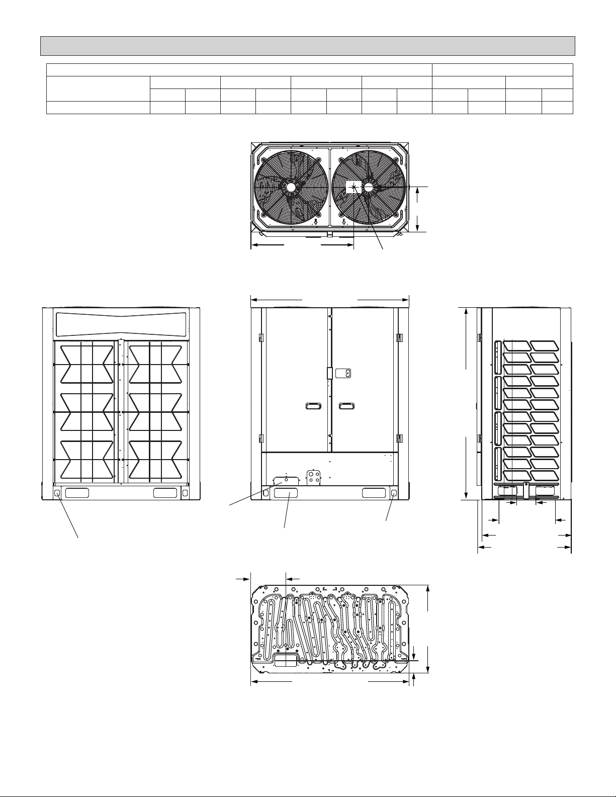
Unit Dimensions - inches (mm)
CORNER WEIGHTS CENTER OF GRAVITY
Model No. AA BB CC DD EE FF
lbs. kg lbs. kg lbs. kg lbs. kg in. mm in. mm
072, 096, 120 121 55 203 92 211 96 251 114 27-3/4 705 12-1/4 311
AA
DD
EE
TOP VIEW
52-3/4 (1340)
BB
FF
CC
CENTER OF
GRAVITY
64-3/8
(1635)
BACK VIEW
LAG BOLT DESIGNATION
(BOTH SIDES)
(TO ACCESS LAG BOLT)
PARALLEL MODULE
PIPING KNOCKOUT
FORKLIFT SLOT
REFRIGERANT LINE PATH
FRONT VIEW
(BOTH SIDES)
11-3/4 (298)
53-1/8 (1349)
BASE PAN VIEW
3
LIFTING HOLES
(BOTH SIDES)
(FOR RIGGING)
6-1/4 (159)
18-7/8 (479)
29-7/8 (759)
31-1/2 (800)
SIDE VIEW
29-1/2
(749)
4-1/8 (105)
Page 4
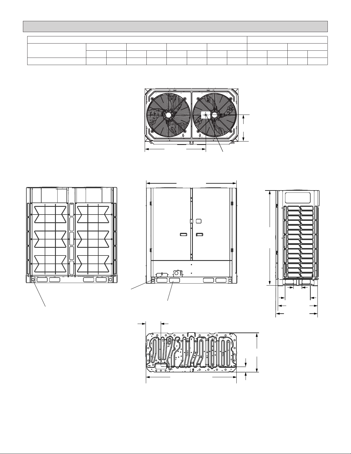
Unit Dimensions - inches (mm)
CORNER WEIGHTS CENTER OF GRAVITY
Model No. AA BB CC DD EE FF
lbs. kg lbs. kg lbs. kg lbs. kg in. mm in. mm
144, 168, 192 172 78 264 120 330 150 321 146 37-3/4 953 12 305
AA
DD
EE
TOP VIEW
68-1/2 (1740)
BB
FF
CC
CENTER OF
GRAVITY
72 (1829)
BACK VIEW
LAG BOLT DESIGNATION
(BOTH SIDES)
(TO ACCESS LAG BOLT)
PARALLEL MODULE
PIPING KNOCKOUT
REFRIGERANT LINE PATH
FRONT VIEW
FORKLIFT SLOT
(BOTH SIDES)
11-3/8 (289)
68-1/2 (1740)
BASE PAN VIEW
4
6-1/4 (159)
18-7/8 (479)
30 (762)
32-5/8 (829)
SIDE VIEW
29-3/4 (756)
4-1/8 (105)
Page 5
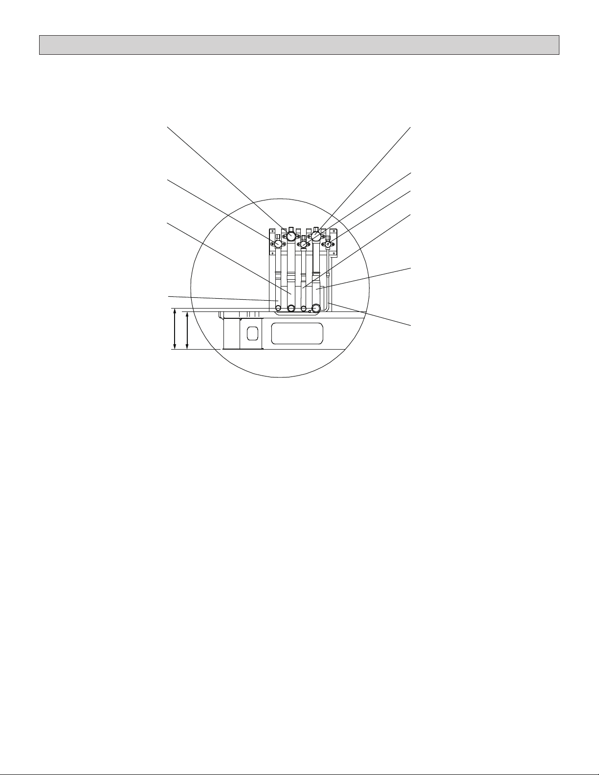
Dimensions - Piping Details - inches (mm)
Internal valve layouts are the same in both heat
recovery and heat pump units, it is their function that
is dierent. Pay close attention when making nal
piping connections.
Low pressure gas valve
High pressure
gas balance valve
Low pressure gas pipe
(1-1/8 in. diameter 072-120 sizes)
(1-3/8 in. diameter 144-192 sizes)
High pressure
gas balance pipe
(3/4 in. diameter)
6-1/4 (159)
5-5/8 (143)
Heat Recovery internal valve layouts are described
below. See the Heat Pump installation manual for
heat pump internal valve information.
High pressure gas valve
Liquid side valve
Liquid side valve
Oil balance valve
Liquid side pipe
(5/8 in. diameter 072-120 sizes)
(3/4 in. diameter 144-192 sizes)
High pressure gas pipe
(1-1/8 in. diameter 072-120 sizes)
(1-3/8 in. diameter 144-192 sizes)
Oil balance pipe
(1/4 in. diameter)
5
Page 6
Outdoor Unit Placement Considerations
!
WARNING
Use the provided and specied components
when installing equipment. Failure to do so may
result in unit falling, water leaking or electrical
shocks, caus ing personal injury or equipment
or property dam age.
Check stability of unit support. If sup port is
not capable of carrying weight of the unit, unit
may fall causing personal injury or equipment
damage.
Safely dispose of packing materials, which
include nails, wood and other sharp objects,
as well as plastic wrapping. Children playing
with plastic wrap or bags risk the danger of
suocation.
IMPORTANT!
Exhaust vents from dryers, water heaters and
furnaces should be directed away from the
outdoor unit. Prolonged exposure to exhaust
gases and the chemicals contained within
them may cause condensation to form on the
steel cabinet and other metal components of
the outdoor unit. This will diminish unit performance and longevity.
In addition to clearances, the following items should
be considered when setting the outdoor unit:
• 2007 EPA Noise Policy. Observe local code
adoptions/enforcement as consideration should
be used when selecting an outdoor unit’s permanent placement. Sound data for each unit can be
found in the Product Specications Document.
• Glass has a very high level of sound transmission. When possible, do not install the unit directly outside a window.
• Avoid installing the unit in areas exposed to ex-
treme voltage variations (such as factories).
• Install unit level.
• Allow sucient space around unit for proper operation and maintenance.
• Install the outdoor unit a minimum of 3 ft. (1 m)
away from any antenna, power cord (line), radio,
telephone, security system, or intercom. Electri-
cal interference and radio frequencies from any
of these sources may aect operation.
• Outdoor unit shall maintain a minimum distance
of 10 ft. (3 m) from dryer exhaust vents.
• Outdoor unit shall maintain a minimum distance
of 10 ft. (3 m) from Type 1 kitchen exhaust outlets.
• Coating outdoor coils is recommended in applications installed in coastal regions less than 30
miles (48 kilometers) inland.
6
Page 7

SINGLE ROW
Lifting the Unit
• Do not hold the air inlet grille while lifting the unit.
This could result in damage to the cabinet.
39 (991)
• Do not touch the fan blades with your hands or
other objects while lifting the unit.
Air Flow
Air Flow
31 (800)
39 (991)
39 (991)
Front Front
4 to 20 (102 to 508)
TWO ROWS
39 (991)
39 (991)
Front Front
39 (991)
Front Front
39 (991)
4 to 20 (102 to 508)
THREE OR MORE ROWS
FrontRear
Air Flow
Air Flow
31 (800)
39 (991)
39 (991)
39 (991)
39 (991)
39 (991)
Front Front
Air Flow
Front Front
Air Flow
31 (800)
Front Front
4 to 20 (102 to 508)
Figure 1. Installation Clearances - inches (mm)
7
Page 8
NOTICE
Drawings in this manual are for illustrative purposes
and should not be used as a template for fabricating
eld-supplied accessories or apparatuses. Consider
the environment in which this unit is being installed and
make necessary adjustments to ensure safe operation.
Local codes prevail.
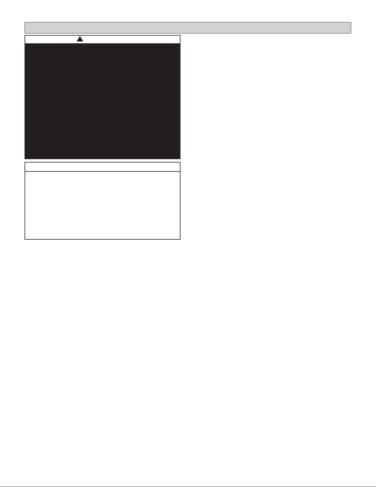
Clearances from Obstructions
• Allow adequate air ow clearance on all sides of
the unit. See Figure 1 and this section.
• Allow at least 39 in. (991 mm) clearance in front
of the unit for maintenance and service access.
The outdoor unit service access is via hinged
service doors that swing open in front of the unit.
Figure 2.
>39”
(991 mm)
Rear Side
Front Side
>32”
(813 mm)
Front SideRear Side
Figure 3. Perimeter Obstructions
• Allow at least 120 in. (3048 mm) clearance above
the unit. If an obstruction above the unit does not
allow for adequate clearance, a eld-supplied
discharge duct is required. The discharge duct
should be installed in such a way as to ensure
that discharge air goes beyond the obstruction
and does not cause recirculation of discharge air.
Ensure that the static capabilities of the outdoor
unit are not exceeded. Figure 4.
Figure 2. Maintenance & Service Clearance
• Perimeter obstructions that are 32 in. (813
mm) taller than the top of the outdoor unit
require a eld supplied air discharge duct
to avoid recirculation of discharge air.
The discharge duct should be installed to at
least the height of the surrounding obstructions
(for ex. walls) to ensure that discharge air
goes over the height of the obstruction.
Ensure that the static capabilities of the outdoor
unit are not exceeded. Figure 3.
!
CAUTION
In order to avoid injury, take proper precaution
when lifting heavy objects.
Take care when using a sling to lift the unit for
in stallation. The unit center of gravity is not at
its physical center.
>120”
(3048 mm)
Front Side Rear Side
Figure 4. Obstructions Above the Unit
8
Page 9
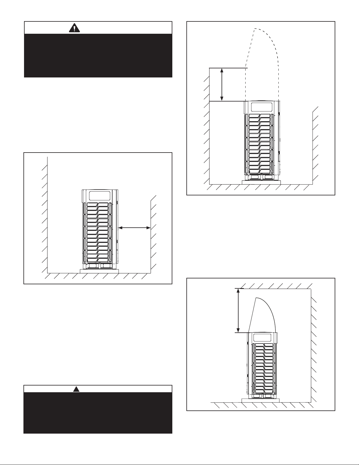
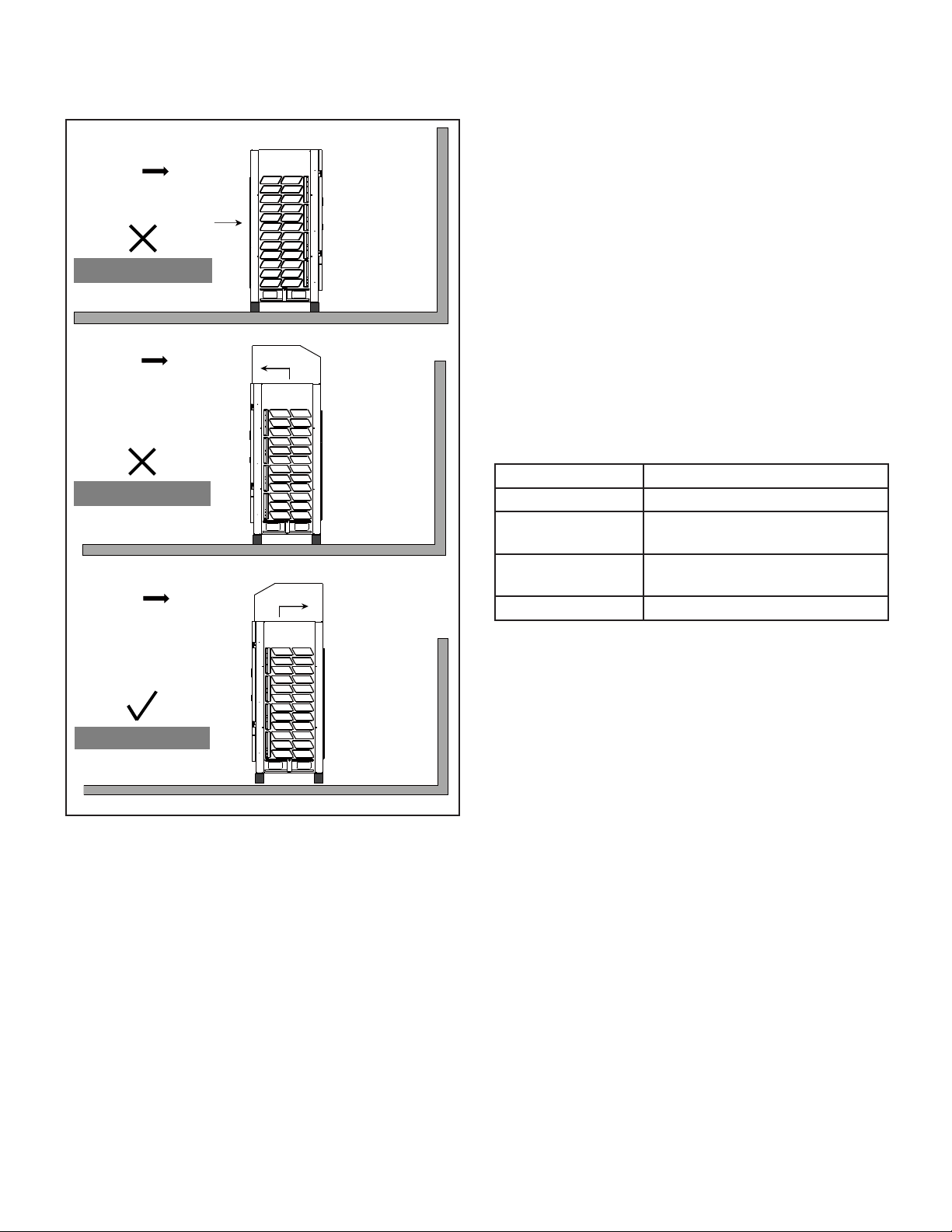
Cold Climate Considerations
Select a location where high winds and snow will not
aect the unit. In areas where typical ambient temperatures are below 50°F (10°C), the following pre-
cautions should be observed.
• Locate unit away from overhanging roof lines
which would allow water or ice to drop on, or in
front of, coil or into unit.
Eaves
Icicle
Wrong Installation
• Install snow guards to prevent snow fall from entering air inlet and outlet.
Correct Installation
Snow
Guard
Kit
Snow level
Wrong Installation
Snow
Guard
Kit
RearFrontRearFront
Snow level
RearFront
Figure 5. Do Not Locate Under Roof Overhang
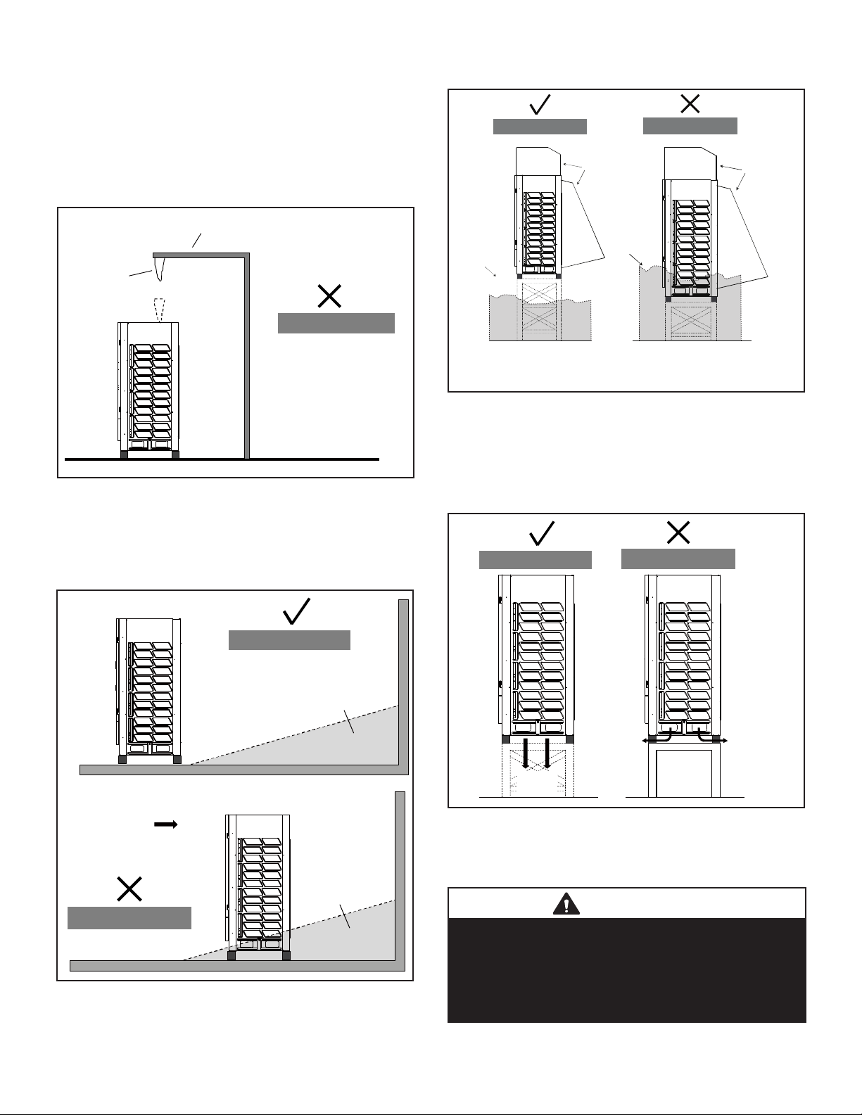
• The unit base should be elevated above the
depth of average snows plus 12 in. (305 mm). In
heavy snow areas, do not locate the unit where
drifting will occur.
Correct Installation
RearFront
Snow Drifts
NOTE - Snow guards are recommended on both sides
and rear of the unit as shown in this example.
Figure 7. Elevate Above Average Snow Level
& Protect Coil
• If necessary, install the unit on a raised base
made of angle iron and that allows snow and
wind to pass through
Correct Installation
RearFront
Wrong Installation
Defrost
Water
RearFront
Defrost
Water
Wind
RearFront
Snowdrift
Wrong Installation
Figure 6. Do Not Locate Where Drifting Will Occur
Defrost
Water
Figure 8. Secure Unit to
Weather Resistant Support
IMPORTANT
These illustrations are examples of possible snow
protection options. They should not be used as a
template for fabricating the snow protection apparatuses.
Consider the environment in which this unit is being
installed and make necessary adjustments to ensure
safe operation.
9
Page 10
• When installed in areas where low ambient tem-
peratures exist, locate unit so winter prevailing
winds do not blow directly on to the outdoor unit.
Wind
Rear Front
Wind
Wind
Inlet
Outlet
RearFront
Outlet
llation
Wrong Installation
Wrong Installation
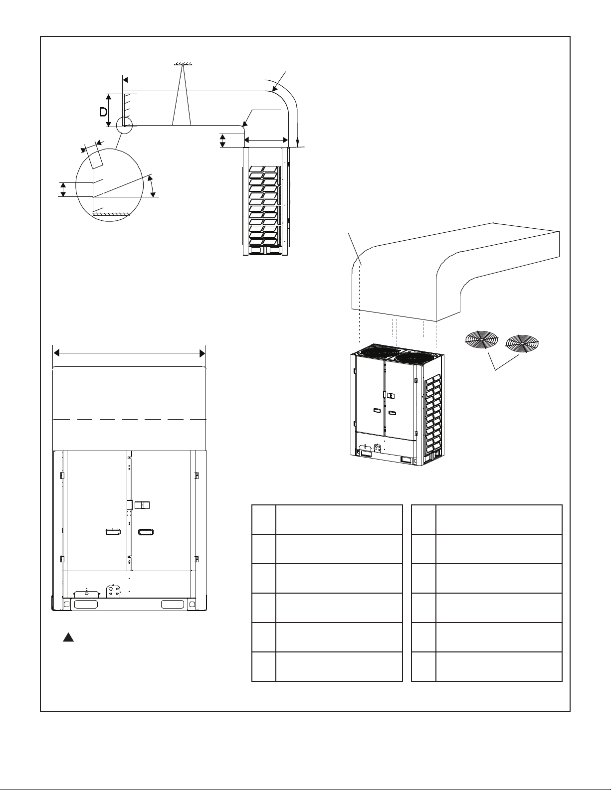
Air Discharge Duct
• Before installing the air duct, remove the two fan
guards from the top of the unit.
• Duct each outdoor unit separately. Do not use
a combined plenum as this may result in air not
being discharged directly to the outside.
• Discharge air duct shall be constructed of steel
and installed in a manner which prevents sagging
and or collapsing.
• Only one bend is allowed in the air duct.
• Duct louvers will reduce air volume, cooling and
heating capacity and eciency. Louvers are not
recommended; if they are required by the job,
the louver angle should be no larger than 15°.
• It may be necessary to install a exible connector
between the unit and the duct to reduce vibration
noise.
Table 1. Static Pressure Settings
Static Pressure Description
0 WG (0 Pa) Default
0-0.08 WG (0-20
Pa)
Above 0.08 WG
(20 Pa)
Remove fan guard, < 10 ft. (3 m)
duct length
Contact Lennox VRF Applications
Support
RearFront
Correct Installation
Figure 9. Protect Unit from Prevailing Winds
NOTE - Use dip switch S4 to change outdoor
unit static pressure settings.
10
Page 11
Support
C
Radius
E
A
Radius
3-1/2 in.
(89 mm)
≤ 15°
4 in. (102 mm)
Air Outlet Louver
072, 096, 120 -- 50-3/4 in. (1289 mm)
144, 168, 192 -- 65 in. (1651 mm)
B
F
8 × ST3.9
self-threading screws
Fan guards
(remove
first)
!
Contact the Lennox VRF
applications department for
assistance with ducting applications
that dier from these images.
Figure 10. Air Discharge Duct
072, 096, 120
A A ≥ 12 in.(305 mm)
B B ≥ 10 in. (254 mm)
C C ≤ 118-1/8 in. (3000 mm)
D D ≥ 24 in. (610 mm)
E E = A + 24 in. (610 mm)
F 24 in. (610 mm)
(Front or Rear Connection)
11
144, 168, 192
A A ≥ 12 in.(305 mm)
B B ≥ 10 in. (254 mm)
C C ≤ 118-1/8 in. (3000 mm)
D D ≥ 28-3/8 in. (721 mm)
E E = A + 24 in. (610 mm)
F 28-3/8 in. (721 mm)
Page 12
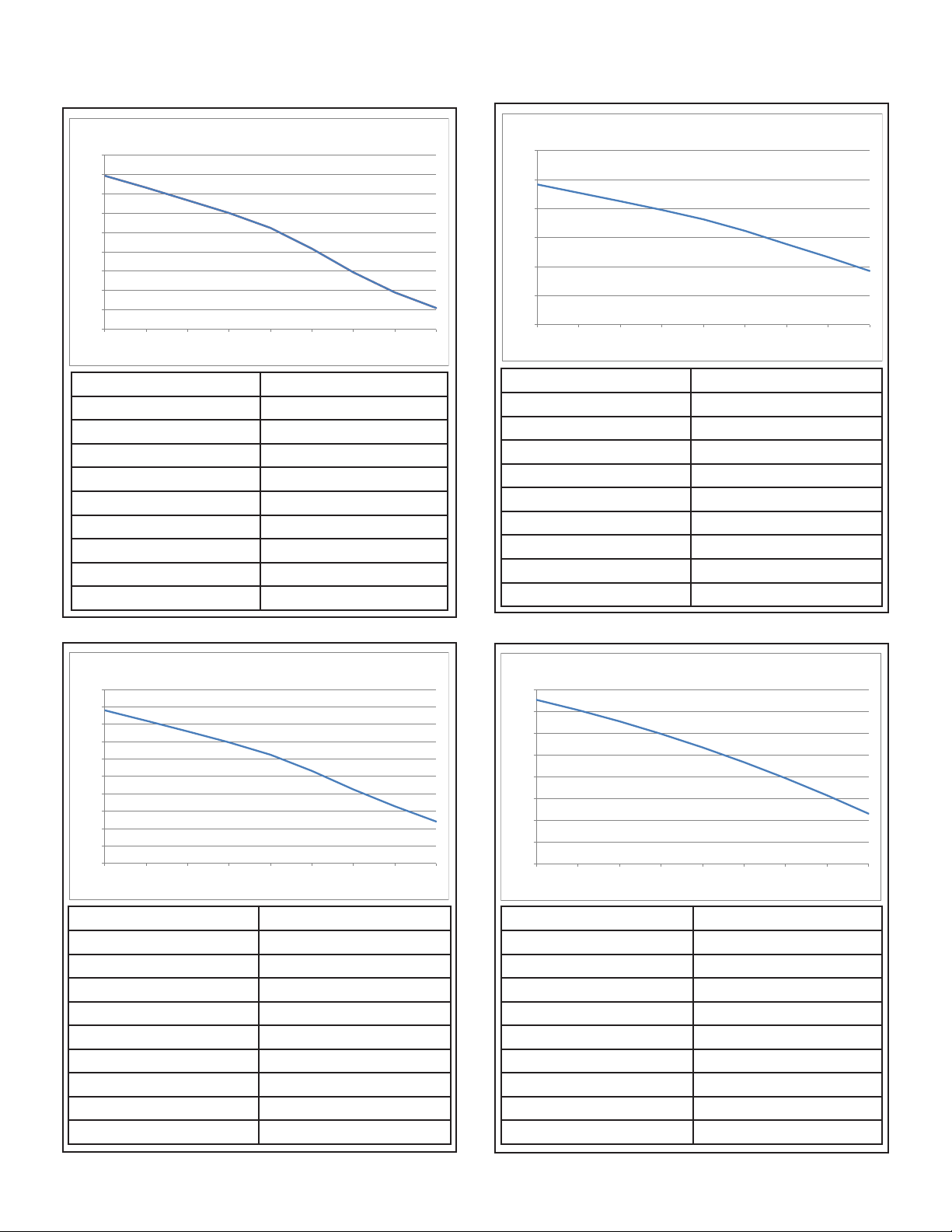
Discharge Duct Pressure Curves
VRB072
VRB120
6-ton Air Volume (CFM)
15000
14000
13000
12000
11000
10000
9000
8000
7000
6000
0 0.04 0.08 0.1 2 0.16 0.2 0.24 0.2 8 0.32
Static Pressure (in.wg.) Air Volume (CFM)
0 13934
0.04 13320
0.08 12667
0.12 12010
0.16 11236
0.2 10163
0.24 8940
0.28 7902
0.32 7094
10-ton Air Volume (CFM)
18000
16000
14000
12000
10000
8000
6000
0 0.04 0.08 0.12 0.16 0.2 0.24 0.28 0.32
Static Pressure (in.wg.) Air Volume (CFM)
0 15667
0.04 15090
0.08 14508
0.12 13907
0.16 13261
0.2 12467
0.24 11554
0.28 10655
0.32 9709
VRB096
8-ton Air Volume (CFM)
16000
15000
14000
13000
12000
11000
10000
9000
8000
7000
6000
0 0.04 0.08 0.12 0.16 0.2 0.24 0.28 0.32
Static Pressure (in.wg.) Air Volume (CFM)
0 14800
0.04 14205
0.08 13587
0.12 12958
0.16 12248
0.2 11315
0.24 10247
0.28 9279
0.32 8402
VRB144, 168, & 192
12~16-ton Air Volume (CFM)
25000
24000
23000
22000
21000
20000
19000
18000
17000
0 0.04 0.08 0.12 0.16 0.2 0.24 0.28 0.32
Static Pressure (in.wg.) Air Volume (CFM)
0 24544
0.04 24079
0.08 23559
0.12 22986
0.16 22360
0.2 21679
0.24 20945
0.28 20157
0.32 19315
12
Page 13
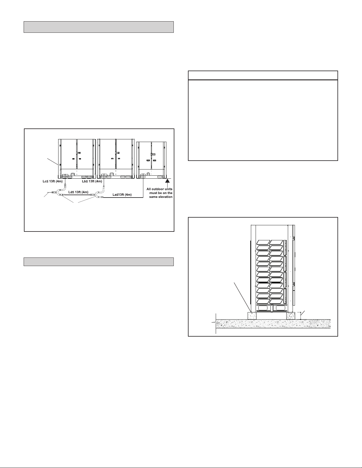
Main/Sub Outdoor Unit Placement
• A VRF system consisting of more than two
outdoor units must be placed in order from the
largest to the smallest capacity. See gure 8.
• The largest capacity outdoor unit must be
installed closest to the main pipe leading into the
building. See Figure 11.
• The largest capacity outdoor unit address is the
main unit, while the others are the sub units. See
Figure 11.
• All of the outdoor units manifolded together
should be installed at the same elevation.
Main unit
placed
closest to
main pipe
leading into
building
Main piping
to building
16-ton
Outdoor Unit
Branch Pipe Kits
14-ton 10-ton
NOTE - All of the outdoor units manifolded
together should be installed at the same elevation.
• If the unit coil cannot be installed away from
prevailing winter winds, a wind barrier should
be constructed. Size barrier at least the same
height and width as outdoor unit. Install barrier
12 inches (305 mm) minimum from the sides of
the unit in the direction of prevailing winds.
IMPORTANT!
Roof Damage!
This system contains both refrigerant and
oil. Some rubber roong material may absorb
oil. This will cause the rubber to swell when
it comes into contact with oil. The rubber will
then bubble and could cause leaks. Protect the
roof surface to avoid expo sure to refrigerant
and oil during service and instal lation. Failure
to follow this notice could result in damage to
roof surface.
Securing Outdoor Unit to Slab or Frame
Use lag bolts (min. 3/8 in.) at all four corners to
secure the unit to the eld-provided slab or frame.
Isolation material can be used to control vibration or
sound transmission. Lag bolts must extend through
material to the slab or frame. See Figure 12.
Figure 11. Main/Sub Unit Placement
(40-Ton System Example)
Installation
Slab or Roof Mounting
Install the unit a minimum of 8 inches (203 mm)
above the roof or ground surface to avoid ice buildup around the unit. Locate the unit above a loadbearing area of the roof that can adequately support
the unit. Consult local codes for rooftop applications.
• Use a eld supplied slab or suitably sized
steelwork to construct a base for locating
the condensing unit. All supporting work
should be veried by a qualied engineer.
NOTE - Prefabricated light duty equipment pads
are NOT suitable for use.
• Support the unit across the front and back of the
unit.
Use lag
bolts (4) to
secure unit
to slab or
approved frame
at each corner
8 in.
(203 mm)
Figure 12. Secure Outdoor Unit
to Approved Structure
13
Page 14
Refrigerant Piping Connections
!
WARNING
Refrigerant leaks are unlikely; however, if a
refriger ant leak occurs, open a door or windows
to dilute the refrigerant in the room. Turn o the
unit and all other appliances that may cause
a spark. Call a li censed professional HVAC
technician (or equiva lent) to repair the leak.
Use only R-410A refrigerant to charge this
system. Use of other refrigerant or gas will
damage the equipment.
Do not allow air or other contaminants to
enter sys tem during installation of refrigerant
piping. Con taminants will result in lower
system capacity and abnormally high operating
pressures and may res ult in system failure or
explosion.
Insulate all refrigerant piping.
Refrigerant pipes may be very hot during unit
opera tion. Do not allow contact between wiring
and bare copper pipes.
After refrigerant piping connections have been
completed, check the system for leaks per
commis sioning instructions.
• Both liquid and gas (vapor) lines must be indi-
vidually insulated.
• Field piping consists of three HVAC/R eld-pro-
vided copper refrigerant lines connected to the
outdoor unit. These lines carry the liquid and vapor refrigerant to and from the mode selection
box(es).
• Refrigerant piping and wiring connections can be
brought into the outdoor unit through openings
provided in the front, side(s), or underside (recommended) of the unit.
• Refrigerant piping must be connected using
mode selection boxes and individual branch pipe
kits. Six mode selection boxes are available in
varying sizes to accommodate connection of one
to 41 indoor units.
• The following restrictions apply to each VRB system:
• Total refrigerant pipe length 3280 ft. (1000 m)
• Longest pipe length actual) 574 ft. (175 m)
• Level dierence between indoor units 98 ft.
(30 m)
• Piping length from the rst branch pipe to the
farthest indoor unit 132/295 ft. (40/90 m)
• For each branch pipe, allow 20” (508 mm) of
equivalent length.
!
Contact the Lennox VRF applications department
for assistance.
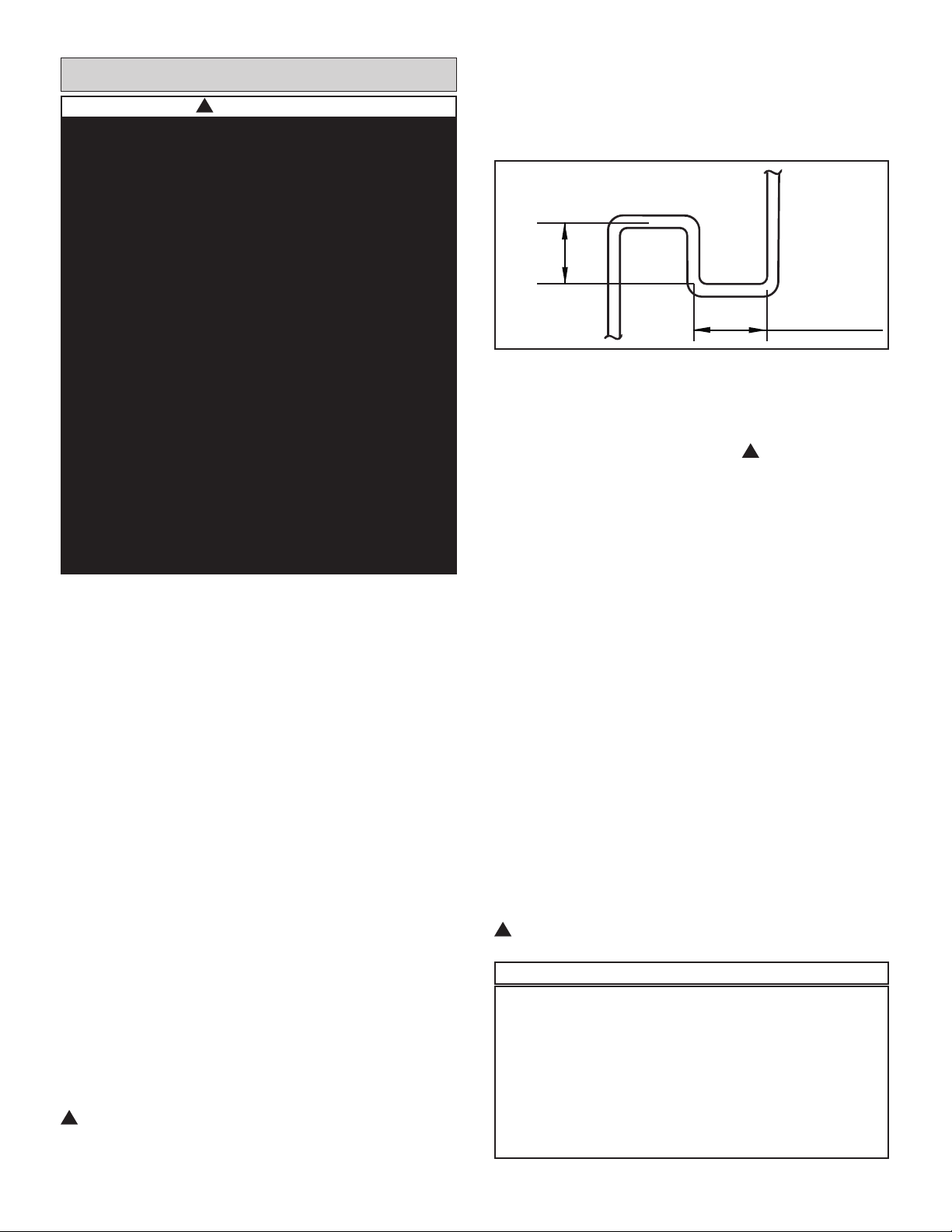
• When the outdoor unit is installed 164 feet (50
m) or more above the indoor units, install an oil
return trap every 33 feet (10 m) in the main low
pressure gas pipe. See Figure 13 for trap speci-
cations.
≥1ft
≥1ft
Figure 13. Oil Return Trap
• When the outdoor unit is 132 feet (40 m) or more
below the indoor units, increase the diameter of
the liquid line pipe from the outdoor unit to the
rst branch pipe by one size. ! Contact the Lennox VRF applications department for assistance.
• To extend the length from the rst branch pipe to
the farthest indoor unit beyond 132 ft. (40 m) and
up to 295 ft. (90 m), the following three conditions
must be met.
1. Increase diameter of the main pipe between
the rst and the last branch pipes. If the diameter of the pipe is the same as the main outdoor
pipe, then it does not need to be increased.
Ex: If 132 ft.<L1+L7+L9+L10 ≤ 295 ft., in-
crease the diameter of all the pipes by one
size.
2. The length from the indoor unit to the nearest
branch pipe must be 132 ft. (40 m) or less.
Ex: a,b,c,d,e,f,g,h,i,j,k,l,m ≤ 132 ft.
3. The dierence between [the distance from
the outdoor unit to the farthest indoor
unit] and [the distance from the outdoor
unit to the nearest indoor unit] is ≤132 ft.
Ex:(L1+L7+L9+L11+11+j+k+n)
-(L1+L7+L8+p)
≤ 132 ft.
!
Contact the Lennox VRF applications department
for assistance.
IMPORTANT!
The compressor in this unit contains PVE oil
(Polyvinylether). PVE oil is formulated for hy-
drouorocarbon (HFC) refrigerants, such as R-
410a, which this system contains. While it may
have some miscibility properties with mineral
based oil and POE oil (Polyolester), you should
not mix PVE oil with any other type of refrigerant oil.
14
Page 15

Maximum Permitted Refrigerant Pipe Length and Maximum Height Difference
OUTDOOR UNITS
(one or more outdoor units)
NOTE - Capacities are shown in parenthesis
a
b
c
MS1
L1
A
L2
L3
B
L4
C
L6
L5
MS3
MS2
INDOOR UNITS
N1
(024)
N2
(024)
d
e
The first line Branch Pipe
N4
(009)
N3
(048)
Maximum equivalent single piping length - 656 ft.(200 m)
L7
Maximum piping length from the first Branch Pipe
joint to the farthest indoor unit - 295 ft. (90 m)
LEGEND
Branch Pipe
Mode Selection
Box (MS)
Maximum level difference between
Indoor Unit
L8
D
L9
L10
E
L11
F
MS6
Indoor Unit and Outdoor Unit - 361 ft. (110 m)
MS7
f
MS4
L12
MS5
L13
Maximum piping length from MS Device
to downstream indoor unit - 131 ft. (40 m)
k
j
r
N13
(018)
q
N12
(048)
p
N11
(048)
l
N5
(048)
g
i
m n
N8
(009)
h
N9
(018)
N6
(024)
N7
(024)
N10
(018)
Maximum level difference between indoor units - 98 ft. (30 m)
Piping Length Permitted value Piping
Total piping length
Single piping length
Piping length from the rst branch joint to the
Piping
Length
farthest indoor unit
Actual length 574 ft. (175 m)
Equivalent length2 656 ft. (200 m)
Piping length from Mode Selection Box (MS) to
the downstream indoor unit of itself
Level dierence between
indoor unit and outdoor unit
Level
Level dierence between indoor units 98 ft. (30 m) - - -
Dierence
NOTES:
The rst branch in all systems must be centrally located between all Mode Selection (MS) Boxes.
1
When counting the total piping length, double the actual length of the distribution pipes between rst Branch Pipe joint and Mode Selection Box (MS): Installation.
Total piping length = L1+(L2+L3+L4+L5+L6+L7+L8+L9+L10+L11+L12+L13)×2+a+b+c+d+e+f+g+h+i+j+k+l+m+n+p+q+r ≤ 3280 ft.(1000 m).
2
Each Branch Pipe or bend is equivalent to 20 in. (508 mm).
3
The maximum allowable piping length from the rst Branch Pipe joint to the farthest indoor unit must be ≤ 132 ft. (40 m), but if the following conditions are met, the
maximum allowable length can be extended to 295 ft. (90 m):
• The piping length from each indoor unit to the nearest Branch Pipe joint or direct connected Mode Selection Box (MS) must be less than 132 ft. (40m) (b to r).
• The dierence in length between the outdoor unit to the farthest indoor unit, and the outdoor unit to the nearest indoor unit is ≤ 132 ft. (40 m).
Example: The farthest indoor unit is N10, The nearest indoor unit is N11 (L1+L7+L9+L11+j+k+n) minus (L1+L7+L8+p) ≤ 132 ft. (40 m).
• Increase the distribution pipe diameter between the rst Branch Pipe and Mode Selection Box (MS) L2-L13. If the pipe diameter is the same as the main outdoor pipe,
it does not need to be increased.
Pipe Size Allowable Increase Diameters (in.):
3/8 to 1/2 1/2 to 5/8 5/8 to 3/4 3/4 to 7/8 7/8 to 1-1/8 1-1/8 to 1-3/8 1-3/8 to 1-5/8 1-5/8 to 2-1/8
4
When the outdoor unit is higher than indoor units and the level dierence is over 164 ft. (50 m), it is required to set an oil return bend every 33 ft.(10 m) in the gas pipe of
the main pipe. Refer to Installation Instructions for additional details.
5
When the outdoor unit is lower than indoor units and the level dierence is more than 132 ft.(40 m), the main liquid pipe pipe need to increase by one size.
Outdoor unit up4 360 ft. (110 m) - - -
Outdoor unit down
1
3280 ft. (1000 m)
3
132/295 ft. (40/90 m) L7+L9+L11+j+k+n
132 ft. (40 m) j+k+n
5
230 ft. (70 m) - - -
L1+(L2+L3+L4+L5+L6+L7+L8+L9+L10+L11+L12+L1
3)×2+a+b+c+d+e+f+g+h+i+j+k+l+m+n+p+q+r
L1+L7+L9+L11+j+k+n
15
Page 16

(120)
(144)
Lead ODU
g3 g2 g1
LEGEND
Branch Pipe
Mode Selection
Box (MS)
Indoor Unit
(192)
G1
r
NOTE - Indoor and outdoor unit
capacities are shown in parenthesis.
L2
A
L1
L7
D
L9L8
L10
E
L11
MS7
N13
(018)
q
N12
(048)
p
N11
(048)
B
F
MS6
j
L3
L4
L12
L13
a
MS1
C
f
MS4
MS5
k
l
L6
b
c
MS2
L5
MS3
(009)
N5
(048)
g
i
m n
N8
(009)
N4
d
h
N9
(018)
(024)
(048)
e
N3
(048)
N6
(048)
N7
(024)
N1
N2
N10
(018)
PIPE AND COMPONENT NAMES
Name Designation
Outdoor Unit Connection Pipe g1, g2, g3, G1
Outdoor Unit Branch Pipe Assembly L, M
Main Pipe⁶ L1
Indoor Unit Main Pipe L2, L3, L4, L5, L6, L7, L8, L9, L10, L11, L12, L13
Branch Pipe Assembly between Main Pipe and Mode Selection Box (MS) A, B, C, D, E, F
Mode Selection Box (MS) MS1, MS2, MS3, etc.
Branch Pipe Assembly between Mode Selection Box (MS) and Indoor Unit I, II, III, IV
Indoor Unit auxiliary pipe between Mode Selection Box (MS) and downstream
Branch Pipe joint
Indoor Unit auxiliary pipe from Indoor Unit to the nearest Branch Pipe joint or
direct connected Mode Selection Box (MS)
Indoor Unit N1, N2, N3, etc.
⁶ When the length of main pipe L1 is larger than 230 ft. (70m), the dip switch S9-2 should be ON.
a, g, j, k
b, c, d, e, f, h, i, l, m, n, p, q, r
Figure 14. Typical Refrigerant Piping Diagram
INDOOR UNIT AUXILIARY PIPE SELECTION
(From Indoor Unit To The Nearest Branch Joint (a, b, c, d, e, f, g, h, i, j, k, l, m)
Pipe Diameter (in.)
Indoor Unit
Capacity (kBtuh)
A<18 1/2 1/4 5/8 1/4
18≤A≤54 5/8 3/8 3/4 3/8
54<A≤96 7/8 3/8 1-1/8 3/8
Pipe length less than 100 ft (30 m) Pipe length more than 100 ft (30 m)
Gas Pipe Liquid Pipe Gas Pipe Liquid Pipe
Pipe length from indoor unit to nearest branch joint
16
Page 17

OUTDOOR UNIT MAIN PIPE SELECTION (L1)
Main Pipe Diameter (in.)
Outdoor
Unit
Size
Equivalent length of all liquid pipes
is less than 295 ft. (90 m)
Low
Pressure
Gas Pipe
High
Pressure
Gas Pipe
Liquid
Pipe
First
Branch
Pipe
Assembly
Equivalent length of all liquid pipes
is more than 295 ft. (90 m)
Low
Pressure
Gas Pipe
High
Pressure
Gas Pipe
Liquid
Pipe
First
Branch
Pipe
Assembly
072 7/8 3/4 3/8 V8MSBP02 7/8 3/4 1/2 V8MSBP02
096 7/8 3/4 3/8 V8MSBP02 7/8 3/4 1/2 V8MSBP02
120 1-1/8 3/4 1/2 V8MSBP03 1-1/8 3/4 5/8 V8MSBP03
144 1-1/8 7/8 1/2 V8MSBP03 1-1/8 7/8 5/8 V8MSBP03
168-216 1-3/8 1-1/8 5/8 V8MSBP04 1-3/8 1-1/8 3/4 V8MSBP04
240 1-3/8 1-1/8 5/8 V8MSBP04 1-3/8 1-1/8 3/4 V8MSBP04
264-312 1-3/8 1-1/8 3/4 V8MSBP04 1-3/8 1-1/8 7/8 V8MSBP04
336-432 1-5/8 1-3/8 3/4 V8MSBP05 1-5/8 1-3/8 7/8 V8MSBP05
432~ 1-5/8 1-3/8 3/4 V8MSBP05 1-5/8 1-3/8 7/8 V8MSBP05
Note - The Main Pipe (L1) can be selected from the Outdoor Unit Main Pipe Selection table or the Indoor Unit Main Pipe Selection table, the larger size must be used.
INDOOR UNIT MAIN PIPE SELECTION (L1 to L13)
Indoor Unit
Total Capacity
(kBtuh)
Low Pressure
Gas Pipe
Indoor Unit Main Pipe Diameter (in.)
High Pressure
Gas Pipe
Liquid Pipe
Branch Pipe
Assembly
A < 018 1/2 3/8 1/4 V8MSBP01
018 ≤ A < 056 3/4 5/8 3/8 V8MSBP01
056 ≤ A < 078 7/8 3/4 3/8 V8MSBP02
078 ≤ A < 112 7/8 3/4 1/2 V8MSBP02
112 ≤ A < 156 1-1/8 7/8 1/2 V8MSBP03
156 ≤ A < 224 1-1/8 7/8 5/8 V8MSBP03
224 ≤ A < 314 1-3/8 1-1/8 3/4 V8MSBP04
314 ≤ A < 460 1-5/8 1-3/8 3/4 V8MSBP05
460 ≤A 1-5/8 1-3/8 7/8 V8MSBP05
OUTDOOR UNIT PIPE SELECTION (g1, g2, g3, G1)
Pipe
Outdoor Unit
Size
Low Pressure Gas Pipe High Pressure Gas Pipe Liquid Pipe
Pipe Diameter (in.)
G1 408, 432, 456, 480, 504 1-5/8 1-3/8 7/8
6 or 8-ton 7/8 3/4 1/2
g1, g2, g3
10 or 12-ton 1-1/8 7/8 5/8
14 or 16-ton 1-3/8 1-1/8 3/4
OUTDOOR UNIT BRANCH PIPE ASSEMBLY SELECTION (L, M)
Outdoor Unit Quantity Parallel Connection with Branch Pipes
2 units L use V8ODBP02HR-3
3 units L + M use V8ODBP03HR-3
INDOOR UNIT AUXILIARY PIPE SELECTION (Between Branch Box (MS) And Downstream Branch Joint) (a, g, j, k)
Indoor Unit Capacity (kBtuh)
Gas Pipe Liquid Pipe
Pipe Diameter (in.)
Available Branch Pipe
A<56 5/8 3/8 V8IDBP01
17
Page 18

Name Gas Side Joints (inch) Liquid Side Joints (inch)
Insulation
Material
(furnished)
V8IDBP01
V8IDBP02
V8IDBP03
,'
,'
,'
,'
,'
,'
,'
,'
,'
,'
,'
,'
2'
,'
,'
2'
2'
2'
2'
2'
,'
,'
,'
2'
2'
2'
,'
,'
,'
,'
,'
,'
,'
,'
,'
,'
,'
,'
,'
2'
,'
,'
,'
,'
,'
2'
2'
2'
2'
,'
2'
,'
,'
2'
2'
2'
,'
,'
,'
,'
(2 sets)
,'
(2 sets)
(2 sets)
V8IDBP04
V8IDBP05
,'
,'
,'
,'
,'
,'
2'
,'
,'
,'
2'
,'
,'
,'
2'
2'
,'
,'
,'
,'
,'
,'
,'
,'
,'
,'
,'
,'
2'
,'
2'
2'
2'
Figure 15. Indoor Unit Branch Pipe Kits
,'
,'
2'
2'
,'
,'
,'
(2 sets)
,'
(2 sets)
18
Page 19

(Liquid side used)
(Liquid side used)
Low-pressure
side used
High-pressure
side used
Liquid
side used
V8MSBP01
V8MSBP02
V8MSBP03
V8MSBP04
V8MSBP05
OD:1/2
ID:1/4
ID:3/8
OD:1/2
OD:1/2
ID:1/2
ID:3/8
ID:1/2
ID:1/4
ID:3/8
ID:5/8
OD:5/8
ID:3/4
(ID:1/2)
OD:5/8
ID:3/8
ID:5/8
(ID:1/2)
OD:5/8
ID:3/8
ID:1/4
ID:5/8
OD:5/8
ID:3/4
(ID:1/2)
OD:5/8
ID:3/8
ID:5/8
(ID:1/2)
OD:5/8
ID:3/8
ID:1/4
ID:1-3/8
ID:1-5/8
ID:1-3/8
ID:1-5/8
ID:1-5/8
ID:1-3/4
ID:1-3/4
OD:1-5/8
ID:1-1/8
ID:1-1/4
OD:1-1/8
ID:1-1/8
ID:3/4
ID:7/8
OD:1-1/8
ID:3/4
ID:7/8
OD:1-1/8
ID:5/8
ID:1-1/8
ID:1-1/4
OD:1-1/8
ID:1-1/8
ID:3/4
ID:7/8
OD:1-1/8
ID:3/4
ID:7/8
OD:1-1/8
ID:5/8
ID:5/8
(ID:3/4)
OD:7/8
ID:7/8
OD:7/8
ID:7/8
ID:1
ID:5/8
(ID:3/4)
OD:7/8
ID:1/2
ID:5/8
(ID:3/4)
OD:7/8
ID:7/8
OD:7/8
ID:7/8
ID:1
ID:5/8
(ID:3/4)
OD:7/8
ID:1/2
ID:5/8
(ID:3/4)
OD:7/8
ID:7/8
OD:7/8
ID:7/8
ID:1
ID:5/8
(ID:3/4)
OD:7/8
ID:1/2
ID:1/2
(ID:5/8)
OD:3/4
ID:3/4
OD:3/4
ID:3/4
ID:7/8
ID:1/2
(ID:5/8)
OD:3/4
ID:3/8
ID:1/2
(ID:5/8)
OD:3/4
ID:3/4
OD:3/4
ID:3/4
ID:5/8
ID:1/2
(ID:5/8)
OD:3/4
ID:1/2
(ID:5/8)
OD:3/4
ID:3/4
OD:3/4
ID:3/4
ID:5/8
ID:1/2
(ID:5/8)
OD:3/4
ID:3/4
ID:7/8
ID:1-1/8
OD:1-3/8
ID:1-3/8
OD:1-3/8
ID:1-1/2
ID:7/8
ID:1-1/8
OD:1-3/8
ID:1-3/8
ID:3/4
ID:7/8
ID:1-1/8
OD:1-3/8
ID:1-3/8
OD:1-3/8
ID:1-1/2
ID:7/8
ID:1-1/8
OD:1-3/8
ID:1-3/8
OD:1/2
ID:3/8
ID:3/8
ID:1/4
OD:3/8
ID:1/4
OD:3/8
ID:3/8
Name
Low-Pressure Gas Side Joints - Inch High-Pressure Gas Side Joints - Inch Liquid Side Joints - Inch
Insulation
Material
(furnished)
(3 sets)
(3 sets)
(3 sets)
(3 sets)
(3 sets)
Adapter Pipe - Inch
OD:5/8
ID:1/2
ID:1/2
ID:3/4
OD:7/8
ID:5/8
OD:3/4
OD:3/8
ID:1/4
ID:3/8
ID:1/2
ID:5/8
OD:3/4
Figure 16. Mode Selection Box Branch Pipe Kits
19
Page 20

Horizontal Runs
°
°
Horizontal Surface
When installed horizontally, these branch pipe kits
MUST be installed level +/- 10°.
CorrectWrong
10
10
Figure 17. Horizontal Installation
Vertical Runs
When installed vertically, mode selection branch
kits MUST be installed straight up or straight down.
Vertical Surface
Indoor unit branch kits have graduated piping diameters.
• The piping can be cut to suit the installation
needs. See figure 19.
• Use a pipe cutter designed for refrigeration tubing to cut pipe.
• Discard unused pipe.
3/4” Refrigerant Pipe
No Cut Needed
OD:1-1/8
ID:7/8
ID:3/4
7/8” Refrigerant Pipe
ID:5/8
ID:3/4
ID:7/8
OD:1-1/8
Cut Here
Be sure to maximize the total
length of the socket to ensure a
good joint
Figure 19. Vertical Installation
IMPORTANT
Locate rst branch pipe kit of the system centrally
to ensure correct distribution of refrigerant.
• Refer to the Lennox VRF Selection Software
(LVSS) pipe sizing diagram to obtain the correct
inlet and outlet sizes for the installation.
• Keep all components sealed until brazing.
ID:1-1/8
OD:1-1/8
ID:1-1/8
ID:1-1/4
1-1/8” Refrigerant Pipe
Cut Here
Be sure to maximize the total
length of the socket to ensure a
good joint
Figure 18. Cutting Branch Pipe Kits to Size Example
20
Page 21

Branch Pipe Kit Placement
Provide 24 to 36 inches of straight pipe before and
after each branch pipe kit to avoid creating refriger-
ant turbulence and ash points. Failure to follow 24
inch minimum guideline can lead to reduced capacity and equipment damage.
CONTINUE
REFRIGERANT
PIPING
24” REQUIRED
36” PREFERRED
CAUTION
24 inches (588 mm) minimum straight pipe required
before and after branch pipe kit to prevent capacity
loss, refrigerant hammering and equipment
damage.
FROM
OUTDOOR UNIT
24” REQUIRED
36” PREFERRED
FIRST ELBOW OR
BRANCH PIPE
CONNECTION
TO INDOOR UNIT OR
MS BOX
Figure 20. 24 to 36” of Straight Pipe Before and After Branch Pipe Kit
21
Page 22

12 34 5
66
• The seal on the unit refrigerant piping connections should remain in place until the last possible moment. This will prevent dust or water
from getting into the refrigerant piping before it
is connected.
• Flow the pipework with dry (oxygen-free) nitro-
gen (2.9 psig or 3 CFH) during brazing to avoid
oxidation which may block the refrigerant piping.
• Do not use ux when brazing copper-to-copper
piping. Use phosphor copper brazing ller alloy
(BCuP) which does not require ux. Flux has a
harmful eect on refrigerant pipe.
• Use a wet cloth to insulate the shut o valve dur-
ing brazing.
• Use dedicated gauges and hoses with R-410A
equipment.
IMPORTANT!
Use only oxygen-free nitrogen (OFN).
Table 2. Pressure Test Specications
1 3 bar 44 psig minimum of 10 minutes
2 15 bar 220 psig minimum of 10 minutes
3 32 bar 470 psig minimum of 10 minutes
4 45 bar 500 psig 1 hour. Stress test to
prove the integrity of the
complete installation.
5 32 bar 470 psig 24 hours. Lower system
pressure test, after
conrmation No. 4 was
successfully completed.
Pressure Test
• Follow the pressure test specications in Table 2
for proper pressure testing procedures.
• Ensure the unit service valves are fully closed
and haven’t become loose during transportation.
• Use oxygen-free nitrogen to pressure test to 650
psig and hold for 1 hour.
Evacuate System
• Follow the Lennox pressure test specications
in table 1 and the triple evacuation process described on this page to pressure test and evacuate the system.
• Use a vacuum pump capable of evacuating to
lower than 500 Microns (0.5 Torr).
• Do not open any of the outdoor unit shut-o
valves (possible max 5 valves). The outdoor unit
does not need to be evacuated.
• Evacuate the system to 500 Microns (0.5 Torr), or
below, for 4 hours.
Triple Evacuation Procedure
A Micron or Torr gauge must be used for this
procedure.
1. Discharge the oxygen-free nitrogen and evacuate
the system to a reading of 8000 Microns (8 Torr)
using all service valves.
2. Break the vacuum by allowing nitrogen into the
three inter-connecting pipework port connections
(low pressure gas pipe, high pressure gas pipe
and liquid line pipe) until a positive pressure is
achieved.
3. Evacuate the system to a reading of 5000
Microns (5 Torr).
4. Break the vacuum by allowing nitrogen into the
three inter-connecting pipework port connections
(low pressure gas pipe, high pressure gas pipe
and liquid line pipe) until a positive pressure is
achieved
5. Evacuate the system to a minimum reading of
500 Microns (0.5 Torr).
6. For a moisture free system, ensure the vacuum
is held without movement for a minimum of 4
hours.
7. If pressure loss is detected, carry out steps 2
through 6 until no pressure loss is observed.
1 - Refrigerant pipe
2 - Part to be brazed
3 - Reducer
4 - Isolation valve
5 - Pressure-regulating valve
6 - Oxygen-free nitrogen
Figure 21. Brazing Best Practices
22
Page 23

Additional Refrigerant Charge
1. Refer to the LVSS Calculation and Selection
report for proper system additional refrigerant
charge amount.
2. For manual calculations, calculate the additional
refrigerant charge using the diameter and length
of the liquid pipe (only) using Table 3.
3. Calculate the additional refrigerant charge per
outdoor unit using Table 4.
4. Calculate the additional refrigerant charge for
each liquid line branch pipe kit.
Liquid Line Length Calculation
Calculate additional refrigerant charge using the diameter and length of the liquid pipe.
Table 3. Liquid Line Calculation
Liquid Line
Additional
Refrigerant
(lbs.)
Total length (ft) of
liquid piping size
(
+
=
(
+
(
at Φ7/8
Total length (ft) of
liquid piping size
at Φ5/8
Total length (ft) of
liquid piping size
at Φ3/8
(
X 0.255 + X 0.181
(
X 0.120 + X 0.080
(
X 0.040 +
5. Calculate the additional refrigerant charge for
each Mode Selection Box using Table 5.
6. If the ratio of VMDB or V33B Indoor unit
capacity exceeds 80% of all indoor units, use
Table 6 to determine the additional refrigerant
charge to add.
7. Total all calculations.
8. Do no exceed the maximum allowed additional
refrigerant charge amount for the system. Table
7.
9. Add the calculated additional refrigerant to the
system.
Total length (ft) of
liquid piping size
(
(
(
at Φ3/4
Total length (ft) of
liquid piping size
at Φ1/2
Total length (ft) of
liquid piping size
at Φ1/4
(
(
(
X 0.015
Outdoor Unit Calculation
Calculate additional refrigerant charge per outdoor unit.
Table 4. Outdoor Unit Additional Charge
Model lb kg
6-10 Ton 6.39 2.9
12-16 Ton 15.87 7.2
Mode Selection Box Calculation
Use Table 4 to determine the amount of additional refrigerant for EACH mode selection box.
Table 5. Mode Selection Box Additional Charge
Mode Selection Box
Model
V8MSBB02-3P 2.20 1
V8MSBB04-3P 2.20 1
V8MSBB06-3P 2.20 1
V8MSBB08-3P 4.41 2
V8MSBB10-3P 4.41 2
V8MSBB12-3P 4.41 2
Amount of refrigerant
(lb/per)
Amount of refrigerant
(kg/per)
23
Page 24

Table 6. VMDB or V33B Indoor Unit Capacity Ratio over 80% of All Indoor Units
Additional Charge Amount
Pounds of additional refrigerant if ratio
Outdoor Unit
of VMDB Indoor units exceeds 80% of all
indoor units.
VRB072H4M 3.31 3.53
VRB096H4M 4.19 4.85
VRB120H4M 5.29 6.61
VRB144H4M 6.39 7.72
VRB168H4M 7.39 13.23
VRB192H4M 8.38 15.87
VRB216H4M 9.26 15.87
VRB240H4M 10.93 15.87
VRB264H4M 12.08 15.87
VRB288H4M 13.76 15.87
VRB312H4M 15.12 16.18
VRB336H4M 16.20 16.49
VRB360H4M 17.73 16.80
VRB384H4M 17.73 17.11
VRB408H4M 17.73 17.42
VRB432H4M 17.73 17.73
VRB456H4M 17.73 17.73
VRB480H4M 17.73 17.73
Pounds of additional refrigerant if ratio of
V33B indoor units exceeds 80% of all indoor
units.
Table 7. Maximum Additional Refrigerant Charge Amount
Maximum Additional
Outdoor Unit
VRB072H4M 53.07 24.07
VRB096H4M 63.58 28.84
VRB120H4M 66.01 29.94
VRB144H4M 82.03 37.21
VRB168H4M 86.99 39.46
VRB192H4M 98.83 44.83
VRB216H4M 116.25 52.73
VRB240H4M 121.06 54.91
VRB264H4M 148.17 67.21
VRB288H4M 150.18 68.12
VRB312H4M 150.18 68.12
VRB336H4M 166.21 75.39
VRB360H4M 168.23 76.31
VRB384H4M 170.26 77.23
VRB408H4M 189.71 86.05
VRB432H4M 189.71 86.05
VRB456H4M 215.15 97.60
VRB480H4M
Refrigerant Charge
lbs kg
226.19 102.60
! Contact the Lennox VRF applications department for assistance If the additional charge for the system exceeds the
amount listed in this table or for other assistance with calculating additional refrigerant charge.
24
Page 25

Branch Pipe Kit Calculation
Add 1.60 ft. (488 mm) per EACH liquid line branch pipe (incoming pipe size only) for additional charge calculation.
Example: The branch pipe kit
has an incoming pipe size of
7/8” and outgoing pipe sizes
of 3/8” and 5/8”. Use only the
incoming pipe size of 7/8”
to calculate the additional
refrigerant charge for this
branch pipe kit.
Refrigerant Charge Calculation Example
10 Ton 16 Ton
5/8 in.
7/8 in.
1-1/8 in.
10 ft.
3/4 in.
1-1/8 in.
1-3/8 in.
4 ft.
7/8 in.
1-1/8 in.
1-3/8 in.
50 ft.
5/8 in.
7/8 in.
1-1/8 in.
5/8 in.
7/8 in.
1-1/8 in.
50 ft.
40 ft.
MS06
MS08
1/4 in.
1/2 in.
1/4 in.
1/2 in.
3/8 in.
5/8 in.
3/8 in.
5/8 in.
3/8 in.
5/8 in.
1/4 in.
1/2 in.
3/8 in.
5/8 in.
3/8 in.
5/8 in.
3/8 in.
5/8 in.
Refrigerant Flow
Incoming Liquid Line Pipe
Only use this pipe size to
determine the amount of
additional refrigerant charge for
EACH liquid line branch pipe.
15 ft.
15 ft.
20 ft.
20 ft.
20 ft.
15 ft.
20 ft.
30 ft.
15 ft.
9k
15k
36k
48k
48k
12k
24k
36k
36k
3/8 in.
20 ft.
5/8 in.
48k
Refrigerant Charge Amount Calculation
1. Additional refrigerant charge amount of outdoor units = 6.39+15.87 = 22.26 lbs.
2. Additional refrigerant charge amount of MS boxes = 2.2+4.41 = 6.61 lbs.
3. Additional refrigerant charge amount of pipes = (0.12*10+0.181*4) + (0.255*(50+1.6*2)+0.12*50+0.12*40) +
[0.015*(15+15+15) + 0.04*(20+20+20+20+30+15+20)] = 32.79 lbs.
4. Additional refrigerant charge amount of indoor units = 15.12 lbs.
The total additional refrigerant charge amount = 22.26+6.61+31.95+15.12 = 76.78 lbs.
25
Page 26

Refrigerant Discharge
For systems containing more than 110 lb (50 kg)
of R-410A refrigerant, pressure-relief devices and
fusible plugs shall discharge to the atmosphere
at a location not less than 15 ft (4.57 m) above
the adjoining ground level and not less than 20 ft
(6.1 m) from any window, ventilation opening, or
exit in any building. Local codes may lower this
charge limit and shall be investigated by the design
engineer.
Atmosphere
≥20 feet (6.1 m)
Relief
valve
Figure 22. Refrigerant Discharge
26
Page 27

Connecting Manifolded Units
• See the instruction manual included with the
branch pipe kit for detailed connection information.
• Connect the branch pipes between outdoor units
so that they are horizontal level ±10°.
• Do not install outdoor unit branch pipes vertically.
• Do not allow pipe to block outdoor unit access
panels.
• Install a reverse trap if needed.
NOTE - Outdoor unit is shipped for bottom pipe
entry. For front pipe entry installation, use parts in
accessory bag.
√ Correct way
Horizontal surface
• Branch kits include pipes with graduated diameters. The piping can be cut to suit the installation needs.
• Use a pipe cutter designed for refrigeration tubing.
• Discard unused pipe.
• Refer to the Lennox VRF Selection Software
(LVSS) pipe sizing diagram to obtain the correct
inlet and outlet sizes for the installation.
• Keep all components sealed until brazing.
CorrectWrong
10°
10°
√ Correct way
X Wrong way
X Wrong way
NOTE - All the outdoor units manifolded together should be installed at the same elevation.
Figure 23. Connecting Manifolded Units
27
Page 28

High pressure
gas balance pipe
(3/4 in. diameter)
Figure 24. Heat Recovery Parallel Piping Connections
Oil balance pipe
(1/4 in. diameter)
High Pressure gas balance pipe Ø 3/4
Oil balance pipe Ø 1/4
Two-module system shown
Figure 25. Connective Piping Sizes for Manifolded Outdoor Units
Item “P” in outdoor branch
pipe kit accessory
28
Item “N” in outdoor branch
pipe kit accessory
To third outdoor unit in a
triple module configuration
Page 29

Material
Insulation
(furnished)
Joint (inch)
Oil Balance
Joint (inch)
Gas Balance
High-Pressure
Joint (inch)
Gas Balance
Low-Pressure
Refer to the pipe sizing diagram in the LVSS Calculation and Selection report to determine pipe sizes.
• Branch pipe kits are used to complete the piping
for connecting outdoor units.
(2 sets)
(4 sets)
• T-shape connectors are used for balancing
pipes only.
• U-shaped connectors are combined in the eld
ID:1/4
P
ID:3/4
N
ID: 7/8
M
to connect refrigerant piping for the structure.
See Figure 26.
Low-Pressure Gas Side Joints (inch) Liquid Side Joints (inch)
Name
8ODBP02HP-3
Triple-Module Balancing Pipes Only
8ODBP03HP-3
Figure 26. Outdoor Unit Branch Pipe Kits
29
Page 30

Connecting Mode Selection Boxes
• The Maximum No. of indoor units per port is 5
• For each mode selection box, dependant on mode selection box size, maximum possible number of
connected indoor units is 41.
• All indoor units on the same port must operate in the same mode.
• Do not install in noise sensitive areas.
• The mode selection box must be installed level horizontal.
• Main piping may be connected to either side of the mode selection box but cannot pass through to other
mode selection boxes.
• Allow at least 3 ft. (1 m) of straight pipe between the mode selection box and the branch pipes.
• There will be a 30-second auto-check function performed after the indoor and outdoor units have been
started.
• Mode selection boxes require a unique address.
• See the instruction manual included with the mode selection box for detailed installation information.
Table 8. MS Box Piping Connection Information
V8MSBB02 V8MSBB04 V8MSBB06 V8MSBB08 V8MSBB10 V8MSBB12
Indoor Unit
Pipe
Connections
(in)
Outdoor
Unit Pipe
Connections
(in)
Liquid
Gas
Liquid
H.P.
Gas
L.P.
Gas
1/4,3/8 1/4,3/8 1/4,3/8 1/4,3/8 1/4,3/8 1/4,3/8
1/2, 5/8 1/2, 5/8 1/2, 5/8 1/2, 5/8 1/2, 5/8 1/2, 5/8
7/8, 3/4, 5/8 5/8,1/2,3/8 5/8,1/2,3/8
7/8, 3/4, 5/8 1-1/8,7/8,3/4 1-1/8,7/8,3/4 1-1/8,7/8,3/4 1-1/8,7/8,3/4 1-1/8,7/8,3/4
1-1/8, 7/8, 3/4 1-3/8,1-1/8,7/8 1-3/8,1-1/8,7/8 1-3/8,1-1/8,7/8 1-3/8,1-1/8,7/8 1-3/8,1-1/8,7/8
3/4,
5/8,1/2,3/8
3/4,
5/8,1/2,3/8
3/4,
5/8,1/2,3/8
NOTE - Field piping connections for the outdoor unit gas and liquid pipes are provided on the right and left
side of the mode selection box. Only one side can be used. Piping through the box to another mode
selection box is not allowed; use the proper branch joint kit when multiple mode selection boxes are
connected. Remove charging stems and braze shut should that side of the box not be used.
30
Page 31

Green
T1C1 T2C2
T1C1
CN24
T2C2
XP2 XP1
XS2 XS1
EEVA
ON
CN18
EEVA
S1 S2
CN13
CN12
(CN12)
(CN13)
M-O M-O
Yellow
Gray
Yellow
SVP
Black
SVP
CN9
ENC1 ENC2(0)
CN14
(CN15)
M-M M-M
Gray
SV1A-1
CN15
(CN14)
SV2A-2 SV3A-3 SV4A-4
SV2B-2 SV3B-3 SV4B-4
SV1B-1
Black
Yellow
Black
Yellow
Black
SV2
SV1
CN3
CN5
CN6
DSP1
SW1 SW2
SW3 SW4
CN22 CN26
1(M-I) 2(M-I) 3(M-I) 4(M-I)
Brown
Red
White
Blue
Blue
CN34
White
CN16
POWER
CN17
CN32
TRANS IN
CN33
TRANS OUT
Blue
TRANS1
TRANSFORMER
Red
T1C1T2C2
CN24
ON
CN18
EEVA
S1 S2
CN12
CN13
(CN13)
(CN12)
M-O M-O
Yellow
Black
Yellow
SV4
SV3
CN4
DSP2
LIGHTER
Brown
Red
SVP
CN9
ENC1 ENC2(1)
CN14
(CN15)
M-M M-M
CN15
(CN14)
SV2A-6 SV3A-7 SV4A-8
SV1A-5
SV2B-6 SV3B-7 SV4B-8
SV1B-5
Yellow
Black
Yellow
Black
SV2
SV1
CN3
CN5
CN6
CN22 CN26
1(M-I) 2(M-I) 3(M-I) 4(M-I)
Brown
Red
White
Black
DSP1
SW1 SW2
SW3 SW4
Blue
SV2A-10 SV3A-11 SV4A-12
SV1A-9
SV2B-10 SV3B-11 SV4B-12
SV1B-9
Blue
CN34
LIGHTER
White
CN16
POWER
CN17
CN32
TRANS IN
CN33
TRANS OUT
Blue
TRANS2
TRANSFORMER
Red
T1C1 T2C2
CN24
SVP
ENC1 ENC2(2)
ON
CN18
EEVA
S1 S2
CN14
CN12
CN13
(CN15)
(CN13)
(CN12)
M-O M-O
CN9
M-M M-M
Black
CN6
CN15
(CN14)
Black
Yellow
SV1
CN5
CN22 CN26
1(M-I) 2(M-I) 3(M-I) 4(M-I)
Brown
Red
Yellow
Black
Yellow
Black
Yellow
SV4
SV3
SV2
CN4
CN3
DSP2
DSP1
SW1 SW2
SW3 SW4
White
Blue
Brown
Red
Yellow
Black
Yellow
SV4
SV3
CN4
DSP2
Brown
Red
CN34
LIGHTER
White
CN16
POWER
CN17
CN32
TRANS IN
CN33
TRANS OUT
Blue
TRANS3
Blue
Red
TRANSFORMER
Red
L1
The wiring picture shown is for reference only, actual product may vary.
Blue
Red
Blue
Green
X2
L2
XT1
X1
P Q
P Q
Downstream MS
Connectors
Solenoid valve
P Q P Q P Q P Q
Indoor No. 1
Indoor No. 2 Indoor No. 3 Indoor No. 4
E2
H0
E3
E4
LL
DSP1 and DSP2 display content
Communication error between MS box to master outdoor unit
Communication error between first PCB to the other PCBs
in the same MS box
Outlet of plate exchanger(subcooler) error
Inlet of plate exchanger(subcooler) error
S1/S2 setting is not consistent to communication wiring
Outdoor
/Upstream MS
To outdoor or MS units
communication bus
CODE NAME
XT1 Terminal block
XS1~XS2 Connectors
XP1~XP2
T1C1~T2C2 Temperature sensor
SV#A-X, SV#B-X
SVP
EEVA Electronic expansion valve
TRANS1~TRANS3 Transformer
Piping & Communication Cable Connection
ENC1(2)
NO.3 MS Unit
5
6
NO.2 MS Unit
5
6
NO.1 MS Unit
5
6
2 1
4
3
ENC1(1)
2 1
4
3
ENC1(0)
2 1
4
3
P Q P Q P Q P Q
Indoor No. 5
Indoor No. 6 Indoor No. 7 Indoor No. 8
To indoor units communication bus
MS PCB address
ENC2
(Factory setting, can’t be changed.
0 means the first PCB, 1 means the second
PCB, 2 means the third PCB)
● S1: 11 means synchronous control for 2 ports
S1/S2
ON
(First PCB is port 1 and 2, Second PCB is port 5 and 6, third PCB is port 9 and 10)
● S2: 11 means synchronous control for 2 ports
(00 is default)
(First PCB is port 3 and 4, Second PCB is port 7 and 8, third PCB is port 11 and 12)
Outdoor Unit
(P Q )
Guide for main control panel dial code
ENC1
MS control box address
(Field setting, the first PCB setting is required
and unique from other MS box.)
Upstream MS Downstream MS
Upstream MS Downstream MS
(P Q )
(P Q )
MS-Outdoor or MS
Outdoor
P Q P Q P Q P Q
Indoor No. 9
MS-MS
MS-MS
Downstream MS
Indoor No. 10 Indoor No. 11 Indoor No. 12
NO.3 MS Unit
Indoor
NO.1
MS-Indoor
Indoor
NO.2
NO.2 MS Unit
Indoor
Indoor
NO.1
NO.2
NO.1 MS Unit
Indoor
Indoor
NO.1
NO.2
Indoor
NO.3
MS-Indoor
Indoor
NO.3
MS-Indoor
Indoor
NO.3
Power in
Indoor
NO.4
Indoor
NO.4
Indoor
NO.4
(P Q )
Piping Line
Control Wiring
Indoor Unit
NO.1
(P Q )
Indoor Unit
NO.2
(P Q )
Indoor Unit
NO.3
(P Q )
NOTE:
Indoor control wiring must match with indoor piping connection.
Figure 27. Mode Selection Box Wiring Diagrams
31
Page 32

Wiring Connections
!
WARNING
Isolate the power supply before accessing unit
electrical terminals.
Install unit so that unit disconnect is accessible.
Follow all local and national codes, as well as
this installation instruction, during installation.
Do NOT overload electrical circuit, as this may
lead to failure and possible re.
Use specied wiring and cable to make electrical
connections. Clamp cables securely and make
sure that connections are tight to avoid strain on
wiring. Insecure wiring connections may result
in equipment failure and risk of re.
Wiring must be installed so that all cover plates
can be securely closed.
Do not attempt to repair a damaged power cord.
Do not modify the power cord in any way. Do not
attempt to extend the length of the power cord
or use an extension cord with this appliance. Do
not share the single power outlet with any other
appliances.
NOTE - Each outdoor unit requires a separate power
supply protected by a suitably sized circuit breaker.
1. Select the appropriate electrical inlet into the
outdoor unit. Local and national codes apply.
2. Locate the terminal strip in the outdoor unit
control box. Connect the power wiring (sized per
NEC/CEC and local codes) and communications
cable (2-conductor, shielded cable). Refer to unit
nameplate for rated voltage.
IMPORTANT!
DO NOT adjust DIP switch settings. Settings
may only be adjusted by a trained technician
as part of the commissioning procedures.
Take care when making nal power and control cable
connections, cross connection will result in damage
to unit’s main board.
Only apply power to the system after performing all
of the pre-commissioning steps.
!
CAUTION
This unit must be properly grounded and
protected by a circuit breaker. The ground wire
for the unit must not be connected to a gas or
water pipe, a lightning conductor or a telephone
ground wire.
Do not connect power wires to the outdoor unit
until all other wiring and piping connections
have been completed.
Install all wiring at least 3 feet away from
televisions, radios or other electronic devices
in order to avoid the possibility of interference
with the unit operation.
Separate power wiring supplies must be
provided for the outdoor unit and indoor unit(s).
Do not cross-connect refrigerant piping or
signal wires between VRF systems. Each VRF
system must be piped and wired separately.
Each indoor unit must have its own electrical
disconnect.
Do not run signal wire and power wire in the
same conduit; keep distance between the
two conduits per local codes. (Make sure to
set address of outdoor unit in case of parallel
multi-outdoor units.
Always follow NEC/CEC and Local Codes.
Power Terminal Strip
L1 L2 L3
~
208/230V 3PH
or 460V 3PH~ 60Hz
60Hz
Communication Terminal Strip
K1 K2 O A X Y P Q H1 H2
Reserved
To
kilowatthour
meter
To
centralized
controller
To MS or IDU
communication
bus
To ODU
communication
bus
NOTE - Use 18 GA 2-Conductor, Stranded,
Shielded Communication Cable
Figure 28. Wiring Terminals
32
Page 33

H-PRO
460V-3Ph-60Hz
Power in
Green
XT1
L1
L1’
L2
L2’
L3
L3’
CN12
AC filter board
CN1 CN2 CN3
CN4 CN5 CN6
U V W
CN9/CN8
N-OUT
Compressor
drive board A
Black
deR
Fan A
Fan B
U
V
w
CT2
CT3
N-in
Red
Red
Reactor A
Compressor A
IC8
Ferrite
core
N=2
L1 L2 L3
Green
Ferrite core
N=1
Ferrite core
N=2
Red
Black
AC filter
board
PCBA Layout
Compressor
drive board A
DC fan drive
board A
DC fan drive
board B
Main board
COMM.
board
Up layerDown layer
Left
Right
P-in
P-OUT
CN2
L1
L2 L3
CN15
CN10
Reserved
To
kilowatthour
meter
To
centralized
controller
CN10CN8
CN9
K1 K2 O A
X Y P Q H1 H2
Signal wire terminal block
CN11
COMM. board
CN6
CN7
Red
Black
Green
CN9
CN16
CN7
TF1
T4 T3A
T7C1
T3B
H-YL1
L-YL1
T6B
T6A
EEVA
EEVC
EEVB
Green
Green
H-PRO
TRANS2
Transformer
1
2
CN70
EEVA
CN72
EEVC
CN71
EEVB
Main board
DSP1
DSP2
CN28
O-LCD
CN87
CN25
CN10
CN20
O-O
CN22
O-C
CN1
T4 T3A
CN14
CN3
CN8
L-YL1
CN2CN5
CN4
CN7
TF1 TF2
CN9
O-DT7C2 H-YL1
CN15
CN100
CN30
CN21
CN27CN26CN16
CN17
CN18
CN19
CN23
CN91
O-C
T10
T7C1 T3B T6A O-FAN
T6B
CN29
O-LABK
CN58
CN85
ST2
CN84
HEATA
CN46
SV2
CN45
SV5
CN43
SV6B
CN40
SV8A
CN48
SV4
CN67_1
SV9
CN66_1
SV8B
CN76
HEATC1
CN75
HEATA
CN83
HEATB
CN42
ST3
CN44
ST1HEATB
CN41
SV6A
CN47
HEATC2
CN67
SV7
CN66
ALM/SV1
Blue
Blue
Blue
Blue
Blue
Blue
Blue
Blue
Brown
Brown
CN80
HEATA
HEATA
OKUPMENU
DOWN
T10
Note:
Component in dash line is optional.
The wiring picture shown is for reference only, actual product may vary.
CODE NAME
ST1,ST2,ST3 Four-way valve
XT1 Terminal block
H-PRO
TP1-PRO
High pressure ON/OFF switch
Discharge temperature
ON/OFF switch
XS1-XS2 Plug
XP1-XP2
Jack
T3A,T3B,
T6A,T6B
Condenser or evaporator
temperature sensor
Outdoor ambient
temperature sensor
T4,T10
T7C1
Discharge temperature
sensor
TF1 Heat sink temperature sensor
L-YL1
H-YL1
Low pressure sensor
High pressure sensor
CT1~3,IC8 Current sensor
SV1~SV8A Solenoid valve
HEATA Crankcase heater
L-PRO
Low pressure ON/OFF switch
HEATC1~2Chassis heater
XP1XS1
XP2 XS2
Black
CN3
P
N
DC fan drive
board A
CN2
CN3
CN4/CN1
P
N
DC fan drive
board B
CN1/CN4
CN2
Blue
Red
Blue
Red
Red
Blue
Transformer
To MS or IDU
communication
bus
To ODU
communication
bus
ST1
ST2
ST3
SV2
SV4
SV5
SV7
SV8A
HEATC1
HEATC2
Red
Black
CT1
LCD board
CN1
CN2
Low ambient
cooling kit board
EEVA~CElectronic expansion value
L-PRO
TP1-PRO
Emergency Stop Switch
CN1
CN4
CN5
CN3
CN4/CN1
CN1/CN4
Blue
Ferrite
core
N=3
Ferrite core
N=1
CEMENT RESISTOR
CN11
TRANSFORMER
Red
Red
Black
Black
Red White
Black
Red White
Black
Red
Black
Red
White
Blue
Red
White
Blue
Red White
Blue
Red
Black
Blue
Red
Black
Blue
Black
CN88/
CN88_1
CN88_1
/CN88
FUSE
Red
Red
CN3
Reactor A
CEMENT RESISTOR
Black
CN4 CN5 CN6
CN1 CN2 CN3
Black
XT1
Red
Red
Red
White
White
Red
L2’
L1’
AC filter board
L2
L1
White
Red
CT2
Red
CT1
White
Red
L1 L2 L3
208/230V-3Ph-60Hz
Power in
CN3
Compressor
CN2
CN1
drive board A
CN4
Black
Red
N-OUT
CN19
P-IN
Black
N-IN
CN21
Red
CN5
P-OUT
CN15
L1
L2 L3
White
Red
Red
Black
IC8
Blue
Ferrite core N=1
CN9/CN8
V
U
w
Black
Red
Black
Ferrite core
N=1
Blue
w
Blue
Black
U V W
Red
Compressor A
Black
Red
CN4/CN1
CN1/CN4
DC fan drive
board A
CN4/CN1
CN1/CN4
DC fan drive
board B
Brown
C_P
CN3
XP1XS1
Blue
C_N
Brown
C_P
CN3
XP2XS2
Blue
C_N
XS3
XP3
XS4
XP4
Green
Right
Fan A
Left
Fan B
AC filter
board
Compressor
drive board A
DC fan drive
board A
DC fan drive
board B
PCBA Layout
Main board
Up layerDown layer
COMM.
board
Ferrite core N=3
LCD board
HEATC2
HEATC1
SV8A
SV7
SV5
SV4
SV2
ST3
ST2
ST1
HEATA
HEATA
CN2
CODE NAME
XT1 Terminal block
XS1-XS4 Plug
Jack
XP1-XP4
High pressure ON/OFF switch
H-PRO
Low pressure ON/OFF switch
L-PRO
H-YL1
High pressure sensor
Low pressure sensor
L-YL1
Discharge temperature
TP1-PRO
ON/OFF switch
T3A,T3B,
Condenser or evaporator
T6A,T6B
temperature sensor
Outdoor ambient
T4,T10
temperature sensor
Discharge temperature
T7C1
sensor
CT1~3,IC8 Current sensor
ST1,ST2,ST3 Four-way valve
SV1~SV8A Solenoid valve
TF1 Heat sink temperature sensor
HEATA Crankcase heater
HEATC1~2Chassis heater
EEVA~CElectronic expansion value
Blue
Blue
L3’
CN7
TRANS
CN14
Transformer
CN47
L3
Black
Black
CT3
Blue
Green
Black
Green
Ferrite
core
N=1
Emergency Stop Switch
TP1-PRO
L-PRO
CN91
CN19
CN18
T7C1 T3B T6A O-FAN
CN4
T10
TF1 TF2
CN23
CN14CN3
CN7
T10
TF1
T7C1 T3B
T7C2 H-YL1
CN5
CN15
Main board
L-YL1
CN17
CN2
T4 T3A
CN1
H-YL1
T4 T3A
K1 K2 O A
DSP1
CN8
T6B
CN21
T6BT6A
L-YL1
CN100
O-C
O-C
CN22
CN9
CN6
DSP2
O-LABK
CN29
CN27CN26CN16
O-O
CN20
CN25
COMM. board
Signal wire terminal block
X Y P Q H1 H2
CN30
OKUPMENU
DOWN
EEVA
O-LCD
O-D
CN28
CN70
CN9
EEVC
EEVB
CN71
CN87
CN72
CN10
EEVB
EEVC
EEVA
CN10CN8
CN11
CN7
Black
CN58
CN88/
CN88_1
Red
HEATC2
CN76
CN85
SV9
CN75
HEATC1
CN84
SV8B
Blue
CN83
SV8A
Blue
CN46
SV7
CN42
SV6B
CN45
SV6A
Blue
CN44
SV5
Blue
CN43
SV4
Blue
CN41
SV2
CN40
Blue
ALM/SV1
CN80
ST3
Blue
CN48
ST2
Blue
CN47
ST1HEATB
CN67_1
HEATB
CN67
Brown
CN66_1
HEATA
Brown
CN66
HEATA
CN1
CN3
Low ambient
cooling kit board
Green
To
To
To MS or IDU
centralized
controller
communication
bus
To ODU
communication
bus
Note:
Component in dash line is optional.
The wiring picture shown is for reference only, actual product may vary.
Reserved
kilowatthour
meter
Figure 29. VRB072, 096, 120 - 230V
Figure 30. VRB072, 096, 120 - 460V
33
Page 34

H-PRO-1
The wiring picture shown is for reference only, actual product may vary.
Reactor A
CEMENT RESISTOR
Black
Red
L1’
CN4 CN5 CN6
AC filter board A
CN1 CN2 CN3
L1
Red White
CT2
Red
Black
Green
XT1
CN3
CN1
CN4
Red
Red
CN19
P-IN
Red
Red
Red
White
Blue
White
Blue
L2’
L3’
CN47
L3
L2
Black
Black
CT3
White
CT1
Blue
CT4
Black
White
Red
L1 L2 L3
208/230V-3Ph-60Hz
Power in
N-OUT
CN7
CN14
CN5
P-OUT
TRANS
CN2
N-IN
CN21
CN15
L1
Red
Ferrite core N=3
Emergency Stop Switch
L-PRO
TP1-PRO
TP2-PRO
Transformer
Green
Ferrite
core
N=1
Compressor
drive board A
L2 L3
White
Green
CN91
CN19
CN18
CN23
CN9/CN8
IC8
Blue
Black
Black
U V W
Red
Ferrite core
Blue
Red
Black
T10
CN7
T10
TF1(TF2)
CN9
CN6
K1K2 O A X Y P Q H1H2
Reserved
N=1
Ferrite core
N=1
DSP1
Main board
L-YL1
T7C1 T3B T6A O-FAN
CN17
CN8
CN2CN5
TF1 TF2
CN3
To
kilowatthour
meter
CN4
T7C1
TF2(TF1)
CN15
CN14
T3B
T7C2
COMM. board
Signal wire terminal block
To
centralized
controller
T4 T3A
CN1
H-YL1
T4 T3A
To MS or IDU
communication
bus
T6B
CN21
L-YL1
CN10
CN8
CN7
V
w
Black
Blue
Compressor A
Black
CN100
DSP2
O-C
CN27CN26CN16
O-O
O-C
CN20
CN22
T6B
T6A
CN11
To ODU
communication
bus
CN4/CN1
CN1/CN4
U
Red
DC fan drive
board A
CN4/CN1
CN1/CN4
DC fan drive
board B
Red
CN30
OKUPMENU
DOWN
O-LABK
O-LCD
O-DT7C2 H-YL1
CN28
CN29
CN9
EEVB
CN10
CN71
CN87
CN25
EEVB
CN1
CN3
Low ambient
cooling kit board
CN58
CN88/
CN88_1
Red
Blue
HEATC2
CN76
CN85
SV9
CN75
Blue
HEATC1
CN84
SV8B
Blue
CN83
SV8A
Blue
CN46
SV7
CN42
SV6B
CN45
SV6A
Blue
CN44
SV5
Blue
CN43
SV4
Blue
CN41
SV2
CN40
ALM/SV1
Blue
CN80
ST3
Blue
CN48
ST2
Blue
CN47
ST1HEATB
Brown
CN67_1
HEATB
EEVA
CN70
EEVC
CN72
EEVA
Brown
CN67
Brown
CN66_1
HEATA
Brown
CN66
HEATA
EEVC
CN2
LCD board
Brown
C_P
CN3
XP1XS1
Blue
C_N
Brown
C_P
CN3
XP2XS2
Blue
C_N
XS3
XP3
XS4
XP4
Black
HEATC2
HEATC1
SV9
SV8B
SV8A
SV7
SV5
SV4
SV2
ST3
ST2
ST1
HEATB
HEATB
HEATA
HEATA
Fan A
Left
H-PRO-2
Red
Right
Fan B
Green
Reactor B
CEMENT RESISTOR
Red
Red White
L1’
CN4 CN5 CN6
AC filter board B
CN1 CN2 CN3
L1
Red White
Green
Green
Compressor
drive board A
PCBA Layout
Main board
COMM.
board
Up layerDown layer
DC fan drive
board A
AC filter
board A
DC fan drive
board B
Note:
Component in dash line is optional.
The wiring picture shown is for reference only, actual product may vary.
CN4
N-OUT
Red
CN19
P-IN
Red
CN5
P-OUT
Blue
L2’
L3’
L3
L2
Black
CN2
L1
Red
CN47
HEATA,HEATB Crankcase heater
Compressor
drive board B
N-IN
CN21
CN15
White
L2 L3
IC8
U V W
Blue
CN7
CN14
V
U
w
Black
Red
Blue
Compressor B
CODE NAME
XT1 Terminal block
XS1-XS4 Plug
Jack
XP1-XP4
High pressure ON/OFF switch
H-PRO-1~2
Low pressure ON/OFF switch
L-PRO
H-YL1
High pressure sensor
Low pressure sensor
L-YL1
Discharge temperature
TP1-PRO
ON/OFF switch
TP2-PRO
T3A,T3B,
Condenser or evaporator
T6A,T6B
temperature sensor
Outdoor ambient
T4,T10
temperature sensor
Discharge temperature
T7C1,T7C2
sensor
CT1~4,IC8 Current sensor
ST1,ST2,ST3 Four-way valve
SV1~SV9 Solenoid valve
TF1,TF2 Heat sink temperature sensor
Chassis heater
HEATC1
~2
EEVA~CElectronic expansion value
CN9/CN8
Black
Blue
Black
Red
Ferrite core N=1
Reactor A
CEMENT RESISTOR
Black
Red
L1’
CN4 CN5 CN6
AC filter board A
CN11
CN1 CN2 CN3
L1
Red
CT2
Red
Black
CT1
XT1
Red
Red
N-OUT
CN4
H-PRO-1
Red
Blue
Red
Blue
White
White
Blue
L2’
L3’
L3
L2
White
Black
CT3
White
Blue
CT4
White
Red
L1 L2 L3
460V-3Ph-60Hz
Power in
Red
CN1
Black
CN3
Red
CN5
CN10
CN12
CN9
CN7
CN16
Black
P-in
CN2
Black
N-in
P-OUT
L1
Red White
Red
Red
Red
Blue
Blue
Blue
TP1-PRO
TP2-PRO
Black
TRANS2
Ferrite core
Compressor
drive board A
CN15
Ferrite core
N=1
Emergency Stop Switch
L-PRO
Transformer
N=1
Green
Green
L2 L3
Blue
CN91
CN19
CN18
T10
CN23
CN7
T10
TF1(TF2)
Green
Ferrite
core
N=2
Green
Green
Figure 31. VRB144, 168, 192 - 230V
Black
Red
Ferrite core N=2
CN9/CN8
IC8
Blue
Black
Black
U V W
Red
Ferrite core
N=1
DSP1
Main board
L-YL1
T7C1 T3B T6A O-FAN
CN17
CN8
CN2CN5
TF1 TF2
CN3
CN4
T6B
T4 T3A
CN15
CN21
CN1
CN14
H-YL1
L-YL1
T3B
T6B
T6A
T7C2
T7C1
TF2(TF1)
T4 T3A
CN9
COMM. board
CN6
Signal wire terminal block
K1 K2 O A X Y P Q H1 H2
To
To
kilowatthour
centralized
Reserved
meter
controller
V
w
Black
Blue
Compressor A
CN100
DSP2
O-C
CN27CN26CN16
O-O
O-C
CN20
CN22
To MS or IDU
communication
bus
U
O-LABK
CN29
CN25 CN10
CN10CN8
CN7
To ODU
communication
bus
Black
Red
CN4/CN1
N
CN1/CN4
Red
CN2
CN4/CN1
CN1/CN4
CN2
CN30
OKUPMENU
DOWN
O-LCD
O-DT7C2 H-YL1
CN28
CN9
EEVB
CN71
CN87
CN11
EEVA
CN70
EEVB
Low ambient
cooling kit board
CN58
CN88/
CN88_1
Red
HEATC2
CN76
CN85
SV9
CN75
HEATC1
CN84
SV8B
CN83
SV8A
CN46
SV7
CN42
SV6B
CN45
SV6A
CN44
SV5
CN43
SV4
CN41
SV2
CN40
ALM/SV1
CN80
ST3
CN48
ST2
CN47
ST1HEATB
CN67_1
HEATB
CN67
CN66_1
EEVC
HEATA
CN66
CN72
HEATA
EEVA
EEVC
CN1
CN3
DC fan drive
board A
DC fan drive
board B
Black
Blue
Blue
Blue
Blue
Blue
Blue
Blue
Blue
Blue
Blue
Brown
Brown
Brown
Brown
CN2
LCD board
CN3
XP1XS1
P
Black
N
CN3
XP2 XS2
deR
P
HEATC2
HEATC1
SV9
SV8B
SV8A
SV7
SV5
SV4
SV2
ST3
ST2
ST1
HEATB
HEATB
HEATA
HEATA
Fan A
Left
Fan B
Right
Green
Note:
Component in dash line is optional.
Reactor B
CEMENT RESISTOR
Ferrite
core
N=1
Green
Compressor
drive board A
AC filter
board A
Red
Red
Ferrite
core
N=2
Red
L1’
CN4 CN5 CN6
AC filter board B
CN11
CN1 CN2 CN3
L1
Red White
DC fan drive
board A
DC fan drive
board B
PCBA Layout
N-OUT
CN4
Red
Compressor
CN2
CN1
P-in
drive board B
Black
Black
N-in
CN3
Red
CN5
P-OUT
CN15
L1
Red
White
Red
White
Blue
L2’
L3’
CN10
H-PRO-2
L2
TRANSFORMER
Transformer
CN12
CN9
CN16
CN7
L3
Black
L2 L3
Blue
ESUF
Red
Black
Blue
CN9/CN8
IC8
Blue
Black
U V W
Red
Black
V
U
w
Red
Compressor B
Ferrite core N=1
Green
CODE NAME
XT1 Terminal block
XS1-XS2 Plug
Jack
XP1-XP2
High pressure ON/OFF switch
H-PRO-1~2
Low pressure ON/OFF switch
Main board
COMM.
board
Up layerDown layer
L-PRO
H-YL1
High pressure sensor
Low pressure sensor
L-YL1
Discharge temperature
TP1-PRO
ON/OFF switch
TP2-PRO
T3A,T3B,
Condenser or evaporator
T6A,T6B
temperature sensor
Outdoor ambient
T4,T10
temperature sensor
Discharge temperature
T7C1,T7C2
sensor
CT1~4,IC8 Current sensor
ST1,ST2,ST3 Four-way valve
SV1~SV9 Solenoid valve
TF1,TF2 Heat sink temperature sensor
HEATA,HEATB Crankcase heater
HEATC1~2Chassis heater
EEVA~CElectronic expansion value
Figure 32. VRB144, 168, 192 - 460V
34
Page 35

Digital Display
1. Normal Display: When in standby, the digital
display will provide the address of the outdoor unit
and the quantity of the indoor units discovered.
2. Operating Display: When the outdoor unit is
in operation, the digital display will provide the
compressor(s) drive frequency.
34
33
32
DSP2
DSP1
17
1
2
3 4 5 6 7 8
18 19 20
21 22 23 24
10
9
10 11
# Description
1 ON/OFF Signal Input Port for System Low Pressure
2 ON/OFF Signal Input Port for System High Pressure
3 Input port Voltage Leakage Detection
4 Temperature Detection Port of T10
5 Heatsink Temp. Detection Port of Inverter Module A
6 Heatsink Temp. Detection Port of Inverter Module B
7 Current Inspection Port of The Inverter Compressor A &
Compressor B
8 Temperature Detection Port of Outdoor Ambient &
Condenser Pipe (T4/T3A)
9 Detection Port of Condenser Pipe Temp. (T6B)
10 Comm. Port between Main Board & Compressor
Inverter Module
11 Comm. Port between Outdoor Units
12 Wiring Port for Communication
13 Power Input Port 24VAC
14 Power Output Port 5VDC
15 Control Port of EXV B
16 Control Port of EXV C
17 Input Port for Emergency Stop Switch
OK
UP
DOWNMENU
25
26
13
12
27
14
28
15 16
31
30
29
# Description
18 Discharge Temp. Detection Port of Inv. Compressor A
19 Discharge Temp. Detection Port of Inv. Compressor B
20 Detection Port of Condenser Pipe Temp. (T3B)
21 Input Port for System High Pressure Detection
22 Input Port for System Low Pressure Detection
23 Detection Port of Condenser Pipe Temp. (T6A)
24 Communication Port between Main Board and Fan
Inverter Module
25 Communication Port between Main Board and low
ambient cooling kit
26 Communication Port between Main Board and LCD
Module
27 Reserved
28 Control Port of EXV A
29 Output Port for Crankcase Heater Of Compressor
30 Output Port for 4-Way Valve
31 Output Port for Solenoid Valve
32 Output Port for Base Pan Heater
33 Power Input Port
34 Voltage Detection Port
Figure 33. Outdoor Unit Main Board
35
Page 36

LCD Display
DATA ALARM SETTING SERVICES
Press to enter
the menu
Press and hold
for 3 seconds to
Press Enter
to conrm
selection
exit the menu
Back to previous menu
Up and Down Arrow buttons -
move between selections
• The Home screen will display incoming voltage, mode of operation, compressor(s) frequency, and operation status.
• Press the Home / Menu button to enter the service tool.
• Press the Home button to cycle through the Main Menu Selection Items (Data, Alarm, Setting, Services).
• Note that the small LEDs will illuminate as you pass through each main menu item. In this Case the DATA would be
illuminated once the Menu button has been activated.
• Press the Back Button to return to the previous Main Menu item.
• Use the arrows to cycle through data and conguration options.
• Press Enter to change and or to congure selected items.
• The Service Tool will return to the Home menu after 30 seconds of inactivity or the Home Button is pressed and held
for 3 seconds.
Main Screen
Menu Example Value Description
MODE MIX COOLING System operation mode: OFF/COOLING /HEATING /MIX COOLING/MIX HEATING
COMP 100+98HZ Main compressor speed + Sub compressor speed
VOLTAGE 208/230VAC Input voltage
STATUS OIL RETURN Current status, LATEST ERROR CODE/DEFROSTING/OIL RETURN/STANDBY/
RUNNING
36
Page 37

Menu Structure
1st Level Menu 2nd Level Menu Display Example Value Description
OU ADDRESS 0 Outdoor unit address: 0/1/2
OU CAPACITY 12 TON Outdoor capacity/Ton
SYS.CAPACITY 20 TON System capacity/Ton
OU QUANTITY 2 Outdoor unit quantity in the system
IU QTY. 20 Indoor unit quantity in the system
COOLING IU QTY. 10 Indoor unit quantity in cooling in the system
HEATING IU QTY. 10 Indoor unit quantity in heating in the system
MODE MIX COOLING
STATUS RUNNING
HIPRESSURE 650 PSIG System high pressure
LOPRESSURE 250 PSIG System low pressure
COMPRESSOR A 102 HZ Main compressor speed
COMPRESSOR B 100 HZ Sub compressor speed
FAN STEP 13+13 Outdoor left and right fan motor speed step:0~25
EXVA 320P/480P EXV A opening: current opening/fully opening
EXVB 320P/480P EXV B opening: current opening/fully opening
EXVC 320P/480P EXV C opening: current opening/fully opening
EXCHANGER COND+COND
T2 AVERAGE 100°F Average of all indoor unit coil temperature
T2B AVERAGE 100°F Average of all indoor unit coil outlet temperature
LEFTCON. T3A 100°F Outdoor left exchanger temperature
RIGHTCON. T3B 100°F Outdoor right exchanger temperature
AMBIENT T4 100°F Outdoor ambient temperature
T6A 100°F Outdoor unit subcooler inlet temperature
T6B 100°F Outdoor unit subcooler outlet temperature
T7C1 100°F Main compressor discharge temperature
T7C2 100°F Sub compressor discharge temperature
TC 100°F System condensation temperature
TE 100°F System evaporation temperature
TF1 100°F Main compressor inverter module temperature
TF2 100°F Sub compressor inverter module temperature
DSH 100°F Discharge temperature superheat
T10 100°F External outdoor ambient sensor temperature
COMPRESSOR A 20A Main compressor current
COMPRESSOR B 15A Sub compressor current
VOLTAGE 208/230VAC Input voltage
MAIN SOFTWARE 00.01 Main control PCB software version
LCD SOFTWARE 00.01 LCD module software version
System operation mode: OFF/COOLING /HEATING /
MIX COOLING/MIX HEATING
Current status, LASTEST ERROR CODE/
DEFROSTING/OIL RETURN/STANDBY/RUNNING
Outdoor left and right exchanger status:
COND+COND/COND+ OFF/EVAP+OFF/EVAP+EVAP/
COND + EVAP (COND-CONDENSER,EVAPEVAPORATOR)
Refer to "ERROR
CODE" table
Clear all the error code record
DATA
ALARM CODE
System Data
Operational Data
Temp Sensor Data
Electrical Data
Firm Ware Version
LATEST ALARM
CODE
CLEAR HISTORY
37
Page 38

SETTINGS
SERVICE
INSTALLATION
INFO
DIP SWITCH
READING
FUNCTION
SETTINGS
CHANGE
PASSWORD
SERVICE MODE
TEST OPERATION
COOLING TEST
HEATING TEST
MANUAL DEFROST
REFRIGERANT
RECYCLE MODE
ASSIGN IDU
ADDRESS
ECO MODE
CANCEL LVM
E-STOP
CLEAR IDU
ADDRESS
FACTORY
SETTINGS
TOTAL CHARGE 999 LBS Field input
COMMISSION 01/20/19 Field input
Refer to "DIP SWITCH READING" table
INDOOR TEMP
UNIT
F
Command, can change all the indoor unit
temperature unit to C/F
T4 PRIORITY 70°F Field setting, options:50F/60F/70F
COMP. LOCKOUT -14°F
T2 TARGET 115°F
T2B TARGET 50°F
DEMAND
CONTROL
100%
VIP ADDRESS 63
Ambient temperature for compressor
lockout setting in heating mode.
Field setting, options: 104/108/111/115(DEF
AULT)/119/122F
Field setting, options:
43/47/50(DEFAULT)/53/56/59F
Field setting, options:
100%/90%/80%/70%/60%/50%/40%
Field setting, options: 0~63, OXFF - no VIP
indoor
SNOW MODE NONE Field setting, options: NONE/HEAVY/LIGHT
Default password is 0000
Command, select "YES" to enter and "NO"
to exit and press "Enter" to conrm the
command.
Command, select "YES" to enter and "NO"
to exit and press "Enter" to conrm the
command.
Command, select "YES" to enter and "NO"
to exit and press "Enter" to conrm the
command.
Command, select "YES" to enter and "NO"
to exit and press "Enter" to conrm the
command.
Command, select "YES" to enter and "NO"
to exit and press "Enter" to conrm the
command.
RECYCLE TO
ODU
RECYCLE TO
IDU
RECYCLE TO
PIPING
Command, select "YES" to enter and "NO"
to exit and press "Enter" to conrm the
command.
Command, select "YES" to enter and "NO"
to exit and press "Enter" to conrm the
command.
Command, select "YES" to enter and "NO"
to exit and press "Enter" to conrm the
command.
Command, automatically assign addresses
to the indoor units in the system.
Field setting.
Command, clear the emergency stop status
from LVM in case LVM is broken.
Command, clear all indoor unit addresses
in the system.
Command
38
Page 39

Table 9. VRB Electrical Data
Model No. VRB072H4 VRB096H4 VRB120H4
Line voltage data - 60 hz - 3 phase 208/230V 460V 208/230V 460V 208/230V 460V
1
Maximum Overcurrent Protection (amps) 50 30 60 30 60 30
2
Minimum circuit ampacity 49.9 26.8 52.4 28.2 54.2 29.5
Compressor No. of compressors 1 1 1 1 1 1
Rated load amps 35.5 19 37 20 38.5 21
Outdoor Fan
Motor
Model No. VRB144H4 VRB168H4 VRB192H4
Line voltage data - 60 hz - 3 phase 208/230V 460V 208/230V 460V 208/230V 460V
1
Maximum Overcurrent Protection (amps) 80 40 90 40 90 40
2
Minimum circuit ampacity 77.1 37.4 84.8 39 85.4 39.6
Compressor No. of compressors 2 2 2 2 2 2
Outdoor Fan
Motor
NOTES:
In multiple module systems each outdoor unit requires a separate electrical connection.
Incoming voltage must not be above or below these voltage ranges: 208/230V - 191V minimum, 247V maximum; 460V - 423V minimum , 497V
maximum. 2% Maximum line voltage tolerance between phases.
Motor type DC DC DC DC DC DC
No. of motors 2 2 2 2 2 2
Full load amps 2.6/2.9 1.4/1.6 2.9/3.2 1.5/1.7 2.9/3.2 1.5/1.7
Input - W 680/780 750/850 780/890 820/930 780/890 820/930
Output - W 580/660 640/720 670/760 700/800 670/760 700/800
Rated load amps 31/30 15/14 34/34 15.5/15 34.5/34 16/15
Motor type DC
MOTOR
DC
MOTOR
DC
MOTOR
DC
MOTOR
DC
MOTOR
DC
MOTOR
No. of motors 2 2 2 2 2 2
Full load amps 4.0/4.3 2.2/2.4 4.0/4.3 2.2/2.4 4.0/4.3 2.2/2.4
Input - W 1200/1200 1200/1200 1200/1200 1200/1200 1200/1200 1200/1200
Output - W 900/940 900/940 900/940 900/940 900/940 900/940
1
HACR type circuit breaker or fuse.
2
Refer to National or Canadian Electrical Code manual to determine wire, fuse and disconnect size requirements.
39
Page 40

Settings, Functions and Congurations
Turn power o prior to any rotary dial / dip switch
conguration adjustments.
Dip Switch Settings and Congurations
S2 Outdoor Unit
S2-1
ON
0 Heat recovery system
1 Heat pump system
2
1
S3 T10 Temperature Sensor
S3
ON
0 Do not use T10 temperature sensor
1 Use T10 temperature sensor
1
NOTE - Factory supplied T10 sensor to be used
in place of T4 should ODU be placed inside an
enclosure. T10 Sensor to be placed outside
enclosure to congure priority operation
S4 Static Pressure Setting
S4
ON
ON
ON
Zero static pressure mode (0 WG)
(Default factory setting)
1
2
3
S4
Low static pressure mode 0.08 WG (20 Pa)
1
2
3
S4
Medium static pressure mode 0.16 WG
(40 Pa)
1
2
3
S4
ON
ON
ON
High static pressure mode 0.24 WG (60 Pa)
1
2
3
S4
Super High static pressure mode 0.32 WG
(80 Pa)
1
2
3
S4
Reserved
1
2
3
NOTE - Dip switch handle location is shown as a
solid black box in the tables.
0 = OFF (down)
1 = ON (up)
NOTE - Turn o power to the unit before setting the
dial/dip switch. The function will be available when
the unit is powered on again.
Power must be cycled for new congurations to be
set.
Dial Switch Settings and Congurations
ENC 1 Outdoor Unit Address Setting
ENC1
Outdoor unit address assignment
(only 0-2 used)
0 Main Outdoor Unit
1 Sub 1 Outdoor Unit
2 Sub 2 Outdoor Unit
ENC 3 and S12 Indoor Unit Quantity Setting
ENC3
0-F
ENC3
0-F
ENC3
0-F
ENC3
0-F
ENC3
0
ON
ON
ON
ON
ON
S12
1
S12
1
S12
1
S12
1
S12
1
Number of indoor units -- 0-15
2
3
Number of indoor units -- 16-31
2
3
Number of indoor units -- 32-47
2
3
Number of indoor units -- 48-63
2
3
Number of indoor units -- 64
2
3
ENC 4 Outdoor Unit Network Address Setting
ENC4
Outdoor network address assignment -- 0-7
ENC 5 Silent Mode
ENC5
0 Silence mode 1
1 Silence mode 2
2 Silence mode 3
3 Silence mode 4
4 None (factory default)
5 None
6 None
7 None
8 Silent mode
9 None
A Super silence mode
B None
F Reserved
40
Page 41

Settings and Functions
Symbol Function Item Description
n11 Test Operation
n14 Cooling Test
n1_ Service Mode
n2_ Refrigerant recycle function
n3_ Error and version query
n4_ Demand Control Setting
n5_ Snow Blowing Mode Setting
nA_ /
nb_ /
nC_ Address Mode Setting
n15 Heating Test
n16 Service Mode
n17 Manual Defrost
n21 Recycle to ODU
n22 Recycle to IDU
n23 Recycle to piping
n31 Last Fault Code
n32 Clear Fault History
n33 Fan Software Version
n41 Demand Control Mode 1 (100%)
n42 Demand Control Mode 2 (40%)
n43 Demand Control Mode 3 (50%)
n44 Demand Control Mode 4 (60%)
n45 Demand Control Mode 5 (70%)
n46 Demand Control Mode 6 (80%)
n47 Demand Control Mode 7 (90%)
n51 Exit Snow Blowing Mode
n52 Snow Mode 1 (High)
n53 Snow Mode 2 (Low)
nA1
Compressor Lockout Temperature - Set outdoor temperature to
disengage outdoor unit.
nA2 T4 Priority - Mode Priority based on outdoor temperature.
nA3 T2 Target - indoor unit coil temperature - heating.
nA4 T2B Target - indoor unit coil temperature - cooling.
nA5 VIP - Select indoor unit address that will determine mode priority.
nb1 Indoor Temperature Unit °C
nb2 Indoor Temperature Unit °F
nb3 Exit Energy Saving Mode
nb4 Enter Energy Saving Mode
nb5 Cancel Emergency Stop Order
nb6 Restore Factory Setting
nC1 Clear Indoor Unit Addresses
nC2 Assign Indoor Unit Addresses Automatically
41
Page 42

SW3 / SW4 Query Instructions
Press SW4 to move FORWARD / NEXT. Press SW3 to move BACKWARD / PREVIOUS.
# Parameter Description Parameter Value* Recorded Value
0 Outdoor Unit Modular Conguration Address Main 0 / Sub 1 / Sub 2
1 Singular Module Capacity Outdoor Unit Specic
2 Outdoor Unit Module Qty. 1, 2, or 3 Outdoor Units
3 Indoor Unit Qty. Setting Indoor Unit Qty. Conguration
4 System Operation Mode
5 Total System Capacity Main + Sub + Sub
6 Total Heating Capacity Demand Indoor Unit Heating Demand
7 Total Cooling Capacity Demand Indoor Unit Cooling Demand
8 Corrected Heating Capacity Revised Capacity
9 Corrected Cooling Capacity
10 Total Available Capacity Total Revised Capacity
11 Fan A Step Value
12 Fan B Step Value
13 Average Indoor Unit T1 Temperature Indoor Unit R/A or Room Temp
14 Average T2 Temperature Indoor Unit Coil Temp. Heat Mode
15 Average T2B Temperature Indoor Unit Coil Temp. Cool Mode
16 Outdoor Left Heat Exchanger Coil Temperature T3A
17 Outdoor Right Heat Exchanger Coil Temperature T3B
18 Outdoor Air Temperature T4
19 Subcooler Inlet Temperature T6A
20 Subcooler Outlet Temperature T6B
21 Compressor A Discharge Temperature
22 Compressor B Discharge Temperature
23 Compressor A Inverter Module Heatsink Temperature
24 Compressor B Inverter Module Heatsink Temperature
25 Suction/Low Pressure Vapor Superheat Temperature T6B -T6A
26 Hot Gas Discharge Superheated Temperature
27 Current Consumption Compressor A
28 Current Consumption Compressor B
29 EXV A Throttle Position Actual Position Value/4
30 EXV B Throttle Position Actual Position Value/4
31 EXV C Throttle Position Actual Position Value/4
32 High Pressure Discharge pressure*10
33 Low Pressure Actual pressure*100
34 Qty. of Indoor Units Discovered
35 Qty. of Indoor Units in Operation
36 Priority Mode
37 Silent Mode
38 Static Pressure Mode
39 Reserved
0-OFF; 2-Cooling Only; 3-Heating Only; 5-Mix
Cooling Mode; 6-Mix Heating Mode
Revised Capacity
0-Outdoor Ambient; 1-Cooling Priority; 2-Master
Indoor Unit; 3-Heating Only; 4-Cooling Only;
6-Heating Priority; 14-System Demand
0-Zero Static Pressure Mode (0 W.g.); 1-Low
Static Pressure Mode (0.08 W.g.); 2-Medium
Static Pressure Mode (0.16 W.g.); 3-High Static
Pressure Mode (0.24 W.g.); 4-Super High Static
Pressure Mode (0.32 W.g.)
42
Page 43

# Parameter Description Parameter Value* Recorded Value
40 Reserved
41 Reserved
42 Reserved
43 Reserved
44 Indoor Unit VIP Address
45 Reserved
46 Reserved
47 Reserved
48 Software Version
49 Reserved
50 Last Recorded Fault Protection Code
* Units of temperature are shown as °C, units of pressure are shown as MPa.
NOTES - Normal display: When in standby mode, the left position displays the address of the outdoor unit and the right
position displays the quantity of indoor units that can communicate with the outdoor unit.
When the compressor is operating, the LED display shows the rotation frequency of the compressor.
43
Page 44

Electrical Installation for Indoor and Outdoor Units
208/230V 1Ph 60Hz
Power supply
Dedicated
breaker
208/230V 3Ph 60Hz
or 460V 3Ph 60Hz
Power supply
L2L1
L1 L2
L1 L2 L3
L1 L2 L3
Mode Selection Box Indoor unit
L2 L3L1
Service
Disconnect
Outdoor Unit (Main Unit)
L1 L2 L3
L1 L2 L3
L1 L2 L3
Outdoor Unit (Sub1 unit)
Service
Disconnect
L1 L2 L3
Indoor unit Indoor unit
L1 L2 L3
L1 L2 L3
Service
Disconnect
Outdoor Unit(Sub2 Unit)
L1 L2 L3
Fuse
L1 L2
Service
Disconnect
Fuse
L1 L2
Service
Disconnect
Always follow NEC/CEC and Local Codes.
Figure 34. Typical Power Wiring
Fuse
L1 L2
Service
Disconnect
Fuse
L1 L2
Service
Disconnect
44
Page 45

Outdoor unit Outdoor unit
(main unit)
(sub1 unit)
Outdoor unit
(sub2 unit)
P Q H1 H2X YO AK1 K2
Outdoor Unit Communication Terminal Block
(PQ)
P Q
(H1 H2 )
Install a terminating resistor (Ω120) on terminals P&Q on the indoor unit
(H1 H2 ) (H1 H2 )
(PQ)
(PQ)
(PQ)
MS
Box
(PQ)
MS
Box
(PQ)
which is furthest from the outdoor unit.
P Q
MS Box Communication
Terminal Block
HA HB 12V COM P Q
Indoor Unit Communication Terminal Block
Ground drain wire or
cable shield
to MS Box
and Outdoor Unit chassis
All Drain Wires will connect from outdoor unit chassis to mode selection box chassis at the end of
the signal run.
18 GA., stranded, 2-conductor, shielded control wire (polarity sensitive).
NOTE - Each communication wire from the MS box should follow the refrigerant piping for that port.
Figure 35. VRB Heat Recovery Typical Communication Wiring
45
Page 46

Troubleshooting
Digital Display Error Code Denition
OE0 Communication error between outdoor units
OE1 Power phase loss error
OE2 Communication error between indoor and main outdoor unit
OE4 Outdoor ambient temperature sensor (T4/T10) and condenser pipe temperature sensor (T3A/T3B) error
OE5 Voltage error
OE6 Inverter module temperature sensor error
OE7 Discharge temp sensor error
OE8 Incorrect ENC 1 Main - Sub Conguration
OXE9 Compressor driver error
OXH0 Communication error between main control chip and inverter driver chip
OH2 Quantity of outdoor unit decreased
OH3 Quantity of outdoor unit increased
OXH4 Compressor inverter module protection appears three times in 60 minutes, X stands for corresponding module
OH5 Low pressure protection lock out (P2 3X in 60 minutes)
OH6 Compressor Discharge Temperature Protection ( P4 3X in 100 minutes)
OH7 Quantity of indoor unit decreased
OH8 High pressure sensor error
OH9 DC Fan Module Protection ( P9 10X in 120 minutes)
OHb Low pressure sensor error
OYHd Sub ODU error (Y will be 1 or 2, stands for sub 1 or sub 2 ODU)
OC7 Inverter Module Temperature Protection ( 1PL / 2PL 3X in 100 minutes)
OXF1 PTC of lter board error
OF3 Outdoor unit Subcooler Outlet Temperature sensor error
OF5 Outdoor unit Subcooler Inlet Temperature sensor error
OYF6 EEV A/B/C error (Y will be 1, 2 or 3, stands for A, B, C)
OF9 Communication error between low ambient cooling kit(LAC kit) and outdoor unit PCB
OP1 High Pressure Protection, CI/CO = 4.4/3.2 Mpa or 638/464 psig
OP2 Low Pressure Protection, CI/CO = .05/.15 Mpa or 7.25/21.8 psig
OXP3 Over current protection of inverter compressor
OP4 Compressor discharge temp protection, CI/CO = 120/90°C or 248/194°F
OP5 Condenser high temp protection, CI/CO = 65/55°C or 149/131°F
OP9 Fan module protection
OXPL Temperature protection of inverter module, CI/CO = 80/60°C or 176/140°F
OPP Low compressor discharge temperature protection
OXL0 Compressor inverter module error, X stands for corresponding module (Compressor inverter module protection)
OXL1 Low voltage protection of DC bus, X stands for corresponding module(Compressor inverter module protection)
OXL2 Over voltage protection of DC bus, X stands for corresponding module(Compressor inverter module protection )
OXL4 Compressor Module Protection
OXL5 Low Drive Frequency Error
OXL7 Incorrect Phase Sequence
OXL8 Frequency Dierential Error
OXL9 Uniformed Frequency Error
OA0 Emergency Stop
OA2 Power leakage protection
NOTE - X = corresponding main compressor or sub compressor
46
Page 47

47
Page 48

Technical Support
1-844-GET-VRF1
(1-844-438-8731)
vrftechsupport@lennoxind.com
www.LennoxVRF.com
Download the app
from the Apple App Store or the Google Play store.
48
 Loading...