

Lennox VRB096, VRB168, VRB216, VRB192, VRB240 Installation & Operation Instructions
...
INSTALLATION/OPERATION
VRF
INSTRUCTIONS
©2018 Lennox Industries Inc. Dallas, Texas, USA
THIS MANUAL MUST BE LEFT WITH THE
OWNER FOR FUTURE REFERENCE
These instructions are intended as a general guide and do
not supersede local codes in any way. Consult authorities
having jurisdiction before installation.
!
WARNING
Improper installation, adjustment, alteration,
service or maintenance can cause property
damage, personal injury or loss of life.
Installation and service must be performed
by a licensed professional HVAC installer (or
equivalent) or service agency.
Failure to follow safety warnings and these
instruc tions exactly could result in property
damage, dan gerous operation, serious injury,
or death.
Any additions, changes, or conversions
required in order for the appliance to
satisfactorily meet the ap plication needs must
be made by a licensed profes sional HVAC
installer (or equivalent) using factory-specied
parts.
Do not use this system if any part has been
under water. A ood-damaged appliance is
extremely dan gerous. Immediately call a
licensed professional HVAC service technician
(or equivalent) to inspect the system and to
replace all controls and electrical parts that
have been wet, or to replace the system, if
deemed necessary.
VRB Heat Recovery
VRF SYSTEMS
OUTDOOR UNITS
507885-03
05/2019
!
WARNING
Do not change the settings of any protection
devices installed in the outdoor unit. If the
pressure switch, thermal switch, or other
protection device is shorted or forcibly
operated, re or explosion may occur.
Do not use parts other than those specied by
Lennox or re and/or explosion may occur.
CAUTION
As with any mechanical equipment, contact
with sharp sheet metal edges can result in
personal injury. Take care while handling this
equipment and wear gloves and protective
clothing.
IMPORTANT
The Clean Air Act of 1990 bans the intentional
venting of refrigerant (CFC’s and HCFC’s) as of
July 1, 1992. Approved methods of recovery,
recycling or reclaiming must be followed. Fines
and/or incarceration may be levied for non-
compliance.
These units must be installed as part of a
matched system as specied in the Product
Specications (EHB) bulletin.
General
The VRB heat recovery outdoor units are matched
with up to 64 indoor units per system to create a VRF
(variable refrigerant ow) system that uses HFC-
410A refrigerant.
Refer to the Product Specication bulletin (EHB)
for the proper use of these heat recovery units with
matching indoor units, mode selection boxes, branch
pipes, line sets and controls.
Shipping and Packing List
Check the components for shipping damage. If you
nd any damage, immediately contact the last carrier. Package 1 of 1 contains the following:
1 - Assembled VRB heat recovery outdoor unit
1 - Outdoor unit installation instruction
1 - Piping accessory package
1
Safety Requirements
!
WARNING
ELECTRICAL SHOCK, FIRE, OR EXPLOSION HAZARD.
Do not touch the unit or the controller if your hands are wet.
Do not operate appliances with an open ame near the unit.
Do not replace a fuse with a fuse of a dierent rating. Do not attempt to bypass a fuse.
Do not insert your hands, tools or any other item into the air intake or air outlet at either the indoor or outdoor
unit.
Do not allow children to operate the system.
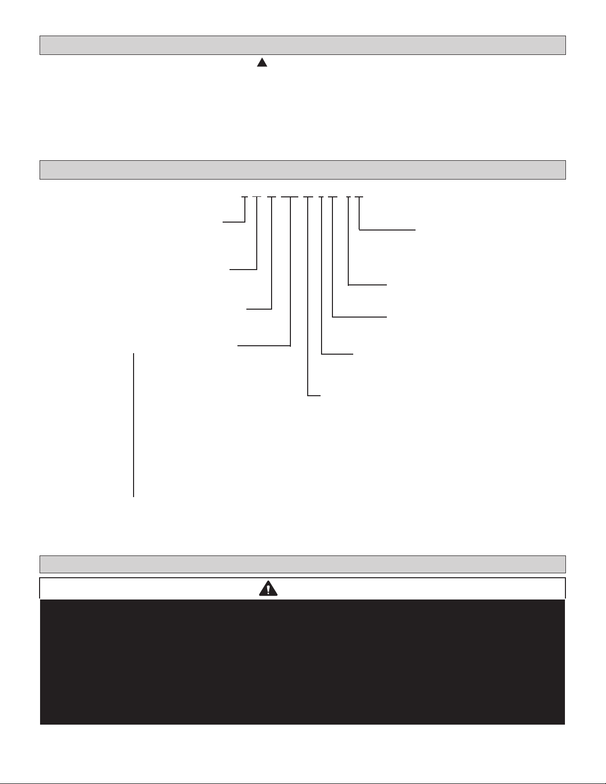
Model Number Identication
V R B 072 H 4 M -3 Y
Brand/Family
V = Variable Refrigerant Flow (VRF)
Unit Type
R = Heat Recovery Outdoor Unit
Major Design Sequence
B = 2nd Generation
Nominal Cooling Capacity - Tons
072 = 6 Tons
096 = 8 Tons
120 = 10 Tons
144 = 12 Tons
168 = 14 Tons
192 = 16 Tons
216 = 18 Tons
240 = 20 Tons
264 = 22 Tons
288 = 24 Tons
312 = 26 Tons
336 = 28 Tons
360 = 30 Tons
384 = 32 Tons
408 = 34 Tons
432 = 36 Tons
456 = 38 Tons
480 = 40 Tons
504 = 41 Tons
Voltage
Y = 208/230V-3 phase-60hz
G = 460V-3 phase-60hz
Controls Protocol
3 = Phase 3
Refrigerant Circuits
M = Multiple Circuits
Refrigerant Type
4 = R-410A
Cooling Eciency
H = High Eciency
NOTE - Lennox VRF and Lennox Mini-Split products are similar in appearance to each other. Refer to the unit’s model
number to determine if the unit is a VRF (V) or Mini-Split (M) unit. It is not possible to mix the two types of equipment
on any system.
System Piping
CAUTION
VRF system piping is customized for each installation. The Lennox VRF Selection Software (LVSS) piping report is an
engineered design that must be followed. The piping diagram or diagrams included within the LVSS report have been
prepared based on the information provided to the Lennox VRF applications department.
When the indicated lengths change from the gures stated within the report, it is imperative that prior to the commencement
of the refrigerant pipe work installation, Lennox VRF applications department are informed of these proposed changes.
Upon receipt of this new information the Lennox VRF applications department will conrm any changes that may be
applicable to this installation. If changes are required, a new piping diagram will be produced and will supersede all other
previously provided documents.
Failure to provide this information regarding changes to the original design may lead to insucient capacity, equipment
failure, warranty being made void and the refusal to commission the system.
2
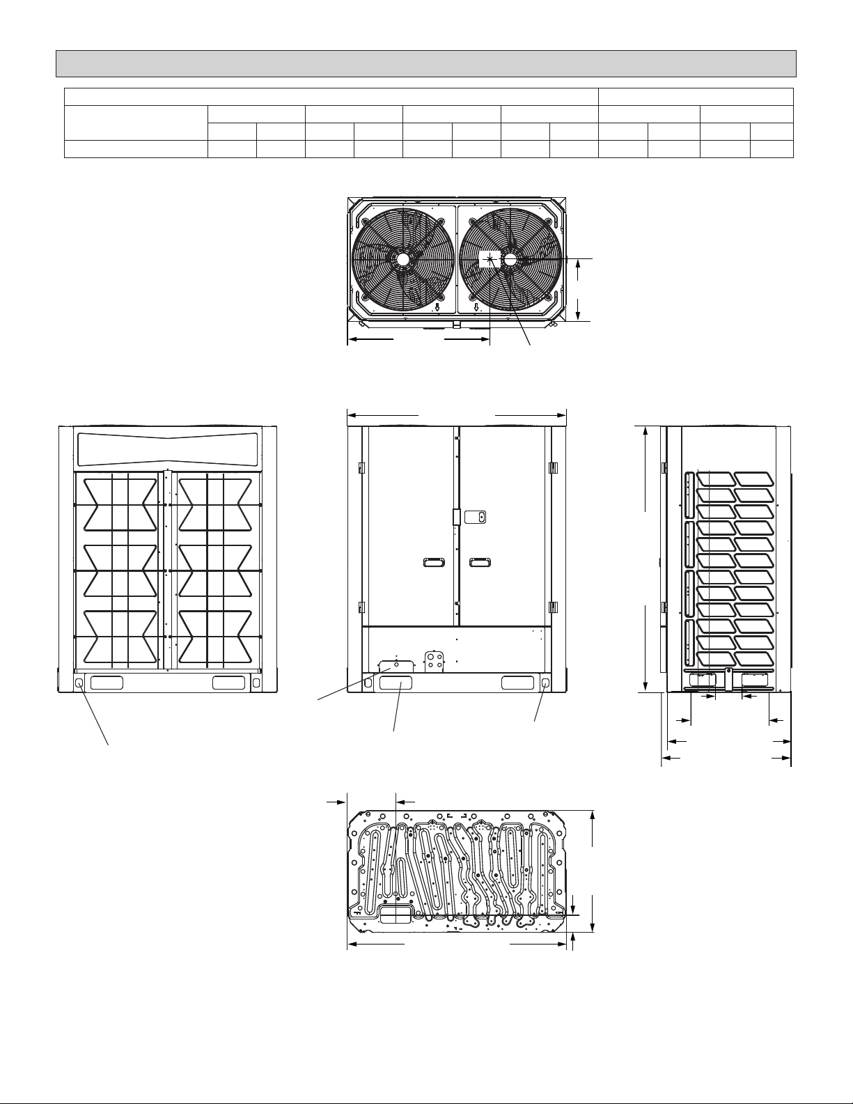
Unit Dimensions - inches (mm)
CORNER WEIGHTS CENTER OF GRAVITY
Model No. AA BB CC DD EE FF
lbs. kg lbs. kg lbs. kg lbs. kg in. mm in. mm
072, 096, 120 121 55 203 92 211 96 251 114 27-3/4 705 12-1/4 311
AA
DD
EE
TOP VIEW
52-3/4 (1340)
BB
FF
CC
CENTER OF
GRAVITY
64-3/8
(1635)
BACK VIEW
LAG BOLT DESIGNATION
(BOTH SIDES)
(TO ACCESS LAG BOLT)
PARALLEL MODULE
PIPING KNOCKOUT
FORKLIFT SLOT
REFRIGERANT LINE PATH
FRONT VIEW
(BOTH SIDES)
11-3/4 (298)
53-1/8 (1349)
BASE PAN VIEW
3
LIFTING HOLES
(BOTH SIDES)
(FOR RIGGING)
6-1/4 (159)
18-7/8 (479)
29-7/8 (759)
31-1/2 (800)
SIDE VIEW
29-1/2
(749)
4-1/8 (105)
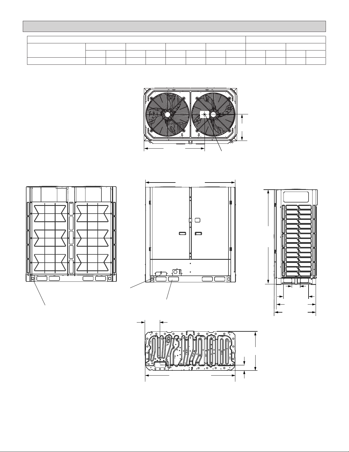
Unit Dimensions - inches (mm)
CORNER WEIGHTS CENTER OF GRAVITY
Model No. AA BB CC DD EE FF
lbs. kg lbs. kg lbs. kg lbs. kg in. mm in. mm
144, 168, 192 172 78 264 120 330 150 321 146 37-3/4 953 12 305
AA
DD
EE
TOP VIEW
68-1/2 (1740)
BB
FF
CC
CENTER OF
GRAVITY
72 (1829)
BACK VIEW
LAG BOLT DESIGNATION
(BOTH SIDES)
(TO ACCESS LAG BOLT)
PARALLEL MODULE
PIPING KNOCKOUT
REFRIGERANT LINE PATH
FRONT VIEW
FORKLIFT SLOT
(BOTH SIDES)
11-3/8 (289)
68-1/2 (1740)
BASE PAN VIEW
4
6-1/4 (159)
18-7/8 (479)
30 (762)
32-5/8 (829)
SIDE VIEW
29-3/4 (756)
4-1/8 (105)
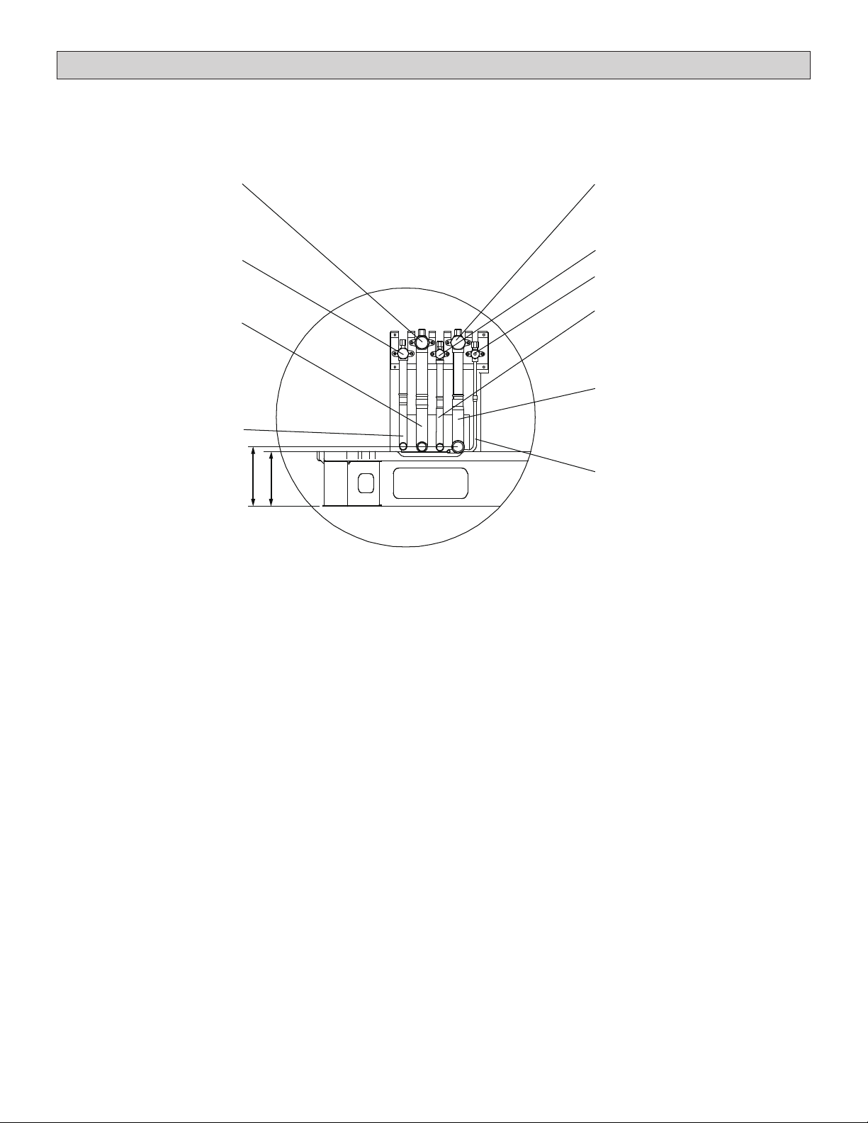
Dimensions - Piping Details - inches (mm)
Internal valve layouts are the same in both heat
recovery and heat pump units, it is their function that
is dierent. Pay close attention when making nal
piping connections.
Low pressure gas valve
High pressure
gas balance valve
Low pressure gas pipe
(1-1/8 in. diameter 072-120 sizes)
(1-3/8 in. diameter 144-192 sizes)
High pressure
gas balance pipe
(3/4 in. diameter)
6-1/4 (159)
5-5/8 (143)
Heat Recovery internal valve layouts are described
below. See the Heat Pump installation manual for
heat pump internal valve information.
High pressure gas valve
Liquid side valve
Liquid side valve
Oil balance valve
Liquid side pipe
(5/8 in. diameter 072-120 sizes)
(3/4 in. diameter 144-192 sizes)
High pressure gas pipe
(1-1/8 in. diameter 072-120 sizes)
(1-3/8 in. diameter 144-192 sizes)
Oil balance pipe
(1/4 in. diameter)
5
Outdoor Unit Placement Considerations
!
WARNING
Use the provided and specied components
when installing equipment. Failure to do so may
result in unit falling, water leaking or electrical
shocks, caus ing personal injury or equipment
or property dam age.
Check stability of unit support. If sup port is
not capable of carrying weight of the unit, unit
may fall causing personal injury or equipment
damage.
Safely dispose of packing materials, which
include nails, wood and other sharp objects,
as well as plastic wrapping. Children playing
with plastic wrap or bags risk the danger of
suocation.
IMPORTANT!
Exhaust vents from dryers, water heaters and
furnaces should be directed away from the
outdoor unit. Prolonged exposure to exhaust
gases and the chemicals contained within
them may cause condensation to form on the
steel cabinet and other metal components of
the outdoor unit. This will diminish unit performance and longevity.
In addition to clearances, the following items should
be considered when setting the outdoor unit:
• 2007 EPA Noise Policy. Observe local code
adoptions/enforcement as consideration should
be used when selecting an outdoor unit’s permanent placement. Sound data for each unit can be
found in the Product Specications Document.
• Glass has a very high level of sound transmission. When possible, do not install the unit directly outside a window.
• Avoid installing the unit in areas exposed to ex-
treme voltage variations (such as factories).
• Install unit level.
• Allow sucient space around unit for proper operation and maintenance.
• Install the outdoor unit a minimum of 3 ft. (1 m)
away from any antenna, power cord (line), radio,
telephone, security system, or intercom. Electri-
cal interference and radio frequencies from any
of these sources may aect operation.
• Outdoor unit shall maintain a minimum distance
of 10 ft. (3 m) from dryer exhaust vents.
• Outdoor unit shall maintain a minimum distance
of 10 ft. (3 m) from Type 1 kitchen exhaust outlets.
• Coating outdoor coils is recommended in applications installed in coastal regions less than 30
miles (48 kilometers) inland.
6

SINGLE ROW
Lifting the Unit
• Do not hold the air inlet grille while lifting the unit.
This could result in damage to the cabinet.
39 (991)
• Do not touch the fan blades with your hands or
other objects while lifting the unit.
Air Flow
Air Flow
31 (800)
39 (991)
39 (991)
Front Front
4 to 20 (102 to 508)
TWO ROWS
39 (991)
39 (991)
Front Front
39 (991)
Front Front
39 (991)
4 to 20 (102 to 508)
THREE OR MORE ROWS
FrontRear
Air Flow
Air Flow
31 (800)
39 (991)
39 (991)
39 (991)
39 (991)
39 (991)
Front Front
Air Flow
Front Front
Air Flow
31 (800)
Front Front
4 to 20 (102 to 508)
Figure 1. Installation Clearances - inches (mm)
7
NOTICE
Drawings in this manual are for illustrative purposes
and should not be used as a template for fabricating
eld-supplied accessories or apparatuses. Consider
the environment in which this unit is being installed and
make necessary adjustments to ensure safe operation.
Local codes prevail.
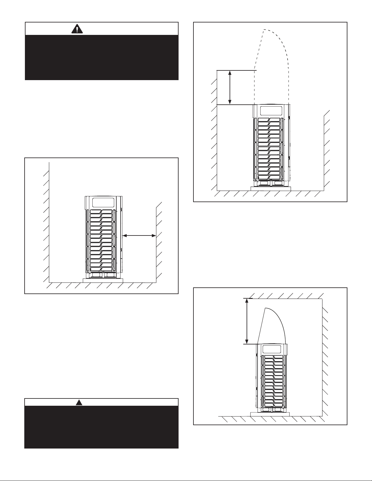
Clearances from Obstructions
• Allow adequate air ow clearance on all sides of
the unit. See Figure 1 and this section.
• Allow at least 39 in. (991 mm) clearance in front
of the unit for maintenance and service access.
The outdoor unit service access is via hinged
service doors that swing open in front of the unit.
Figure 2.
>39”
(991 mm)
Rear Side
Front Side
>32”
(813 mm)
Front SideRear Side
Figure 3. Perimeter Obstructions
• Allow at least 120 in. (3048 mm) clearance above
the unit. If an obstruction above the unit does not
allow for adequate clearance, a eld-supplied
discharge duct is required. The discharge duct
should be installed in such a way as to ensure
that discharge air goes beyond the obstruction
and does not cause recirculation of discharge air.
Ensure that the static capabilities of the outdoor
unit are not exceeded. Figure 4.
Figure 2. Maintenance & Service Clearance
• Perimeter obstructions that are 32 in. (813
mm) taller than the top of the outdoor unit
require a eld supplied air discharge duct
to avoid recirculation of discharge air.
The discharge duct should be installed to at
least the height of the surrounding obstructions
(for ex. walls) to ensure that discharge air
goes over the height of the obstruction.
Ensure that the static capabilities of the outdoor
unit are not exceeded. Figure 3.
!
CAUTION
In order to avoid injury, take proper precaution
when lifting heavy objects.
Take care when using a sling to lift the unit for
in stallation. The unit center of gravity is not at
its physical center.
>120”
(3048 mm)
Front Side Rear Side
Figure 4. Obstructions Above the Unit
8
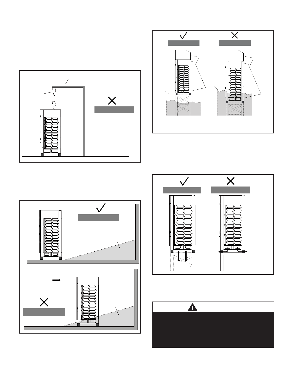
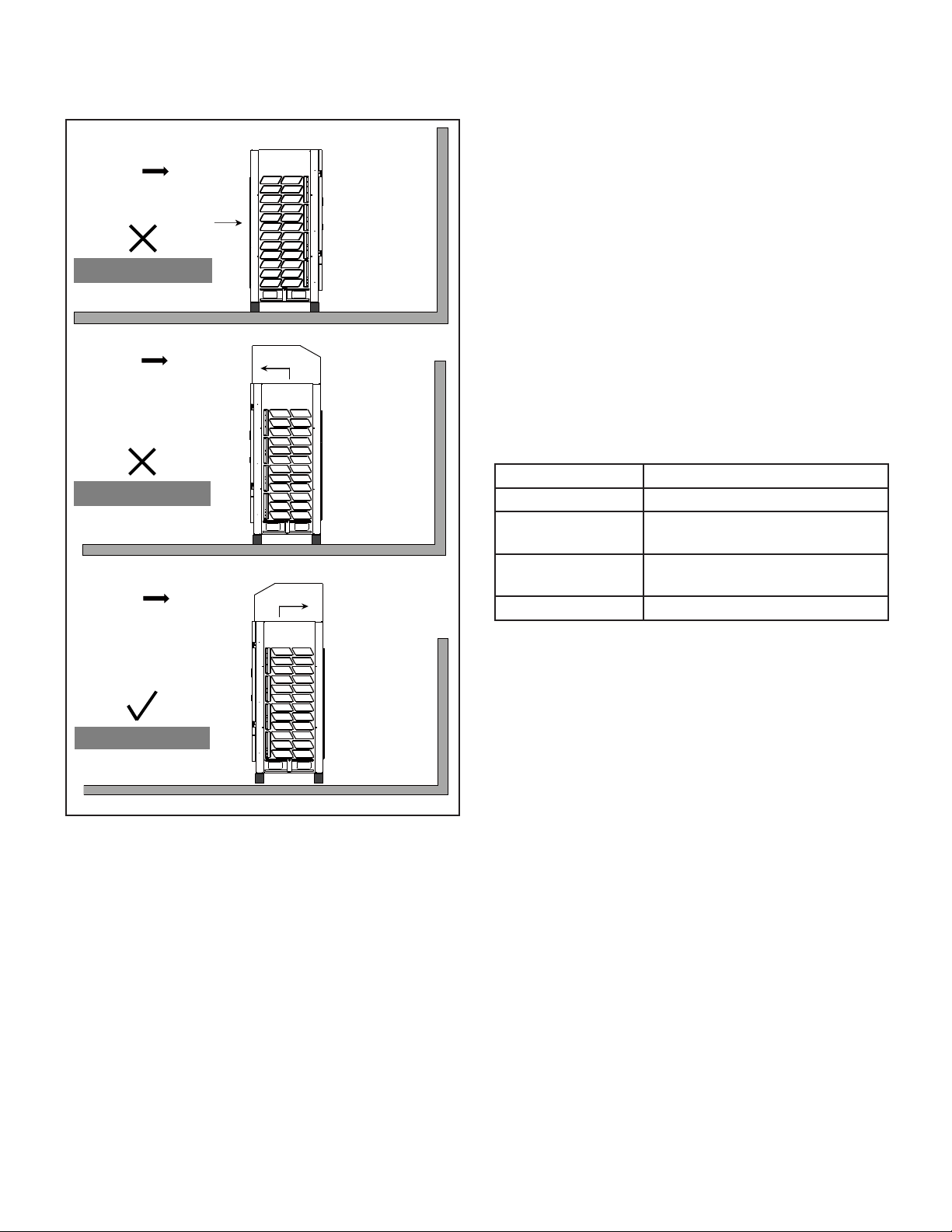
Cold Climate Considerations
Select a location where high winds and snow will not
aect the unit. In areas where typical ambient temperatures are below 50°F (10°C), the following pre-
cautions should be observed.
• Locate unit away from overhanging roof lines
which would allow water or ice to drop on, or in
front of, coil or into unit.
Eaves
Icicle
Wrong Installation
• Install snow guards to prevent snow fall from entering air inlet and outlet.
Correct Installation
Snow
Guard
Kit
Snow level
Wrong Installation
Snow
Guard
Kit
RearFrontRearFront
Snow level
RearFront
Figure 5. Do Not Locate Under Roof Overhang
• The unit base should be elevated above the
depth of average snows plus 12 in. (305 mm). In
heavy snow areas, do not locate the unit where
drifting will occur.
Correct Installation
RearFront
Snow Drifts
NOTE - Snow guards are recommended on both sides
and rear of the unit as shown in this example.
Figure 7. Elevate Above Average Snow Level
& Protect Coil
• If necessary, install the unit on a raised base
made of angle iron and that allows snow and
wind to pass through
Correct Installation
RearFront
Wrong Installation
Defrost
Water
RearFront
Defrost
Water
Wind
RearFront
Snowdrift
Wrong Installation
Figure 6. Do Not Locate Where Drifting Will Occur
Defrost
Water
Figure 8. Secure Unit to
Weather Resistant Support
IMPORTANT
These illustrations are examples of possible snow
protection options. They should not be used as a
template for fabricating the snow protection apparatuses.
Consider the environment in which this unit is being
installed and make necessary adjustments to ensure
safe operation.
9
• When installed in areas where low ambient tem-
peratures exist, locate unit so winter prevailing
winds do not blow directly on to the outdoor unit.
Wind
Rear Front
Wind
Wind
Inlet
Outlet
RearFront
Outlet
llation
Wrong Installation
Wrong Installation
Air Discharge Duct
• Before installing the air duct, remove the two fan
guards from the top of the unit.
• Duct each outdoor unit separately. Do not use
a combined plenum as this may result in air not
being discharged directly to the outside.
• Discharge air duct shall be constructed of steel
and installed in a manner which prevents sagging
and or collapsing.
• Only one bend is allowed in the air duct.
• Duct louvers will reduce air volume, cooling and
heating capacity and eciency. Louvers are not
recommended; if they are required by the job,
the louver angle should be no larger than 15°.
• It may be necessary to install a exible connector
between the unit and the duct to reduce vibration
noise.
Table 1. Static Pressure Settings
Static Pressure Description
0 WG (0 Pa) Default
0-0.08 WG (0-20
Pa)
Above 0.08 WG
(20 Pa)
Remove fan guard, < 10 ft. (3 m)
duct length
Contact Lennox VRF Applications
Support
RearFront
Correct Installation
Figure 9. Protect Unit from Prevailing Winds
NOTE - Use dip switch S4 to change outdoor
unit static pressure settings.
10
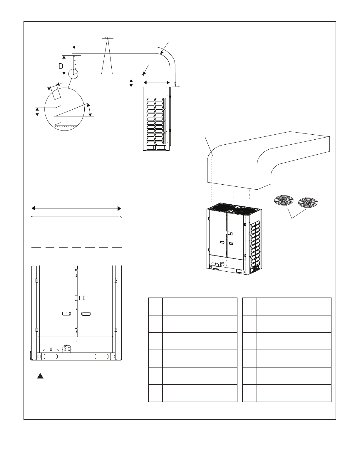
Support
C
Radius
E
A
Radius
3-1/2 in.
(89 mm)
≤ 15°
4 in. (102 mm)
Air Outlet Louver
072, 096, 120 -- 50-3/4 in. (1289 mm)
144, 168, 192 -- 65 in. (1651 mm)
B
F
8 × ST3.9
self-threading screws
Fan guards
(remove
first)
!
Contact the Lennox VRF
applications department for
assistance with ducting applications
that dier from these images.
Figure 10. Air Discharge Duct
072, 096, 120
A A ≥ 12 in.(305 mm)
B B ≥ 10 in. (254 mm)
C C ≤ 118-1/8 in. (3000 mm)
D D ≥ 24 in. (610 mm)
E E = A + 24 in. (610 mm)
F 24 in. (610 mm)
(Front or Rear Connection)
11
144, 168, 192
A A ≥ 12 in.(305 mm)
B B ≥ 10 in. (254 mm)
C C ≤ 118-1/8 in. (3000 mm)
D D ≥ 28-3/8 in. (721 mm)
E E = A + 24 in. (610 mm)
F 28-3/8 in. (721 mm)
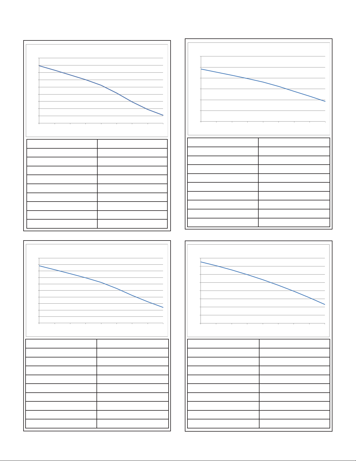
Discharge Duct Pressure Curves
VRB072
VRB120
6-ton Air Volume (CFM)
15000
14000
13000
12000
11000
10000
9000
8000
7000
6000
0 0.04 0.08 0.1 2 0.16 0.2 0.24 0.2 8 0.32
Static Pressure (in.wg.) Air Volume (CFM)
0 13934
0.04 13320
0.08 12667
0.12 12010
0.16 11236
0.2 10163
0.24 8940
0.28 7902
0.32 7094
10-ton Air Volume (CFM)
18000
16000
14000
12000
10000
8000
6000
0 0.04 0.08 0.12 0.16 0.2 0.24 0.28 0.32
Static Pressure (in.wg.) Air Volume (CFM)
0 15667
0.04 15090
0.08 14508
0.12 13907
0.16 13261
0.2 12467
0.24 11554
0.28 10655
0.32 9709
VRB096
8-ton Air Volume (CFM)
16000
15000
14000
13000
12000
11000
10000
9000
8000
7000
6000
0 0.04 0.08 0.12 0.16 0.2 0.24 0.28 0.32
Static Pressure (in.wg.) Air Volume (CFM)
0 14800
0.04 14205
0.08 13587
0.12 12958
0.16 12248
0.2 11315
0.24 10247
0.28 9279
0.32 8402
VRB144, 168, & 192
12~16-ton Air Volume (CFM)
25000
24000
23000
22000
21000
20000
19000
18000
17000
0 0.04 0.08 0.12 0.16 0.2 0.24 0.28 0.32
Static Pressure (in.wg.) Air Volume (CFM)
0 24544
0.04 24079
0.08 23559
0.12 22986
0.16 22360
0.2 21679
0.24 20945
0.28 20157
0.32 19315
12
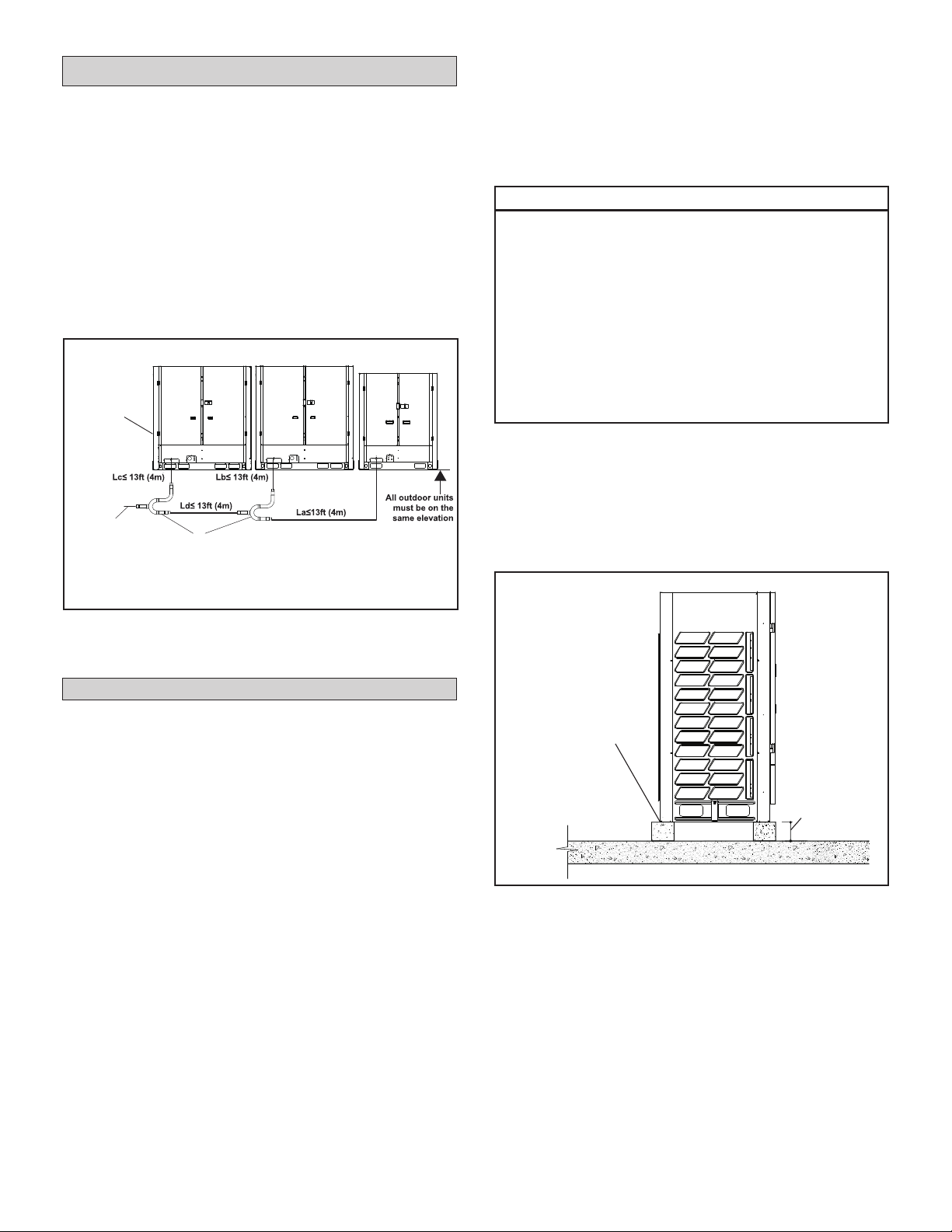
Main/Sub Outdoor Unit Placement
• A VRF system consisting of more than two
outdoor units must be placed in order from the
largest to the smallest capacity. See gure 8.
• The largest capacity outdoor unit must be
installed closest to the main pipe leading into the
building. See Figure 11.
• The largest capacity outdoor unit address is the
main unit, while the others are the sub units. See
Figure 11.
• All of the outdoor units manifolded together
should be installed at the same elevation.
Main unit
placed
closest to
main pipe
leading into
building
Main piping
to building
16-ton
Outdoor Unit
Branch Pipe Kits
14-ton 10-ton
NOTE - All of the outdoor units manifolded
together should be installed at the same elevation.
• If the unit coil cannot be installed away from
prevailing winter winds, a wind barrier should
be constructed. Size barrier at least the same
height and width as outdoor unit. Install barrier
12 inches (305 mm) minimum from the sides of
the unit in the direction of prevailing winds.
IMPORTANT!
Roof Damage!
This system contains both refrigerant and
oil. Some rubber roong material may absorb
oil. This will cause the rubber to swell when
it comes into contact with oil. The rubber will
then bubble and could cause leaks. Protect the
roof surface to avoid expo sure to refrigerant
and oil during service and instal lation. Failure
to follow this notice could result in damage to
roof surface.
Securing Outdoor Unit to Slab or Frame
Use lag bolts (min. 3/8 in.) at all four corners to
secure the unit to the eld-provided slab or frame.
Isolation material can be used to control vibration or
sound transmission. Lag bolts must extend through
material to the slab or frame. See Figure 12.
Figure 11. Main/Sub Unit Placement
(40-Ton System Example)
Installation
Slab or Roof Mounting
Install the unit a minimum of 8 inches (203 mm)
above the roof or ground surface to avoid ice buildup around the unit. Locate the unit above a loadbearing area of the roof that can adequately support
the unit. Consult local codes for rooftop applications.
• Use a eld supplied slab or suitably sized
steelwork to construct a base for locating
the condensing unit. All supporting work
should be veried by a qualied engineer.
NOTE - Prefabricated light duty equipment pads
are NOT suitable for use.
• Support the unit across the front and back of the
unit.
Use lag
bolts (4) to
secure unit
to slab or
approved frame
at each corner
8 in.
(203 mm)
Figure 12. Secure Outdoor Unit
to Approved Structure
13
Refrigerant Piping Connections
!
WARNING
Refrigerant leaks are unlikely; however, if a
refriger ant leak occurs, open a door or windows
to dilute the refrigerant in the room. Turn o the
unit and all other appliances that may cause
a spark. Call a li censed professional HVAC
technician (or equiva lent) to repair the leak.
Use only R-410A refrigerant to charge this
system. Use of other refrigerant or gas will
damage the equipment.
Do not allow air or other contaminants to
enter sys tem during installation of refrigerant
piping. Con taminants will result in lower
system capacity and abnormally high operating
pressures and may res ult in system failure or
explosion.
Insulate all refrigerant piping.
Refrigerant pipes may be very hot during unit
opera tion. Do not allow contact between wiring
and bare copper pipes.
After refrigerant piping connections have been
completed, check the system for leaks per
commis sioning instructions.
• Both liquid and gas (vapor) lines must be indi-
vidually insulated.
• Field piping consists of three HVAC/R eld-pro-
vided copper refrigerant lines connected to the
outdoor unit. These lines carry the liquid and vapor refrigerant to and from the mode selection
box(es).
• Refrigerant piping and wiring connections can be
brought into the outdoor unit through openings
provided in the front, side(s), or underside (recommended) of the unit.
• Refrigerant piping must be connected using
mode selection boxes and individual branch pipe
kits. Six mode selection boxes are available in
varying sizes to accommodate connection of one
to 41 indoor units.
• The following restrictions apply to each VRB system:
• Total refrigerant pipe length 3280 ft. (1000 m)
• Longest pipe length actual) 574 ft. (175 m)
• Level dierence between indoor units 98 ft.
(30 m)
• Piping length from the rst branch pipe to the
farthest indoor unit 132/295 ft. (40/90 m)
• For each branch pipe, allow 20” (508 mm) of
equivalent length.
!
Contact the Lennox VRF applications department
for assistance.
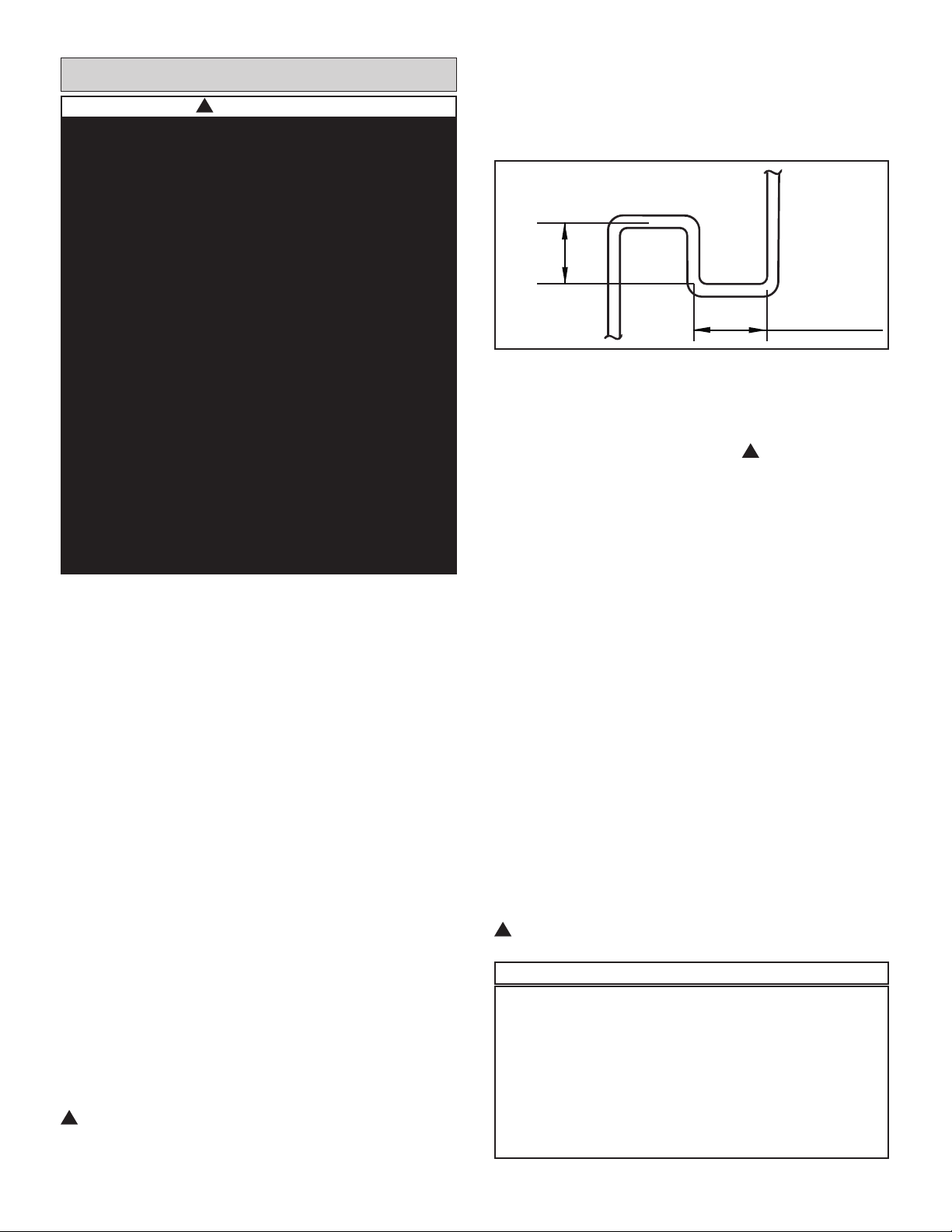
• When the outdoor unit is installed 164 feet (50
m) or more above the indoor units, install an oil
return trap every 33 feet (10 m) in the main low
pressure gas pipe. See Figure 13 for trap speci-
cations.
≥1ft
≥1ft
Figure 13. Oil Return Trap
• When the outdoor unit is 132 feet (40 m) or more
below the indoor units, increase the diameter of
the liquid line pipe from the outdoor unit to the
rst branch pipe by one size. ! Contact the Lennox VRF applications department for assistance.
• To extend the length from the rst branch pipe to
the farthest indoor unit beyond 132 ft. (40 m) and
up to 295 ft. (90 m), the following three conditions
must be met.
1. Increase diameter of the main pipe between
the rst and the last branch pipes. If the diameter of the pipe is the same as the main outdoor
pipe, then it does not need to be increased.
Ex: If 132 ft.<L1+L7+L9+L10 ≤ 295 ft., in-
crease the diameter of all the pipes by one
size.
2. The length from the indoor unit to the nearest
branch pipe must be 132 ft. (40 m) or less.
Ex: a,b,c,d,e,f,g,h,i,j,k,l,m ≤ 132 ft.
3. The dierence between [the distance from
the outdoor unit to the farthest indoor
unit] and [the distance from the outdoor
unit to the nearest indoor unit] is ≤132 ft.
Ex:(L1+L7+L9+L11+11+j+k+n)
-(L1+L7+L8+p)
≤ 132 ft.
!
Contact the Lennox VRF applications department
for assistance.
IMPORTANT!
The compressor in this unit contains PVE oil
(Polyvinylether). PVE oil is formulated for hy-
drouorocarbon (HFC) refrigerants, such as R-
410a, which this system contains. While it may
have some miscibility properties with mineral
based oil and POE oil (Polyolester), you should
not mix PVE oil with any other type of refrigerant oil.
14

Maximum Permitted Refrigerant Pipe Length and Maximum Height Difference
OUTDOOR UNITS
(one or more outdoor units)
NOTE - Capacities are shown in parenthesis
a
b
c
MS1
L1
A
L2
L3
B
L4
C
L6
L5
MS3
MS2
INDOOR UNITS
N1
(024)
N2
(024)
d
e
The first line Branch Pipe
N4
(009)
N3
(048)
Maximum equivalent single piping length - 656 ft.(200 m)
L7
Maximum piping length from the first Branch Pipe
joint to the farthest indoor unit - 295 ft. (90 m)
LEGEND
Branch Pipe
Mode Selection
Box (MS)
Maximum level difference between
Indoor Unit
L8
D
L9
L10
E
L11
F
MS6
Indoor Unit and Outdoor Unit - 361 ft. (110 m)
MS7
f
MS4
L12
MS5
L13
Maximum piping length from MS Device
to downstream indoor unit - 131 ft. (40 m)
k
j
r
N13
(018)
q
N12
(048)
p
N11
(048)
l
N5
(048)
g
i
m n
N8
(009)
h
N9
(018)
N6
(024)
N7
(024)
N10
(018)
Maximum level difference between indoor units - 98 ft. (30 m)
Piping Length Permitted value Piping
Total piping length
Single piping length
Piping length from the rst branch joint to the
Piping
Length
farthest indoor unit
Actual length 574 ft. (175 m)
Equivalent length2 656 ft. (200 m)
Piping length from Mode Selection Box (MS) to
the downstream indoor unit of itself
Level dierence between
indoor unit and outdoor unit
Level
Level dierence between indoor units 98 ft. (30 m) - - -
Dierence
NOTES:
The rst branch in all systems must be centrally located between all Mode Selection (MS) Boxes.
1
When counting the total piping length, double the actual length of the distribution pipes between rst Branch Pipe joint and Mode Selection Box (MS): Installation.
Total piping length = L1+(L2+L3+L4+L5+L6+L7+L8+L9+L10+L11+L12+L13)×2+a+b+c+d+e+f+g+h+i+j+k+l+m+n+p+q+r ≤ 3280 ft.(1000 m).
2
Each Branch Pipe or bend is equivalent to 20 in. (508 mm).
3
The maximum allowable piping length from the rst Branch Pipe joint to the farthest indoor unit must be ≤ 132 ft. (40 m), but if the following conditions are met, the
maximum allowable length can be extended to 295 ft. (90 m):
• The piping length from each indoor unit to the nearest Branch Pipe joint or direct connected Mode Selection Box (MS) must be less than 132 ft. (40m) (b to r).
• The dierence in length between the outdoor unit to the farthest indoor unit, and the outdoor unit to the nearest indoor unit is ≤ 132 ft. (40 m).
Example: The farthest indoor unit is N10, The nearest indoor unit is N11 (L1+L7+L9+L11+j+k+n) minus (L1+L7+L8+p) ≤ 132 ft. (40 m).
• Increase the distribution pipe diameter between the rst Branch Pipe and Mode Selection Box (MS) L2-L13. If the pipe diameter is the same as the main outdoor pipe,
it does not need to be increased.
Pipe Size Allowable Increase Diameters (in.):
3/8 to 1/2 1/2 to 5/8 5/8 to 3/4 3/4 to 7/8 7/8 to 1-1/8 1-1/8 to 1-3/8 1-3/8 to 1-5/8 1-5/8 to 2-1/8
4
When the outdoor unit is higher than indoor units and the level dierence is over 164 ft. (50 m), it is required to set an oil return bend every 33 ft.(10 m) in the gas pipe of
the main pipe. Refer to Installation Instructions for additional details.
5
When the outdoor unit is lower than indoor units and the level dierence is more than 132 ft.(40 m), the main liquid pipe pipe need to increase by one size.
Outdoor unit up4 360 ft. (110 m) - - -
Outdoor unit down
1
3280 ft. (1000 m)
3
132/295 ft. (40/90 m) L7+L9+L11+j+k+n
132 ft. (40 m) j+k+n
5
230 ft. (70 m) - - -
L1+(L2+L3+L4+L5+L6+L7+L8+L9+L10+L11+L12+L1
3)×2+a+b+c+d+e+f+g+h+i+j+k+l+m+n+p+q+r
L1+L7+L9+L11+j+k+n
15
 Loading...