

Page 1

INSTALLATION
E2011 Lennox Industries Inc.
Dallas, Texas, USA
NOTICE
A thermostat is not included and must be ordered
separately.
D The Lennox icomfort Touch thermostat must be used
in communicating applications.
D In non−communicating applications, the Lennox
ComfortSense
as other non−communicating thermostats.
In all cases, setup is critical to ensure proper system
operation.
Field wiring for both communicating and non−
communicating applications is illustrated in diagrams,
which begin on page 13.
®
7000 thermostat may be used, as well
WARNING
Improper installation, adjustment, alteration, service or
maintenance can cause personal injury, loss of life, or
damage to property.
Installation and service must be performed by a licensed
professional installer (or equivalent) or a service agency.
Shipping and Packing List
Check unit for shipping damage. Consult last carrier
immediately if damage is found.
Package 1 of 1 contains the following:
1 Assembled air handler unit
2 Downflow shields (if required for downflow
configuration only)
1 Drip shield (for −068 only)
INSTRUCTIONS
Dave Lennox Signature
Collection CBX32MV Units
MULTI−POSITION AIR HANDLER
506274−01
06/11
Supersedes 01/11
RETAIN THESE INSTRUCTIONS FOR FUTURE
REFERENCE
Table of Contents
Shipping and Packing List 1. . . . . . . . . . . . . . . . . . . . . .
Upflow/Downflow Unit Dimensions 2. . . . . . . . . . . . . .
Horizontal LH/RH Unit Dimensions 3. . . . . . . . . . . . . .
Model Number Identification 4. . . . . . . . . . . . . . . . . . . .
General 4. . . . . . . . . . . . . . . . . . . . . . . . . . . . . . . . . . . . . .
Installation Clearances 4. . . . . . . . . . . . . . . . . . . . . . . . .
Requirements 5. . . . . . . . . . . . . . . . . . . . . . . . . . . . . . . . .
Installing the Unit 5. . . . . . . . . . . . . . . . . . . . . . . . . . . . . .
Brazing Connections 9. . . . . . . . . . . . . . . . . . . . . . . . . . .
Installing the Condensate Drain 11. . . . . . . . . . . . . . . . .
Inspecting and Replacing Filters 12. . . . . . . . . . . . . . . . .
Sealing the Unit 12. . . . . . . . . . . . . . . . . . . . . . . . . . . . . . .
Field Control Wiring 13. . . . . . . . . . . . . . . . . . . . . . . . . . . .
Air Handler Control Button, Display and Jumpers 21. .
Target CFM Tables 25. . . . . . . . . . . . . . . . . . . . . . . . . . . .
Configuring Unit 28. . . . . . . . . . . . . . . . . . . . . . . . . . . . . . .
Error Code Recall Mode 35. . . . . . . . . . . . . . . . . . . . . . . .
Indoor Blower Test 36. . . . . . . . . . . . . . . . . . . . . . . . . . . . .
Checkout Procedures 36. . . . . . . . . . . . . . . . . . . . . . . . . .
Operation 37. . . . . . . . . . . . . . . . . . . . . . . . . . . . . . . . . . . .
Maintenance 37. . . . . . . . . . . . . . . . . . . . . . . . . . . . . . . . . .
Cabinet Insulation 37. . . . . . . . . . . . . . . . . . . . . . . . . . . . .
®
Litho U.S.A.
IMPORTANT INFORMATION TO INSTALLER
CHECK FOR AND REMOVE THE FOLLOWING ITEMS BEFORE OPERATING UNIT.
BLOWER HOUSING SUPPORT PAD.
A
REFRIGERANT LINE PLUGS (SEE BRAZING CONNECTION
D
ON PAGE 9] .
FOR PROPER OPERATION THE ELECTRIC HEAT (IF APPLICABLE) MUST BE
CONFIGURED (SET−UP) THROUGH THE AIR HANDLER CONTROL (AHC)
WHENEVER ELECTRIC HEAT IS INSTALLED THE AHC MUST BE
MANUALLY CONFIGURED. SEE JUMPERS AND LINKS GUIDE ON
PAGE 20.
H
06/11 506274−01
TOP CAP SHIPPING BRACKET (REPLACE
B
SCREWS IN TOP CAP AFTER REMOVAL).
CONFIGURE ELECTRIC HEAT
ELECTRIC HEAT SECTIONS MUST BE
CONFIGURED. IF INSTALLED SEE
H
PROCEDURE IN FIGURE 24 ON PAGE 30.
*2P0611* *P506274-01*
Page 1
HORIZONTAL DRAIN PAN (SEE
C
UPFLOW APPLICATIONS ON PAGE
5 AND DOWNFLOW APPLICATIONS
ON PAGE 8 )
ECB40
Page 2

Upflow and Downflow Unit Dimensions Inches (millimeters)
3/4 (19)
SUPPLY AIR
OPENING
D
11-1/16 (281)
LINE VOLTAGE
INLETS (TOP
AND LEFT SIDE)
TOP VIEW
3/4 (19)
LOW VOLTAGE
INLETS (TOP AND
RIGHT SIDE)
5/8 (16)
BC
AIR
FLOW
G
OPTIONAL
ELECTRIC HEAT
(FIELD−INSTALLED)
A
SUCTION
H
RETURN AIR
5/8 (16) 1 (25)
KNOCKOUT FOR OPTIONAL HEALTHY
F
CLIMATE® GERMICIDAL UVC LIGHT.
FRONT VIEW
FILTER ACCESS
5/8 (16)
UPFLOW POSITION
LINE
LIQUID
LINE
FILTER
2
COIL
E
2-3/4
(70)
5/8 (16)
PIPING PLATE DETAIL
1-3/4 (44)
FILTER
SUCTION
LINE
LIQUID
LINE
OPTIONAL
ELECTRIC HEAT
(FIELD−INSTALLED)
LOW VOLTAGE
(RIGHT SIDE)
LINE VOLTAGE
(LEFT SIDE)
4-3/8 (111)
SUCTION LINE
CONDENSATE DRAINS
(2) (HORIZONTAL)
LIQUID LINE
CONDENSATE DRAINS
(2) (UPFLOW AND
DOWNFLOW)
3-1/2 (89)
11-1/16 (281)
(FOR UPFLOW AND DOWNFLOW POSITIONS)
1-1/8 (29)
(51)
5-3/8
(137)
BLOWER
RETURN AIR
SIDE VIEW
5/8 (16)
C
COIL
BLOWER
SUPPLY
AIR
5/8 (16)
KNOCKOUT FOR OPTIONAL HEALTHY
CLIMATE® GERMICIDAL UVC LIGHT.
SIDE VIEW
DOWNFLOW POSITION
5/8 (16)
5/8 (16)
F
RETURN
E
OPENING
1 (25)
TOP VIEW
B
AIR FLOW
SUPPLY AIR
D
FRONT VIEW
5/8 (16)
AIR
FILTER ACCESS
H
A
G
5/8 (16)
Dim.
A
B
C
D
E
F
G
H
Model Dimensions (Upflow, Downflow, Left− and Right−Hand Horizontal applications)
−018/024 −024/030 −036 −048 and −060 −068
in. (mm) in. (mm) in. (mm) in. (mm) in. (mm)
45−1/4 (1149) 49−1/4 (1251) 51 (1295) 58-1/2 (1486) 65 (1651)
16−1/4 (413) 21−1/4 (540) 21-1/4 (540) 21-1/4 (540) 21−1/4 (540)
20−5/8 (524) 20−5/8 (524) 22-5/8 (575) 24-5/8 (625) 26−5/8 (676)
14−3/4 (375) 19−3/4 (502) 19-3/4 (502) 19-3/4 (502) 19−3/4 (502)
19 (483) 19 (483) 21 (533) 23 (584) 25 (635)
15 (381) 20 (508) 20 (508) 20 (508) 20 (508)
24−5/8 (625) 24−5/8 (625) 26-3/8 (670) 27-7/8 (708) 32−3/8 (822)
20−5/8 (524) 24−5/8 (625) 24-5/8 (625) 30-5/8 (778) 32−5/8 (829)
Page 2
Page 3

Horizontal Left− and Right−Hand Unit Dimensions Inches (mm)
5-3/8
(137)
CONDENSATE
DRAINS (2)
(UPFLOW AND
DOWNFLOW)
CONDENSATE
DRAINS (2)
(HORIZONTAL)
PIPING PLATE
DETAIL
5/8 (16)
5/8 (16)
5/8 (16)
5-3/4
(46)
E
RETURN AIR
OPENING
F
END VIEW
Horizontal Position
(Left-Hand Air
Discharge)
1-3/4
(44)
(51)
2
1-1/2
(38)
1 (25)
FILTER ACCESS
LIQUID
LINE
SUCTION
LINE
1-1/8
(29)
4-3/8
(111)
FILTER
Horizontal Position
(Right-Hand Air
Discharge)
COIL
LIQUID
SUCTION
LINE
LINE
TOP VIEW
A
H
AIR
FLOW
FRONT VIEW
C
BLOWER
BLOWER
OPTIONAL ELECTRIC
HEAT (FIELD−INSTALLED)
G
COIL
5/8 (16)
B
INLETS (BOTTOM
C
LINE VOLTAGE
INLETS (TOP
AND RIGHT
SIDE)
LOW VOLTAGE
AND RIGHT
SIDE)
FOR DIMENSIONS A" THROUGH
H", SEE CHART ON PAGE 2.
11-1/16
3/4 (19)
(281)
SUPPLY
4-3/8
(111)
1-1/8
(29)
AIR
OPENING
END VIEW
D
3/4 (19)
3/4 (19)
3/4 (19)
3/4 (19)
LOW VOLTAGE
3/4 (19)
11-1/16
(281)
SUPPLY
D
OPENING
LINE VOLTAGE INLETS
(BOTTOM AND LEFT SIDE)
END VIEW
INLETS (TOP AND
AIR
LEFT SIDE)
OPTIONAL ELECTRIC
HEAT (FIELD INSTALLED)
5/8 (16)
B
CONDENSATE DRAINS (2)
(HORIZONTAL)
G
A
AIR
FLOW
FRONT VIEW
FILTER
TOP VIEW
SUCTION
LINE
H
1-3/4
(44)
LIQUID
LINE
5-3/4
(146)
SUCTION LINE
PIPING PLATE
DETAIL
FILTER ACCESS
1-1/2 (38)
LIQUID
LINE
1 (25)
(51)
E
RETURN
AIR OPENING
END VIEW
2
5-3/8
(137)
5/8 (16)
5/8 (16)
F
5/8 (16)
Page 3
CBX32MV SERIES
Page 4

Model Number Identification
Unit Type
CB = Air Handler
Refrigerant Type
X = R410A
Series
Configuration
MV = Multi−Position, Variable
speed blower motor
Nominal Cooling Capacity
018/024 = 1.5 to 2 tons (5.3 to 7 kW)
024/030 = 2 to 2.5 tons (7 to 8.8 kW)
036 = 3 tons (10.6 kW)
048 = 4 tons (14.1 kW)
060 = 5 tons (17.6 kW)
230
CB 32 036−01
MV
−X
−−6
Minor Revision Number
Refrigerant Metering Device
2 = Fixed Orifice
3 = TXV − Bleed port (indoor unit)
4 = TXV − Non−bleed port (indoor unit)
5 = TXV − Non−bleed port (outdoor unit)
6 = TXV − R410A Non−bleed port (indoor
unit)
Voltage
230 = 208/230V−60hz−1ph
General
This indoor unit is designed for installation with optional
field−installed electric heat and a matched remote outdoor
unit that is charged with HFC−410A refrigerant. These
units, designed for indoor installation in multiple positions,
are completely assembled for upflow and horizontal
right−hand discharge before being shipped from the
factory.
All CBX32MV air handlers are equipped with a
factory−installed, internally mounted check / expansion
valve (CTXV), which is suitable for use in HFC−410A
applications.
This air handler is compatible with the ComfortSense® 7000
non−communicating thermostat and non−communicating
outdoor units. In addition, this unit has the enhance capability
of communicating with the icomfort Touch® thermostat and
compatible outdoor units using the Lennox RSBus protocols.
NOTE For downflow or horizontal left−hand air
discharge, certain field modifications are required.
These instructions are intended as a general guide and do
not supersede local or national codes in any way. Consult
authorities having jurisdiction before installation. Check
equipment for shipping damage; if found, immediately
report damage to the last carrier.
IMPORTANT
The Clean Air Act of 1990 bans the intentional venting of
refrigerant (CFCs, HCFCs and HFCs) as of July 1, 1992.
Approved methods of recovery, recycling or reclaiming
must be followed. Fines and/or incarceration may be
levied for noncompliance.
WARNING
During blower operation, the ECM motor emits energy
that may interfere with pacemaker operation.
Interference is reduced by both the sheet metal cabinet
and distance.
CAUTION
Physical contact with metal edges and corners while
applying excessive force or rapid motion can result in
personal injury. Be aware of, and use caution when
working near these areas during installation or while
servicing this equipment.
Installation Clearances
Cabinet 0 inch (0 mm)
To Plenum 1 inch (25 mm)
To Outlet Duct within 3 feet (914
mm)
Floor See Note #1
Service / Maintenance See Note #2
1
Units installed on combustible floors in the down−flow position with
electric heat require optional down−flow additive base.
2 Front service access − 24 inches (610mm) minimum.
NOTE If cabinet depth is more than 24 inches (610
mm), allow a minimum of the cabinet depth plus 2 inches
(51 mm).
1 inch (25 mm)
WARNING
Product contains fiberglass wool.
Disturbing the insulation in this product during installation, maintenance, or repair will expose you to fiberglass
wool. Breathing this may cause lung cancer. (Fiberglass
wool is known to the State of California to cause cancer.)
Fiberglass wool may also cause respiratory, skin, and
eye irritation.
To reduce exposure to this substance or for further information, consult material safety data sheets available
from address shown below, or contact your supervisor.
Lennox Industries Inc.
P.O. Box 799900
Dallas, TX 75379−9900
Page 4
Page 5

WARNING
Improper installation of the air handler can result in
personal injury or death.
Do not allow external combustion products or other
contaminants to enter the return air system or to be
mixed with air that will be supplied to the living space.
Use sheet metal screws and joint tape or duct mastic to
seal return air system to air handler. In platform
installations, the air handler should be sealed airtight to
the return air plenum. A door must never be used as a
portion of the return air duct system. The base must
provide a stable support and an airtight seal to the air
handler. Allow absolutely no sagging, cracks, gaps. etc.
For no reason should return and supply air duct systems
ever be connected to or from other heating devices such
as a fireplace or stove. etc. Fire, explosion, carbon
monoxide poisoning, personal injury and/or property
damage could result.
3. Replace blower and coil assemblies.
4. Replace access panel.
UPFLOW APPLICATION
Use the following procedures to configure the unit for
upflow operations:
HORIZONTAL DRAIN
PAN (MUST BE
REMOVED)
UPFLOW/
DOWNFLOW
DRAIN PAN
Requirements
In addition to conforming to manufacturer’s installation
instructions and local municipal building codes, installation
of Lennox air handler units (with or without optional electric
heat), MUST conform with the following National Fire
Protection Association (NFPA) standards:
S NFPA No. 90A Standard for Installation of Air
Conditioning and Ventilation Systems
S NFPA No. 90B Standard for Installation of
Residence Type Warm Air Heating and Air
Conditioning Systems
This unit is approved for installation clearance to
combustible material as stated on the unit rating plate.
Accessibility and service clearances must take
precedence over combustible material clearances.
Installing the Unit
CBX32MV units are factory−configured for upflow and
horizontal right−hand discharge installation. For downflow or
horizontal left−hand discharge, certain field modifications are
required.
DISASSEMBLE AND REASSEMBLE AIR HANDLER
UNIT
This unit consists of two sections which are shipped
assembled from the factory. If necessary, the unit may be
disassembled to facilitate setting the unit. Follow the steps
below:
To disassemble:
1. Remove access panels.
2. Remove both blower and coil assemblies. This will
lighten the cabinet for lifting.
3. Remove one screw from the left and right posts inside
the unit. Remove one screw from each side on the
back of the unit. Unit sections will now separate.
To reassemble:
1. Align cabinet sections together.
2. Reinstall screws.
Figure 1. Upflow Configuration
Note (−068 model Only) Remove access panels and
the horizontal drip shield along with the corrugated padding
between the blower and coil assembly before operation.
Discard drip shields from the foam pads on top of the unit.
Shields are used for downflow applications only.
1. The horizontal drain pan must be removed when the
coil blower is installed in the upflow position. Removing
horizontal drain pain will allow proper airflow and
increase efficiency.
2. After removing horizontal drain pan, place the unit in
desired location. Set unit so that it is level. Connect
return and supply air plenums as required using sheet
metal screws as illustrated in figure 1.
3. Install units that have no return air plenum on a stand
that is at least 14" from the floor to allow for proper air
return. Lennox offers an optional upflow unit stand as
listed in table 1.
Table 1. Optional Unit Side Stand (Upflow Only)
Models Kit Numbers
−018/024 45K31
−024/030, −036, −048 and −060
45K32
HORIZONTAL RIGHT HAND DISCHARGE
APPLICATION
NOTE When air handler is located above a finished
space, the secondary drain pan must have a larger
footprint than the air handler. In addition, a 3/4" (19.1MM)
overflow drain line must be:
S Connected to secondary drain pan
or
S Connected to the overflow drain outlet of the air
handler drain pan.
Use the following procedures to configure the unit for
horizontal right−hand discharge operations:
NOTE For horizontal applications, a secondary drain
pan is recommended. Refer to local codes.
Page 5
CBX32MV SERIES
Page 6

NOTE (−068 Model Only) Before operating the unit,
remove access panels and the horizontal drip shield and
the corrugated padding between the blower and coil
assembly. Discard the corrugated padding and the
downflow drip shields from the foam pads on top of the unit.
NOTE (−068 Model Only) Install the horizontal shield on
the front edge of the horizontal drain pan as illustrated in
figure 2.
1. No further adjustment is necessary. Set unit so that it is
sloped 1/4 inch (6.35mm) towards the drain pan end of
the unit.
UP−LOAD / DOWNFLOW
DRAIN PAN
HORIZONTAL DRIP SHIELD (−068
MODELS)
2. Remove the downflow rail then replace screws.
3. Seal around the exiting drain pipe, liquid line, and
suction line to prevent humid air from infiltrating into
the unit.
IMPORTANT
When removing the coil, there is possible danger of
equipment damage and personal injury. Be careful when
removing the coil assembly from a unit installed in right−
or left−hand applications. The coil may tip into the drain
pan once it is clear of the cabinet. Support the coil when
removing it.
1/2 IN. SCREWS MAXIMUM
ANGLE IRON OR
SHEET METAL
ELECTRICAL INLET
CLEARANCE 4 IN. (102 MM)
HORIZONTAL DRAIN
PAN
NO ADJUSTMENT IS NECESSARY
DOWNFLOW RAIL
Figure 2. Right−Hand Discharge Configuration
2. If the unit is suspended, the entire length of the cabinet
must be supported. If you use a chain or strap, use a
piece of angle iron or sheet metal attached to the unit
(either above or below) to support the length of the
cabinet. Use securing screws no longer than 1/2 inch
(12.7mm) to avoid damaging the coil or filter as
illustrated in figure 3. Use sheet metal screws to
connect the return and supply air plenums as required.
HORIZONTAL RIGHT−HAND DISCHARGE
APPLICATION IN HIGH HUMIDITY AREAS
For horizontal applications in high humidity areas remove
the downflow rail closest to the drain pan.
To remove rail:
1. Remove the screws from the rail at the back of unit and
at the cabinet support rail.
FRONT VIEW END VIEW
Figure 3. Suspending Horizontal Unit
HORIZONTAL LEFT−HAND DISCHARGE
APPLICATION
Use the following procedures to configure the unit for
horizontal left−hand discharge operations:
NOTE For horizontal applications, a secondary drain
pan is recommended. Refer to local codes.
NOTE (−068 Model Only) Remove access panels and
horizontal drip shield from the corrugated padding
between the blower and coil assembly. Discard the
corrugated padding and the downflow drip shields from the
foam pads on top of the unit. (The shields are used for
downflow applications only.)
Page 6
Page 7

CABINET
SUPPORT
DRAIN PAN
REINSTALLED
HERE
TOP CAP ROTATED TO
CORRECT POSITION
90º
BEND
TOP CAP
SCREWS
3/16" PLASTIC
PLUG (REAR COIL
END SEAL)
HORIZONTAL DRIP
SHIELD SCREW
(FRONT COIL END
SEAL)
DRAIN PAN
SHIPPING
LOCATION
INSTALL DRAIN PAN
BETWEEN TAB AND
EXTERIOR INNER WALL.
DETAIL C
REINSTALLED HERE REMOVED FROM HERE
DRAIN PLUGS
FRONT VIEW
COIL SHOWN IN UPFLOW POSITION FOR EASY
CONVERSION (LEFT−HAND AIR DISCHARGE)
DETAIL A
Figure 4. Field Modification for Left−Hand Discharge
IMPORTANT
After removal of drain pan plug(s), check drain hole(s) to
verify that drain opening is fully open and free of any
debris. Also check to make sure that no debris has fallen
into the drain pan during installation that may plug up the
drain opening.
1. Pull the coil assembly from unit. Pull off the horizontal
drain pan.
2. Remove the drain plugs from back drain holes on
horizontal drain pan and reinstall them on front holes.
3. Rotate drain pan 180º front-to-back and install it on the
opposite side of the coil.
4. Remove screws from top cap as illustrated in figure 4,
detail A.
5. Remove horizontal drip shield screw located in the left
center of the back coil end seal as illustrated in figure
4, detail A.
6. Rotate horizontal drip shield 180º front to back.
7. Remove plastic plug from hole located on the left
center of front coil end seal and reinstall plug in back
hole on rear coil end seal.
8. Reinstall horizontal drip shield screw in front coil end
seal. Drip shield should drain downward into horizontal
drain pan inside coil.
TOP CAP
DETAIL B
90º
BEND
ALIGN HOLES WITH
HOLES IN COIL END
PLATE.
BACK COIL
END SEAL
9. Rotate top cap 180º front-to-back and align with
unused screw holes. Holes must align with front and
back coil end plates. The top cap has a 45º bend on
one side and a 90º bend on the other. The 90º bend
must be on the same side as the horizontal drain pan
as illustrated in figure 4, detail B.
NOTE Be very careful when you reinstall the screws into
coil end plate engaging holes. Misaligned screws may
damage the coil.
HORIZONTAL DRIP SHIELD (−068 MODEL)
DOWNFLOW RAIL
FRONT EDGE OF HORIZONTAL
DRAIN PAN
Figure 5. Left−Hand Discharge Configuration
10. From the upload position, flip cabinet 90º to the left and
set into place. Replace coil assembly. Replace coil
assembly. Install drain pan between exterior inner wall
and tab as illustrated in figure 4, detail C.
11. (−068 Model Only) Install the horizontal shield on the
front edge of the horizontal drain pan as shown in
figure 5.
Page 7
CBX32MV SERIES
Page 8

NOTE For horizontal applications in high humidity
areas, remove the downflow rail closest to the drain pan.
To remove rail, remove screw from rail at back of unit and
at cabinet support rail. Remove downflow rail then replace
screws. Also, seal around the exiting drain pipe, liquid and
suction lines to prevent infiltration of humid air.
12. Knock out drain seal plate from access door. Secure
plate to cabinet front flange with screw provided.
13. Flip access door and replace it on the unit.
14. Set unit so that it is sloped 1/4 inch (6.35mm) toward
the drain pan end of the unit. Connect return and
supply air plenums as required using sheet metal
screws.
15. If suspending the unit, it must be supported along the
entire length of the cabinet. If using chain or strap, use
a piece of angle iron or sheet metal attached to the unit
(either above or below) so that the full length of the
cabinet is supported. Use securing screws no longer
than 1/2 inch (12.7mm) to avoid damage to coil or filter
as illustrated in figure 3 on page 6. Connect return
and supply air plenums as required using sheet metal
screws.
DOWNFLOW APPLICATION
Use the following procedures to configure the unit for
downflow operations:
D Apply the longer piece of 1-inch wide foam tape
between the end pieces of tape.
5. From the underside of the coil, install the downflow drip
shield firmly in place as illustrated in figure 8.
Table 2. Downflow Drip Shields (Tape Required)
Units Length Width
−018/024 Not Required Not Required
−024/030 15−7/8" 4−11/16"
−036 17−7/8" 4−11/16"
−048, −060, and −068 19−7/8" 4−11/16"
HORIZONTAL DRAIN PAN
(REMOVE FROM UNIT)
UP−LOAD /
DOWNFLOW
DRAIN PAN
Figure 6. Downflow Discharge Position
CAUTION
If electric heat section with circuit breakers
(ECB29/ECB31) is applied to downflow CBX32MV
unit, the circuit breakers must be rotated 180° to the
UP position. See ECB29/ECB31 installation
instructions for more details.
Table 2 outlines the sizes of the various drip shields.
NOTE (−068 Model Only) Remove access panels and
horizontal drip shield from the corrugated padding
between the blower and coil assembly.
NOTE Discard the corrugated padding and the
downflow drip shields from the foam pads on top of the unit.
(The shields are used for downflow applications only.)
1. Remove the coil assembly from the unit.
2. For best efficiency and air flow, remove the horizontal
drain pan from the units in downflow positions as
illustrated in figure 6 on page 8.
3. Rotate cabinet 180º from the upright position. See
figure 6. You may need to first remove the blower
assembly to lighten the cabinet for lifting.
4. Foam tape that is provided creates a seal between the
drip shield and the coil so that water does not leak into
the air stream. The foam tape pieces are precut. Apply
the tape to the drip shields as illustrated in figure 7 and
specified as follows:
D Apply two pieces of foam tape provided down both
ends of each shield. The tape should measure
4−3/4" X 2" (120 X 25 mm). Ensure that the tape
covers both sides of the shield equally.
Page 8
DRIP SHIELD
SIDE
VIEW
2" WIDE FOAM TAPE
1" WIDE FOAM TAPE (LONGER PIECE)
Figure 7. Applying Foam Tape to Drip Shield
COIL
DRIP SHIELD
DRIP PAN
Figure 8. Downflow Drip Shields
6. Replace the coil assembly and blower if you have
removed it. Replace the coil access panel.
Page 9

7. Set the unit so that it is level. Using sheet metal
screws, connect the return and supply air plenums as
required.
NOTE − For downflow application, metal or class I supply
and return air plenums must be used.
AIR
HANDER
UNIT
COMBUSTIBLE FLOOR
PROPERLY SIZED
FLOOR OPENING
ADDITIVE BASE
Figure 9. Downflow Combustible Flooring Base
8. For downflow installation on combustible flooring, an
additive base must be used as illustrated in figure 9 on
page 9. See CBX32MV Engineering Handbook for
downlfow combustible flooring base kits available for
this air handler.
9. Cut an opening appropriately sized for combustible
base. Base dimensions are illustrated in figure 10.
After opening has been cut, set the additive base into
opening. Connect outlet air plenum to the additive
base. Set the unit on the additive base so flanges of
the unit drop into the base opening and seal against
the insulation strips. The unit is now locked in place.
Install return air plenum and secure with sheet metal
screws.
Brazing Connections
WARNING
Polyol ester (POE) oils used with HFC−410A
refrigerant absorb moisture very quickly. It is very
important that the refrigerant system be kept closed as
much as possible. DO NOT remove line set caps or
service valve stub caps until you are ready to make
connections.
WARNING
Danger of fire. Bleeding the refrigerant
charge from only the high side may result
in the low side shell and suction tubing
being pressurized. Application of a
brazing torch while pressurized may
result in ignition of the refrigerant and oil
mixture − check the high and low
pressures before unbrazing.
WARNING
When using a high pressure gas such as
dry nitrogen to pressurize a refrigeration
or air conditioning system, use a
regulator that can control the pressure
down to 1 or 2 psig (6.9 to 13.8 kPa).
1-5/8 (41)
1-5/8 (41)
−024/−030 AND
1-5/8 (41)
22-1/8 (562) OTHER MODELS
5/8 (16)
TOP VIEW
11-3/8
(289)
−018/−024 15
(381)
UP 20 (508)
24 (610) −068 ONLY
13-3/8 (340)
OPENING
SIDE VIEW
−018/−024 08−1/4 (464)
−024/−030 and up 23−1/4 (591)
SUPPLY AIR OPENING
INCHES (MM)
2 (51)
Figure 10. Downflow Combustible Base Dimensions
CAUTION
Brazing alloys and flux contain materials which are
hazardous to your health.
Avoid breathing vapors or fumes from brazing
operations. Perform operations only in well ventilated
areas.
Wear gloves and protective goggles or face shield to
protect against burns.
Wash hands with soap and water after handling brazing
alloys and flux.
IMPORTANT
To prevent the build up of high levels of nitrogen when
purging, be sure it is done in a well ventilated area. Purge
low pressure nitrogen (1 to 2 psig) through the refrigerant
piping during brazing. This will help to prevent oxidation
and the introduction of moisture into a system.
Page 9
CBX32MV SERIES
Page 10

PLEASE READ IMPORTANT ISSUES CONCERNING BRAZING
OPERATIONS ON PAGE 10 BEFORE PROCEEDING.
USE A WET RAG TO PROTECT CTXV
C
SENSING BULB WHEN BRAZING
SUCTION LINE CONNECTIONS.
NOTE REFER TO OUTDOOR UNIT INSTALLATION INSTRUCTIONS
FOR REFRIGERANT PIPING SIZE REQUIREMENTS.
NOTE − Use silver alloy brazing rods with five or six percent
minimum silver alloy for copper−to−copper brazing, 45
percent alloy for copper−to−brass and copper−to−steel
brazing.
REMOVE ACCESS PANEL
A
REMOVE RUBBER PLUG FROM BOTH LIQUID
B
AND SUCTION LINES
NOTE CBX32 MV SERIES UNITS USE NITROGEN OR DRY AIR
AS A HOLDING CHARGE. IF THERE IS NO PRESSURE WHEN
THE RUBBER PLUGS ARE REMOVED, CHECK THE COIL FOR
LEAKS BEFORE INSTALLING.
EITHER REMOVE OR PUSH PIPE WRAPPING BACK
D
THROUGH HOLE IN PIPING PLATE BEFORE LINE
SET CONNECTION AND BRAZING.
LOW
PIPING
PLATE
HIGH
CONNECT PIPES
E
NOTE REFRIGERANT LINE SETS
SHOULD BE ROUTED TO ALLOW
FILTER ACCESSIBILITY.
REPEAT PREVIOUS PROCEDURE FOR LIQUID
I
LINE.
FLOW REGULATED NITROGEN (AT 1 TO 2 PSIG)
THROUGH THE REFRIGERATION GAUGE SET INTO THE
VALVE STEM PORT CONNECTION ON THE OUTDOOR
UNIT LIQUID LINE SERVICE VALVE AND OUT OF THE
VALVE STEM PORT CONNECTION ON THE SUCTION
SERVICE VALVE.
PLACE A WET RAG AGAINST PIPING
G
PLATE AND AROUND THE SUCTION
LINE CONNECTION. A
BRAZE CONNECTION. ALLOW PIPE TO
H
COOL BEFORE REMOVING WET RAG
FROM CTXV SENSING BULB AND PIPING
PANEL AREA.
CONNECT GAUGES AND
F
START NITROGEN FLOW
NITROGEN
REFER TO INSTRUCTIONS PROVIDED WITH OUTDOOR UNIT FOR
LEAK TESTING, EVACUATING AND CHARGING PROCEDURES
Figure 11. Brazing Connections
Page 10
Page 11

Table 3. CBX32MV Refrigerant Connections and
Line Set Requirements
Models
−018/024
−024/030
and −036
−048
−060
−068
NOTE Some applications may required a field provided 7/8" to
1−1/8" adapter
Liquid
Line
3/8"
(10mm)
3/8"
(10mm)
3/8"
(10mm)
3/8"
(10mm)
3/8"
(10mm)
Vapor /
Suction
Line
5/8"
(16mm)
3/4"
(19mm)
7/8"
(22mm)
7/8"
(22mm)
1−1/8"
(29mm)
L15 Line Set
L15 line set sizes are
dependent on unit matchups.
See CBX32MV Engineering
Handbook to determine
correct line set sizes.
Field−fabricated
NOTE When installing refrigerant lines longer than 50
feet, see the Lennox Refrigerant Piping Design and
Fabrication Guidelines, CORP. 9351−L9, or contact
Lennox Technical Support Product Applications for
assistance. To obtain the correct information from Lennox,
be sure to communicate the following information:
Installing the Condensate Drain
IMPORTANT
After removal of drain pan plug(s), check drain hole(s) to
verify that drain opening is fully open and free of any
debris. Also check to make sure that no debris has fallen
into the drain pan during installation that may plug up the
drain opening.
MAIN DRAIN
Connect the main drain and route downward to drain line or
sump. Do not connect drain to a closed waste system. See
Figure 13 for typical drain trap configuration.
OVERFLOW DRAIN
It is recommended that the overflow drain is connected to a
overflow drain line for all units. If overflow drain is not
connected, it must be plugged with provided cap.
For downflow orientation, the overflow drain MUST be
connected and routed to a overflow drain line. See Figure
13 for main and overflow drain locations based on coil
orientation.
LEFT−HAND AIR
DISCHARGE
OVERFLOW
DRAIN ON LEFT
UPFLOW OR
DOWNFLOW
RIGHT−HAND AIR
DISCHARGE
MAIN DRAIN ON
RIGHT
Figure 12. Main and Overflow Drain Locations
based on Coil Orientation
BEST PRACTICES
The following best practices are recommended to ensure
better condensate removal:
S Main and overflow drain lines should NOT be smaller
than both drain connections at drain pan.
S Overflow drain line should run to an area where
homeowner will notice drainage.
S It is recommended that the overflow drain line be
vented and a trap installed. Refer to local codes.
Page 11
CBX32MV SERIES
Page 12

ABOVE
FINISHED
SPACE?
OVERFLOW DRAIN LINE
ALWAYS RUN AN OVERFLOW DRAIN LINE. IF NOT POSSIBLE TO
ROUTE OVERFLOW DRAIN LINE, INSTALL LOW VOLTAGE
OVERFLOW SWITCH KIT. WIRE KIT TO SHUT DOWN
COMPRESSOR PER INSTRUCTIONS.
LENNOX #
X3169
COMPACT OVERFLOW SWITCH WITH 3/4" FEMALE SLIP INLET
NO
AND MALE ADAPTER, TWO PART DESIGN FOR USE WHERE
OBSTRUCTIONS PREVENT DIRECT THREADING
CLEAN OUT
PRESS IN
(DO NOT GLUE)
VENT MUST EXTEND
ABOVE HEIGHT OF
COIL DRAIN PAN BY
TWO INCHES (51MM)
VENT
AIR HANDLER DRAIN PAN
OVERFLOW
DRAIN
YES
NOTE WHEN A AIR HANDLER IS LOCATED ABOVE A FINISHED SPACE THE SECONDARY
DRAIN PAN MUST HAVE A LARGER FOOTPRINT THAN THE AIR HANDLER.
SECONDARY
DRAIN PAN
OPTIONAL
MAIN
DRAIN
SAFETY
PAN
WHEN A COIL IS LOCATED ABOVE A FINISHED SPACE, A 3/4" (19.1MM) SECONDARY DRAIN
LINE MUST BE:
S CONNECTED TO SECONDARY DRAIN PAN
OR
S CONNECTED TO THE OVERFLOW DRAIN OUTLET OF THE AIR HANDLER DRAIN PAN.
TRAPS MUST BE DEEP ENOUGH TO OFFSET MAXIMUM STATIC DIFFERENCES
GENERALLY, TWO INCHES (51MM).
*LENNOX P−TRAP 49P66 REQUIRES A LARGER INSTALLATION SPACE THAN THE J−TRAP 91P90.
Figure 13. Typical Main and Overflow Drain Installations
Inspecting and Replacing Filters
IMPORTANT
Filter access door must be in place during unit operation.
Excessive warm air entering the unit from unconditioned
space may result in water blow−off problems.
Filters may be duct−mounted or installed in the cabinet. A
filter is installed at the factory. Note that filter access door
fits over access panel. Air will leak if the access panel is
placed over the filter door.
Filters should be inspected monthly and must be cleaned
or replaced when dirty to assure proper furnace operation.
To replace filter:
1. Loosen the thumbscrews holding the filter panel in
place.
2. Slide the filter out of the guides on either side of
cabinet.
3. Insert new filter.
4. Replace panel.
1" X 3/4" X 3/4"
REDUCING
TEE WITH
PLUG
LENNOX* P−TRAP
49P66, J−TRAP #
91P90 OR ANY
PVC SCH 40 P− OR
J−TRAP 3/4"
FOR NEGATIVE PRESSURE COILS (BLOWER
AFTER COIL) TRAPS ARE REQUIRED ON ALL
DRAIN LINES CONNECTED TO COIL.
2"
(51MM)
TRAP DEPTH
TO APPROVED
DRAIN
DRAIN LINE SHOULD
SLOPE A MINIMUM OF
ONE INCH PER 10
FEET (25MM PER 3
METERS)
See table 4 for replacement filter sizes.
Table 4. Filter Dimensions
Unit Model No. Filter Size Inches (mm)
−018/024 15 X 20 x 1(381 x 508 x 25)
−024/030 20 x 20 x 1(508 x 508 x 25)
−036 20 x 20 x 1(508 x 508 x 25)
−048 and −060 20 x 24 x 1(508 x 610 x 25)
−068 20 x 25 x 1(508 x 635 x 25)
Sealing the Unit
WARNING
There must be an airtight seal between the bottom of the
air handler and the return air plenum. Use fiberglass
sealing strips, caulking, or equivalent sealing method
between the plenum and the air handler cabinet to
ensure a tight seal. Return air must not be drawn from a
room where this air handler or any gas−fueled appliance
(i.e., water heater), or carbon monoxide−producing
device (i.e., wood fireplace) is installed.
Page 12
Page 13

Seal the unit so that warm air is not allowed into the
cabinet. Warm air introduces moisture, which results in
water blow−off problems. This is especially important when
the unit is installed in an unconditioned area.
Make sure the liquid line and suction line entry points are
sealed with either the provided flexible elastomeric thermal
insulation, or field provided material (e.g. Armaflex,
Permagum or equivalent). Any of the previously mention
materials may be used to seal around the main and
auxiliary drains, and around open areas of electrical inlets.
Field Control Wiring
WARNING
Electric Shock Hazard.
Can cause injury or death.
Foil-faced insulation has conductive characteristics similar to metal. Be sure there are no electrical connections
within a ½" of the insulation. If the foil-faced insulation
comes in contact with electrical voltage, the foil could
provide a path for current to pass through to the outer
metal cabinet. While the current produced may not be
enough to trip existing electrical safety devices (e.g.
fuses or circuit breakers), the current can be enough to
cause an electric shock hazard that could cause personal injury or death.
Wiring must conform to the current National Electric Code
ANSI/NFPA No. 70, or Canadian Electric Code Part I, CSA
Standard C22.1, and local building codes. Refer to
following wiring diagrams. See unit nameplate for
minimum circuit ampacity and maximum over−current
protection size.
WARNING
Run 24V Class II wiring only through specified low voltage opening. Run line voltage wiring only through specified high voltage opening. Do not combine voltage in one
opening.
Select the proper supply circuit conductors in
accordance with tables 310−16 and 310−17 in the
National Electric Code, ANSI/NFPA No. 70 or tables 1
through 4 in the Canadian Electric Code, Part I, CSA
Standard C22.1.
Separate openings have been provided for 24V low
voltage and line voltage. Refer to the dimension illustration
of specific location.
CAUTION
USE COPPER CONDUCTORS ONLY.
WIRING CONNECTIONS
1. Install line voltage power supply to unit from a properly
circuit breaker.
2. Ground unit at unit disconnect switch or to an earth
ground.
NOTE Connect conduit to the unit using a proper
conduit fitting. Units are approved for use only wit h
copper conductors. A complete unit wiring diagram is
located on the back side of the unit’s access panel.
3. Install low voltage wiring from outdoor to indoor unit
and from thermostat to indoor unit.
NOTE For proper voltages, select control wiring gauge
per the charts on page 19.
Page 13
CBX32MV SERIES
Page 14

Figure 14. CBX32MV Air Handler Unit Typical Wiring Diagram
Page 14
Page 15

NOTE − Due to varying duct designs
and airflow conditions, relocation of the
discharge sensor may be required to
insure accurate sensing.
ELECTRIC HEAT RELAY
PART NO. 49W91
19 IN.
(483 MM)
5−1/2 IN.
(140 MM)
SENSOR
(CENTER SIDE−T0 −SIDE)
DETAIL A
THE AIR HANDLER CONTROL (AHC) HAS
TWO SCREW TERMINALS MARKED
DISCHARGE AIR SENSOR. THE SENSOR
IS REQUIRED FOR EVENHEAT
OPERATION, IS FIELD−MOUNTED AND
MUST BE ORDERED SEPARATELY
(CATALOG # 88K38).
DISCHARGE SENSOR
TEMPERATURE RESISTANCE
(DAT)
CHART
TEMP RESISTANCE
ºF (OHMS)
30 34,566
40 26,106
50 19,904
60 15,313
70 11,884
80 9,298
90 7,332
100 5,826
22V DIRECT CURRENT COIL
30 AMP CONTACT RATING
DETAIL B
CONNECTOR
9−PIN CONNECTOR
9−PIN
FASTEN THE PROBE
BRACKET TO THE
PLENUM WITH TWO
SELF−TAPPING SHEET
AIR
HANDLER
CONTROL
SECURING
SCREWS
AIR HANDLER CONTROL
L−BRACKET MOUNTING PLATE
CBX32MV AIR HANDLER CONTROL
PART NO. 50W28
PLENUM
METAL SCREWS.
NOTE EVENHEAT MODE CANNOT BE ENABLED WITH
HARMONY III
DISCHARGE AIR SENSOR.
DUE TO EACH CONTROL REQUIRING ITS OWN
CONNECT WIRES TO DISCHARGE AIR SENSOR
TERMINAL ON AIR HANDLER CONTROL.
Figure 15. Component Connections
Page 15
CBX32MV SERIES
Page 16

Heat Pump or Air Conditioner Control
Air Handler or Furnace
Control
DS
O
W
L
Y2
Y1
O
DS
C
i−
i+
R
L
H
DH
R
C
Y1
Y2
G
W3
W2
W1
OUTDOOR UNIT
C
icomfort Toucht
THERMOSTAT
C
i−
i+
R
i−
i+
R
C
THERMOSTAT
i−
i+
R
Outdoor sensor for outdoor
temperature display
OUTDOOR AIR SENSOR
(Optional).
Figure 16. Control (Field) Wiring Communicating System (icomfort Toucht Thermostat)
Page 16
Page 17

AIR
CONDITIONER
UNIT
(TWO−STAGE)
BROWN
YELLOW
BLUE
BLACK
RED
CBX32MV
R
2
W3
W2
W1
O
3
Y1
Y2
G
DS
C
COMFORTSENSE
T 7000
R
H
1
W2
W1
O
L
Y1
Y2
G
D
B
C
AIR HANDLER CONTROL COMES FROM FACTORY WITH A
METAL JUMPERS BETWEEN W1 TO W2 AND W2 TO W3. SEE
FIGURE 22 FOR HEAT SECTION CONFIGURATION.
1
CONNECTED ON UNIT WITH LSOM. RESISTOR KIT (CAT #
47W97) IS REQUIRED WHEN CONNECTING THE
2
COMFORTSENSE 7000 (CATALOG# Y0349) WITH THE LSOM 2.
RESISTOR KIT NOT REQUIRED WHEN USING COMFORTSENSE
7000 CATALOG# Y2081).
3
L CONNECTION WIRED ON UNITS WITH LSOM.
IMPORTANT USE CARE WHEN CUTTING LINKS TO
PREVENT DAMAGE TO CONTROL. SEE FIGURE 21,
CBX32MV JUMP AND LINK GUIDE FOR FURTHER
DETAILS.
CUT ON−BOARD LINK Y1−Y2 FOR TWO−STAGE AC
DO NOT CUT ON−BOARD LINK R −O.
CUT ON−BOARD LINK R−DS WHEN DEHUMIDIFICATION TERMINAL IS USED.
Figure 17. Control (Field Wiring) Cooling Application (Non−Communicating)
AIR HANDLER
CONTROL
Y1−Y2
2−STAGE
COMPR
R−O
HEAT
PUMP
R−DS
DEHUM
OR
HARMONY
CUT FOR OPTION
HEAT PUMP
UNIT
(TWO−STAGE)
R
W1
L
Y1
Y2
OUT
BL
CC
CBX32MV
RR
W3
W2
W1 W1
OO
2
Y1
G
DS
3
Y2
Figure 18. Control (Field Wiring) Heat Pump (Non−Communicating)
COMFORTSENSE
T 7000
H
W2
SENSOR
O
L
Y1
Y2Y2
G
D
T
B
T
C
1
O. D.
(X2658)
X2658 OUTDOOR SENSOR IS REQUIRED FOR OUTDOOR
1
TEMPERATURE DISPLAY, DEW POINT CONTROL, HEAT
PUMP AND DUAL FUEL BALANCE POINTS.
CONNECTED ON UNIT WITH LSOM. RESISTOR KIT (CAT
2
# 47W97) IS REQUIRED WHEN CONNECTING THE
COMFORTSENSE 7000 (CATALOG# Y0349) WITH THE
LSOM 2. RESISTOR KIT NOT REQUIRED WHEN USING
COMFORTSENSE 7000 CATALOG# Y2081).
FIELD PROVIDED JUMPER BETWEEN Y2 OUT BL ON
3
HEAT PUMP TO Y2 ON CX32MV.
IMPORTANT USE CARE WHEN CUTTING LINKS TO
PREVENT DAMAGE TO CONTROL. SEE FIGURE 21,
CBX32MV JUMP AND LINK GUIDE FOR FURTHER
DETAILS.
CUT ON−BOARD LINK Y1−Y2 FOR TWO−STAGE HP
CUT ON−BOARD LINK R −O.
CUT ON−BOARD LINK R−DS WHEN DEHUMIDIFICATION TERMINAL IS USED.
Y1−Y2
2−STAGE
COMPR
R−O
HEAT
PUMP
R−DS
DEHUM
OR
HARMONY
CUT FOR OPTION
CAUTION
ELECTROSTATIC DISCHARGE
(ESD)
Precautions and Procedures
Electrostatic discharge can affect electronic components. Take precautions
during unit installation and service to protect the unit’s electronic controls.
Precautions will help to avoid control exposure to electrostatic discharge by
putting the unit, the control and the technician at the same electrostatic potential.
Neutralize electrostatic charge by touching hand and all tools on an unpainted unit
surface before performing any service procedure
Page 17
CBX32MV SERIES
Page 18

OUTDOOR
SENSOR
(X2658)
RED
RED
FAN
RELAY
PUR
BLK
D
BLK
PUR
EDA UNIT
YEL
BLU
BLK
BRN
CBX32MV
OUTDOOR UNIT
NOTES −
/1\
NOT REQUIRED FOR APPLICATIONS WITHOUT LSOM
/2\
NOT REQUIRED WITH SINGLE-SPEED OUTDOOR FAN
/3\
NOT REQUIRED FOR SINGLE STAGE
AIR HANDLER CONTROL COMES FROM FACTORY WITH A METAL
4
JUMPERS BETWEEN W1 TO W2 AND W2 TO W3. SEE FIGURE 22
FOR HEAT SECTION CONFIGURATION.
.
4
T
T
CONNECTED ON UNIT WITH LSOM.
RESISTOR KIT (CAT # 47W97) IS
REQUIRED WHEN CONNECTING THE
COMFORTSENSE 7000 (CATALOG#
Y0349) WITH THE LSOM 2. RESISTOR
KIT NOT REQUIRED WHEN USING
COMFORTSENSE 7000 CATALOG#
Y2081).
COMFORTSENSEt
7000 THERMOSTAT
CUT ON−BOARD LINK R−DS WHEN DEHUMIDIFICATION
IMPORTANT USE CARE WHEN CUTTING LINKS TO
PREVENT DAMAGE TO CONTROL. SEE FIGURE 21,
CBX32MV JUMP AND LINK GUIDE FOR FURTHER
DETAILS.
CUT ON−BOARD LINK Y1−Y2 FOR TWO−
DO NOT CUT ON−BOARD LINK R −O.
STAGE A/C
TERMINAL IS USED.
Y1−Y2
2−STAGE
COMPR
R−O
HEAT
PUMP
R−DS
DEHUM
OR
HARMONY
CUT FOR OPTION
Figure 19. Control (Field Wiring) Cooling Application (Humiditrol
Fan Relay Wiring) Non−Communicating
OUTDOOR UNIT
FAN RELAY (NOT REQUIRED
WITH SINGLE−SPEED
OUTDOOR FAN)
RED
PURPLE
BLACK
YELLOW
BLUE
BROWN (NOT USED FOR APPLICATIONS WITHOUT LSOM
BLUE (NOT REQUIRED FOR SINGLE STAGE)
IMPORTANT USE CARE WHEN CUTTING LINKS TO
PREVENT DAMAGE TO CONTROL. SEE FIGURE 21,
CBX32MV JUMP AND LINK GUIDE FOR FURTHER
DETAILS.
RED
BLACK
PURPLE
CUT ON−BOARD LINK Y1−Y2 FOR TWO−STAGE A/C ONLY
CUT ON−BOARD LINK R−DS WHEN DEHUMIDIFICATION
CBX32MV
®
and Second−Stage Outdoor
COMFORTSENSEt
7000 THERMOSTAT
OUTDOOR
SENSOR
T
T
(X2658)
CUT ON−BOARD LINK R −O.
TERMINAL IS USED.
HARMONY
Y1−Y2
2−STAGE
COMPR
R−O
HEAT
PUMP
R−DS
DEHUM
OR
CUT FOR OPTION
Figure 20. Control (Field Wiring) Heat Pump Application (Humiditrol
Outdoor Fan Relay Wiring) Non−Communicating
Page 18
®
and Second−Stage
Page 19
SENSOR CONNECTIONS AND WIRING
REQUIREMENTS
The following are sensor connections and wiring
requirements for the discharge air and outdoor air sensors.
Discharge Sensor (DAT)
The Air Handler Control has two screw terminals marked
Discharge Air Sensor. The sensor is REQUIRED for
EVENHEAT operation and is field mounted and ordered
separately using Lennox Catalog # 88K38.
In the EVENHEAT mode, the discharge air sensor cycles
the electric heating elements as needed to maintain the Air
Handler control EVENHEAT jumper selected discharge
setpoint.
The discharge air sensor should be mounted downstream
of the electric heat elements as illustrated in figure 15,
detail A. It must be placed in a location with unobstructed
airflow, where other accessories (such as humidifiers, UV
lights, etc.) will not interfere with its accuracy.
Wiring distance between the Control and the discharge air
sensor should not exceed 10 feet (3 meters) when wired
with 18−gauge thermostat wire.
Outdoor Air Sensor
This is a two screw terminal for connection to a Lennox
X2658 outdoor temperature sensor. The Control takes no
action on the sensor status other than to communicate the
temperature to the RSBus network. Wiring distance
between the AHC and outdoor temperature sensor should
not exceed 200 feet when wired with 18−gauge thermostat
wire.
S Minimum temperature: −40ºF (−40ºC)
S Maximum temperature: 70ºF (158ºC)
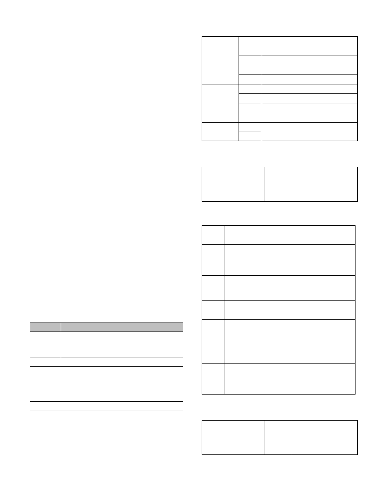
AIR HANDLER CONTROL 9−PIN CONNECTOR (P8)
1. Air Handler (no electric heat) Two wire factory
harness (wired to pins 7 and 8) which provides 230
VAC power to Air Handler Control.
2. Air Handler (with electric heat) Eight wire factory
harness (all pin position are wired as noted in table 5).
NOTE See figure 15, detail B for wire colors.
Table 5. Electric Heat Connection (P8)
Position Function / Description
1 Heat stage 1 relay coil
2 Heat stage 2 relay coil
3 Relay coil return
4 Heat stage 3 relay coil
5 Heat stage 4 relay coil
6 Heat stage 5 relay coil
7 L1 230VAC supply from heater kit
8 L2 230 VAC supply from heater kit
9 Not Used
CONTROL CONNECTIONS AND WIRING
REQUIREMENTS
This sections provides information on communicating and
non−communicating control connections and wire run
lengths.
Table 6. Air Handler Control Connections
Communicating
Label Label Function
R 24VAC
Thermostat
Outdoor Unit
Link
i+ RSbus data high connection
i− RSbus data low connection
C 24VAC command (ground)
R 24VAC
i+ RSbus data high connection
i− RSbus data low connection
C 24VAC command (ground)
i+
Not used.
i−
Table 7. Run Length Communicating
Wire Run Length AWG # Insulation/Core Types
Maximum length of wiring
for all connections on the
RSbus is limited to 1500
feet (457 meters).
18
Color−coded, temperature
rating 95ºF (35ºC) minimum,
solid core. (Class II Rated
Wiring)
Table 8. Air Handler Control Connections
Non−Communicating
Label Function
W1 First−stage heating demand.
Second stage heating demand. W1 input must be active to
W2
recognize second stage heat demand. .
Third stage heating demand. W1 and W2 inputs must be
W3
active to recognize third stage heat demand.
G 24VAC signal indicates the presence of a demand.
Y1 and
First and second stage cooling inputs.
Y2
C 24VAC common.
R 24VAC power.
DH Use in communicating system only
H 24VAC output for humidification.
L Use in communicating system only
Reversing Valve input. (Energized by thermostat in cooling
O
mode.)
Blower speed control input for Harmony Zoning or thermo-
DS
stat de−humidification control.
Blower speed control input for Harmony Zoning or thermo-
DS
stat de−humidification control.
Table 9. Run Length Non−Communicating
Wire Run Length AWG # Insulation/Core Types
Less than 100’ (30m) 18
More than 100’ (30m) 16
Color−coded, temperature
rating 95ºF (35ºC) minimum,
solid core. (Class II Rated
Wiring)
Page 19
CBX32MV SERIES
Page 20

CBX32MV / CBX40UHV
JUMPER & LINK GUIDE
COOLING MODE
BLOWER SPEED
(COOLING & HP MODE)
HIGH
SPEED
1
2
3
4
*
MEDIUM−HIGH
SPEED
1
2
3
4
MEDIUM−LOW
SPEED
1
2
3
4
LOW
SPEED
1
2
3
4
HEATING MODE
BLOWER SPEED
(ELECTRIC HT MODE)
*
HIGH
SPEED
1
2
3
4
MEDIUM−HIGH
SPEED
1
2
3
4
MEDIUM−LOW
SPEED
1
2
3
4
LOW
SPEED
1
2
3
4
PUSH
BUTTON
2−STAGE
ON−BOARD LINK
OPTION SELECTION
1
(JUMPERS Y1 to Y2)
COMPRESSOR LINK
HEAT PUMP LINK
(JUMPERS R to O)
HARMONY LINK
(JUMPERS R to DS)
DEHUMIDIFICATION−
1−STG COMPRESSOR
*
DO NOT CUT
Y1−Y2
COMPR
2 STAGE
A/C UNIT HEAT PUMP UNIT
*
DO NOT CUT
R−0
HEAT
PUMP
NO HARMONY ZONING
*
OR NO
COMFORTSENSE 7000
W/ DS CONNECTION
DO NOT CUT
2−STG COMPRESSOR
or
R−DS
DEHUM
HARMONY
CUT LINK
Y1−Y2
COMPR
2 STAGE
CUT LINK
1
R−0
HARMONY ZONING
C0MFORTSENSE 7000
W/ DS CONNECTION
1
CUT LINK
OR
HEAT
PUMP
R−DS
1
or
DEHUM
HARMONY
FUSE 3 AMP
XFMR 24V
24 VAC
COM
1
3
2
4
6
5
9
8
7
XFMR LINE
L2 L1
G
EARTH
INDOOR BLOWER
SIGNAL
456
12 3
BLOWER
ADJUST SELECTION
*
NORMAL
NORM
+
−
(+ 10%)
SETTING
NORM
+
−
(−10%)
SETTING
NORM
+
−
HEAT
1234
COOL
1234
DELAY
I + I −
LINK
1234
ADJUST
NORM + −
I + I −RC
OUTDOOR UNIT
P8
L1L2
INDOOR
BLOWER
POWER
7−SEGMENT LED
COOLING BLOWER RAMPING
(COOLING MODE UNLESS NOTED)
*
DELAY
PROFILE #4
OFF−50%−82%−
100%−50%−OFF
DELAY
PROFILE #3
OFF−82%−100%−OFF
DELAY
PROFILE #2
COOLING
OFF−100%−100%−OFF
HP
OFF−30sOFF−100%−100% OFF
DELAY
PROFILE #1
OFF−100%−OFF
HUMIDITROL
DH
C
HUMIDIFICATION
SMART AUTO
EVENHEAT
85
BLOWER
ONLY CFM
1234
I + I −RC
THERMOSTAT
2−STAGE
COMPR
R−DS
R−O
HARMONY
Y1−Y2
OR
DEHUM
HEAT
PUMP
−CUT ON−BOARD LINK (SOLDER TRACE) COMPLETELY
1
THROUGH BOTH LAYERS ON THE CONTROL BOARD
IMPORTANT: USE CARE WHEN CUTTING LINKS TO
PREVENT DAMAGE TO CONTROL.
HUMIDIFICATION MODE
115
100
130
O
L
H
STANDARD HEAT MODE
(DEFAULT)
DH
R
DS
C
Y1
Y2
STANDARD
HEAT MODE
(STAGED BY TSTAT)
85
110
115
G
W3
W2
W1
FACTORY
OUTDOOR
DISCHARGE
AIR SENSOR
AIR SENSOR
CONTINUOUS FAN
BLOWER SPEED
HIGH
SPEED
4
4
(100%)
MEDIUM−HIGH
SPEED
(70%)
MEDIUM−LOW
*
SPEED
(38%)
LOW
SPEED
(28%)
1
2
3
4
1
2
3
4
1
2
3
1
2
3
JUMPER
1
2
3
4
1
2
3
4
1
2
3
4
1
2
3
4
EVENHEATER
−ENABLED WITH OPTIONAL
DISCHARGE AIR SENSOR
*
DEGREE TARGET
DISCHARGE
TEMPERATURE
DEGREE
TARGET
DEGREE
TARGET
DEGREE
TARGET
MODE
85
85
110
115
100
85
110
115
130
115
85
110
115
130
130
85
110
115
130
FACTORY DEFAULT SETTING
*
HUMIDIFICATION MODE
24VAC OUTPUT ON ”H”
ACCESSORY INTERLOCK
*
SMART MODE
− ”H” ENABLED WHEN
HEAT ACTIVE
(HP or ELECT. HT)
130
AUTO MODE
− ”H” ENABLED WHEN
BLOWER ACTIVE
& NO CLG
OR DEHUM
130
FOR HUMIDIFIER OR
SMART
SMART
AUTO
AUTO
Figure 21. Air Handler Configuration
Page 20
Page 21

Air Handler Control Button, Display and
F
Jumpers
Use figure 21 as reference for jumper settings. If any of the
reference jumpers are missing, the Air Handler Control will
display Error Code 130 as per table 10, and the Air Handler
Control will automatically use the factory default setting
show in figure 21)
IMPORTANT
Before changing any clippable links or jumper settings,
make sure the motor has completely stopped. Any
changes will not take place while the motor is running.
PUSH BUTTON
An on−board push button is provided for the purpose of
placing the Air Handler Control in different operation
modes and can be used to recall stored error codes. When
button is pushed and held, Air Handler Control will cycle
through a menu of options depending on current operating
mode. Every three seconds a new menu item will be
displayed. If the button is released while that item is shown
on the display, Air Handler Control will enter displayed
operating mode, or execute defined operation sequence
for that menu option. Once all items on menu have been
displayed the menu resumes from the beginning (if button
is still held).
1. Press the diagnostic push button and hold it to cycle
through a menu of options. Every five seconds a new
menu item will be displayed. Release the button when
the desired mode is displayed.
2. When the solid E" is displayed, the control enters the Error
Code Recall mode. Error Code Recall mode menu options:
No change (displaying error history) remains in Error Code
Recall mode; solid " exits Error Code Recall mode; and
solid c" clears the error history. Must press button while
flashing c" is displayed to clear error codes
3. When the solid −" is displayed, the control enters the
applicable mode. Field configuration mode menu options:
Solid C" starts pressure switch calibration; blinking −" exits
current active mode.
JUMPERS
Jumpers are used for non−communicating mode only.
1. Humidification Controls the status of H terminal
on the thermostat block. Configurations are as follows:
S If jumper is installed in SMART Humidification
position (Default), H terminal is active if heat
demand is present and indoor blower is
running.
S If jumper is installed in AUTO Humidification
position, H terminal is energized whenever
indoor blower is running.
2. EvenHeat Target Discharge Air Temperature
selection is used to set discharge air temperatures for
EvenHeat operation.
NOTE − Optional Discharge Air Temperature Sensor,
Lennox Catalog # 88K38 is REQUIRED for EVENHEAT
operation and must be ordered separately.
Page 21
3. Blower Only CFM Used to select Indoor blower
CFM for continuous operation.
4. Heat Used to select Indoor blower CFM for
electrical heat by placing the jumper in proper position.
Actual CFM values for different air handler sizes are
shown in Targeted CFM tables starting on page 25.
5. Cool Used to select cooling indoor blower CFM by
placing the jumper in proper position. Actual CFM
values for different air handler sizes are shown in
Targeted CFM tables starting on page 25.
6. Adjust − Used to select the indoor blower CFM
adjustment value by placing the jumper in appropriate
position.
S If NORM is selected, indoor blower runs at
normal speeds.
S If + is selected, indoor blower runs at
approximately 10% higher speed than NORM
setting.
S If − is selected, indoor blower runs at
approximately 10% lower speed than NORM
setting.
If the jumper is missing, the Air Handler Control will
activate the Configuration Jumper is Missing alarm in
and will automatically use the default factory setting in
table 10. See figure 21 for jumper configurations.
Actual CFM values for different air handler sizes are
shown in Targeted CFM tables starting on page 25.
7. Delay Indoor blower cooling profile, delay for
cooling and heat pump operations.
S When operating a heat pump, delay profiles 1
and 2 are only applicable.
S When operating a heat pump, and profiles 3
and 4 are selected, the Air Handler Control will
default to profile 1.
If the jumper is missing, the Air Handler Control will
activate the Configuration Jumper is Missing alarm
and will automatically use the default factory setting in
table 10. See figure 21 for jumper configurations.
Delay Profile 1
A When cool or heat demand is initiated, motor
ramps up to 100% and runs at 100% until demand
is satisfied.
B Once demand is met, motor ramps down to stop.
B
100%
A
Cooling Air Conditioner and Heat Pump:
OFF
A
A When cool demand is initiated, motor ramps up to
100% and runs at 100% until demand is satisfied.
CFM
COOLING
DEMAND
Delay Profile 2
BC
100% CFM
COOLING
DEMAND
OFFOFF
100% CFM
45 SEC.
OF
CBX32MV SERIES
Page 22

B Once demand is met, motor runs at 100% for 45
F
seconds.
C Motor ramps down to stop.
Heating Heat Pump only:
OFF
AB
30 sec
delay
100% CFM
HEATING DEMAND
C
100% CFM
45 SEC.
D
A When heat demand is initiated, 30 seconds motor
on delay starts
B After the motor on delays expires, motor ramps up
to 100% and runs at 100% until demand is
satisfied.
C Once demand is met, motor runs at 100% for 45
seconds.
D Motor ramps down to stop.
Delay Profile 3
C
OFF
B
A
7 1/2 MIN
82%CFM
COOLING DEMAND
100% CFM
A When cool demand is initiated, motor ramps up to
82%
Table 10. AHC System Status Codes
OFF
OF
B Motor runs at 82% for approximately 7.5 minutes
and then ramp up to 100% (unless the demand
has been satisfied) and motor runs at 100% until
demand is satisfied.
C Once demand is met, motor ramps down to stop
Delay Profile 4
C
OFF
A
B
1/2 MIN
50% CFM
7 1/2 MIN
82% CFM
COOLING DEMAND
100%
CFM
D
1/2 MIN
50% CFM
E
OFF
A When cool demand is initiated, motor ramps up to
50%
B Motor runs at 50% for 30 seconds and ramps up to
82%
C Motor runs at 82% for approximately 7.5 minutes
and then ramp up to 100% (unless the demand
has been satisfied) and motor runs at 100% until
demand is satisfied.
D Once demand is met, motor runs at 50% for 30
seconds.
E Motor ramps down to stop.
DISPLAY
An on−board single character LED display (see figure 21
for LED display location) indicates general system status
information such as mode of operation, indoor blower CFM
and error codes. Multi−character strings are displayed with
character ON for one second, OFF for 0.5 seconds and
one second pause between the character groups.
AHC Single Character
Display
Letter or Number
.
Action
Unit Size Code displayed represents air handler model size and capacity. See Configuring Unit Size Codes in figure
23.
If three horizontal bars are displayed, AHC does not recognize air handler model size and capacity. See Configuring
Unit Size Codes in Figure 23.
Idle mode (decimal point / no unit operation)
Cubic feet per minute (cfm) setting for indoor blower (1 second ON, 0.5 second OFF) / cfm setting for current mode
displayed. Example:
Cooling stage (1 second ON, 0.5 second OFF) / 1 or 2 displayed / Pause / cfm setting displayed / Pause / Repeat
codes). Example or
Dehumidification mode (1 second ON) / 1 second OFF) / cfm setting displayed / Pause / Repeat Codes)
Defrost mode. (Y, W and O call)
Heat Stage (1 second ON, 0.5 second OFF) / 1 or 2 displayed / Pause / cfm setting displayed / Pause / Repeat codes.
Example: or or
Variable Capacity Heat (1 second ON, 0.5 second OFF) / % of input rate displayed / Pause/ cfm setting / Pause/ Repeat codes. Example: or
Discharge air sensor temperature (indoor blower must be operating)
Page 22
Page 23
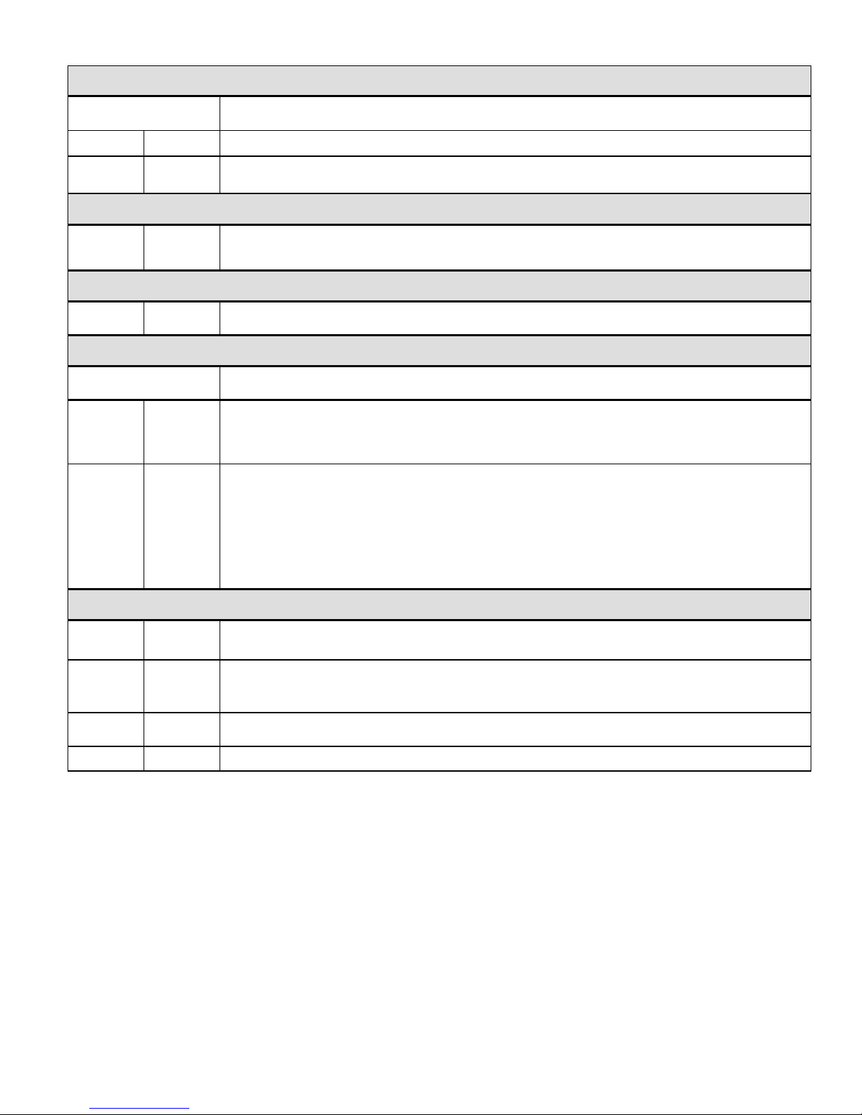
Table 11. AHC Configuration, Test and Error Recall (Fault and Lockout) Function
NOTE AHC MUST BE IN IDLE MODE)
Single Character LED
Display
Solid
Blinking
Action
Push and hold button until solid appears, release button. Display will blink.
Push and hold button until required symbol displays. or
CONFIGURING ELECTRIC HEAT SECTIONS
Release push button − control will cycle the indoor blower motor on to the selected heat speed and stage the electric
Solid
heat relays on and off to automatically detect number of electric heat sections. Control will store the number of electric
heat sections. Control will automatically exit current active mode.
INDOOR BLOWER TEST
Solid
Release push button − control cycles indoor blower on for ten seconds at 70% of maximum air for selected capacity
size unit. Control will automatically exit current active mode.
CONFIGURING UNIT SIZE CODES
Single Character LED
Display
Solid
Blinking
Action
RELEASE push button − This mode allows the field to select a unit size code (number or letter) that matches the air
handler model size and capacity.
IMPORTANT All field replacement controls may be manually configured to confirm air handler model size
and capacity.
1. When the correct Unit Sized Code is displayed, RELEASE push button. Selected code will flash for 10 second
period.
2. During ten second period, HOLD push button until code stops blinking (three seconds minimum).
3. Air Handler Control will store code in memory and exit
the Unit Size Code will display for 2 to 5 seconds.
NOTE − If ten second period expires, or push button is held less than 3 seconds, control will automatically exit current
active mode and go into IDLE Mode without storing unit size code. If this occurs, then Unit Size Code configuring
procedure must be repeated.
current active mode. LED display will go blank and then
ERROR CODE RECALL MODE (NOTE CONTROL MUST BE IN IDLE MODE)
Solid
Solid
Solid
Blinking
To enter Error Code Recall Mode PUSH and HOLD button until solid E appears, then RELEASE button.
Control will display up to ten error codes stored in memory. If E000 is displayed, there are no stored error codes.
To exit Error Code Recall Mode PUSH and HOLD button until solid three horizontal bars appear, then
RELEASE button.
NOTE − Error codes are not cleared
To clear error codes stored in memory, continue to HOLD push button while the three horizontal bars are displayed.
Release push button when solid c is displayed. Display will blink.
Push button to confirm command to delete codes. Error codes are cleared.
Page 23
CBX32MV SERIES
Page 24

Table 12. AHC Single Character Display Alert Codes (Communicating and Non−Communicating)
Alert Code
Error codes 401 through 409 are only displayed when the Control’s L terminal is connected to a non−communicating outdoor unit’s LSOM device..
** Cutback Mode The variable speed motor has pre−set speed and torque limiters to protect the motor from damage caused by operating out of its
designed parameters (0 through 0.80 in. w.g. total external static pressure).
Status of Air Handler
Device communications problem − No other devices on BUS (Communication system).
No 60 hertz power (Check voltage and frequency)
Low 24 volts (18 or less volts) − Control will restart if the error recovers.
Unresponsive Device2 − Indicates a device on the RSbus is not responding to a message sent to it by another device.
Error code is applicable to all communicating devices on the RSbus (thermostat, indoor and outdoor units). Normally
indicates a malfunctioning device.
Active Subnet Controller Missing for > 180 seconds. This indicates a data connection has been lost between a communicating device and the communicating thermostat. Device (indoor or outdoor unit) sends the alarm if no communication is established between device and thermostat within three minutes.
Configuration jumper(s) is missing on AHC.
Non−volatile data corruption.
Failed Flash CRC check.
Outdoor air temperature sensor (OAS) out of range.
Indoor Blower communication failure − (includes indoor blower power outage)
Incorrect air handler model size and capacity selected or wrong motor. Check for proper configuring under Configuring
Unit Size Codes.
No air handler model size and capacity selected. Check for proper configuring under Configuring Unit Size Codes.
Indoor blower motor unable to start (seized bearing, stuck wheel, etc.).
Indoor blower motor over temperature (motor trip on internal protector)
Discharge air temperature sensor (DATS) out of range.
Restricted airflow Indoor blower motor is running at a reduced CFM (cutback mode **)
Indoor and outdoor unit capacity mismatch.
Global network connection error. This usually indicates there is a short or overladed resistance is to low) condition
between communicating indoor and thermostat units.
Jumper for second−stage cooling not removed.
Jumper for heat pump operation not removed.
Relay Y1 failure.
Relay Y2 failure.
Heat call with non−configured or mis−configured electric heat. Check for proper configuring under Configuring Electric
Heat Stages.
Heat section / Stage 1 failed (Pilot relay contacts did not close or the relay coil in electric heat did not energizing)
Heat section / Stage 2 failed.
Heat section / Stage 3 failed.
Heat section / Stage 4 failed.
Heat section / Stage 5 failed.
Defrost out−of−control
Compressor ran more than 18 hours in air conditioning mode.
Compressor system pressure trip.
Compressor short−cycling − running less than four minutes.
Compressor rotor locked.
Compressor open circuit.
Compressor open start circuit.
Compressor open run circuit.
Compressor contactor is welded.
Compressor low voltage.
Page 24
Page 25
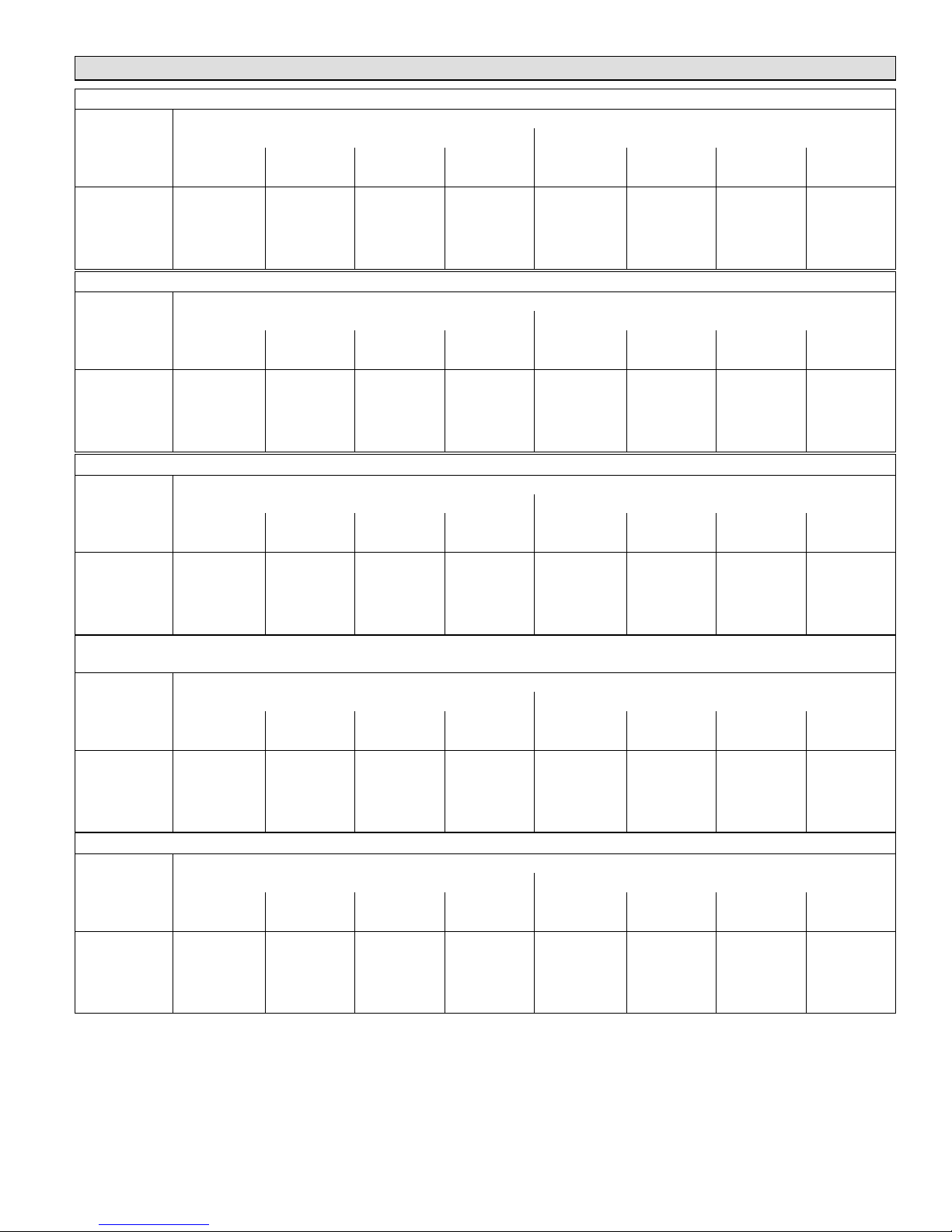
Target CFM Tables
CBX32MV-018/024 BLOWER PERFORMANCE 0 through 0.80 in. w.g. (0 through 200 Pa) External Static Pressure Range
ADJUST
Jumper
Setting
+ 715 337 855 405 1000 470 1130 535 465 220 690 325 900 425 1050 495
NORM 670 315 770 365 900 425 1035 490 425 200 620 290 825 390 950 450
− 580 275 700 330 800 375 930 440 385 180 560 265 735 345 850 400
1 2 3 4 1 2 3 4
cfm L/s cfm L/s cfm L/s cfm L/s cfm L/s cfm L/s cfm L/s cfm L/s
HEAT Speed COOL Speed
CBX32MV-024/030 BLOWER PERFORMANCE 0 through 0.80 in. w.g. (0 through 200 Pa) External Static Pressure Range
ADJUST
Jumper
Setting
+ 800 380 935 440 1070 505 1210 570 660 310 880 415 1100 520 1320 625
NORM 725 340 850 400 975 460 1100 520 600 285 800 380 1000 470 1200 565
− 655 310 765 360 880 415 990 470 540 255 720 340 900 425 1080 510
1 2 3 4 1 2 3 4
cfm L/s cfm L/s cfm L/s cfm L/s cfm L/s cfm L/s cfm L/s cfm L/s
HEAT Speed COOL Speed
CBX32MV-036 BLOWER PERFORMANCE 0 through 0.80 in. w.g. (0 through 200 Pa) External Static Pressure Range
ADJUST
Jumper
Setting
+ 1230 580 1335 630 1445 680 1545 730 1090 515 1225 580 1380 650 1545 730
1 2 3 4 1 2 3 4
cfm L/s cfm L/s cfm L/s cfm L/s cfm L/s cfm L/s cfm L/s cfm L/s
HEAT Speed COOL Speed
Jumper Speed Positions
Jumper Speed Positions
Jumper Speed Positions
NORM 1120 530 1215 575 1315 620 1400 660 975 460 1125 530 1275 600 1400 660
− 1010 475 1185 560 1200 565 1265 595 900 425 1000 470 1135 535 1265 595
CBX32MV-048 AND CBX32MV-060 BLOWER PERFORMANCE 0 through 0.80 in. w.g. (0 Through 200 Pa) External Static
Pressure Range
Jumper Speed Positions
ADJUST
Jumper
Setting
+ 1850 875 1960 925 2090 985 2150 1015 1625 765 1820 860 2055 970 2145 1010
NORM 1705 805 1800 850 1900 895 2005 945 1425 670 1625 765 1805 850 2005 945
− 1560 735 1625 765 1720 810 1770 835 1205 570 1375 650 1555 735 1725 815
1 2 3 4 1 2 3 4
cfm L/s cfm L/s cfm L/s cfm L/s cfm L/s cfm L/s cfm L/s cfm L/s
HEAT Speed COOL Speed
CBX32MV-068 BLOWER PERFORMANCE 0 through 0.80 in. w.g. (0 Through 200 Pa) External Static Pressure Range
Jumper Speed Positions
HEAT Speed COOL Speed
ADJUST
Jumper Setting
+ 1875 885 1975 930 2090 985 2150 1015 1640 775 1840 870 2075 980 2150 1015
NORM 1760 830 1825 860 1920 905 2030 960 1465 690 1625 765 1800 850 2000 945
− 1550 730 1650 780 1725 815 1800 850 1250 590 1390 655 1560 735 1720 810
NOTES − The effect of static pressure, filter and electric heater resistance is included in the air volumes listed.
First stage cooling air volume is 70% of COOL speed setting. Continuous blower speed is approximately 50% of COOL speed setting.
Lennox Harmony IIIt Zone Control applications − minimum blower speed is 300 cfm (145 L/s)
1 2 3 4 1 2 3 4
cfm L/s cfm L/s cfm L/s cfm L/s cfm L/s cfm L/s cfm L/s cfm L/s
Page 25
CBX32MV SERIES
Page 26

Unit Operating Sequences
This section details unit operating sequence for non−communicating systems.
NOTE − For communicating systems, see the icomfort Toucht thermostat installation instruction.
Table 13. CBX32MV with ComfortSenset 7000 Thermostat and Single−Stage Outdoor Unit Operating
Sequence
Operating Sequence System Demand System Response
System
Condition
Normal Operation 1 On On On Acceptable 24 VAC High 100%
Normal Operation 1 On On On Acceptable 24 VAC High 100%
Dehumidification
Call
Normal Operation 1 On On On Acceptable 24 VAC High 100%
Dehumidification
call
Dehumidification
call ONLY
Step
2 On On On Demand 0 VAC High 70%
2 On On On Demand 0 VAC High 70%
1 On On On Demand 0 VAC High 70%
Thermostat Demand Relative Humidity
Comp
Y1 Y2 O G W1 W2 Status D
NO CALL FOR DEHUMIDIFICATION
BASIC MODE (Only active on a Y1 thermostat demand)
PRECISION MODE (Operates independent of a Y1 thermostat demand)
Air
Handler
CFM
(COOL)
Compressor and indoor
air handler follow
thermostat demand
ComfortSenset 7000
thermostat energizes Y1
and de−energizes D on a
call for dehumidification.
NOTE − No over cooling.
Dehumidification mode
begins when humidity is
greater than set point
ComfortSenset 7000 will
keep outdoor unit
energized after cooling
temperature setpoint has
been reach in order to
maintain room humidity
setpoint.
NOTE − Allow to over
cool 20F from cooling set
point.
Comments
Page 26
Page 27

Table 14. CBX32MV with ComfortSenset 7000 Thermostat and Two-Stage Outdoor Unit Operating Sequence
Operating Sequence System Demand System Response
Thermostat Demand Relative Humidity
System
Condition
Step
Y1 Y2 O G W1 W2 Status D
Compre
ssor
No Call for Dehumidification
Normal Operation
− Y1
Normal Operation
− Y2
1 On On On Acceptable 24 VAC Low 70%
2 On On On On Acceptable 24 VAC High 100%
Room Thermostat Calls for First−Stage Cooling
BASIC MODE (Only active on a Y1 thermostat demand)
Normal Operation 1 On On On Acceptable 24 VAC Low 70%
Dehumidification
Call
2 On On On On Demand 0 VAC High 70%
PRECISION MODE (Operates independent of a Y1 thermostat demand)
Normal Operation 1 On On On Acceptable 24 VAC Low 70%
Dehumidification
call
Dehumidification
call ONLY
2 On On On On Demand 0 VAC High 70%
1 On On On On Demand 0 VAC High 70%
Room Thermostat Calls for First− and Second−Stage Cooling
BASIC MODE (Only active on a Y1 thermostat demand)
Normal Operation 1 On On On On Acceptable 24 VAC High 100%
Dehumidification
Call
2 On On On On Demand 0 VAC High 70%
PRECISION MODE (Operates independent of a Y1 thermostat demand)
Normal Operation 1 On On On On Acceptable 24 VAC High 100%
Dehumidification
call
Dehumidification
call ONLY
2 On On On On Demand 0 VAC High 70%
1 On On On On Demand 0 VAC High 70%
Air
Handler
CFM
(COOL)
Comments
Compressor and indoor air
handler follow thermostat
demand
ComfortSenset 7000 ther-
mostat energizes Y2 and de−
energizes D on a call for
dehumidification
NOTE − No over cooling.
Dehumidification mode begins
when humidity is greater than
set point
ComfortSenset 7000
thermostat will keep outdoor
unit energized after cooling
temperature setpoint has
been reached in order to
maintain room humidity
setpoint.
NOTE Allow to over cool
20F from cooling set point.
ComfortSenset 7000 ther-
mostat energizes Y2 and de−
energizes D on a call for
dehumidification
NOTE No over cooling.
Dehumidification mode begins
when humidity is greater than
set point
ComfortSenset 7000
thermostat will keep outdoor
unit energized after cooling
temperature setpoint has
been reached in order to
maintain room humidity
setpoint.
NOTE Allow to over cool
20F from cooling set point.
Page 27
CBX32MV SERIES
Page 28

Configuring Unit
This section identifies the requirements for configuring the air handler unit for unit size, heat mode selection and EvenHeat.
Air Handler Control Checkout
Power−up − Unit Size Code (Number or letter) displayed represents air handler model size and
capacity. If three horizontal bars displays, Air Handler Control (AHC) does not recognize unit size code
(air handler model size and capacity).
Finished
After all electric heat installations, AHC must be
manually configured to detect number of heat
sections. Refer to Configuring/Detecting electric heat
sections flow diagram, Air Handler or ECB40 Electric
Heat installation
No
Refer to Heat Pump or Cooling
Sequence of Operation flow
diagrams, Air Handler or ECB40
Electric Heat installation
instructions.
Electric
heat
Installed?
Ye s
W1 Call?
Ye s
Ye sNo
Standard
AHC
recognizes
Unit Size
Code?
Which Heat
Mode?
No (Display Alarm
Code 203)
Refer to Configuring Unit Size Codes flow diagram, Air Handler or
ECB40 Electric Heat installation instructions.
IMPORTANT Field replacement controls may need to be manually
configured to validate air handler unit size code.
EVENHEAT
Refer to EVENHEAT Operation flow diagram, Air Handler or
ECB40 Electric Heat installation instructions.
NUMBER OF HEAT SECTIONS DETECTED
T−STAT CALL
W1
W2
W3
RECOMMEND USE FIGURE 21 AS A REFERENCE FOR SETTING JUMPER CONFIGURATIONS ON THE AIR HANDLER CONTROL.
ONE (H1)
TWO (H1−H2)
H1
A call for electric heating first, second or third stage is
initiated when 24 VAC (R) is detected on W1, W2 and
W3 inputs on AHC. (Factory mounted metal jumpers
connect W1/2 and W2/W3.)
Indoor blower will immediately start to delivery CFM
as set by heating mode jumper on AHC with
activation of first electric heat pilot relay.
H1
H2
H2
THREE (H1−H3)
H1
H2
H3
FOUR (H1−H4)
H1 AND H2
H3
H4
FIVE (H1−H5)
H1 AND H2
H3 AND H4
H5
Pilot relays on AHC are energized one at a time.
There is a minimum of 10 seconds delay between
pilot relay activations.
NOTE − AHC will not recognize higher heat sections
calls if lower heat section is not present.
At the completion of each heat section demand (W1,
W2, and W3), the AHC will immediately de−energize
the corresponding pilot relay(s).
NOTE If the call for lower heat section is removed,
AHC will automatically de−energize higher heat
sections.
At the completion of all heating demands, the indoor
blower will run for an additional 10 seconds before
de−energizing.
Figure 22. Air Handler Control Checkout
Page 28
Page 29

Configuring Unit Size Codes (Model Number)
Power−up Unit Size Code (number or letter) displayed represents unit size code (air handler model size and capacity).
If three horizontal bars display, then Air Handler Control (AHC) does not recognize unit size code.
To enter unit size code
configuration mode; PUSH and
HOLD button next to single
character LED display until dash
symbol appears, RELEASE button.
Solid dash starts blinking
on single character LED
PUSH and HOLD button until the solid P
symbol is displayed on the single
character LED display, then RELEASE
button. This mode allows the user to
select a unit size code (number or letter)
that matches the air handler model size
display.
and capacity.
Ye s
(No heating, cooling or indoor fan operation)
AHC in IDLE mode
No
UNIT SIZE
CODE
0
1
2
3
4
5
6
7
8
9
L
U
Turn room thermostat to
OFF
AIR HANDLER
MODEL
CBX32MV−018/024
CBX32MV−024/030
CBX32MV−036
CBX32MV−048
CBX32MV−060
CBX32MV−068
CBX40UHV−024
CBX40UHV−030
CBX40UHV−036
CBX40UHV−042
CBX40UHV−048
CBX40UHV−060
IMPORTANT Field replacement controls may need to be
manually configured to validate air handler unit size code.
Solid P starts
blinking on single
character LED
display.
PUSH and HOLD button to allow AHC to display unit size
code (letter or number) for each different air handler model
for three seconds.
Figure 23. Configure Unit Size Codes
1. When the correct Unit Sized Code is displayed, RELEASE
push button. Selected code will flash for 10 second period.
2. During that 10 second period, HOLD push button until code
stops blinking (three seconds minimum).
3. Air Handler Control will store code in memory and exit current
active mode. LED display will go blank and then the Unit Size
Code will display for 2 to 5 seconds.
NOTE − If 10 second period expires, or push button is held less than
three seconds, control will automatically exit current ative mode and
go into IDLE Mode without storing unit size code. If this occurs, then
Unit Size Code configuring procedure must be repeated.
LED displays correct
NO
Unit Size Code.
YES
Unit enters IDLE
Mode.
Page 29
CBX32MV SERIES
Page 30

Configuring/Detecting Electric Heat Sections
IMPORTANT All electric heat installations require the Air Handler Control (AHC) to be manually
configured to detect number of heat sections.
NOTE All field replacement AHC will require configuring/detecting electric heat sections.
RECOMMEND USE FIGURE 21 AS A REFERENCE FOR SETTING
JUMPER CONFIGURATIONS ON THE AIR HANDLER CONTROL.
Standard EVENHEAT
Which Heat
Mode?
S Set desired Heating Mode Blower Speed jumper
pin.
S Electric heat is stages by room thermostat. (AHC
comes with factory jumper between W1 to W2 and W2
to W3)
S Refer to Air Handler Control Checkout flow diagram for
operation.
Ye s
To enter electric heat mode
configuration, push and hold button
next to single character LED display
until dash symbol (solid bar)
appears, then release button.
Solid dash
starts
blinking on
single
character
LED
display
S Set desired Heating Mode Blower Speed jumper
pin.
Configuration
AHC in Idle Mode
(No heating cooling or
indoor fan operation)
Push and hold button until the solid H symbol is displayed on the single
character LED display, then release button.
S Install and wire discharge air temperature sensor.
S Set desired Target Discharge Temperature jumper
pin. If jumper pin is missing or discharge air
temperature sensor is not detected, AHC defaults to
Standard Heat Mode. Target settings are 85, 100, 115
and 130ºF) .
S Refer to EVENHEAT Operation flow diagram for
operation.
No
Turn room thermostat to OFF.
1. AHC will start the indoor blower motor to the selected heat jumper speed setting and cycle the electric heat relays ON to automatically detect number of electric
heat sections. (Electric heat section may be wired to energize more than one element)
2. AHC waits for maximum of ten seconds to detect electric heat 22 volt DC relay coils are energizing:
A If relay coil current is detected within ten seconds,
each additional heat section is detected, single character LED display on the AHC will display that electric element number. (Example: Last number displayed
by the single character LED display is 3, the AHC is configured to operate three electric heat sections.)
B If relay coil current is not detected within ten seconds,
3. AHC will automatically exit current configuration mode when configuration is completed. To verify that the number of electric sections detected matches the
installed electric heat package, the field MUST CONFIRM that the last number the single character LED display before exiting the Configuring/Detection Mode
matches the number of installed electric heat sections. AHC stores the number of electric heat stages in non−volatile memory.
4. After the detection is finished, unit will continue to operate for an additional 30 seconds.
NOTE If AHC push button is pushed or power is cycled on AHC is unable to verify all 22 volt DC electric heat relay(s) were energized using electric heater
detection, configuration will be stopped. Configuration function must be repeated.
AHC will show a 1 on the single character LED display indicating that the first stage has been detected. As
the AHC will exit the current active mode and resume operation with electric heat disabled.
Finished
Figure 24. Heat Mode Selection
Page 30
Page 31

INPUTS OUTPUTS
Room Thermostat Demand
Target Discharge Air
Temperature Set at 85ºF
Y1 Heat Pump First Stage Heat Pump First Stage
Y1 + Y2
Y1 + W1 and/or W2
Heat Pump First and Second
Stage
Heat Pump First Stage + First
Electric Heat Section (H1)
Heat Pump First and Second
Y1 and Y2 + W1 and/or W2
Stage+ First Electric Heat Section
(H1)
W1 and/or W2 First Electric Heat Section (H1)
EVENHEAT OPERATION
Target Discharge Air
Temperature Set at 100ºF
Heat Pump First and Second Stage
+ First Electric Heat Section (H1)
Heat Pump First Stage + First
Electric Heat Section + Second
Electric Heat Section (H2) if number of electric heater sections detected is more than two.
Heat Pump First and Second Stage
+ First Electric Heat Section + Second Electric Heat Section (H2) if
number of electric heater sections
detected is more than two.
First Electric Heat Section (H1) +
Second Electric Heat Section (H2)
if number of electric heater sections detected is more than two.
Target Discharge Air
Temperature Set at 115ºF/130ºF
Heat Pump First + First Electric
Heat Section (H1)
Heat Pump First and Second Stage
+ First Electric Heat Section (H1) +
Second Electric Heat Section (H2)
if number of electric heater sections detected is more than two.
Heat Pump First Stage + First
Electric Heat Section (H1) Second
Electric Heat Section (H2) if number of electric heater sections detected is more than two.
Heat Pump First and Second Stage
+ First Electric Heat Section (H1)
Second Electric Heat Section (H2)
if number of electric heater sections detected is more than two.
First Electric Heat Section (H1) +
Second Electric Heat Section (H2)
if number of electric heater sections detected is more than two.
Heat pump first or second stage or electric heat demand will start the
Air Handler Control (AHC) indoor blower at CFM value based on
tables found in installation instructions.
Ye s
No
Last room thermostat Heat
Timer delays for
120 seconds
Heat Pump and electric heat
demand?
One Stage More than one stage
Increase target discharge air temperature by 15Fº
up− staging action
Timer delays for 150
seconds
A
Figure 25. EVENHEAT Operation (1 of 2)
Page 31
CBX32MV SERIES
Page 32

Note 1 Activation delay
S 120 seconds if one heat stage is or deactivated
S 150 seconds if more than one stage is activated or deacti-
vated.
EVENHEAT Operation
Start Timer Delay
(Note 1)
Ye s
No
Adjust Target
Discharge Air
Temperature
Delay Timer
Finished or last
change was up−
stage
Ye s
Electric heat ON
Ye s
W call with one
Electric Heat
Section ON
No
No
Above
Change in Heat
demand from
room thermostat?
Stop Delay Timer
Increase heat demand.
Y1 (with or without Y2) +
W1 and W2
Adjust Target Discharge Air
Temperature
Heat Pump OFF
Discharge air temperature sensor
setting on the Air Handler Control will
remain at set point on W1 demand and
be increased 15ºF for W2 demand.
Heat Pump ON
Discharge air temperature sensor
setting on Air Handler Control will
remain at set point. W1 demand will
increase set point 15ºF. W2 demand
will increase set point an additional
15ºF. (Total of 30ºF)
A
Below
No
Activate Y2
Delay Timer
Finished or last
change was
down−
stage
Ye s
Y1 ON and
Y2 OFF
No
More Electric
Heat
available
Ye s
No
Ye s
Adjust Target
Discharge Air
Temperature
Turn OFF Electric
Heat Section
Figure 26. EVENHEAT Operation (2 of 2)
Discharge air
temperature is
within target range?
Measured discharge air
temperature is above or
below
target range?
Page 32
Turn ON one
Electric Heat
section
NOTE Optional Outdoor Thermostat (Wired between
R and W3) will lockout electric elements 3, 4 and 5.
Page 33

Heat Pump Operation (Heating and Cooling)
Air Handler Control AHC) Indoor Blower Mode Speed and Profiles settings
1. Set Cooling Mode Blower Speed jumper pin . (Low and high indoor blower CFM settings are identical for
cooling and heat pump)
2. Set Blower Adjust Selection jumper pin.
3. Set Cooling Mode Blower Ramping jumper pin (Cooling calls − All ramping profiles are active) (Heating calls −
Only ramping profiles 1 and 2 are active. If profiles 3 or 4 are selected, AHC will default to profile 1)
A Profile 1 does not provide any ramping profiles.
B Profile 2 provides a 30 second indoor blower ON delay at the start of a heat pump heating demand. (45
4. Simultaneous Heat Pump and electric heat call: Indoor Blower will operate at the highest CFM requested by
Single or Two−Stage Unit
1. AHC on−AHC link must be cut between Y1 and Y2 to allow two stage cooling operation.
2. AHC on−AHC link must be cut between R and O to allow heat pump operation.
RECOMMEND USE FIGURE 21 AS A REFERENCE FOR SETTING
second indoor blower OFF delay)
the heat pump or the electric heat blower speed selection.
JUMPER CONFIGURATIONS ON THE AIR HANDLER CONTROL.
CUT ON−BOARD LINK
Y1−Y2 FOR
TWO−STAGE A/C
CUT ON−BOARD
LINK R −O.
IMPORTANT USE CARE WHEN CUTTING LINKS TO
PREVENT DAMAGE TO CONTROL. SEE FIGURE 21,
CBX32MV JUMP AND LINK GUIDE FOR FURTHER
DETAILS.
Y1−Y2
2−STAGE
COMPR
R−O
HEAT
PUMP
R−DS
DEHUM
OR
HARMONY
CUT FOR OPTION
Heating
Air Handler Control (AHC) receives inputs on Y1 terminal.
Y1 terminal on AHC is configured as input and passes signal
from room thermostat to outdoor unit.
NOTE The outdoor unit control directly controls the
outdoor unit operation.
Y1 input to the AHC will control the indoor blower according
to the cooling or heating mode blower speed
adjust selection jumper pins.
Room thermostat calls for
second stage?
Ye s
, ramping and
Ye s
Room thermostat
calls for first
stage?
Cooling
Air Handler Control (AHC) receives inputs on Y1 and O
terminals.
Y1 terminal on AHC is configured as input and passes signal
from room thermostat to outdoor unit.
NOTE The outdoor unit control directly controls the outdoor
unit operation.)
Y1 input to the AHC. Will control the indoor blower according
to the cooling mode blower speed
selection jumper pins.
, ramping and adjust
Ye s
No
De−energize Y2 terminal on AHC. Indoor
blower speed will reset to Y1 demand.
NOTE The outdoor unit control
directly controls the outdoor unit
operation.)
Ye s
Y2 terminal on AHC is
configured as input and
passes signal from
room thermostat to
outdoor unit.
NOTE The outdoor
unit control directly
controls the outdoor unit
operation.)
Still calling for second
Y2 terminal is an input
to the AHC. The
indoor blower will be
controlled according
to the jumper pin
selections.
stage?
No
Ye s
Page 33
Still calling for first
stage?
No
De−energize Y1 (and O in cooling) terminals on
AHC.
NOTE The outdoor unit control directly controls
the outdoor unit operation.
De−energize indoor blower per ramping profile.
CBX32MV SERIES
Page 34

Cooling Operation
Air Handler Control AHC) Indoor Blower Mode Speed and Profiles settings
1. Set Cooling Mode Blower Speed jumper pin.
2. Set Cooling Mode Blower Ramping jumper pin.
3. Set Blower Adjust Selection jumper pin.
Single or Two−Stage Unit
AHC on−board link must be cut between Y1 and Y2 to allow 2 stage
cooling operation.
Room thermostat
calls for first
stage?
Air Handler Control (AHC) receives inputs on Y1 terminal.
Y1 terminal on AHC is configured as input and passes signal
from room thermostat to outdoor unit.
NOTE − The outdoor unit control directly controls the outdoor
unit operation.
CUT ON−BOARD LINK Y1−Y2 FOR
TWO−STAGE A/C
RECOMMEND USE FIGURE 21 AS A REFERENCE FOR SETTING
JUMPER CONFIGURATIONS ON THE AIR HANDLER CONTROL.
IMPORTANT − Use care when cutting links to prevent damage to
control. See figure 21, CBX32MV jump and link guide for further
details.
Y1−Y2
2−STAGE
COMPR
R−O
HEAT
PUMP
R−DS
DEHUM
OR
HARMONY
CUT FOR OPTION
Y1 input to the AHC will control the indoor blower according to the cooling or
heating mode blower speed, ramping and adjust selection jumper pins.
Room thermostat calls for
second stage?
Ye sYe s
Y2 terminal on AHC is
configured as input and passes
signal from room thermostat to
outdoor unit.
NOTE − The outdoor unit
control directly controls the
outdoor unit operation.
Y2 terminal is an
input to the AHC.
The indoor blower
will be controlled
according to the
jumper pin
selections.
Ye s
Still calling for second
stage?
No
No
Ye s
De−energize Y2 terminal on AHC. Indoor
blower speed will reset to Y1 demand.
NOTE − The outdoor unit control directly
controls the outdoor unit operation.
Still calling for first
stage?
No
De−energize Y1 (and O in cooling) terminal
on AHC.
NOTE − The outdoor unit control directly
controls the outdoor unit operation.
De−energize indoor blower per ramping
profile.
Ye s
Page 34
Page 35

Error Code / Recall Mode
Ye s No
To enter Error Code Mode,
push and hold button next
to single character LED
display until solid E symbol
appears, release button.
Control will display up to ten error codes stored
in memory. If E 0 0 0 is displayed, there are no
stored error codes.
To exit Error Code Recall Model, push and hold
button next to single character LED display until
solid three horizontal bars appears, then release
button.
NOTE Error Codes are not cleared from memory.
AHC in Idle Mode
(No heating cooling or indoor
fan operation)
To clear error codes stored in
memory, continue to hold push button
while the solid three horizontal bars
are displayed. Release button when
solid is displayed.
Turn room thermostat to OFF
Solid c starts blinking on
single character LED
display.
The display will blink for up to ten seconds. During this time,
press the button and release to confirm deletion of the error code
history. As confirmation, AHC will display 0 0 0 0 . (If ten
second period expires or push button is not released, control will
automatically exit Error Code Mode and go into mode without
deleting error code history.
NOTE Once the error code history is deleted, it cannot be
recovered.
Page 35
CBX32MV SERIES
Page 36
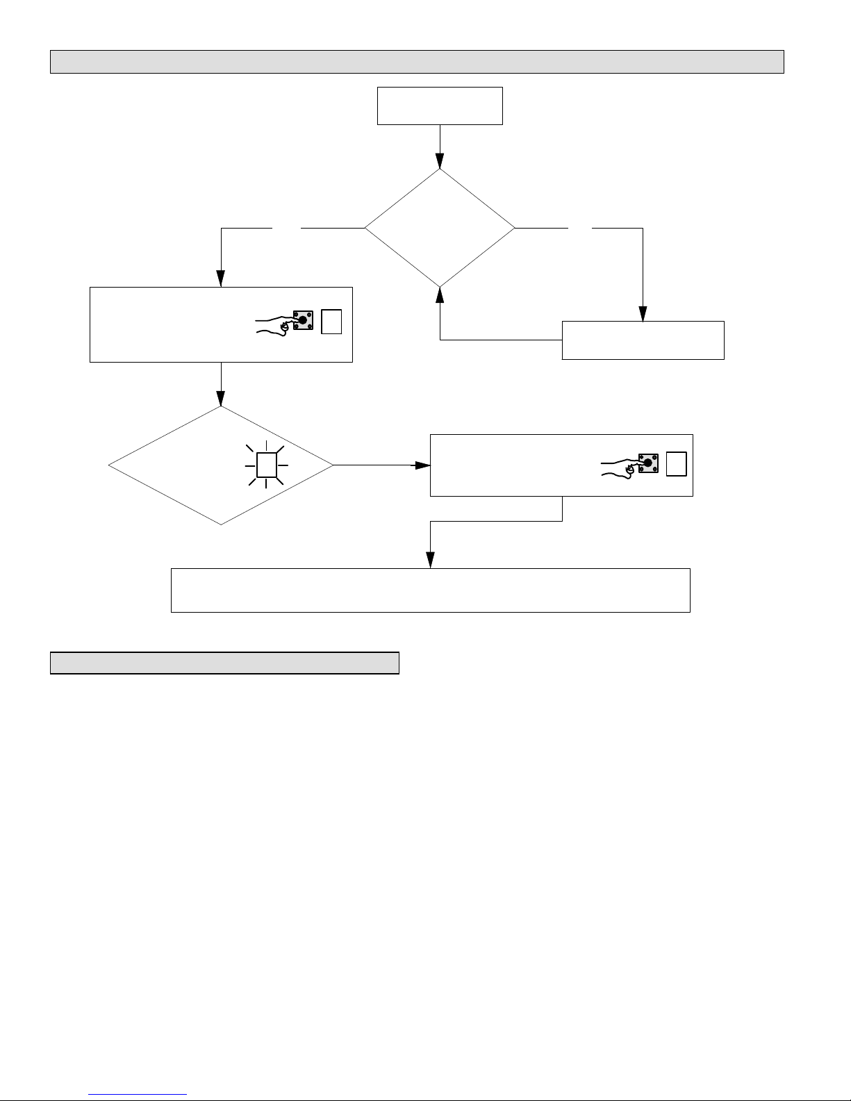
Indoor Blower Test
To indoor blower test mode, push
and hold button next to single
character LED display until
(Solid bar), then release button.
(Solid bar) starts blinking .
Indoor Blower Test Mode
AHC in Idle Mode
Ye s
(No heating cooling or indoor
fan operation)
No
Turn room thermostat to
Push and hold button until the
solid A symbol is displayed on the
single character LED display, then
release button.
OFF
Control will cycle the indoor blower motor for ten seconds at 70% of maximum air for selected capacity size unit.
Control will indoor blower test mode.
Checkout Procedures
NOTE − Refer to outdoor unit installation instructions for
system start−up instructions and refrigerant charging
instructions.
PRE-START-UP CHECKS
S Is the air handler properly and securely installed?
S If horizontally configured, is the unit sloped up to 1/4
inch toward drain lines?
S Will the unit be accessible for servicing?
S Has an auxiliary pan been provided under the unit with
separate drain for units installed above a finished
ceiling or in any installation where condensate
overflow could cause damage?
S Have ALL unused drain pan ports been properly
plugged?
S Has the condensate line been properly sized, run,
trapped, pitched, and tested?
S Is the duct system correctly sized, run, sealed, and
insulated?
S Have all cabinet openings and wiring been sealed?
S Is the indoor coil factory-installed TXV properly sized
for the outdoor unit being used?
S Have all unused parts and packaging been disposed
of?
S Is the filter clean, in place, and of adequate size?
S Is the wiring neat, correct, and in accordance with the
wiring diagram?
S Is the unit properly grounded and protected (fused)?
S Is the thermostat correctly wired and in a good
location?
S Are all access panels in place and secure?
CHECK BLOWER OPERATION
S Set thermostat to FAN ON.
S The indoor blower should come on.
CHECK COOLING OPERATION
S Set thermostat to force a call for cooling
(approximately 5ºF lower than the indoor ambient
temperature).
Page 36
Page 37
S The outdoor unit should come on immediately and the
indoor blower should start between 30 − 60 seconds
later.
S Check the airflow from a register to confirm that the
system is moving cooled air.
S Set the thermostat 5ºF higher than the indoor
temperature. The indoor blower and outdoor unit
should cycle off.
CHECK ELECTRIC HEATER (IF USED)
S Set thermostat to call for auxiliary heat (approximately
5°F above ambient temperature). The indoor blower
and auxiliary heat should come on together. Allow a
minimum of 3 minutes for all sequencers to cycle on.
S Set the thermostat so that it does not call for heat.
Allow up to 5 minutes for all sequencers to cycle off.
second heat sequencer can be connected with the first
sequencer to W1 on the thermostat. They may also be
connected to a second heating stage W2 on the thermostat
subbase.
EMERGENCY HEAT (HEATING HEAT PUMP)
If the selector switch on the thermostat is set to the
emergency heat position, the heat pump will be locked out
of the heating circuit, and all heating will be electric heat (if
applicable). A jumper should be placed between W2 and E
on the thermostat subbase so that the electric heat control
will transfer to the first-stage heat on the thermostat. This
will allow the indoor blower to cycle on and off with the
electric heat when the fan switch is in the AUTO position.
Maintenance
DEALER
Operation
COOLING (COOLING ONLY OR HEAT PUMP)
When the thermostat calls for cooling, 24 volts is put on the
blower time−delay relay coil. After a delay, the indoor
blower relay energizes. The normally open contacts close,
causing the indoor blower motor to operate. The circuit
between R and Y is completed, closing the circuit to the
contactor in the outdoor unit, starting the compressor and
outdoor fan motor.
On heat pumps, circuit R and O energizes the reversing
valve, switching the valve to the cooling position. (The
reversing valve remains energized as long as the
thermostat selector switch is in the COOL position.)
At the completion of the cooling demand and after the
relay’s time-delay, the compressor and outdoor fan will
cycle off.
HEATING (ELECTRIC HEAT ONLY)
When the thermostat calls for heat, the circuit between R
and W is completed, and the heat sequencer is energized.
A time delay follows before the heating elements and the
indoor blower motor come on. Units with a second heat
sequencer can be connected with the first sequencer to W
on the thermostat subbase, or they may also be connected
to a second stage on the subbase.
HEATING (HEAT PUMP)
When the thermostat calls for heating, 24 volts is put on the
blower time−delay relay coil. After a delay, the normally
open contacts close, causing the indoor blower motor to
operate. The circuit between R and Y is completed, closing
the circuit to the contactor in the outdoor unit, starting the
compressor and outdoor fan motor. Circuit R and G
energizes the blower relay, starting the indoor blower
motor.
If the room temperature should continue to fall, the circuit
between R and W1 is completed by the second-stage heat
room thermostat. Circuit R−W1 energizes a heat
sequencer. The completed circuit will energize
supplemental electric heat (if applicable). Units with a
WARNING
Electric shock hazard. Can cause injury
or death. Before attempting to perform
any service or maintenance, turn the
electrical power to unit OFF at disconnect
switch(es). Unit may have multiple power
supplies.
WARNING
Improper installation, adjustment, alteration, service or
maintenance can cause personal injury, loss of life, or
damage to property.
Installation and service must be performed by a licensed
professional installer (or equivalent) or a service agency.
Maintenance and service must be performed by a qualified
installer or service agency. At the beginning of each
cooling season, the system should be checked as follows:
Outdoor Unit
1. Outdoor unit fan motor is pre−lubricated and sealed.
No further lubrication is needed.
2. Visually inspect all connecting lines, joints and coils for
evidence of oil leaks.
3. Check all wiring for loose connections.
4. Check for correct voltage at unit (unit operating).
5. Check amp draw on outdoor fan motor.
Motor Nameplate:_________ Actual:__________.
6. Inspect drain holes in coil compartment base and
clean if necessary.
NOTE - If insufficient cooling occurs, the unit should be
gauged and refrigerant charge should be checked.
Outdoor Coil
Clean and inspect outdoor coil (may be flushed with a
water hose). Ensure power is off before cleaning.
NOTE It may be necessary to flush the outdoor coil
more frequently if it is exposed to substances which are
corrosive or which block airflow across the coil (e.g., pet
urine, cottonwood seeds, fertilizers, fluids that may contain
high levels of corrosive chemicals such as salts)
Page 37
CBX32MV SERIES
Page 38
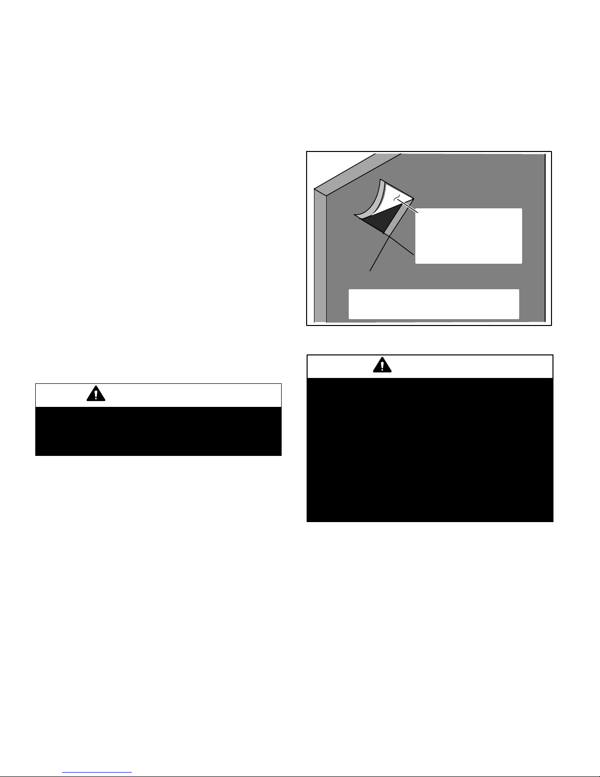
Sea Coast Moist air in ocean locations can carry salt,
which is corrosive to most metal. Units that are located
near the ocean require frequent inspections and
maintenance. These inspections will determine the
necessary need to wash the unit including the outdoor coil.
Consult your installing contractor for proper
intervals/procedures for your geographic area or service
contract.
Indoor Unit
1. Clean or change filters.
2. Lennox blower motors are prelubricated and
permanently sealed. No more lubrication is needed.
3. Adjust blower speed for cooling. Measure the pressure
drop over the coil to determine the correct blower CFM.
Refer to the unit information service manual for pressure
drop tables and procedure.
4. Belt Drive Blowers − Check belt for wear and proper
tension.
5. Check all wiring for loose connections.
6. Check for correct voltage at unit. (blower operating)
7. Check amp draw on blower motor.
Motor Nameplate:_________ Actual:__________.
Indoor Coil
1. Clean coil if necessary.
2. Check connecting lines, joints and coil for evidence of
oil leaks.
3. Check condensate line and clean if necessary.
Cabinet Insulation
IMPORTANT
DAMAGED INSULATION MUST BE REPAIRED OR
REPLACED before the unit is put back into operation. Insulation loses its insulating value when wet, damaged,
separated or torn.
Matt- or foil−faced insulation is installed in indoor
equipment to provide a barrier between outside air
conditions (surrounding ambient temperature and
humidity) and the varying conditions inside the unit. If the
insulation barrier is damaged (wet, ripped, torn or
separated from the cabinet walls), the surrounding
ambient air will affect the inside surface temperature of the
cabinet. The temperature/humidity difference between the
inside and outside of the cabinet can cause condensation
on the inside or outside of the cabinet which leads to sheet
metal corrosion and subsequently, component failure.
REPAIRING DAMAGED INSULATION
Areas of condensation on the cabinet surface are an
indication that the insulation is in need of repair.
If the insulation in need of repair is otherwise in good
condition, the insulation should be cut in an X pattern,
peeled open, glued with an appropriate all−purpose glue
and placed back against the cabinet surface, being careful
to not overly compress the insulation so the insulation can
retain its original thickness. If such repair is not possible,
replace the insulation. If using foil-faced insulation, any
cut, tear, or separations in the insulation surface must be
taped with a similar foil−faced tape.
GLUE −make sure there is
full coverage of glue on the
metal or insulation so there
are no areas where air
pockets may form which
can lead to sweating.
1. CUT INSULATION IN X PATTERN
2. APPLY GLUE
3. PRESS GLUED TABS AGAINST CABINET
Figure 27. Repairing Insulation
WARNING
Electric Shock Hazard.
Can cause injury or death.
Foil-faced insulation has conductive characteristics
similar to metal. Be sure there are no electrical
connections within a ½" of the insulation. If the foil-faced
insulation comes in contact with electrical voltage, the foil
could provide a path for current to pass through to the
outer metal cabinet. While the current produced may not
be enough to trip existing electrical safety devices (e.g.
fuses or circuit breakers), the current can be enough to
cause an electric shock hazard that could cause
personal injury or death.
HOMEOWNER
Cleaning of the outdoor unit’s coil should be performed by
a trained service technician. Contact your dealer and set
up a schedule (preferably twice a year, but at least once a
year) to inspect and service your outdoor unit. The
following maintenance may be performed by the
homeowner.
Page 38
Page 39

CAUTION
Physical contact with metal edges and corners while
applying excessive force or rapid motion can result in
personal injury. Be aware of, and use caution when
working near these areas during installation or while
servicing this equipment.
IMPORTANT
Sprinklers and soaker hoses should not be installed
where they could cause prolonged exposure to the
outdoor unit by treated water. Prolonged exposure of the
unit to treated water (i.e., sprinkler systems, soakers,
waste water, etc.) will corrode the surface of steel and
aluminum parts and diminish performance and longevity
of the unit.
Outdoor Coil
The outdoor unit must be properly maintained to ensure its
proper operation.
S Please contact your dealer to schedule proper
inspection and maintenance for your equipment.
S Make sure no obstructions restrict airflow to the
outdoor unit.
S Grass clippings, leaves, or shrubs crowding the unit
can cause the unit to work harder and use more
energy.
S Keep shrubbery trimmed away from the unit and
periodically check for debris which collects around the
unit.
Routine Maintenance
In order to ensure peak performance, your system must be
properly maintained. Clogged filters and blocked airflow
prevent your unit from operating at its most efficient level.
1. Air Filter Ask your Lennox dealer to show you
where your indoor unit’s filter is located. It will be either
at the indoor unit (installed internal or external to the
cabinet) or behind a return air grille in the wall or
ceiling. Check the filter monthly and clean or replace
it as needed.
2. Disposable Filter Disposable filters should be
replaced with a filter of the same type and size.
NOTE
If you are unsure about the filter required for your
system, call your Lennox dealer for assistance.
3. Reusable Filter Many indoor units are equipped
with reusable foam filters. Clean foam filters with a
mild soap and water solution; rinse thoroughly; allow
filter to dry completely before returning it to the unit or
grille.
NOTE
any time the unit is in operation.
The filter and all access panels must be in place
4. Electronic Air Cleaner Some systems are
equipped with an electronic air cleaner, designed to
remove airborne particles from the air passing through
the cleaner. If your system is so equipped, ask your
dealer for maintenance instructions.
5. Indoor Unit The indoor unit’s evaporator coil is
equipped with a drain pan to collect condensate
formed as your system removes humidity from the
inside air. Have your dealer show you the location of
the drain line and how to check for obstructions. (This
would also apply to an auxiliary drain, if installed.)
Thermostat Operation
See the ComfortSense® 7000 or icomfort Toucht
thermostat homeowner manual for instructions on how to
operate your thermostat.
Preservice Check
If your system fails to operate, check the following before
calling for service:
S Verify room thermostat settings are correct.
S Verify that all electrical disconnect switches are ON.
S Check for any blown fuses or tripped circuit breakers.
S Verify unit access panels are in place.
S Verify air filter is clean.
S If service is needed, locate and write down the unit
model number and have it handy before calling.
Accessories
For update−to−date information, see any of the following
publications:
S Lennox CBX32MV Engineering Handbook
S Lennox Product Catalog
S Lennox Price Book
Page 39
CBX32MV SERIES
 Loading...