

Page 1

©2018 Lennox Industries Inc.
Dallas, Texas, USA
V8MSBB04 Shown
THIS MANUAL MUST BE LEFT WITH THE
OWNER FOR FUTURE REFERENCE
These instructions are intended as a general guide and do
not supersede local codes in any way. Consult authorities
having jurisdiction before installation.
WARNING
Improper installation, adjustment, alteration, service or maintenance can cause property damage,
personal injury or loss of life.
Installation and service must be performed by a licensed professional HVAC installer, service agency
or the gas supplier.
Failure to follow safety warnings and these instructions exactly could result in property damage, dangerous operation, serious injury, or death.
Any additions, changes, or conversions required in
order for the appliance to satisfactorily meet the application needs must be made by a licensed professional HVAC installer (or equivalent) using factoryspecifi ed parts.
Do not use this system if any part has been under
water. A fl ood-damaged appliance is extremely dan-
gerous. Immediately call a licensed professional
HVAC service technician (or equivalent) to inspect
the system and to replace all controls and electrical
parts that have been wet, or to replace the system, if
deemed necessary.
WARNING
The Mode Selection Box is factory fi tted with Black
plastic caps over the fl are connection points. These
must be replaced with the supplied brass fl are nuts.
Under no circumstances can the plastic caps be used
as a permanent seal even when not all ports are used.
A suitable blanking device must be fi tted on all unused
ports.
INSTALLATION
INSTRUCTIONS
Mode Selection Box
VRF SYSTEMS
507453-05
05/2018
Shipping and Packing List
Check the components for shipping damage. If you fi nd
any damage, immediately contact the last carrier.
Package 1 of 1 contains the following:
1 - Assembled mode selection box
3 - Insulation sleeves for piping from outdoor unit
1 - 1” X ¾” condensate drain adaptor
1 to 6* - ⅜” to ¼” adaptors
1 to 6* - ⅝” to ½” adaptors
1 to 6* - ¼” brass fl are nuts
1 to 6* - ½” brass fl are nuts
1 to 6* - Gas pipe insulation sleeve(s)
1 to 6* - Liquid pipe insulation sleeves
*Quantity of these items depends on number of refrigerant
piping connection pairs.
Installation
Mode selection boxes V8MSBB01, V8MSBB02, V8MSBB03 and V8MSBB04 are used with VRA heat recovery
outdoor units to allow simultaneous heating and cooling in
multiple zones. Mode selection boxes are designed for indoor installation only.
Mode selection boxes include solenoid valves which control
refrigerant fl ow through the individual indoor units so that
unit operation (heating or cooling) matches the comfort requirements being sent by the occupant.
Mode selection boxes are sized to accommodate up to 24
indoor units. See Table 1.
Mode selection boxes are equipped with fl ared fi ttings for
indoor unit refrigerant piping connections and braze fi ttings
for outdoor unit connections.
Refer to the Product Specifi cation bulletin (EHB) for the
proper use of mode selection boxes with matching VRA
heat recovery units, indoor units, branch pipes, line sets
and controls.
CAUTION
As with any mechanical equipment, contact with sharp
sheet metal edges can result in personal injury. Take
care while handling this equipment and wear gloves and
protective clothing.
1
Page 2

CAUTION
To ensure proper system performance and reliability, Lennox does not recommend operation of VRF systems during any phase of construction. Construction debris, low
temperatures, harmful vapors, and operation of the unit
with misplaced fi lters can damage the units. Failure to
follow these guidelines will result in the warranty being
voided.
IMPORTANT
The Clean Air Act of 1990 bans the intentional venting
of refrigerant (CFC’s and HCFC’s) as of July 1, 1992.
Approved methods of recovery, recycling or reclaiming
must be followed. Fines and/or incarceration may be
levied for non-compliance.
System Piping
CAUTION
VRF system piping is customized for each installation.
The LVSS (Lennox VRF Selection Software) piping report
is an engineered design that must be followed. The piping
diagram or diagrams included within the LVSS report have
been prepared based on the information provided to the
Lennox VRF applications department.
When the indicated lengths change from the fi gures
stated within the report, it is imperative that prior to the
commencement of the refrigerant pipe work installation,
Lennox VRF applications department are informed of
these proposed changes.
Upon receipt of this new information the Lennox VRF
applications department will confi rm any changes that
may be applicable to this installation. If changes are
required, a new piping diagram will be produced and will
supersede all other previously provided documents.
Failure to provide this information regarding changes
to the original design may lead to insuffi cient capacity,
equipment failure, warranty being made void and the
refusal to commission the system.
2
Page 3

Unit Dimensions - inches (mm)
V8MSBB01, V8MSBB02, V8MSBB03, V8MSBB04
9
(229)
MOUNTING
LUGS (4)
11- 3/4
(298)
23-5/8
(600)
CONNECTIONS TO INDOOR UNITS
OUTDOOR UNIT
CONNECTIONS TO
CONDENSATE
DRAIN 1 (25) dia.
LOW
PRESSURE
GAS PIPE
TO OUTDOOR
UNIT
HIGH
PRESSURE
GAS PIPE
TO OUTDOOR
UNIT
LIQUID PIPE
TO OUTDOOR
UNIT
GAS
PIPE
LIQUID
PIPE
B
A
AB
Model No.
in. mm in. mm
V8MSBB01 24-3/4 629 19-1/4 489
V8MSBB02 24-3/4 629 19-1/4 489
V8MSBB03 37-3/4 959 32-1/4 819
V8MSBB04 37-3/4 959 32-1/4 819
Pipe Diameter - in.
Model No.
Low Pressure
Gas Pipe
Connections to Outdoor Unit Connections to Indoor Unit
High Pressure
Gas Pipe
Liquid
Pipe
1
Liquid Pipe
2
Gas Pipe
V8MSBB01 7/8 3/4 1/2 3/8 5/8
V8MSBB02 7/8 3/4 1/2 3/8 5/8
V8MSBB03 1-1/8 7/8 5/8 3/8 5/8
V8MSBB04 1-1/8 7/8 5/8 3/8 5/8
1
3/8 x 1/4 in. adaptor furnished for liquid pipe connection to outdoor unit (if required).
2
5/8 x 1/2 in. adaptor furnished for gas pipe connection to outdoor unit (if required).
3
Page 4

Installation Clearances - inches (mm)
CONCRETE CEILING
Minimum
11-7/8 (300) Minimum
2 (51)
SUSPENDED CEILING
Required! Suitably sized access
panel required to provide full
access to electrical panel
24
(610)
REFRIGERANT
PIPE
59 (1500)
Maximum
PIPE
HANGER
59 (1500)
Maximum
15-3/4
(400)
CONNECTIONS TO INDOOR UNITS
36
(914)
Minumum
Suitably sized access panel for gaining access to flare nuts or isolating
ball valves if mounted above a solid ceiling
OUTDOOR UNIT
CONNECTIONS TO
36
(914)
Minimum
Access panels are a requirement for system commissioning and future
preventative maintenance.
4
Page 5
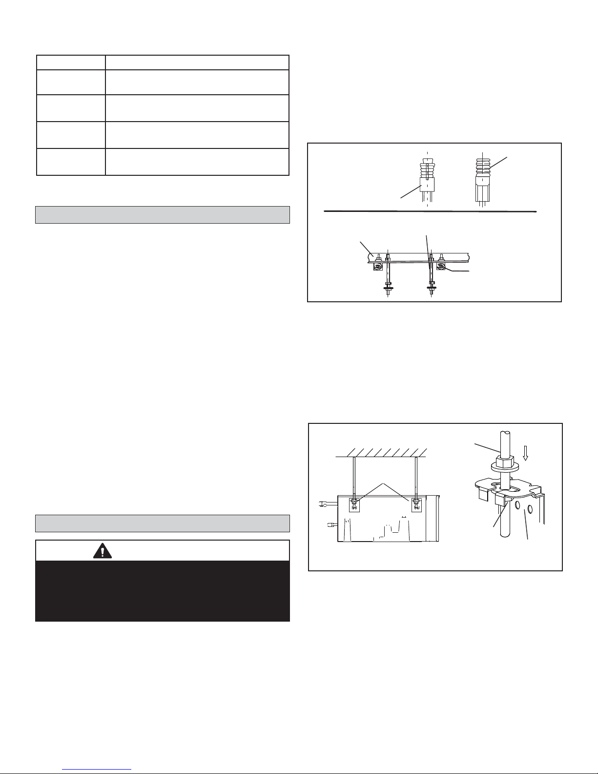
Table 1. Mode Selection Boxes
Model No. Application
V8MSBB01* 1 group, 1 indoor unit maximum
V8MSBB02
V8MSBB03
V8MSBB04
*Use with VHIA072 and VHIA096 only.
2 groups, 4 indoor units maximum per group,
8 indoor units maximum
4 groups, 4 indoor units maximum per group,
16 indoor units maximum
6 groups, 4 indoor units maximum per group
24 indoor units maximum
1. Make sure that the structural ceiling is able to support
the weight of the mode selection box(es). It may be
necessary to add extra support. If the structural ceiling
is constructed of concrete, install anchors to accept
four ⅜ inch threaded rods to suspend the mode
selection box. If the structural ceiling includes wooden
joists, use angle iron or a Unistrut channel fi xed
securely in place to accept the ⅜ inch threaded rods.
See Figure 1.
Ǫ´7+5($'(D
CONCRETE CEILING
USING ANCHORS
$1&+25
ROD
Mode Selection Box Location
Consider the following items when positioning the mode
selection box for installation:
• Sounds are made by refrigerant as solenoid valves
open and close inside the mode selection box. Do not
install the mode selection box where these sounds
may disturb building occupants.
• The mode selection box must be sloped 1/8” toward
condensate drain outlet.
• Provide suffi cient clearance around mode selection
box to allow 3 feet of straight pipe before the fi rst
elbow or branch pipe is installed. See Figure 3.
• If the unit is being installed in an application that
includes a sheet rock (plasterboard) ceiling, it is
required that an access panel be installed in a
suitable location. This will also allow access for
future maintenance (requirement of Lennox warranty
program).
Access is required during the commissioning process
to check the internal components, solenoid valves and
associated fl are nuts (See page 3), and to check the
local disconnect.
ANGLE IRON
BOLTED IN PLACE
ACROSS WOODEN JOISTS
Ǫ´7+5($'(D
ROD
ANGLE IRON
ACROSS
WOODEN JOISTS
WOODEN JOIST
Figure 1. Suspending Methods
NOTE - Threaded rod (requirement of Lennox
warranty program) is the ONLY acceptable method of
suspending the unit; do not use chains or straps.
2. Slide one nut and one washer onto each threaded rod.
Use electrical tape to keep the washer from failing off.
Position the nuts slightly above the fi nal resting place
of the four suspension brackets.
Ǫ´7+5($'('
STRUCTURAL CEILING
SUSPENSION
BRACKETS
52'
Mode Selection Box Installation
IMPORTANT
The Clean Air Act of 1990 bans the intentional venting
of refrigerant (CFC’s and HCFC’s) as of July 1, 1992.
Approved methods of recovery, recycling or reclaiming
must be followed. Fines and/or incarceration may be
levied for non-compliance.
Use the provided suspension brackets to suspend the
mode selection box(es) between the outdoor and indoor
units. The mode selection box location must be able to
accommodate the size of the box, as well as the required
3 feet of straight pipe length between the box and the fi rst
elbow or branch pipe. Refer to the dimension drawing on
Page 3 and Figure 3.
LEVELING NUT
72:$5'&21'(16$7('5$,1&211(&7,21
%2;08676/23(´
SUSPENSION
BRACKET
Figure 2. Suspension Hardware
3. Raise the mode selection box and insert the threaded
rods into the suspension brackets. Slide a washer
and then a nut onto each rod below each suspension
bracket. Use the leveling nut (beneath suspension
bracket) to adjust the mode selection box. Remove
the electrical tape holding the upper washers and nuts
in place and tighten each of the four nuts above the
brackets down onto the brackets. The mode selection
box must be sloped 1/8” toward condensate drain
outlet.
4. Continue with refrigerant piping connections.
5
Page 6

Refrigerant Piping Connections
WARNING
Refrigerant leaks are unlikely; however, if a refrigerant
leak occurs, open a door or windows to dilute the
refrigerant in the room. Turn off the unit and all other
appliances that may cause a spark. Call a licensed
professional HVAC technician (or equivalent) to repair
the leak.
Use only R410A refrigerant to charge this system. Use of
other refrigerant or gas will damage the equipment.
Do not allow air or other contaminants to enter system
during installation of refrigerant piping. Contaminants
will result in lower system capacity and abnormally high
operating pressures and may result in system failure or
explosion.
Insulate all refrigerant piping.
Refrigerant pipes may be very hot during unit operation.
Do not allow contact between wiring and bare copper
pipes.
After refrigerant piping connections have been
completed, check the system for leaks per
commissioning instructions.
WARNING
The Mode Selection Box is factory fi tted with Black
plastic caps over the fl are connection points. These
must be replaced with the supplied brass fl are nuts.
Under no circumstances can the plastic caps be used
as a permanent seal even when not all ports are used.
A suitable blanking device must be fi tted on all unused
ports.
IMPORTANT
Do not remove seals from refrigerant piping stubs until
connections are being made. This will prevent dust or
water from getting into the refrigerant piping before it is
connected.
From
Outdoor
Unit
To
Indoor
Unit
First Elbow or
Branch Pipe
Conection
>36”
>36”
MS
Box
Figure 3. Mode Selection Box Piping
6
Page 7

• Refrigerant piping connections from outdoor unit(s)
are made with fi eld-brazed connections. Field piping
connections for the outdoor unit gas pipes and liquid
pipe are provided on the right side of the mode
selection box.
• The four available mode selection boxes can
accommodate varying numbers of indoor units. See
Table 1 and Figure 4.
Outgoing gas and liquid connections for the indoor
units are on the front of the box. Connections to the
indoor units are made using the provided brass fl are
nuts. Adaptors are provided with the mode selection
box to accommodate the use of different pipe sizes.
Refer to the LVSS (Lennox VRF Selection Software)
piping report for pipe sizes.
• Refer to the VRA heat recovery unit installation
instructions and product specifi cations (EHB) bulletin
for more detailed information on refrigerant piping
connections.
Gas pipe O.D. (5/8” O.D.1)
• Field refrigerant piping for the VRA heat recovery units
includes a variety of branch pipe kits, mode selection
boxes and fi eld-provided piping.
Outdoor unit branch pipe kits are used to join multiple
outdoor units to reach the required system capacity.
Mode selection box branch pipe kits are available
to evenly split system capacity among the varying
numbers of mode selection boxes.
Indoor unit branch pipe kits split the system capacity
among up to four indoor units per connection from
each mode selection box. See mode selection box
branch pipe kits in Figure 8 and a typical VRA system
piping schematic in Figure 9.
• Allow a minimum of 3 feet between the mode selection
box and the fi rst elbow or branch pipe in refrigerant
piping. See Figure 3.
• After refrigerant piping has been installed and checked
for leaks, apply the provided insulation sleeves over all
connections.
Low-pressure gas pipe (7/8” O.D.)
Liquid pipe O.D. (3/8” O.D.
2
)
High-pressure gas pipe (3/4” O.D.)
Liquid pipe O.D. (1/2” O.D.)
Drain connection (1” O.D.3)
V8MSBB01*
V8MSBB02
* Use with VHIA072 and 096 only. Connective branch pipe kit included with indoor unit.
Gas pipe O.D. (5/8” O.D.1)
Liquid pipe O.D. (3/8” O.D.
2
)
Low-pressure gas pipe (1-1/8” O.D.)
High-pressure gas pipe (7/8” O.D.)
Liquid pipe (5/8” O.D.)
Drain connection (1” O.D.
V8MSBB03
Gas pipe O.D. (5/8” O.D.1)
Liquid pipe O.D. (3/8” O.D.
2
)
Low-pressure gas pipe (1-1/8” O.D.)
High-pressure gas pipe (7/8” O.D.)
Liquid pipe (5/8” O.D.)
Drain connection (1” O.D.3)
V8MSBB04
3
)
1
3/8 x 1/4 in. adaptor furnished for liquid pipe connection to indoor unit (if required).
2
5/8 x 1/2 in. adaptor furnished for gas pipe connection to indoor unit (if required).
3
1 inch x 3/4 in. condensate drain adaptor furnished for fi eld installation (if required).
Figure 4. Mode Selection Box Piping Connection Details
7
Page 8

All lines must be individually insulated.
1. The seal on the mode selection box refrigerant piping
connections should remain in place until the last
possible moment. This will prevent dust or water from
getting into the refrigerant piping before it is connected.
2. Remove the black plastic caps from the mode selection
box connections and discard.
3. Slide the fl are nuts onto the ends of the fi eld-provided
refrigerant piping before using a suitable fl aring tool to
fl are the end of the copper pipe.
4. Apply recommended R-410A refrigerant lubricant to the
outside of the fl ared refrigerant lines (Figure 5-A).
5. Align the threaded connections with the fl ared refrigerant
lines. Tighten the fl are nuts lightly at fi rst to obtain a
smooth match (Figure 5-B).
Table 2. Refrigerant Piping Connections
(Up to a maximum of 32 ft. only)
Size
(Btuh)
7000
12000
15000
18000
24000
30000
36000
48000
Liquid Line
in.
1/4 1/2
3/8 5/8
Vapor Line
in.
Always refer to the provided piping diagram for correct piping sizes. Contact Lennox VRF Application support for assistance with piping sizing or an updated piping diagram.
NOTE - 5/8” and 3/8” fl are nuts are part of the reducing
adapters. Cut the reducing adapters to release the 5/8”
and 3/8” fl are nuts.
A
CANT ON THE OUTSIDE OF
THE FLARE
MALE FLARE
CONNECTION
B
Figure 5. Making Connections
(Male to Female Connection)
6. Then, use two wrenches to continue to tighten the nuts
without twisting the pipes. Once snug, continue another
half-turn on each nut which should create a leak-free
joint. A torque wrench may be used to tighten fl are
nuts using table 3 recommendations. See Figure 6. Do
not over-tighten a fl ared joint. Flared connections
should always be accessible and must be insulated
to prevent condensation.
7. After refrigerant piping has been installed and checked
for leaks, apply insulation over the piping and all fl are
connections.
IMPORTANT
Always use two wrenches when tightening fl are nuts to
avoid twisting refrigerant piping. DO NOT over-tighten
fl are nuts.
Torque
To
Mode
Selection
Box
Wrench
Backup
Wrench
To Indoor Unit
Figure 6. Tighten Flare Nut
8
Page 9

Table 3. Flare Nut Torque Recommendations
Outside
Diameter
Inches U.S.
1/4” 15 ft.-lb. 1/4 turn
3/8” 26 ft.-lb. 1/2 turn
1/2” 41 ft.-lb. 7/8 turn
5/8” 48 ft.-lb. 1 full turn
Flare nuts may need further tightening. Check ALL system
fl are nut connections during pressure testing process.
Recommended
Torque
No torque wrench
available
Finger tighten and
use an appropriately
sized wrench to turn an
additional:
Table 4. Piping Connection Information
IMPORTANT!
Flared connections should always be accessible and must be insulated to prevent condensation. See Figure 7.
Insulate ALL flared connections
to prevent condensation.
MS Box
Figure 7. Insulate Flared Connections
Indoor Unit
Indoor Unit
Capacity BTUs
7,000 1/2 x 1/4 1/2 x 1/4
9,000 1/2 x 1/4 1/2 x 1/4
12,000 1/2 x 1/4 1/2 x 1/4
15,000 1/2 x 1/4 1/2 x 1/4
18,000 5/8 x 3/8 5/8 x 3/8 No 3/4 x 1/2
24,000 5/8 x 3/8 5/8 x 3/8 No 3/4 x 1/2
30,000 5/8 x 3/8 5/8 x 3/8 No 3/4 x 1/2
36,000 5/8 x 3/8 5/8 x 3/8 No 3/4 x 1/2
48,000 5/8 x 3/8 5/8 x 3/8 No 3/4 x 1/2
54,000 5/8 x 3/8 5/8 x 3/8 No 3/4 x 1/2
NOTE - For VHIA072/096 indoor units, refer to the VHIA
installation manual and system piping diagram for correct
pipe sizes.
NOTE - All VVCA units have brazed connections. Piping
length rules still apply.
Factory Flare
Connection
Sizes Gas/Liquid
Piping Length
From MS Box
to Indoor Unit Is
equal to or less
than 32 ft.
Adaptor
Required for
Connection to
MS Box
Yes -Factory
Supplied
Yes -Factory
Supplied
Yes -Factory
Supplied
Yes -Factory
Supplied
It is imperative that the system piping is installed per the
LVSS (Lennox VRF Selection Software) piping report! If
the measurements on the Lennox VRF piping diagram
do not match the anticipated fi eld measurements, contact
Lennox VRF Application Support before beginning piping
installation.
Piping Length
from MS Box to
Indoor Unit is
greater than 32
ft.
5/8 x 3/8 No
5/8 x 3/8 No
5/8 x 3/8 No
5/8 x 3/8 No
Required for
Connection to
IMPORTANT
Adaptor
MS Box
Yes -Field
Supplied
Yes -Field
Supplied
Yes -Field
Supplied
Yes -Field
Supplied
Yes -Field
Supplied
Yes -Field
Supplied
9
Page 10

Material
Insulation
(furnished)
ID:1/4
OD:3/8
ID:3/8
ID:1/2
ID:5/8
Adapter Pipe - Inch
ID:1/2
OD:5/8
ID:3/8
OD:1/2
OD:3/4
(3 sets)
Liquid
side used
side used
High-pressure
side used
Low-pressure
ID:3/8
ID:1/2
OD:1/2
(3 sets)
ID:1/2
ID:5/8
ID:3/4
ID:5/8
OD:5/8
OD:3/4
(3 sets)
(Liquid side used)
ID:7/8
ID:3/4
OD:3/4
(3 sets)
ID:3/4
(3 sets)
OD:7/8
(Liquid side used)
ID:1
ID:7/8
OD:7/8
ID:3/8
OD:3/8
ID:1/4
ID:5/8
OD:5/8
(ID:1/2)
ID:3/8
ID:3/4
ID:5/8
OD:5/8
ID:5/8
ID:3/4
OD:3/4
OD:3/8
ID:3/8
ID:1/4
OD:5/8
(ID:1/2)
ID:3/8
ID:1/4
ID:3/4
OD:3/4
(ID:5/8)
ID:1/2
ID:1/2
OD:1/2
ID:3/8
ID:1/4
ID:5/8
ID:3/4
OD:3/4
ID:1
ID:7/8
OD:7/8
OD:1/2
ID:3/8
ID:1/4
OD:3/4
ID:1/2
(ID:5/8)
ID:5/8
OD:5/8
(ID:1/2)
ID:3/8
ID:7/8
OD:7/8
(ID:3/4)
ID:5/8
ID:1
ID:7/8
OD:7/8
ID:1-1/4
ID:1-1/8
OD:1-1/8
OD:5/8
ID:3/8
ID:1/4
OD:7/8
ID:5/8
ID:1/2
(ID:1/2)
(ID:3/4)
ID:3/4
OD:3/4
(ID:5/8)
ID:1/2
ID:1-1/8
OD:1-1/8
ID:7/8
ID:3/4
ID:1-1/4
ID:1-1/8
OD:1-1/8
ID:1-1/2
ID:1-3/8
OD:1-3/8
OD:3/4
(ID:5/8)
ID:1/2
ID:3/8
OD:1-1/8
ID:7/8
ID:3/4
ID:5/8
ID:7/8
OD:7/8
(ID:3/4)
ID:5/8
ID:1-3/8
OD:1-3/8
ID:1-1/8
ID:7/8
OD:7/8
(ID:3/4)
ID:5/8
ID:1/2
ID:1-1/2
ID:1-3/8
OD:1-3/8
OD:1-3/8
ID:1-1/8
ID:7/8
ID:3/4
ID:1-3/4
ID:1-5/8
OD:1-5/8
ID:3/4
OD:3/4
(ID:5/8)
ID:1/2
OD:3/4
(ID:5/8)
ID:1/2
Low-Pressure Gas Side Joints - Inch High-Pressure Gas Side Joints - Inch Liquid Side Joints - Inch
Name
V8MSBP01
Locate fi rst branch pipe kit of system centrally to ensure
even distribution of refrigerant.
Figure 8. Mode Selection Box Branch Pipe Kits
OD:7/8
(ID:3/4)
ID:5/8
ID:1/2
ID:1-1/8
OD:1-1/8
ID:7/8
ID:3/4
ID:7/8
OD:7/8
(ID:3/4)
ID:5/8
V8MSBP02
IMPORTANT
10
OD:1-1/8
ID:7/8
ID:3/4
ID:5/8
V8MSBP03
ID:1-3/8
OD:1-3/8
ID:1-1/8
ID:7/8
OD:1-3/8
ID:1-1/8
ID:7/8
ID:3/4
V8MSBP04
ID:1-3/4
ID:1-5/8
ID:1-3/8
ID:1-5/8
ID:1-3/8
V8MSBP05
Page 11

(96) (120) (120)
g3 g2 g1
0
LEGEND
Branch Pipe
Mode Selection
Box (MS)
Indoor Unit
G1
NOTE - Indoor and outdoor unit
capacities are shown in parenthesis
L2
/
L1
A
b
a
Ė
c
MS1
L3
B
L4
C
L6
L5
MS3
MS2
d
N1
(024)
N2
(024)
e
L7
N4
(009)
N3
(048)
D
g
Ę
N8
(009)
N5
(048)
h
ė
i
mn
(018)
L9L8
f
MS4
L10
E
L11
MS7
r
N13
(018)
q
N12
(048)
p
N11
(048)
F
MS6
j
L12
L13
ę
MS5
k
l
N9
N6
(024)
N7
(024)
N10
(018)
PIPE AND COMPONENT NAMES
Name Designation
Outdoor Unit Connection Pipe g1, g2, g3, G1
Outdoor Unit Branch Pipe Assembly L, M
Main Pipe L1
Indoor Unit Main Pipe L2, L3, L4, L5, L6, L7, L8, L9, L10, L11, L12, L13
Branch Pipe Assembly between Main Pipe and Mode Selection Box (MS) A, B, C, D, E, F
Mode Selection Box (MS) MS1, MS2, MS3, etc.
Branch Pipe Assembly between Mode Selection Box (MS) and Indoor Unit I, II, III, IV
Indoor Unit auxiliary pipe between Mode Selection Box (MS) and downstream
Branch Pipe joint
Indoor Unit auxiliary pipe from Indoor Unit to the nearest Branch Pipe joint or
direct connected Mode Selection Box (MS)
Indoor Unit N1, N2, N3, etc.
a, g, j, k
b, c, d, e, f, h, i, l, m, n, p, q, r
Figure 9. Typical Piping Diagram
11
Page 12

Branch Pipe Kit Placement
Provide 24 inches to 36 inches of straight pipe before
and after each branch pipe kit to avoid creating refrigerant turbulence and fl ash points. Failure to follow 24
inch minimum guideline can lead to reduced capacity
and equipment damage. See Figure 7.
To Indoor Unit
CAUTION
24 inches minimum straight pipe required before and after
branch pipe kit to prevent capacity loss and equipment
damage.
From MS Box or
Previous Indoor
Unit
24” REQUIRED
36” PREFERRED
FIRST ELBOW OR
BRANCH PIPE
24” REQUIRED
CONNECTION
36” PREFERRED
To Indoor Unit
Top View
Branch pipe kits MUST be installed horizontal +/- 10°
NOTE - A maximum of four indoor units can be connected to one port on the Mode Selection Box. The combined maximum capacity of all indoor units connected to one port on a Mode Selection Box must not exceed 54,000 BTUs.
Insulation
Name Gas Side Joints (inch) Liquid Side Joints (inch)
,'
,'
2'
,'
2'
,'
,'
,'
2'
,'
V8IDBP01
,'
,'
2'
,'
2'
,'
2'
,'
Material
(furnished)
(2 sets)
OPERATION NOTE — All indoor units within a group
(units connected to a single piping connector on the mode
selection box) must operate in the same mode at all times.
Figure 10. Inches of Straight Pipe Before and After Branch Pipe Kit
IMPORTANT
12
Page 13

Condensate Drain Connection
A 1 inch OD condensate drain connection is provided
on the mode selection box. Route condensate piping to
a suitable drain per best practices, taking care to slope
the drain properly to ensure drainage. A 1 inch to ¾ inch
adaptor is provided if ¾ inch condensate pipe is preferred.
Mode Selection Box Wiring Connections
WARNING
Isolate the power supply before accessing unit electrical
terminals.
Install unit so that unit disconnect is accessible.
Follow all local and national codes, as well as this
installation instruction, during installation. Do NOT
overload electrical circuit, as this may lead to failure and
possible fi re.
Use specifi ed wiring and cable to make electrical
connections. Clamp cables securely and make sure that
connections are tight to avoid strain on wiring. Insecure
wiring connections may result in equipment failure and
risk of fi re.
Wiring must be installed so that all cover plates can be
securely closed.
This unit must be properly grounded and protected by a
circuit breaker. The ground wire for the unit must not be
connected to a gas or water pipe, a lightning conductor or
a telephone ground wire.
Do not connect power wires to the outdoor unit until all
other wiring and piping connections have been completed.
The mode selection box must be sloped 1/8” toward drain
outlet.
In the U.S.A., wiring must conform with current local codes
and the current National Electric Code (NEC). In Canada,
wiring must conform with current local codes and the current
Canadian Electrical Code (CEC).
Refer to unit nameplate for minimum circuit ampacity and
maximum overcurrent protection size.
NOTE - Three-conductor shielded cable must be used for
the communication wiring. This is necessary to ensure
proper system communication and operation.
Remove the cover panel from the mode selection box and
locate the terminal strip.
Connect properly sized power wiring and three-conductor
shielded cable as shown.
Indoor units and mode selection boxes on the same
refrigeration circuit should have a common power supply
but must have an independent disconnect switch installed
adjacent to the mode selection box for servicing and
maintenance purposes. Indoor unit and mode selection
box power supply MUST not be taken from the outdoor
unit. Always follow NEC/CEC and Local Codes.
13
Page 14

Power DistribuƟon Box
L1/L2
L1/L2
L1/L2
MS
Box
L1/L2/L3
PQE
PQE
PQE
PQE
PQE
PQE
L1/L2/L3
L1/L2/L3
L1/L2
L1/L2
PQE
L1/L2
L1/L2
L1/L2
L1/L2
PQE
MS
PQE
L1/L2
Box
L1/L2
PQE
L1/L2
PQE
Legend
PQE CommunicaƟon wiring
L1/L2 Single-Phase power wiring
L1/L2/L3 Three-Phase power wiring
Electrical disconnect switch
Figure 11. Typical Power Wiring Diagram (VRF Heat Recovery System Shown)
14
Page 15

NOTE - Each communication wire from the mode selection box should follow the refrigerant piping for that port.
Figure 12. Typical Communication Wiring Diagram (VRF Heat Recovery System)
15
Page 16

TRANS
EXVA
L1 L2
208-230V
M-O
CN10
Y/G
T2C1 T2C2
YEIIOW
TO OUTDOOR
To other MS boxes on
same refrigeration circuit.
GRAY
M-I
CN13
RED
BLACK
PQEPQE
TO INDOOR
BROWN
BLACK
2# MS UNIT
1# MS UNIT
S1
O N
1 2
REFRIGERANT PIPING
COMMUNICATIONS CABLE
Figure 13. V8MSBB01 Connections
VHIA072 and VHIA096 Only
OUTDOOR
UNIT
(P Q E)
INDOOR
UNIT
(P Q E)
NOTE - Use 3-conductor, shielded cable
for communication wiring.
NOTE - Indoor c
ommunications cable
must match indoor piping connections.
1# MS UNIT
gnituoR elbaC snoitacinummoC dna gnipiPsnoitcennoC gniriW
TRANS
EXVA
L2
L1
208-230V
2# MS UNIT
2
1
1# MS UNIT
2
1
M-O
M-I
CN13
Y/G
T2C1 T2C2
BLUE
WHITE
PQE PQE PQE
BLACK
ORANGE
YELLOW
BLACK
YEIIOW
BLACK
GRAY
INDOOR UNIT
INDOOR UNIT
(P Q E)
(P Q E)
(P Q E)
OUTDOOR UNIT
1# MS UNIT
06í,1'22R
NO.2 NO.1
MSíOUTDOOR
NOTE - Use 3-conductor, shielded cable
for communication wiring.
NOTE - Indoor c
ommunications cable
must match indoor piping connections.
gnituoR elbaC snoitacinummoC dna gnipiPsnoitcennoC gniriW
To other
MS boxes
on same
REFRIGERANT PIPING
COMMUNICATIONS CABLE
refrigeration
circuit.
Figure 14. V8MSBB02 Connections
16
Page 17

TRANS1
Wiring Connections
TRANS2
L2
L1
POWER IN
208-230V
RED
Y/G
2# MS UNIT
123456
1# MS UNIT
1234 56
BLUE
BLUE
WHITE
M-I(5, 6)
BLACK
YEIIOW
BLACK
ORANGE
T4C T4C1
PURPLE
GRAY
BLACK
ORANGE
GREEN
M-I(1~4)
BLACK
PQEPQE PQEPQE
TO INDOOR 6
TO INDOOR 5
TO INDOOR 4
TO INDOOR 3
Piping and Communications Cable Routing
(P Q E)
OUTDOOR
UNIT
NO.6
NO.5
M-O
BLUE
WHITE
BLACK
RED
BROWN
BLACK
PQE PQE
TO INDOOR 2
NO.4
TO INDOOR 1
1# MS UNIT
MS-INDOOR MS-OUTDOOR
NO.3 NO.2 NO.1
EXVA
YEIIOW
GRAY
BLACK
PQE
TO OUTDOOR
To other MS boxes on
same refrigeration circuit.
INDOOR UNIT
INDOOR UNIT
(P Q E)
REFRIGERANT PIPING
COMMUNICATIONS CABLE
Figure 15. V8MSBB03 and V8MSBB04 Connections
Network Address and Commissioning
After the system has been installed, use the system
remote control to assign a separate address for each of
the indoor units as part of the commissioning procedure.
INDOOR UNIT
(P Q E)
(P Q E)
INDOOR UNIT
(P Q E)
INDOOR UNIT
(P Q E)
INDOOR UNIT
(P Q E)
NOTE - Use 3-conductor, shielded cable for communication wiring.
NOTE - Indoor c
ommunications cable must match indoor piping connections.
Mode selection boxes do not require an address; however,
each indoor unit connected to the mode selection box
must be assigned an individual address.
17
Page 18

V8MBB01 Piping and Wiring Connection to VHIA072 or 096
Refrigerant Piping
• Use the provided branch pipe kit to connect both sets
of refrigerant line connections.
• Locate branch pipes no more than 32 feet from indoor
unit.
See piping report
for pipe sizes
• Piping between branch pipe and indoor unit: liquid line
= 3/8” and gas line = 5/8“.
• Consult LVSS piping report diagram for all other piping
sizes.
VHIA072/096V8MBB01
Gas branch pipe
(Provided with Mode
Selection Box)
Gas branch pipe
(Provided with VHIA unit)
5/8”
3/8”
Liquid branch pipe
(Provided with Mode
Selection Box)
Liquid branch pipe
(Provided with VHIA unit)
32’ maximum distance
between branch pipes and indoor unit
Top view of piping. Branch pipe kits MUST be installed level +/- 10°.
Figure 16. Piping for VHIA072 or 096 when V8MSBB01 is Greater Than 15 ft. (4.5 m) Away - VRA Heat Recovery
V8MBB01
VHIA072/096
Figure 17. Piping for VHIA072 or 096 when V8MSBB01 is Equal To or Less Than 15 ft. (4.5 m) Away - VRA Heat
5/8”
3/8”
Recovery
18
Page 19

Connect these
two pipes as
shown in “A”
below.
A
Incoming
liquid line
connection
Incoming
suction line
connection
Incoming
suction line
connection
Incoming
liquid line
connection
Connect these two
pipes as shown in
“A” left.
Figure 18. VHIA072 and 096 Refrigerant Connections
System Communication Wiring
• Connect PQE wiring to Board A of the VHIA072 or 096
Indoor unit.
Terminal Block A
PQE
Figure 19. VHIA072 and 096 Communication Terminal Block
Terminal Block B
PQE
19
Page 20

Troubleshooting
LED Lamp Defi nitions
LED Lamp Normally ON Slow Flash Flash
LED 1 Outdoor unit ON Outdoor unit standby Outdoor unit communication error
LED 2 Indoor unit ON of this MS Indoor unit OFF this MS Indoor unit communication error
Operation Mode References
0 OFF
2 COOLING MODE
3 HEATING MODE
4 FORCED COOLING MODE
5 MAIN COOLING MODE
6 MAIN HEATING MODE
20
Page 21

Spot Check
No. Description
1 Indoor unit quantity under the port
2 Operation mode under the port
3 Subcool inlet temperature
4 Superheated outlet temperature
T2 average of the system if operation mode is heating under
5
the port.
T2B average of the system if operation mode is cooling under
the port
T2 average of indoor units under the port if operation mode is
6
heating under the port.
T2B average of indoor units under the port if operation mode is
cooling under the port
7
Indoor unit quantity in the system which operate the same
mode as the port.
8 System operation mode
9 Sub cool EXV Pulse Position
10 Indoor unit quantity under the port which are ON.
11 Software version
12 End
Notes
When actual temp. ≤-9°, show -9; When indoor unit is OFF or operating Fan mode, show
-9 (means invalid value)
Figure 16. Spot Check
LED display (all ports)
Port 1
Port 2Port 3Port 4Port 5Port 6
Spot check
button
(one per port)
21
Page 22

Technical Support
1-844-GET-VRF1
(1-844-438-8731)
vrftechsupport@lennoxind.com
www.LennoxVRF.com
Download the app
from the Apple App Store or the Google Play store.
22
 Loading...