

Page 1
1
©2017 Lennox Industries Inc.
Dallas, Texas, USA
INSTALLATION/
OPERATION
INSTRUCTIONS
CONTROLS
507596-04
04/2017
THIS MANUAL MUST BE LEFT WITH
THE OWNER FOR FUTURE REFERENCE
WARNING
Improper installation, adjustment,
alteration, service or maintenance
can cause property damage, personal
injury or loss of life.
Installation and service must be
performed by a licensed professional
HVAC installer (or equivalent) or
service agency.
Frequent changes to operating mode
may cause system malfunction.
Allow at least one minute between
mode changes to allow the system to
stabilize.
IMPORTANT!
!
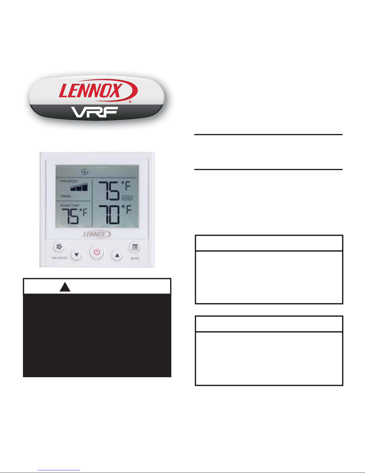
V0STAT54P-2 Indoor Unit
Non-programmable Controller
Electrostatic discharge can affect electronic components. Take precautions
to neutralize electrostatic charge by
touching your hand and tools to metal
prior to handling the control.
IMPORTANT!
Page 2
2
Shipping and Packing List
Package 1 of 1 contains;
1 – Wired Controller
1 – Installation and operation manual
2 – Plastic spacers
General
The V0STAT54P-2 is a wired non-programmable local controller that controls up to 16
VRF indoor units. These instructions are
intended as a general guide and do not supersede local codes in any way. Consult authorities having jurisdiction before installation.
Requirements
• Four-conductor cable is required for installation.
• Be sure that power supply has been
turned off before beginning installation.
• This controller should be used only as described in this manual.
• Do not install the controller on outside
walls (where there is unconditioned space
on opposite side of wall) or in locations
where direct sunlight may be present.
Installation
Clean controller using a clean, damp
cloth. Do not spray cleanser on or
around controller.
Do not install controller in areas
where harmful gases containing
sulfur or other damaging agents
may exist or the controller may be
damaged.
CAUTION
!
CAUTION
!
Power wiring between controller and fi rst
indoor unit:
• Minimum 18 AWG stranded shielded
cable up to 164 feet (50 m).
• Ensure there are no gaps between the
controller back cover and the mounting
surface.
• Fill any holes in the wall behind the
controller to avoid false readings from
infi ltration.
• Ground the shielded control wiring.
• Do not use a megger to test insulation.
Communication wiring between indoor
units:
• Minimum 18 AWG stranded shielded
cable.
Page 3
3
Do not operate controller with wet
hands.
CAUTION
!
Read all of the information in this manual
before using this controller. All wiring must
conform to local and national building and
electrical codes and ordinances. This is
a 12 VDC controller. Do not install on
voltages higher than 12 VDC.
• This manual provides the installation
instructions for this controller. Refer to the
included wiring diagrams to connect the
controller to the indoor unit.
• The controller uses low voltage. Keep a
minimum distance of 12” (305 mm) between low voltage control wire and high
voltage power wires.
IMPORTANT!
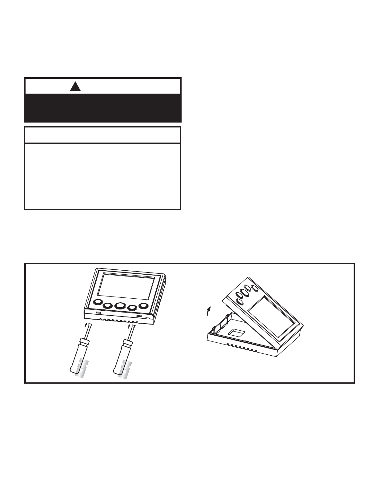
Figure 1. Remove Controller from Back Cover
1. Remove the controller from the back cover using a fl at head screw driver as shown. See
fi gure 1.
Page 4
4
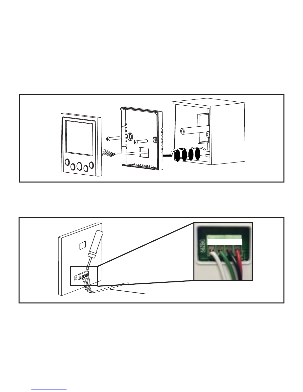
Figure 2. Installation
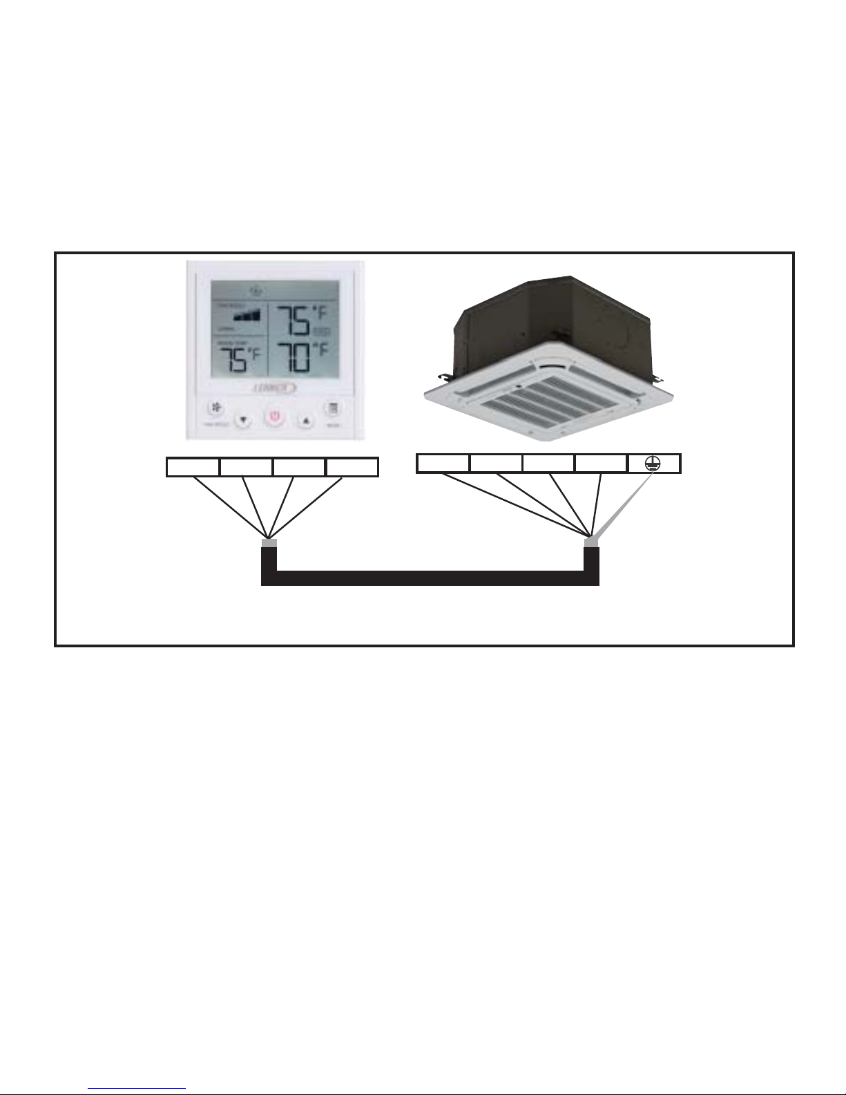
4. At the controller, wire the fi eld-provided 4-conductor shielded cable to X / Y / GND / 12V
terminal of the controller. See fi gure 3.
2. Adjust the length of the two plastic spacers as needed to allow the controller to be mounted
fl ush with the wall. NOTE – Be sure to provide for future maintenance by allowing enough
slack in the wiring to allow the controller to be removed from the wall if needed. See fi gure 2.
3. Attach the back cover using fi eld-provided screws.
Figure 3. Connection at Controller
4-conductor wiring
X 12VY GND
Page 5
5
Figure 4. Wire to One Indoor Unit
5. Reattach the controller to the back cover.
6. Connect the controller to one or more indoor units, up to 16. Use 4-conductor shielded cable
to connect to the fi rst indoor unit. NOTE - Wiring is polarity sensitive. See fi gure 4.
COM 12VX Y
12V X Y E
NOTE - Connect up to 16 indoor units
NOTE - Ground cable shielding at indoor unit
Page 6
6
Specifi cations
Input voltage 12 VDC
Ambient temperature 23~110°F (-5~43°C)
Ambient humidity RH40%~RH90%
Table 1. Specifi cations
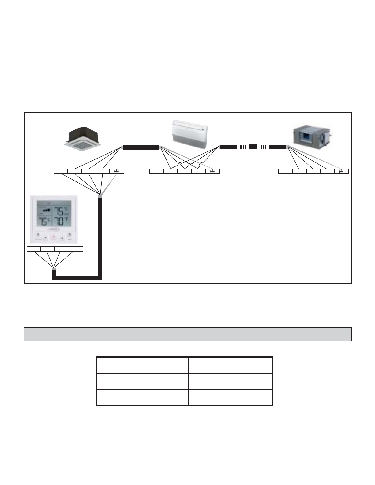
Figure 5. Wire Multiple Indoor Units
COM 12VX Y
12V X Y E 12V X Y E 12V X Y E
NOTE - Connect up to 16 indoor units
NOTE - Ground cable shielding at one end of each length of cable
7. Daisy chain 3-conductor control wiring to each additional indoor unit using the X Y E terminals in the electrical control box of the indoor unit. Do not daisy chain 12V power cable. See
fi gure 5. NOTE - Wiring is polarity sensitive.
Page 7

7
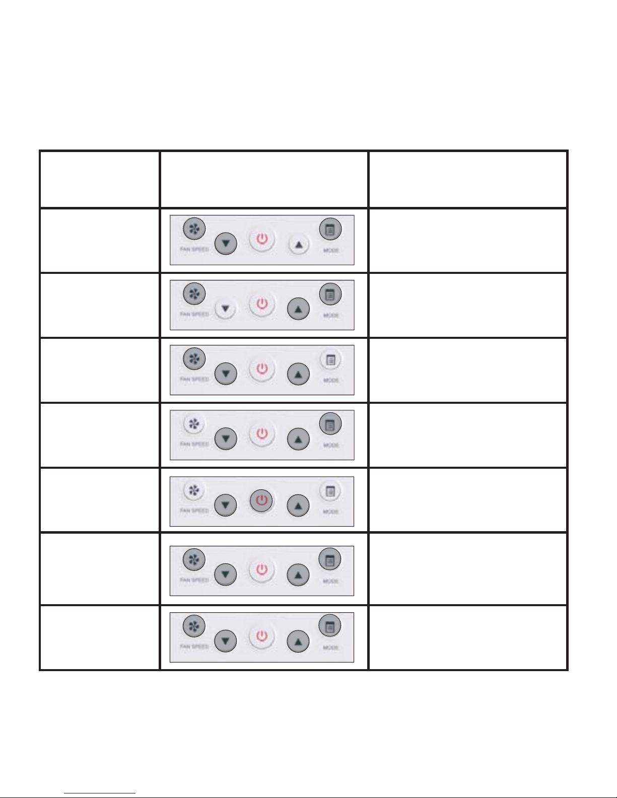
Description of Buttons
Power
Button
Fan
Speed
Button
Up-Arrow
Button
Mode
Button
Cooling
Mode
Heating
Mode
Auto
Mode
Dry
Mode
Fan
Mode
Locked
Function
Centralized
Controller
Locked
Cooling
Setpoint
Heating
Setpoint
Down-Arrow
Button
Room
Temperature
Swing
Fan Speed
Page 8

8
Operation
After powering on the controller, wait 30 seconds for initialization The indoor unit cannot
be controlled by the controller until initialization is complete.
Start/Stop Operation
Press the power button.
• Controller ON: LED display lit.
• Controller OFF: LED display not lit.
Set Operation Mode
Press the Mode button to scroll through the
mode selections.
• Cool – System operates in cooling mode.
• Heat – System operates in heating mode.
• Auto -- System operates in auto mode.
• Dry -- System operates in dehumidifi ca-
tion mode. NOTE - fan speed cannot be
adjusted during dry mode.
• Fan – Fan only, no heating or cooling.
To set (or change) the room temperature
setting (setpoint)
Press the up-arrow & down-arrow buttons to
adjust the setpoint.
When in Auto mode, separate heating and
cooling setpoints can be set. Press the Mode
button to switch between heating and cooling
setpoints.
NOTE - Indoor units connected to a local controller may also be controlled by a centralized
controller. Indoor units respond to the last
command sent. It is recommended that indoor units be controlled from a single source
of control, either local controller or centralized controller but not both, to avoid confl icts
in commands.
Page 9

9
MODEFAN SPEED
FAN SPEED
COOL
HEAT
ROOM TEMP.
Figure 6. Function Lock Indicator
Function Lock
Indicator
Louver Swing Operation
Press both the up-arrow button and the downarrow button simultaneously to start louver
auto swing operation. The louvers will move
automatically until stopped.
Press both the up-arrow button and the
down-arrow button simultaneously again
to stop the swing operation. The louvers
will remain in position where stopped. Do
not move louvers manually; only move
louvers using the auto swing function.
NOTE - Not available on all indoor unit types.
Lock Operation
Some operational functions can be locked.
See table 2
Page 10
10
Lock Type Operation
Simultaneously press the buttons
shown below
User Experience
Lock operation
mode
The Mode button is inactive.
User cannot change operation
mode using this controller.
Lock fan speed
The fan speed button is inactive. User cannot change fan
speed using this controller.
Lock temperature
increase
The Up-arrow button is inactive.
User cannot raise setpoint using this controller.
Lock temperature
decrease
The Down-arrow button is inactive. User cannot lower setpoint
using this controller.
Lock ON/OFF
status
The Power button is inactive
User cannot turn the indoor unit
on or off using this controller.
Lock all buttons
All buttons are inactive. User
cannot make any changes
to the indoor unit using this
controller.
Unlock all buttons
All buttons are active. User
can make any changes to the
indoor unit using this controller.
Table 2. Lock Operation Functions
Page 11
11
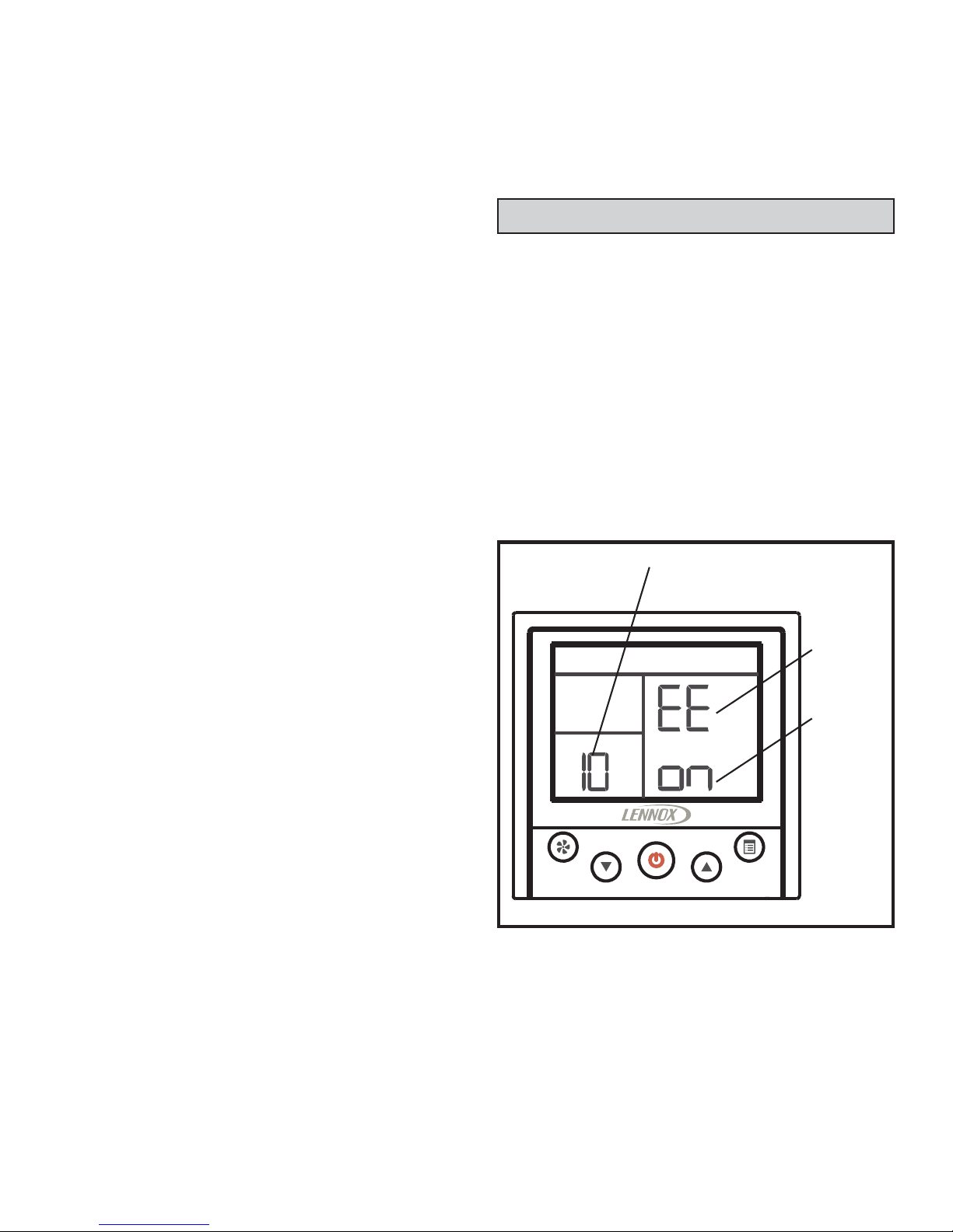
Controller Settings
• Press and hold the Fan speed button and
the Mode button for 5 seconds to access
the controller settings.
• Use Table 3 to setup the controller.
• When in Settings mode:
• Press the Fan speed button to accept
the current setting parameters and proceed to the next setting.
• Press the Up-arrow and Down-arrow
buttons to adjust parameters.
• Press the Power button to restart controller.
Centralized Controller Locks Controller
If a function of the indoor unit is locked by a
centralized controller (e.g. mode, temperature setpoint, swing, etc.), the V0STAT54P-2
controller will not be able to adjust that
locked function.
The function must be unlocked at the centralized controller before the local controller
can operate it.
MODEFAN SPEED
Figure 7. Controller Settings
Settings
Code
Settings Number
(see table 3)
Settings
Parameter
Page 12

12
Table 3. Controller Settings
Code Function Set-
tings
No.
Value Note
EE
Power off
– Memory
settings for
Auto Mode
NOTE – When
Auto mode is
being used,
setpoint, fan
speed, and
operation
mode (cooling
or heating) is
memorized
by the indoor
unit.
10 on (default)
When Auto mode is being
used, the controller will
memorize the user setting of
Auto mode before powering
off. When power is restored,
the controller mode will be set
to Auto mode.
11 off
When Auto mode is being
used, the controller will not
memorize the user setting of
Auto mode before powering
off. When power is restored,
the controller mode will be
set to the operation mode
of indoor unit (cooling or
heating).
CF
Temperature
unit
20 °C The controller will use °C
21 °F (default) The controller will use °F
Gr Not used 40 Not used Not used
Fr
Room
temperature
sensor location
50 0 Use indoor unit sensor
51 1 (default)
Use controller sensor
NOTE - Required setting if
multiple indoor units are connected to the controller.
Page 13
13
Code Function Set-
tings
No.
Value Note
t1
Room temperature sensor
calibration
60
Fahrenheit:-4°F/
-3°F/ -2°F/ -1°F/ 0°F
(Default)/ 1°F/ 2°F/
3°F/ 4°F
Celsius: -2°C/ -1°C/
0°C (Default)/ 1°C/
2°C
Adjust the calibration of the
room temperature senor.
Value selected will be added
to the temperature sensor
value.
Au
Auto mode enable/disable
70 on (default)
Auto mode enable (heat
recovery systems only)
71 off
Auto mode disable (heat
pump systems)
Th
Setpoint upper
limitation for
heating mode
80
Fahrenheit:
86°F~62°F (86°F
default)
Celsius: 30°C~17°C
(30°C default)
When the system is in heating mode, users can not set
the temperature higher than
the set value.
Tl
Setpoint lower
limitation for
cooling mode
90
Fahrenheit:
62°F~86°F (62°F
default)
Celsius: 17°C~30°C
(17°C default)
In cooling mode, users cannot set the temperature lower
than the set value.
FC
Set indoor unit
fan ON/OFF
when cooling
requirement is
satisfi ed.
A0 on (default)
Keeps the indoor fan on when
cooling setpoint is satisfi ed.
A1 off
Turns the indoor fan off when
cooling setpoint is satisfi ed.
Page 14

14
Code Function Set-
tings
No.
Value Note
FH
Set indoor unit
fan ON/OFF
when heating
requirement is
satisfi ed.
b0 on (default)
Keeps the indoor fan on when
heating setpoint is satisfi ed.
b1 --
Turns the indoor fan off when
heating setpoint is satisfi ed.
NOTE - FH code only. Simultaneously press the Fan Speed, Down-Arrow, Up-Arrow and
Mode buttons to toggle between “on” and “--”.
dr
HHE Relay
Kit - Enable
or Disable
Alternative
Heat (note:
see setting L0,
code d5 for
Alternate Heat
settings)
C0 on
Enable Alternative Heat using
the HHE Relay Kit.
C1 off (default)
Disable Alternative Heat using the HHE Relay Kit.
d1
HHE Relay Kit
- Auxiliary Heat
Settings
d3 3°F/2°C (default)
When using the HHE relay kit,
auxiliary heat will be activated
when room temperature is
3°F/2°C lower than setpoint in
heating mode.
d5 5°F/3°C
When using the HHE relay kit,
auxiliary heat will be activated
when room temperature is
5°F/3°C lower than setpoint in
heating mode.
Page 15
15
Code Function Set-
tings
No.
Value Note
d5
HHE Relay Kit Alternative Heat
Settings (note:
see setting CX,
code dr for to set
Alternative heat to
Enable/Disable).
When alternative
heat is enabled
and outdoor ambient temperature
is lower than
the setting, The
alternate heat
source is the only
heat source for
heating, the VRF
system will stop
supplying heat
until ambient
temperature is
higher than the
setting.
L0
0 7°F/-14°C
1 (default) 10°F/-12°C
2 15°F/-9°C
3 20°F/-7°C
4 25°F/-4°C
5 30°F/-1°C
6 35°F/-2°C
7 40°F/4°C
8 45°F/7°C
9 50°F/10°C
10 55°F/13°C
11 60°F/16°C
12 65°F/18°C
13 70°F/21°C
14 72°F/22°C
Page 16

16
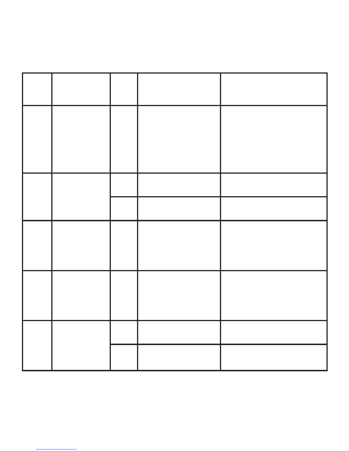
Indoor Unit Status Query
• Press and hold the Mode button for 5 seconds to access the indoor unit status query.
• Use the up-arrow and down-arrow buttons
to scroll through the indoor unit statuses
• Indoor unit operation status (Figure 8)
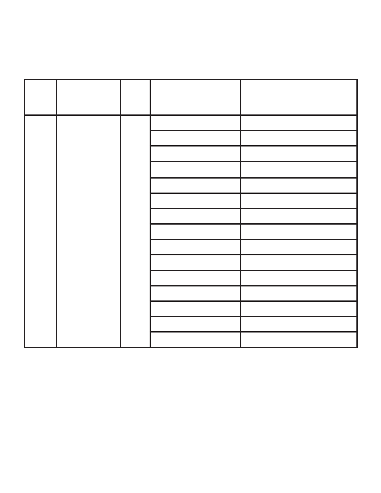
• Indoor unit evaporator coil temperature
(T2 and T2b) (Figure 9)
• Room temperature sensor location (wired
controller or indoor unit) (Figure 10)
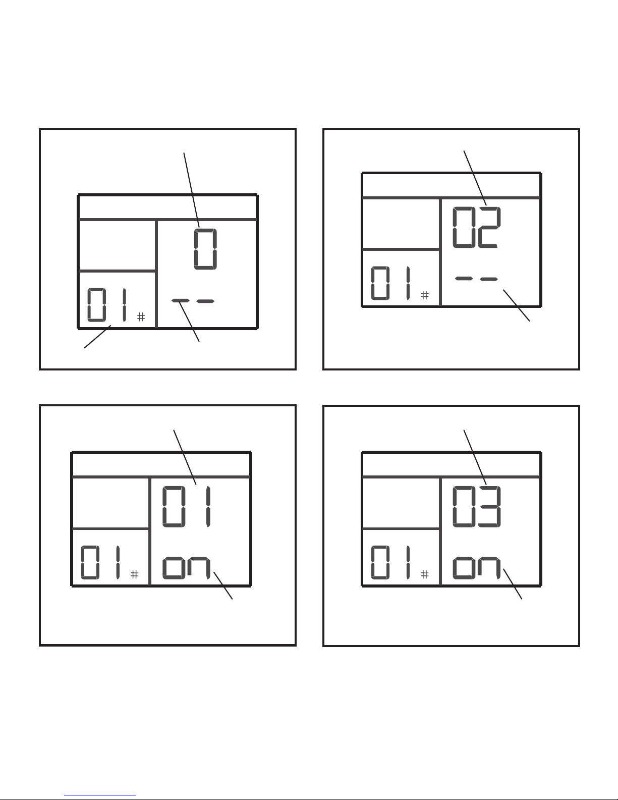
• On/Off status of dry contact one (Fan)
(Figure 11)
• On/Off status of dry contact two (CTON)
(Figure 12)
• On/Off status of dry contact three (HTON)
(Figure 13)
• On/Off status of dry contact four (AUXH)
(Figure 14)
FAN SPEED
COOL
SWING
Figure 8. Indoor Unit Operation Status
Setpoint
Operation Mode
Fan Speed
Indoor Unit Address
Figure 9. Indoor Unit Coil Temperature
T2b
T2
Indoor Unit Address
Louver
AutoSwing
Page 17
17
Figure 10. Room Temp Sensor Location
Room Temp Sensor Location
0 = Indoor Unit
1 = Controller
Indoor Unit Address
Figure 11. On/Off Status of HHE Relay - Fan
Figure 12. On/Off Status of HHE Relay - CTON
Figure 13. On/Off Status of HHE Relay - HTON
Not used
HHE Relay Four-Dry Contact - Fan
Dry Contact Status
on = Dry contact closed
-- = Dry contact open
HHE Relay Four-Dry Contact - CTON
Dry Contact Status
on = Dry contact closed
-- = Dry contact open
HHE Relay Four-Dry Contact - HTON
Dry Contact Status
on = Dry contact closed
-- = Dry contact open
Page 18
18
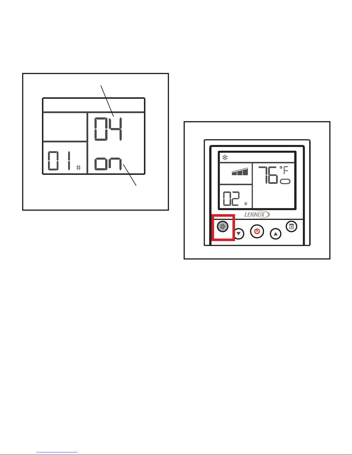
Figure 14. On/Off Status of HHE Relay Kit - AUXH
Figure 15. Switch to Next Indoor Unit
MODEFAN SPEED
FAN SPEED
COOL
Connected to Multiple Indoor Units
Press the Fan speed button to switch to additional indoor units. The controller will display
operation mode, fan speed, temperature setting, swing status and address of indoor unit.
HHE Relay Kit Four-Dry Contact - AUXH
Dry Contact Status
on = Dry contact closed
-- = Dry contact open
Page 19

19
Fault Code Query
Figure 16. Enter Fault Code Query
MODEFAN SPEED
Figure 17. View Past 10 Fault Codes
MODEFAN SPEED
Figure 18. Switch Between Fault Codes
MODEFAN SPEED
• Press and hold the Mode button for 5
seconds to access the indoor unit status
query.
• Press the Mode button to access the fault
code query. The last 10 fault codes are
stored.
• Press the Fan Speed button to scroll
through the fault codes.
• When multiple fault codes have occurred
at the same time, use the up-arrow and
down-arrow buttons to see each code.
Page 20

20
Error Codes
• The V0STAT54P-2 controller displays the
last 10 error codes. To view error codes,
see the instructions on the previous page.
• If the error code is for an indoor unit, the
unit address also displays.
Figure 19. Error Code Display
MODEFAN SPEED
Error Code
Indoor Unit Address
Table 4. Indoor Unit Error Codes
Error
Code
Description
F0
Communication error between
the indoor unit and the wired
controller (may affect other
indoor units in the system)
F1
Communication error between
the indoor unit and the controller
F2 Controller EEPROM error
E1
Communication error between
the indoor unit and the outdoor
unit
E2 T1 temperature sensor error
E3 T2A temperature sensor error
E4 T2B temperature sensor error
E5 Outdoor unit error
E6 Fan motor error
E7 Indoor unit EEPROM error
E8 Indoor unit DC motor error
EE Condensate pump error
 Loading...