

Page 1

1
©2015 Lennox Industries Inc.
Dallas, Texas, USA
OPERATION
INSTRUCTIONS
CONTROLS
507459-03
12/2015
This manual must be left with the
owner for future reference.
Frequent changes to operating
mode may cause system
malfunction. Allow at least one
minute between mode changes to
allow the system to stabilize.
IMPORTANT!
V0STAT52 Wireless
Indoor Unit Controller
Shipping and Packing List
Package 1 of 1 contains;
1 – Wireless Controller
2 – AAA batteries
Page 2

2
General
The V0STAT52 is a wireless local controller for VRF Heat Pump and Heat Recovery indoor units.
Requirements
• Point the wireless remote controller
directly at the indoor unit it controls.
36 ft. (11 m) maximum distance.
• Wireless remote control requires
direct line of sight to indoor unit.
• Do not get wireless remote controller
wet or submerge in liquid.
• Avoid placing wireless remote controller in direct sunlight or high temperature locations.
• Always use new AAA batteries.
• Remove the batteries if the wireless
remote controller will not be used for
a long period of time.
• Replace the batteries if the indoor
unit does not beep when settings are
changed using the controller.
• Do not attempt to operate any other
devices using this remote controller.
Specifi cations
Rated voltage
3.0 VDC
(2 AAA batteries)
Min voltage for sending signal to CPU 2.4 VDC
Effective transmitting distance 26-36 ft (8 - 11 m)
Operation conditions 23°F - 140°F
Page 3
3
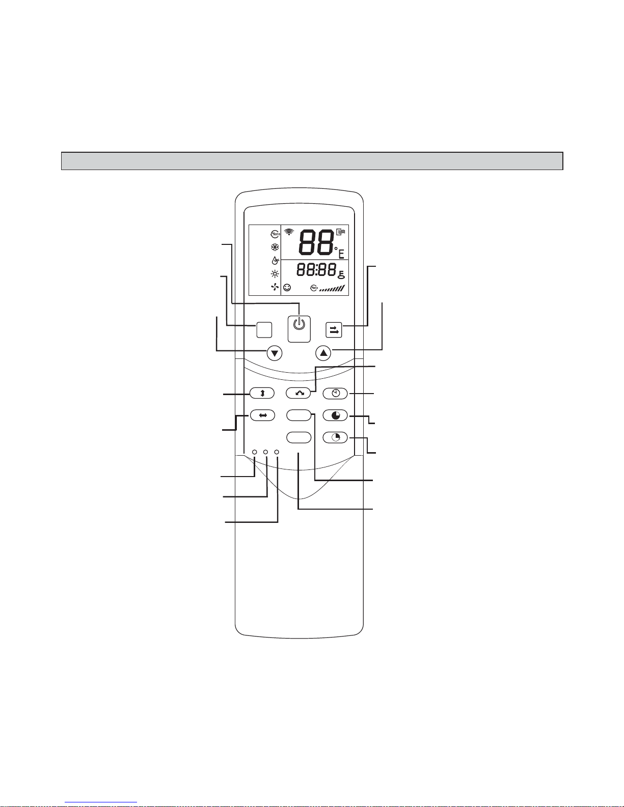
RESET
TIMER ON
TIME R OFF
CLOCK
SWIN G
AIR DIRECTION
OK
ECO
SWIN G
MODE
FAN
SPEED
M
AUTO
COOL
DRY
HEAT
FAN
TEMP
SET
CLOCK
SET
HOUR
FANS PEED
LOCK
C/H
Function Buttons
Mode
Down-arrow
Power
Vertical Swing
Horizontal Swing
Reset
Lock
Cool/Heat
Fan speed
Up-arrow
Air direction
Clock
Timer ON
Timer OFF
OK
Eco mode (not used)
Page 4

4
• Power button. Press to turn the in-
door unit on or off.
• Mode button. Press to scroll
through the operation modes:
Auto → Cool → Dry → Heat → Fan.
NOTE - Auto mode not available in all
systems.
• Down-arrow. Press to decrease the
temperature setpoint or scroll through
settings options.
• Vertical Swing button. Press once
to initiate louver up & down oscillation. Press again to stop louver oscillation. Louvers remain in place where
stopped. Not available in all indoor
unit models.
• Horizontal Swing button. Press
once to initiate louver left & right oscillation. Press again to stop louver
oscillation. Louvers remain in place
where stopped. Not available in all indoor unit models.
• Reset button. Using a blunt pointed
device (paper clip), press to cancel
current settings and reset remote controller to factory settings.
• Lock button. Using a blunt pointed
device (paper clip), press to lock or
unlock the current setting.
• Cool/heat button. Using a blunt
pointed device (paper clip), press to
shift between Cool only and Cool &
Heat modes. Default is Cool & Heat.
• Fan speed. Press to scroll through
the fan speeds: Low → Med → High
NOTE - Auto fan speed not available
for all systems.
• Up-arrow button. Press to increase
the temperature setpoint or to scroll
through settings options.
• Air direction button. Press to move
louvers up & down in 6 degree increments. Louvers remain in place where
stopped. Not available in all indoor
unit models.
• Clock button. Press to set clock time.
• Timer ON button. Press to set the
number of hours of delay before the
indoor unit to begins operation.
• Timer OFF button. Press to set the
number of hours of delay before the
indoor unit stops operation.
• OK button. Press to confi rm setting.
• Eco mode button. Not used.
Page 5

5
Display
AUTO
COOL
DRY
HEAT
FAN
TEMP
SET
CLOCK
SET
HOUR
FANSPEED
ON OF F
• Temp. Displays the setpoint tempera-
ture. Adjust with up & down-arrow buttons. No display when unit is in Fan
mode.
• Transmitting display. Icon blinks
once when a signal is sent from the
wireless remote controller.
• Running mode. Displays the
selected mode.
• Economy operation. Not used.
Temp
Transmitting display
Operation mode
Economy operation
On/Off
Lock
Time
Timer ON/OFF
Fan speed
• On/Off. Icon displays to indicate the
last command sent by the Power
button.
• Time. Displays the current time.
• Lock. Icon displays when Lock but-
ton is pressed.
• Timer ON/OFF. Icon lights up to
indicate whether the timer is ON or
OFF.
• Fan speed. Displays the current fan
speed.
Page 6

6
Operation Instructions
Batteries
1. Grasp the controller cover by its sides
and slide the cover down to remove.
2. Place batteries into battery compartment.
3. Replace cover onto controller.
Auto mode
System will automatically switch between heating and cooling depending on
the temperature sensed at the controller.
NOTE - Auto mode not available in all
systems.
Cool/Heat/Fan mode
1. Press the Mode button to select Cool,
Heat, or Fan.
2. Adjust the temperature setpoint
using up and down-arrow buttons for Cool or Heat modes.
NOTE
– Temperature setpoint cannot
be adjusted when in Fan mode.
3. Press the Fan speed button to select
Auto, Low, Med, or High fan speed.
NOTE - Auto fan speed not available
for all systems.
4. Press the Power button to turn on indoor unit, the LED on the indoor unit
displays.
Dry mode
1. Press the Power button, an LED light
on the indoor unit displays.
2. Press the Mode button to select Dry.
3. Adjust the temperature setpoint using
up and down-arrow buttons.
NOTE – Fan speed is unavailable when
in Dry mode.
Timer operation
Timer ON and Timer Off are used to turn
on and turn off the indoor unit at selected
intervals.
Timer ON operation
1. Press the Timer ON button. TIMER
displays. HOUR and ON lights up.
2. Press the Timer ON button again and
use the up-arrow and down-arrow buttons to set the number of hours of delay before the indoor unit begins operation. The time will increase in half
hour increments until 10 hours, then
the increment becomes 1 hour.
Timer OFF operation
1. Press the Timer OFF button. TIMER
displays. HOUR and OFF lights up.
Page 7

7
2. Press the Timer OFF button again
and use the up-arrow and down-arrow
buttons to set the number of hours of
delay before the indoor unit stops operation. The time will increase in half
hour increments until 10 hours, then
the increment becomes 1 hour.
Modify Timer ON/OFF settings
1. Press either the Timer ON button or
the Timer OFF button to modify that
setting.
2. Use the up-arrow and down-arrow
buttons to change the timed operation
intervals.
3. Set the timer to 0.0 to turn off timed
operation.
Set Clock Time
1. Press and hold the Clock button for
5 seconds, the Hour indicator will
display.
2. Press the up-arrow and down-arrow buttons to select hour.
3. Press the Clock button again, the
Minute indicator displays.
4. Press the up-arrow and down-arrow buttons to select minutes.
5. Press the OK button to confi rm
time.
Page 8

8
Troubleshooting
Digital
Tube
Display
Content
F0 Wired remote controller
and indoor unit communication failure
E1 Communication error be-
tween indoor and outdoor
units
E2 Indoor ambient tempera-
ture sensor (T1) error
E3 Middle evaporator tem-
perature sensor (T2) error
E4 Evaporator outlet tempera-
ture sensor (T2B) error
EE Water level alarm error
E7 Indoor Unit EEPROM error
E0 Mode confl ict error
Ed Outdoor units error
FE IDU doesn’t have address
when it is fi rst turned on
Temperature Sensing
Indoor Unit
Default sensor. All indoor units have
a temperature sensor that senses the
zone temperature and controls operation of the indoor unit within the limits of
the system.
Remote Sensor
Field installed accessory. Used to relocate temperature sensor from indoor
unit to remote location.
 Loading...