

Page 1

©2019 Lennox Industries Inc. Dallas, Texas, USA
VRF
!
WARNING
Improper installation, adjustment,
alteration, service or maintenance can
cause property damage, personal injury
or loss of life.
Installation and service must be
performed by a licensed professional
HVAC installer (or equivalent) or service
agency.
CAUTION
To ensure proper system performance and
reliability, Lennox does not recommend
operation of VRF systems during any phase
of construction. Construction debris, low
temperatures, harmful vapors, and operation
of the unit with misplaced lters can damage
the units. Failure to follow these guidelines
will result in the warranty being voided.
IMPORTANT
Frequent changes to operating mode
may cause system malfunction. Allow at
least one minute between mode changes
to allow the system to stabilize.
This manual must be left with the
owner for future reference.
INSTALLATION/
OPERATION
INSTRUCTIONS
V0STAT51P-3 Touch Screen
Programmable Local Controller
CONTROLS
507900-01
03/2019
General
The V0STAT51P-3 is a wired touch screen
programmable local controller for VRF Heat
Recovery and Heat Pump indoor units with
convenient timed schedules for daily operation.
These instructions are intended as a general
guide and do not supersede local codes in any
way. Consult authorities having jurisdiction before installation.
Requirements
Be sure that power supply has been turned
o before beginning installation. This controller should be used only as described in this
manual.
Shipping and Packing List
Package 1 of 1 contains;
1 – Wired Controller
1 – CR2032 Lithium battery
2 – Phillips screws
2 – Plastic spacers
2 – 1/8” polymer toggle anchors
1 – Installation and operation manual
Tools Needed
#2 Phillips screwdriver
Slotted precision screwdriver
Level
1/8” wall anchor tools
Controller Placement
Avoid installing local controller in high load
or heat loss areas such as exterior walls or
walls that are against unconditioned spaces,
near entry doors and windows, or where direct sunlight may be present.
1
Page 2

Contents
General ........................................................................................................................................1
Requirements ..............................................................................................................................1
Shipping and Packing List ..........................................................................................................1
Tools Needed...............................................................................................................................1
Controller Placement ..................................................................................................................1
Installation ...................................................................................................................................4
Connecting to One Indoor Unit ............................................................................................5
Connecting to Multiple Indoor Units ....................................................................................6
Mounting the Controller .......................................................................................................7
Home Screen Display ................................................................................................................10
Operation ...................................................................................................................................14
ON/OFF .............................................................................................................................14
Error Code Display ............................................................................................................15
Mode Settings............................................................................................................................16
Cooling Mode Operation ...................................................................................................16
Heating Mode Operation ..................................................................................................17
Auto Mode Operation ........................................................................................................18
Dry Mode Operation ..........................................................................................................20
Fan-Only Operation ...........................................................................................................21
Temperature Setpoint .......................................................................................................22
Space Temperature and Space Humidity Display ............................................................23
Temperature Unit Switching (ºF/ºC) ...................................................................................24
Fan Speed .........................................................................................................................25
Swing .................................................................................................................................26
Weekly Schedule Settings Quick Access ..........................................................................27
Override Settings ...............................................................................................................28
Schedule Management..............................................................................................................29
Setup Schedule Templates ................................................................................................31
Paste a Schedule ..............................................................................................................32
Copy and Paste a Schedule Template ..............................................................................32
Copy a Schedule ..............................................................................................................32
Rename a Schedule Template ..........................................................................................34
Delete a Schedule Template .............................................................................................35
Add a Daily Schedule Action .............................................................................................36
Delete a Daily Schedule Action .........................................................................................37
Rename a Daily Schedule Action ......................................................................................37
Edit a Daily Schedule Action .............................................................................................38
Setup a Weekly Schedule .................................................................................................39
Tap the Add button. ...........................................................................................................40
Rename a Weekly Schedule .............................................................................................41
Delete a Weekly Schedule ................................................................................................42
Modify a Weekly Schedule ................................................................................................43
Select the Weekly Schedule to Use ..................................................................................44
Setup Holiday and Special Day Schedules .......................................................................45
Add a Holiday and Special Day Schedule .........................................................................46
Rename a Holiday and Special Day Schedules ................................................................47
Modify a Holiday and Special Day Schedules ...................................................................48
Delete a Holiday and Special Day Schedules ...................................................................49
Override Scheduled Settings .............................................................................................50
General Settings Conguration .................................................................................................52
Time Format Settings ........................................................................................................53
Time Settings .....................................................................................................................53
Theme Settings .................................................................................................................54
2
Page 3

Brightness Settings ...........................................................................................................54
Controller Touch Tone (Sound) Settings ............................................................................ 55
Standby Interface (Screen Saver) Settings .......................................................................56
Standby (Screen Saver) Duration Settings .......................................................................57
Swing Angle Settings ................................................................................................................. 58
Daylight Savings Time Settings .................................................................................................58
Room Temperature and Humidity Display Settings ...................................................................61
Contractor Information Input ......................................................................................................62
Service Menu.............................................................................................................................63
Access Service Menu ........................................................................................................63
Change Password .............................................................................................................64
Master / Sub Wired Controller Settings .....................................................................................65
Master / Sub Wired Controller Operation ..................................................................................66
Indoor Unit Address Settings .....................................................................................................68
Indoor Unit Display Board & Buzzer (Sound) Settings ..............................................................69
Room Temperature Sensor Settings .........................................................................................70
Auto Mode Settings ...................................................................................................................72
Draft (Cold Blow) Prevention Settings .......................................................................................74
Stand-by Fan Speed Settings....................................................................................................75
Indoor Unit Static Pressure Settings..........................................................................................76
Occupancy Sensor Function Settings .......................................................................................77
Dry Mode Settings .....................................................................................................................78
Auxiliary / Alternate Heat Settings .............................................................................................79
Setpoint Limit Settings ...............................................................................................................81
Locking Function Settings .........................................................................................................82
Advanced Information................................................................................................................83
Device Operation Information Query .................................................................................84
Device Operation Error History Query ...............................................................................86
HHE Dry Contact Relay Interface Status Query ................................................................90
Controller Information ........................................................................................................91
Firmware and Setting Information .............................................................................................92
Software Version ...............................................................................................................93
Controller Software Update ...............................................................................................94
Indoor Unit Software Update .............................................................................................96
Setting Parameters Backup ...............................................................................................99
Setting Parameters Import ..............................................................................................100
Reset Settings .................................................................................................................101
Help .........................................................................................................................................102
Get On-screen Help ........................................................................................................102
3
Page 4

Installation
!
WARNING
Be sure that power supply has been
turned o before beginning installation.
Do not operate controller with wet hands.
!
CAUTION
Do not install controller in areas where
harmful gases containing sulfur or
other damaging agents may exist or the
controller may be damaged.
Clean controller using a clean, damp
cloth. Do not spray cleanser on or around
controller.
IMPORTANT
Electrostatic discharge can aect electronic
components. Take precautions to neutralize
electrostatic charge by touching your hand
and tools to metal prior to handling the control.
IMPORTANT
Read all of the information in this manual
before using this controller. All wiring must
conform to local and national building and
electrical codes and ordinances. This is a
12 VDC controller. Do not install on voltages
higher than 12 VDC.
• This manual provides the installation
instructions for this controller. Refer to the
included wiring diagrams to connect the
controller to the indoor unit.
• The controller uses low voltage. Keep a
minimum distance of 12” (305 mm) between
low voltage control wire and high voltage
power wires.
Power wiring between controller and rst
indoor unit:
• Minimum 18 AWG stranded, shielded cable
up to 164 feet (50 m).
• Ensure there are no gaps between the controller back cover and the mounting surface.
• Fill any holes in the wall behind the control-
ler to avoid false readings from inltration.
• Ground the shielded control wiring.
• Do not use a megger to test insulation.
Communication wiring between indoor
units:
• Minimum 18 AWG stranded, shielded cable.
4
Page 5

Connecting to One Indoor Unit
Connect the controller to one indoor unit main control board using 4-conductor shielded 18 GA
cable. Connect to terminals 12V,COM,HA,HB. See Figure 1.
HB
HB
HA
NOTE - 1. Connect up to 16 indoor units
2. Ground cable shielding at indoor unit
3. All wiring is polarity sensitive
Figure 1. Connect Controller to Single Indoor Unit Wiring Connections
COM
12V
HA
COM
12V
5
Page 6

Connecting to Multiple Indoor Units
Connect the controller to multiple indoor units, up to 16. Use 4-conductor shielded cable to connect
to the rst indoor unit, then daisy chain control wiring to each indoor unit using the HA/HB terminals
in the electrical control box of the indoor unit. Do not daisy chain 12V power cable. See Figure 2.
NOTE – All of the indoor units connected to the controller must be on the same refrigerant circuit,
connected to the same outdoor unit.
HB
HA
HB
HA
COM
COM
12V
12V
NOTES - 1. Connect “+12V” on the controller to terminal “+12V” on the first indoor
unit only. 12V connection provides power to controller; connection to
multiple indoor units will damage controller and indoor unit boards.
2. Ground cable shielding at each indoor unit.
4. Use stranded, shielded, 18 GA cable.
5. Connect up to 16 indoor units.
HB
HA
COM
12V
Figure 2. Connect Controller to Multiple Indoor Units Wiring Connections
CAUTION
Connect “12V” on the controller to
terminal “12V” on the rst indoor unit
only. 12V connection provides power to
controller; connection to multiple indoor
units will damage controller and indoor
unit boards.
HB
HA
COM
12V
6
Page 7

Mounting the Controller
1. Remove the back cover from the controller. See Figure 3.
Figure 3. Remove Back Cover from Controller
2. Attach the back cover to the wall using screws. See Figure 4.
Figure 4. Attach Back Cover to Wall
7
Page 8

3. Connect the controller to one indoor unit main control board using 4-conductor shielded 18 GA
cable. Connect to terminals 12V,COM,HA,HB on the back of the controller.
HA HB
12V COM
HB
HA
COM
P12V Q
Figure 5. Connect Cabling
4. Insert the controller into the bottom snap joints of the back cover at an angle. See Figure 6.
Figure 6. Insert Controller into Back Cover
8
Page 9

5. Push the controller back toward the wall until it “snaps” into place. See Figure 7.
Figure 7. Snap Controller Into Place
9
Page 10

Home Screen Display
3
4
7
5
8
2
10
6
9
1
Figure 8. Home Screen Display 1
15
11
14
13
12
Figure 9. Home Screen Display 2
10
16
17
18
Page 11

Table 1. Home Screen Display
Number Display Item Description
1 ON/OFF button Tap to turn the indoor unit on or o.
2 Settings button Tap to access the menu screen.
3 Time Display Displays the current system time.
Select Auto mode when the indoor unit is ON, and then
4 Auto Mode Settings
the indoor unit will run in Auto mode (the icon illuminates
after selection).
Select Cooling mode when the indoor unit is ON, and
5 Cooling Mode Settings
then the indoor unit will run in Cooling mode (the icon
illuminates after selection).
Select Heating mode when the indoor unit is ON, and
6 Heating Mode Settings
then the indoor unit will run in Heating mode (the icon
illuminates after selection).
Select Dry mode when the indoor unit is ON, and then the
7 Dry Mode Settings
indoor unit will run in Dry mode (the icon illuminates after
selection).
Select Fan mode when the indoor unit is ON, and then the
8 Fan Mode Settings
indoor unit will run in Fan mode (the icon illuminates after
selection).
9
Temperature Unit Settings
Switch the temperature unit: display in
Fahrenheit/Celsius temperature.
10 Operation Mode Displays the mode of operation of the indoor unit.
11
12
Fan Speed Control
Button
Indoor Temperature
and Humidity Display
Select fan speed, and tap “Auto”, “High”, “Med”, or “Low”
to conrm the selection.
Display the temperature and humidity of the room in
which the indoor unit is located.
13 Setpoint Displays the setpoint.
14
15
16
17
18
Setpoint Adjustment
Slider
Vertical Swing Angle
Display
Horizontal Swing Position Display
Weekly Schedule
Display
Override Status
Display
Adjust the setpoint by pressing and sliding.
Displays the vertical swing angle of the indoor unit; tap to
access the vertical swing angle settings.
Display the horizontal swing angle of the indoor unit; tap
to enter the horizontal swing angle settings.
Display the setting status of the weekly schedule status,
and tap to access the weekly.
Display the Override status and tap here to set the
Override settings.
11
Page 12

Table 2. Special Status Symbol Displays
No. Icon Name Description
1 Fan
2 Cool
3 Heat
4 Dry
5 Cooling operation in Auto mode
6 Heating operation in Auto mode
7 Centralized controller lock
8 Group control
9 Occupancy sensor
Displays when the indoor unit is in Fan
mode.
Displays when the indoor unit is in
Cooling mode.
Displays when the indoor unit is in
Heating mode.
Displays when the indoor unit is in Dry
mode.
Displays when the indoor unit is in Auto
mode providing cooling operation.
Displays when the indoor unit is in Auto
mode providing heating operation.
Displays when some functionality is
locked by a centralized controller.
Displays when more than one indoor
unit is connected to the controller.
Displays when an occupancy sensor
is active.
10 Help Tap to see the Help screens.
Displays when the indoor unit is in
11 Mode conict prompt
mode conict with the outdoor unit
(heat pump systems)
12 Auto Dry function Displays when auto dry function is ON.
13 Master controller Displays if the controller is a master.
14 Master controller Displays if the controller is a sub.
15 Outside air ducted indoor unit
16 ON/OFF lock
Displays if the connected indoor unit is
providing outside air.
Displays when some functionality is
locked by settings on this controller.
17 Mode lock Displays when Mode is locked.
12
Page 13

No. Icon Name Description
18 Setpoint lock Displays when Setpoint is locked.
19 Schedule lock Displays when Schedule is locked.
20 Defrosting or oil return
20 Cold air prevention
Displays when the outdoor unit is in
defrost or oil return operation.
Displays during period of time before
the coil warms to the determined cold
air prevention temperature. The fan
will not run during this time period.
13
Page 14

Operation
NOTE - Indoor units connected to a local controller may also be controlled by a centralized controller. Indoor units respond to the last command sent. It is recommended that indoor units be controlled from a single source of control, either local controller or centralized controller but not both,
to avoid conicts in commands.
ON/OFF
Tap the On/O button to turn the indoor unit on or o.
Figure 10. ON/OFF Operation
14
Page 15

Error Code Display
When the connected indoor units or outdoor unit has an error, the original set temperature interface will display the error code.
Tap the error display area and to open the error code description interface.
Figure 11. Error Code Display
15
Page 16

Mode Settings
Cooling Mode Operation
When the indoor unit is powered on, tap COOLING in the operating mode selection interface.
The selected icon will illuminate when the indoor unit runs in Cooling mode. The Cooling icon is
displayed in the upper right corner of the home page.
To adjust the setpoint, tap the setpoint slider and drag the slider to the new setpoint temperature.
The default setpoint range is 62°F to 86°F (17°C to 30°C).
Figure 12. Cooling Mode Operation
16
Page 17

Heating Mode Operation
When the indoor unit is powered on, tap HEATING in the operating mode selection interface. The
selected icon will illuminate when the indoor unit runs in Heating mode. The Heating icon is displayed in the upper right corner of the home page.
To adjust the setpoint, tap the setpoint slider and drag the slider to the new setpoint temperature.
The default setpoint range is 62°F to 86°F (17°C to 30°C).
Figure 13. Heating Mode Operation
17
Page 18

Auto Mode Operation
When the indoor unit is powered on, tap AUTO in the operating mode selection interface. The selected icon will illuminate when the indoor unit runs in Auto mode. The Auto icon or the Cooling icon
is displayed in the upper right corner of the home page.
NOTE - During Auto mode, both operation mode (cooling or heating) setpoints display on the Home
screen. The current operation mode setpoint displays larger than the non-current operation
mode.
In Auto mode the Cooling setpoint range is 68°F to 86°F (20°C to 30°C), the Heating setpoint range
is 62°F to 81°F (17°C to 27°C).
To adjust the setpoint of either cooling or heating while in Auto mode, tap the appropriate setpoint,
either cooling or heating. That setpoint will display as the larger number. Drag the temperature
slider to the new setpoint temperature. If the setpoint you adjusted is not the current operation
mode, after 10 seconds, the current operation mode setpoint will display as the larger number.
NOTE - The setpoint deadband between cooling and heating setpoints is setup in the Settings
menu.
Figure 14. Auto Mode Operation
18
Page 19

Figure 15. Auto Mode Setpoints
19
Page 20

Dry Mode Operation
When the indoor unit is powered on, tap DRY in the operating mode selection interface. The selected icon will illuminate when the indoor unit runs in Dry mode. The Dry icon is displayed in the
upper right corner of the home page.
Fan speed cannot be adjusted during Dry mode.
Figure 16. Dry Mode Operation
20
Page 21

Fan-Only Operation
When the indoor unit is powered on, tap FAN in the operating mode selection interface. The selected icon will illuminate when the indoor unit runs in Fan mode. The Fan icon is displayed in the
upper right corner of the home page.
The indoor unit fan operates without heating or cooling.
Figure 17. Fan-Only Mode Operation
21
Page 22

Temperature Setpoint
To adjust the setpoint, tap the setpoint slider and drag the slider to the new setpoint temperature.
The default setpoint range is 62°F to 86°F (17°C to 30°C). The setpoint range can be adjusted using the Setpoint Limit screen in the Service menu.
Figure 18. Temperature Setpoint
22
Page 23

Space Temperature and Space Humidity Display
On the main screen of the controller, you can view the current setpoint, space temperature and
space humidity.
When the master wired controller chooses the Follow function, the Space Temp will display the
temperature and corrected value detected by the temperature sensor of the master wired controller
itself.
When the master and Sub wired controllers do not choose the Follow function, their Space Temp
will display the temperature detected by their own temperature sensors (without a corrected value).
The temperature sampling range is -16°F to 156°F (-9°C to 70°C). The humidity sampling range
is 0% to 100%.
Figure 19. Setpoint, Space Temperature & Space Humidity Display
23
Page 24

Temperature Unit Switching (ºF/ºC)
Tap TEMPERATURE UNIT SETTING at the lower right corner to switch the temperature display
unit between Fahrenheit and Celsius.
Figure 20. Fahrenheit or Celsius Temperature Display
24
Page 25

Fan Speed
Tap Auto, High, Med, or Low to change the fan speed. The corresponding icon illuminates after
selection.
Figure 21. Fan Speed Operation
25
Page 26

Swing
Tap the Vertical Swing Angle Settings icon and the Horizontal Swing Angle Settings icon to enter
the swing angle settings interface.
Figure 22. Swing Settings
26
Page 27

Weekly Schedule Settings Quick Access
Tap the Weekly Schedule Settings icon to enter the weekly schedule settings interface.
Figure 23. Quick Access to Weekly Schedule Settings
27
Page 28

Override Settings
Tap the Override icon and the Override delay time selection box displays.
Figure 24. Override Settings
28
Page 29

Schedule Management
NOTE – If schedules are used and a centralized controller is installed on the system, controller
functions should not be locked from the centralized controller.
Tap the Schedule button to access the schedule management settings interface.
Set by week, and run dierent set statuses at dierent times of the day.
Before setting Schedule Templates, Schedule Setup, and Holiday and Special Day Schedule, you
must rst complete the date and time settings.
Figure 25. Tap Schedule Button to access Schedule Settings
29
Page 30

If the system time is detected to be earlier than 01:00 AM Dec 30, 2017 (the factory default time is
2017-12-30), the setting date and time box will display.
Tap “YES” to open to the date and time settings screen, or tap “NO” to return to the previous
page.
Figure 26. Set System Date & time
30
Page 31

Setup Schedule Templates
Create a scheduled day’s events. Tap the Schedule Templates button to access the daily schedule template settings interface.
Figure 27. Tap Schedule Templates Button
Tap the Add button to add a daily schedule template. Up to 10 templates.
Figure 28. Add Daily Template
31
Page 32
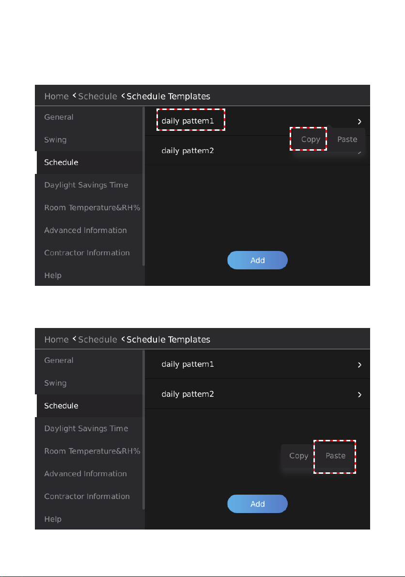
Copy and Paste a Schedule Template
Use the Copy and Paste buttons to copy a template and use it to create a new daily template.
Copy a Schedule
Press and hold the schedule template you want to copy. The Copy and Paste buttons will display.
Tap the Copy button.
Figure 24. Copy or Paste a Daily Schedule Template
Figure 29. Copy a Schedule Template
Paste a Schedule
After copying a scheduled template, tap the Paste button.
Figure 30. Paste to Create a New Schedule Template
32
Page 33
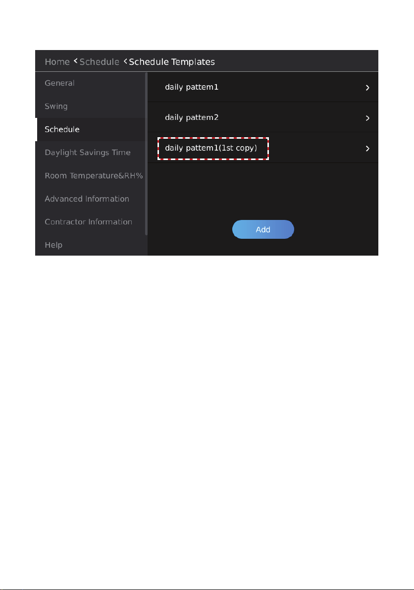
The new schedule template will display. Rename the template as needed.
Figure 31. New Schedule Template
33
Page 34
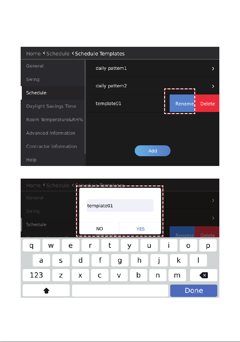
Rename a Schedule Template
Slide the daily schedule template to be deleted from the right to left, and “Rename” and “Delete”
boxes will display. Tap Rename and enter the new name in the Edit box. Tap Yes to conrm. Tap
Cancel to return to the previous screen.
Figure 32. Rename a Schedule Template
Figure 33. Enter Schedule Template Name
34
Page 35
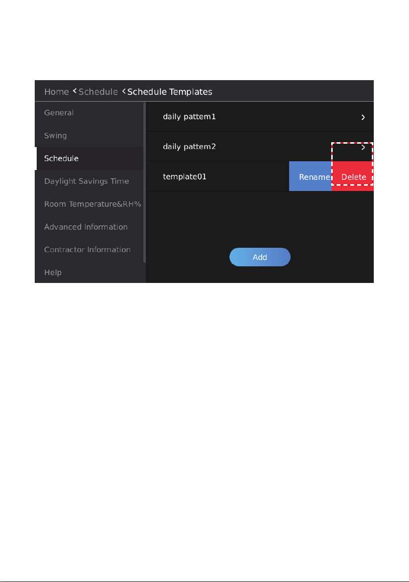
Delete a Schedule Template
Slide the daily schedule template to be deleted from the right to left, and “Rename” and “Delete”
boxes will display. Tap Delete and Tap Yes when prompted. Tap Cancel to return to the previous
screen.
Figure 34. Delete a Schedule Template
35
Page 36
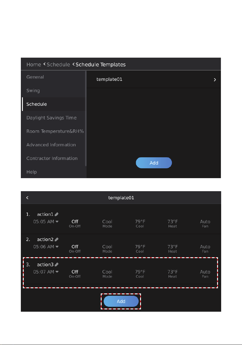
Add a Daily Schedule Action
Tap the template to add the action to. Maximum of 8 actions per daily schedule template.
The Action setup screen will display. Select the Action’s Start Time, ON/OFF status, Operation
Mode, Cooling Setpoint, Heating Setpoint and Fan speed. Each action will end at the Start time of
the next action.
Figure 35. Add a Daily Schedule Action
Figure 36. Setup Daily Schedule Action
36
Page 37
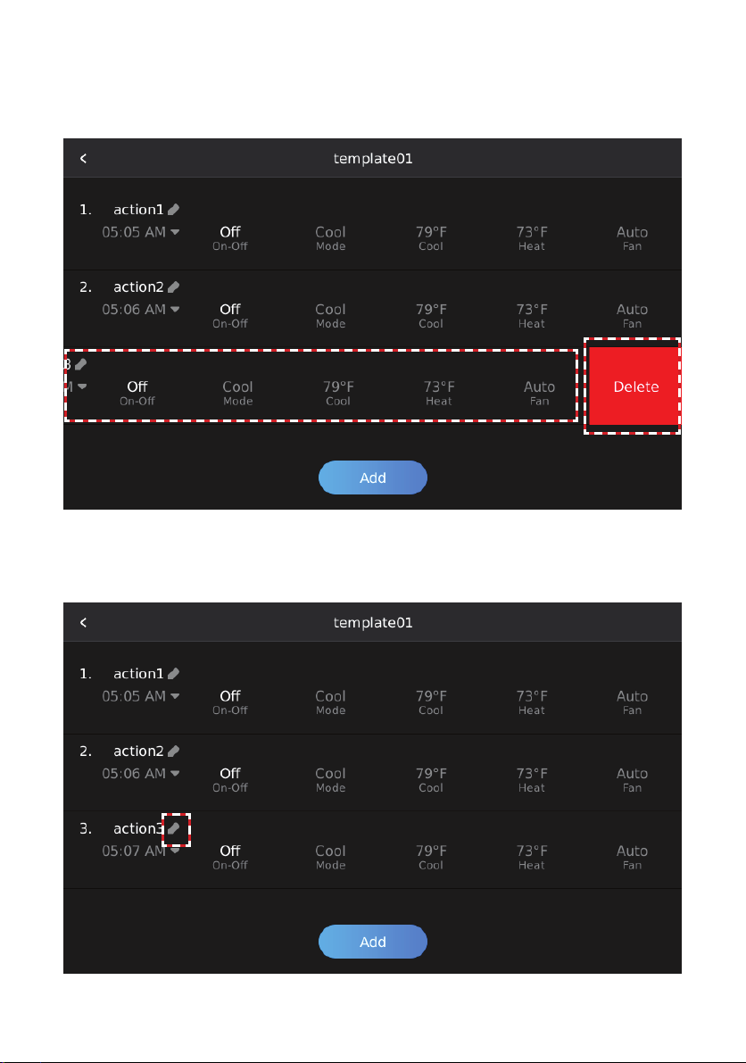
Delete a Daily Schedule Action
Slide the daily schedule action that needs to be deleted from right to left, and the Delete box will
display.
Tap Delete to delete the daily schedule action.
Figure 37. Delete Daily Schedule Action
Rename a Daily Schedule Action
Tap the Edit button on the right of the action to rename the event.
Figure 38. Rename a Daily Schedule Action
37
Page 38
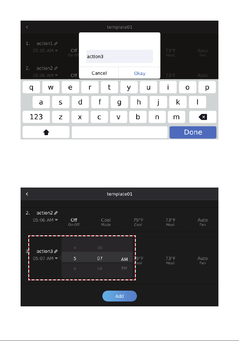
Figure 39. Rename a Daily Schedule Action Edit Box
Edit a Daily Schedule Action
Tap the daily schedule action content (e.g., time) that needs to be modied, and enter the daily
schedule action content editing mode.
Slide up/down to increase/decrease the value and modify the daily schedule action content.
The highlighted value in the middle is the currently set parameter.
Figure 40. Modify a Daily Schedule Action
38
Page 39
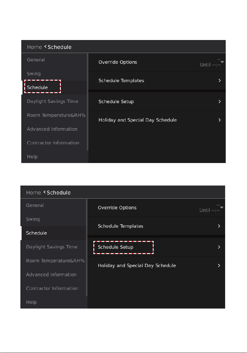
Setup a Weekly Schedule
Create a Weekly Schedule. Tap the Schedule button to access the schedule management settings
interface.
Figure 41. Tap Schedule Button to Access Schedule Settings
Tap the Schedule Setup button. The Schedule Setup screen will display.
Figure 42. Tap Schedule Setup Button
39
Page 40
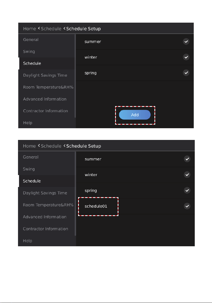
Tap the Add button.
Figure43. Add a New Weekly Schedule
Figure 44. New Weekly Schedule
40
Page 41
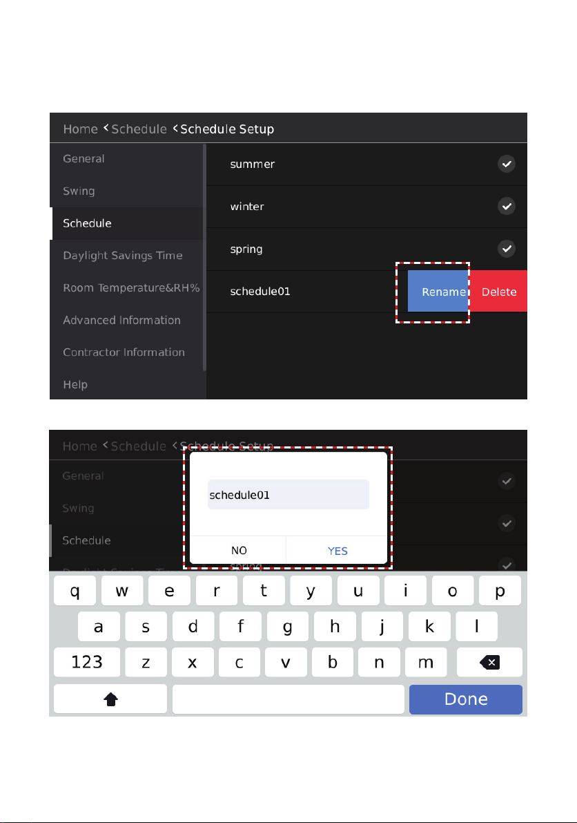
Rename a Weekly Schedule
Slide the weekly schedule to be deleted from the right to left, and “Rename” and “Delete” boxes
will display. Tap Rename and enter the new name in the Edit box. Tap Yes to conrm. Tap Cancel
to return to the previous screen.
Figure 45. Rename a Weekly Schedule
Figure 46. Enter Weekly Schedule Name
41
Page 42

Delete a Weekly Schedule
Slide the weekly schedule to be deleted from the right to left, and “Rename” and “Delete” boxes
will display. Tap Delete and Tap Yes when prompted. Tap Cancel to return to the previous screen.
Figure 47. Delete a Schedule Template
Figure 47. Conrm Deletion
42
Page 43

Modify a Weekly Schedule
Enter the weekly schedule template content editing interface.
Tap the drop-down button on the right of “Everyday” and select the weekly schedule combination
mode.
Figure 49. Modify a Weekly Schedule
Table 3. Schedule Options
Schedule Description
Everyday
Set the schedule independently for each
day of the week.
Set the schedule uniformly for Monday
5+1+1
through Friday and independently for Saturday and Sunday.
Set the schedule uniformly for Monday
5+2
through Friday and uniformly for Saturday
and Sunday.
7
Set the schedule uniformly for each day of
the week.
43
Page 44

Tap the “daily pattern2” drop-down button to import the desired daily schedule template.
Figure 50. Select Daily Schedule Templates to Include in the Weekly Schedule
Select the Weekly Schedule to Use
Tap the button on the right of the weekly schedule template you want to select to complete the
weekly schedule selection. The selected icon is highlighted after selection.
44
Page 45

Setup Holiday and Special Day Schedules
Create a special schedule for holidays. Tap the Schedule button to access the schedule management settings interface.
Figure 51. Tap Schedule Button to Access Schedule Settings
Tap the Holiday and Special Day Schedule button. The Holiday and Special Day Schedule screen
will display.
Figure 52. Tap Schedule Setup Button
45
Page 46

Figure 53. Holiday & Special Day Schedule Screen
Add a Holiday and Special Day Schedule
Tap the Add button to create a new holiday schedule. The new schedule displays at the end of the
list.
Figure 54. New Holiday & Special Day Schedule
46
Page 47

Rename a Holiday and Special Day Schedules
Tap the name of the holiday schedule that you want to modify, enter the rename edit interface, and
type the name of the holiday.
Tap YES to nish naming and modifying the holiday schedule, or tap NO to return to the previous
page.
Figure 55. New Holiday & Special Day Schedule
Figure 56. Rename Holiday & Special Day Schedule
47
Page 48
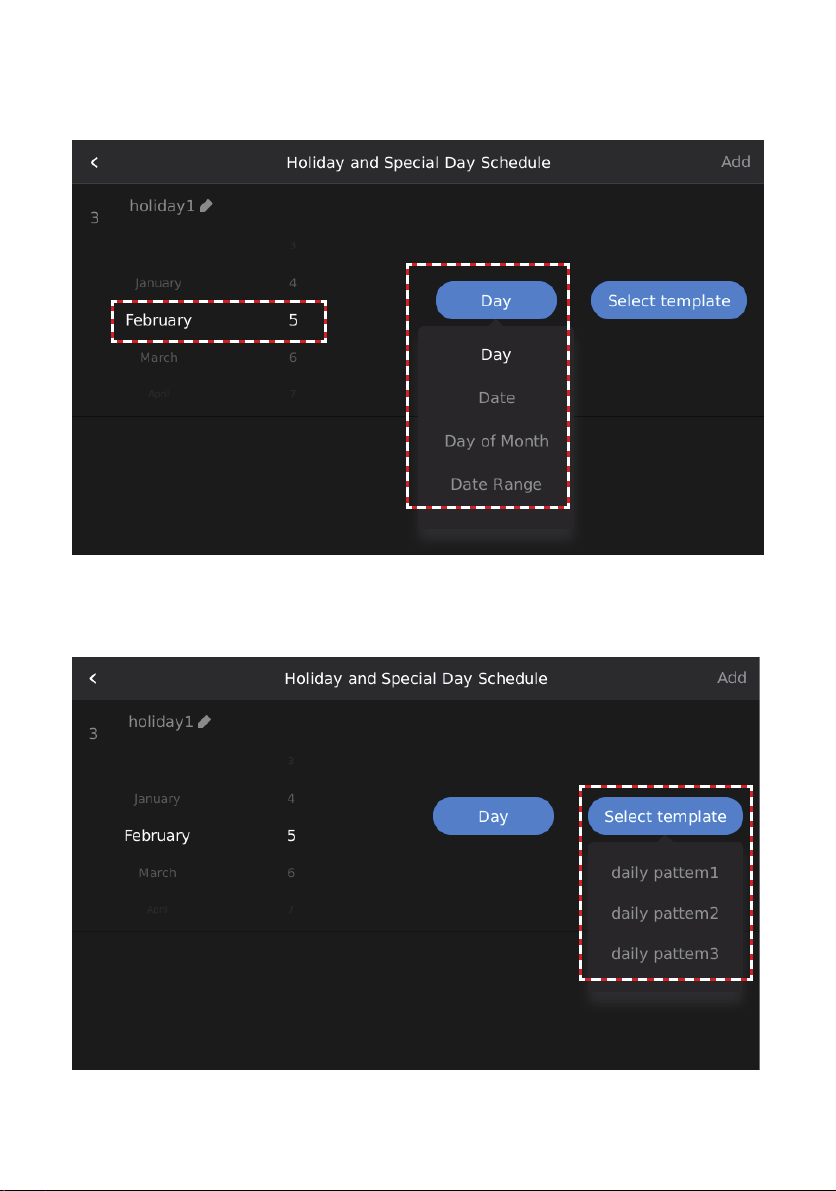
Modify a Holiday and Special Day Schedules
Tap the Day button of the holiday schedule that needs to be edited, select the type of holiday schedule date setting and set the date.
Figure 57 Select the Type of Holiday & Special Day Schedule
Tap the Select template button for the holiday schedule to be edited and select the daily schedule
template for the holiday.
Figure 58. Select the Daily Schedule Template for the Holiday Schedule
48
Page 49
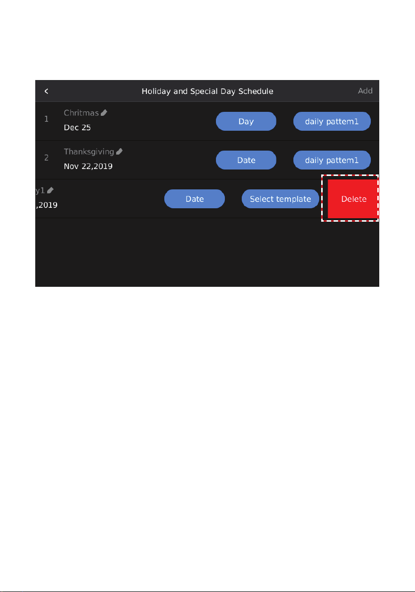
Delete a Holiday and Special Day Schedules
Slide the holiday schedule (e.g., holiday1) that needs to be deleted from right to left, and then a
Delete box will display.
Tap the Delete button to delete the selected holiday schedule.
Figure 59. Delete Holiday & Special Day Schedule
49
Page 50
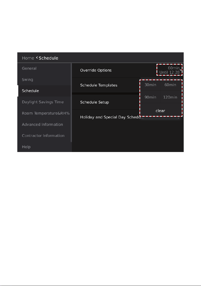
Override Scheduled Settings
Set the system to operate according to the current settings rather than the weekly schedule settings
for a period of time.
Tap the drop-down button on the right of Override Options to set the Override delay time. The Override time can be set to 30, 60, 90, or 120 minutes.
Clear will clear the set time.
After setting, the currently selected delay time is displayed to the right of Override Options.
Figure 60. Override Scheduled Settings
50
Page 51
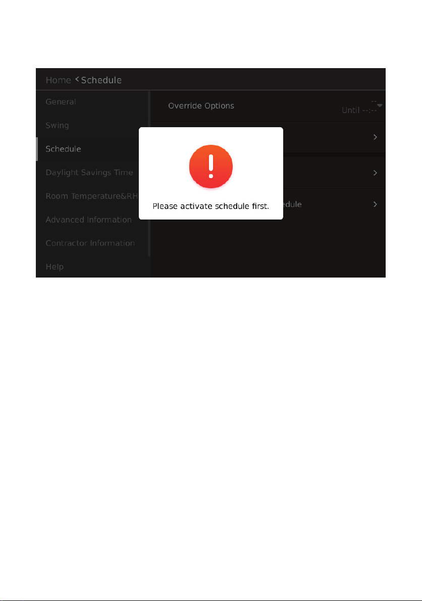
The Override function is only active when the weekly schedule function is enabled. If the weekly
schedule is inactive and the Override time is selected, the prompt box “Please activate schedule
rst” will display.
Figure 61. Activate Schedule Before Overriding Scheduled Settings
51
Page 52
General Settings Conguration
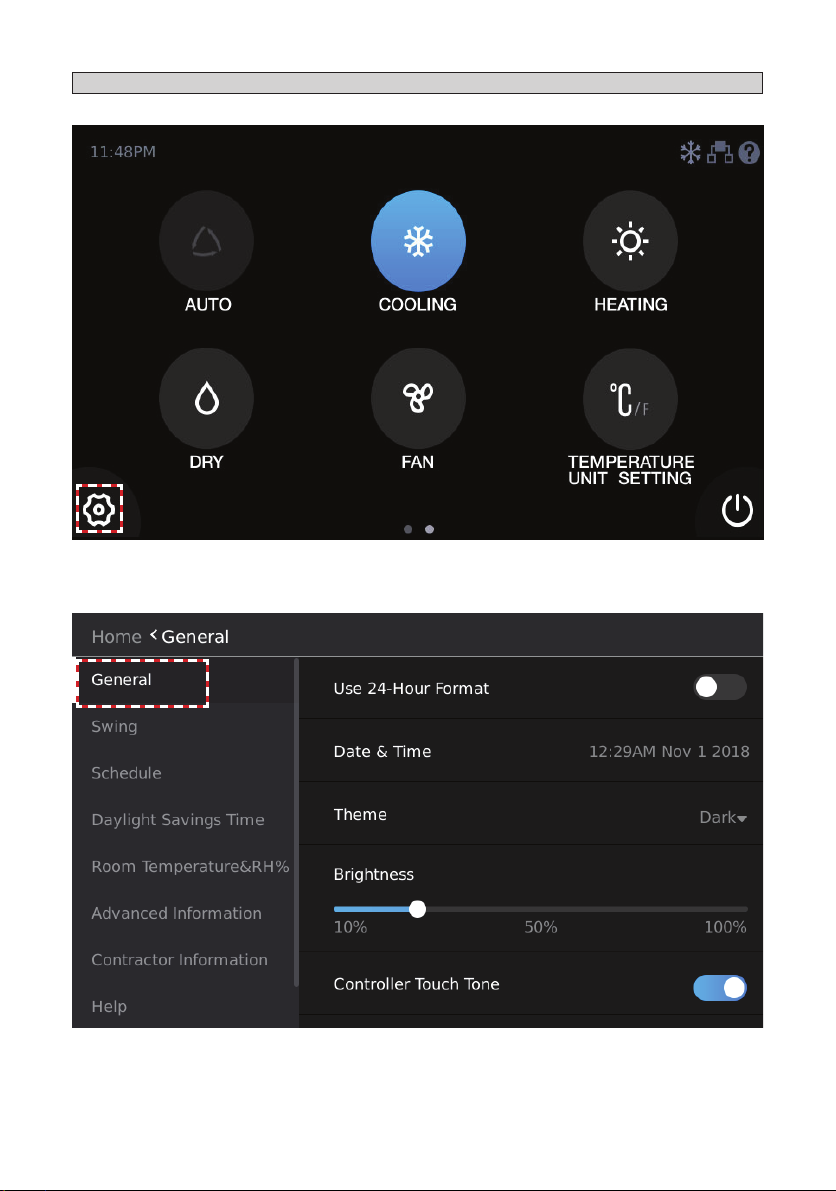
Tap the Settings icon on the main interface to enter the Settings interface.
Figure 62. Access the Settings Interface
Tap the General button to enter the wired controller settings interface.
Figure 63. General Settings Screen
52
Page 53

Time Format Settings
Slide or tap the button on the right of Use-24-Hour Format to switch between 12 hour and 24 hour
clock display.
Figure 64. Time Format Settings
Time Settings
Tap the area to the right of Data & Time, and the time settings box will display. Slide up/down in the
corresponding position to increase/decrease the value and change the time. The highlighted value
in the middle is the currently set parameter.
Figure 65. Time Settings
53
Page 54
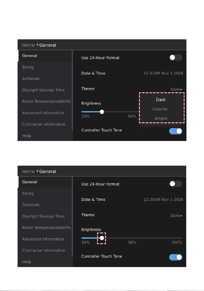
Theme Settings
Tap the drop-down symbol on the right of Theme and select a theme from the selection box that
displays.
There are three themes: Dark, Colorful and Simple.
Figure 66. Theme Settings
Brightness Settings
Slide the button below Brightness to complete the brightness modication.
The brightness range is 10%-100%.
Figure 67. Brightness Settings
54
Page 55
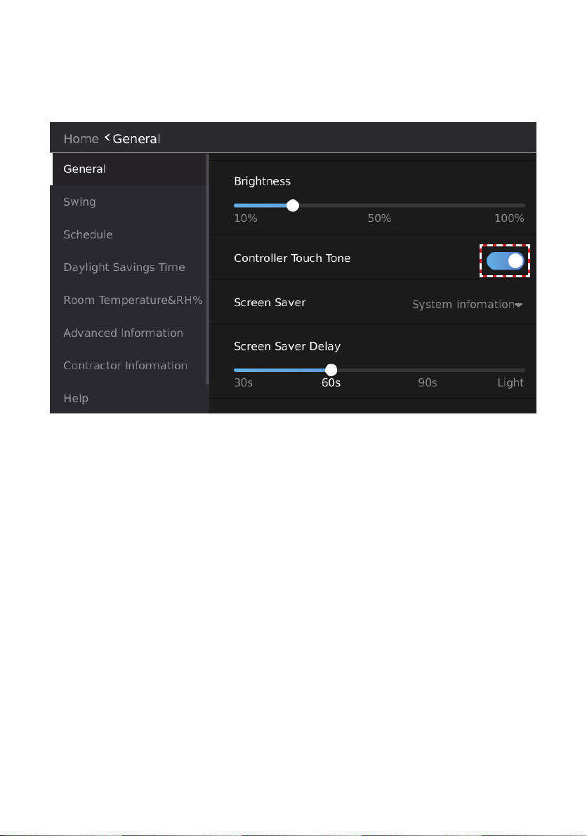
Controller Touch Tone (Sound) Settings
Slide or tap the button on the right of Controller Touch Tone to select whether the controller touch
tone is active.
When the touch tone is inactive, neither the controller nor the indoor unit will beep when a command is sent to the indoor unit.
Figure 68. Touch Tone (Sound) Settings
55
Page 56
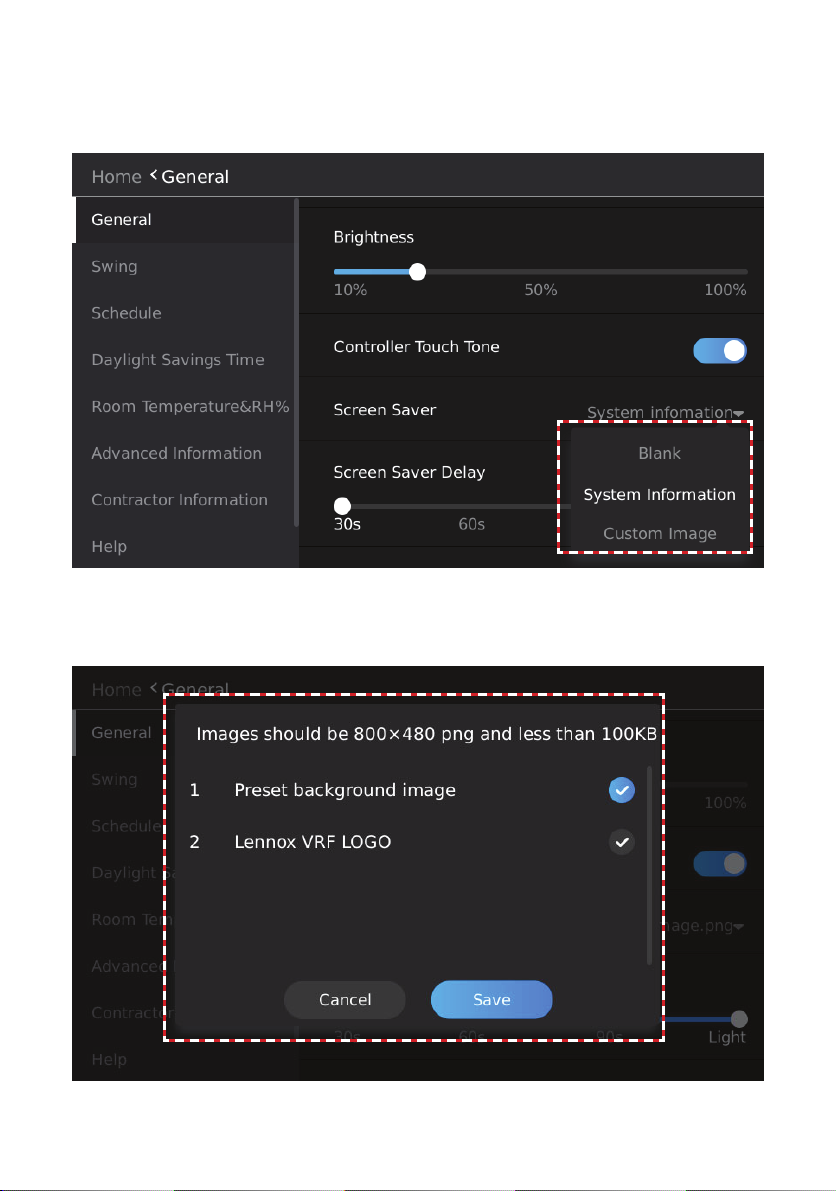
Standby Interface (Screen Saver) Settings
Tap the drop-down symbol on the right of Screen Saver and select a standby screen in the selection box that appears.
The standby screen can be set to Blank, System Information, or Custom Image.
Figure 69. Standby Interface (Screen Saver) Settings
When you select the Custom Image theme, the box for selection of pictures on the USB will
display. You can then select the custom picture to use.
Tap Save to save the theme settings, or tap Cancel to return to the previous interface.
Figure 70. Select Custom Image
56
Page 57

NOTE - Custom image resolution is 800*480, in .png format, and the size must not exceed 100
KB.
Standby (Screen Saver) Duration Settings
Slide the button below Screen Saver Delay and select a time period after which the system enters
the standby interface when no operation is made.
Figure 71. Standby (Screen Saver) Duration
57
Page 58

Swing Angle Settings
Tap the Swing button to enter the swing angle settings interface.
Slide the Vertical button and select the angle of vertical swing.
Click the Horizontal button to select whether to enable horizontal swing.
Figure 72. Swing Settings
Daylight Savings Time Settings
Tap the Daylight Savings Time button to enter the daylight savings time setting interface.
Figure 73. Daylight Savings Time Settings
58
Page 59

Slide or tap the button on the right of Daylight Savings Time and select ON or OFF for daylight
savings time.
Tap the time zone on the right of Start and select the starting time of the daylight savings time.
Figure 74. Select Start Date and Time
Slide the date that needs to be modied up or down. The highlighted value in the middle is the
currently set parameter.
Figure 75. Select Start Date and Time
59
Page 60

Tap the time zone on the right of End and select the ending time of the daylight savings time.
Figure 76. Select Daylight Savings Time Start Date and Time
Slide the date that needs to be modied up or down. The highlighted value in the middle is the
currently set parameter.
Figure 77. Select Daylight Savings Time End Date and Time
60
Page 61

Room Temperature and Humidity Display Settings
Tap the Room Temperature&RH% button to enter the temperature and humidity display settings
interface.
Figure 78. Room Temperature & Relative Humidity (RH) % Settings
Tap the ºC/ºF button on the right of Temperature Unit to switch the temperature units.
Tap or slide the button on the right of Display Space Temperature On Homepage to choose
whether the main interface displays the temperature value.
Tap or slide the button on the right of Display RH% On Homepage to select whether the home
page displays the humidity value.
Figure 79. Room Temperature & Relative Humidity (RH) % Settings
61
Page 62

Contractor Information Input
Tap the Contractor Information button to enter the contractor information input interface.
Figure 80. Contractor Information
Type the information you want to display using the input information interface.
Tap YES to nish information input, or tap NO to return to the previous page.
Figure 81. Enter Contractor Information
62
Page 63

Service Menu
Access Service Menu
• Tap the Service Menu button to enter the password entry interface.
• Tap the corresponding number buttons to enter the correct service password.
• During password entry, tap the backspace key “←” to delete information.
• Tap X to clear all input information.
• The user password can be changed on the Lock screen within the Service Conguration Op-
tions. The default password is 0000.
Figure 82. Access Service Menu
63
Page 64
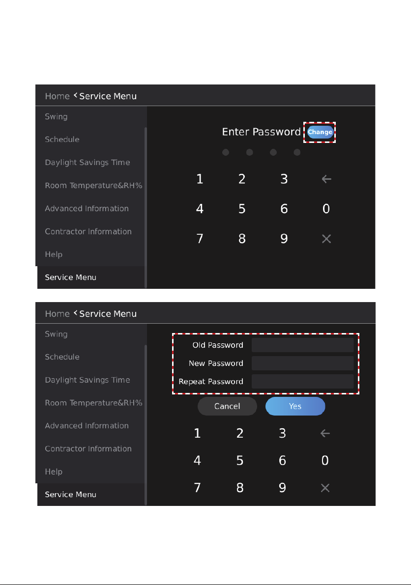
Change Password
1. Tap the Change button to enter the password modication interface. Tap the corresponding
number buttons and enter the old password once, and the new password twice.
2. Tap YES to conrm the password modication, or tap Cancel to exit the password modica-
tion interface.
Figure 83. Change Password
Figure 84. Enter New Password
64
Page 65

Master / Sub Wired Controller Settings
1. Tap the Master/Sub button to enter the Master / Sub wired controller setting screen.
2. Tap the Master or Sub button to identify the wired controller as a master/Sub controller.
3. Tap the Change button, and then the Restart the system to implement the change box will
display. Tap “ok”. The settings will be applied and the wired controller will restart automatically.
NOTE - Only one master controller is allowed in each group of indoor units.
Figure 85. Identify Controller as Master or Sub
65
Page 66

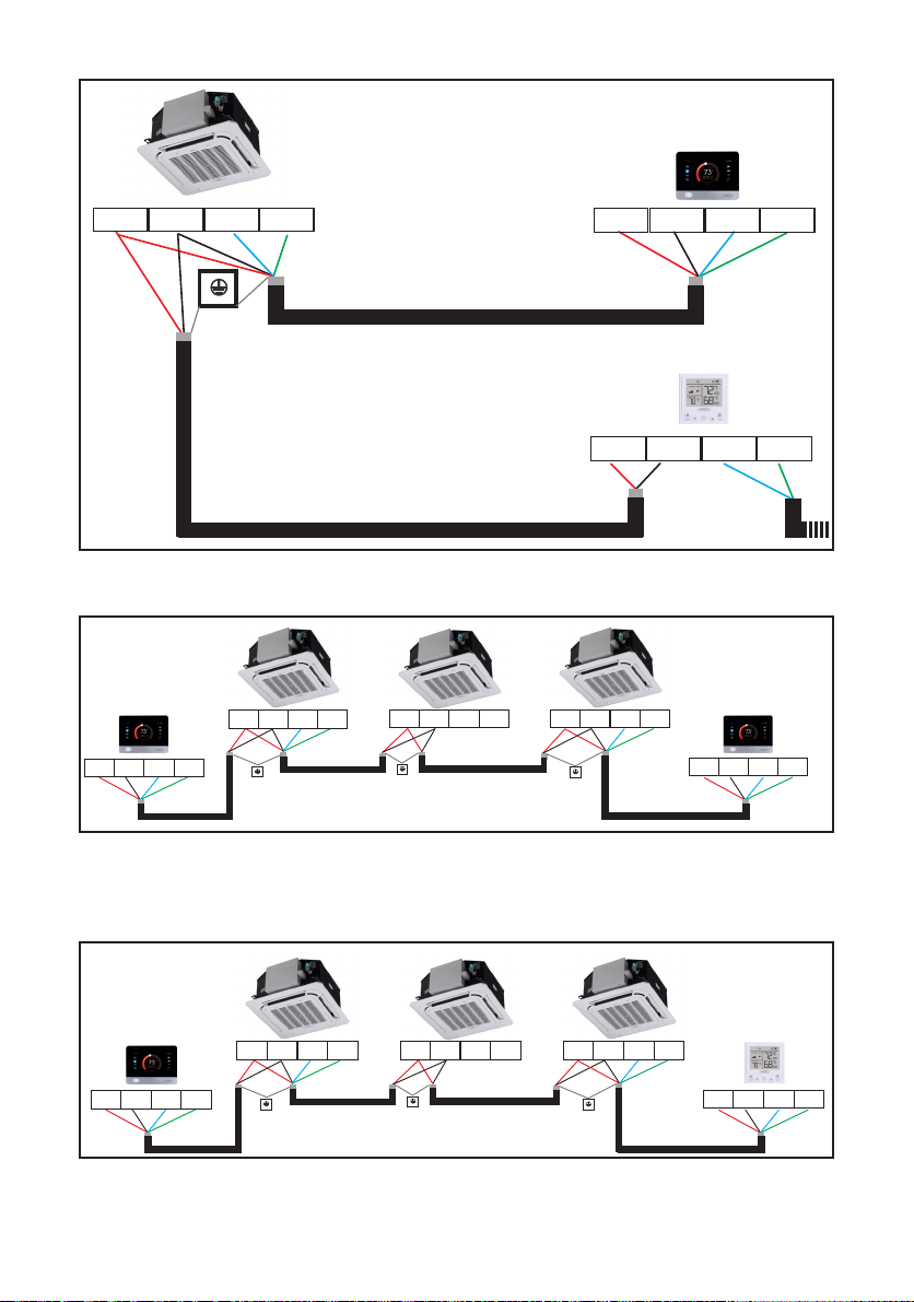
Master / Sub Wired Controller Operation
Up to two controllers can be connected to an indoor unit or group of indoor units. When two controllers are connected, one controller is the master controller and one is the sub controller for that
indoor unit or group of indoor units.
Both the master and sub controller can change the indoor unit’s operation. Other functionality is
limited to the master controller.
Table 4. Master/Sub Controller Operation of Indoor Unit
Function
ON/OFF Yes Yes Yes
Mode(Auto/Cooling/
Heating/Dry/Fan
Fan Speed Yes Yes Yes
Setpoint Yes Yes Yes
Swing Ye s Ye s Ye s
Schedule (including
holidays)
Override Yes No No
Temperature Unit Display Setting (°F/°C)
Setpoint Limit Yes No No
Master Controller
Available
Yes Yes Yes
Yes No No
Yes No No
Sub Controller
Available
Synchronize
Controller Display
HA
HB
COM
12V
HA
HA
Figure 86. Master/Sub Conguration: V0STAT51 Master & V0STAT51 Sub
66
HB
HB
COM
COM
12V
12V
Page 67
HA
HB
COM
12V
HA
HA
Figure 87. Master/Sub Conguration: V0STAT51 Master & V0STAT54 Sub
HB
HB
COM
COM
12V
12V
12V
HB
HA
COM
HA
12V
COM
HB
HA
12V
COM
HB
HA
12V
COM
HB
HA
12V
COM
HB
Figure 88. Master/Sub Conguration: Multiple Indoor Units Connected
V0STAT51 Master & V0STAT54 Sub
12V
HB
HA
COM
HA
12V
COM
HB
HA
12V
COM
HB
HA
12V
COM
HB
HA
12V
COM
HB
Figure 89. Master/Sub Conguration: Multiple Indoor Units Connected
V0STAT51 Master & V0STAT54 Sub
67
Page 68
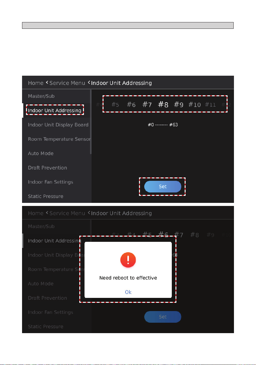
Indoor Unit Address Settings
1. Tap the Indoor Unit Addressing button on the screen to enter the Indoor unit address settings
screen.
2. Slide the number left and right, and select the address value that you want to assign to the
connected indoor unit.
3. Tap the Set button, and then the Need reboot to eective dialog will display.
4. Tap Ok. The settings will take eect and the wired controller will restart automatically.
NOTE - Requires a one-to-one connection to the indoor unit.
Figure 90. Assign Indoor Unit Address
68
Page 69
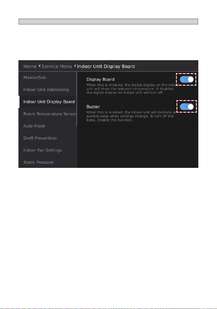
Indoor Unit Display Board & Buzzer (Sound) Settings
1. Tap the Indoor Unit Display Board button to access the Indoor unit display board and buzzer
settings screen.
2. Slide or tap the button on the right of Display Board to select whether to enable the display
function of the indoor unit display board.
3. Slide or tap the button on the right of Buzzer to select whether to enable the buzzer (sound)
function of the indoor unit display board.
Figure 91. Indoor Unit Display & Buzzer (Sound) Settings
69
Page 70
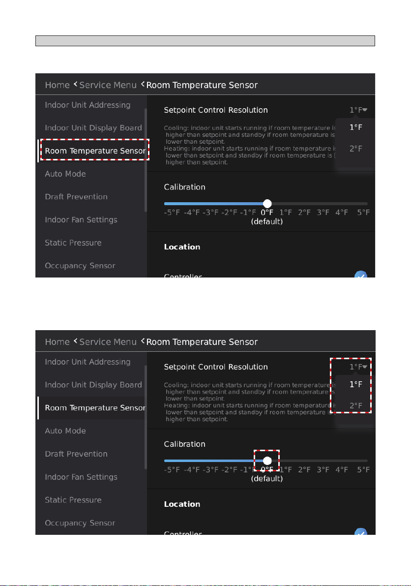
Room Temperature Sensor Settings
1. Tap the Room Temperature Sensor button to access the room temperature sensor settings
screen.
Figure 92. Room Temperature Sensor Settings
2. Tap the drop-down button on the right of Setpoint Control Resolution and select the return
dierence temperature.
3. Slide the Calibration button and select the room temperature calibration value.
Figure 93. Room Temperature Control Resolution & Calibration
70
Page 71
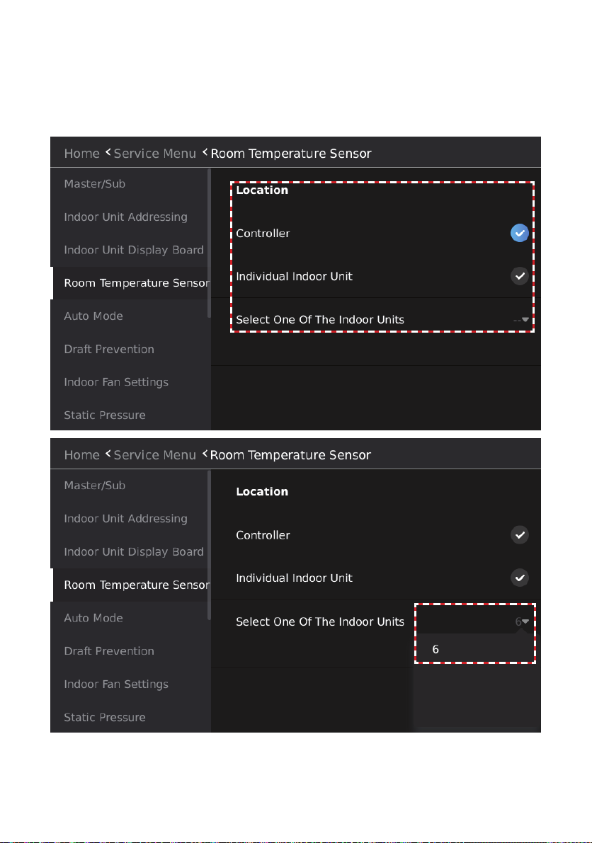
Tap the button below Location and select the Return Air (T1) temperature sensor location.
Controller. Use the controller’s T1 (return air) sensor for all connected indoor units.
Individual Indoor Unit. All connected indoor units will use their own T1 (return air) sensor.
Select One Of The Indoor Units. All connected indoor units will use the T1 (return air) sen-
sor of the selected indoor unit. Tap the drop-down button on the right and select the address
of indoor unit.
Figure 94. Select Return Air Sensor Location
71
Page 72
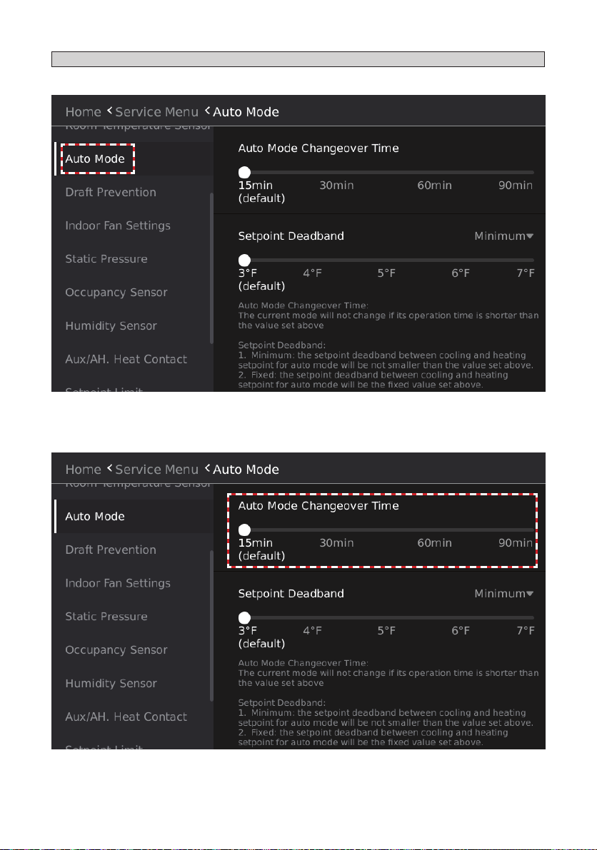
Auto Mode Settings
• Tap the Auto Mode button to access the room auto mode settings screen.
Figure 95. Auto Mode Settings
• Slide the button below Auto Mode Changeover Time and select the auto mode changeover
time.
Figure 96. Auto Mode Changeover Time
72
Page 73
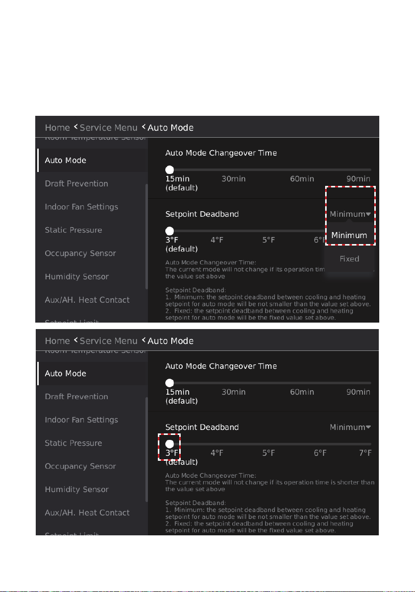
• Tap the drop-down button on the right of Setpoint Deadband and select the method for setting
the temperature dierence between the cooling setpoint and heating setpoint in Auto mode.
• When the Setpoint Deadband in Auto mode is set to Minimum, the temperature dierence
between the cooling setpoint and the heating setpoint is set to a minimum value.
• When the Setpoint Deadband in Auto mode is set to Fixed, the temperature dierence be-
tween the cooling setpoint and the heating setpoint is set to a xed value.
• Slide the button below Setpoint Deadband and select the dierence between the setpoint for
auto mode in cooling and the setpoint for auto mode in heating.
Figure 97. Auto Mode Setpoint Deadband
73
Page 74

Draft (Cold Blow) Prevention Settings
Set the temperature the coil must reach before the fan engages to prevent cold air from being
distributed from the indoor unit.
1. Tap the Draft Prevention button to enter the cold air prevention temperature settings page.
2. Slide the temperature selection button and select the cold air prevention temperature set
value.
Figure 98. Draft (Cold Blow) Prevention
74
Page 75

Stand-by Fan Speed Settings
Set the indoor unit fan operation when the indoor unit setpoint is satised.
1. Tap the Indoor Fan Settings button to enter the stand-by fan speed settings interface.
2. Slide the button below Cooling and select the fan status setting when the cooling setpoint is
satised.
3. Slide the button below Heating and select the fan status setting when the heating setpoint is
satised.
Figure 99. Indoor Fan Settings
75
Page 76

Indoor Unit Static Pressure Settings
Set the indoor unit static pressure. Ducted units only.
1. Tap the Static Pressure button to enter the static pressure settings screen.
2. Slide the static pressure selection button and select the static pressure setting.
NOTE - Requires a one-to-one connection to the indoor unit.
Figure 100. Static Pressure Settings
76
Page 77

Occupancy Sensor Function Settings
Setup the controller’s occupancy sensor.
1. Tap the Occupancy Sensor button to access the occupancy sensor function settings screen.
2. Slide the button on the right of Occupancy Sensor to select whether to enable the occu-
pancy sensor function.
3. Slide the button below Delay to select the duration of the detection of the unoccupied status.
4. Slide the button below Unoccupied Setpoint Oset and select the temperature change value
when unoccupied status is detected.
5. Tap the drop-down button on the right of Heating Set Back and select the temperature limit
to enter the set back operation period.
Figure 101. Occupancy Sensor Function Settings
77
Page 78

Dry Mode Settings
Setup humidity sensing from the controller.
1. Tap the Humidity Sensor button to enter the auto dry mode settings screen.
2. Slide the button on the right of Auto Dry and choose whether to enable the Auto Dry function.
3. Slide the slider on the right of Dehumidier Contact and select whether to install the dehu-
midier in the indoor unit.
4. Slide the value below Target RH% to set the indoor target humidity. The highlighted value in
the middle is the current set parameter.
5. Slide the number below Cuto to set the limit when the Cuto dehumidication operation
temperature is lower than the set temperature. The highlighted value in the middle is the
currently set parameter.
Figure 102. Occupancy Sensor Function Settings
78
Page 79

Auxiliary / Alternate Heat Settings
Setup auxiliary and alternate heat source activation from the controller.
1. Tap the Aux/AH. Heat Contact button to access the auxiliary heat source function settings
page.
2. Select the button on the right of No Auxiliary/Alternative Heat Installed, Aux/Alt Heat Installed
at IDU or in Duct or Other Aux/Alt Heat Installation and conrm the installation method of the
auxiliary heat source.
Figure 103. Auxiliary / Alternate Heat Settings
79
Page 80
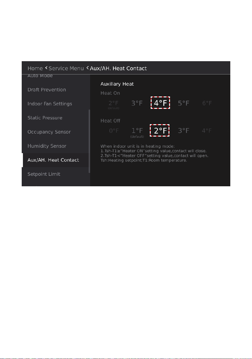
3. Slide the Heat On temperature value below Auxiliary heat. The highlighted value in the
middle is the currently selected parameter. This means that when the indoor ambient tem-
perature is Δt1 lower than the set temperature, the external heat source is turned on.
4. Slide the Heat O temperature value below Auxiliary heat. The highlighted value in the
middle is the currently selected parameter. This means that when when the indoor ambient
temperature is Δt2 higher than the set temperature, the auxiliary heat source is turned o.
Figure 104. Auxiliary / Alternate Heat ON and OFF Settings
80
Page 81
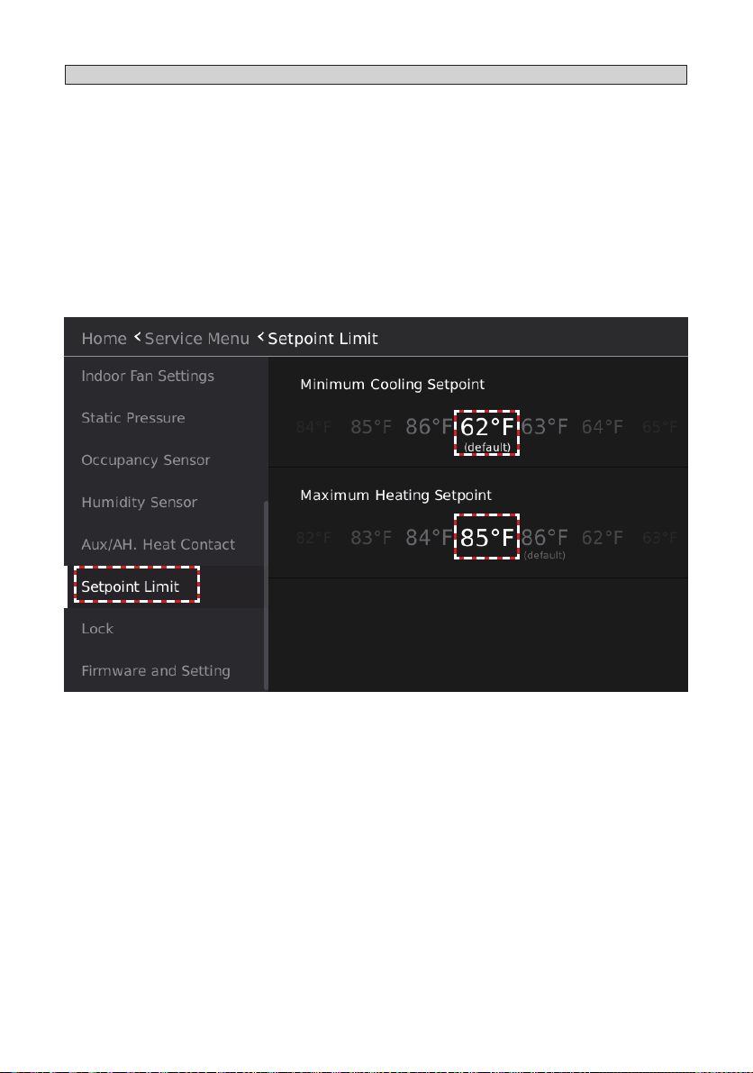
Setpoint Limit Settings
Setup auxiliary and alternate heat source activation from the controller.
1. Tap the Setpoint Limit button to enter the setpoint limit screen.
2. Slide the temperature value below Minimum Cooling Setpoint and select the minimum cool-
ing setpoint. The highlighted value in the middle is the currently selected parameter. After
setting the minimum cooling setpoint, the user will be unable to set a value lower than this
set value when adjusting the setpoint in Cooling mode and Dry mode, or the cooling setpoint
in Auto mode.
3. Slide the temperature value below Maximum Heating Setpoint and select the maximum of
the heating setpoint. The highlighted value in the middle is the currently selected parameter.
After setting the maximum heating setpoint, the user will be unable to set a value higher
than this set value when adjusting the setpoint in Heating mode, or the heating setpoint in
Auto mode.
Figure 105. Setpoint Limit Settings
81
Page 82

Locking Function Settings
Lock the button operation of the controller to prevent the user from adjusting the controller.
1. Tap the Lock button to access the locking function settings screen.
2. Slide the button on the right of ON/OFF, Mode, Temperature Setpoint, Schedule, Horizontal
Louver or Vertical Louver to select whether to lock the parameter.
NOTE - When functionality is locked, the Lock icon will display on the Home screen.
Figure 106. Locking Function Settings
Table 5. Lock Functions
Locking Type Description
ON/OFF Lock the ON/OFF button operation of the wired controller.
Mode Lock the operation mode button operation of the wired controller.
Temperature
Setpoint
Lock the set temperature adjustment button operation of the wired controller.
Schedule Lock the weekly schedule operation parameter.
Horizontal Louver Lock the vertical swing button operation of the wired controller.
Vertical Louver Lock the horizontal swing button operation of the wired controller.
82
Page 83
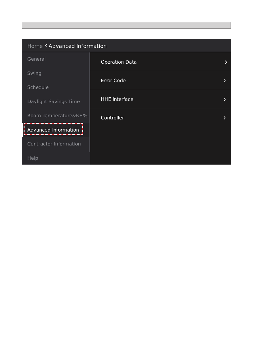
Advanced Information
Tap the Advanced Information button to access the indoor unit information query interface.
Figure 107. Advanced Information
83
Page 84
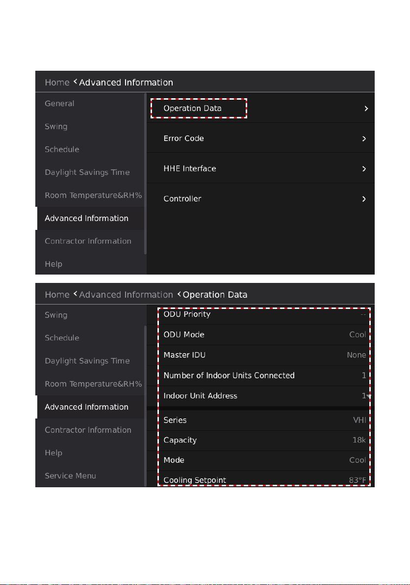
Device Operation Information Query
Tap the Operation Data button on the screen to enter the system operation information query
interface.
Figure 108. Operation Data Query
84
Page 85
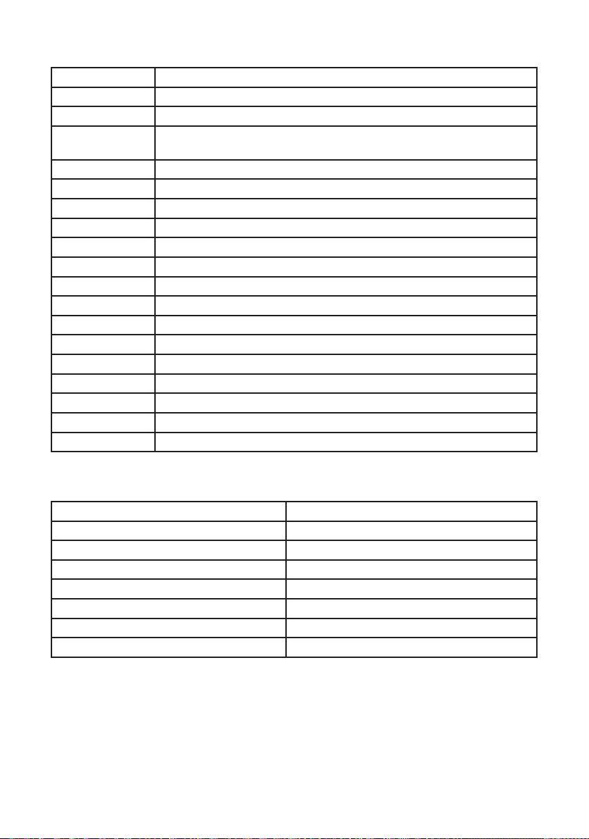
Table 6. System Operation Information Queries
Item Description
ODU Priority Auto/Cool/Heat/VIP/Heat Only/Cool Only
ODU Mode Cool/Heat/Fan/Force Cool/OFF
Master IDU Show VIP indoor unit address; "None" is displayed when there is no VIP
Indoor unit.
Indoor quantity Show the number of connected Indoor Units
Address Indoor unit address (can be selected if there are multiple indoor unit)
Series Indoor unit type
Capacity Indoor unit capacity
Mode Indoor unit (operation) mode
Cooling setpoint The cooling setpoint
Heating setpoint The heating setpoint
T1-In Use Indoor temperature used by the system
T1-IDU Temperature value collected by the Indoor Unit’s own sensor
T2 Evaporator middle temperature
T2A Evaporator inlet temperature
T2B Evaporator outlet temperature
EEV EXV opening
Fan speed Fan (operating fan speed) speed
Software version Indoor Unit software version number.
Table 7. Indoor Unit Types
Indoor Unit Type Model Number
360° Cassette V33
Wall-Mounted VWM
Medium Static Concealed Ducted VMD
Vertical Air Handler VVC
High Static Concealed Ducted VHI
Compact 360° Cassette V22
Ceiling Floor Convertible VCF
85
Page 86

Device Operation Error History Query
Check the error information of the system to which the wired controller is connected.
Tap the Error Code button to enter the system error information query interface.
Figure 109. Error Code History Query
86
Page 87

Table 8. Error Code Information
Indoor Unit Type Model Number
No. Serial number.
IDU# Address of the faulty indoor unit. If the error is related to the outdoor unit,
MS box or controller “- -“ is displayed.
Error Error code number. Use this number to look up the error in the VRF app.
Type IDU - Indoor unit, ODU - Outdoor unit, CTRL - Controller. Identies what
equipment type is faulty.
Time Date and time of the error.
87
Page 88
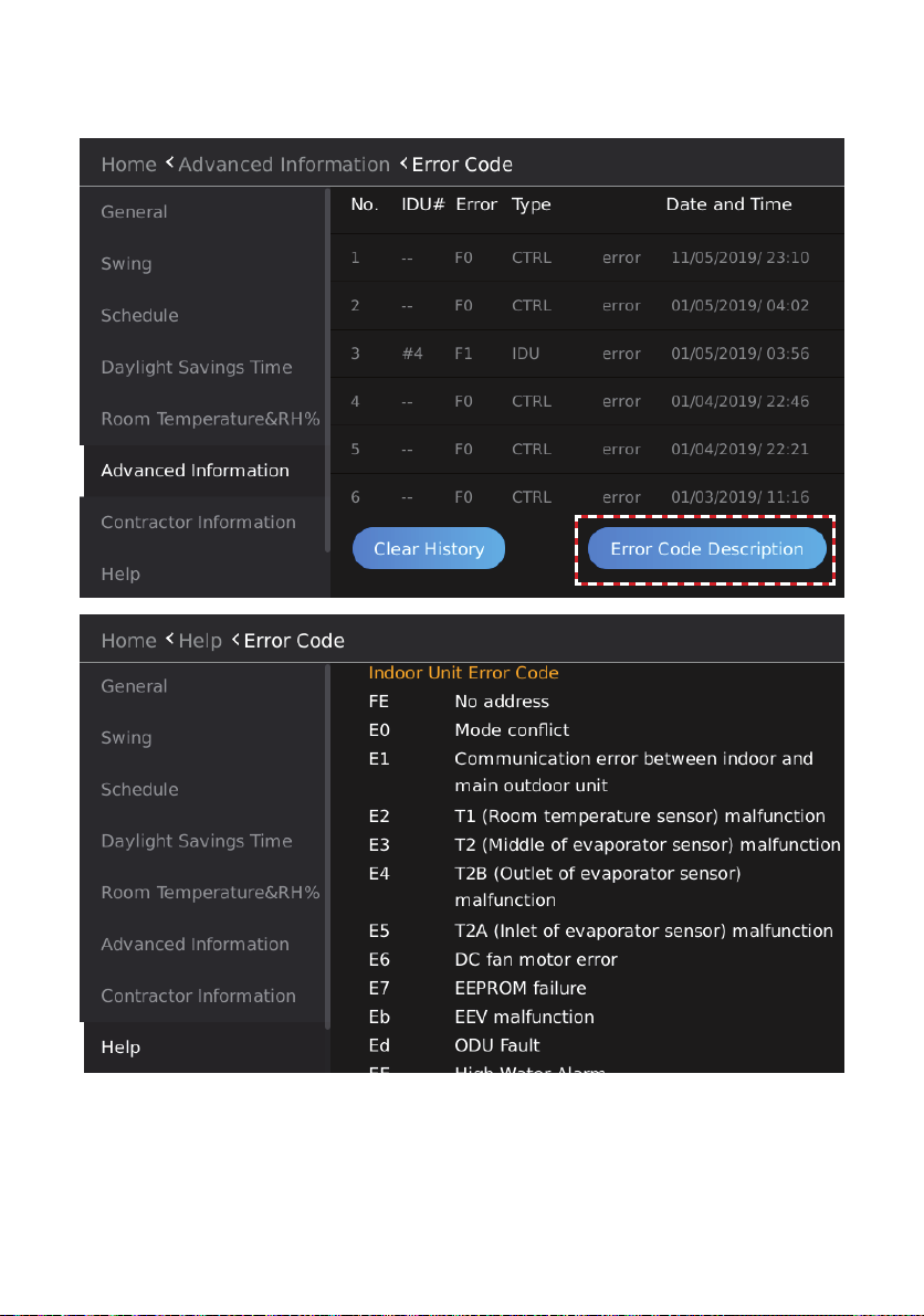
Tap the Error Code Description button to enter the error code details screen.
Detailed error code analysis and fault nding information is available in the Lennox VRF app.
Figure 110. Error Code Descriptions
88
Page 89
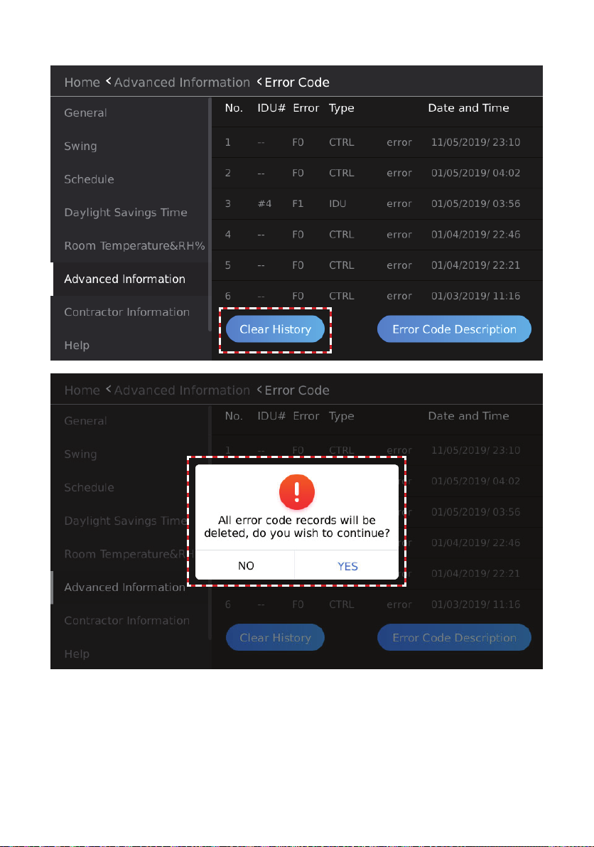
Tap the Clear History button to delete the error code history from the controller.
Figure 111. Clear Error Code History
89
Page 90

HHE Dry Contact Relay Interface Status Query
Tap the HHE Interface button to access the HHE relay query interface.
Figure ##. Access HHE Dry Contact Relay Interface
Tap the drop-down button on the right of the Indoor Unit Address, and select an indoor unit address
to query the status of dry contacts.
Figure 112. View HHE Dry Contact Relay Information
90
Page 91

Controller Information
Tap the Controller button to access the controller information interface.
Figure 113. Controller Information
91
Page 92

Firmware and Setting Information
Tap the Firmware and Setting button to access the Software Update and Firmware screen.
Figure 114. Access Firmware and Settings
CAUTION
DO NOT turn o power to the indoor
unit or the controller during the software
update process. Damage to indoor unit and
controller boards may occur.
IMPORTANT
After initial setup, make a back up copy
of the controller settings by following the
instructions on page 97. Store the copy on
a large capacity ash drive for permanent
storage. This ensures the controller can be
reset to initial settings if needed.
92
Page 93

Software Version
Tap the Firmware and Setting button to access the software update screen.
Figure 115. Access Software Update & Version Information
The software update screen displays the current version of the wired controller software.
Figure 116. Software Version
93
Page 94
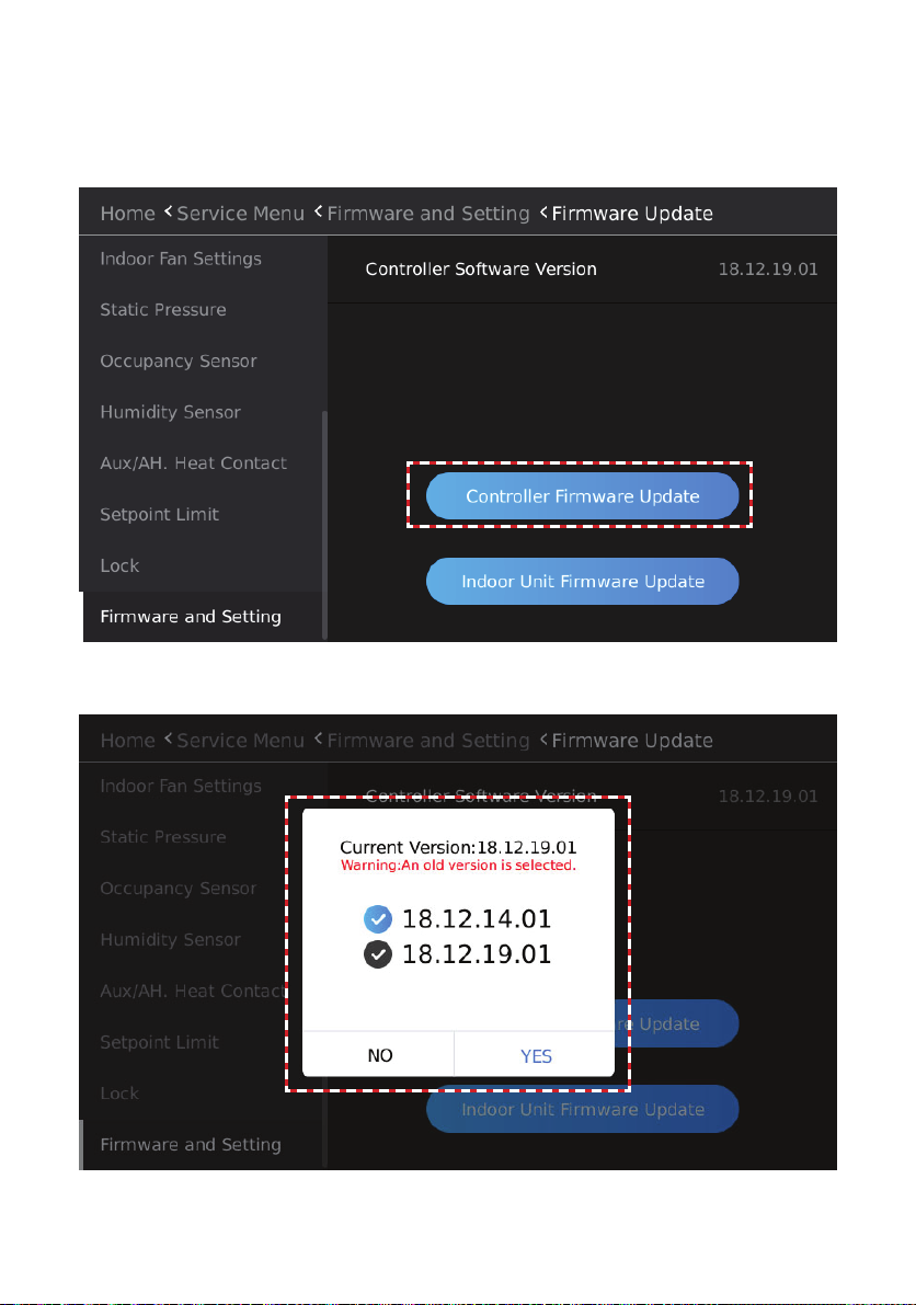
Controller Software Update
1. Insert the USB containing the software update les into the USB port on the bottom of the
controller.
2. Tap the Controller Firmware Update button, and a list of software installed in the USB device
will display.
Figure 117. Controller Software Update
3. Select the controller software version number to upgrade.
Figure 118. Available Controller Software Update Files
94
Page 95

4. Tap YES to upgrade the controller software. Wait for about 10 seconds. Then the Update
success pop-up window will display. Or, tap NO to return to the previous screen.
Figure 119. Controller Software Update Success!
5. After the controller software upgrade, the Reboot the system to nish the update prompt box
will display. Tap YES to restart the system, or tap NO to return to the previous interface.
Figure 120. Reboot After Controller Software Update
95
Page 96
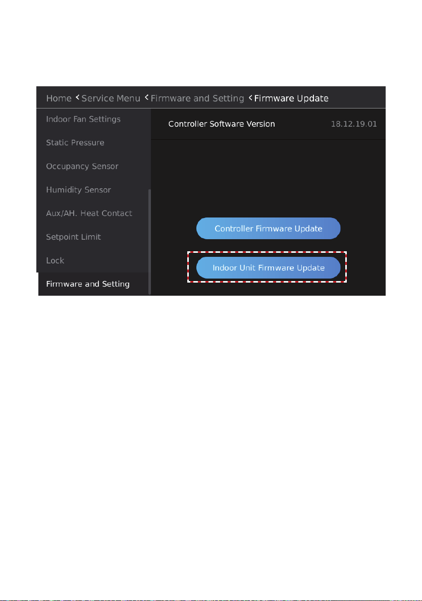
Indoor Unit Software Update
Update the connected indoor unit software; requires one-to-one connection between indoor unit
and controller.
1. Insert the USB containing the software update les into the USB port on the bottom of the
controller.
Figure 121. Indoor Unit Software Update
96
Page 97
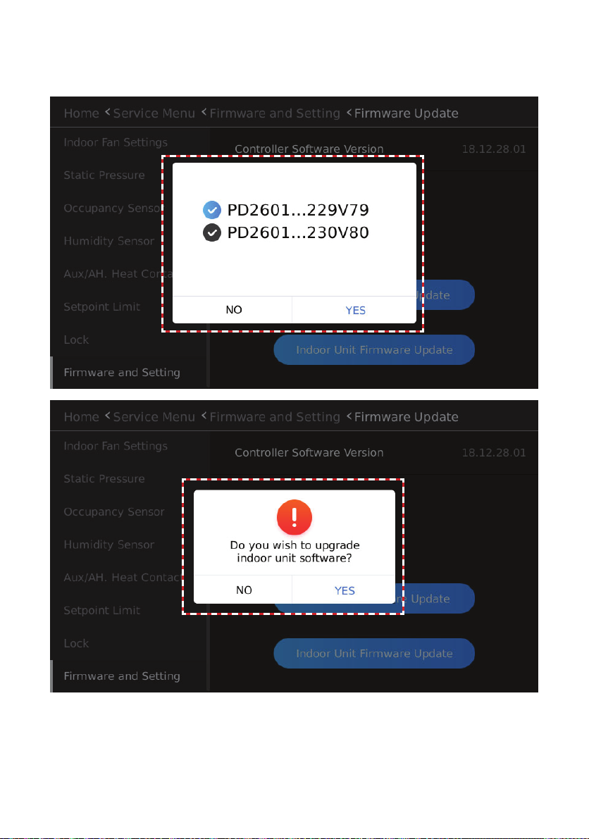
2. Tap the Indoor Unit Firmware Update button, and a list of software installed in the USB
device will display.
3. Select the indoor unit software version number to upgrade.
Figure 122. Indoor Unit Software Update File Selection
97
Page 98
4. Tap YES, and then the Do you wish to upgrade indoor unit software? pop-up window will
display. Or, tap NO to return to the previous screen.
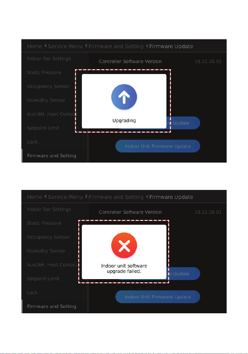
5. The Upgrading software notication will display until the update is complete.
Figure 123. Indoor Unit Software Update In Progress
If the software upgrade is unsuccessful, the notication Indoor unit software upgrade failed. will
display.
Figure 124. Indoor Unit Software Update Failure
98
Page 99
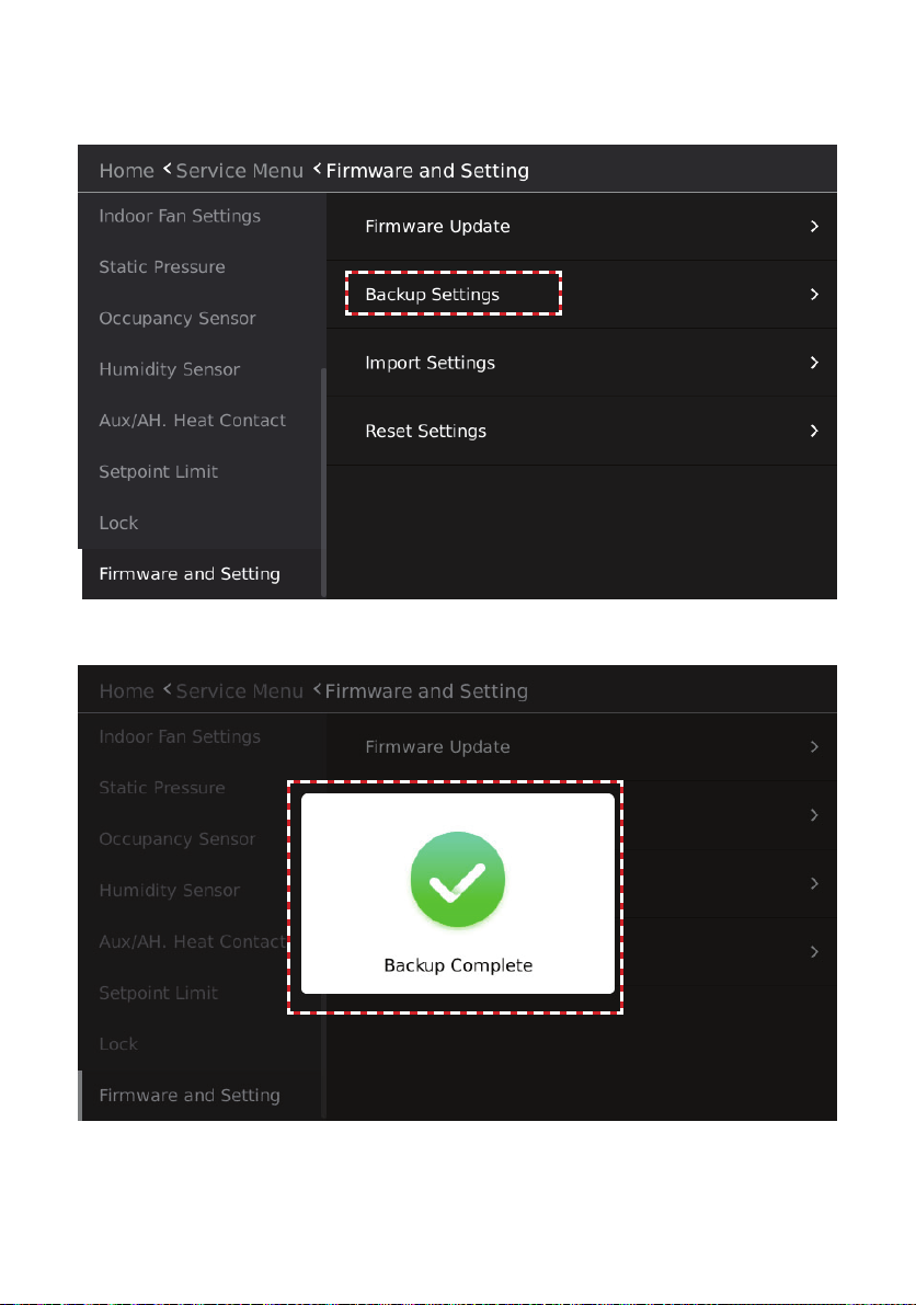
Setting Parameters Backup
Tap the Backup Settings button to export parameters for the general function settings and advanced settings of the wired controller to the connected USB device.
Figure 125. Backup Controller Settings
The Backup Complete pop-up window displays after the setting parameters have been exported.
Figure 126. Backup Complete Notication
99
Page 100
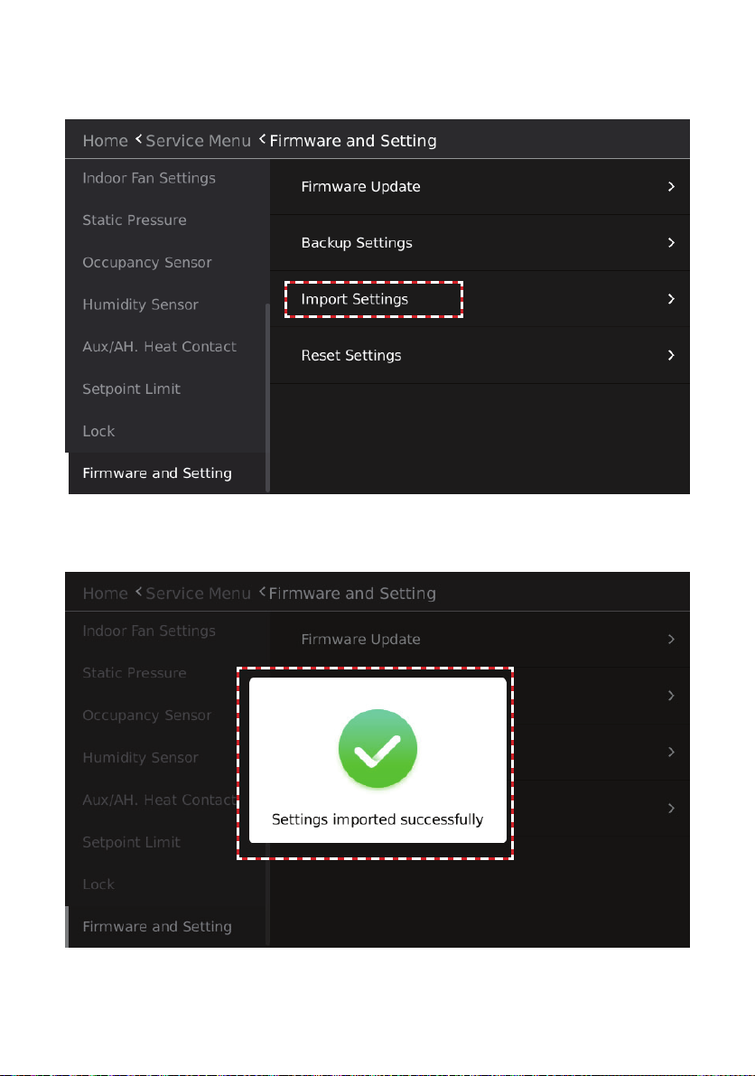
Setting Parameters Import
Tap the Import Settings button to import parameters for the general function settings and advanced settings of the wired controller from the connected USB device.
Figure 127. Import Controller Settings
The Settings imported successfully pop-up window displays after the setting parameters have
been exported.
Figure 128. Import Successful Notication
100
 Loading...