

Page 1

1
©2018 Lennox Industries Inc.
Dallas, Texas, USA
INSTALLATION/
OPERATION
INSTRUCTIONS
CONTROLS
507595-05
05/2018
This manual must be left with the
owner for future reference.
WARNING
!
Improper installation, adjustment,
alteration, service or maintenance can
cause property damage, personal injury
or loss of life.
Installation and service must be
performed by a licensed professional
HVAC installer (or equivalent) or service
agency.
V0STAT51P-2 Touch Screen
Programmable Local Controller
General
The V0STAT51P-2 is a wired touch screen
programmable local controller for VRF Heat
Recovery and Heat Pump indoor units with
convenient timed schedules for daily operation.
These instructions are intended as a general
guide and do not supersede local codes in any
way. Consult authorities having jurisdiction before installation.
Shipping and Packing List
Package 1 of 1 contains;
1 – Wired Controller
1 – CR2032 Lithium battery
2 – Phillips screws
2 – Plastic spacers
2 – 1/8” polymer toggle anchors
1 – Installation and operation manual
Requirements
Be sure that power supply has been turned
o before beginning installation. This controller should be used only as described in this
manual.
Tools Needed
#2 Phillips screwdriver
Slotted precision screwdriver
Level
1/8” wall anchor tools
Controller Placement
Avoid installing local controller in high load
or heat loss areas such as exterior walls or
walls that are against unconditioned spaces,
near entry doors and windows, or where direct sunlight may be present.
CAUTION
To ensure proper system performance and
reliability, Lennox does not recommend
operation of VRF systems during any phase
of construction. Construction debris, low
temperatures, harmful vapors, and operation
of the unit with misplaced lters can damage
the units. Failure to follow these guidelines
will result in the warranty being voided.
IMPORTANT
Frequent changes to operating mode
may cause system malfunction. Allow at
least one minute between mode changes
to allow the system to stabilize.
Page 2

2
Contents
General ........................................................................................................................................1
Requirements ..............................................................................................................................1
Shipping and Packing List ..........................................................................................................1
Tools Needed...............................................................................................................................1
Controller Placement ..................................................................................................................1
Installation ...................................................................................................................................3
Connecting to One Indoor Unit ............................................................................................4
Connecting to Multiple Indoor Units ....................................................................................5
Mounting the Controller .......................................................................................................6
Home Screen Display ..................................................................................................................8
Operation ...................................................................................................................................10
Schedule Management..............................................................................................................20
Create or Modify a Schedule .............................................................................................20
Copy and Paste a Schedule ..............................................................................................25
Setup Holidays Schedule ..................................................................................................27
Reset Weekly Timer Parameters .......................................................................................30
Override Function Settings ................................................................................................31
Error Code Display ....................................................................................................................33
Centralized Controller Lock Function ........................................................................................34
General Settings Conguration .................................................................................................36
Set Date ............................................................................................................................37
Set Time ............................................................................................................................38
Enable or Disable the Schedule Function .........................................................................39
Set Daylight Savings Time ................................................................................................40
Set Home Screen Display Type ........................................................................................41
View and Edit Contractor and Controller Information ........................................................42
View Error Code History ....................................................................................................43
Complete List of Error Code Descriptions .........................................................................44
Service.......................................................................................................................................45
Set System Type ...............................................................................................................46
Set Temperature Unit.........................................................................................................47
Set Temperature Setpoint Range ......................................................................................48
Set Fan Control .................................................................................................................49
Adjust Auxiliary / Alternative Heat Settings ........................................................................50
Auxiliary Heat Settings ......................................................................................................51
Alternative Heat Control ....................................................................................................52
Lock Function ....................................................................................................................53
Change User Password for Service Conguration Access ...............................................54
Set Room Temperature Sensor Location ..........................................................................55
Set Room Temperature Sensor Calibration ....................................................................... 56
Set Override Function .......................................................................................................57
Set Louver Swing Function ...............................................................................................58
Congure ERV Settings (Future Revision) ........................................................................59
Advanced Information................................................................................................................60
Indoor Unit Operating Data ...............................................................................................61
Indoor Unit Error Code History ..........................................................................................63
HHE Relay Four Dry-Contact Status .................................................................................64
Firmware and Setting Information .............................................................................................65
Copy/Change Settings or Update Firmware .....................................................................66
Export Settings to USB .....................................................................................................67
Import Settings from USB .................................................................................................68
Update Software ................................................................................................................69
Software Update Best Practices ........................................................................................70
Reset Settings ...........................................................................................................................71
Page 3

3
• This manual provides the installation
instructions for this controller. Refer to the
included wiring diagrams to connect the
controller to the indoor unit.
• The controller uses low voltage. Keep a
minimum distance of 12” (305 mm) between
low voltage control wire and high voltage
power wires.
Power wiring between controller and rst
indoor unit:
• Minimum 18 AWG stranded, shielded cable
up to 164 feet (50 m).
• Ensure there are no gaps between the controller back cover and the mounting surface.
• Fill any holes in the wall behind the control-
ler to avoid false readings from inltration.
• Ground the shielded control wiring.
• Do not use a megger to test insulation.
Communication wiring between indoor
units:
• Minimum 18 AWG stranded, shielded cable.
Installation
CAUTION
!
Do not install controller in areas where
harmful gases containing sulfur or
other damaging agents may exist or the
controller may be damaged.
Clean controller using a clean, damp
cloth. Do not spray cleanser on or around
controller.
Be sure that power supply has been
turned o before beginning installation.
Do not operate controller with wet hands.
WARNING
!
IMPORTANT
Read all of the information in this manual
before using this controller. All wiring must
conform to local and national building and
electrical codes and ordinances. This is a
12 VDC controller. Do not install on voltages
higher than 12 VDC.
IMPORTANT
Electrostatic discharge can aect electronic
components. Take precautions to neutralize
electrostatic charge by touching your hand
and tools to metal prior to handling the control.
Page 4

4
C/
GNDR/12V
X
Y
12V X
Y
E
NOTE - 1. Connect terminal “C/GND” on the controller to terminal “E” on the indoor unit.
2. Ground cable shielding at the indoor unit.
3. Use stranded, shielded, 18 GA cable.
Figure 1. Connect Controller to Single Indoor Unit Wiring Connections
Connecting to One Indoor Unit
Connect the controller to one indoor unit main control board using 4-conductor shielded 18 GA
cable. Connect to terminals X Y C/GND and R/12V. See Figure 1.
Page 5

5
Figure 2. Connect Controller to Multiple Indoor Units Wiring Connections
Connecting to Multiple Indoor Units
Connect the controller to multiple indoor units, up to 16. Use 4-conductor shielded cable to connect
to the rst indoor unit, then daisy chain control wiring to each indoor unit using the XYE terminals
in the electrical control box of the indoor unit. Do not daisy chain 12V power cable. See Figure 2.
NOTE – All of the indoor units connected to the controller must be on the same refrigerant circuit,
connected to the same outdoor unit.
NOTES - 1. Connect “R/12V” on the controller to terminal “12V” on the first indoor unit only. 12V
connection provides power to controller; connection to multiple indoor units will
damage controller and indoor unit boards.
2. Connect terminal “C/GND” on the controller to terminal “E” on the indoor unit.
3. Ground cable shielding at one end of each length of cable, except at controller.
4. Use stranded, shielded, 18 GA cable.
5. Connect up to 16 indoor units.
C/
GNDR/12V
X
Y
12V X
Y
E
12V X
Y
E
12V X
Y
E
CAUTION
Connect “R/12V” on the controller to
terminal “12V” on the rst indoor unit
only. 12V connection provides power to
controller; connection to multiple indoor
units will damage controller and indoor
unit boards.
Page 6

6
Mounting the Controller
1. Remove the back cover from the controller. See Figure 3.
Figure 4. Attach Back Cover to Wall
Figure 3. Remove Back Cover from Controller
2. Attach the back cover to the wall using screws. See Figure 4.
Page 7
7
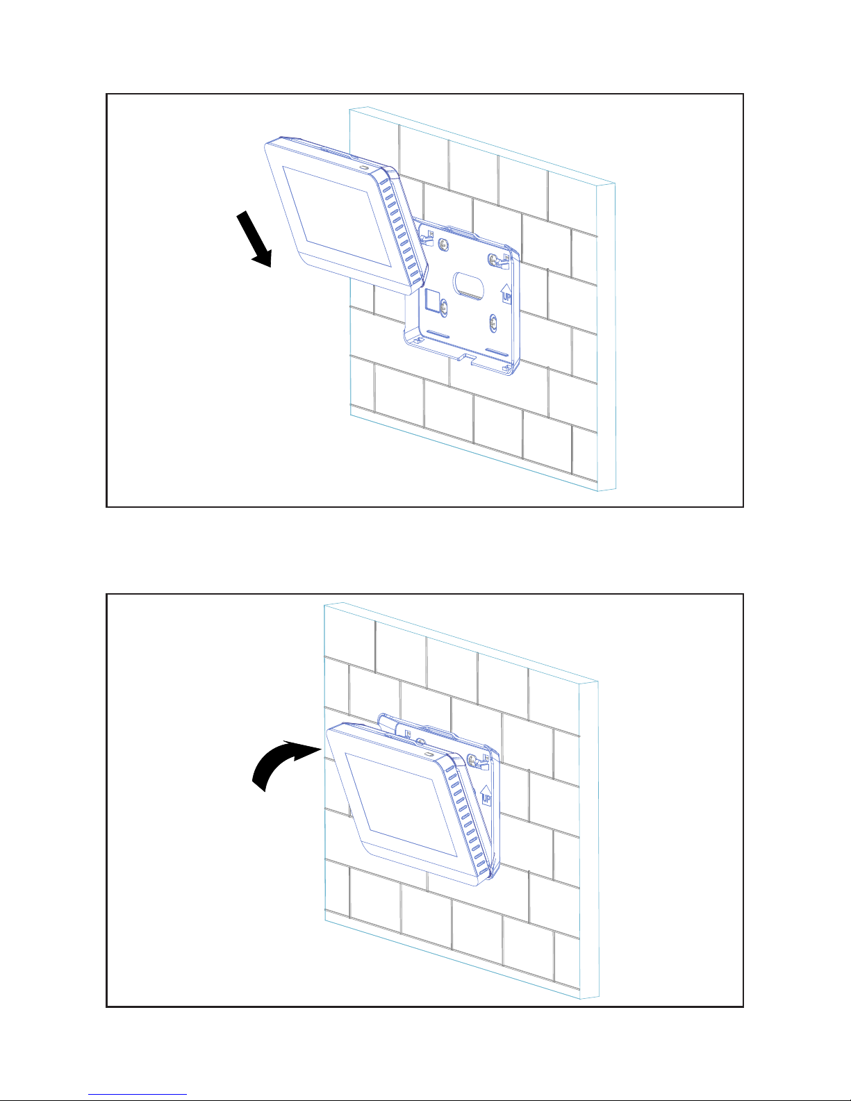
3. Insert the controller into the bottom snap joints of the back cover at an angle. See Figure 5.
Figure 5. Insert Controller into Back Cover
4. Push the controller back toward the wall until it “snaps” into place. See Figure 6.
Figure 6. Snap Controller Into Place
Page 8

8
Home Screen Display
Figure 7. Standard Home Screen Display
Figure 8. Simple Home Screen Display
1
15
14
13
10
2
3
4
5
6
7
8
9
10
2
3
4
5
6
7
8
9
12
11
1
12
11
Page 9

9
Table 1. Home Screen Display
Number Display Item Description
1 ON/OFF button Swipe to turn the indoor unit on or o.
2 Menu button Tap to access the menu screen.
3 Mode buttons Tap to switch the indoor unit operation mode.
4 Temperature Displays the current setpoint setting.
5 Decrease button Tap to lower the temperature setpoint.
6 Temperature slider Drag to change the temperature setpoint.
7 Increase button Tap to raise the temperature setpoint.
8 Fan speed
Tap High, Med, or Low to change the fan
speed
9 Room temperature Displays the room temperature.
10 Date/Time Displays the current date and time
11
Centralized controller
lock icon (not shown)
Indicates that the controller is locked by a
central controller.
12 Lock icon (not shown)
Indicates that the selected function of the
controller is locked.
13 Swing button
Tap to enable or disable the indoor unit automatic louver swing function. Not available
on all indoor unit styles.
14 Schedule
Displays the schedule status. Tap to access
weekly schedule settings.
15 Override
Displays the override status. Tap to access
override settings.
Page 10

10
Operation
ON/OFF. Swipe the On/O slider to turn the indoor unit on or o.
Figure 9. ON/OFF Operation
NOTE - Indoor units connected to a local controller may also be controlled by a centralized controller. Indoor units respond to the last command sent. It is recommended that indoor units be controlled from a single source of control, either local controller or centralized controller but not both,
to avoid conicts in commands.
Page 11

11
Cooling Mode Operation. Tap the Cool button to start cooling operation. The indoor unit will provide cooling operation to maintain the selected setpoint. The default setpoint range is 62°F to 86°F
(17°C to 30°C).
Figure 10. Cooling Mode Operation
Page 12

12
Figure 11. Heating Mode Operation
Heating Mode Operation. Tap the Heat button to start heating operation. The indoor unit will pro-
vide heating operation to maintain the selected setpoint. The default setpoint range is 62°F to 86°F
(17°C to 30°C).
Page 13

13
Figure 12. Auto Mode Operation
Auto Mode Operation. Only available on heat recovery systems. Tap the Auto button to start auto
mode operation. The indoor unit will provide cooling or heating operation as determined by the
room temperature and the setpoint settings. The setpoint range is 62°F to 86°F (17°C to 30°C). The
cooling setpoint must be ≥3° higher than the heating setpoint.
NOTE - During Auto mode, both operation mode (cooling or heating) setpoints display on the Home
screen. The current operation mode setpoint displays larger than the non-current operation
mode.
To adjust the setpoint of either cooling or heating while in Auto mode, tap the appropriate setpoint,
either cooling or heating. That setpoint will display as the larger number. Drag the temperature
slider to the new setpoint temperature. If the setpoint you adjusted is not the current operation
mode, after 10 seconds, the current operation mode setpoint will display as the larger number.
NOTE - A three degree setpoint deadband between cooling and heating setpoints is built in to the
controller.
Page 14
14
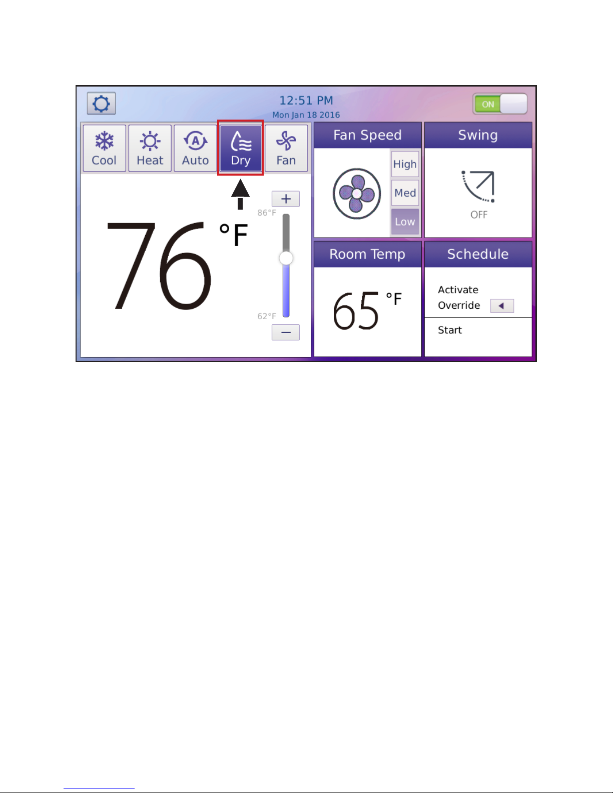
Figure 13. Dry Mode Operation
Dry Mode Operation. Tap the Dry button to start dry mode operation. Fan speed cannot be ad-
justed during dry mode.
Page 15

15
Figure 14. Fan-Only Mode Operation
Fan-Only Operation. Tap the Fan button to start fan-only operation. The indoor unit fan operates
without heating or cooling.
Page 16

16
Fan Speed. Tap High, Med, or Low to change the fan speed.
Figure 15. Fan Speed Operation
Page 17

17
Figure 16. Temperature Setpoint
Temperature Setpoint. Adjust the setpoint of the current mode by dragging the temperature slider
or by tapping the Increase (+) or Decrease (-) buttons. The default setpoint range is 62°F to 86°F
(17°C to 30°C). The setpoint range can be adjusted using the Setpoint Limit screen in the Service
menu.
Page 18

18
Figure 17. Room Temperature
Room Temperature. The room temperature displays on the controller’s main screen. The room
temperature is sensed by the sensor inside the controller (default) or by the indoor unit. Set the
sensor location using the Room Temperature Sensor Location screen in the Service menu.
Page 19

19
Figure 18. Swing
Swing. Tap the Swing button to enable or disable the indoor unit automatic louver swing function.
The swing icon changes to indicate if swing is on or o. Set the louver swing functionality using the
Louver screen in the Service menu. (Not available for all indoor unit types.)
Page 20

20
Schedule Management
Create or Modify a Schedule
1. Tap the Schedule button to access the schedule program.
Figure 19. Tap Schedule Button to access Schedule Program
NOTE – If schedules are used and a centralized controller is installed on the system, controller
functions should not be locked from the centralized controller.
Page 21
21
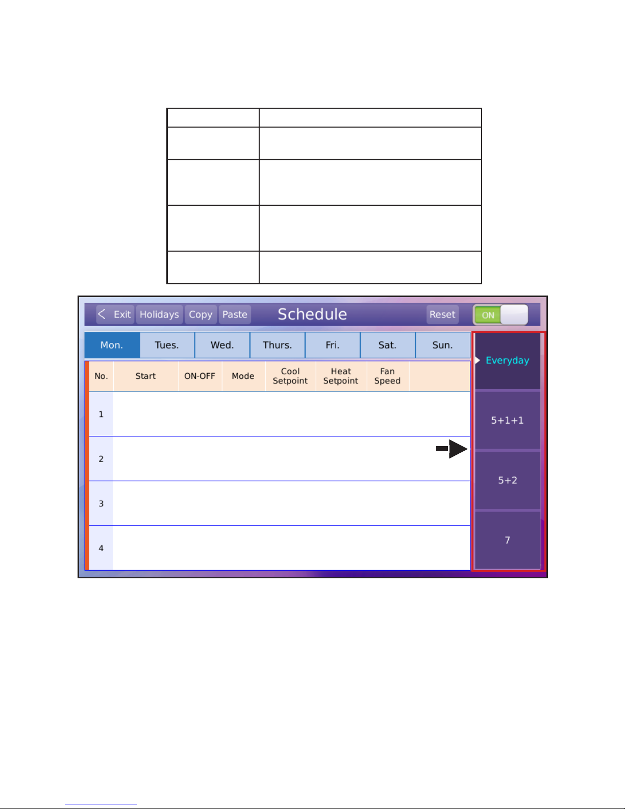
Figure 20. Select Schedule Type
2. Tap the button of the schedule type to setup or edit to select the schedule type. Only one option can be used. See Table 2 for descriptions.
Table 2. Schedule Options
Schedule Description
Everyday
Set the schedule independently for each
day of the week.
5+1+1
Set the schedule uniformly for Monday
through Friday and independently for Saturday and Sunday.
5+2
Set the schedule uniformly for Monday
through Friday and uniformly for Saturday
and Sunday.
7
Set the schedule uniformly for each day of
the week.
Page 22

22
3. Tap the blank space in the grid to set the rst action. A set of default values will display.
Figure 21. Display Timer Information
Page 23

23
Figure 23. Adjust Event Settings
4. Tap the Edit button.
5. Set or modify the event parameters including the action begin time, ON/OFF, mode, cooling
temperature setting, heating temperature setting, and fan speed.
6. Tap the OK button to save the settings.
7. Tap the Delete button to delete the action.
Figure 22. Tap Edit Button
Page 24

24
Figure 24. Edit Schedule Actions/Events
8. Up to 8 timer actions/events can be scheduled for each day.
Page 25

25
Copy and Paste a Schedule
1. Select the day you want to copy and tap the Copy button. A red triangle displays on the day
that is selected for copying.
Figure 25. Select Day to Copy From
Page 26

26
2. Select the day to copy to and tap the Paste button.
Figure 26. Select Day to Copy To
Page 27

27
Setup Holidays Schedule
Holiday scheduling overrides the set schedule settings on those days.
1. Tap the Holidays button to access the holiday schedule settings.
Figure 27. Setup Holidays Schedule
Page 28

28
2. Tap the blank space in the grid and then tap the Edit button.
Figure 28. Edit Holiday Schedule
Page 29

29
3. Tap the By Date button to select the holiday by specic year, month and day. (Ex: 18th Janu-
ary 2016)
4. Select the By Day button to select the holiday by month and week. (Ex: 3rd Monday in January)
5. Tap the OK button to save the holiday schedule settings.
6. Tap the Delete button to delete the active holiday schedule.
Figure 29. Save Holidays Schedule Parameters
Page 30

30
Reset Weekly Timer Parameters
1. Tap the Reset button to permanently delete all schedules. This cannot be undone.
Figure 30. Reset Schedule
Page 31

31
Override Function Settings
Use the override function to override the current schedule for a set period of time. At the end of the
override time period, system operation returns to the scheduled operation. Override is only available when a schedule has been set.
1. Tap the Activate Override button to access the override timer menu.
Figure 31. Override Schedule
Page 32

32
Figure 32. Override Time Period
2. Select the amount of time for the override. Options are 30, 60, 90 or 120 minutes.
3. To hide the time period buttons, tap the Override button again or wait 5 seconds.
Page 33

33
Error Code Display
• The controller will display only error codes of connected indoor units.
• When an indoor unit has an error code, the temperature setpoint display will be replaced by
the indoor unit address and error code.
• If multiple indoor units have errors occur simultaneously, the codes will scroll on the home
screen.
• If one indoor unit has multiple errors simultaneously, the controller will display only one error
code.
• Access code history and descriptions by tapping the right-arrow button in the failure display
area
Figure 33. Error Code Display
Page 34

34
Centralized Controller Lock Function
• The local controller can be locked by a centralized controller.
• The centralized controller lock icon displays when the controller is being locked by the centralized controller.
• Functions locked by the centralized controller will be disabled.
Figure 34. Locked by Centralized Controller
Page 35

35
Centralized Controller Locks Description
Remote control lock
Locks the ON/OFF mode, fan speed, setting
temperature, and swing button actions of the
controller.
ON lock
Locks the ON/OFF button action of the controller to be ON only.
OFF lock
Locks the ON/OFF button action of the controller to be OFF only.
Lock the lower limit of cooling set temperature
Locks the lower limit regulation action for the
setpoint temperature in cooling/dehumidifying
mode or the cooling setpoint temperature in
auto mode on the controller.
Lock the upper limit of heating setting temperature
Locks the lower limit regulation action for the
setpoint temperature in heating mode or the
heating setpoint temperature in auto mode on
the controller.
Mode lock
Locks the operation mode button action of the
controller.
Fan speed lock
Locks the fan speed button action of the
controller.
Table 3. Centralized Controller Locks
Page 36

36
General Settings Conguration
• Access the settings menu by tapping the Menu button (gear icon) on the Home screen.
Figure 35. Access Settings Menu
Page 37

37
Set Date
Set the date that is displayed on the controller screen.
1. Tap the Menu button on the Home screen and then tap the Date button.
2. Use the up-arrows and down-arrows to set the date.
3. Tap the Save button to save the setting.
Figure 36. Set Date
Page 38

38
Set Time
Set the time that is displayed on the controller screen.
1. Tap the Menu button on the Home screen and then tap the Time button.
2. Time is displayed in 12-hour format by default.
3. Tap the Use 24-hour format checkbox to display 24-hour time.
4. Tap the Save button to save the settings.
Figure 37. Set Time 12-Hour Clock
Figure 38. Set Time 24-Hour Clock
Page 39

39
Enable or Disable the Schedule Function
Enable or disable the schedule function.
1. Tap the Menu button on the Home screen and then tap the Schedule button.
2. Tap the Schedule Enable button to enable the schedule function.
3. Tap the Schedule Disable button to disable the schedule function.
4. Tap the Set Schedule button to access the Schedule Management screen.
Figure 39. Set the Schedule Function
Page 40

40
Set Daylight Savings Time
Enable or disable daylight savings time function.
1. Tap the Menu button on the Home screen and then tap the Daylight Saving Time button.
2. Tap the Enable button to enable daylight savings time function.
3. Tap the Disable button to disable daylight savings time function.
NOTE - The 2nd Sunday in March, the clock is set forward 1 hour. The 1st Sunday in November,
the clock is set back 1 hour.
Figure 40. Set Daylight Savings Time
Page 41

41
Set Home Screen Display Type
Select the Home screen display type.
1. Tap the Menu button on the Home screen and then tap the Display Menu button on the Home
screen.
2. Tap the Simple Display button to enable simple display mode. Only displays frequently used
functions.
3. Tap the Standard Display button to enable standard display mode.
Figure 41. Display Type Settings
Figure 42. Standard Display Figure 43. Simple Display
Page 42

42
View and Edit Contractor and Controller Information
1. Tap the Menu button on the Home screen and then tap the Contractor and Controller Information button.
Figure 44. Contractor and Controller Information
Figure 45. Enter Contractor Information
2. To edit the contractor information, tap to the right of any of the Contractor Information elds
to activate keyboard.
3. Enter the name and contact information of the contractor who installed the controller.
Page 43

43
View Error Code History
View the last ten error codes of connected indoor units.
1. Tap the Menu button on the Home screen and then tap the Error Code Display button.
• The last ten error codes display.
• If the indoor unit has multiple simultaneous errors, they will be displayed on the same row.
Each row can display up to six error codes.
Figure 46. View Error Code History
Page 44

44
2. Tap the Error Code Description button to access the error code description screen.
3. Tap the back button to return to the error code history screen.
Figure 47. View Error Code Description from Controller
Complete List of Error Code Descriptions
Error
Code
Description
F0
Communication error between the indoor unit and the wired controller (may aect
other indoor units in the system)
F1 Communication error between the indoor unit and the controller
F2 Controller EEPROM error
E1 Communication error between the indoor unit and the outdoor unit
E2 T1 temperature sensor error
E3 T2A temperature sensor error
E4 T2B temperature sensor error
E5 Outdoor unit error
E6 Fan motor error
E7 Indoor unit EEPROM error
E8 Indoor unit DC motor error
EE Condensate pump error
Page 45

45
Service
• Access the Service Conguration Options screen by tapping the Menu button on the Home
screen and then swiping right on the Service button.
• Use the keypad to enter your password.
• The user password can be changed on the Lock screen within the Service Conguration Options. The default password is 0000.
Figure 48. Access Service Options
Figure 49. Enter Password
Page 46

46
Set System Type
Identify the system as heat recovery (VRA) or as heat pump (VPA).
1. Tap the Menu button on the Home screen.
2. Tap the Service button and then enter your password.
3. Tap the System Type button.
4. Tap the Heat Pump button to identify the system as a heat pump system. The auto mode
functionality will not display on the Home screen.
5. Tap the Heat Recovery button to identify the system as a heat recovery system.
Figure 50. Set System Type
Page 47

47
Set Temperature Unit Display
Set the unit of temperature to be displayed on the controller.
1. Tap the Menu button on the Home screen.
2. Tap the Service button and then enter your password.
3. Tap the Temperature Unit button.
4. Tap the °F button to display and operate the system in degrees Fahrenheit.
5. Tap the °C button to display and operate the system in degrees Celsius.
Figure 51. Set Temperature Unit
NOTE - The indoor unit temperature unit display must be set at the same time as the controller.
Indoor units default to display temperatures in °F. To change the indoor unit temperature unit display, press and hold the Manual button on the unit receiver¹ for 5 to 15 seconds until the display
changes to show the desired temperature unit.
¹ For VWM*024 and larger wall-mounted indoor units only, the button is located on the unit’s main
control board and labeled SW3.
Page 48

48
Set Temperature Setpoint Range
Set the unit of temperature to be displayed on the controller.
1. Tap the Menu button on the Home screen.
2. Tap the Service button and then enter your password.
3. Tap the Setpoint Limit button.
4. Tap the up-arrow and down-arrow buttons to set limits for the cooling setpoint. During auto,
cooling or dry mode, the temperature setpoint cannot be set lower than this value.
5. Tap the up-arrow and down-arrow buttons to set limits for the heating setpoint. During auto or
heating mode, the temperature setpoint cannot be set higher than this value.
NOTE - The setpoint range is 62°F to 86°F (17°C to 30°C). This is the default setting.
NOTE - Scheduled operation is not aected by these settings.
Figure 52. Set Temperature Setpoint Range
Page 49

49
Set Fan Control
Set the function of the indoor unit fan when setpoint is satised.
1. Tap the Menu button on the Home screen.
2. Tap the Service button and then enter your password.
3. Tap the Indoor Fan button.
4. Cooling - Tap the Fan ON button (default) to make the indoor unit fan continue to run when
the cooling setpoint is satised. Tap the Fan OFF button to make the indoor unit fan stop
running when the cooling setpoint is satised. NOTE - The default setting, Fan On, is recom-
mended for highest eciency.
5. Heating - Tap the Fan ON button (default) to make the indoor unit fan continue to run when the heating setpoint is satised. Tap the Fan OFF button to
make the indoor unit fan stop running when the heating setpoint is satised.
NOTE - The default setting, Fan On, is recommended for highest eciency.
NOTE - Controller requires conrmation that fan operation may stop when using alternate
heat connected through the HHE Relay Kit Four Dry-Contact board.
Figure 53. Set Fan Control
Figure 54. Conrm Heating Fan O
Page 50

50
Adjust Auxiliary / Alternative Heat Settings
Set the running parameters of auxiliary or alternative heat connected through the HHE Relay Kit
Four Dry-Contact board.
1. Tap the Menu button on the Home screen.
2. Tap the Service button and then enter your password.
Figure 55. Set Heat Source Control
Page 51

51
Figure 56. Set Auxiliary Heat Control
3. Tap the AUX/AH.Heater Contact button.
Auxiliary Heat Settings
• Tap the arrow button next to “Heater ON temperature” in the Auxiliary heat area to display
optional temperatures (3°F / 5°F in Fahrenheit, or 2°C / 3°C in Celsius). Tap to select a temperature value.
• This temperature option indicates that the heater will be enabled when the sensor tempera-
ture is 3°F / 5°F (or 2°C / 3°C in Celsius) lower than the set temperature.
Page 52

52
Figure 57. Set Alternative Heat Control
NOTE - Auxiliary heat is only available when HHE Relay Kit is connected.
Alternative Heat Control
• Tap the arrow button next to “Alternative Heat Active at ambient temperature” in the Alternative
heat area to display optional temperatures (7°F, 10°F, 15°F, 20°F, 25°F, 30°F, 35°F, 40°F and
OFF in Fahrenheit, or -14°C, -12°C, -9°C, -7°C, -4°C, -1°C, 2°C, 4°C and OFF in Celsius). Tap
to select a temperature value.
• When the outdoor temperature is lower than the selected temperature and the indoor unit is in
heating mode, the indoor unit will stop providing heat and the alternative heat will be enabled.
• When OFF is selected, the indoor unit will operate normally in heating mode.
NOTE - Alternative heat is only available when HHE Relay Kit is connected.
Page 53

53
Lock Function
Controller functions can be locked to prevent use of specic functions.
1. Tap the Menu button on the Home screen.
2. Tap the Service button and then enter your password.
3. Tap the Lock button.
4. Tap the button of each function you want to lock. The button will turn orange to indicate the
function is locked.
5. Tap the function button again to unlock that function.
Figure 58. Set Lock Function
Lock Category Description
ON/OFF Locks the turning on/o function of the controller
Temp Setting (temperature setting lock) Locks temperature adjustment on the controller
Mode
Locks the operation mode button action of the
controller
Swing Locks the swing button of the controller
Schedule Locks the schedule settings in operation
Table 4. Lock Function Descriptions
Page 54

54
Change User Password for Service Conguration Access
1. Tap the Menu button on the Home screen.
2. Tap the Service button and then enter your password.
3. Tap the Lock button.
4. Tap the Change Password button.
5. Use the keypad to enter the current password then the new password.
NOTE - If password is lost, there is no reset function.
Figure 59. Change Password
Page 55

55
Set Room Temperature Sensor Location
Determine if the room temperature will be sensed using the controller sensor or the indoor unit
sensor. This is the sensor the controller will use to decide when the setpoint has been satised.
1. Tap the Menu button on the Home screen.
2. Tap the Service button and then enter your password.
3. Tap the Room Temperature Sensor Location button.
4. Tap the Controller button to select the indoor temperature sensor of the controller.
5. Tap the Indoor Unit button to select the indoor temperature sensor of the indoor unit.
NOTE - If more than one indoor unit is controlled by this controller, the room temperature sensor
location is permanently set to Controller and cannot be changed.
NOTE - If fresh air is being supplied directly to the indoor unit, Controller should be selected.
Figure 60. Set Room Temperature Sensor Location
Page 56

56
Set Room Temperature Sensor Calibration
If the indoor temperature displayed on the controller diers from the actual indoor temperature,
use this screen to calibrate the sensor. The controller will add the value selected to the sensed
temperature as selected on the sensor location screen. The correction ranges from -4°F to 4°F (or
-2°C to 2°C).
1. Tap the Menu button on the Home screen.
2. Tap the Service button and then enter your password.
3. Tap the Room Temperature Sensor Calibration button.
4. Drag the round slider or tap the Increase or Decrease button to adjust and select the correction for indoor temperature sensor as required.
5. Tap the Save button to save the settings.
Figure 61. Set Room Temperature Sensor Calibration
Page 57

57
Set Override Function
Select the amount of time (override-period) the user will be able to override a scheduled event from
the Home screen.
• To limit the user to only one override period, tap the appropriate button. See Figure 63.
• To allow the user to select from all of the over-ride periods, leave all buttons unselected.
1. Tap the Menu button on the Home screen.
2. Tap the Service button and then enter your password.
3. Tap the Override button.
4. Tap the button for the amount of time to allow the user to override the current schedule or
leave all unselected. Tap the button again to deselect it.
Figure 62. Set Override Function
Figure 63. Example: Allow Users to Select Only 30 Minute Override-Period
Page 58

58
Set Louver Swing Function
Identify whether or not the indoor unit(s) connected to this controller has louvers.
1. Tap the Menu button on the Home screen.
2. Tap the Service button and then enter your password.
3. Tap the Louver button.
4. Tap the No button if any of the connected indoor unit do not have auto-swing louvers. The
Swing button of the Home screen will be disabled.
5. Tap the Yes button if any of the connected indoor unit have auto-swing louvers.
Figure 64. Set Louver Swing Function
Page 59

59
Congure ERV Settings (Future Revision)
1. This function is reserved for a future revision of the controller. Do not adjust default setting.
Figure 65. Identify Indoor Unit as Energy Recovery Ventilator
Page 60

60
Advanced Information
View indoor unit operating data, error code history and HHE Relay four dry-contact status.
1. Access the Advanced Information screen by tapping the Menu button on the Home screen.
Then tap the Service button and enter your password.
2. Tap the Advanced Information button.
Figure 66. Advanced Information
Page 61

61
Indoor Unit Operating Data
View the current operation status of each indoor unit connected to the controller.
1. Tap the Menu button on the Home screen.
2. Tap the Service button and then enter your password.
3. Tap the Advanced Information button.
4. The Operating Data screen displays.
5. Tap the up and down arrows to switch between address numbers of connected indoor units
and view the operating status of each indoor unit.
Figure 67. View Indoor Unit Operating Data
Indoor Unit Address
(Entire VRF System)
Indoor Unit Number
(indoor units connected
to this controller)
Page 62

62
Information Displayed Description
Address of connected indoor unit Assigned during system commissioning
T1 Indoor unit temperature sensor
T2 Temperature in the middle of the indoor unit evaporator
T2B Temperature in the outlet of the indoor unit evaporator
EXV Position
Openness of the indoor unit electronic expansion valve position
Unit: Step
ON/OFF On/o status
Mode Operation mode
Cool setpoint Set temperature for cooling
Heat setpoint Set temperature for heating
Fan Speed Set fan speed
Indoor unit number Total number of connected indoor units
Table 5. Indoor Unit Operating Data
Page 63

63
Indoor Unit Error Code History
View the error code history for each indoor unit connected to the controller.
1. Tap the Menu button on the Home screen.
2. Tap the Service button and then enter your password.
3. Tap the Advanced Information button.
4. Tap the Error Code button.
• The last ten error codes display.
• If the indoor unit has multiple simultaneous errors, they will be displayed on the same row.
• Each row can display up to six error codes.
• Tap the Error Code Description button to access the error code description screen.
• Tap the Reset button to clear the screen and erase all message. NOTE - This will also erase
the error code history in the user menu.
Figure 68. View Indoor Unit Error Code History
Page 64

64
HHE Relay Four Dry-Contact Status
View the HHE Relay four dry-contact status for each indoor unit connected to the controller.
1. Tap the Menu button on the Home screen.
2. Tap the Service button and then enter your password.
3. Tap the Advanced Information button.
4. Tap the Dry Contacts button.
5. Tap the up and down arrows to switch between connected indoor units and view the drycontact status of each indoor unit.
Figure 69. View HHE Relay Four Dry-Contact Status
Page 65

65
Firmware and Setting Information
View the rmware and setting information of the controller, import or export the controller settings
or upgrade the rmware.
1. Tap the Menu button on the Home screen.
2. Tap the Service button and enter your password.
3. Tap the Firmware and Setting button.
Figure 70. Firmware and Setting Information
IMPORTANT
After initial setup, make a back up copy
of the controller settings by following the
instructions on page 67. Store the copy on
a large capacity ash drive for permanent
storage. This ensures the controller can be
reset to initial settings if needed.
Page 66

66
Copy/Change Settings or Update Firmware
View the controller software revision.
1. Tap the Menu button on the Home screen.
2. Tap the Service button and then enter your password.
3. Tap the Firmware and Setting button.
4. Tap the Copy/Change Settings or Update Firmware button.
Figure 71. Copy/Change Settings or Update Firmware
Page 67

67
Export Settings to USB
Export the controller settings to the connected USB device.
1. Tap the Menu button on the Home screen.
2. Tap the Service button and then enter your password.
3. Tap the Firmware and Setting button.
4. Tap the Copy/Change Settings or Update Firmware button. A popup screen displays.
5. Tap the Copy Setting To USB button.
6. A popup displays when the copy has completed. Tap the OK button.
Figure 72. Export Settings to USB
Figure 73. Export Settings to USB Complete
Page 68

68
Import Settings from USB
Import the controller settings.
1. Tap the Menu button on the Home screen.
2. Tap the Service button and then enter your password.
3. Tap the Firmware and Setting button.
4. Tap the Copy/Change Settings or Update Firmware button. A popup screen displays.
5. Tap the Upload Setting From USB button.
6. A popup displays when the import has completed. Tap the OK button.
Figure 74. Import Settings from USB
Figure 75. Import Settings From USB Complete
Page 69

69
Update Software
NOTE - For software updates, check with your Lennox representative. Update the controller’s soft-
ware from the connected USB device.
1. Tap the Menu button on the Home screen.
2. Tap the Service button and then enter your password.
3. Tap the Firmware and Setting button.
4. Tap the Copy/Change Settings or Update Firmware button. A popup screen displays.
Figure 76. Update Software
Figure 77. Conrm Update
Page 70

70
Figure 78. Select Software Revision
Software Update Best Practices
• Always copy the existing settings to a USB before updating the controller.
• Only install the most recent software update even if you are behind more than one revision.
5. Tap the Software Update button.
6. Select the appropriate update le from the displayed list.
7. Tap the OK button to continue.
8. Controller will restart to complete upgrade.
NOTE - All controller settings will be deleted. Save controller settings to USB device before updating.
Page 71

71
Reset Settings
Restore all set parameters of the controller to factory defaults. This cannot be undone.
1. Tap the Menu button on the Home screen.
2. Tap the Service button and enter your password.
3. Tap the Reset Settings button on the left panel.
4. Tap the Reset Settings button in the center of the screen.
5. Tap the OK button to conrm reset.
Figure 76. Reset Settings
Page 72

72
Option Category Parameter Option Factory Default
General Function
Settings
Date January 1, 2010
Time 12-hour format
Schedule None
Daylight Saving Time Disabled
Display Conguration Standard Display
Contractor And Controller Information Blank
Error Code Display Updated in real time
Service Options
System Type Heat Recovery
Temperature Unit °F
Setpoint Limit
Min. 62°F
Max. 86°F
Indoor Fan
Cooling Fan ON
Heating Fan ON
AUX/AH.Heater Contact
Auxiliary heat: 3°F
Alternative heat: OFF
Lock No function locked
Room Temperature Sensor Location Controller
Room Temperature Sensor Calibration 0°F
Override Not set
Louver Yes
ERV No
Advanced Information Updated in real time
Firmware and Setting Display rmware information
Reset Settings -
Table 6. Factory Default Settings
Technical Support
1-844-GET-VRF1
(1-844-438-8731)
vrftechsupport@lennoxind.com
www.LennoxVRF.com
Download the app
from the Apple App Store or the Google Play
store.
 Loading...