

Page 1
INSTALLATION
,1,_2008Lennox tndustries Inc,
Dallas, Texas, USA
0( °s
RETAIN THESE INSTRUCTIONS
FOR FUTURE REFERENCE
®
WARNING
CAUTION
INSTRUCTIONS
T-ClassTM TSA*S4 Units
TSA036S4N41, TSA042S4N41,
TSA048S4N41 and TSA060S4N41
AIR CONDITIONER
506058-01
02/08
Supersedes 505,300M
Shipping and Packing List ...................... 1
TSA*S4 Outdoor Unit .......................... 1
Unit Dimensions ............................... 2
General Information ........................... 2
Recovering Refrigerant from Existing System ..... 4
Removing Existing Outdoor Unit ................. 5
Positioning New Outdoor Unit ................... 5
New or Replacement Line Set ................... 6
Brazing Connections ........................... 7
Removing Indoor Unit Metering Device .......... 8
Flushing the System ........................... 9
Installing New Indoor Unit Metering Device ........ 10
Testing for Leaks .............................. 11
Evacuating the System ......................... 12
Servicing Unit Delivered Void of Charge .......... 13
Electrical Connections ......................... 13
Start-Up and Charging Procedures ............... 15
System Operation ............................. 18
Maintenance .................................. 19
Owner Information ............................. 19
Optional Accessories .......................... 20
Start-Up and Performance Checklist ............. 20
TeCh ni cal
blications
Litho U.S.A.
IMPORTANT
IMPORTANT
02/08
IIIHIIIIIIIIIIIHIIIIIIIIIIIIIIIIII
Check the unit for shipping damage and listed times below
are intact. If damaged, or if parts are missing, immediately
contact the last shipping carrier.
1 -- Assembled outdoor unit
1 -- Liquid line filter drier
TSA*S4 Air Conditioners, which will also be referred to in
this instruction as the outdoor unit, uses HFC-410A
refrigerant. This outdoor unit must be installed with a
matching indoor unit and line set as outlined in the Lennox
TSA*S4 Engineering Handbook.
This outdoor unit is designed for use in thermal expansion
valve (TXV) systems only.
506058-01
Page 1
IIIIIIIIIIIIIIIIlIHIIIIIIIIIIIIIIIIIIIIIIIlllllllllllllll
Page 2
A
SIDE VIEW
OUTDOOR COILFAN tD schargeA r
COMPRESSOR_
SUCTION ANDLIQUIDLINE
CONNECTIONS
OPTIONAL UNIT STAND-OFF KIT
(4) (FIELDqNSTALLED)
SIDE VIEW
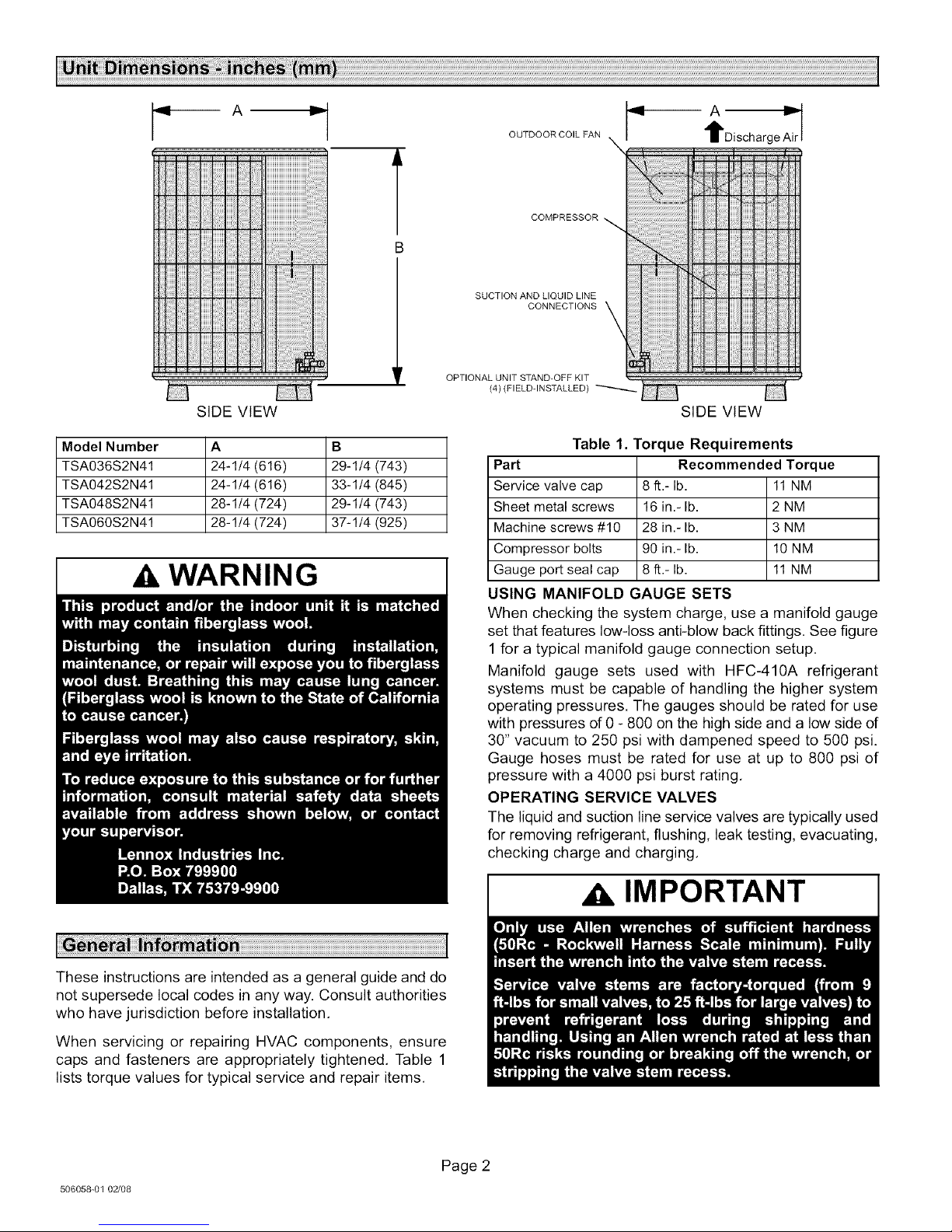
Model Number A B
TSA036S2N41 24-1/4 (616) 29-1/4 (743)
TSA042S2N41 24-1/4 (616) 33-1/4 (845)
TSA048S2N41 28-1/4 (724) 29-1/4 (743)
TSA060S2N41 28-1/4 (724) 37-1/4 (925)
WARNING
Table 1. Torque Requirements
Part Recommended Torque
Service valve cap 8 ft.- lb. 11 NM
Sheet metal screws 16 in.- lb. 2 NM
Machine screws #10 28 in.- lb. 3 NM
Compressor bolts 90 in.- lb. 10 NM
I
Gauge port seal cap 8 ft.- lb. 11 NM
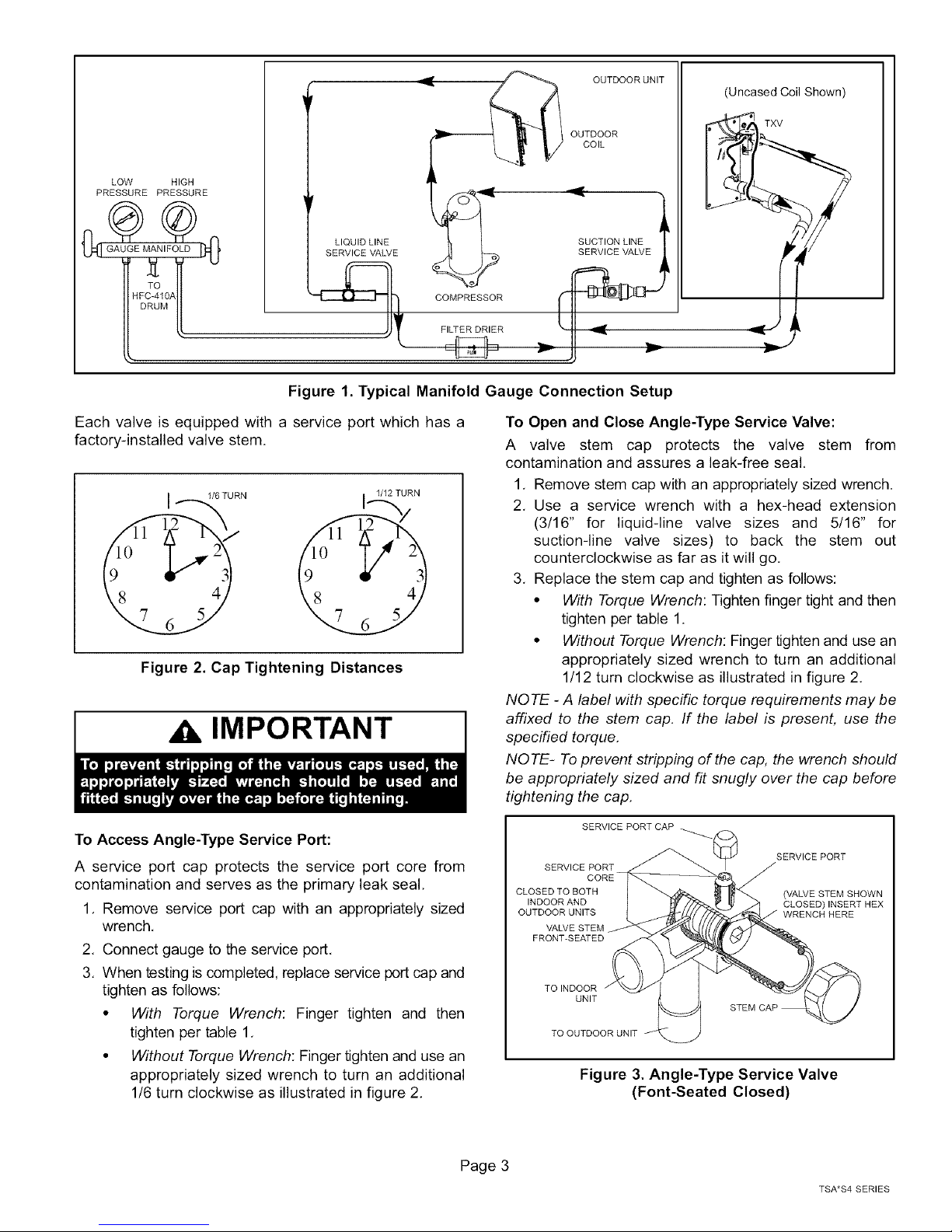
USING MANIFOLD GAUGE SETS
When checking the system charge, use a manifold gauge
set that features low-loss anti-blow back fittings. See figure
1 for a typical manifold gauge connection setup,
Manifold gauge sets used with HFC-410A refrigerant
systems must be capable of handling the higher system
operating pressures. The gauges should be rated for use
with pressures of 0 - 800 on the high side and a low side of
30" vacuum to 250 psi with dampened speed to 500 psi.
Gauge hoses must be rated for use at up to 800 psi of
pressure with a 4000 psi burst rating,
OPERATING SERVICE VALVES
The liquid and suction line service valves are typically used
for removing refrigerant, flushing, leak testing, evacuating,
checking charge and charging.
IMPORTANT
These instructions are intended as a general guide and do
not supersede local codes in any way. Consult authorities
who have jurisdiction before installation.
When servicing or repairing HVAC components, ensure
caps and fasteners are appropriately tightened. Table 1
lists torque values for typical service and repair items.
506058-01 02/08
Page 2
Page 3
OUTDOOR UNIT (Uncased Coil Shown)
LOW HIGH
PRESSURE PRESSURE
SERVICE VALVE
COMPRESSOR
FILTER DRIER
)MPRESSO_ _ I
Figure 1. Typical Manifold Gauge Connection Setup
Each valve is equipped with a service port which has a
factory-installed valve stem.
I/6 TURN
1/12 TURN
Figure 2. Cap Tightening Distances
,A IMPORTANT
OUTDOOR
COIL
SUCTION LINE
• TXV
To Open and Close Angle-Type Service Valve:
A valve stem cap protects the valve stem from
contamination and assures a leak-free seal,
1, Remove stem cap with an appropriately sized wrench.
2. Use a service wrench with a hex-head extension
(3/16" for liquidqine valve sizes and 5/16" for
suction-line valve sizes) to back the stem out
counterclockwise as far as it will go,
3. Replace the stem cap and tighten as follows:
• With Torque Wrench: Tighten finger tight and then
tighten per table 1.
• Without Torque Wrench: Finger tighten and use an
appropriately sized wrench to turn an additional
1/12 turn clockwise as illustrated in figure 2.
NOTE -A label with specific torque requirements may be
affixed to the stem cap, If the label is present, use the
specified torque,
NOTE- To prevent stripping of the cap, the wrench should
be appropriately sized and fit snugly over the cap before
tightening the cap,
To Access Angle-Type Service Port:
A service port cap protects the service port core from
contamination and serves as the primary leak seal,
1. Remove service port cap with an appropriately sized
wrench,
2, Connect gauge to the service port,
3. When testing is completed, replace service port cap and
tighten as follows:
• With Torque Wrench: Finger tighten and then
tighten per table 1,
• Without Torque Wrench: Finger tighten and use an
appropriately sized wrench to turn an additional
1/6 turn clockwise as illustrated in figure 2.
Page 3
SERVICE PORT
CLOSED TO BOTH
INDOOR AND
OUTDOOR UNITS
VALVE STEM
FRONT-SEATED
TOINDOOR
UNIT
TO OUTDOOR UNIT
Figure 3. Angle-Type Service Valve
SERVICE PORT CAP
(Font-Seated Closed)
STEM CAP
SERVICE PORT
CLOSED) INSERT HEX
WRENCH HERE
TSA*S4 SERIES
Page 4
SERVICEPORT
SERVICEPORT
OPENTOBOTH
INDOORAND
OUTDOORUNITS
TOINDOOR
UNIT
(VALVESTEMSHOWNOPEN)
INSERTHEXWRENCHHERE
STEMCAP
SERVICEPORT
• With Torque Wrench: Finger tighten and then
tighten per table 1.
• Without Torque Wrench: Finger tighten and use an
appropriately sized wrench to turn an additional
1/12 turn clockwise as illustrated in figure 2.
NOTE - A label with specific torque requirements may be
affixed to the stem cap. If the label is present, use the
specified torque.
TOOUTDOORUNIT
Figure 4. Angle-Type Service Valve
(Back-Seated Opened)
To Access Bali-Type Service Port:
A service port cap protects the service port core from
contamination and serves as the primary leak seal,
OPEN TO LINE SET WHEN VALVE IS CLOSED,
TO BOTH LINE SET AND UNIT WHEN VALVE IS
OPEN.
TO OPEN ROTATE STEM
COUNTERCLOCKWISE 90°. BALL(SHOWN
TO CLOSE ROTATE STEM
CLOCKWISE 90 °.
CORE
SERVlCEPORTCAP
TO INDOOR UNIT
CLOSED)
STEM CAP
VALVE
STEM
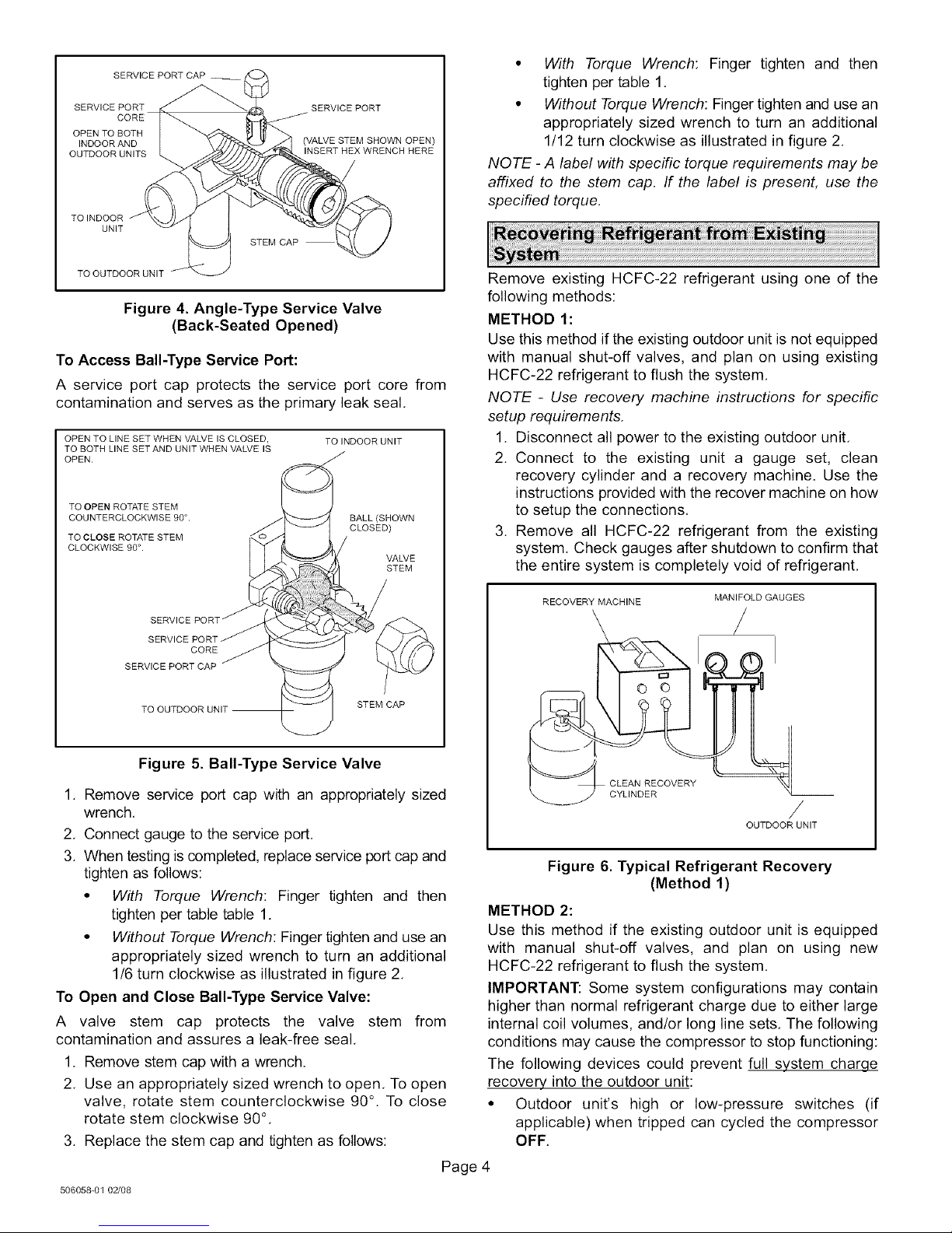
Remove existing HCFC-22 refrigerant using one of the
following methods:
METHOD 1:
Use this method if the existing outdoor unit is not equipped
with manual shut-off valves, and plan on using existing
HCFC-22 refrigerant to flush the system,
NOTE - Use recovery machine instructions for specific
setup requirements.
1. Disconnect all power to the existing outdoor unit,
2. Connect to the existing unit a gauge set, clean
recovery cylinder and a recovery machine. Use the
instructions provided with the recover machine on how
to setup the connections,
3. Remove all HCFC-22 refrigerant from the existing
system, Check gauges after shutdown to confirm that
the entire system is completely void of refrigerant,
RECOVERY MACHINE
MANIFOLD GAUGES
Figure 5. Bali-Type Service Valve
1. Remove service port cap with an appropriately sized
wrench,
2, Connect gauge to the service port.
3. When testing is completed, replace service port cap and
tighten as follows:
• With Torque Wrench: Finger tighten and then
tighten per table table 1.
• Without Torque Wrench: Finger tighten and use an
appropriately sized wrench to turn an additional
1/6 turn clockwise as illustrated in figure 2.
To Open and Close Bali-Type Service Valve:
A valve stem cap protects the valve stem from
contamination and assures a leak-free seal,
1. Remove stem cap with a wrench.
2. Use an appropriately sized wrench to open. To open
valve, rotate stem counterclockwise 90 °. To close
rotate stem clockwise 90°,
3. Replace the stem cap and tighten as follows:
506058-01 02/08
CLEAN RECOVERY
/
OUTDOOR UNIT
Figure 6. Typical Refrigerant Recovery
(Method 1)
METHOD 2:
Use this method if the existing outdoor unit is equipped
with manual shut-off valves, and plan on using new
HCFC-22 refrigerant to flush the system,
IMPORTANT: Some system configurations may contain
higher than normal refrigerant charge due to either large
internal coil volumes, and/or long line sets, The following
conditions may cause the compressor to stop functioning:
The following devices could prevent full system charqe
recovery into the outdoor unit:
• Outdoor unit's high or low-pressure switches (if
applicable) when tripped can cycled the compressor
OFF,
Page 4
Page 5

• Compressor can stop pumping due to tripped internal
pressure relief valve.
• Compressor has internal vacuum protection that is
designed to unload the scrolls (compressor stops
pumping) when the pressure ratio meets a certain
value or when the suction pressure is as high as 20
psig. (Compressor suction pressures should never be
allowed to go into a vacuum. Prolonged operation at
low suction pressures will result in overheating of the
scrolls and permanent damage to the scroll tips, drive
bearings and internal seals).
Once the compressor can not pump down to a lower
pressure due to one of the above system conditions, shut
off the suction valve. Turn OFF the main power to unit and
use a recovery machine to recover any refrigerant left in
the indoor coil and line set.
Perform the following task:
1. Start the existing HCFC-22 system in the cooling
mode and close the liquid line valve.
2. Pump as much of the existing HCFC-22 refrigerant
with the compressor back into the outdoor unit until
you have reached the limitations of the outdoor
system. Turn the outdoor unit main power OFF and
use a recovery machine to remove the remaining
refrigerant in the system.
NOTE - It may be necessary to bypass the low pressure
switches if equipped to ensure complete refrigerant
evacuation.
3. When the low side system pressures reach 0 psig,
close the suction line valve.
4. Check gauges after shutdown to confirm that the
valves are not allowing refrigerant to flow back into the
low side of the system.
* SEE NOTES BELOW THIS FIGURE FOR FURTHER DETAILS.
Figure 7. Installation Clearances
NOTES:
• Service clearance of 30 in. (762 mm) must be
maintained on one of the sides adjacent to the control
box.
• Clearance to one of the other three sides must be 36
in. (914 mm)
• Clearance to one of the remaining two sides may be
12 in. (305 mm) and the final side may be 6 in. (152
mm)
• 48 in. (1219 mm) clearance required on top of unit.
• A clearance of 24 in. (610 mm) must be maintained
between two units
POSITIONING CONSIDERATIONS
Consider the following when positioning the unit:
CAUTION
Perform the following task at the existing outdoor unit:
• Disconnect line set at the service valves.
• Disconnect electrical service at the disconnect switch.
• Remove old outdoor unit.
See Unit Dimensions on page 2 to sizing mounting slab,
platforms or supports. Refer to figure 7 for mandatory
installation clearance requirements.
• Some localities are adopting sound ordinances based
on the unit's sound level registered from the adjacent
property, not from the installation property. Install the
unit as far as possible from the property line.
• When possible, do not install the unit directly outside
a window. Glass has a very high level of sound
transmission. For proper placement of unit in relation
to a window see the provided illustration in figure 8.
Page 5
TSA*S4 SERIES
Page 6
INSTALLUNITAWAY_/_/_/
FROM_
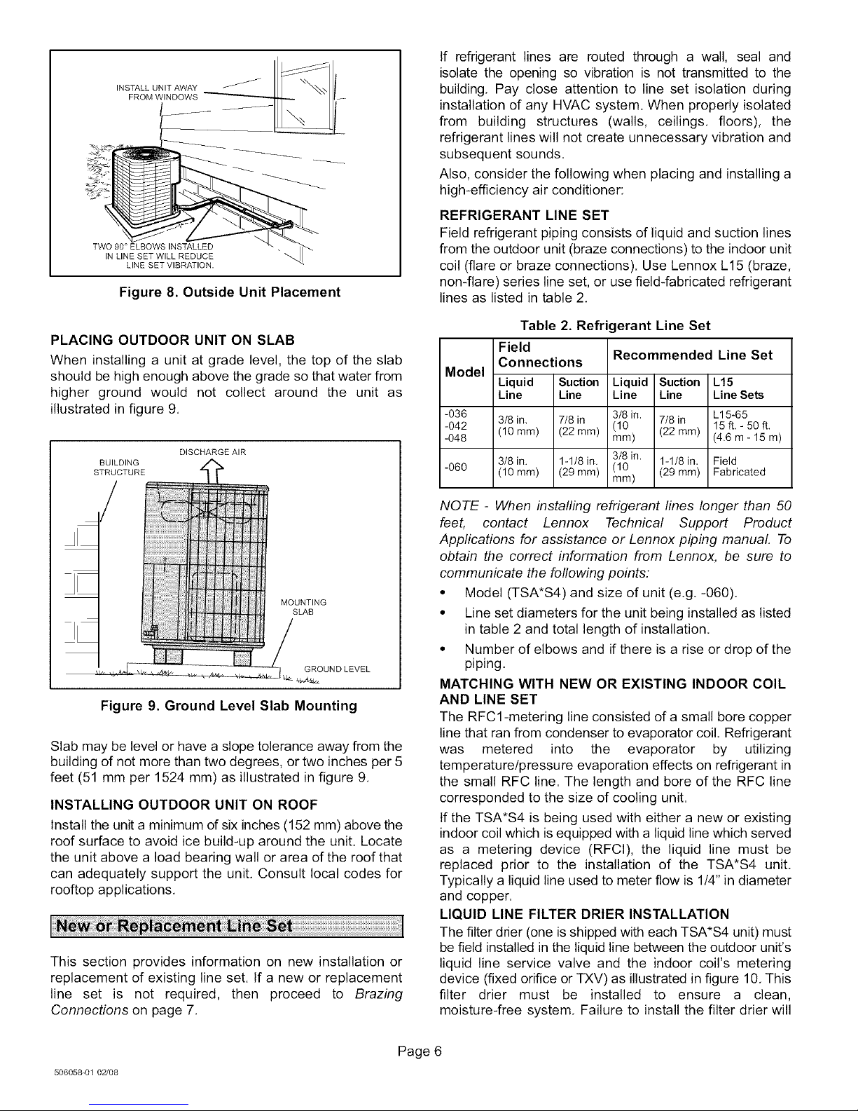
Figure 8. Outside Unit Placement
If refrigerant lines are routed through a wall, seal and
isolate the opening so vibration is not transmitted to the
building. Pay close attention to line set isolation during
installation of any HVAC system. When properly isolated
from building structures (walls, ceilings, floors), the
refrigerant lines will not create unnecessary vibration and
subsequent sounds.
Also, consider the following when placing and installing a
high-efficiency air conditioner:
REFRIGERANT LINE SET
Field refrigerant piping consists of liquid and suction lines
from the outdoor unit (braze connections) to the indoor unit
coil (flare or braze connections). Use Lennox L15 (braze,
non-flare) series line set, or use field-fabricated refrigerant
lines as listed in table 2.
PLACING OUTDOOR UNIT ON SLAB
When installing a unit at grade level, the top of the slab
should be high enough above the grade so that water from
higher ground would not collect around the unit as
illustrated in figure 9.
BUILDING
STRUCTURE
DISCHARGE AIR
MOUNTING
SLAB
GROUND LEVEL
Figure 9. Ground Level Slab Mounting
Slab may be level or have a slope tolerance away from the
building of not more than two degrees, or two inches per 5
feet (51 mm per 1524 mm) as illustrated in figure 9.
INSTALLING OUTDOOR UNIT ON ROOF
Install the unit a minimum of six inches (152 mm) above the
roof surface to avoid ice build-up around the unit. Locate
the unit above a load bearing wall or area of the roof that
can adequately support the unit, Consult local codes for
rooftop applications.
This section provides information on new installation or
replacement of existing line set. If a new or replacement
line set is not required, then proceed to Brazing
Connections on page 7.
Table 2. Refrigerant Line Set
Field
Model
-036
-042 (10 mm) (22 mm)
-048
-060 (10mm) (29mm)
Connections
Liquid Suction
Line Line
3/8 in, 7/8 in
3/8 in. 1-1/8 in,
Recommended Line Set
Liquid Suction L15
Line Line Line Sets
3/8 in. 7/8 in L15-65
(10 (22 ram) 15 ft. - 50 ft.
mm) (4.6 m - 15 m)
3/8 in. 1-1/8 in, Field
(10 (29 mm) Fabricated
mm)
NOTE - When installing refrigerant lines longer than 50
feet, contact Lennox Technical Support Product
Appfications for assistance or Lennox piping manual. To
obtain the correct information from Lennox, be sure to
communicate the following points:
• Model (TSA*S4) and size of unit (e.g, -060).
• Line set diameters for the unit being installed as listed
in table 2 and total length of installation,
• Number of elbows and if there is a rise or drop of the
piping,
MATCHING WITH NEW OR EXISTING INDOOR COIL
AND LINE SET
The RFCl-metering line consisted of a small bore copper
line that ran from condenser to evaporator coil. Refrigerant
was metered into the evaporator by utilizing
temperature/pressure evaporation effects on refrigerant in
the small RFC line. The length and bore of the RFC line
corresponded to the size of cooling unit.
If the TSA*S4 is being used with either a new or existing
indoor coil which is equipped with a liquid line which served
as a metering device (RFCI), the liquid line must be
replaced prior to the installation of the TSA*S4 unit,
Typically a liquid line used to meter flow is 1/4" in diameter
and copper.
LIQUID LINE FILTER DRIER INSTALLATION
The filter drier (one is shipped with each TSA*S4 unit) must
be field installed in the liquid line between the outdoor unit's
liquid line service valve and the indoor coil's metering
device (fixed orifice or TXV) as illustrated in figure 10, This
filter drier must be installed to ensure a clean,
moisture-free system, Failure to install the filter drier will
506058_01 02/08
Page 6
Page 7

voidthewarranty.A replacementfilterdrieris available
fromLennox.SeeBrazing Connections on page 7 for
special procedures on brazing filter drier connections to
the liquid line,
BRAZE CONNECTION POINTS
LIQUID
LINE
TAPE OR
WIRE TIE
OUTDOOR
UNIT
LIQUID LINE
SERVICE VALVE
LINE
LIQUID LINE
FILTER DRIER
Figure 10. Typical Liquid Line Filter Drier
Installation
LINE SET ISOLATION
Line set for heat pump applications can not be installed
underground, For more information see the Lennox
Refrigerant Piping Design and Fabrication Guidelines, or
contact Lennox Technical Support Product Applications
for assistance,
This reference illustrates procedures, which ensure proper
refrigerant line set isolation:
• Installation of line set on horizontal runs is
illustrated in figure 11.
• Installation of line set on vertical runs is illustrated in
figure 12,
• Installation of a transition from horizontal to
vertical is illustrated in figure 13,
TO HANG LINE SET FROM JOIST OR
RAFTER, USE EITHER METAL STRAPPING WIRE TIE
MATERIAL OR ANCHORED HEAVY NYLON (AROUND
WIRE TIES. SUCTION LINE
STRAPPING MATERIAL ONLY)
(AROUND SUCTION
LINE ONLY)
8 FEET
IMPORTANT - REFRIGERANT LINES MUST NOT CONTACT WALL.
OUTSIDE WALL SUCTION LINE LINE
NOTE - SIMILAR INSTALLATION SLEEVE
PRACTICES SHOULD BE USED
IF LINE SET IS TO BE INSTALLED WIRE TIE
ON EXTERIOR OF OUTSIDE --
WALL.
WOOD BLOCK
WIRE TIE
STRAP
SUCTION LINE WRAPPED WITH
LIQUID LINE
IMPORTANT! REFRIGERANT
LINES MUST NOT CONTACT
................................_ CAULK
PVC PIPE FIBERGLASS INSULATION
STRUCTURE.
Figure 12. Refrigerant Line Set: Installing
Vertical Runs (New Construction Shown)
ANCHORED HEAVY NYLON
WIRE TIE OR AUTOMOTIVE \
MUFFLER-TYPE HANGER
WALL
STUD
MUFFLER-TYPE HANGER
AUTOMOTIVE
\
X STRAP LIQUID LINE
TO SUCTION LINE
LIQUID
METAL
SLEEVE
TAPE OR
WIRE TIE STRAP THE SUCTION LINE TO
ROOF RAFTER -- ,b
FLOOR JOIST OR __>
THE JOIST OR RAFTER AT 8 FEET
INTERVALS THEN STRAP THE
LIQUID LINE TO THE SUCTION
LINE.
Figure 11. Refrigerant Line Set: Installing
Horizontal Runs
LIQUID LINE
METAL SLEEVE
A
Figure 13. Refrigerant Line Set: Transition
from Vertical to Horizontal
SUCTION LINE - WRAPPED
IN ARMAFLEX
Use the following procedure to braze the line set to the new
outdoor unit. Figure 14 is provided as a general guide for
preparing to braze the line set to the outdoor unit,
Page 7
TSA*S4 SERIES
Page 8

1
CUT AND DEBUR
INDOOR UNIT
REMOVE CAP AND CORE FROM
BOTH LIQUID AND SUCTION
SERVICE PORTS
SERVICE PORT MUST BE
OPEN TO ALLOW EXIT
POINT FOR NITROGEN SERVICE
j SUCTION LINE _ /VALVE
OUTDOOR
UNIT
INSTALL CORE ONLY FOR
BOTH SERVICE PORTS AFTER
THEY HAVE COOLED.
,,Ibm
WARNING
WARNING
LIQUtD LINE SERVICE J
VALVE
Figure 14. Brazing Connections
the valve stem port connection on the suction service
I
valve, The TXV metering device at the indoor unit coil
will allow low pressure nitrogen to flow through the
system.)
NOTE - The fixed orifice or TXV metering device at the
indoor unit will allow low pressure nitrogen to flow through
the system,)
NOTE - Use silver alloy brazing rods with five or six percent
minimum silver alloy for copper-to-copper brazing or 45
percent silver alloy for copper-to-brass or copper-to-steel
brazing,
6. Braze the line to the liquid line service valve. Turn off
I
nitrogen flow.
RAP /_
SER
VALVE _
IMPORTANT
1. Cut ends of the refrigerant lines square (free from
nicks or dents). Debur the ends, The pipe must remain
round, do not pinch end of the line.
2. Remove service cap and core from both the suction
and liquid line service ports.
3. Connect gauge low pressure side to liquid line service
valve,
4. To protect components during brazing, wrap a wet
cloth around the liquid line service valve body and
copper tube stub and use another wet cloth
underneath the valve body to protect the base paint.
5. Flow regulated nitrogen (at 1 to 2 psig) through the
refrigeration gauge set into the valve stem port
connection on the liquid line service valve and out of
506058-01 02/08
7. After all connections have been brazed, disconnect
manifold gauge set the from service ports and remove
wrapping. Reinstall the service port core for both of the
outdoor unit's service valves.
Remove the existing HCFC-22 refrigerant flow control
orifice or thermal expansion valve from the indoor coil.
REPLACEMENT PARTS
If replacement parts are necessary for the indoor unit,
order kit 69J46, The kit includes:
• 10 -- Brass nuts for liquid line assemblies
• 20 -- Teflon rings
• 10 -- Liquid line orifice housings
• 10 -- Liquid line assemblies
Page 8
Page 9

5. Disconnect the liquid line from the TXV at the liquid line
assembly.
6. Disconnect the TXV from the liquid line orifice housing.
Take care not to twist or damage distributor tubes
during this process.
7. Remove and discard TXV and the two Teflon rings as
illustrated in figure 17.
Figure 15.69J46 Kit Components
TYPICAL FIXED ORIFICE REMOVAL PROCEDURE
DISTRIBUTOR TUBES
LIQUID LINE ORIFICE HOUSING
TEFLON RING REMOVE AND DISCARD
FIXED VALVE STEM ASSEMBLY
. . .. J
(IF PRESENT)
BRASS NUT
/
O -" / ....
VALVE STEM CAP (Uncased Coil Shown)
Figure 16. Typical Fixed Orifice Removal
1. On fully cased coils, remove the coil access and
plumbing panels.
2. Remove any shipping clamps holding the liquid line
and distributor assembly.
3. Using two wrenches, disconnect liquid line from liquid
line orifice housing. Take care not to twist or damage
distributor tubes during this process.
4. Remove and discard fixed orifice, valve stem
assembly if present and Teflon ring as illustrated in
figure 16.
TYPICAL TXV REMOVAL PROCEDURE
1. On fully cased coils, remove the coil access and
plumbing panels.
2. Remove any shipping clamps holding the liquid line
and distributor assembly.
3. Disconnect the equalizer line from the TXV equalizer
line fitting on the suction line.
4. Remove the suction line sensing bulb as illustrated in
figure 17.
TWO PIECE
PATCH PLATE
JNCASED COIL LIQUID LINE
ONLY) \ ORIFICE HOUSING
)ISTRIBUTOR
TUBES
MALE EQUALIZER LINE /
FITTING J SUCTION
SENSING BULB LINE
STUB END
TXV
SENSING
LINE
/
LIQUID
LINE
Figure 17. Typical TXV Removal
A IMPORTANT
A IMPORTANT
If the original system used:
• HCFC-22 refrigerant, then flush the system using the
procedure provided in this section.
• HFC-410A refrigerant, then proceed to Installing New
Refrigerant Metering Device.
(Uncased Coil Shown)
Page 9
TSA*S4 SERIES
Page 10

CONTAINSCLEANHCFC-22TO
[_/ INVERTEDHCFC-22CYLINDER
BEUSEDFORFLUSHING. GAUGE
MANIFOLD
LOW HIGH
PRESSUREPRESSURE
SUCTION
CLOSED
LIQUIDLINESERVICEVALVE
RECOVERY
CYLINDER
RECOVERYMACHINE
NOTE -The inverted HCFC-22 cylinder must contain at least the same
amount of refrigerant as was recovered from the existing system.
Figure 18. Typical Flushing Connection
CAUTION
5, Close the valve on the inverted HCFC-22 drum and
the gauge set valves. Pump the remaining refrigerant
out of the recovery machine and turn the machine off.
6, Use dry nitrogen to break the vacuum on the
refrigerant lines and indoor unit coil before removing
the recovery machine, gauges and refrigerant drum,
TSA*S4 units are to be used with a HFC-410A TXV
metering device only. This section provides instructions on
installing a TXV refrigerant metering device,
TSA*S4 ENGINEERING HANDBOOK
See the TSA*S4 Engineering Handbook for approved
indoor/outdoor match-ups, applicable TXV kit and
application information,
The following is the typical contents of a TXV kit:
1 -- TXV
2 -- Teflon rings
1 -- 1 1/4" wide copper mounting strap for sensing bulb
2 --#10 hex head bolts and nuts for securing sensing bulb
REQUIRED EQUIPMENT
Equipment required to flush the existing line set and indoor
unit coil:
• Two clean HCFC-22 recovery bottles,
• Oilless recovery machine with pump-down feature,
• Two gauge sets (one for HCFC-22; one for
HFC-410A),
PROCEDURE
1, Connect the following:
• HCFC-22 cylinder with clean refrigerant to the
suction service valve,
• HCFC-22 gauge set to the liquid line valve,
• Recovery machine with an empty recovery tank to
the gauge set,
2, Set the recovery machine for liquid recovery and start
the recovery machine. Open the gauge set valves to
allow the recovery machine to pull a vacuum on the
existing system line set and indoor unit coil.
3, Invert the cylinder of clean HCFC-22 and open its
valve to allow liquid refrigerant to flow into the system
through the suction line valve. Allow the refrigerant to
pass from the cylinder and through the line set and the
indoor unit coil before it enters the recovery machine.
4, After all of the liquid refrigerant has been recovered,
switch the recovery machine to suction recovery so
that all d the HCFC-22 suction is recovered. Allow the
recovery machine to pull a vacuum on the system,
O_TEFLON
RINGS (2) _ I_
STRAP (1)
Figure 19. TXV Kit Components
t/2 TURN
Figure 20. Tightening Distance
TYPICAL TXV INSTALLATION PROCEDURE
The TXV unit can be installed internal or external to the
indoor coil. In applications where an uncased coil is being
installed in a field-provided plenum, install the TXV in a
manner that will provide access for field servicing of the
TXV. Refer to Figure 21 for reference during installation of
TXV unit,
506058-01 02/08
Page 10
Page 11

TWOPIECE (UncasedCoilShown)
PATCH PLATE
tNCASED COIL
ONLY) LIQUID LINE
DISTRIBUTOR TXV
TUBES. -
MALE EQUALIZER LINE
FITTING (SEE FIGURE 23 SUCTION
FOR FURTHER DETAILS) LINE
SENSING BULB INSULATION IS
REQUIRED IF MOUNTED EXTERNAL
TO THE COIL CASING. SEE FIGURE 22
FOR BULB POSITIONING
HOUSING
..._ORIFICE STUB END
RING
SENSING I
LINE
--...j
LIQUID
LINE
ON LINES SMALLER THAN
SUCTION LINE
/
BULB
\
SUCTION LINE ON 7/8" AND LARGER LINES,
• . ON BOTTOM OF LINE.
7, <" , ixj• * ,_,_L_ °
._."....
7/8", MOUNT SENSING BULB
AT EITHER THE 3 OR 9
O'CLOCK POSITION.
POSITION. NEVER MOUNT
(BULB ../('BULB)
NOTTTEoMNoEVLEREM,O UNT ON
Figure 22. TXV Sensing Bulb Installation
6. Remove and discard either the flare seal cap or flare
nut with copper flare seal bonnet from the equalizer
line port on the suction line as illustrated in figure 23.
A IMPORTANT
Figure 21. Typical TXV Installation
1, Install one of the provided Teflon rings around the
stubbed end of the TXV and lightly lubricate the
connector threads and expose surface of the Teflon
ring with refrigerant oil.
2. Attach the stubbed end of the kit valve to the liquid line
orifice housing, Finger tighten and use an appropriately
sized wrench to turn an additional 1/2 turn clockwise
as illustrated in figure 20, or 20 ft-lb,
3. Place the remaining Teflon washer around the other
end of the TXV. Lightly lubricate connector threads
and expose surface of the Teflon ring with refrigerant
oil,
4. Attach the liquid line assembly to the TXV. Finger
tighten and use an appropriately sized wrench to turn
an additional 1/2 turn clockwise as illustrated in figure
20, or 20 ft-lb.
5. Attach the suction line sensing bulb in the proper
orientation as illustrated in figure 22 using the clamp
an screws provided.
NOTE - Insulating the sensing bulb once installed may be
required when the bulb location is external to the coil
casing.
NOTE - To prevent any possibility of water damage,
properly insulate all parts of the TXV assembly that may
sweat due to temperature differences between the valve
and its surrounding ambient temperatures.
FLARE SEAL --
CAP
I
OR --FLARE SEAL
I
I MALE BRASS EQUALIZER
_ LINE FITTING
IFLARENUT
X COPPER
BONNET
J
SUCTION LINE
Figure 23. Copper Flare Seal Bonnet Removal
7, Connect the equalizer line from the TXV to the
equalizer suction port on the suction line. Finger
tighten the flare nut plus 1/8 turn (7 ft-lbs) as illustrated
in figure 20,
IMPORTANT
Page 11
TSA*S4 SERIES
Page 12

WARNING
WARNING I
After the line set has been connected to both the indoor
and outdoor units, check the line set connections at both
the indoor and outdoor units unit for leaks. Use the
following procedure to test for leaks:
1. Connect an HFC-410A manifold gauge set high
pressure hose to the suction valve service port.
NOTE - Normally, the high pressure hose is connected to
the fiquid line port; however, connecting it to the suction
port better protects the manifold gauge set from high
pressure damage,
2. With both manifold valves closed, connect the cylinder
of HFC-410A refrigerant to the center port of the
manifold gauge set. Open the valve on the HFC-410A
cylinder (suction only).
3. Open the high pressure side of the manifold to allow
HFC-410A into the line set and indoor unit,
4. Weigh in a trace amount of HFC-410A , [A trace
amount is a maximum of two ounces (57 g) refrigerant
or three pounds (31 kPa) pressure].
5. Close the valve on the HFC-410A cylinder and the
valve on the high pressure side of the manifold gauge
set.
6, Disconnect the HFC-410A cylinder,
7. Connect a cylinder of dry nitrogen with a pressure
regulating valve to the center port of the manifold
gauge set.
NOTE - Amounts of refrigerant will vary with line lengths.
8, Adjust dry nitrogen pressure to 150 psig (1034 kPa),
9. Open the valve on the high side of the manifold gauge
set in order to pressurize the line set and the indoor unit,
10. After a few minutes, open one of the service valve
ports and verify that the refrigerant added to the
system earlier is measurable with a leak detector.
11. Check all joints for leaks.
506058-01 02/08
I
Page 12
12. Purge dry nitrogen and HFC-410A mixture.
13. Correct any leaks and recheck.
14. After leak testing disconnect gauges from service
ports.
WARNING
IMPORTANT
Evacuating the system of non-condensables is critical for
proper operation of the unit. Non-condensables are
defined as any gas that will not condense under
temperatures and pressures present during operation of
an air conditioning system. Non-condensables and water
suction combine with refrigerant to produce substances
that corrode copper piping and compressor parts,
1. Connect manifold gauge set to the service valve ports
as follows:
• low pressure gauge to suction line service valve
• high pressure gauge to liquid line service valve
2. Connect micron gauge,
3. Connect the vacuum pump (with vacuum gauge) to
the center port of the manifold gauge set,
4. Open both manifold valves and start the vacuum
pump.
5. Evacuate the line set and indoor unit to an absolute
pressure of 23,000 microns (29.01 inches of
mercury).
NOTE - During the early stages of evacuation, it is
desirable to close the manifold gauge valve at least once to
determine if there is a rapid rise in sure indicates a
relatively large leak. If this occurs, repeat the leak testing
procedure.
NOTE - The term absolute pressure means the total
actual pressure within a given volume or system, above
the absolute zero of pressure, Absolute pressure in a
vacuum is equal to atmospheric pressure minus vacuum
pressure.
6. When the absolute pressure reaches 23,000 microns
(29.01 inches of mercury), close the manifold gauge
valves, turn off the vacuum pump and disconnect the
manifold gauge center port hose from vacuum pump.
Attach the manifold center port hose to a dry nitrogen
cylinder with pressure regulator set to 150 psig (1034
kPa) and purge the hose. Open the manifold gauge
valves to break the vacuum in the line set and indoor
unit. Close the manifold gauge valves.
Page 13

7. Shutoff the dry nitrogencylinderandremovethe
manifoldgaugehosefromthe cylinder.Openthe
manifoldgaugevalvestoreleasethedrynitrogenfrom
thelinesetandindoorunit,
8. Reconnectthemanifoldgaugetothevacuumpump,
turnthepumpon,andcontinuetoevacuatethelineset
andindoorunituntiltheabsolutepressuredoesnot
riseabove500microns(29.9inchesofmercury)within
a20-minuteperiodaftershuttingoffthevacuumpump
andclosingthemanifoldgaugevalves,
9.Whentheabsolutepressurerequirementabovehas
beenmet,disconnectthe manifoldhosefromthe
vacuumpumpandconnectittoanuprightcylinderof
HCFC-22refrigerant.Openthemanifoldgaugevalve
1to2psiginordertoreleasethevacuuminthelineset
andindoorunit,
10.Closemanifoldgauge valvesand shut off the
HCFC-22cylinderandremovethe manifoldgauge
set.
Ifthesystemisvoidofrefrigerant,cleanthesystemusing
theproceduredescribedbelow.
kWARNING
1. Usenitrogentopressurizethesystemandcheckfor
leaks.Repairallleaks.
2. Evacuatethe systemto removeas muchof the
moistureaspossible,
3. Usenitrogentobreakthevacuumandinstalla new
filterdrierinthesystem.
4. Evacuatethe system again. Then, weigh the
appropriateamountofHCFC-22refrigerantaslisted
onunitnameplateintothesystem,
5. Monitorthe systemto determinethe amountof
moistureremainingintheoil.Itmaybenecessaryto
replacethefilterdrierseveraltimesto achievethe
requireddrynesslevel.If systemdrynessis not
verified,thecompressorwill fail in thefuture.
Refertotheindoorunitinstallationinstructionforadditional
wiringapplicationdiagramsandrefertounitnameplatefor
minimumcircuitampacityand maximumovercurrent
protectionsize.Figures26and25illustratetypicaloutdoor
unitwiringdiagramsfortheTSA*S4seriesheatpumps,
• IntheU.S,A.,wiringmustconformwithcurrentlocal
codesandthecurrentNationalElectricCode(NEC).
• InCanada,wiringmustconformwithcurrentlocalcodes
andthecurrentCanadianElectricalCode(CEC).
GROUND
1 FIELD WIRING
HIGH VOLTAGE
1 FIELD WIRING
FIELD WIRING
L3
L2 L1
Figure 24. Separating High/Low Voltage
Field Wiring (Typical Field Wiring)
WIRING CONNECTIONS
1, Install line voltage power supply to unit from a properly
sized disconnect switch. Any excess high voltage field
wiring should be trimmed or secured away from the
low voltage field wiring.
2, Ground unit at unit disconnect switch or to an earth
ground.
3, Connect conduit to the unit using provided conduit
bushing.
4, Install room thermostat (ordered separately) on an
inside wall approximately in the center of the
conditioned area and five feet (1,5 m) from the floor.
It should not be installed on an outside wall or where
it can be affected by sunlight, drafts or vibrations.
NO TE - For proper voltages, select thermostat wire gauge
per the following table:
Page13
TSA*S4 SERIES
Page 14

B4
CI
OUTgOOR r_fl
Typical Field Wiring Diagram (Y and G Voltages)
RED
PURPLE
_LAC_
CAPACITOR _(
A_
J C_NTROL _
TO 24 VAC POWER
SOLK*CE
e0VA _N_.U_
NEC CLASS 2
---Ji
_1 C_ESS_IR
HR!
CR_£ HEATER
I I
I I
1 'I
' 1
l ) "_-_GRDUNII ll
I
"
A s_Tc. v
575160/3 K]-I
LI RED ]_1 S4
L_' _ YE_LDV _ S87
_Pa*AE]_T ]BLACK
- _l TRAN_FOR_ PDV_R gOURC£
A
FOR tJ_ WITH CDPP_ CONDUCTORS ONLy,
REFER TO L_IT R_TIN_ PLATE FgR _N]NLIM
C_RCtJIT AHPACITY /_ _XIleJ_ OV_RCURRENT
PRTECT]_ $]]JE
•_ 3L_PE_ IS USE3) VHE_ TOC IS NOT USE])
]_,JECTR_CSHOC_NAZA_.CAN CAt_ _JURY
DR EATH_ V_T _ _O4JND[D IN A_
Typical Field Wiring Diagram (J Voltage)
PR£SS_R[
NATIONAL AND L_L [_S,
_ DPT]ge_L COe_Dt,IF3_S
/ LIE VOLT_E £_D INSTALLED
..... CL_S _ V_LT_ FI_L9 V]RfN6
D u t
575/eo/3 t
S_7 DR _4
_,_2C CLASS _
_A
I
L2 I
t
Note: The thermostat used may be electro-mechanical or electronic
COOLING:
1. Cooling demand initiates a 24VAC signal from Y1 in the thermostat.
2. 24VAC from indoor unit Y1 energizes contacts K1-1, K1-2 and K1-3.
3. K1-1, K1-2 and K1-3 N.O. close, energizing compressor B1 and outdoor fan motor B4.
END OF COOLING DEMAND:
4. Cooling demand is satisfied. Terminal Y1 is de-energized.
5. Compressor contacts K1-1, K1-2 and K1-3 are de-energized.
6. K1-1, K1-2 and K1-3 open and compressor B1 and outdoor fan motor B4 are de-energized and stop immediately.
Figure 25. Typical Wiring Diagram
Table 3. Wire Run Lengths NOTE - 24VAC, Class II circuit connections are made in
Wire run length AWG # Insulation type the low voltage junction box
Less than 100 feet (30 m) 18 Color-coded with a minimum NOTE - Units are approved for use only with copper
More than 100 feet (30 m) 16 temperature rating of 35°C. conductors.
5, Install low voltage wiring from outdoor to indoor unit
and from thermostat to indoor unit as illustrated in
figures 26 and 25.
NOTE - To facilitate conduit, a hole is in the bottom of the
control box. Connect conduit to the control box using a
proper conduit fitting.
6, Do not bundle any excess 24VAC control wire inside
control box. Run control wire through installed wire tie
and tighten wire tie to provided low voltage strain relief
and to maintain separation of field installed low and
high voltage circuits,
NOTE - See unit wiring diagram for power supply
connections. If indoor unit is not equipped with blower
relay. It must be field-provided and installed (P-8-3251 or
equivalent)
506058-01 02/08
Page 14
Page 15

THERMOSTAT
C
@
G COOLING
COMMON
POWER
HEAT
INDOOR
BLOWER
INDOOR UNIT
©1
@
@
-@
OUTDOOR
UNIT
I
I
Figure 26. Typical Field Low Voltage Wiring
A IMPORTANT
1. Rotate fan to check for binding.
2. Inspect all factory- and field-installed wiring for loose
connections.
3, After evacuation is complete, open the liquid line and
suction line service valves to release the refrigerant
charge (contained in outdoor unit) into the system.
Delta-T
24 24 24 23 23 22 22 22 20 19 18 17 16 15
78
23 23 23 22 22 21 21 20 19 18 17 16 15 14
76
22 22 22 21 21 20 19 19 18 17 16 15 14 13
80
74
21 21 21 20 19 19 18 17 16 16 15 14 13 12
20 20 19 18 17 17 16 1L_,_15 14 13 12 11 10
19 19 18 18 17 17 16 15 15 14 13 12 11 10
I Wet-bulb °F
57 58 59 60 61 62 63 64 65 66 67 68 69 70 I
DRY
BULB
INDOOR i WET
COIL BULB
6
Figure 27. Checking Indoor Airflow over Evaporator Coil using Delta-T Chart
4, Replace the stem caps and tighten as specified in
Operating Service Valves on page 2.
5. Check voltage supply at the disconnect switch. The
voltage must be within the range listed on the unit's
nameplate. If not, do not start the equipment until you
have consulted with the power company and the
voltage condition has been corrected.
6, Set the thermostat for a cooling demand. Turn on
power to the indoor indoor unit and close the outdoor
unit disconnect switch to start the unit.
7, Recheck voltage while the unit is running. Power must
be within range shown on the nameplate,
8. Check system for sufficient refrigerate by using the
procedures listed under Testing and Charging
System,
SETTING UP TO CHECK CHARGE
1, Close manifold gauge set valves. Connect the center
manifold hose to an upright cylinder of HCFC-22,
2, Connect the manifold gauge set to the unit's service
ports as illustrated in figure 1,
• low pressure gauge to suction service port
• high pressure gauge to liquid service port
INDOOR AIRFLOW CHECK
Check airflow using the Delta-T (DT) process using the
illustration in figure 27,
DETERMINING CHARGE METHOD
Use the illustration in figure 28 to determine the correct
charging method.
1. Determine the desired DT--Measure entering air temperature
using dry bulb (A) and wet bulb (B) DT is the intersecting value of A
and B in the table (see triangle),
2. Find temperature drop across coil--Measure the coil's dry bulb
entering and leaving air temperatures (A and C). Temperature Drop
Formula: (TDrop) = A minus C.
I
3. Determine if fan needs adjustment--If the difference between the
I
measured TDrop and the desired DT (TDrop-DT) is within +3°, no ad-
justment is needed. See examples: Assume DT = 15 and A temp. =
72°, these C temperatures would necessitate stated actions:
C° TDrop- DT = °F ACTION
53° 19 - 15 = 4 Increase the airflow
58° 14 - 15 = -1 (within +3° range) nochange
62° 10 - 15 = -5 Decrease the airflow
4. Adjust the fan speed--See indoor unit instructions to increase/de-
crease fan speed
Changing air flow affects all temperatures; recheck temperatures to
confirm that the temperature drop and DT are within +3o
Page15
TSA*S4 SERIES
Page 16

WHEN TO CHARGE?
• Warm weather best
• Can charge in colder weather
CHARGE METHOD? Determine by:
• Metering device type
• Outdoor ambient temperature
REQUIREMENTS:
• Sufficient heat load in structure
• Indoor temperature between 70-80°F (21-26°C)
• Manifold gauge set connected to unit
• Thermometers:
to measure outdoor ambient temperature
to measure liquid line temperature
to measure suction line temperature
Figure 28. Determining Charge Method
and
ABOVE
64°F and
BELOW
1. Check Liquid and suction line pressures
2. Compare unit pressures with Table 4,
Normal Operating Pressures.
3. Conduct leak check; evacuate as
previously outlined.
4. Weigh in the unit nameplate charge plus
any charge required for line set differences
over feet.
TXV
Refrigerant Charge per Line Set Length
Liquid Line Ounces per 5feet (g per 1.5 m)
Set Diameter adjust from 15 feet (4.6 m) line set*
3t8" (9.5 mm) 3 ounce per 5' (85 g per 1.5 m)
NOTE - *If line length is greater than 15 ft. (4.6 m), add this
amount. If line length is less than !5 ft. (4.6 m), subtract this
amount.
Figure 29. HCFC-22 Weigh In
This nameplate is for illustration purposes
only. Go to actual nameplate on outdoor
unit for charge information.
506058@1 02/08
Page 16
Page 17

65°F
and II v
_ ABOVE I ]
USEWEIGH-INMETHODI ..... II
Neigh-in or remove refrigeran
based upon line length J64o F and"',_L-'J_
• BELOW '"
BLOCK OUTDOOR COIL: [sometimes necessary with lower
temperatures] Use cardboard or plastic sheet to restrict the airflow
through the outdoor coil to achieve pressures from 325-375 psig
(2240-2585 kPa). Higher pressures are needed to check charge.
Block equal sections of air intake panels and move coverings
sideways until the liquid pressure is in the above noted ranges.
I If refrigerant is added I
or removed, verify l_ If value is MORE
charge using the I than shown, remove
Approach Method. I refrigerant,
SC ° (Subcooling) Values (F:+/-1.0 ° [C: +/-0.6°])
°F (°C) -036 -042 -048 -060
than shown, add
I If value is LESS
refrigerant.
Any 12 (6.7) 8(4.4) 10 (5.6) 7 (3.9)
*Temperature of a r enter ng outdoor co
1. Confirm proper airflow across coil using figure
27.
2. Compare unit pressures with Table 4, Normal
Opera ting Pressures.
3. Set thermostat to call for heat (must have a
cooling load between 70-80°F (21-26°C)
4. Connect gauge set
5. Measure outdoor ambient temperature
6. When heat demand is satisfied, set thermostat to
call for cooling
7. Allow temperatures and pressures to stabilize.
NOTE - If necessary, block outdoor coil to
maintain 325 - 375 psig.
8. Record liquid line temperature:
Jiii
LIQo=
9. Measure liquid line pressure and use the value to
determine saturation temperature (see table 5):
SATo=
10. Subtract to determine subcooling (SC°):
SAT° . LIQ o = SC o
11. Compare results with table below.
Figure 30. HCFC-22 Subcooling TXV Charge
I If refrigerant is added I
or removed, verify l_
charge using the I
Subcooling Method. I
than shown, add
I If value is LESS
refrigerant,
If value is MORE
than shown, remove
refrigerant.
1. Confirm proper airflow across coil using figure
27.
2. Compare unit pressures with Table 4, Normal
Operating Pressures.
3. Set thermostat to call for heat (must have a
cooling load between 70-80°F (21-26°C).
4. Connect gauge set,
5. When heat demand is satisfied, set thermostat
to call for cooling.
6. Allow temperatures and pressures to stabilize.
7. Record outdoor ambient temperature:
AMB o=
8. Record liquid line temperature:
LIQo=
9. Subtract to determine approach (APP°):
LIQo . AMB o =App o
10. Compare results with table below.
APP ° (Approach) Values(F:+/-1.0 ° [C: +/-0.6°])
°F (°C)* -036 -042 -048 -060
Any 11 (6.1) 10(5.6) 6(3.3) 9(5.0)
*Temperature of air entering outdoor coil
Figure 31. HCFC-22 Approach TXV Charge
Page17
TSA*S4 SERIES
Page 18

Table 4. HCFC-22 Normal Operating Pressures (Liquid +10 and Suction +5 psig)
A IMPORTANT
TSA*S4 -036
°F (°C)* Liquid / Suction
Expansion Valve (TXV)
65 (18)
70 (21)
75 (24)
80 (27)
85 (29)
90 (32)
95(35)
100 (38)
105 (41)
110 (43)
115 (45)
263 / 135
281 / 138
302 / 140
325 / 142
349 / 142
375 / 143
404 / 144
433 / 145
462 / 147
494 / 149
527 / 150
-042
Liquid / Suction
250 / 135
268 / 137
288 / 138
310/ 139
332 / 140
356 / 140
381 / 141
406 / 143
432 / 143
459 / 145
490 / 145
-048
Liquid / Suction
240 / 130
257 / 131
278 / 132
299 / 133
323 / 134
344 / 135
369 / 136
394 / 137
418 / 139
446 / 140
477 / 141
-060
Liquid / Suction
242 / 130
266 / 131
286 / 132
309 / 133
332 / 134
357 / 135
381 / 136
407 / 137
433 / 138
459 / 140
488 / 141
Table 5. HFC-410A Temperature (°F) - Pressure (Psig)
°F Psig °F Psig °F Psig °F Psig °F Psig °F Psig °F Psig °F Psig
32 100.8 48 137.1 63 178.5 79 231.6 94 290.8 110 365.0 125 445.9 141 545.6
33 102.9 49 139.6 64 181.6 80 235.3 95 295.1 111 370.0 126 451.8 142 552.3
34 105.0 50 142.2 65 184.3 81 239.0 96 299.4 112 375.1 127 457.6 143 559.1
35 107.1 51 144.8 66 187.7 82 242.7 97 303.8 113 380.2 128 463.5 144 565.9
36 109.2 52 147.4 67 190.9 83 246.5 98 308.2 114 385.4 129 469.5 145 572.8
37 111.4 53 150.1 68 194.1 84 250.3 99 312.7 115 390.7 130 475.6 146 579.8
38 113.6 54 152.8 69 197.3 85 254.1 100 317.2 116 396.0 131 481.6 147 586.8
39 115.8 55 155.5 70 200.6 86 258.0 101 321.8 117 401.3 132 487.8 148 593.8
40 118.0 56 158.2 71 203.9 87 262.0 102 326.4 118 406.7 133 494.0 149 601.0
41 120.3 57 161.0 72 207.2 88 266.0 103 331.0 119 412.2 134 500.2 150 608.1
42 122.6 58 163.9 73 210.6 89 270.0 104 335.7 120 417.7 135 506.5 151 615.4
43 125.0 59 166.7 74 214.0 90 274.1 105 340.5 121 423.2 136 512.9 152 622.7
44 127.3 60 169.6 75 217.4 91 278.2 106 345.3 122 428.8 137 519.3 153 630.1
45 129.7 61 172.6 76 220.9 92 282.3 107 350.1 123 434.5 138 525.8 154 637.5
46 132.2 62 175.4 77 224.4 93 286.5 108 355.0 124 440.2 139 532.4 155 645.0
47 134.6 78 228.0 109 360.0 140 539.0
INSTALLING SERVICE VALVE CAPS
Disconnect gauge set and re-install both the liquid and
suction service valve caps,
The outdoor unit and indoor blower cycle on demand from
the room thermostat. When the thermostat blower switch
is in the ON position, the indoor blower operates
OUTDOOR UNIT
SERVICE VALVES _ /
INSTALL CAPS
continuously.
HIGH PRESSURE SWITCH
TSA*S4 units are equipped with a high-pressure switch
that is located in the liquid line of the compressor. The
switch (SPST, manual reset, normally closed) removes
power from the compressor when discharge pressure
Figure 32. Installing Service Valve Caps
rises above factory setting at 590 + 10 psi.
506058-01 02/08
Page 18
Page 19

Maintenanceandservicemustbeperformedbyaqualified
installeror serviceagency,At the beginningof each
coolingseason,thesystemshouldbecheckedasfollows:
,WARNING
OUTDOOR UNIT
1. Clean and inspect outdoor coil (may be flushed with a
water hose), Ensure power is off before cleaning,
2. Outdoor unit fan motor is pre-lubricated and sealed.
No further lubrication is needed,
3. Visually inspect all connecting lines, joints and coils for
evidence of oil leaks,
4. Check all wiring for loose connections,
5. Check for correct voltage at unit (unit operating).
6. Check amp draw on outdoor fan motor.
UNIT NAMEPLATE: ACTUAL:
7. Inspect drain holes in coil compartment base and
clean if necessary,
NOTE - If insufficient heating or cooling occurs, the unit
should be gauged and refrigerant charge should be
checked,
,&WARNING
,&,IMPORTANT
NOTE - A white residue may appear on the coil guards and
grilles on outdoor units. The residue is a non-toxic
byproduct of manufacturing the flexible coating. It can be
removed by wiping the coil guard with a cloth.
Maintenance and service must be performed by a qualified
installer or service agency. At the beginning of each
cooling season, the system should be checked as follows:
1. Make sure power is off before cleaning. Clean and
inspect outdoor coil. The coil may be flushed with a
water hose.
9 PINS USED ON -048
AND -060; 6 PINS ALL
OTHERS
INDOOR COIL
1. Clean coil if necessary.
2. Check connecting lines, joints and coil for evidence of
oil leaks.
3. Check condensate line and clean if necessary.
INDOOR UNIT
1, Clean or change filters.
2. Blower motors are prelubricated and permanently
sealed, No more lubrication is needed,
3. Adjust blower speed for cooling, Measure the pressure
drop over the coil to determine the correct blower CFM
Refer to the unit information service manual for pressure
drop tables and procedure.
4. Belt Drive Blowers - Check belt for wear and proper
tension,
5. Check all wiring for loose connections.
6. Check for correct voltage at unit, (blower operating)
7. Check amp draw on blower motor.
UNIT NAMEPLATE: ACTUAL:
PUSH PIN
MESH SCREEN /
Figure 33. Cleaning Debris from Mesh
2. The outdoor coil is protected by an inner mesh screen
and a wire cage (see figure 33). If debris has collected
between the mesh screen and the coil and cannot be
dislodged by spraying unpressurized water from
inside coil surface to the outside, the mesh may be
removed by first removing the top of the unit which will
allow for removal of the wire cage.
3. Then, using pliers to grip the head of the push pins, pull
straight out to extract the push pins along one side of
Page19
TSA*S4 SERIES
Page 20

the coil. If necessary, remove the push pins along the
back of the unit; it is usually unnecessary to fully
remove the inner mesh screen,
4, Drape the mesh screen back and wash the coil. When
all the debris has been removed from the coil, reinstall
the mesh screen by positioning it in its original position
and reinserting the push pin. No tool is required to
push the pin back into the same slot in the fins.
5, If the push pin is loose and tends not to stay in place,
brush the fins with a fin brush (22 fins/in). Line up the
push pin a couple fins to the right or left of the original
hole and re-insert the pin,
THERMOSTAT OPERATION
Thermostat operations vary from one thermostat to
another. The following provides general operation
procedures. Refer to the user's information manual
provided with your thermostat for specific operation
details,
• Temperature Setting Levers -- Set the lever or dial
to the desired temperature setpoints for both heating
and cooling. Avoid frequent temperature adjustment;
turning the unit off--then back on--before pressures
can equalize will put unusual stress on the unit's
compressor,
• Fan Switch -- In AUTO or INT (intermittent) mode,
the blower operates only when the thermostat calls for
heating or cooling. This mode is generally preferred
when humidity control is a priority. The ON or CONT
mode provides continuous indoor blower operation,
regardless of whether the compressor or furnace is
operating. This mode is required when constant air
circulation or filtering is desired,
• System Switch -- Set the system switch for heating,
cooling or auto operation, The auto mode allows the
system to automatically switch from heating mode to
cooling mode to maintain predetermined comfort
settings,
• Temperature Indicator -- The temperature indicator
displays the actual room temperature,
PROGRAMMABLE THERMOSTATS
Your Lennox system may be controlled by a
programmable thermostat. These thermostats provide the
added feature of programmable time-of-day setpoints for
both heating and cooling, Refer to the user's information
manual provided with your thermostat for operation
details,
PRESERVlCE CHECK
If your system fails to operate, check the following before
calling for service:
• Make sure all electrical disconnect switches are ON,
• Make sure the room thermostat temperature selector
AND the system switch are properly set.
• Replace any blown fuses, or reset circuit breakers,
• Make sure unit access panels are in place,
• Make sure air filter is clean.
• Locate and record unit model number before calling,
Refer to the Lennox TSA*S4 Engineering Handbook for
the latest available accessories for this unit. Below is a list
of accessories available at the time this instruction was
publish,
• Compressor start kit
• Loss of charge kit
• Sound cover
• Replacement liquid line drier
• Plastic feet kit
• Crankcase heater- 40W
Job Name
Job Location
Installer
Unit Model No,
Serial No.
Nameplate Voltage
Rated Load Ampacity
Maximum Fuse or Circuit Breaker
Electrical Connections Tight? _1
Indoor Blower RPM
Discharge Pressure __
S,P, Drop Over Indoor (Dry)
Suction Pressure
Refrigerant Lines: - Leak Checked? _1 Properly Insulated? _1 Outdoor Fan Checked? _1
Service Valves: --- Fully Opened? _1 Caps Tight? _1 Thermostat
Voltage With Compressor Operating Calibrated? _1 Properly Set? _1 Level? _1
506058-01 02/08
Compressor
Indoor Filter clean?
Job no. Date
City State
City State
Service Technician
Outdoor Fan
Supply Voltage (Unit Off)
Outdoor Coil Entering Air Temp.
Refrigerant Charge Checked?
Page 20
 Loading...