

Page 1
E N G I N E E R I N G D A T A
A I R C O N D I T I O N E R S
TS
T−CLASSt SPLIT SYSTEM UNITS
Standard Efficiency − R−410A − 60 HZ
Bulletin No. 210461
March 2008
Supersedes July 2007
MODEL NUMBER IDENTIFICATION
TSA Y1036 S 44 n
T = T−Classt Product Line
S = Split−System Air Conditioner
Brand/Family
Unit Type
Major Design Sequence
A = 1st Generation
B = 2nd Generation
Nominal Cooling Capacity − Tons
036 = 3 Tons
042 = 3.5 Tons
048 = 4 Tons
060 = 5 Tons
Cooling Efficiency
S = Standard Efficiency
SEER up to 14.0
3 to 5 Tons
Cooling Capacity − 33,400 to 62,500 Btuh
Vol ta ge
Y = 208/230V-3 phase-60hz
G = 460V-3 phase-60hz
J = 575V−3 phase−60hz
Minor Design Sequence
1 = 1st Revision
2 = 2nd Revision
3 = 3rd Revision
Coil Type
4 = Four−sided
Part Load Capability
N = No part load, single stage compressor
Refrigerant Type
4 = R−410A
Page 2
FEATURES
CONTENTS
ARI Rating Tables Pages 10−18. . . . . . . . . . . . . . . . . . . . . .
Dimensions Page 8. . . . . . . . . . . . . . . . . . . . . . . . . . . . . . . . .
Electrical Data Page 6. . . . . . . . . . . . . . . . . . . . . . . . . . . . . .
Features Pages 2−4. . . . . . . . . . . . . . . . . . . . . . . . . . . . . . . .
Guide Specifications Pages 19 − 23. . . . . . . . . . . . . . . . . . .
Indoor Coil / Air Handler Substitution Page 9. . . . . . . . . . .
Installation Clearances Page 7. . . . . . . . . . . . . . . . . . . . . . .
Model Number Identification Page 1. . . . . . . . . . . . . . . . . .
Outdoor Sound Data Page 7. . . . . . . . . . . . . . . . . . . . . . . . .
Specifications Page 6. . . . . . . . . . . . . . . . . . . . . . . . . . . . . . .
Warranty
Compressor − limited warranty for five years.
All other covered components − one year.
Refer to Lennox Equipment Limited Warranty certificate
included with unit for specific details.
Approvals
Certified in Accordance with the USE certification
program, which is based on ARI Standard 210/240−2005.
Sound rated in Lennox reverberant sound test room in
Accordance with test conditions included in ARI Standard
270-95.
Tested in the Lennox Research Laboratory environmental
test room.
Rated According to U.S. Department of Energy (DOE)
test procedures.
Units and components within bonded for grounding to
meet safety standards for servicing required by UL, NEC
and CEC.
Units are UL listed and CSA certified.
ISO 9001 Registered Manufacturing Quality System.
E
NERGY STAR® certified units are designed to use less
energy, help save money on utility bills, and help protect
the environment.
Applications
SEER up to 14.0.
3 through 5 ton.
Three−phase power supply.
Vertical air discharge allows concealment behind shrubs
at grade level or out of sight on a roof.
Matching add-on furnace indoor coils or air handlers
provide a wide range of cooling capacities and
applications. See ARI Ratings table.
See Indoor Coils and Air Handlers tab sections for unit
data.
Units shipped completely factory assembled, piped and
wired. Each unit test operated at the factory ensuring
proper operation.
Installer must set air conditioner, connect refrigerant lines
and make electrical connections to complete job.
For expanded ratings, see www.lennoxcommercial.com.
B
C
D
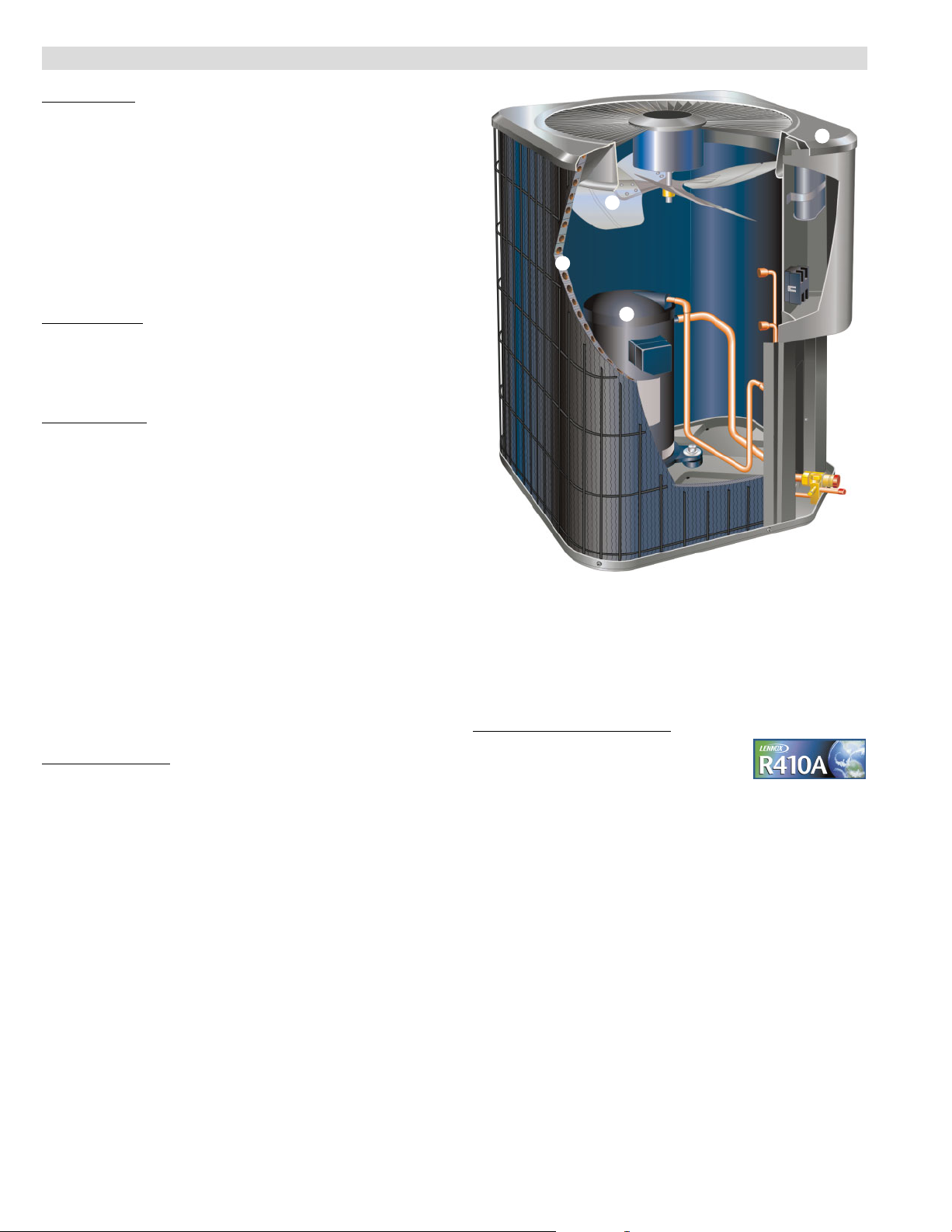
REFRIGERANT SYSTEM
Refrigerant
Non−chlorine, ozone friendly, R−410A.
Unit pre−charged with refrigerant. See Specification table.
Condenser Fan
B
Direct drive fan moves large air volumes uniformly
through entire condenser coil for high refrigerant cooling
capacity.
Vertical air discharge minimizes operating sounds and
eliminates damage to lawn and shrubs.
Fan motor has sleeve bearings and is inherently
protected.
Motor totally enclosed for maximum protection from
weather, dust and corrosion.
Rain shield on motor provides additional protection from
moisture.
Louvered steel top fan guard furnished as standard.
Fan service access accomplished by removal of top
panel.
E
F
TS − 3 to 5 Ton R−410A Air Conditioners / Page 2
Page 3
FEATURES
REFRIGERANT SYSTEM − CONTINUED
Copper Tube/Enhanced Fin Coil
C
Lennox designed and fabricated coil.
Ripple-edged aluminum fins.
Copper tube construction.
Lanced fins provide maximum exposure of fin surface to
air stream resulting in excellent heat transfer.
Fin collars grip tubing for maximum contact area.
Flared shoulder tubing connections/silver soldering
construction.
Coil is factory tested under high pressure to ensure
leakproof construction.
Entire coil is accessible for cleaning.
PVC coated steel wire coil guard furnished as standard.
High Pressure Switch Kit
Protects the system from high pressure conditions that
can be a result of fan failure or a blocked/dirty coil.
Manual reset.
OPTIONS
Expansion Valve Kits
Must be ordered extra and field installed on certain indoor
units. See ARI Ratings tables.
Chatleff−style fittings.
Loss of Charge Kit
Helps protect the compressor from damage due to low
refrigerant charge conditions.
SPST, normally−closed switch, automatic reset switch
mounted on suction line.
Refrigerant Line Kits
Refrigerant lines (suction & liquid) are shipped refrigeration
clean. Lines are cleaned, dried, pressurized and sealed at
factory.
Suction line fully insulated.
Lines are stubbed at both ends.
Not available for −060 models and must be field fabricated.
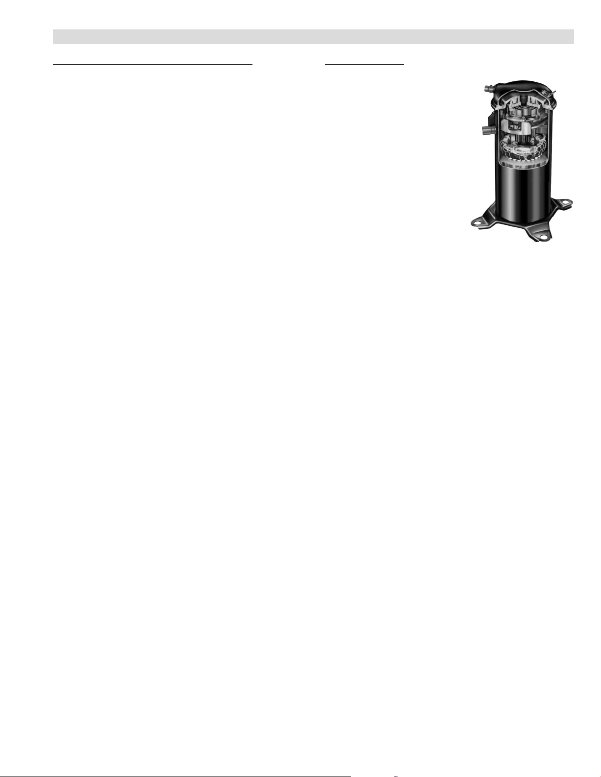
Compressor
Copeland Scrollt Compressor
D
Compressor features high
efficiency with uniform suction
flow, constant discharge flow
and high volumetric efficiency
and quiet operation.
Compressor consists of two
involute spiral scrolls matched
together to generate a series of
crescent shaped gas pockets
between them.
During compression, one scroll
remains stationary while the
other scroll orbits around it.
Gas is drawn into the outer
pocket, the pocket is sealed as
the scroll rotates.
As the spiral movement
continues, gas pockets are pushed to the center of the
scrolls. Volume between the pockets is simultaneously
reduced.
When pocket reaches the center, gas is now at high
pressure and is forced out of a port located in the center of
the fixed scrolls.
During compression, several pockets are compressed
simultaneously resulting in a smooth continuous
compression cycle.
Continuous flank contact, maintained by centrifugal force,
minimizes gas leakage and maximizes efficiency.
Scroll compressor is tolerant to the effects of slugging and
contaminants. If this occurs, scrolls separate, allowing
liquid or contaminants to to be worked toward the center
and discharged.
Low gas pulses during compression reduces operational
sound levels.
Compressor motor is internally protected from excessive
current and temperature.
Compressor is installed in the unit on resilient rubber
mounts for vibration free operation.
Compressor Crankcase Heater
Protects against refrigerant migration that can occur
during low ambient operation.
OPTIONS
Compressor Low Ambient Cut−Off
Non-adjustable switch (low ambient cut-out) prevents
compressor operation when outdoor temperature is
below 35°F.
Compressor Sound Cover
A reinforced vinyl compressor cover containing a 1−1/2
inch thick batt of fiberglass insulation.
All open edges are sealed with a one−inch wide hook and
loop fastening tape.
Compressor Timed−Off Control
Kit prevents compressor short−cycling and allows time for
suction and discharge pressure to equalize.
Permits compressor start−up in an unloaded condition.
Automatic reset with 5 minute delay between compressor
shut−off and start−up.
TS − 3 to 5 Ton R−410A Air Conditioners / Page 3
Page 4

FEATURES
Cabinet
E
Heavy gauge steel cabinet with five station metal wash
process.
Powder paint finish provides superior rust and corrosion
protection.
Painted base section.
Control box is conveniently located with all controls
factory wired.
Corner patch plate allows access to compressor
components.
Drainage holes are provided in base section for moisture
removal.
Refrigerant Line Connections, Electrical Inlets,
F
Service Valves
Sweat connection suction and liquid lines are located on
corner of unit cabinet.
Fully serviceable brass service valves prevent corrosion
and provide access to refrigerant system. Suction valve
can be fully shut off, while liquid valve may be front seated
to manage refrigerant charge while servicing system.
Refrigerant line connections and field wiring inlets are
located in one central area of cabinet for easy access. See
dimension drawing.
OPTIONS
Hail Guards
Constructed of louvered heavy gauge steel painted to
match cabinet.
Surrounds unit on all four sides to prevent damage to the coil.
Mounting Base
Provides permanent foundation for outdoor units.
High density polyethylene structural material is
lightweight, sturdy, sound absorbing and will withstand the
rigors of the sun, heat, cold, moisture, oil and refrigerant.
Will not mildew or rot.
Can be shipped singly or in packages of 6 to a carton.
Unit Stand-Off Kit
Black high density polyethylene feet are available to raise
unit off of mounting surface away from damaging
moisture.
Four feet are furnished per order number.
CONTROLS
OPTIONS
L Connection® Network
See L Connection Engineering Handbook Bulletin in
Controls section for details.
Low Ambient Control
Air conditioners operate satisfactorily down to 45°F
outdoor air temperature without any additional controls.
The Low Ambient Control Kit allows unit operation down
to 30°F.
Freezestat should be installed on compressors equipped
with a low ambient kit.
A compressor lock−out thermostat should be added to
terminate compressor operation below recommended
operation conditions.
Freezestat
Installs on or near the vapor line of the indoor coil or on the
suction line.
Senses suction line temperature and cycles the
compressor off when suction line temperature falls below
it’s setpoint.
Opens at 29°F and closes at 58°F.
Time Delay Relay Kit
Delays the indoor blower−off time during the cooling cycle.
See ARI Rating Tables for usage.
TS − 3 to 5 Ton R−410A Air Conditioners / Page 4
Page 5
OPTIONAL CONVENTIONAL TEMPERATURE CONTROL SYSTEMS − FIElD INSTALLED
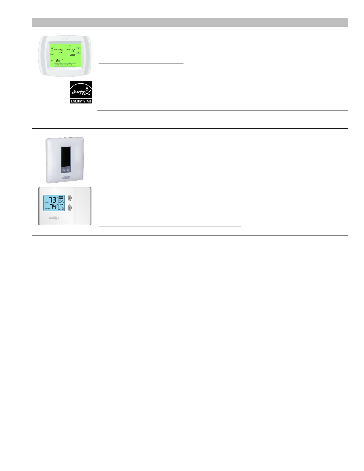
COMMERCIAL TOUCHSCREEN THERMOSTAT
Intuitive Touchscreen Interface − Two Stage Heating / Two Stage Cooling Conventional or
Heat Pump − Seven Day Programmable − Four Time Periods/Day − Economizer Output − Title 24
Compliant − E
NERGY STAR
Sensors For Touchscreen Thermostat
1
Remote non−adjustable wall mount 20k temperature sensor . . . . . . . . . . . . . . . . . . . . . . . . . . . . . . . C0SNZN01AE1−
1
Remote non−adjustable wall mount 10k averaging temperature sensor . . . . . . . . . . . . . . . . . . . . . C0SNZN73AE1−
1
Remote non−adjustable duct mount temperature sensor . . . . . . . . . . . . . . . . . . . . . . . . . . . . . . . . . . C0SNDC00AE1−
Outdoor temperature sensor . . . . . . . . . . . . . . . . . . . . . . . . . . . . . . . . . . . . . . . . . . . . . . . . . . . . . . . . . . . C0SNSR03AE1−
Accessories For Touchscreen Thermostat
Locking cover (clear) . . . . . . . . . . . . . . . . . . . . . . . . . . . . . . . . . . . . . . . . . . . . . . . . . . . . . . . . . . . . . . . . . . C0MISC15AE1−
1
Remote sensors for C0STAT02AE1L can be applied in the following combinations: (1)
C0SNZN01AE1−, (2) C0SNZN73AE1−, (2) C0SNZN01AE1− and (1) C0SNZN73AE1−, (4)
C0SNZN01AE1−, (3) C0SNZN01AE1− and (2) C0SNZN73AE1.
DIGITAL NON−PROGRAMMABLE THERMOSTATS
Intuitive Interface − Automatic Changeover − Simple Up and Down Temperature Control
Two−stage heating / cooling conventional systems . . . . . . . . . . . . . . . . . . . . . . . . . . . . . . . . . . . . . . . C0STAT10AE1L
Sensor For Digital Non−Programmable Thermostats Above
Remote wall mounted temperature sensor . . . . . . . . . . . . . . . . . . . . . . . . . . . . . . . . . . . . . . . . . . . . . . . C0SNZN00AE1−
Intuitive Interface − Automatic Changeover − Backlit Display − Simple Up and Down Temperature
Control
One−stage heating / cooling conventional systems . . . . . . . . . . . . . . . . . . . . . . . . . . . . . . . . . . . . . . . C0STAT12AE1L
Sensor For Digital Non−Programmable Thermostats Above
Outdoor temperature sensor . . . . . . . . . . . . . . . . . . . . . . . . . . . . . . . . . . . . . . . . . . . . . . . . . . . . . . . . . . . C0SNSR04AE1−
Accessories For Digital Non−Programmable Thermostats Above
Optional wall mounting plate . . . . . . . . . . . . . . . . . . . . . . . . . . . . . . . . . . . . . . . . . . . . . . . . . . . . . . . . . . . C0MISC17AE1−
®
Qualified − Backlit Display − Automatic Changeover
C0STAT02AE1L
TS − 3 to 5 Ton R−410A Air Conditioners / Page 5
Page 6
SPECIFICATIONS
General
Data
Connections
(sweat)
1
Refrigerant (R-410A) furnished 5 lbs. 9 oz. 8 lbs. 3 oz. 8 lbs. 4 oz. 10 lbs. 0 oz.
Outdoor
Coil area - sq. ft.
Outdoor
Fan
Shipping Data − lbs. 1 package 135 177 200 222
ELECTRICAL DATA
Line voltage data − 60 hz − 3ph 208/230V 460V 208/230V 460V 208/230V 460V 575V 208/230V 460V 575V
2
Maximum overcurrent protection (amps) 20 15 30 15 30 15 15 35 15 15
Compressor
Outdoor
Fan Motor
OPTIONAL ACcESSORIES − must be ordered extra
Compressor Low Ambient Cut−Off 45F08 S S S S
Compressor Sound Cover 69J03 S S S S
Compressor Time−Off Control 47J27 S S S S
Freezestat
Hail Guards
Loss of Charge Kit 84M23 S S S S
4
Low Ambient Kit (down to 30°F) 34M72 S S S S
Mounting Base
Refrigerant
Line Sets
Time Delay Relay Kit 58M81 S S S S
Unit Stand−Off Kit 94J45 S S S S
NOTE Extremes of operating range are plus 10% and minus 5% of line voltage.
1
Refrigerant charge sufficient for 15 ft. length of refrigerant lines.
2
HACR type circuit breaker or fuse.
3
Refer to National or Canadian Electrical Code manual to determine wire, fuse and disconnect size requirements.
4
Freezestat is recommended with Low Ambient Kit.
Model No. TSA036S4 TSA042S4 TSA048S4 TSA060S4
Nominal Tonnage 3
3.5 4 5
Liquid line o.d. − in. 3/8 3/8 3/8 3/8
Suction line o.d. − in. 7/8
Net face
Outer coil
Inner coil
13.22 15.11 16.32 21.00
− − −
7/8 7/8 1-1/8
14.40 15.71 20.25
Tube diameter − in. 5/16 5/16 5/16 5/16
Fins per inch − No. of rows 26 − 1 22 − 2 22 − 2 22 − 2
Diam. − in. − No. of blades 18 − 4 18 − 4 22 − 4 22 − 4
Motor hp 208/230V − 1/5
1/3 1/4 1/4
460V − 1/6
Cfm 2400 2930 3500 3830
Rpm 1090 1100 825 825
Watts 185 310 320 330
3
Minimum circuit ampacity 14.2 7.8 18.6 8.4 18.8 8.8 7.0 21.3 10.7 8.3
Rated load amps
Power factor
Locked rotor amps
Full load amps
Locked rotor amps
10.4 5.8 13.5 6.0 13.7 6.2 4.8 15.6 7.8 5.8
.85
73
.84 .83 .81 .90 .92 .88 .90 .91 .90
38 88 44 83.1 41 30.4 110 52 35.5
1.1 .55 1.7 1.0 1.7 1.0 1.0 1.7 1.0 1.0
1.9
1.1 4.1 2.2 3.1 2.3 2.3 3.1 2.3 2.3
3/8 in. tubing 93G35 S S S S
5/8 in. tubing 50A93 S S S S
92M88 S
92M89 S
92M92 S
92M90 S
69J06 S S
69J07 S S
L15−65−30, L15−65−40,
S S S
L15−65−50
Field Fabricate S
TS − 3 to 5 Ton R−410A Air Conditioners / Page 6
Page 7
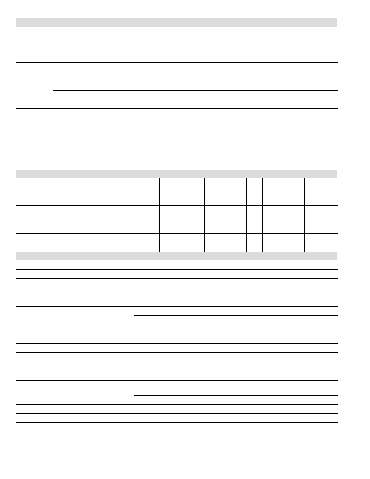
INSTALLATION CLEARANCES − INCHES (MM)
Model N
Numb
(dB)
NOTES:
See NOTES
Service clearance of 30 in. (762 mm) must be maintained on one of
the sides adjacent to the control box.
Clearance to one of the other three sides must be 36 in. (914 mm)
See
NOTES
See NOTES
See
NOTES
CONTROL
BOX
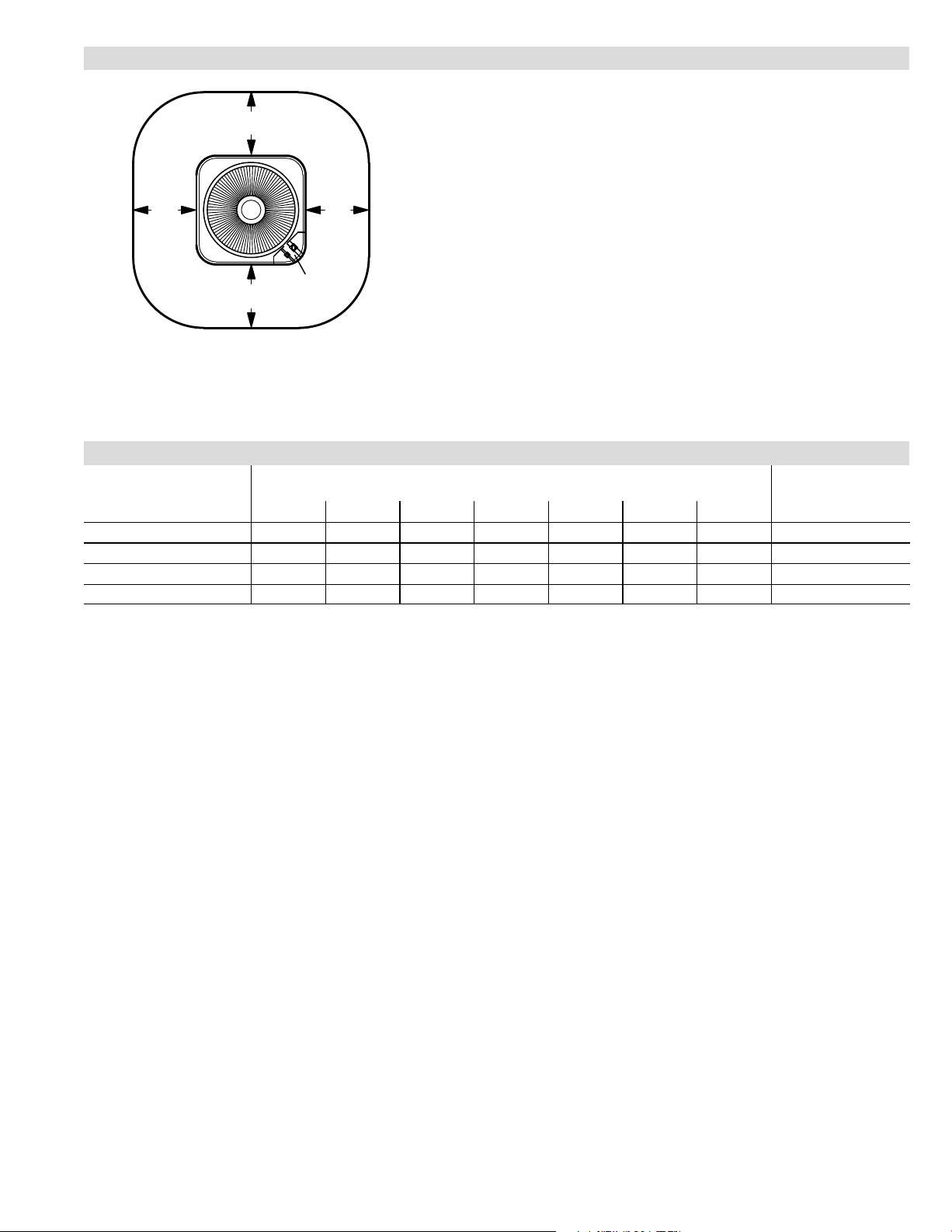
OUTDOOR SOUND DATA
1
Unit
o.
125
TSA036S4 70.5 67.5 69.5 72.5 69.5 63 59 76
TSA042S4 74 76.5 76.5 75.5 72 68 63.5 80
TSA048S4 73.5 76 76 76.5 72.5 69.5 64.5 80
TSA060S4 73.5 74.5 77 75 72 69 64.5 80
NOTE − the octave sound power data does not include tonal correction.
1
Tested according to ARI Standard 270 test conditions.
Octave Band Sound Power Levels dBA, re 10
250 500 1000 2000 4000 8000
Clearance to one of the remaining two sides may be 12 in. (305 mm)
and the final side may be 6 in. (152 mm).
A clearance of 24 in. (610 mm) must be maintained between two units.
48 in. (1219 mm) clearance required on top of unit.
−12
Center Frequency − HZ
Watts
1
Sound Rating
er
TS − 3 to 5 Ton R−410A Air Conditioners / Page 7
Page 8
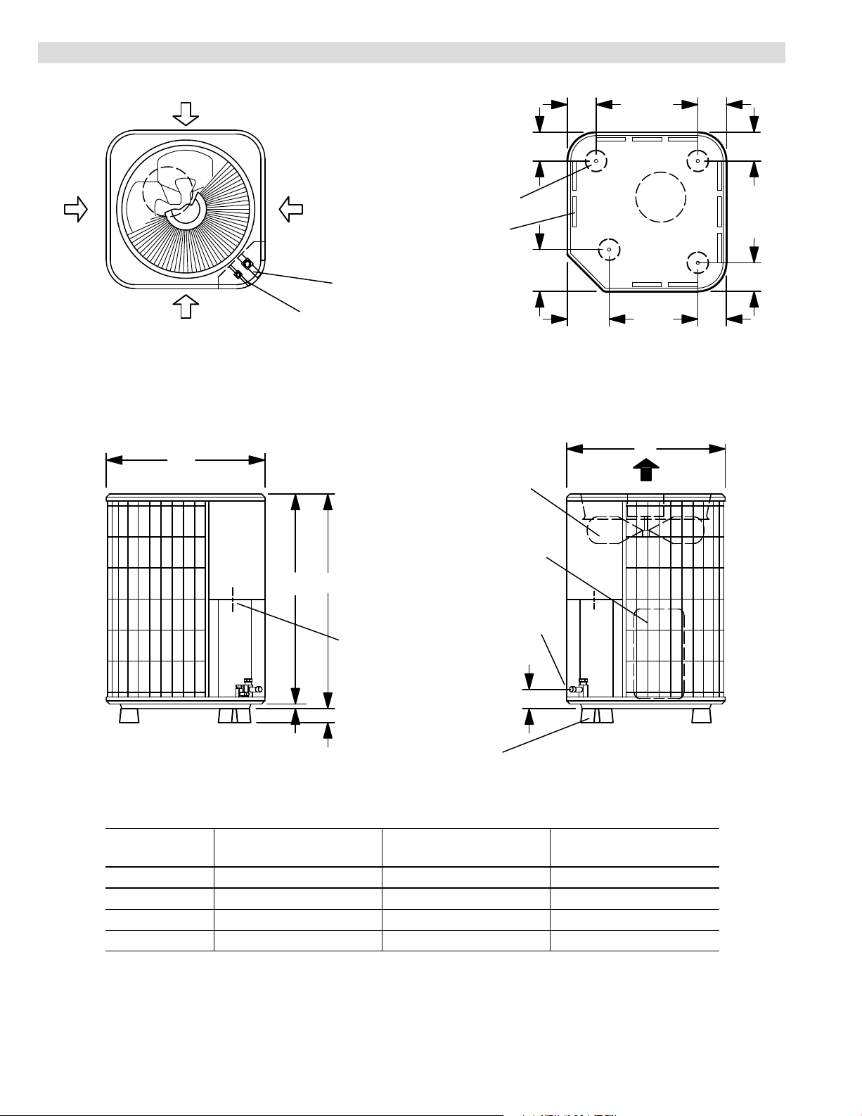
DIMENSIONS − INCHES (MM)
Model N
INLET
AIR
INLET AIR
INLET AIR
TOP VIEW
A
INLET
AIR
LIQUID LINE
CONNECTION
(Around perimeter of base)
SUCTION LINE
CONNECTION
OPTIONAL UNIT
STAND-OFF KIT (4)
(Field Installed)
COIL DRAIN OUTLETS
CONDENSER
COIL FAN
4-3/8
(111 )
6-3/8
(162)
4-3/8
(111 )
6-3/8
(162)
COMPRESSOR
4-3/8
(111 )
4-3/8
(111 )
TOP VIEW BASE SECTION
A
DISCHARGE AIR
4-3/8
(111)
4-3/8
(111)
COMPRESSOR
BC
SUCTION &
LIQUID LINE
CONNECTIONS
ELECTRICAL
INLETS
2-3/4 (70)
2 (51)
SIDE VIEW
TSA036S4
3/4
(19)
o.
in.
A B C
mm in. mm in. mm
24-1/4 616 29-1/4 743 28-1/2 724
OPTIONAL UNIT
STAND-OFF KIT (4)
(Field Installed)
SIDE VIEW
TSA042S4 24-1/4 616 33-1/4 845 32-1/2 826
TSA048S4 28-1/4 718 29−1/4 743 28−1/2 724
TSA060S4 28-1/4 718 37−1/4 946 36−1/4 921
TS − 3 to 5 Ton R−410A Air Conditioners / Page 8
Page 9

ARI RATINGS − INDOOR COIL / AIR HANDLER SUBSTITUTION
Substituting Coils in the ARI Tables
Most R−22 and R−410A indoor coils and air handlers are
the same except for the factory installed expansion
device. C33 coils can be used in place of the CX34 coils,
CB26UH−R, CB27UH, and CB30M air handlers can be
used in place of the CBX26UH, CBX27UH, and CBX32M,
respectively.
UP−FLOW COILS
R−410A R−22
CX34−18/24A−6F
CX34−18/24B−6F =
CX34−18/24C−6F =
CX34−19A−6F
CX34−25A−6F
CX34−25B−6F
CX34−30A−6F
CX34−30B−6F
CX34−30C−6F
CX34−31A−6F
CX34−31B−6F
CX34−36A−6F
CX34−36B−6F
CX34−36C−6F
CX34−38A−6F
CX34−38B−6F
CX34−42B−6F = C33−42B−2
CX34−43B−6F = C33−43B−2
CX34−43C−6F = C33−43C−2
no equivalent
CX34−44/48B−6F
CX34−44/48C−6F
CX34−49C−6F
CX34−50/60C−6F
CX34−60D−6F
CX34−62C−6F
CX34−62D−6F
=
C33−24A−2
C33−24B−2
C33−24C−2
=
C33−19A−2
=
C33−25A−2
=
C33−25B−2
=
C33−30A−2
=
C33−30B−2
=
C33−30C−2
=
C33−31A−2
=
C33−31B−2
=
C33−36A−2
=
C33−36B−2
=
C33−36C−2
=
C33−38A−2
=
C33−38B−2
C33−44C−2
=
C33−48B−2
=
C33−48C−2
=
C33−49C−2
=
C33−50/60C−2
=
C33−60D−2
=
C33−62C−2
=
C33−62D−2
The expansion device is based on the size of the outdoor
unit. The factory installed RFC or TXV on the
C33/CB26UH−R/CB27UH/CB30M must be replaced to
correspond to the outdoor unit. The correct TXV’s are:
1.5−3 ton air conditioners 37L51
3.5 ton air conditioners 39L72
4−5 ton air conditioners 91M02
Example:
A four−ton air conditioner is being installed. The ARI table
shows that CBX32M−048 is a matching air handler. A
CB30M−51 with a 91M02 TXV can be used in its place.
AIR HANDLERS
CBX26UH−018
CBX26UH−024 = CB26UH−024−R
CBX26UH−030 = CB26UH−030−R
CBX26UH−036
CBX26UH−042 = CB26UH−042−R
CBX26UH−048 = CB26UH−048
CBX26UH−060
CBX27UH−018/024 = CB27UH−018/024
CBX27UH−030 = CB27UH−030
CBX27UH−036
CBX27UH−042 = CB27UH−042
CBX27UH−048 = CB27UH−048
CBX27UH−060
CBX32M−018/024 = CB30M−21/26
CBX32M−030 = CB30M−31
CBX32M−036
CBX32M−042 = CB30M−46
CBX32M−048 = CB30M−51
CBX32M−060
R−410A R−22
= CB26UH−018−R
= CB26UH−036−R
= CB26UH−060−R
= CB27UH−036
= CB27UH−060
= CB30M−41
= CB30M−65
CBX32MV−all no equivalent
TS − 3 to 5 Ton R−410A Air Conditioners / Page 9
Page 10

ARI RATINGS
Total Unit
Devi
1
ARI Standard 210/240 Ratings
Cooling Capacity Efficiency
Btuh SEER EER
Total Unit
Watts
Indoor Unit Model No.
TSA036S4 3 TON
Up-Flow Indoor Coils Up−Flow Coils
33,800 13.00 10.90 3100
34,600 13.00 11.00 3145
34,800 13.00 11.00 3165
Up-Flow Indoor Coils + Furnace Up−Flow Coils + Furnace
34,400 13.50 11.50 2990 CX34−36C−6F
34,400 13.50 11.50 2990 CX34−36C−6F
34,800 14.00 11.60 3000 CX34−38B−6F
34,800 14.00 11.60 3000 CX34−38B−6F
35,000 13.50 11.60 3015 CX34−38A−6F
35,000 13.50 11.60 3015 CX34−38B−6F
35,200 14.00 11.60 3035 CX34−38B−6F
35,200 14.00 11.60 3035 CX34−43B−6F
35,200 14.00 11.60 3035 CX34−43B−6F
35,200 14.00 11.60 3035 CX34−43B−6F
35,600 14.00 11.60 3070 CX34−43B−6F
35,600 14.00 11.60 3070 CX34−50/60C−6F
35,600 14.00 11.60 3070 CX34−50/60C−6F
35,600 14.00 12.00 2965 CX34−43B−6F
35,600 14.00 12.00 2965 CX34−50/60C−6F
36,400 14.00 11.60 3140 CX34−50/60C−6F
36,400 14.00 11.60 3140 CX34−50/60C−6F
Down-Flow Indoor Coils Down−Flow Coils
34,000 13.00 11.00 3090
Down-Flow Indoor Coils + Furnace Down−Flow Coils + Furnace
33,400 13.50 11.00 3035 CR33−48B−F
33,400 13.50 11.00 3035 CR33−48B−F
33,600 13.00 11.00 3055 CR33−48B−F
33,800 14.00 11.60 2915 CR33−48B−F
34,200 13.50 11.00 3110 CR33−48B−F
34,800 13.50 11.50 3025 CR33−30/36C−F
34,800 13.50 11.50 3025 CR33−30/36C−F
Horizontal Indoor Coils Horizontal Coils
34,600 13.00 11.00 3145
34,800 13.00 11.00 3165
36,200 13.50 11.00 3290
1
Certified in accordance with USE certification program which is based on ARI Standard 210/240; 95_F outdoor air temperature, 80_F db/67_F wb entering evaporator air
with 25 ft. of connecting refrigerant lines.
2
Factory installed RFC or expansion valve on indoor unit MUST be replaced with expansion valve kit (ordered separately) shown.
3
Blower must be capable of time−off blower delay. Indoor Blower Off Delay Relay (58M81) is recommended for field installation.
4
Blower control must be set for a time−off blower delay.
5
Most popular indoor coil.
3, 5
CX34−38B−6F Factory TXV
3
CX34−50/60C−6F
3
CX34−43B−6F
4
G61MPV−36C−090 Factory TXV
4
G71MPP−36C−090 Factory TXV
4
G61MPV−36B−070 Factory TXV
4
G71MPP−36B−070 Factory TXV
4
G60UHV−36A−070 Factory TXV
4
G61MPV−36B−045 Factory TXV
4
G60UHV−36B−090 Factory TXV
4
G61MPV−36B−045
4
G61MPV−36B−070
4
G71MPP−36B−070
4
G61MPV−36B−071
4
G61MPV−60C−090
4
G71MPP−60C−090
4
G60UHV−36B−090
4
G60UHV−60C−110
4
G61MPV−60C−091
4
G61MPV−60C−111
3
CR33−48B−F
4
G61MPV−36B−070
4
G71MPP−36B−070
4
G61MPV−36B−045
4
G60DFV−36B−090
4
G61MPV−36B−071
4
G61MPV−36C−090
4
G71MPP−36C−090
3
CH33−44/48B−2F
3
CH33−48C−2F
3
CH33−43B−2F
Expansion
ce
2
37L51
2
37L51
2
37L51
2
37L51
2
37L51
2
37L51
2
37L51
2
37L51
2
37L51
2
37L51
2
37L51
2
37L51
2
37L51
2
37L51
2
37L51
2
37L51
2
37L51
2
37L51
2
37L51
2
37L51
2
37L51
2
37L51
2
37L51
TS − 3 to 5 Ton R−410A Air Conditioners / Page 10
Page 11

ARI RATINGS
Total Unit
Devi
1
ARI Standard 210/240 Ratings
Cooling Capacity Efficiency
Btuh SEER EER
Total Unit
Watts
Indoor Unit Model No.
TSA036S4 3 TON
Horizontal Indoor Coils + Furnace Horizontal Coils + Furnace
33,800 13.50 11.00 3075 CH23−51
33,800 13.50 11.00 3075 CH23−51
34,000 13.00 11.00 3090 CH23−51
34,200 14.00 11.60 2950 CH23−51
34,800 13.50 11.50 3025 CH33−44/48B−2F
34,800 13.50 11.50 3025 CH33−44/48B−2F
35,000 13.50 11.00 3180 CH33−44/48B−2F
35,200 13.50 11.50 3060 CH33−44/48B−2F
35,200 14.00 11.60 3035 CH33−44/48B−2F
35,600 14.00 11.60 3070 CH33−48C−2F
35,600 14.00 11.60 3070 CH33−48C−2F
35,600 14.00 11.60 3070 CH33−48C−2F
35,600 14.00 11.60 3070 CH33−48C−2F
Air Handlers Air Handlers
33,600 13.00 11.00 3055
3
CBX32M−030 (Multi−Position) Factory TXV
34,000 13.00 11.00 3090 CBX26UH−036 (Up−Flow / Horizontal) Factory TXV
34,200 12.80 10.70 3250
34,200 13.50 11.00 3110
34,200 13.50 11.00 3110
34,600 14.00 11.60 2985
35,200 13.50 11.50 3060
35,600 14.00 12.00 2965
36,200 14.00 12.00 3015
3
CB29M−46 (Multi−Position)
3
CBX32M−036 (Multi−Position) Factory TXV
3
CBX32M−042 (Multi−Position)
4
CBX32MV−036 (Multi−Position) Factory TXV
3
CBX32M−048 (Multi−Position)
4
CBX32MV−048 (Multi−Position)
3
CBX27UH−042 (Up−Flow / Horizontal)
4
G61MPV−36B−070
4
G71MPP−36B−070
4
G61MPV−36B−045
4
G60UHV−36B−090
4
G61MPV−36B−070
4
G71MPP−36B−070
4
G61MPV−36B−045
4
G61MPV−36B−071
4
G60UHV−36B−090
4
G61MPV−60C−090
4
G61MPV−60C−110
4
G71MPP−60C−090
4
G71MPP−60C−110
TSA042S4 3.5 TON
Up-Flow Indoor Coils Up−Flow Coils
40,000 13.00 10.80 3700
40,000 13.00 10.80 3700
40,500 13.00 10.90 3710
41,000 13.00 11.00 3715
Up-Flow Indoor Coils + Furnace Up−Flow Coils + Furnace
40,500 13.00 11.00 3690 CX34−38B−6F
40,500 13.00 11.00 3690 CX34−38B−6F
40,500 13.50 11.00 3555 CX34−38B−6F
40,500 14.00 11.50 3485 CX34−50/60C−6F
41,000 13.00 11.00 3680 CX34−43B−6F
41,000 13.00 11.00 3680 CX34−43B−6F
41,000 13.50 11.00 3590 CX34−50/60C−6F
41,000 13.50 11.00 3590 CX34−50/60C−6F
41,000 13.50 11.50 3575 CX34−49C−6F
41,000 13.50 11.50 3575 CX34−49C−6F
41,000 14.00 11.50 3475 CX34−49C−6F
41,000 14.00 11.50 3490 CX34−43C−6F
Up-Flow Indoor Coils + Furnace Continued on Next Page
1
Certified in accordance with USE certification program which is based on ARI Standard 210/240; 95_F outdoor air temperature, 80_F db/67_F wb entering evaporator air
with 25 ft. of connecting refrigerant lines.
2
Factory installed RFC or expansion valve on indoor unit MUST be replaced with expansion valve kit (ordered separately) shown.
3
Blower must be capable of time−off blower delay. Indoor Blower Off Delay Relay (58M81) is recommended for field installation.
4
Blower control must be set for a time−off blower delay.
5
Most popular indoor coil.
3
CX34−38A/B−6F
3
CX34−50/60C−6F
3, 5
CX34−43B/C−6F Factory TXV
3
CX34−49C−6F
4
G71MPP−36B−070
4
G61MPV−36B−070
4
G60UHV−36B−090
4
G60UHV−60C−090
4
G71MPP−36B−070 Factory TXV
4
G61MPV−36B−070 Factory TXV
4
G61MPV−60C−090
4
G71MPP−60C−090
4
G61MPV−60C−090
4
G71MPP−60C−090
4
G60UHV−60C−090
4
G60UHV−60C−090 Factory TXV
Expansion
ce
2
37L51
2
37L51
2
37L51
2
37L51
2
37L51
2
37L51
2
37L51
2
37L51
2
37L51
2
37L51
2
37L51
2
37L51
2
37L51
2
37L51
2
37L51
2
37L51
2
37L51
2
37L51
2
39L72
2
39L72
2
39L72
2
39L72
2
39L72
2
39L72
2
39L72
2
39L72
2
39L72
2
39L72
2
39L72
2
39L72
TS − 3 to 5 Ton R−410A Air Conditioners / Page 11
Page 12

ARI RATINGS
Total Unit
Devi
1
ARI Standard 210/240 Ratings
Cooling Capacity Efficiency
Btuh SEER EER
Total Unit
Watts
Indoor Unit Model No.
TSA042S4 3.5 TON
Up-Flow Indoor Coils + Furnace Continued from Previous Page
41,000 14.00 11.50 3510 CX34−49C−6F
41,000 14.00 11.50 3525 CX34−49C−6F
41,000 14.00 11.50 3525 CX34−49C−6F
41,000 14.00 11.50 3530 CX34−50/60C−6F
41,000 14.00 11.50 3535 CX34−43C−6F
41,000 14.00 11.50 3545 CX34−50/60C−6F
41,000 14.00 11.50 3545 CX34−50/60C−6F
41,000 14.00 11.50 3550 CX34−43B−6F
41,000 14.00 11.50 3550 CX34−43C−6F
41,000 14.00 11.50 3550 CX34−43C−6F
41,500 13.50 11.50 3595 CX34−43C−6F
41,500 13.50 11.50 3595 CX34−43C−6F
Down-Flow Indoor Coils Down−Flow Coils
40,000 13.00 10.80 3700
40,000 13.00 10.80 3700
3
CR33−50/60C−F
3
CR33−60D−F
Down-Flow Indoor Coils + Furnace Down−Flow Coils + Furnace
40,500 14.00 11.50 3475 CR33−50/60C−F
40,500 14.00 11.50 3520 CR33−50/60C−F
40,500 14.00 11.50 3520 CR33−50/60C−F
41,000 14.00 11.50 3495 CR33−60D−F
41,000 14.00 11.50 3495 CR33−60D−F
41,000 14.00 11.50 3495 CR33−60D−F
41,000 14.00 11.50 3515 CR33−50/60C−F
41,000 14.00 11.50 3565 CR33−50/60C−F
41,000 14.00 11.50 3565 CR33−50/60C−F
Horizontal Indoor Coils Horizontal Coils
39,500 13.00 10.70 3690
40,000 13.00 10.80 3700
41,000 13.00 11.00 3725
41,000 13.00 11.00 3725
41,000 13.00 11.00 3715
3
CH23−65
3
CH33−48C−2F
3
CH33−43B/C−2F
3
CH33−49C−2F
3
CH33−50/60C−2F
Horizontal Indoor Coils + Furnace Horizontal Coils + Furnace
40,500 13.50 11.00 3555 CH23−65
40,500 13.50 11.00 3595 CH23−65
40,500 13.50 11.00 3595 CH23−65
41,000 13.50 11.00 3725 CH33−43C−2F
41,000 13.50 11.00 3725 CH33−43C−2F
41,000 13.50 11.50 3565 CH33−43C−2F
41,000 13.50 11.50 3565 CH33−43C−2F
41,000 13.50 11.00 3725 CH33−43C−2F
Horizontal Indoor Coils + Furnace Continued on Next Page
1
Certified in accordance with USE certification program which is based on ARI Standard 210/240; 95_F outdoor air temperature, 80_F db/67_F wb entering evaporator air
with 25 ft. of connecting refrigerant lines.
2
Factory installed RFC or expansion valve on indoor unit MUST be replaced with expansion valve kit (ordered separately) shown.
3
Blower must be capable of time−off blower delay. Indoor Blower Off Delay Relay (58M81) is recommended for field installation.
4
Blower control must be set for a time−off blower delay.
4
G60UHV−60C−110
4
G71MPP−60C−110
4
G61MPV−60C−110
4
G60UHV−60C−110
4
G60UHV−60C−110 Factory TXV
4
G71MPP−60C−110
4
G61MPV−60C−110
4
G60UHV−36B−090 Factory TXV
4
G71MPP−60C−110 Factory TXV
4
G61MPV−60C−110 Factory TXV
4
G71MPP−60C−090 Factory TXV
4
G61MPV−60C−090 Factory TXV
4
G60DFV−60C−090
4
G71MPP−60C−110
4
G61MPV−60C−110
4
G60DFV−60D−135
4
G71MPP−60D−135
4
G61MPV−60D−135
4
G60DFV−60C−110
4
G71MPP−60C−090
4
G61MPV−60C−090
4
G60UHV−60C−090
4
G71MPP−60C−090
4
G61MPV−60C−090
4
G71MPP−36C−090
4
G61MPV−36C−090
4
G71MPP−60C−090
4
G61MPV−60C−090
4
G61MPV−60C−111
Expansion
ce
2
39L72
2
39L72
2
39L72
2
39L72
2
39L72
2
39L72
2
39L72
2
39L72
2
39L72
2
39L72
2
39L72
2
39L72
2
39L72
2
39L72
2
39L72
2
39L72
2
39L72
2
39L72
2
39L72
2
39L72
2
39L72
2
39L72
2
39L72
2
39L72
2
39L72
2
39L72
2
39L72
2
39L72
2
39L72
2
39L72
TS − 3 to 5 Ton R−410A Air Conditioners / Page 12
Page 13

ARI RATINGS
Total Unit
Devi
1
ARI Standard 210/240 Ratings
Cooling Capacity Efficiency
Btuh SEER EER
Total Unit
Watts
Indoor Unit Model No.
TSA042S4 3.5 TON
Horizontal Indoor Coils + Furnace Horizontal Coils + Furnace
41,000 13.50 11.00 3605 CH33−48C−2F
41,000 13.50 11.00 3605 CH33−48C−2F
41,000 13.50 11.50 3565 CH33−48C−2F
41,000 13.50 11.50 3565 CH33−48C−2F
41,000 14.00 11.50 3565 CH33−43C−2F
41,000 14.00 11.50 3565 CH33−43C−2F
41,000 14.00 11.50 3565 CH33−43C−2F
41,000 14.00 11.50 3565 CH33−43C−2F
41,500 13.00 10.90 3805 CH33−43B−2F
41,500 13.00 11.00 3775 CH33−43B−2F
41,500 13.00 11.00 3775 CH33−43B−2F
41,500 13.00 11.00 3775 CH33−43B−2F
41,500 13.50 11.50 3610 CH33−43B−2F
41,500 13.50 11.00 3775 CH33−43C−2F
41,500 13.50 11.00 3775 CH33−49C−2F
41,500 13.50 11.00 3775 CH33−49C−2F
41,500 13.50 11.50 3610 CH33−49C−2F
41,500 13.50 11.50 3610 CH33−49C−2F
41,500 13.50 11.00 3775 CH33−49C−2F
41,500 13.50 11.50 3575 CH33−50/60C−2F
41,500 13.50 11.50 3575 CH33−50/60C−2F
41,500 13.50 11.50 3615 CH33−50/60C−2F
41,500 13.50 11.50 3615 CH33−50/60C−2F
41,500 14.00 11.50 3610 CH33−49C−2F
41,500 14.00 11.50 3610 CH33−49C−2F
41,500 14.00 11.50 3610 CH33−49C−2F
41,500 14.00 11.50 3610 CH33−49C−2F
41,500 14.00 11.50 3610 CH33−49C−2F
41,500 14.00 11.50 3575 CH33−50/60C−2F
Air Handlers Air Handlers
38,500 12.50 10.50 3675
39,500 13.00 10.90 3605
39,500 13.00 10.90 3620
3
CB29M−46 (Multi−Position)
3
CBX32M−042 (Multi−Position)
3
CBX32M−036 (Multi−Position)
40,000 13.00 11.00 3635 CBX26UH−042 (Up−Flow/Horizontal) Factory TXV
41,000 13.00 11.00 3715
41,000 14.00 11.50 3565
41,500 14.00 11.50 3590
41,500 14.00 11.50 3610
1
Certified in accordance with USE certification program which is based on ARI Standard 210/240; 95_F outdoor air temperature, 80_F db/67_F wb entering evaporator air
with 25 ft. of connecting refrigerant lines.
2
Factory installed RFC or expansion valve on indoor unit MUST be replaced with expansion valve kit (ordered separately) shown.
3
Blower must be capable of time−off blower delay. Indoor Blower Off Delay Relay (58M81) is recommended for field installation.
4
Blower control must be set for a time−off blower delay.
3
CBX32M−048 (Multi−Position)
4
CBX27UH−048 (Up−Flow / Horizontal)
4
CBX32MV−048 (Multi−Position)
4
CBX27UH−042 (Up−Flow / Horizontal) Factory TXV
4
G71MPP−60C−090
4
G61MPV−60C−090
4
G71MPP−60C−110
4
G61MPV−60C−110
4
G60UHV−60C−090
4
G60UHV−60C−110
4
G71MPP−60C−110
4
G61MPV−60C−110
4
G61MPV−36B−045
4
G71MPP−36B−070
4
G61MPV−36B−070
4
G61MPV−36B−071
4
G60UHV−36B−090
4
G61MPV−60C−091
4
G71MPP−36C−090
4
G61MPV−36C−090
4
G71MPP−60C−090
4
G61MPV−60C−090
4
G61MPV−60C−091
4
G71MPP−60C−110
4
G61MPV−60C−110
4
G71MPP−60C−090
4
G61MPV−60C−090
4
G60UHV−60C−090
4
G60UHV−60C−110
4
G61MPV−60C−110
4
G71MPP−60C−110
4
G61MPV−60C−111
4
G60UHV−60C−090
Expansion
ce
2
39L72
2
39L72
2
39L72
2
39L72
2
39L72
2
39L72
2
39L72
2
39L72
2
39L72
2
39L72
2
39L72
2
39L72
2
39L72
2
39L72
2
39L72
2
39L72
2
39L72
2
39L72
2
39L72
2
39L72
2
39L72
2
39L72
2
39L72
2
39L72
2
39L72
2
39L72
2
39L72
2
39L72
2
39L72
2
39L72
2
39L72
2
39L72
2
39L72
2
39L72
2
39L72
TS − 3 to 5 Ton R−410A Air Conditioners / Page 13
Page 14

ARI RATINGS
Total Unit
Devi
1
ARI Standard 210/240 Ratings
Cooling Capacity Efficiency
Btuh SEER EER
Total Unit
Watts
Indoor Unit Model No.
tsa048s4 4 TON
Up-Flow Indoor Coils Up−Flow Coils
47,000 13.00 11.00 4255
47,000 13.00 11.00 4255
47,500 13.00 11.00 4260
48,000 13.50 11.00 4265
48,000 13.50 11.00 4270
48,500 13.50 11.00 4270
49,000 13.50 11.50 4270
Up-Flow Indoor Coils + Furnace Up−Flow Coils + Furnace
47,000 13.50 11.00 4155 CX34−50/60C−6F
47,000 13.50 11.00 4155 CX34−50/60C−6F
47,000 13.50 11.00 4165 CX34−50/60C−6F
47,000 13.50 11.00 4165 CX34−50/60C−6F
47,500 13.50 11.50 4115 CX34−50/60C−6F
47,500 13.50 11.50 4120 CX34−50/60C−6F
47,500 13.50 11.50 4145 CX34−43C−6F
47,500 13.50 11.50 4145 CX34−43C−6F
47,500 13.50 11.50 4155 CX34−43C−6F
47,500 13.50 11.50 4155 CX34−43C−6F
47,500 14.00 11.50 4105 CX34−43C−6F
48,000 14.00 11.50 4110 CX34−43C−6F
48,500 14.00 11.50 4080 CX34−60D−6F
48,500 14.00 11.50 4080 CX34−60D−6F
48,500 14.00 11.50 4110 CX34−49C−6F
48,500 14.00 11.50 4155 CX34−49C−6F
48,500 14.00 11.50 4155 CX34−49C−6F
48,500 14.00 11.50 4160 CX34−49C−6F
48,500 14.00 11.50 4160 CX34−49C−6F
48,500 14.00 12.00 4020 CX34−60D−6F
49,000 14.00 11.50 4120 CX34−49C−6F
49,000 14.00 11.50 4180 CX34−62C−6F
49,000 14.00 11.50 4180 CX34−62C−6F
49,000 14.00 12.00 4025 CX34−62D−6F
49,000 14.00 12.00 4085 CX34−62D−6F
49,000 14.00 12.00 4085 CX34−62D−6F
49,500 14.00 11.50 4135 CX34−62C−6F
49,500 14.00 11.50 4305 CX34−62C−6F
49,500 14.00 11.50 4305 CX34−62C−6F
49,500 14.00 12.00 4130 CX34−62C−6F
1
Certified in accordance with USE certification program which is based on ARI Standard 210/240; 95_F outdoor air temperature, 80_F db/67_F wb entering evaporator air
with 25 ft. of connecting refrigerant lines.
2
Factory installed RFC or expansion valve on indoor unit MUST be replaced with expansion valve kit (ordered separately) shown.
3
Blower must be capable of time−off blower delay. Indoor Blower Off Delay Relay (58M81) is recommended for field installation.
4
Blower control must be set for a time−off blower delay.
5
Most popular indoor coil.
3
CX34−38A/B−6F
3, 5
CX34−50/60C−6F Factory TXV
3
CX34−43B/C−6F
3
CX34−60D−6F Factory TXV
3
CX34−49C−6F Factory TXV
3
CX34−62D−6F Factory TXV
3
CX34−62C−6F Factory TXV
4
G61MPV−60C−110 Factory TXV
4
G71MPP−60C−110 Factory TXV
4
G61MPV−60C−090 Factory TXV
4
G71MPP−60C−090 Factory TXV
4
G60UHV−60C−110 Factory TXV
4
G60UHV−60C−090 Factory TXV
4
G71MPP−60C−110
4
G61MPV−60C−110
4
G71MPP−60C−090
4
G61MPV−60C−090
4
G60UHV−60C−110
4
G60UHV−60C−090
4
G61MPV−60D−135 Factory TXV
4
G71MPP−60D−135 Factory TXV
4
G60UHV−60C−110 Factory TXV
4
G61MPV−60C−110 Factory TXV
4
G71MPP−60C−110 Factory TXV
4
G61MPV−60C−090 Factory TXV
4
G71MPP−60C−090 Factory TXV
4
G60UHV−60D−135 Factory TXV
4
G60UHV−60C−090 Factory TXV
4
G61MPV−60C−090 Factory TXV
4
G71MPP−60C−090 Factory TXV
4
G60UHV−60D−135 Factory TXV
4
G61MPV−60D−135 Factory TXV
4
G71MPP−60D−135 Factory TXV
4
G60UHV−60C−090 Factory TXV
4
G61MPV−60C−110 Factory TXV
4
G71MPP−60C−110 Factory TXV
4
G60UHV−60C−110 Factory TXV
Expansion
ce
2
91M02
2
91M02
2
91M02
2
91M02
2
91M02
2
91M02
2
91M02
2
91M02
TS − 3 to 5 Ton R−410A Air Conditioners / Page 14
Page 15

Total Unit
Devi
ARI RATINGS
1
ARI Standard 210/240 Ratings
Cooling Capacity Efficiency
Btuh SEER EER
Total Unit
Watts
Indoor Unit Model No.
tsa048s4 4 TON
Down-Flow Indoor Coils + Furnace Down−Flow Coils + Furnace
46,500 13.50 11.00 4085 CR33−60D−F
46,500 13.50 11.00 4085 CR33−60D−F
46,500 13.50 11.00 4100 CR33−50/60C−F
46,500 13.50 11.00 4140 CR33−50/60C−F
46,500 13.50 11.00 4140 CR33−50/60C−F
46,500 13.50 11.00 4145 CR33−50/60C−F
46,500 13.50 11.00 4145 CR33−50/60C−F
47,000 13.50 11.00 4100 CR33−50/60C−F
47,000 13.50 11.50 4075 CR33−60D−F
Horizontal Indoor Coils Horizontal Coils
47,000 13.00 11.00 4260
47,000 13.00 11.00 4260
47,500 13.00 11.00 4320
47,500 13.00 11.00 4265
47,500 13.50 11.00 4265
48,000 13.50 11.00 4365
48,000 13.50 11.00 4265
48,000 13.50 11.00 4365
3
CH33−44/48B−2F
3
CH33−48C−2F
3
CH33−43C−2F
3
CH33−60D−2F
3
CH23−68
3
CH33−49C−2F
3
CH33−50/60C−2F
3
CH33−62D−2F
Horizontal Indoor Coils + Furnace Horizontal Coils + Furnace
47,500 13.50 11.00 4320 CH33−43C−2F
47,500 13.50 11.00 4320 CH33−43C−2F
47,500 13.50 11.00 4320 CH33−43C−2F
47,500 13.50 11.00 4320 CH33−43C−2F
47,500 13.50 11.00 4320 CH33−43C−2F
47,500 13.50 11.00 4320 CH33−43C−2F
47,500 13.50 11.00 4180 CH33−48C−2F
47,500 13.50 11.00 4180 CH33−48C−2F
47,500 13.50 11.00 4180 CH33−48C−2F
47,500 13.50 11.00 4180 CH33−48C−2F
47,500 13.50 11.50 4135 CH33−48C−2F
47,500 13.50 11.50 4140 CH33−48C−2F
48,000 13.50 11.50 4175 CH33−43C−2F
48,000 13.50 11.50 4185 CH33−50/60C−2F
48,000 13.50 11.50 4185 CH33−50/60C−2F
48,000 13.50 11.50 4185 CH33−50/60C−2F
48,000 13.50 11.50 4185 CH33−50/60C−2F
48,000 14.00 11.50 4175 CH33−43C−2F
48,000 14.00 11.50 4040 CH33−60D−2F
48,000 14.00 11.50 4040 CH23−68
48,000 14.00 11.50 4095 CH33−60D−2F
48,000 14.00 11.50 4095 CH33−60D−2F
48,000 14.00 11.50 4095 CH23−68
48,000 14.00 11.50 4095 CH23−68
Horizontal Indoor Coils + Furnace Continued on Next Page
1
Certified in accordance with USE certification program which is based on ARI Standard 210/240; 95_F outdoor air temperature, 80_F db/67_F wb entering evaporator air
with 25 ft. of connecting refrigerant lines.
2
Factory installed RFC or expansion valve on indoor unit MUST be replaced with expansion valve kit (ordered separately) shown.
3
Blower must be capable of time−off blower delay. Indoor Blower Off Delay Relay (58M81) is recommended for field installation.
4
Blower control must be set for a time−off blower delay.
4
G61MPV−60D−135
4
G71MPP−60D−135
4
G60DFV−60C−110
4
G71MPP−60C−110
4
G61MPV−60C−110
4
G71MPP−60C−090
4
G61MPV−60C−090
4
G60DFV−60C−090
4
G60DFV−60D−135
4
G71MPP−60C−090
4
G61MPV−60C−090
4
G61MPV−60C−091
4
G61MPV−60C−110
4
G71MPP−60C−110
4
G61MPV−60C−111
4
G61MPV−60C−090
4
G71MPP−60C−090
4
G61MPV−60C−110
4
G71MPP−60C−110
4
G60UHV−60C−110
4
G60UHV−60C−090
4
G60UHV−60C−110
4
G71MPP−60C−090
4
G61MPV−60C−090
4
G71MPP−60C−110
4
G61MPV−60C−110
4
G60UHV−60C−090
4
G60UHV−60D−135
4
G60UHV−60D−135
4
G71MPP−60D−135
4
G61MPV−60D−135
4
G71MPP−60D−135
4
G61MPV−60D−135
TS − 3 to 5 Ton R−410A Air Conditioners / Page 15
Expansion
ce
2
91M02
2
91M02
2
91M02
2
91M02
2
91M02
2
91M02
2
91M02
2
91M02
2
91M02
2
91M02
2
91M02
2
91M02
2
91M02
2
91M02
2
91M02
2
91M02
2
91M02
2
91M02
2
91M02
2
91M02
2
91M02
2
91M02
2
91M02
2
91M02
2
91M02
2
91M02
2
91M02
2
91M02
2
91M02
2
91M02
2
91M02
2
91M02
2
91M02
2
91M02
2
91M02
2
91M02
2
91M02
2
91M02
2
91M02
2
91M02
2
91M02
Page 16

ARI RATINGS
Total Unit
Devi
1
ARI Standard 210/240 Ratings
Cooling Capacity Efficiency
Btuh SEER EER
Total Unit
Watts
Indoor Unit Model No.
tsa048s4 4 TON
Horizontal Indoor Coils + Furnace (Continued) Horizontal Coils + Furnace
48,000 14.00 11.50 4140 CH33−50/60C−2F
48,500 13.50 11.00 4410 CH33−49C−2F
48,500 13.50 11.50 4215 CH33−62D−2F
48,500 14.00 11.50 4215 CH33−49C−2F
48,500 14.00 11.50 4215 CH33−49C−2F
48,500 14.00 11.50 4215 CH33−49C−2F
48,500 14.00 11.50 4215 CH33−49C−2F
48,500 14.00 11.50 4215 CH33−49C−2F
48,500 14.00 11.50 4215 CH33−49C−2F
48,500 14.00 11.50 4215 CH33−49C−2F
48,500 14.00 11.50 4140 CH33−50/60C−2F
48,500 14.00 11.50 4215 CH33−62D−2F
48,500 14.00 11.50 4215 CH33−62D−2F
48,500 14.00 11.50 4215 CH33−62D−2F
48,500 14.00 11.50 4215 CH33−62D−2F
48,500 14.00 11.50 4215 CH33−62D−2F
48,500 14.00 11.50 4215 CH33−62D−2F
48,500 14.00 11.50 4215 CH33−62D−2F
48,500 14.00 12.00 4045 CH33−62D−2F
48,500 14.00 11.50 4100 CH33−62D−2F
48,500 14.00 11.50 4100 CH33−62D−2F
Air Handlers Air Handlers
45,000 12.30 10.20 4385
47,500 13.50 11.00 4145
47,500 14.00 11.50 4130
47,500 14.00 11.50 4130
48,000 13.50 11.50 4145
48,500 13.50 11.50 4210
48,500 14.00 11.50 4150
3
CB29M−51 (Multi−Position)
3
CBX32M−048 (Multi−Position) Factory TXV
4
CBX27UH−048 (Up−Flow / Horizontal) Factory TXV
4
CBX27UH−060 (Up−Flow / Horizontal) Factory TXV
4
CBX32MV−048 (Multi−Position) Factory TXV
3
CBX32M−060 (Multi−Position) Factory TXV
4
CBX32MV−060 (Multi−Position) Factory TXV
48,500 14.00 11.50 4190 CBX26UH−048 (Up−Flow/Horizontal) Factory TXV
49,500 14.00 11.50 4195
3
CBX32M−042 (Multi−Position) Factory TXV
4
G60UHV−60C−110
4
G61MPV−60C−091
4
G61MPV−60C−091
4
G60UHV−60C−090
4
G60UHV−60C−110
4
G61MPV−60C−090
4
G71MPP−60C−090
4
G61MPV−60C−110
4
G71MPP−60C−110
4
G61MPV−60C−111
4
G60UHV−60C−090
4
G60UHV−60C−090
4
G60UHV−60C−110
4
G71MPP−60C−090
4
G61MPV−60C−090
4
G71MPP−60C−110
4
G61MPV−60C−110
4
G61MPV−60C−111
4
G60UHV−60D−135
4
G71MPP−60D−135
4
G61MPV−60D−135
tsa060s4 5 TON
Up-Flow Indoor Coils Up−Flow Coils
59,000 13.00 11.00 5300
60,000 13.00 11.00 5315
60,500 13.50 11.00 5320
61,500 13.50 11.50 5335
1
Certified in accordance with USE certification program which is based on ARI Standard 210/240; 95_F outdoor air temperature, 80_F db/67_F wb entering evaporator air
with 25 ft. of connecting refrigerant lines.
2
Factory installed RFC or expansion valve on indoor unit MUST be replaced with expansion valve kit (ordered separately) shown.
3
Blower must be capable of time−off blower delay. Indoor Blower Off Delay Relay (58M81) is recommended for field installation.
4
Blower control must be set for a time−off blower delay.
5
Most popular indoor coil.
3, 5
CX34−49C−6F Factory TXV
3
CX34−60D−6F Factory TXV
3
CX34−62D−6F Factory TXV
3
CX34−62C−6F Factory TXV
Expansion
ce
2
91M02
2
91M02
2
91M02
2
91M02
2
91M02
2
91M02
2
91M02
2
91M02
2
91M02
2
91M02
2
91M02
2
91M02
2
91M02
2
91M02
2
91M02
2
91M02
2
91M02
2
91M02
2
91M02
2
91M02
2
91M02
2
91M02
TS − 3 to 5 Ton R−410A Air Conditioners / Page 16
Page 17

ARI RATINGS
Total Unit
Devi
1
ARI Standard 210/240 Ratings
Cooling Capacity Efficiency
Btuh SEER EER
Total Unit
Watts
Indoor Unit Model No.
tsa060s4 5 TON
Up-Flow Indoor Coils + Furnace Up−Flow Coils + Furnace
59,000 13.50 11.00 5225 CX34−49C−6F
59,000 13.50 11.00 5240 CX34−49C−6F
59,000 13.50 11.00 5240 CX34−49C−6F
59,500 13.50 11.00 5230 CX34−49C−6F
60,000 13.50 11.50 5180 CX34−60D−6F
60,000 13.50 11.50 5180 CX34−60D−6F
60,500 14.00 11.50 5180 CX34−62D−6F
60,500 14.00 11.50 5180 CX34−62D−6F
61,000 14.00 11.50 5175 CX34−60D−6F
61,500 14.00 11.50 5185 CX34−62D−6F
61,500 14.00 11.50 5240 CX34−62C−6F
61,500 14.00 11.50 5250 CX34−62C−6F
61,500 14.00 11.50 5250 CX34−62C−6F
62,000 13.50 11.50 5420 CX34−62C−6F
62,000 13.50 11.50 5420 CX34−62C−6F
62,000 14.00 11.50 5250 CX34−62C−6F
Down-Flow Indoor Coils Down−Flow Coils
58,500 13.00 11.00 5300
3
CR33−60D−F
Down-Flow Indoor Coils + Furnace Down−Flow Coils + Furnace
59,000 13.50 11.00 5365 CR33−60D−F
59,000 13.50 11.00 5365 CR33−60D−F
59,500 13.50 11.00 5410 CR33−60D−F
Horizontal Indoor Coils Horizontal Coils
59,500 13.00 11.00 5310
60,000 13.00 11.00 5315
60,000 13.00 11.00 5315
60,500 13.50 11.00 5325
1
Certified in accordance with USE certification program which is based on ARI Standard 210/240; 95_F outdoor air temperature, 80_F db/67_F wb entering evaporator air
with 25 ft. of connecting refrigerant lines.
2
Factory installed RFC or expansion valve on indoor unit MUST be replaced with expansion valve kit (ordered separately) shown.
3
Blower must be capable of time−off blower delay. Indoor Blower Off Delay Relay (58M81) is recommended for field installation.
4
Blower control must be set for a time−off blower delay.
3
CH33−60D−2F
3
CH33−50/60C−2F
3
CH33−62D−2F
3
CH23−68
4
G60UHV−60C−110 Factory TXV
4
G71MPP−60C−110 Factory TXV
4
G61MPV−60C−110 Factory TXV
4
G60UHV−60C−090 Factory TXV
4
G61MPV−60D−135 Factory TXV
4
G71MPP−60D−135 Factory TXV
4
G61MPV−60D−135 Factory TXV
4
G71MPP−60D−135 Factory TXV
4
G60UHV−60D−135 Factory TXV
4
G60UHV−60D−135 Factory TXV
4
G60UHV−60C−110 Factory TXV
4
G61MPV−60C−110 Factory TXV
4
G71MPP−60C−110 Factory TXV
4
G61MPV−60C−090 Factory TXV
4
G71MPP−60C−090 Factory TXV
4
G60UHV−60C−090 Factory TXV
4
G61MPV−60D−135
4
G71MPP−60D−135
4
G60DFV−60D−135
Expansion
ce
2
91M02
2
91M02
2
91M02
2
91M02
2
91M02
2
91M02
2
91M02
2
91M02
TS − 3 to 5 Ton R−410A Air Conditioners / Page 17
Page 18

ARI RATINGS
Total Unit
Devi
1
ARI Standard 210/240 Ratings
Cooling Capacity Efficiency
Btuh SEER EER
Total Unit
Watts
Indoor Unit Model No.
tsa060s4 5 TON
Horizontal Indoor Coils + Furnace Horizontal Coils + Furnace
59,500 13.50 11.50 5185 CH33−60D−2F
59,500 13.50 11.50 5185 CH33−60D−2F
60,000 13.00 11.00 5455 CH33−62D−2F
60,000 13.50 11.00 5255 CH33−50/60C−2F
60,000 13.50 11.00 5310 CH33−50/60C−2F
60,000 13.50 11.00 5310 CH33−50/60C−2F
60,000 13.50 11.50 5215 CH33−62D−2F
60,000 13.50 11.50 5215 CH33−62D−2F
60,000 13.50 11.00 5455 CH33−62D−2F
60,000 13.50 11.00 5455 CH33−62D−2F
60,000 13.50 11.50 5215 CH33−62D−2F
60,000 13.50 11.50 5215 CH33−62D−2F
60,000 13.50 11.00 5455 CH33−62D−2F
60,000 13.50 11.50 5185 CH33−62D−2F
60,000 13.50 11.50 5185 CH33−62D−2F
60,500 13.50 11.00 5500 CH33−50/60C−2F
60,500 13.50 11.50 5195 CH33−60D−2F
61,000 14.00 11.50 5200 CH33−62D−2F
61,000 14.00 11.50 5200 CH23−68
61,000 14.00 11.50 5200 CH23−68
61,500 14.00 11.50 5215 CH23−68
Air Handlers Air Handlers
56,500 12.00 10.20 5530
58,500 13.50 11.00 5145
59,000 13.50 11.00 5365
59,500 13.00 11.00 5310
59,500 13.50 11.00 5250
60,000 13.50 11.00 5260
3
CB29M−65 (Multi−Position)
3
CBX32M−048 (Multi−Position) Factory TXV
4
CBX27UH−060 (Up−Flow / Horizontal) Factory TXV
3
CBX32M−060 (Multi−Position) Factory TXV
4
CBX32MV−048 (Multi−Position) Factory TXV
4
CBX32MV−060 (Multi−Position) Factory TXV
62,500 14.00 11.50 5265 CBX26UH−060 (Up−Flow/Horizontal) Factory TXV
1
Certified in accordance with USE certification program which is based on ARI Standard 210/240; 95_F outdoor air temperature, 80_F db/67_F wb entering evaporator air
with 25 ft. of connecting refrigerant lines.
2
Factory installed RFC or expansion valve on indoor unit MUST be replaced with expansion valve kit (ordered separately) shown.
3
Blower must be capable of time−off blower delay. Indoor Blower Off Delay Relay (58M81) is recommended for field installation.
4
Blower control must be set for a time−off blower delay.
4
G61MPV−60D−135
4
G71MPP−60D−135
4
G61MPV−60C−091
4
G60UHV−60C−110
4
G61MPV−60C−110
4
G71MPP−60C−110
4
G60UHV−60C−090
4
G60UHV−60C−110
4
G61MPV−60C−090
4
G71MPP−60C−090
4
G61MPV−60C−110
4
G71MPP−60C−110
4
G61MPV−60C−111
4
G61MPV−60D−135
4
G71MPP−60D−135
4
G60UHV−60C−090
4
G60UHV−60D−135
4
G60UHV−60D−135
4
G61MPV−60D−135
4
G71MPP−60D−135
4
G60UHV−60D−135
Expansion
ce
2
91M02
2
91M02
2
91M02
2
91M02
2
91M02
2
91M02
2
91M02
2
91M02
2
91M02
2
91M02
2
91M02
2
91M02
2
91M02
2
91M02
2
91M02
2
91M02
2
91M02
2
91M02
2
91M02
2
91M02
2
91M02
2
91M02
TS − 3 to 5 Ton R−410A Air Conditioners / Page 18
Page 19

GUIDE SPECIFICATIONS
This specification specifies [Lennox T−Classt] split system air conditioners. These products are manufactured
by Lennox Industries. Revise section number and title below to suit project requirements, specification practices
and section content. Refer to CSI MasterFormat for other section numbers and titles.
Optional text and text that requires a decision are indicated by bold brackets [ ], and proprietary information is
indicated by bold italic brackets[ ] ; delete text that is not needed in final copy of specification. Specifier Notes
typically precede specification text; delete notes in final copy of specification. Trade/brand names with appropriate
symbols typically are used in Specifier Notes; symbols are not used in specification text. Metric conversion, where
used, is soft metric conversion.
SPLIT−SYSTEM AIR−CONDITIONERS
PART 1 GENERAL
PART 1.01 SUMMARY
A. Section Includes: Split System Air Conditioners, including:
1. Cabinet
2. Compressor
3. Refrigerant system
4. Controls
5. Refrigerant line connectors, electrical inlets and service valves
SECTION 23 81 26
Specifier Note: Revise paragraph below to suit project requirements. Add section numbers and titles per CSI MasterFormat
and specifier’s practice.
Specifier Note: Article below may be omitted when specifying manufacturer’s proprietary products and recommended
installation. Retain Reference Article when specifying products and installation by an industry reference standard. If
retained, list standard(s) referenced in this section. Indicate issuing authority name, acronym, standard designation and
title. Establish policy for indicating edition date of standard referenced. Conditions of the Contract or Division 01
References Section may establish the edition date of standards. This article does not require compliance with standard, but
is merely a listing of references used. Article below should list only those industry standards referenced in this section.
Retain only those reference standards to be used within the text of this Section. Add and delete as required for specific
project.
PART 1.02 REFERENCES
A. Air−Conditioning and Refrigeration Institute (ARI):
1. ARI 210/240 – 2005, Unitary Air−Conditioning and Air−Source Heat Pump Equipment
2. ARI 270 – 1995, Sound Rating of Outdoor Unitary Equipment
B. Servicing Standards:
1. National Electric Code (NEC)
2. Underwriters Laboratories, Inc. (UL)
3. Canadian Electric Code (CEC)
C. Department of Energy (DOE), units rated to
D. ISO 9001, units manufactured to quality standard
E. CSA Certification
Specifier Note: Article below should be restricted to statements describing design or performance requirements and
functional (not dimensional) tolerances of a complete system. Limit descriptions to composite and operational properties
required to link components of a system together and to interface with other systems.
TS − 3 to 5 Ton R−410A Air Conditioners / Page 19
Page 20

GUIDE SPECIFICATIONS
PART 1.03 SYSTEM DESCRIPTION
A. Performance Requirements:
Specifier Note: Refer to Lennox Engineering Handbook for specific heating and cooling capacities. Units are available in 3,
3.5, 4 and 5 ton models. Cooling capacities vary from 33,400 to 62,500 Btuh.
1. 3, 3.5, 4 and 5 ton capacity
2. Electrical Characteristics:
a. 60 hz
b. 3−phase
Specifier Note: The 575 V option below is only available on the 4 and 5 ton Lennox TS with R−410A and 3, 4 and 5 ton
Lennox TS with R−22.
c. [208/230 V] [460 V] [575 V]
Specifier Note: Article below includes submittal of relevant data to be furnished by Contractor before, during or after
construction. Coordinate this article with Architect’s and Contractor’s duties and responsibilities in Conditions of the
Contract and Division 01 Submittal Procedures Section.
PART 1.04 SUBMITTALS
A. General: Submit listed submittals in accordance with Conditions of the Contract and Division 01 Submittal Procedures.
B. Product Data: Submit product data for specified products.
C. Shop Drawings:
1. Submit shop drawings in accordance with Section [01 33 00 − Submittal Procedures] [_____].
2. Indicate:
a. Equipment, piping and connections, together with valves, strainers, control assemblies, thermostatic controls,
auxiliaries and hardware, and recommended ancillaries that are mounted, wired and piped ready for final
connection to building system, its size and recommended bypass connections.
b. Piping, valves and fittings shipped loose showing final location in assembly.
c. Control equipment shipped loose, showing final location in assembly.
d. Field wiring diagrams.
e. Dimensions, internal and external construction details, installation clearances, recommended method of
installation, sizes and location of mounting bolt holes.
f. Detailed composite wiring diagrams for control systems showing factory installed wiring and equipment on split
systems or required for controlling devices or ancillaries, accessories, controllers.
D. Quality Assurance:
1. Test Reports: Certified test reports showing compliance with specified performance characteristics and physical
properties.
2. Certificates: Product certificates signed by manufacturer certifying materials comply with specified performance
characteristics and criteria and physical requirements.
3. Manufacturer’s Instructions: Manufacturer’s installation instructions.
Specifier Note: Coordinate paragraph below with Part 3 Field Quality Requirements Article. Retain or delete as applicable.
E. Manufacturer’s Field Reports: Manufacturer’s field reports specified.
F. Closeout Submittals: Submit the following:
1. Warranty: Warranty documents specified.
2. Operation and Maintenance Data: Operation and maintenance data for installed products in accordance with
Division 01 Closeout Submittals (Maintenance Data and Operation Data) Section. Include methods for maintaining
installed products, and precautions against cleaning materials and methods detrimental to finishes and performance.
Include names and addresses of spare part suppliers.
3. Provide brief description of unit, with details of function, operation, control and component service.
4. Commissioning Report: Submit commissioning reports, report forms and schematics in accordance with Section
[01 91 00 − Commissioning] [______].
TS − 3 to 5 Ton R−410A Air Conditioners / Page 20
Page 21

GUIDE SPECIFICATIONS
PART 1.05 QUALITY ASSURANCE
A. Qualifications:
1. Installer experienced in performing work of this section who has specialized in installation of work similar to that
required for this project.
2. Manufacturer Qualifications: Manufacturer capable of providing field service representation during construction and
approving application method.
B. Preinstallation Meetings: Conduct Pre−installation meeting to verify project requirements, manufacturer’s installation
instructions and manufacturer’s warranty requirements. Comply with Division 01 Project Management and Coordination
(Project Meetings).
PART 1.06 DELIVERY, STORAGE & HANDLING
A. General: Comply with [01 61 00 − Common Product Requirements] [_____].
B. Ordering: Comply with manufacturer’s ordering instructions and lead time requirements to avoid construction delays.
C. Packing, Shipping, Handling and Delivery:
1. Deliver materials in manufacturer’s original, unopened, undamaged containers with identification labels intact.
2. Ship, handle and unload units according to manufacturer’s instructions.
D. Storage and Protection:
1. Store materials protected from exposure to harmful weather conditions.
2. Factory shipping covers to remain in place until installation.
Specifier Note: Include or remove following section as project dictates.
E. Waste Management and Disposal:
Specifier Note: ENVIRONMENT: The disposal of packaging waste into landfill site demonstrates an inefficient use of natural
resources and consumes valuable landfill space.
1. Separate waste materials for [Reuse] [And] [Recycling] [_____] in accordance with Section [01 74 19 −
Construction Waste Management and Disposal] [_____].
2. Remove from site and dispose of packaging materials at appropriate recycling facilities.
3. Collect and separate for disposal [Paper] [Plastic] [Polystyrene] [Corrugated cardboard] [_____] packaging
material [In appropriate onsite bins] [_____] for recycling.
Specifier Note: Coordinate article below with Conditions of the Contract and with Division 01 Closeout Submittals
(Warranty).
PART 1.07 WARRANTY
A. Project Warranty: Refer to Conditions of the Contract for project warranty provisions.
B. Manufacturer’s Warranty: Submit, for Owner’s acceptance, manufacturer’s standard warranty document executed by
authorized company official. Manufacturer’s warranty is in addition to, and not a limitation of, other rights Owner may have
under Contract Documents.
Specifier Note: Coordinate paragraph below with manufacturer’s warranty requirements.
C. Warranty: Commencing on Date of Installation.
1. Compressor: Five years (limited) (non−residential applications)
2. Other Covered Components: One year (limited) (non−residential applications)
TS − 3 to 5 Ton R−410A Air Conditioners / Page 21
Page 22

GUIDE SPECIFICATIONS
PART 2 PRODUCTS
Specifier Note: Retain article below for proprietary method specification. Add product attributes, performance
characteristics, material standards, and descriptions as applicable. Use of such phrases as or equal" or or approved
equal" or similar phrases may cause ambiguity in specifications. Such phrases require verification (procedural, legal and
regulatory) and assignment of responsibility for determining or equal" products.
PART 2.01 AIR CONDITIONERS/SPLIT SYSTEM UNITS
A. Manufacturer: [Lennox Industries]
1. Contact: [2100 Lake Park Blvd., Richardson, TX 75080; Telephone: (800) 453−6669; website: www.lennox.com]
B. Proprietary Products/Systems: [Lennox T−Classt] Split System Air Conditioner Units, including the following equipment:
1. Cabinet:
a. Heavy gauge steel with 5 station metal wash preparation
b. Powder paint finish
c. Corrosion and rust resistant paint
d. Control box with controls factory wired
e. Corner patch plate access to compressor components
f. Base drainage holes for moisture removal
g. Painted base section
h. [Accessories]:
1) [Hail Guards: Four−sided of louvered heavy gauge steel painted to match cabinet.]
2) [Mounting Base of high−density polyethylene structural material for permanent foundation of
outdoor units.]
3) [Unit Stand−Off Kit consisting of 4 black polyethylene feet to raise unit off mounting surface.]
2. Compressor:
a. Scroll type.
b. Resiliently mounted on rubber mounts for vibration isolation.
c. Internal excessive current and temperature protection.
d. Crankcase heater.
e. [Accessories:]
1) [Low Ambient Cut−Off: nonadjustable switch to prevent compressor operation at outdoor
temperatures below 35 degrees F.]
2) [Compressor Sound Cover: Reinforced vinyl cover containing 1 1/2 inches thick fiberglass
insulation batt.]
3) [Compressor Timed−Off Control: kit prevents short cycling.]
3. Refrigerant System:
a. Refrigerant: [R22] [R410−A]
b. Factory charge refrigerant
c. Condenser Fan:
1) Direct drive fan
2) Vertical air discharge
3) Totally enclosed fan motor with sleeve bearings
4) Motor inherently protected
5) Rain shield
6) Louvered steel top fan guard
d. Copper Tube/Fin Coil:
1) Copper tube with flared shoulder connections and silver solder construction
2) Lanced, ripple−edged aluminum fins
3) PVC coated steel wire coil guard
4) Coil is leak tested at factory
5) Entire coil is accessible for cleaning
e. [Accessories:]
1) [Expansion Valve Kit]
TS − 3 to 5 Ton R−410A Air Conditioners / Page 22
Page 23

GUIDE SPECIFICATIONS
Specifier Note: The High Pressure switch kit is a standard feature on the Lennox T−Classt R−410A models.
2) [High Pressure Switch Kit]
3) [Loss of Charge Kit]
4) [Refrigerant Line Kits]
4. [Controls:]
a. [Low Ambient Kit: Allows unit to operate satisfactorily down to 30 degrees F. (field installed).]
b. [Freezestat]
c. [Thermostat]
d. [Time Delay Relay Kit]
5. Refrigerant Line Connections, Electrical Inlets, Service Valves:
a. Sweat connection vapor and liquid lines located on cabinet corner
b. Fully serviceable and accessible brass service valves
c. Full shutoff suction valve
d. Liquid valve can be front seated to manage refrigerant charge while servicing system
e. Refrigerant line connections and field wiring inlets to be located in one central area
6. See manufacturers list of combinations of air conditioning and furnace or air handlers
7. Units to be factory assembled, piped and wired
8. Units to be assembled in the USA
9. All units are to be factory run tested
10. Installer responsibilities:
a. Set unit
b. Connect refrigerant lines
c. Make electrical connections
Specifier Note: Edit article below to suit project requirements. If substitutions are permitted, edit text below. Add text to
refer to Division 01 Project Requirements (Product Substitutions Procedures) Section.
PART 2.02 PRODUCT SUBSTITUTIONS
A. Substitutions: No substitutions permitted.
PART 3 EXECUTION
PART 3.01 MANUFACTURER’S INSTRUCTIONS
Specifier Note: Revise article below to suit project requirements and specifier’s practice.
A. Compliance: Comply with manufacturer’s written data, including product technical bulletins, product catalog installation
instructions and product carton installation instructions.
PART 3.02 EXAMINATION
A. Site Verification of Conditions: Verify that substrate conditions, which have been previously installed under other sections,
are acceptable for product installation in accordance with manufacturer’s instructions.
PART 3.03 INSTALLATION
A. Install air conditioner in accordance with manufacturer’s instructions and regulations of authorities having jurisdiction.
END OF SECTION
TS − 3 to 5 Ton R−410A Air Conditioners / Page 23
Page 24

REVISIONS
Sections Description of Change
Specifications 036 − Refrigerant charge, outdoor fan, coil data and weight revised.
ARI Ratings New ratings for 036.
Removed all CB30U air handlers (models discontinued).
Added G71 ratings.
Visit us at www.lennox.com
For the latest technical information, www.lennoxcommercial.com
Contact us at 1−800−9−LENNOX
NOTE − Due to Lennox’ ongoing committment to quality, Specifications, Ratings and Dimensions subject to change without notice and without incurring liability.
Improper installation, adjustment, alteration, service or maintenance can cause property damage or personal injury.
Installation and service must be performed by a qualified installer and servicing agency.
©2008 Lennox Industries Inc.
 Loading...