

Page 1
E N G I N E E R I N G D A T A
H E A T P U M P O U T D O O R U N I T S
TP
T−CLASSt SPLIT SYSTEM UNITS
R−22 − 60 HZ
Bulletin No. 210438
November 2007
Supersedes October 2007
MODEL NUMBER IDENTIFICATION
TPA Y1036 S 42 n
T = T−Classt Product Line
Brand/Family
P = Heat Pump Outdoor Unit
Major Design Sequence
Nominal Cooling Capacity − Tons
Unit Type
A = 1st Generation
B = 2nd Generation
036 = 3 Tons
048 = 4 Tons
060 = 5 Tons
Cooling Efficiency
S = Standard Efficiency
SEER up to 13.0
3 to 5 Tons
Cooling Capacity − 34,000 to 57,500 Btuh
Heating Capacity − 33,600 to 55,500 Btuh
Vol ta ge
Y = 208/230V-3 phase-60hz
G = 460V-3 phase-60hz
Minor Design Sequence
1 = 1st Revision
2 = 2nd Revision
3 = 3rd Revision
Coil type
4 = Four−sided
Part Load Capability
N = No part load, single stage compressor
Refrigerant Type
2 = R−22
Page 2
FEATURES
CONTENTS
ARI Rating Tables Pages 10 − 12. . . . . . . . . . . . . . . . . . . . .
Dimensions Page 8. . . . . . . . . . . . . . . . . . . . . . . . . . . . . . . . .
Electrical Data Page 6. . . . . . . . . . . . . . . . . . . . . . . . . . . . . .
Features Page 2. . . . . . . . . . . . . . . . . . . . . . . . . . . . . . . . . . .
Indoor Coil / Air Handler Substitutions Page 9. . . . . . . . . .
Installation Clearances Page 7. . . . . . . . . . . . . . . . . . . . . . .
Model Number Identification Page 1. . . . . . . . . . . . . . . . . .
Optional Accessories Page 6. . . . . . . . . . . . . . . . . . . . . . . .
Outdoor Sound Data Page 7. . . . . . . . . . . . . . . . . . . . . . . . .
Specifications Page 6. . . . . . . . . . . . . . . . . . . . . . . . . . . . . . .
J
B
C
I
Warranty
Compressor − limited warranty for five years.
All other covered components − one year.
Refer to Lennox Equipment Limited Warranty certificate
included with unit for specific details.
Approvals
Certified in Accordance with the USE certification
program, which is based on ARI Standard 210/240−2005.
Sound rated in Lennox reverberant sound test room in
Accordance with test conditions included in ARI Standard
270-95.
Tested in the Lennox Research Laboratory environmental
test room.
Rated According to U.S. Department of Energy (DOE)
test procedures.
Units and components within bonded for grounding to
meet safety standards for servicing required by UL, NEC
and CEC.
Units are UL and ULC listed.
ISO 9001 Registered Manufacturing Quality System.
Applications
SEER up to 13.0.
Heating COP up to 3.68.
HSPF (Region IV) up to 7.70.
3 through 5 tons.
Three−phase power supply.
Vertical air discharge allows concealment behind shrubs
at grade level or out of sight on a roof.
Designed for applications with remotely located indoor air
handler units.
See Air Handlers tab section for unit data.
Units shipped completely factory assembled, piped and
wired. Each unit is test operated at the factory insuring
proper operation.
Installer must set outdoor unit, connect refrigerant lines
and make electrical connections to complete job.
For expanded ratings, see www.lennoxdavenet.com.
H
D
E
G
F
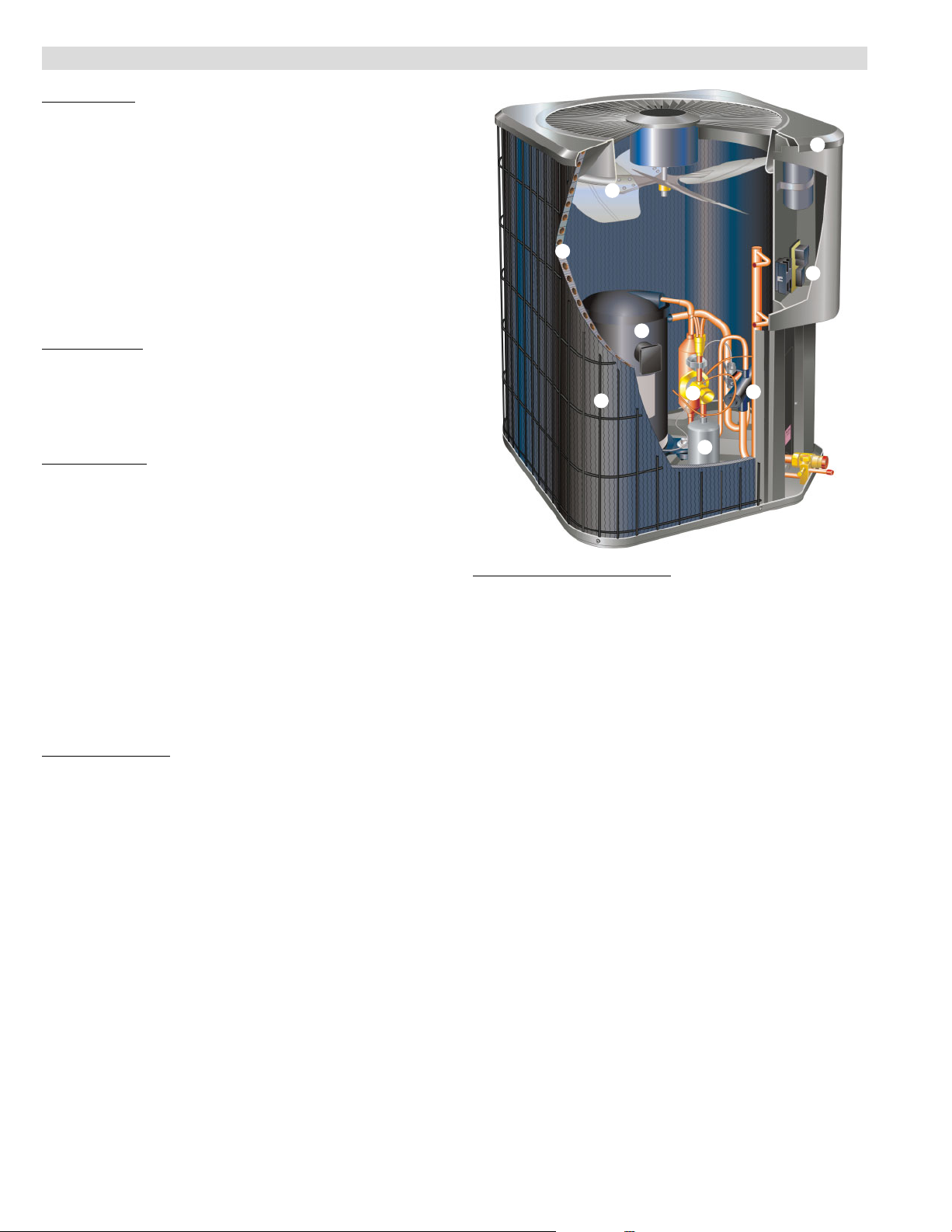
REFRIGERANT SYSTEM
Outdoor Coil Fan
B
Direct drive fan moves large air volumes uniformly
through entire outdoor coil for high refrigerant cooling and
heating capacity.
Vertical air discharge minimizes operating sounds and
eliminates damage to lawn and shrubs.
Fan motor has sleeve bearings and is inherently
protected.
Motor totally enclosed for maximum protection from
weather, dust and corrosion.
Rain shield on motor provides additional protection from
moisture.
Louvered steel top fan guard furnished as standard.
Fan service access accomplished by removal of top
panel.
Copper Tube/Enhanced Fin Coil
C
Lennox designed and fabricated coil.
Ripple-edged aluminum fins.
Copper tube construction.
Lanced fins provide maximum exposure of fin surface to
air stream resulting in excellent heat transfer.
Fin collars grip tubing for maximum contact area.
Flared shoulder tubing connections/silver soldering
construction.
Coil is factory tested under high pressure to ensure
leakproof construction.
Entire coil is accessible for cleaning.
PVC coated steel wire coil guard furnished as standard.
D
K
TP − 3 to 5 Ton R−22 Heat Pump Outdoor Units / Page 2
Page 3
FEATURES
REFRIGERANT SYSTEM (CONTINUED)
Expansion Valve − Outdoor Unit
E
Designed and sized specifically for use in heat pump
system.
Sensing bulb is located on the suction line between the
reversing valve and the compressor to sense evaporator
suction temperature in any cycle.
Factory installed and piped.
High Capacity Liquid Line Drier
F
Factory installed in the liquid line, the drier traps moisture
or dirt that could contaminate the refrigerant system.
100% molecular−sieve, bead type bi−flow drier.
Reversing Valve
G
4-way interchange reversing valve effects a rapid change
in direction of refrigerant flow resulting in quick
changeover from cooling to heating and vice versa.
Valve operates on pressure differential between outdoor
unit and indoor unit of the system. Factory installed.
OPTIONS
Check/Expansion Valve Kits
Must be ordered extra and field installed on certain indoor
units.
See ARI Ratings tables.
Chatleff−style fitting.
High Pressure Switch Kit
Protects the system from high pressure conditions that
can be a result of fan failure or a blocked/dirty coil.
Manual reset.
Loss of Charge Kit
Helps protect the compressor from damage due low
refrigerant charge conditions.
SPST, normally−closed switch, automatic reset switch
mounted on suction line.
Refrigerant Line Kits
Refrigerant lines (suction & liquid) are shipped refrigeration
clean. Lines are cleaned, dried, pressurized and sealed at
factory.
Suction line fully insulated.
Lines are stubbed at both ends.
Not available for −060 models and must be field fabricated.
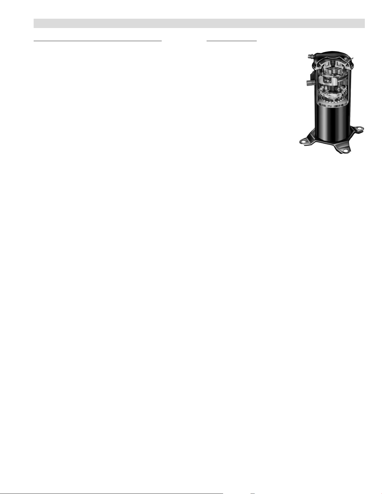
Compressor
H
Copeland Scrollt Compressor
Compressor features high
efficiency with uniform suction
flow, constant discharge flow
and high volumetric efficiency
and quiet operation.
Compressor consists of two
involute spiral scrolls matched
together to generate a series of
crescent shaped gas pockets
between them.
During compression, one scroll
remains stationary while the
other scroll orbits around it.
Gas is drawn into the outer
pocket, the pocket is sealed as
the scroll rotates.
As the spiral movement
continues, gas pockets are pushed to the center of the
scrolls. Volume between the pockets is simultaneously
reduced.
When pocket reaches the center, gas is now at high
pressure and is forced out of a port located in the center of
the fixed scrolls.
During compression, several pockets are compressed
simultaneously resulting in a smooth continuous
compression cycle.
Continuous flank contact, maintained by centrifugal force,
minimizes gas leakage and maximizes efficiency.
Scroll compressor is tolerant to the effects of slugging and
contaminants. If this occurs, scrolls separate, allowing
liquid or contaminants to to be worked toward the center
and discharged.
Low gas pulses during compression reduces operational
sound levels.
Compressor motor is internally protected from excessive
current and temperature.
Muffler in discharge line reduces operating sound levels.
Compressor is installed in the unit on resilient rubber
mounts for vibration free operation.
Compressor Crankcase Heater
Protects against refrigerant migration that can occur
during low ambient operation.
OPTIONS
Compressor Low Ambient Cut−Off
Non-adjustable switch (low ambient cut-out) prevents
compressor operation when outdoor temperature is
below 35°F.
Compressor Sound Cover
A reinforced vinyl compressor cover containing a 1−1/2
inch thick batt of fiberglass insulation.
All open edges are sealed with a one−inch wide hook and
loop fastening tape.
TP − 3 to 5 Ton R−22 Heat Pump Outdoor Units / Page 3
Page 4

FEATURES
CONTROLS
Defrost Control
I
Solid-state time/temperature defrost control is furnished
as standard equipment.
Control initiates a defrost cycle every 30, 60 or 90 minutes
of compressor on" time at outdoor coil temperatures
below 42°F (factory setting 90 minutes).
Anti−short cycle, timed−off control incorporated into the
board.
High and low pressure switch monitoring with five−trip
lockout.
Diagnostic LED’s furnished as an aid in troubleshooting.
Conveniently located in control box.
OPTIONS
Freezestat
Installs on or near the vapor line of the indoor coil or on the
suction line.
Senses suction line temperature and cycles the
compressor off when suction line temperature falls below
it’s setpoint.
Opens at 29°F and closes at 58°F.
L Connection
See L Connection Engineering Handbook Bulletin in
Controls section for details.
Low Ambient Control
Air conditioners operate satisfactorily down to 45°F
outdoor air temperature without any additional controls.
Two low ambient control options are available for field
installation.
The Low Ambient Control Kit allows unit operation down
to 30°F.
The second control option allows unit operation down to
0°F. This option requires that the outdoor fan motor and
capacitor be changed. See Low Ambient Control Option
table, page 7, for ordering information.
Freezestat should be installed on compressors equipped
with a low ambient kit.
A compressor lock−out thermostat should be added to
terminate compressor operation below recommended
operation conditions (on/off operation, 30°F or modulating
operation, 0°F).
Mild Weather Kit
Heat pump units operate satisfactorily in the heating
mode at outdoor air temperatures up to 75_F.
Mild Weather Kit can be field installed, allowing heating
operation above 75_F.
Monitor Kit − Service Light
Contains ambient compensating thermistor and service
light thermostat.
For use with thermostats requiring input for indicator lights.
Outdoor Thermostat Kit
An outdoor thermostat can be used to lock out some of the
electric heating elements on indoor units where two stage
control is applicable.
Outdoor thermostat maintains the heating load on the low
power input as long as possible before allowing the full
power load to come on the line.
Thermostat kit and mounting box must be ordered extra.
Thermostat
Thermostat not furnished with unit. See Thermostat
bulletins in Controls Section and Lennox Price Book.
®
Network
Time Delay Relay Kit
Delays the indoor blower−off time during the cooling cycle.
See ARI Rating Tables for usage.
Cabinet
J
Heavy gauge steel cabinet with five station metal wash
process.
Powder paint finish provides superior rust and corrosion
protection.
Painted base section.
Control box is conveniently located with all controls
factory wired.
Corner patch plate allows access to compressor
components.
Drainage holes are provided in base section for moisture
removal.
Refrigerant Line Connections, Electrical Inlets,
K
Service Valves
Sweat connection vapor and liquid lines are located on
corner of unit cabinet.
Fully serviceable brass service valves prevent corrosion
and provide access to refrigerant system. Vapor valve can
be fully shut off, while liquid valve may be front seated to
manage refrigerant charge while servicing system.
Refrigerant line connections and field wiring inlets are
located in one central area of cabinet for easy access. See
dimension drawing.
OPTIONS
Hail Guards
Constructed of louvered heavy gauge steel painted to
match cabinet.
Surrounds unit on all four sides to prevent damage to the
coil.
Mounting Base
Provides permanent foundation for outdoor units.
High density polyethylene structural material is
lightweight, sturdy, sound absorbing and will withstand the
rigors of the sun, heat, cold, moisture, oil and refrigerant.
Will not mildew or rot.
Can be shipped singly or in packages of 6 to a carton.
Unit Stand-Off Kit
Black high density polyethylene feet are available to raise
unit off of mounting surface away from damaging
moisture.
Four feet are furnished per order number.
TP − 3 to 5 Ton R−22 Heat Pump Outdoor Units / Page 4
Page 5
OPTIONAL CONVENTIONAL TEMPERATURE CONTROL SYSTEMS − FIElD INSTALLED
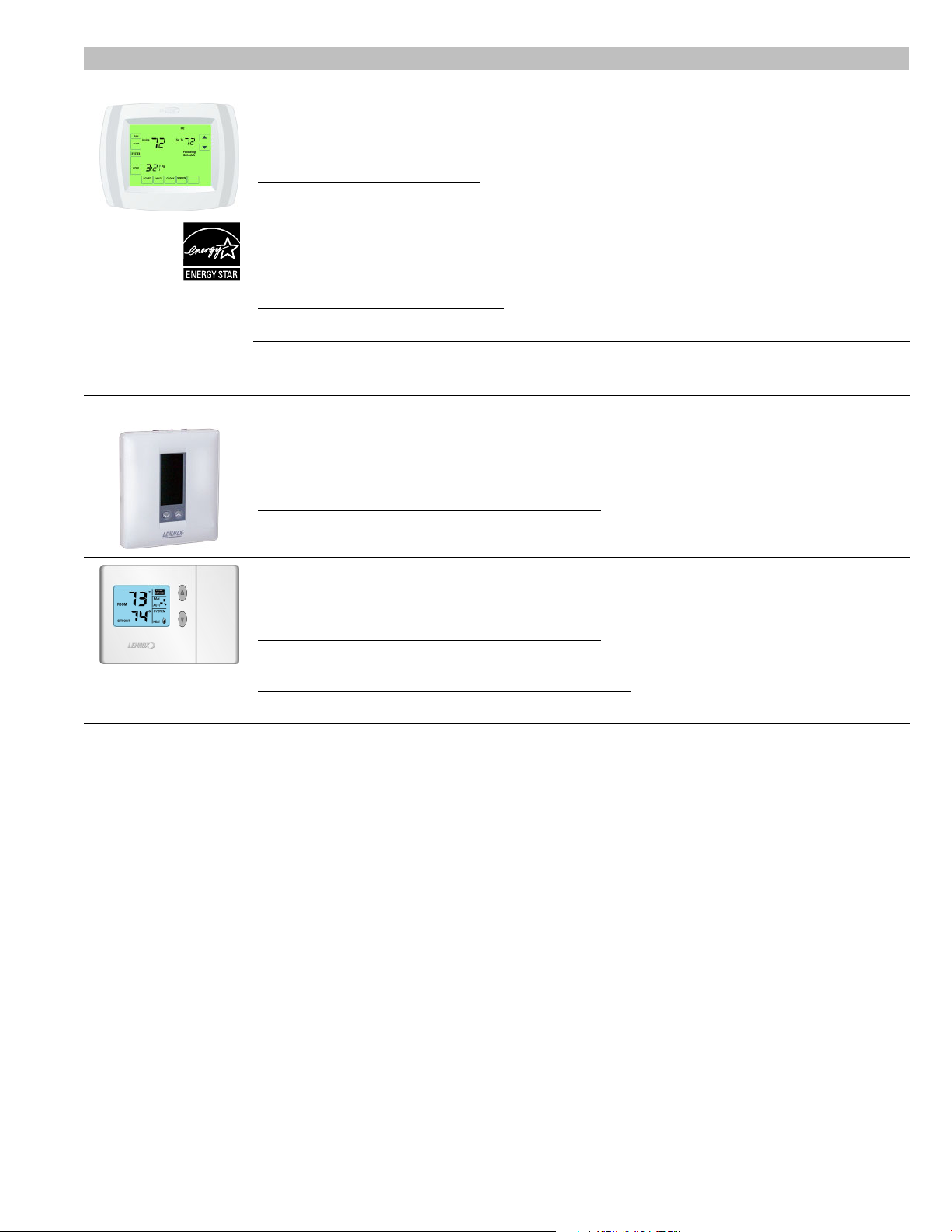
COMMERCIAL TOUCHSCREEN THERMOSTAT
Intuitive Touchscreen Interface − Two Stage Heating / Two Stage Cooling Conventional or
Heat Pump − Seven Day Programmable − Four Time Periods/Day − Economizer Output − Title 24
Compliant − E
NERGY STAR
Sensors For Touchscreen Thermostat
1
Remote non−adjustable wall mount 20k temperature sensor . . . . . . . . . . . . . . . . . . . . . . . . . . . . . . . C0SNZN01AE1−
1
Remote non−adjustable wall mount 10k averaging temperature sensor . . . . . . . . . . . . . . . . . . . . . C0SNZN73AE1−
1
Remote non−adjustable duct mount temperature sensor . . . . . . . . . . . . . . . . . . . . . . . . . . . . . . . . . . C0SNDC00AE1−
Outdoor temperature sensor . . . . . . . . . . . . . . . . . . . . . . . . . . . . . . . . . . . . . . . . . . . . . . . . . . . . . . . . . . . C0SNSR03AE1−
Accessories For Touchscreen Thermostat
Locking cover (clear) . . . . . . . . . . . . . . . . . . . . . . . . . . . . . . . . . . . . . . . . . . . . . . . . . . . . . . . . . . . . . . . . . . C0MISC15AE1−
1
Remote sensors for C0STAT02AE1L can be applied in the following combinations: (1)
C0SNZN01AE1−, (2) C0SNZN73AE1−, (2) C0SNZN01AE1− and (1) C0SNZN73AE1−, (4)
C0SNZN01AE1−, (3) C0SNZN01AE1− and (2) C0SNZN73AE1.
DIGITAL NON−PROGRAMMABLE THERMOSTATS
Intuitive Interface − Automatic Changeover − Simple Up and Down Temperature Control
Two−stage heating / cooling conventional systems . . . . . . . . . . . . . . . . . . . . . . . . . . . . . . . . . . . . . . . C0STAT10AE1L
Sensor For Digital Non−Programmable Thermostats Above
®
Qualified − Backlit Display − Automatic Changeover
C0STAT02AE1L
Remote wall mounted temperature sensor . . . . . . . . . . . . . . . . . . . . . . . . . . . . . . . . . . . . . . . . . . . . . . . C0SNZN00AE1−
Intuitive Interface − Automatic Changeover − Backlit Display − Simple Up and Down Temperature
Control
One−stage heating / cooling conventional systems . . . . . . . . . . . . . . . . . . . . . . . . . . . . . . . . . . . . . . . C0STAT12AE1L
Sensor For Digital Non−Programmable Thermostats Above
Outdoor temperature sensor . . . . . . . . . . . . . . . . . . . . . . . . . . . . . . . . . . . . . . . . . . . . . . . . . . . . . . . . . . . C0SNSR04AE1−
Accessories For Digital Non−Programmable Thermostats Above
Optional wall mounting plate . . . . . . . . . . . . . . . . . . . . . . . . . . . . . . . . . . . . . . . . . . . . . . . . . . . . . . . . . . . C0MISC17AE1−
TP − 3 to 5 Ton R−22 Heat Pump Outdoor Units / Page 5
Page 6

SPECIFICATIONS
p
g
Th
t
g
General
Data
Connections
(sweat)
2
Refrigerant R−22 charge furnished 8 lbs. 10 oz.
Outdoor
Nominal Tonnage (kW) 3 (10.6)
Liquid line o.d. − in. (mm) 3/8 (9.5) 3/8 (9.5) 3/8 (9.5)
Vapor line o.d. − in. (mm) 7/8 (22.2)
Net face area
Coil sq. ft. (m2)
Tube diameter − in. (mm) no. of rows 5/16 (8) − 2 5/16 (8) − 2 5/16 (8) − 2
Outdoor
Diameter − in. (mm) − No. of Blades 18 (457) − 4 22 (559) − 4 26 (660) − 4
Fan
Shipping Data − lbs. (kg) 1 package 178 (81) 248 (112) 284 (129)
ELECTRICAL DATA
Line voltage data − 60 hz − 3ph 208/230V 460V 208/230V 460V 208/230V 460V
3
Maximum overcurrent protection (amps) 20 10 30 15 40 15
4
Minimum circuit ampacity 13.1 6.5 20.0 9.5 23.4 10.1
Compressor
Rated Load Amps
Locked Rotor Amps
Outdoor
Fan Motor
Locked Rotor Amps
OPTIONAL ACCESSORIES − must be ordered extra
Compressor Low Ambient Cut−Off 45F08 S S S
Compressor Sound Cover 69J03 S S S
Freezestat
Hail Guards
High Pressure Switch Kit 94J46 S S S
Loss of Charge Kit 84M23 S S S
5
Low Ambient Kit (down to 30°F) 27J00 S S S
Low Ambient Control Option (down to 0°F) See table page 7 See table page 7 See table page 7
Mild Weather Kit 33M07 S S S
Monitor Kit − Service Light 76F53 S S S
Mounting Base
Outdoor
ermosta
Kit
Refrigerant
L15−65−30, L15−65−40, or L15−65−50 S S
Line Sets
Time Delay Relay Kit 58M81 S S S
Unit Stand−Off Kit 94J45 S S S
NOTE − Extremes of operating range are plus 10% and minus 5% of line voltage.
1
Sound Rating Number rated in accordance with test conditions included in ARI Standard 270.
2
Refrigerant charge sufficient for 15 ft. length of refrigerant lines.
3
HACR type circuit breaker or fuse.
4
Refer to National or Canadian Electrical Code manual to determine wire, fuse and disconnect size requirements.
5
Freezestat is recommended with Low Ambient Kit.
3/8 in. tubing 93G35 S S S
5/8 in. tubing 50A93 S S S
Thermostat 56A87 S S S
Mounting Box 31461 S
Model No. TPA036S2 TPA048S2 TPA060S2
4 (14.1) 5 (17.6)
7/8 (22.2) 1-1/8 (28.6)
(3.91 kg)
11 lbs . 1 2 o z.
(5.33 kg)
14 lbs. 0 oz.
(6.35 kg)
Outer coil 15.21 (1.41) 21.11 (1.96) 24.94 (2.32)
Inner coil 14.50 (1.35)
20.31 (1.89) 24.13 (2.24)
Fins per inch (m) 22 (866) 22 (866) 22 (866)
Motor hp (W) 208/230V − 1/5 (149)
1/3 (249) 1/3 (249)
460V − 1/6 (124)
Cfm (L/s) 2450 (1155) 3890 (1835) 4550 (2145)
Rpm 1100 1085 830
Watts 190 375 307
9.6 4.8 14.7 7.0 17.3 6.7
Power Factor
Full Load Amps
77
.96
1.1 .55 1.7 .82 1.8 .9
1.9
35 91 50 123 49.5
.88 .96 .87 .96 .88
1.1 4.1 2.2 2.9 2.3
92M89 S
92M90 S
27W36 S
69J06 S
69J07 S S
S S
Field Fabricate
S
TP − 3 to 5 Ton R−22 Heat Pump Outdoor Units / Page 6
Page 7

LOW AMBIENT CONTROL Option (Down to 0°F)
g
Model N
Rating
Order one each: Speed Control Kit, Weatherproof Kit, Outdoor Fan Motor and Capacitor
Model No. TPA036S2
TPA048S2 TPA060S2
Speed Control Kit X5867 S S S
Weatherproof Kit 56N41 S S S
Outdoor
Fan Motor
1/2 HP − 230V 69H75 S S S
460V 69H76 S
S S
Capacitor with mounting bracket 53H06 S S S
INSTALLATION CLEARANCES − INCHES (MM)
See NOTES
See
NOTES
See NOTES
See
NOTES
CONTROL
BOX
OUTDOOR SOUND DATA
1
Unit
o.
125
TPA036S2 69.5 70.5 71.5 69.5 68.5 62.5 60.5 76
TPA048S2 75.5 74.5 75 73.5 70 66.5 63.5 80
TPA060S2 76 76.5 76.5 74.5 69.5 66 61.5 80
NOTE − the octave sound power data does not include tonal correction.
1
Tested according to ARI Standard 270 test conditions.
Octave Band Sound Power Levels dBA, re 10
250 500 1000 2000 4000 8000
NOTES:
Service clearance of 30 in. (762 mm) must be maintained on one of
the sides adjacent to the control box.
Clearance to one of the other three sides must be 36 in. (914 mm)
Clearance to one of the remaining two sides may be 12 in. (305 mm)
and the final side may be 6 in. (152 mm).
A clearance of 24 in. (610 mm) must be maintained between two units.
48 in. (1219 mm) clearance required on top of unit.
−12
Center Frequency − HZ
Watts
1
Sound
Ratin
Number (dB)
TP − 3 to 5 Ton R−22 Heat Pump Outdoor Units / Page 7
Page 8

DIMENSIONS − INCHES (MM)
Model N
INLET
AIR
INLET AIR
INLET AIR
TOP VIEW
A
INLET
AIR
LIQUID LINE
CONNECTION
(Around perimeter of base)
SUCTION LINE
CONNECTION
OPTIONAL UNIT
STAND-OFF KIT (4)
(Field Installed)
COIL DRAIN OUTLETS
OUTDOOR
COIL FAN
4-3/8
(111 )
6-3/8
(162)
4-3/8
(111 )
6-3/8
(162)
COMPRESSOR
4-3/8
(111 )
4-3/8
(111 )
TOP VIEW BASE SECTION
A
DISCHARGE AIR
4-3/8
(111)
4-3/8
(111)
COMPRESSOR
BC
VAPOR &
LIQUID LINE
CONNECTIONS
ELECTRICAL
INLETS
2-3/4 (70)
2 (51)
TPA036S2
SIDE VIEW
o.
3/4
(19)
A B C
in.
mm in. mm in. mm
24-1/4 641 33-1/4 845 32-1/2 826
OPTIONAL UNIT
STAND-OFF KIT (4)
(Field Installed)
SIDE VIEW
TPA048S2 28-1/4 718 37 940 36−1/4 921
TPA060S2 32-1/4 819 37 940 36-1/4 921
TP − 3 to 5 Ton R−22 Heat Pump Outdoor Units / Page 8
Page 9

INDOOR COIL / AIR HANDLER SUBSTITUTIONS
Substituting Coils in the ARI Tables
Most R−22 and R−410A indoor coils and air handlers are the same except for the factory installed expansion device. C33
coils can be used in place of the CX34 coils, CB26UH, CB30M and CB31MV air handlers can be used in place of the
CB26XUH, CBX32M and CBX32MV, respectively.
The expansion device is based on the size of the outdoor unit. The factory installed RFC or TXV on the
C33/CB26UH/CB31MV/CB30M must be replaced to correspond to the outdoor unit. The correct TXV’s are:
3 ton air conditioners 56J19
4−5 ton air conditioners 56J20
Example:
A four−ton air conditioner is being installed. The ARI table shows that CBX32MV−048 is a matching air handler. A
CB31MV−51 with a 56J20 TXV can be used in its place.
UP−FLOW COILS
CX34−18/24A−6F
CX34−18/24B−6F =
CX34−18/24C−6F =
CX34−44/48B−6F
CX34−44/48C−6F
R−410A R−22
=
C33−24A−2
C33−24B−2
C33−24C−2
CX34−19A−6F
CX34−25A−6F
CX34−25B−6F
CX34−30A−6F
CX34−30B−6F
CX34−30C−6F
CX34−31A−6F
CX34−31B−6F
CX34−36A−6F
CX34−36B−6F
CX34−36C−6F
CX34−38A−6F
CX34−38B−6F
CX34−42B−6F = C33−42B−2
CX34−43B−6F = C33−43B−2
CX34−43C−6F = C33−43C−2
no equivalent
CX34−49C−6F
CX34−50/60C−6F
CX34−60D−6F
CX34−62C−6F
CX34−62D−6F
=
C33−19A−2
=
C33−25A−2
=
C33−25B−2
=
C33−30A−2
=
C33−30B−2
=
C33−30C−2
=
C33−31A−2
=
C33−31B−2
=
C33−36A−2
=
C33−36B−2
=
C33−36C−2
=
C33−38A−2
=
C33−38B−2
C33−44C−2
=
C33−48B−2
=
C33−48C−2
=
C33−49C−2
=
C33−50/60C−2
=
C33−60D−2
=
C33−62C−2
=
C33−62D−2
AIR HANDLERS
R−410A R−22
CBX26UH−018
CBX26UH−024 = CB26UH−024
CBX26UH−030 = CB26UH−030
CBX26UH−036
CBX26UH−042 = CB26UH−042
CBX26UH−048 = CB26UH−048
CBX26UH−060
CBX27UH−018/024 = CB27UH−018/024
CBX27UH−030 = CB27UH−030
CBX27UH−036
CBX27UH−042 = CB27UH−042
CBX27UH−048 = CB27UH−048
CBX27UH−060
CBX32M−018/024 = CB30M−21/26
CBX32M−030 = CB30M−31
CBX32M−036
CBX32M−042 = CB30M−46
CBX32M−048 = CB30M−51
CBX32M−060
CBX32MV−018/024 no equivalent
CBX32MV−024/030 no equivalent
CBX32MV−036
CBX32MV−048 = CB31MV−51
CBX32MV−060 = CB31MV−65
CBX32MV−068
= CB26UH−018
= CB26UH−036
= CB26UH−060
= CB27UH−036
= CB27UH−060
= CB30M−41
= CB30M−65
= CB31MV−41
no equivalent
TP − 3 to 5 Ton R−22 Heat Pump Outdoor Units / Page 9
Page 10

ARI RATINGS
Expansion
Cooli
Cool
High
Low
High
Low
1
ARI Standard 210/240 Ratings
Capacity − Btuh Efficiency Tota l Wat ts COP
ng
High
Tem p.
Heating
Low
Tem p.
Heating
HSPF
SEER EER IV V
High Low High Low
Heat
Heat
Heat
Heat
TPA036S2 3 TON
Air Handlers Air Handlers
34,400 33,600 20,800 13.00 11. 00 7.70 6.75 3150 2825 2695 3.48 2.263 CB30M−41 (Multi−Position) Factory TXV
34,400 33,600 20,800 13.00 11. 00 7.70 6.70 3155 2830 2710 3.48 2.243 CB30U−41/46 (Up−Flow) Factory TXV
34,400 34,000 21,200 12.20 10.40 7.70 6.70 3245 2925 2755 3.40 2.26
34,600 33,600 20,800 13.00 11. 00 7.70 6.80 3130 2790 2670 3.52 2.283 CB30M−46 (Multi−Position) Factory TXV
34,600 34,200 21,600 12.00 10.30 7.50 6.60 3350 3045 2840 3.24 2.223 CB29M−51 (Multi−Position) Factory TXV
34,800 33,400 20,800 13.00 11. 00 7.70 6.80 3125 2765 2650 3.54 2.304 CB31MV−41 (Multi−Position) Factory TXV
34,800 33,200 20,600 13.50 11. 00 7.70 6.70 3165 2705 2570 3.60 2.34
35,200 33,800 21,000 13.00 11. 00 7.70 7.10 3165 2760 2515 3.58 2.445 CB26UH−036 (Up−Flow/Horiz.) Factory TXV
36,400 33,000 20,400 14.00 12.00 7.70 6.70 3035 2700 2505 3.58 2.38
Up−Flow Indoor Coils + Furnaces Up−Flow Coils + Furnaces
34,200 33,200 20,600 13.00 11. 00 7.70 6.80 3080 2875 2610 3.38 2.32 C33−36B
34,200 33,200 20,600 13.00 11. 00 7.70 6.75 3065 2885 2615 3.38 2.30 C33−36C
34,200 33,200 20,600 13.00 11. 00 7.70 6.80 3080 2875 2610 3.38 2.32 C33−42B
34,400 33,200 20,800 13.00 11. 00 7.70 6.80 3100 2865 2615 3.40 2.32 C33−36C
34,600 33,200 20,600 13.00 11. 00 7.70 6.85 3085 2840 2590 3.42 2.32 C33−36C
34,600 33,200 20,800 13.00 11. 00 7.70 6.80 3095 2850 2605 3.42 2.34 C33−36C
Down−Flow Indoor Coils + Furnaces Down−Flow Coils + Furnaces
34,600 33,400 20,800 13.00 11. 00 8.20 7.20 3060 2675 2425 3.66 2.52 CR33−30/36B−F4 G60DFV−36B−0902 56J19
34,600 33,400 20,800 13.00 11. 00 8.20 7.20 3075 2695 2435 3.64 2.50 CR33−30/36C−F4 G61MPV−36C−0902 56J19
34,600 33,200 20,600 13.00 11. 00 7.70 7.05 3060 2760 2495 3.52 2.42 CR33−48B−F
34,800 33,600 20,800 13.00 11. 00 8.20 7.20 3105 2680 2440 3.68 2.50 CR33−30/36C−F4 G61MPV−60C−0902 56J19
35,000 33,600 20,800 13.00 11. 00 8.20 7.25 3100 2665 2430 3.70 2.50 CR33−30/36C−F4 G61MPV−60C−1102 56J19
Horizontal Indoor Coils + Furnaces Horizontal Coils + Furnaces
34,000 33,200 20,800 13.00 11. 00 7.70 7.00 3075 2785 2510 3.50 2.42 CH23−41
34,000 33,200 20,800 13.00 11. 00 7.70 7.00 3065 2795 2510 3.48 2.42 CH23−41
34,400 33,400 20,800 13.00 11. 00 7.70 7.05 3090 2765 2505 3.54 2.44 CH23−41
34,600 33,200 20,600 13.00 11. 00 7.70 6.80 3075 2835 2625 3.44 2.30 CH33−36C−2F
34,800 33,400 20,800 13.00 11. 00 7.70 6.80 3100 2810 2625 3.48 2.32 CH33−36C−2F
35,000 33,400 20,800 13.00 11. 00 7.70 6.85 3100 2800 2615 3.50 2.32 CH33−36C−2F
NOTE − These are the only approved system match−ups. For other matches, contact the Lennox Applications Department.
NOTE − Ratings for C33 coils include all cased and uncased coils.
NOTE − When used with gas furnaces, a dual−fuel control (i.e. FM21) or a control system with dual−fuel capabilities (i.e. Harmony III, LZP−2 or LZP−4) must be used (ordered extra).
1
Certified in accordance with USE certification program which is based on ARI Standard 210/240 with 25 ft. (7.6 m) of connecting refrigerant lines;
Cooling Ratings − 95_F (35_C) outdoor air temperature and 80_F (27_C) db/67_F (19_C) wb entering indoor coil air.
High Temperature Heating Ratings − 47_F (8_C) db/43_F (6_C) wb outdoor air temperature and 70_F (21_C) db entering indoor coil air.
Low Temperature Heating Ratings − 17_F (−8.3_C) db/15_F (−9.4_C) wb outdoor air temperature and 70_F (21_C) db entering indoor coil air.
2
Factory installed expansion valve or RFC on indoor unit MUST be replaced with valve specified (if equipped).
3
Blower must be capable of time−off blower delay. Indoor Blower Off Delay Relay (58M81) is recommend for field installation.
4
Blower control must be set for a time−off blower delay.
5
Most popular air handler combination.
Indoor Unit Model No.
3,6
CB29M−46 (Multi−Position) Factory TXV
4
CB27UH−036 (Up−Flow / Horizontal) Factory TXV
4
CB27UH−042 (Up−Flow / Horizontal)
4
G60UHV−36B−0902 56J19
4
G61MPV−36C−0902 56J19
4
G60UHV−36B−0902 56J19
4
G61MPV−60C−0902 56J19
4
G60UHV−60C−1102 56J19
4
G61MPV−60C−1102 56J19
4
G60DFV−36B−0902 56J19
4
G60UHV−36B−0902 56J19
4
G61MPV−36C−0902 56J19
4
G61MPV−60C−1102 56J19
4
G61MPV−36C−0902 56J19
4
G61MPV−60C−0902 56J19
4
G61MPV−60C−1102 56J19
Device
2
56J19
TP − 3 to 5 Ton R−22 Heat Pump Outdoor Units / Page 10
Page 11

ARI RATINGS
Expansion
Cooli
Cool
High
Low
High
Low
1
ARI Standard 210/240 Ratings
Capacity − Btuh Efficiency Total Wa tts COP
ng
High
Tem p.
Heating
Low
Tem p.
Heating
HSPF
SEER EER IV V
High Low High Low
Heat
Heat
Heat
Heat
TPA048S2 4 TON
Air Handlers Air Handlers
46,000 46,000 29,800 11 .4 0 10.00 7.85 7.05 4590 4080 3620 3.30 2.42
46,500 45,500 29,600 11 .6 0 10.20 7.90 7.10 4530 4020 3560 3.32 2.443 CB29M−65 (Multi−Position) Factory TXV
49,000 47,500 30,200 13.00 11. 00 8.50 7.50 4455 3660 3420 3.80 2.58
49,500 47,500 30,200 13.00 11. 00 8.50 7.50 4500 3690 3435 3.78 2.584 CB27UH−048 (Up−Flow / Horizontal) Factory TXV
49,500 47,500 30,600 13.00 11. 00 7.70 7.40 4455 3775 3525 3.68 2.543 CB30M−51 (Multi−Position) Factory TXV
50,000 47,000 30,000 13.50 11. 50 7.70 7.50 4350 3650 3400 3.78 2.584 CB31MV−51 (Multi−Position) Factory TXV
50,500 47,500 30,600 13.00 11. 00 7.70 7.10 4520 4075 3685 3.42 2.445 CB26UH−048 (Up−Flow/Horiz.) Factory TXV
Up−Flow Indoor Coils + Furnaces Up−Flow Coils + Furnaces
49,000 47,500 30,600 13.00 11. 00 7.70 7.10 4450 4050 3675 3.44 2.44 C33−50/60C
49,500 47,500 30,600 13.00 11. 00 7.70 7.10 4470 4040 3670 3.44 2.44 C33−49C
49,500 47,500 30,600 13.00 11. 00 7.70 7.10 4465 4030 3660 3.46 2.44 C33−49C
49,500 47,500 30,400 13.00 11. 00 7.70 7.10 4455 4030 3655 3.46 2.44 C33−50/60C
50,000 47,500 30,400 13.00 11. 00 7.70 7.15 4430 3975 3620 3.50 2.46 C33−49C
50,000 47,000 30,400 13.00 11. 00 7.70 7.15 4420 3995 3620 3.44 2.46 C33−49C
50,000 47,000 30,000 13.50 11. 00 7.70 7.20 4360 3925 3535 3.50 2.48 C33−60D
50,000 47,000 30,400 13.00 11. 00 7.70 7.20 4410 3965 3585 3.48 2.48 C33−60D
51,000 47,500 30,400 13.50 11. 00 7.70 7.10 4480 4055 3640 3.44 2.44 C33−62C
51,000 47,500 30,600 13.00 11. 00 7.70 7.05 4525 4100 3685 3.40 2.44 C33−62C
51,000 47,500 30,600 13.00 11. 00 7.70 7.05 4520 4095 3680 3.40 2.44 C33−62C
51,500 47,500 30,400 13.50 11. 50 7.70 7.10 4480 4035 3625 3.46 2.46 C33−62C
Down−Flow Indoor Coils + Furnaces Down−Flow Coils + Furnaces
49,000 47,500 30,200 13.00 11. 00 7.70 7.50 4400 3685 3440 3.78 2.58 CR33−50/60C−F4 G60DFV−60C−1102 56J20
49,000 47,500 30,400 13.00 11. 00 7.70 7.40 4450 3760 3510 3.70 2.54 CR33−50/60C−F4 G61MPV−60C−1102 56J20
49,000 47,500 30,200 13.00 11. 00 7.70 7.50 4395 3680 3435 3.78 2.58 CR33−60D−F
49,000 47,500 30,400 13.00 11. 00 7.70 7.50 4395 3705 3455 3.76 2.58 CR33−60D−F
49,500 47,500 30,400 13.00 11. 00 7.70 7.50 4415 3680 3445 3.78 2.58 CR33−50/60C−F4 G60DFV−60C−0902 56J20
Horizontal Indoor Coils + Furnaces Horizontal Coils + Furnaces
50,000 47,500 30,400 13.00 11. 00 7.70 7.15 4460 4020 3625 3.46 2.46 CH33−50/60C−2F4 G60UHV−60C−1102 56J20
50,000 47,500 30,600 13.00 11. 00 7.70 7.10 4505 4065 3670 3.42 2.44 CH33−50/60C−2F4 G61MPV−60C−0902 56J20
50,000 47,500 30,600 13.00 11. 00 7.70 7.10 4505 4045 3665 3.44 2.44 CH33−50/60C−2F4 G61MPV−60C−1102 56J20
50,000 47,000 30,200 13.50 11. 00 7.70 7.20 4360 3925 3550 3.50 2.50 CH33−60D−2F
50,000 47,000 30,400 13.00 11. 00 7.70 7.15 4410 3965 3585 3.48 2.48 CH33−60D−2F
50,500 47,500 30,200 13.50 11. 50 7.70 7.65 4365 3530 3355 3.94 2.64 CH23−68
50,500 47,500 30,200 13.50 11. 00 7.70 7.60 4420 3570 3400 3.90 2.60 CH23−68
50,500 47,500 30,600 13.00 11. 00 7.70 7.15 4465 3985 3615 3.50 2.48 CH33−50/60C−2F4 G60UHV−60C−0902 56J20
NOTE − These are the only approved system match−ups. For other matches, contact the Lennox Applications Department.
NOTE − Ratings for C33 coils include all cased and uncased coils.
NOTE − When used with gas furnaces, a dual−fuel control (i.e. FM21) or a control system with dual−fuel capabilities (i.e. Harmony III, LZP−2 or LZP−4) must be used (ordered extra).
1
Certified in accordance with USE certification program which is based on ARI Standard 210/240 with 25 ft. (7.6 m) of connecting refrigerant lines;
Cooling Ratings − 95_F (35_C) outdoor air temperature and 80_F (27_C) db/67_F (19_C) wb entering indoor coil air.
High Temperature Heating Ratings − 47_F (8_C) db/43_F (6_C) wb outdoor air temperature and 70_F (21_C) db entering indoor coil air.
Low Temperature Heating Ratings − 17_F (−8.3_C) db/15_F (−9.4_C) wb outdoor air temperature and 70_F (21_C) db entering indoor coil air.
2
Factory installed expansion valve or RFC on indoor unit MUST be replaced with valve specified (if equipped).
3
Blower must be capable of time−off blower delay. Indoor Blower Off Delay Relay (58M81) is recommend for field installation.
4
Blower control must be set for a time−off blower delay.
5
Most popular air handler combination.
Indoor Unit Model No.
3,6
CB29M−51 (Multi−Position) Factory TXV
4
CB27UH−060 (Up−Flow / Horizontal) Factory TXV
4
G60UHV−60C−1102 56J20
4
G61MPV−60C−0902 56J20
4
G61MPV−60C−1102 56J20
4
G60UHV−60C−0902 56J20
4
G60UHV−60C−0902 56J20
4
G60UHV−60C−1102 56J20
4
G60UHV−60D−1352 56J20
4
G61MPV−60D−1352 56J20
4
G60UHV−60C−1102 56J20
4
G61MPV−60C−0902 56J20
4
G61MPV−60C−1102 56J20
4
G60UHV−60C−0902 56J20
4
G60DFV−60D−1352 56J20
4
G61MPV−60D−1352 56J20
4
G60UHV−60D−1352 56J20
4
G61MPV−60D−1352 56J20
4
G60UHV−60D−1352 56J20
4
G61MPV−60D−1352 56J20
Device
TP − 3 to 5 Ton R−22 Heat Pump Outdoor Units / Page 11
Page 12

ARI RATINGS
Expansion
Cooli
Cool
High
Low
High
Low
1
ARI Standard 210/240 Ratings
Capacity − Btuh Efficiency Total Wa tts COP
ng
High
Tem p.
Heating
Low
Tem p.
Heating
HSPF
SEER EER IV V
High Low High Low
Heat
Heat
Heat
Heat
TPA060S2 5 TON
Air Handlers Air Handlers
54,000 55,500 35,600 13.00 11. 00 7.70 6.70 4910 4595 4130 3.54 2.52
56,000 55,000 35,400 13.00 11. 00 7.70 6.70 5090 4660 4145 3.46 2.504 CB31MV−51 (Multi−Position) Factory TXV
57,000 55,000 35,800 13.00 11. 00 7.70 6.70 5180 4765 4240 3.42 2.483 CB30U−65 (Up−Flow) Factory TXV
57,000 55,500 35,800 13.00 11. 00 7.70 6.70 5180 4795 4265 3.40 2.46
57,000 55,500 35,800 13.00 11. 00 7.70 6.70 5180 4730 4230 3.44 2.483 CB30M−65 (Multi−Position) Factory TXV
57,500 55,000 35,400 13.00 11. 50 7.70 6.70 5000 4655 4155 3.46 2.504 CB31MV−65 (Multi−Position) Factory TXV
Up−Flow Indoor Coils + Furnaces Up−Flow Coils + Furnaces
55,000 55,000 35,600 13.00 11. 50 7.70 6.70 4785 4940 4365 3.26 2.38 C33−60D
55,500 55,000 35,600 13.00 11. 50 7.70 6.70 4825 4855 4290 3.32 2.42 C33−60D
56,000 55,500 36,000 13.00 11. 00 7.70 6.70 5090 4995 4455 3.26 2.36 C33−62C
56,000 55,000 35,600 13.00 11. 50 7.70 6.70 4870 4920 4335 3.28 2.40 C33−62D
56,500 55,500 35,800 13.00 11. 50 7.70 6.70 4915 4950 4400 3.28 2.38 C33−62C
56,500 55,000 35,600 13.50 11. 50 7.70 6.70 4915 4835 4275 3.34 2.44 C33−62D
56,500 55,500 36,000 13.00 11. 00 7.70 6.70 5135 4975 4445 3.26 2.38 C33−62C
57,000 55,500 35,800 13.00 11. 50 7.70 6.70 4955 4895 4390 3.32 2.38 C33−62C
Down−Flow Indoor Coils + Furnaces Down−Flow Coils + Furnaces
53,500 55,000 35,400 13.00 11. 00 7.70 6.70 4865 4695 4155 3.44 2.50 CR33−50/60C−F4 G60DFV−60C−0902 56J20
54,000 55,000 35,600 13.00 11. 00 7.70 6.70 4910 4670 4145 3.46 2.52 CR33−60D−F
Horizontal Indoor Coils + Furnaces Horizontal Coils + Furnaces
55,000 55,000 35,600 13.00 11. 50 7.70 6.70 4785 4990 4365 3.24 2.38 CH33−60D−2F
55,000 55,000 35,600 13.00 11. 50 7.70 6.70 4785 4935 4370 3.26 2.38 CH33−62D−2F
55,500 55,000 35,600 13.00 11. 50 7.70 6.70 4825 4895 4305 3.30 2.42 CH33−60D−2F
55,500 55,500 35,600 13.00 11. 50 7.70 6.70 4825 4540 4100 3.58 2.54 CH23−68
56,000 54,500 35,400 13.50 11. 50 7.70 6.70 4870 4895 4300 3.26 2.42 CH33−62D−2F
56,500 55,500 35,600 13.50 11. 50 7.70 6.70 4915 4470 4040 3.64 2.58 CH23−68
57,500 55,000 35,600 13.00 11. 00 7.70 6.70 5225 5000 4415 3.26 2.38 CH33−50/60C−2F4 G60UHV−60C−0902 56J20
57,500 55,000 35,800 13.00 11. 00 7.70 6.70 5225 5015 4395 3.22 2.38 CH33−50/60C−2F4 G60UHV−60C−1102 56J20
NOTE − These are the only approved system match−ups. For other matches, contact the Lennox Applications Department.
NOTE − Ratings for C33 coils include all cased and uncased coils.
NOTE − When used with gas furnaces, a dual−fuel control (i.e. FM21) or a control system with dual−fuel capabilities (i.e. Harmony III, LZP−2 or LZP−4) must be used (ordered extra).
1
Certified in accordance with USE certification program which is based on ARI Standard 210/240 with 25 ft. (7.6 m) of connecting refrigerant lines;
Cooling Ratings − 95_F (35_C) outdoor air temperature and 80_F (27_C) db/67_F (19_C) wb entering indoor coil air.
High Temperature Heating Ratings − 47_F (8_C) db/43_F (6_C) wb outdoor air temperature and 70_F (21_C) db entering indoor coil air.
Low Temperature Heating Ratings − 17_F (−8.3_C) db/15_F (−9.4_C) wb outdoor air temperature and 70_F (21_C) db entering indoor coil air.
2
Factory installed expansion valve or RFC on indoor unit MUST be replaced with valve specified (if equipped).
3
Blower must be capable of time−off blower delay. Indoor Blower Off Delay Relay (58M81) is recommend for field installation.
4
Blower control must be set for a time−off blower delay.
5
Most popular air handler combination.
Indoor Unit Model No.
4
CB27UH−060 (Up−Flow / Horizontal) Factory TXV
5
CB26UH−060−R (Up−Flow / Horizontal)2 56J20
4
G61MPV−60D−1352 56J20
4
G60UHV−60D−1352 56J20
4
G61MPV−60C−0902 56J20
4
G61MPV−60D−1352 56J20
4
G60UHV−60C−1102 56J20
4
G60UHV−60D−1352 56J20
4
G61MPV−60C−1102 56J20
4
G60UHV−60C−0902 56J20
4
G60DFV−60D−1352 56J20
4
G61MPV−60D−1352 56J20
4
G61MPV−60D−1352 56J20
4
G60UHV−60D−1352 56J20
4
G61MPV−60D−1352 56J20
4
G60UHV−60D−1352 56J20
4
G60UHV−60D−1352 56J20
Device
TP − 3 to 5 Ton R−22 Heat Pump Outdoor Units / Page 12
Page 13

Page 14

Page 15

REVISIONS
Sections Description of Change
Ratings Revised TPA060 ratings
Page 16
Visit us at www.lennox.com
For the latest technical information, www.lennoxdavenet.com
Contact us at 1−800−9−LENNOX
NOTE − Due to Lennox’ ongoing committment to quality, Specifications, Ratings and Dimensions subject to change without notice and without incurring liability.
Improper installation, adjustment, alteration, service or maintenance can cause property damage or personal injury.
Installation and service must be performed by a qualified installer and servicing agency.
©2007 Lennox Industries Inc.
 Loading...