

Lennox THXD 090, THXD 045, THX 056, THXD 073, THX 090 Installation, Operating And Maintenance Instructions
...Page 1

www.lennoxemea.com
INSTALLATION, OPERATING
AND MAINTENANCE
WALL MOUNTED PACKAGED
INDOOR UNIT
@DNOVA
THX
4 - 15 kW
ADNOVA-THX_R410A-
IOM-1506-E
Page 2

Page 3

@DNOVA THX_R410A-IOM-1506-E 1
1 General Description 2
1.1 Structure 2
1.2 Field of application 2
1.3 Cooling circuit 3
1.4 Installation warnings 4
2 Inspection / Transport / Positioning 5
2.1 Inspection on receipt 5
2.2 Lifting and Transport 5
2.3 Unpacking 5
2.4 Positioning 5
3 Installation 10
4 Evacuation and Charging Operations 10
4.1 Introduction 10
4.2 Vacuum and charging machine 10
4.3 Evacuating a circuit “contaminated” with refrigerant 11
4.4 Charging positions (single point ) 11
5 Electrical Connections 12
5.1 Generalities 12
6 Machine Functional Schemes 13
7 Starting Up 14
7.1 Preliminary checks 14
7.2 Starting up instructions (for THX/D packaged air---conditioning uni ts ) 14
8 Setting Operating Parameters 17
8.1 Generalities 17
8.2 Maximum pressure switch 17
8.3 Minimum pressure switch 17
9 Maintenance 18
9.1 Warnings 18
9.2 Generalities 18
9.3 General inspection 19
9.4 Inspecting the air filter (THX) 19
9.5 Inspecting the air filter (THXD) 20
9.6 Inspecting the damper/motor (THXD) 20
9.7 Inspecting the damper/motor (THX) 22
9.8 Fixing of cables 22
9.9 Inspection of the compressor section 23
9.10 Inspection the sight glass and the filter drier 23
9.11 Repairing the cooling circuit 24
9.12 Tightness test 24
9.13 Hard vacuum and drying of cooling circuit 24
9.14 Recharging with refrigerant R410A 25
9.15 Environmental protection 25
10 Troubleshooting 26
11 Dimensional drawing 27
Page 4

@DNOVA THX_R410A-IOM-1506-E 2
1 GENERAL DESCRIPTION
THX/D “Lennox Wall-mounted T elecom units ” are a ir c onditioner s f or low- and medium -powered t eleph one
exchanges. They are desi gned to be mounted on an outside wal l of the shelter.THX air conditioners are
direct expansion package units with an air-cooled condenser system. They are distinguished by an
innovative air circulation system which significantly enhances performance in all operating conditions.
1.1 Structure
All THX/D units have a gal vanised sheet st eel supporting base, c oated with epo xy polyester powder paint
oven cured at 180°C, an d e nc losin g p ane ls made of aluminium and m agnes ium alloy 5005 (Peraluman) or,
on request, painted galvanised sheet steel (RALxxxx). The unit features an exclusive design which,
combined with a rational la yout of components and extrem ely compact dimensions, lends it an attrac tive
appearance.
1.2 Field of application
THX/D units are to be use d within the operating limits st ated in this manual; failure to com ply with said
limits will invalidate the warranties provided in the contract of sale (see Tab. 1)
Tab. 1 Operating limits
Modello
THX
045
THXD
045
THX
056
THXD
056
THX
073
THXD
073
THX
090
THXD
090
THX
105
THXD
105
THX
120
THXD
120
THX
145
THXD
145
THX
230
THX 290
Alimentazione
elettrica
230Vac 10%
24Vdc 16% / 48Vdc 16%
400Vac 10% / 3Ph + N /
50Hz
24Vdc 16% / 48Vdc 16%
Condizioni
ambientali
esterne min.
- 20 °C
Condizioni
ambientali
esterne max.
48,0 °C 46,5 °C 45,0 °C 47,0 °C 45,0 °C 46,0 °C 48,0 °C
48,0 °C 46,0 °C
Condizioni
ambientali
interne min. /
Umidità
19 °C / 30 % U.R.
Condizioni
ambientali
interne max. /
Umidità
35 °C / 50 % U.R.
Condizioni di
immagazzinamento
-10 °C / 90 % U.R.
+55 °C / 90 % U.R.
Page 5
@DNOVA THX_R410A-IOM-1506-E 3
1.3 Cooling circuit
The entire cooling circ uit is built in the Lennox factory using on ly components of the f inest quality brands
and processes conforming to the specifications of Directive 97/23 for brazing and tes tin g.
Compressors: onl y scroll-t ype com pres sors of lead ing internati onal m anuf actur ers are used in th e THX
units. Today scroll compressors represent the best solution in terms of reliability, efficiency and MTBF.
Cooling components:
o Molecular mesh activated-alumina filter dryer
o Flow indicator with humidity indicator. Indications are provided directly on the sight glass.
o Thermostatic valve with external equalization and integrated MOP function.
o High and low pressure switches
o Schrader valves for checks and/or maintenance
Electric control board: The electric contr ol boar d is c on s tr uct ed an d wired i n ac c or danc e with D irec t ives
73/23/EEC and 89/33 6/EEC and related s tandards. The boar d may be acces sed through a door af ter
the main switch has been put of f. All the remote controls use 24 V s ignals powered by an insulating
transformer situated on the electric control boar d. NOTE: the mechanical safety dev ices such as the
high pressure switch are of the kind that trigger directly; their efficiency will not be affected by any faults
occurring in the microprocessor control circuit, in compliance with 97/23 PED.
Control microprocessor: the microprocessor built into the unit allows the different operating parameters
to be controlled from a set of pushbuttons situated on the electric control board;
o Switching on/off of compressor to maintain the temperature set point T inside the shelter
o Alarm management
High / low pressure
Dirty filters alarm
Air flow alarm
o Alarm signalling
o Display of operating parameters
o RS232, RS485 serial output management (optional)
o Phase sequence error [Not displayed by the mP, but prevents the compressor from starting up]
[see microprocessor control manual for further details, also in relation to particular customer
specifications]
Page 6
@DNOVA THX_R410A-IOM-1506-E 4
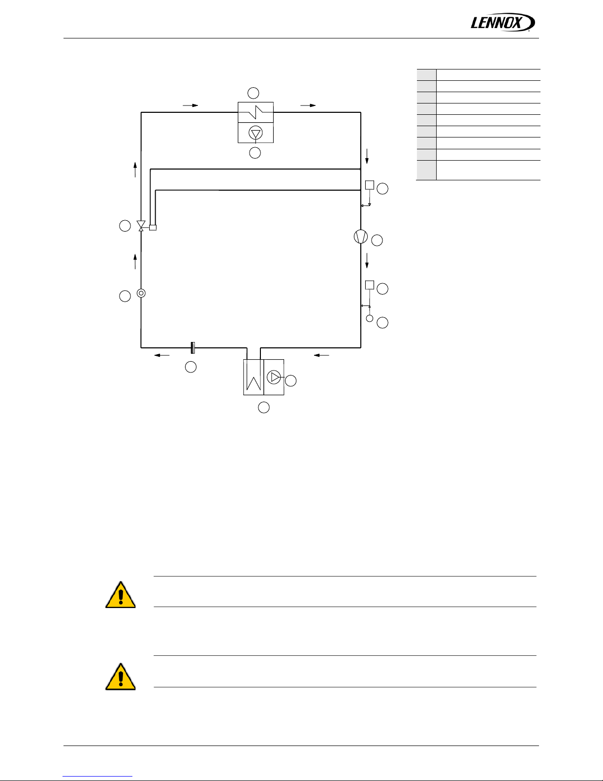
Fig. 1 Basic cooling cir cuit
1
Compressor
2
Condenser
3
Thermostatic valve
4
Evaporator
5
Filter dryer
6
Sight glass
7
Low pressure switch
8
High pressure switch
9
Condensing pressure
probe
1.4 Installation warnings
General rules
• When installing or servicing the unit, you must strictly follow the rules provided in this manual, comply with
the directions on the units themselves and take all such precautions as are necessary.
• The fluids under pressure in t he cooling circuit and the presence of electrical components may cause
hazardous situations during installation and maintenance work.
All work on the unit must be carried out by qualified personnel only, trained to do
their job in accordance with current laws and regulations
• Failure to com ply with the r ules provided in this m anual or an y modificatio n made to the unit withou t prior
authorisation will result in the immediate invalidation of the warranty.
Warning: Before performing any kind of work on the unit, make sure it has been
disconnected from the power supply.
P
P 1 2 3 5
6 7 8
9
4 M M
Page 7
@DNOVA THX_R410A-IOM-1506-E 5
2 Inspection / Transport / Positioning
2.1 Inspection on receipt
On receiving the unit, check that it is perfectly intact: the unit left the factory in perfect conditions;
immediately report a ny signs of damage to the carrier and note them on the Delivery Slip bef ore signing
it.Lennox or its Agent m ust be promptly notif ied of the entit y of the damage. T he Customer m ust submit a
written report describing every significant sign of damage.
2.2 Lifting and Transport
While the unit is being unloaded and positioned, utmost care must be taken to avoid abrupt or violent
manoeuvres. The unit must be handled carefully and gently; avoid using machine components as
anchorages or holds and al wa ys keep it in an upr igh t positi on. The unit should be lifted using t he pallet i t is
packed on; a transpallet or similar conveyance means should be used
Warning: In all lifting operations make sure that the unit is securely anchored in order to
prevent accidental falls or overturning.
2.3 Unpacking
The packing mus t be carefully removed to a void the risk of damaging the uni t. Different pack ing materials
are used: wood, cardboard, nylon etc. It is recommended to keep them separately and deliver them to
suitable waste disposal or recycling facilities in order to minimise their environmental impact.
2.4 Positioning
Bear in mind the following aspects when choosing the best site for installing the unit and the relative
connections:
• positioning and dimensions of the coupling flanges;
• location of power supply;
• solidity of the supporting wall;
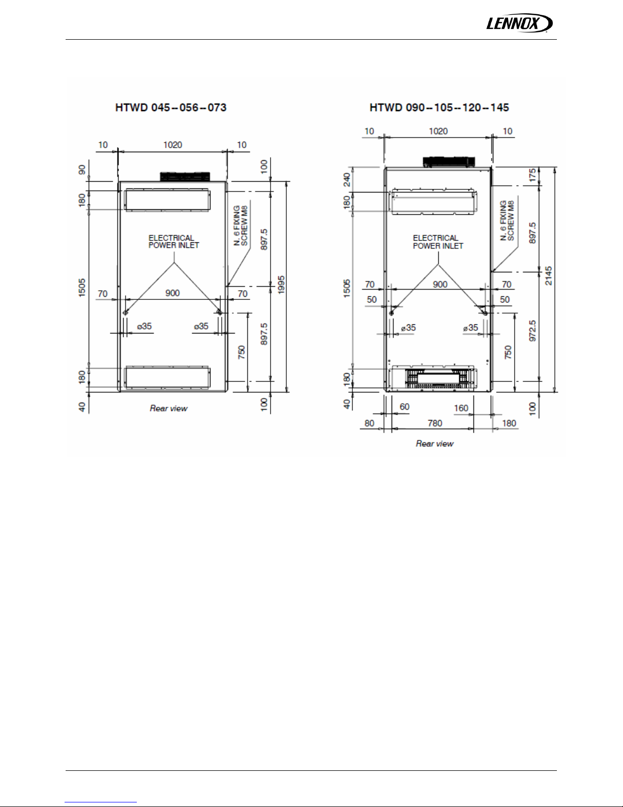
It is recommended to f irst p repare h oles in the w all for pas sing thr ough t he po wer c ables, for the air intak e
and outlet flanges and for the screw anchors that will secure the unit on the wall.
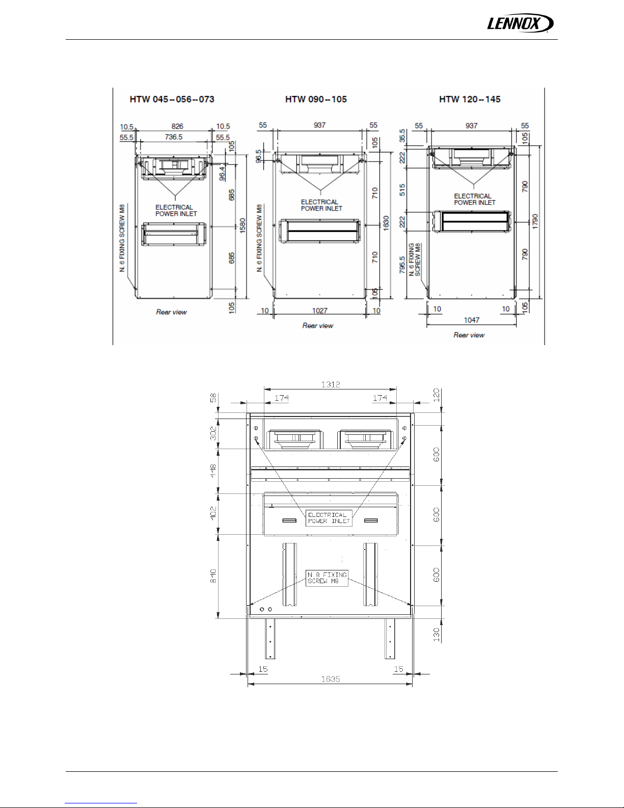
The dimensions of the air outlet/intake flanges and t he positions of the holes for the screw anchors and
power cables are shown Fig. 2:
Page 8
@DNOVA THX_R410A-IOM-1506-E 6
Fig. 2 Wall mounted unit
THX0230-290
Page 9
@DNOVA THX_R410A-IOM-1506-E 7
Page 10
@DNOVA THX_R410A-IOM-1506-E 8
3 Installation
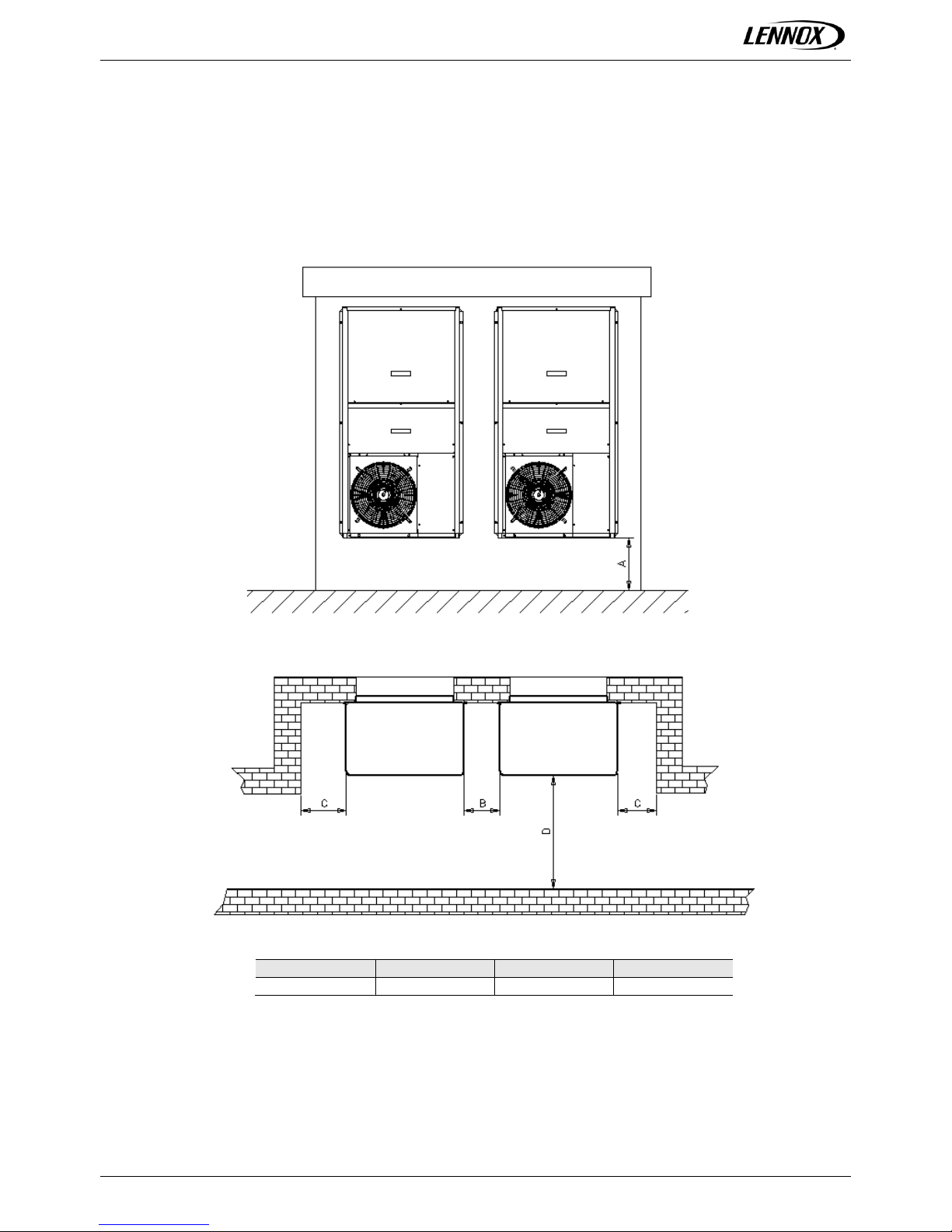
The THX/D pac kage air-conditioning uni t is suitable for all en vironments except aggr essive ones. Do not
place any obstacles near the units and make sure that the air flow is not im peded by obstacles and/or
situations causing back suction (see Fig.3).
Fig. 3 Service Area
A (mm)
B (mm)
C (mm)
D (mm)
Min. 400
Min. 200
Min. 400
Min. 2000
The following steps should be carried out to ensure proper installation (see Fig. 4):
Page 11
@DNOVA THX_R410A-IOM-1506-E 9
• Apply a vibration-damping rubber lining between the unit and wall
• Position the unit on the wall, fitting the a ir outl et and in tak e flanges correc tl y into p lace; us e M8 s cre ws
secured by suitable anchors to fasten the unit.
• carefully seal the entire perimeter of the unit on t he exterior wall of the shelter a nd the air intake and
outlet flanges on the inside.
• In order to obtain stable indoor conditions, make sure that the shelter interior is insulated from the
outside; any openings should be sealed closed
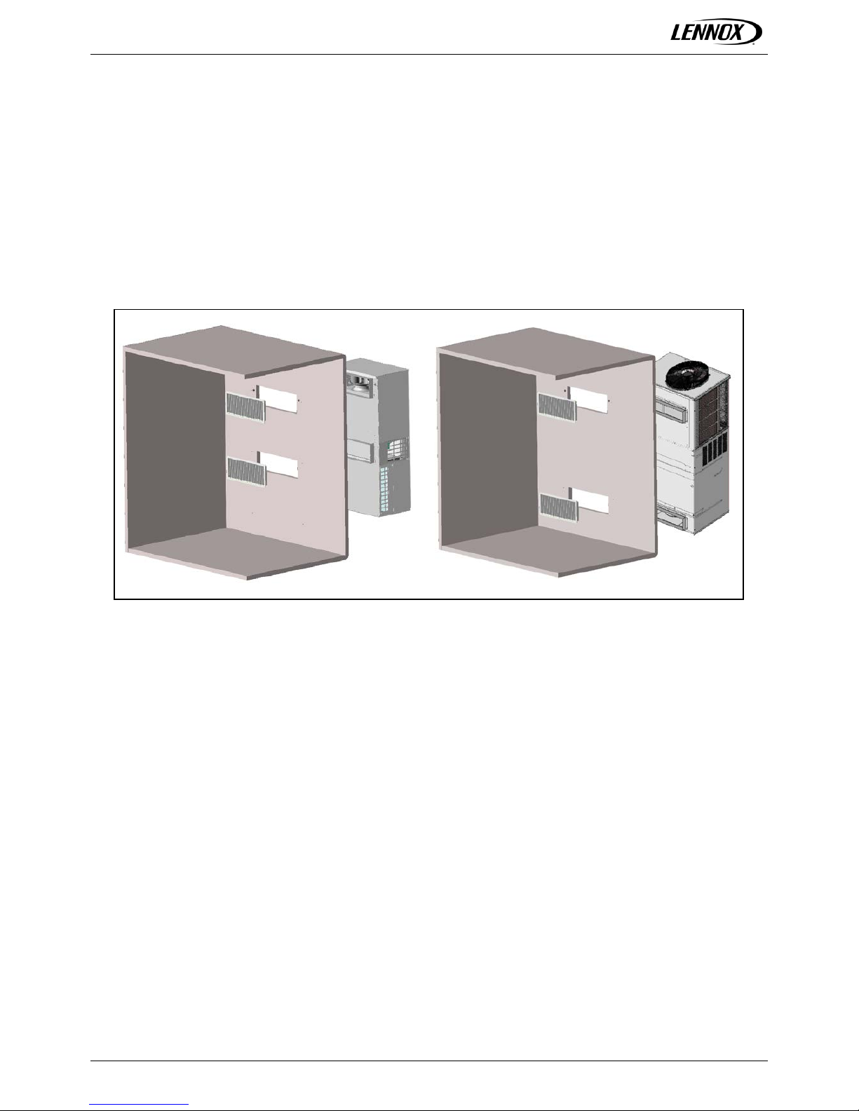
Position the air outlets (with a double row of vertical and horizontal fins) and intakes (with a single row of
horizontal fins) inside the shelter and fix them in place with self-tapping screws. Refer to the installation
drawings provided for the exact indications.
Fig. 4 Shelter installation
The recommended sizes for the power cables and emergency line are indicated in the at tached electrical
scheme.
Unità HTW Uni t à HTWD
Page 12

@DNOVA THX_R410A-IOM-1506-E 10
4 Evacuation and Charging Ope ra t ions
This type of work must be carried out by qualified personnel only trained to do their job
in accordance with current laws and regulations.
4.1 Introduction
The simultaneous presence of liquid and vapourmakes it necessary for both to be in a state of saturation
(Gibbs law), as shown
in Fig. 5. In conditions of thermal equilibrium, the pressure in the tank corresponds to the T of the
surrounding environm ent;
a withdrawal of refrigerant charge wil l caus e pr ess ur e drops , whic h wil l be assoc iated w it h:
• with drawal of refrigerant charge pressure drop in tank
• pressure drop in tank: T drop change of state
• T drop change of state: evaporation of part of the liquid, causing the liquid itself to
cool
• cooling of liquid: thermal exchange with ambient air, further evaporation of
remaining liquid;the original pressure is restored in the tank
after a certain amount of time
Fig. 5 Diagramma legge di Gibbs
4.2 Vacuum and charging machine
Vacuum cycle
In general it is preferabl e to apply a “long” rather than “hard” vacuum : reaching low pres sures too abrup tly
may in fact cause any trapped humidity to evaporate instantaneously, thereby freezing part of it.
Fig. 6 Vacuum cycle diagram
The Fig. 6 represents a vacuum cycle and an optimal subsequent pressure rise for the refrigeration devices
we manufacture. As a rule, if ther e is suspic ion of an extensi ve presenc e of hum idity throu ghout the c ircuit
or system as a whole, the vacuum must be “brok en” with anhydrous nitrogen an d then the steps must be
Page 13

@DNOVA THX_R410A-IOM-1506-E 11
repeated as described; t his operation facilitates th e removal of trapp ed and/or frozen humidit y during the
evacuation process
.
4.3 Evacuating a circuit “contaminated” with refrigerant
The first step is to r emove the refriger ant from the circ uit using a specific machine with a dr y compressor
for recovering the refr igerant. Ref rigera nts all t end to diss olve in oi l (com pr essor sump) in percenta ges that
are directly proportional t o increas es in pressur e and dec reases in the T of t he oil itself --- Charles’ Law --(see Fig. 7).
Fig. 7 Charles’ law diagram
The release of ref rigerant tends to coo l the oil and thu s ac tuall y serves to op pose the rel ease itself : for this
reason, it is advisable to switch on the crankcase heating elements, if available, during the evacuation
process. If a high % of refrigerant gets into contact with the P irani gauge (vacuum sensor) , it may “drug”
the sensitive element of the latter, rendering it inefficient for a certain period of time. For this r eason, if no
machine for recovering refrigerant is available, it is nonetheless advisable to switch on the crankcase
heating elements and a void appl ying a vacuum until the circuit has been adeq uately purged of refriger ant:
the refrigerant may in fact solubilize in the oil of the vacuum pump, undermining its performance for
a long time (hours).
4.4 Charging positions (single point)
The best position for charging the air conditioners is the section between the ther mostatic valve and the
evaporator; care should be taken to avoid fixing the th ermostat bulb until the ope ration is complete: th is is
important to ensure that the valve orifice remains open so as to allow the passage of refrigerant also
toward the condenser/receiver.
If possible, avoid th e inflow of refr igerant into the com pressor as this m ay cause excess ive dilution of the
lubricant; in any case, first check the com patibil ity between the crankcas e capac it y and the required charge
volumes.
Page 14

@DNOVA THX_R410A-IOM-1506-E 12
5 Electrical Connections
5.1 Generalities
Before carrying out any job on electrical parts, make sure the power supply is
disconnected.
Check that the mains elect ricity supply is compatible with the spec ifications (voltage, number of phases,
frequency) shown on the unit ra ting plate. The po wer connection f or single---phase loads is to be made
with a three---pole cable and “N” wire at the centre of the star (optional: power supply w/o neutral).
The size of the cable and line protections must conform to the specifications provided in
the wiring diagram.
The supply voltage m ay not under go fluc tuatio ns exc eeding ±5% and th e unbal anc e between p hases m ust
always be below
2%.
The above operating conditions must always be complied with: failure to ensure said
conditions will result in the immediate invalidation of the warranty.
The electrical connect ions must be m ade in accordance with the information s hown in the wiring diagram
provided with the unit and with current and local regulations. An earth connection is mandatory. The
installer m ust connect the earth wire us ing the earth term inal situated on the ele ctric control board ( yellow
and green wire). The power s upply to the control circu it is taken from the pow er line through an insu lating
transformer situated on the electric control board. The control circuit is protected by suitable fuses or
automatic breakers depending on the unit size.
Page 15

@DNOVA THX_R410A-IOM-1506-E 13
6 Machine Functional Schem e s
Fig. 8 Machine functional schemes
Page 16

@DNOVA THX_R410A-IOM-1506-E 14
7 Starting Up
7.1 Preliminary checks
• Check that the electrical connections have been made properly and that all the terminals are securely
tightened. This check should also be included in a periodic six-month inspection.
• Check that the voltage at the RST terminals is 400 V ± 5%and make sure the yellow indicator light of the
phase sequence relay is on. The phase sequence relay is positioned on the electric control board; if the
sequence is not duly observed, it will not enable the machine to start.
• Make sure there are no refrigerant leaks that may have been caused by accidental impacts during
transport and/or installation.
• Check the power supply to the crankcase heating elements, where present.
The heating elements must be turned on at least 12 hours before the unit is started. They
are automatically activated when the main switch is put on. Their function is to raise the T of
the oil in the sump and limit the quantity of refrigerant dissolved in it.
To verify whether the heating elements are working properly, check the lower part of the compressors: it
should be warm or in any case at a temperature 10---15 °C higher than the ambient temperature.
Fig. 9 Diagramma legge di Charles
The diagram in Fig. 9 illustrates a specific property of gases (Charles’ Law), which are more soluble in liquids
as the pressure incr eases but less soluble as the temperatur e increases: if the oil in the sump is held at a
constant pressure, an incre ase in temperature wil l significantl y reduce the am ount of refrigerant dis solved in
it, thus ensuring that the desired lubricating function is maintained.
7.2 Starting up instructions (for THX/D packaged air---conditioning units)
Electric connections and starting up
• Loosen the screws securing the cover of the electric compartment and open it.
• Introduce the power cable through the hole provided on the side of the unit (see Fig. 10) and secure it in
place with the cable holder.
Page 17

@DNOVA THX_R410A-IOM-1506-E 15
Fig. 10 Electrical cables inlet holes
Electrical power / UPS inlet
• Connect the power supply and earth wire to the terminals of the main switch.
• Put OFF switch “QF1” of the compressor so as to be sure it will not start running in the wrong direction in
the case of a phase sequence error.
• Switch on the power supply by turning the main switch (QS) to ON.
• After 60 seconds the compressor will start.
• Check the phase sequence relay situated in the middle of the electric control board to make sure the
phases are in the right sequence R---S---T; the green indicator light should go on: if it does not, disconnect
the power supply to the unit from the external distribution board, invert two phases and repeat the check.
IN NO CASE SHOULD YOU TAMPER WITH THE WIRING DOWNSTREAM FROM THE MAIN SWITCH
since this may alter the correct sequence of other devices.
• Check that there are no leaks on the refrigerant side.
• Put the compressor switch “QF1” back on.
• Close the electric compartment by replacing the cover.
Usage
• Always consult the USER manual and control system manual provided with the unit when under taking
maintenance and/or advanced Set-Up.
7.3 Starting operation
Before starting the unit, tur n the main switch on, sele ct the operating m ode desired from the control panel
and press the ”ON” button on the control panel.
If the unit fails to start up, check if the service thermostat has been set according to the nominal
values provided.
You should not disconnect the unit from the power supply during periods when it is
inoperative but only when it is to be taken out of service for a prolonged period (e.g. at the
end of the season). To turn off the unit temporarily follow the directions provided in the
section 4.5.
Checks during operation
Page 18

@DNOVA THX_R410A-IOM-1506-E 16
• Check the phas e sequence relay on the control board to verify whether the ph ases occur in the correct
sequence: if they do not, disconnect the unit from power supply and invert two phases of the inc oming
three-pole cable.
Never attempt to modify internal electrical connections: any undue modifications will immediately
invalidate the warranty.
Checking the refrigerant level
• After a few hours of operati on, chec k wh ether t he liqu id le vel ind icator has a gree n ring: a yellow color
indicates the pr esence of humidity in the circuit. In such a case the cir cuit must be dehumidified by
qualified personnel.
• Large quantities of bubbles should n ot appear thr ough the liquid le vel indic ator . A constant pas sage of
numerous bubbles may indicate that the refrigerant level is low and needs to be topped up.
• Make sure the overheating of the cooling fluid is limited to between 5 and 8 °C: to this end:
1 ) read the temperature indicated by a contact thermometer placed on the compressor intake
pipe;
2 ) read the temperature indicated on the scale of a pressure gauge likewise connected to the
intake side; refer to t he pressure gaug e scale f or the ref rigerant R410A.The degree of overheati ng
is given by the difference between the temperatures thus determined.
• Make sure that the Sub-cooling of the cooling fluid is limited to between 3 and 5°C: to this end:
1 ) read the temperature indicated by a contact thermometer placed on the condenser outlet pipe;
2 ) read th e tem peratur e in dicated on the sc ale of a pres sure gau ge con necte d to the l iquid inlet at
the condenser outlet ; refer to the press ure ga uge scal e for the ref rigerant R410A, The degre e of Subcooling is given by the difference between the temperatures thus determined.
Warning: all THX/D units are charged with R410A. Any top-ups must be made using
the same type of refrigerant. This operation is to be considered extraordinary
maintenance work and must be performed by qualified personnel only.
Warning: the refrigerant R410A requires “POE” polyolester oil of the type and
viscosity indicated on the compressor rating plate. For no reason should oil of a
different type be introduced into the oil circuit.
Page 19

@DNOVA THX_R410A-IOM-1506-E 17
8 Setting Operating Parameters
8.1 Generalities
All the control devices are set and tested in the factory before the unit is dispatched. However, after the unit
has been in service for a reasonable period of time you can perform a check on the operating and s afety
devices. The settings are shown in Tab. 3 and Tab. 4.
All servicing of the equipment is to be considered extraordinary maintenance and may
be carried out BY QUALIFIED TECHNICIANS ONLY: incorrect settings may cause
serious damage to the unit and injuries to persons .
The operating parameters and control system settings configurable by means of the microprocessor control
are password protected if they have a potential impact on the integrity of the unit.
Tab. 3 Setting of control devices
Control device
Set point
Differential
Differential air pressure switch (outlet air flow)
Pa
50
30
Differential air pressure switch (dirty filter)
Pa
50
20
Tab. 4 Setting of control devices
Control device
Activation
Differential
Resetting
Maximum pressure switch
Bars-r
42.0 4 Manual
Minimum pressure switch
Bars-r
1.5
1.5
Automatic
Modulating condensation control devi ce
Bars-r
20
6.5
Time lapse between two compressor starts
s
300 - -
8.2 Maximum pressure switch
The high pressure switch stops the compressor when the outlet pressure exceeds the set value.
Warning: do not attempt to change the setting of the maximum pressure switch: Should the
latter fail to trip in the event of a pressure increase, the pressure relief valve will open.
The high pressure switch must be manually reset; t his is possible only when th e pressure falls below the
set differential (see Tab. 4).
8.3 Minimum pressure switch
The low pressure switch stops the compressor when the inlet pressure falls below the set va lue for more
than 1 seconds. T he switch is autom atically reset when the pressure rises abov e the set differential (see
Tab. 4).9
Page 20

@DNOVA THX_R410A-IOM-1506-E 18
9 Maintenance
The only operations to be p erf ormed b y the us er ar e to switc h the unit On and Of f. All other operat ions are
to be considered maint enance work and m ust thus be carried o ut by qua lified personnel tra ined to do t heir
job in accordance with current laws and regulations.
9.1 Warnings
All the operations described in this chapter MUST ALWAYS BE PERFORMED BY
QUALIFIED PERSONNEL ONLY ..
Before carrying out any work on the unit or accessing internal parts, make sure you
have disconnected it from the mains electricity supply.
The upper part and the outlet pipe of the compressor reach high temperatures. Be
especially careful when working in the surrounding area with the panels off.
Be especially careful when working in proximi ty to finned coils since the 0.11 mm thick
aluminum fins can cause superficial injuries due to cuts.
After completing maintenance jobs, always replace the panels enclosing the units and
secure them while fastening screws provided.
9.2 Generalities
To guarantee a constantly satisfactory performance over time, it is advisable to carry out routine
maintenance and check s as described in Tab. 5. T he indications below are related to standard tear a nd
wear.
Tab. 5 Routine maintenance
Operation
Frequency
Check the efficiency of all the control and safety devices. Once a year
Check the terminals on the electric control board and compressor terminal boards to
ensure that they are securely tightened. The movable and fixed contacts of the circuit
breakers must be periodically cleaned and replaced whenever they show signs of
deterioration
Once a year
Check the refrigerant level by means of the liquid level indicator Every 6 mos.
Check the efficiency of the differential air pressure switch and dirty filter differential
pressure switch
Every 6 mos.
Check the condition of the air filter and replace it if necessary Every 6 mos.
Check the humidity indicator (green=dry, yellow=humid) on the liquid level indicator; if the
indicator is not green as shown on the indicator sticker, replace the filter
Every 6 mos.
Page 21

@DNOVA THX_R410A-IOM-1506-E 19
9.3 General inspection
9.4 Inspecting the air filter (THX)
Page 22

@DNOVA THX_R410A-IOM-1506-E 20
9.5 Inspecting the air filter (THXD)
Page 23

@DNOVA THX_R410A-IOM-1506-E 21
9.6 Inspecting the damper/motor (THXD)
Page 24

@DNOVA THX_R410A-IOM-1506-E 22
9.7 Inspecting the damper/motor (THX)
9.8 Fixing of cables
Page 25

@DNOVA THX_R410A-IOM-1506-E 23
9.9 Inspection of the compressor section
9.10 Inspection the sight glass and the filter drier
Page 26

@DNOVA THX_R410A-IOM-1506-E 24
9.11 Repairi ng the cooling circuit
Warning: while performing repairs on the cooling circuit or maintenance work on the
compressors, make sure the circuit is left open for as little time as possible. Even if
briefly exposed to air, ester oils tend to absorb large amounts of humidity, which results
in the formation of weak acids.
If the cooling circuit has undergone any repairs, the following operations must be carried out:
• tightness test;
• evacuation and drying of the cooling circuit;
• charging with refrigerant.
If the system has to be drained, always recover the refrigerant present in the circuit using
suitable equipment; the refrigerant sh ou ld be handled exclusively in the liquid phase.
9.12 Tightness test
Fill the circuit with anhydrous nitrogen supplied from a tank with a pressure---reducing valve until the
pressure rises to 22 bars.
During the pressurization ph ase, do no t exce ed a pressu re of 2 2 bars o n th e compr esso r
low pressure side
.
The presence of any leak s m ust be determ ined usi ng s pecial le ak detec tors . Should an y leak s be detec ted
during the test, empty out the circuit before repairing the leaks with suitable alloys.
Do not use oxygen in the place of nitrogen as a test agent, since this would cause a risk
of explosion.
9.13 Hard vacuum and drying of cooling circuit
To achieve a hard vacuum in th e coo ling circ uit it is nec essar y to use a pum p c apable of gener ating a high
degree of vacuum, i.e. 15 0 Pa of absolute pressure with a capacit y of approx imately 10 m3/h. If such a
pump is available, one e vacuation will nor mally suff ice to achieve an abs olute pres sure of 150 Pa. If there
is no such vacuum pump available, or whenever the circuit has remained open for long periods of time, you
are strongly recomm ended to ado pt th e triple e vacuati on method. This method is also recom m ended when
there is a presence of humidity within the circuit.
The vacuum pump should be connected to the inlets.
The procedure to be carried out is as follows:
• Evacuate the circuit until you reach an absolute pressure of at least 350 Pa: at this point inject
nitrogen into the circuit until you reach a relative pressure of about 1 bar.
• Repeat the step described above.
• Carry out the step described above for the third time, but in this case attempting to reach the hardest
vacuum possible.
Using this procedure you can easily remove up to 99% of pollutants.
Page 27

@DNOVA THX_R410A-IOM-1506-E 25
9.14 Recharging with refrigerant R410A
• Connect the tank of refrigerant gas to the male 1/4 SAE inlet situated on the liquid line after
discharging a little gas to eliminate air in the connection pipe.
• Fill with refrigerant in liquid form until you reach 75% of the total charge.
• T hen c onnect to the inlet on the pipe bet wee n t h e ther mostatic valve and evapor a tor and complete the
charging process with the refrigerant in liquid form until no more bubbles can b e seen on the liquid
level indicator and the operating parameters specified in section 4.4 have been reached.
Introduce refrigerant through the inlet in the liquid line.
A unit that was originally charged with R410A in the factory must not be charged with
other refrigerants without the written authorization of Lennox.
9.15 Environmental protec ti on
The law implementing the regulations (reg. EEC 2037/00) which govern the use of ozone---depleting
substances and gr eenhous e gases bans th e disp ersal of refr igerant gas es in th e envir onm ent and requir es
whoever is in their poss ession to recover them and, at the end of their usef ul life, either to return t hem to
the dealer or take them to a suitable waste disposal facility.
The refrigerant HFC R410A is not harmful to the ozone layer but is included among the substances
responsible for the greenhouse effect and thus falls within the scope of the aforesaid regulations.
Therefore, special care should be taken when carrying out maintenance work to minimize
refrigerant leaks.
Page 28

@DNOVA THX_R410A-IOM-1506-E 26
10 Troubleshooting
On the next pages you will f ind a list of the most common causes that may cause the package un it to f ail or
malfunction. These causes are broken down according to easily identifiable symptoms.
You should be extremely careful when attempting to i mplement any of the possible
remedies suggested: overconfidence can result in injuries, even serious ones, to
inexpert individuals. Therefore, once the cause has been identified, you are advised to
contact the manufacturer or a quali fied technician for help.
FAULT
POSSIBLE CAUSES
CORRECTIVE ACTIONS
The unit does not start
No power supply
Check that power is being supplied both to t he primary
and auxiliary circuits
The electronic card is cut off from
the power supply
Check the fuses
Alarms have been triggered
Check whether any alarms are signalled o n the
microprocessor control panel, eli m inate the causes
and restart the uni t
The phase sequence i s wrong
Invert two phases i n the primary power line after
disconnecting t hem upstream from the unit
The compressor is noisy
The compressor i s rotating in the
wrong direction
Check the phase seque nce relay. Invert the phases on
the terminal board af ter disconnecting the unit and
contact the manufacturer
Presence of abnormally high
pressure
Insufficient flow of air to the
condenser
Check for the presence of obstructions in the
condenser sect ion ventilation circuit
Check whether the condenser coil surface is
obstructed
Check the condensation control device (optional)
Presence of air i n the refrigerant
circuit, as revealed by the presence
of bubbles in the flow indicator also
with undercooling v alues exceeding
5 °C
Drain and pressurise the circuit and check for leaks.
Evacuate slowly (for more than 3 hours) until reaching
a pressure of 0.1 Pa and then recharge in the liquid
phase
Unit overcharged, as revealed by
an Sub-cooling of mor e than 8 °C
Drain the circui t
Thermostatic valve and/or filter
obstructed. These symptoms may
also occur in the pr esence of an
abnormally low pressure
Check the temperatures upstream and downstream
from the valve and filter and replace them if necessary
Low condensation pressure Transducer fault
Check the effici ency of the condensati on control
device (optional)
Low evaporation pressure
Malfunctioning of thermostatic
valve
Warming the bulb wi th your hand, check whet her the
valve opens and adjust it if necessary. If it does not
respond, replace it
Filter dryer clogged
Pressure drops upstream and downstream from the
filter should not exceed 2°C. If they do, replace the
filter
Low condensation T
Check the effici ency of the condensation control
device (where present)
Low level of refr igerant
Check the refrigerant level by measuring the degree of
Sub-cooling; if i t is below 2°C replenish the charge
The internal thermal protection
device has tripped
In the case of compressors equipped with a protection
module, check the thermal contact. Identify the causes
after restarting
The compressor does not
start
The circuit break ers or line fuses
have been tripped by a short circuit
Pinpoint the cause by measuring the resistance of the
individual windings and the insulation from the casing
before restoring pow er
One of the high or low pressure
switches has tri pped
Check on the micr oprocessor, eliminate the causes
The phases have been inverted in
the distribution compartment
Check the phase seque nce relay
Page 29

@DNOVA THX_R410A-IOM-1506-E 27
11 Dimensional drawing
MOD. THX 0451 - 0561 - 0731
FRONT
VIEW
SIDE
VIEW
TOP
VIEW
Page 30

@DNOVA THX_R410A-IOM-1506-E 28
MOD. THX 0901 - 1051
FRONT VIE W
SIDE VIEW
TOP VIEW
Page 31

@DNOVA THX_R410A-IOM-1506-E 29
MOD. THX 1201 - 1451
FRONT VIEW
SIDE VIEW
TOP VIEW
Page 32

@DNOVA THX_R410A-IOM-1506-E 30
MOD. THX 0902 – 1102 - 1302
FRONT VIE W
SIDE VIEW
TOP VIEW
MOD. THX 2302 - 2902
Page 33

@DNOVA THX_R410A-IOM-1506-E 31
Page 34

@DNOVA THX_R410A-IOM-1506-E 32
MOD. THXD 0451 – 0561 - 0731
FRONT VIE W
SIDE VIEW
TOP VIEW
Page 35

@DNOVA THX_R410A-IOM-1506-E 33
MOD. THX 0901 – 1051 – 1201 - 1451
FRONT VIEW
SIDE VIEW
TOP VIEW
Page 36

+ 32 3 633 3045 +351 229 066 050
+33 1 64 76 23 23 +7 495 626 56 53
+49 (0) 211 950 79 600 +34 915 401 810
+ 39 02 495 26 200 +38 044 585 59 10
+ 31 332 471 800 +44 1604 669 100
+48 22 58 48 610
LENNOX DISTRIBUTION
+33 4 72 23 20 20
+ 32 3 633 3045 +351 229 066 050
+33 1 64 76 23 23 +7 495 626 56 53
+49 (0) 211 950 79 60 +34 915 401 810
+ 39 02 495 26 200 +38 044 585 59 10
+ 31 332 471 800 +44 1604 669 100
+48 22 58 48 610
LENNOX DISTRIBUTION
+33 4 72 23 20 20
www.lennoxemea.com
ADNOVA-THX_R410A-
IOM-1506-E
Due to LENNOX EMEA ongoing commitment to quality, the specifi cations, ratings and
dimensions are subject to change without notice and without incurring liability.
Improper installation, adjustment, alteration, service or maintenance can cause property
damage or personal injury.
Installation and service must be performed by a qualifi ed installer and servicing agency.
SALES OFFICES :
BELGIUM AND LUXEMBOURG PORTUGAL
FRANCE RUSSIA
GERMANY SPAIN
ITALY UKRAINE
NETHERLANDS UNITED KINGDOM AND IRELAND
POLAND
OTHER COUNTRIES :
 Loading...