

Lennox T?CLASS TPA024S4, T?CLASS TPA036S4, T?CLASS TPA048S4, T?CLASS TPA060S4 Unit Information
Page 1
Service Literature
Corp. 0923−L10
01−2010
T−CLASSt
TPA*S4
M and T Voltages
TPA*S4 M and T Voltage
WARNING
Improper installation, adjustment, alteration, service or
maintenance can cause personal injury, loss of life, or
damage to property.
Installation and service must be performed by a licensed
professional installer (or equivalent) or a service agency.
IMPORTANT
The Clean Air Act of 1990 bans the intentional venting of
refrigerant (CFCs, HCFCs AND HFCs) as of July 1,
1992. Approved methods of recovery, recycling or
reclaiming must be followed. Fines and/or incarceration
may be levied for noncompliance.
Units
TABLE OF CONTENTS
Specifications and Electrical Data 2. . . . . . . . . . . . . . . . . .
Unit Dimensions 2. . . . . . . . . . . . . . . . . . . . . . . . . . . . . . . . .
Typical Control Panel Parts Arrangement 4. . . . . . . . . . .
Typical Unit Parts Arrangement 5. . . . . . . . . . . . . . . . . . .
Model Number Identification 5. . . . . . . . . . . . . . . . . . . . . .
Unit Components 6. . . . . . . . . . . . . . . . . . . . . . . . . . . . . . . .
General Information 8. . . . . . . . . . . . . . . . . . . . . . . . . . . . .
Operating Gauge Set and Service Valves 8. . . . . . . . . . .
Recovering Refrigerant from Existing System 10. . . . . .
Unit Placement 11. . . . . . . . . . . . . . . . . . . . . . . . . . . . . . . . .
New or Replacement Line Set 12. . . . . . . . . . . . . . . . . . . .
Metering Devices and Flushing the System 15. . . . . . . .
Testing for Leaks 16. . . . . . . . . . . . . . . . . . . . . . . . . . . . . . .
Evacuating the System 17. . . . . . . . . . . . . . . . . . . . . . . . . .
Electrical Connections 18. . . . . . . . . . . . . . . . . . . . . . . . . .
Servicing Unit Void of Charge 20. . . . . . . . . . . . . . . . . . . .
Unit Start−Up 20. . . . . . . . . . . . . . . . . . . . . . . . . . . . . . . . . . .
System Refrigerant 20. . . . . . . . . . . . . . . . . . . . . . . . . . . . .
System Operation 24. . . . . . . . . . . . . . . . . . . . . . . . . . . . . .
Defrost System 24. . . . . . . . . . . . . . . . . . . . . . . . . . . . . . . .
Maintenance 24. . . . . . . . . . . . . . . . . . . . . . . . . . . . . . . . . . .
Start−Up and Performance Checklist 28. . . . . . . . . . . . . .
Wiring Diagrams and Sequence of Operations 29. . . . .
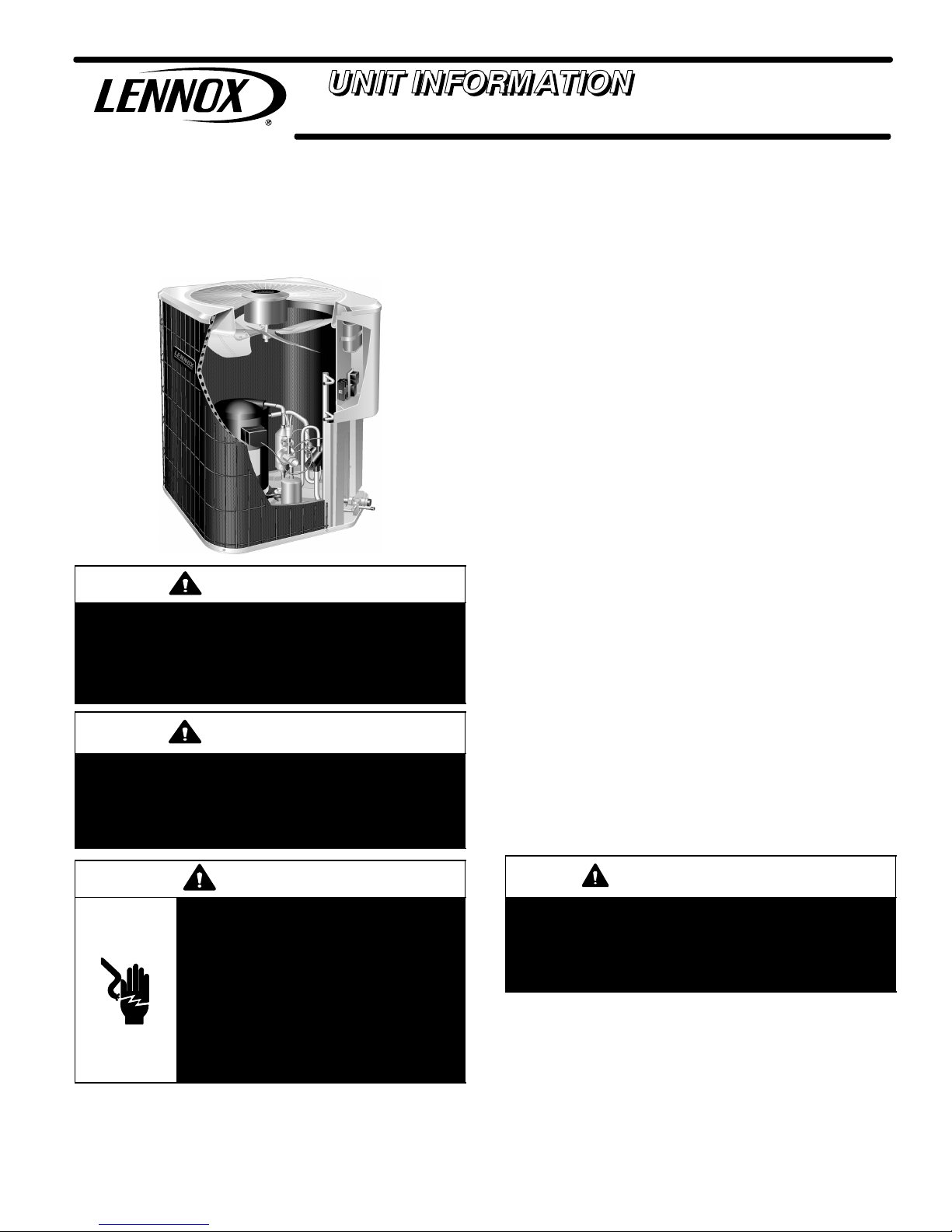
The TPA*S4 is a commercial split-system heat pump. All
major components (indoor blower and coil) must be
matched according to Lennox recommendations for the
compressor to be covered under warranty. Refer to the
Engineering Handbook for approved system matchups.
WARNING
Electric Shock Hazard. Can cause injury
or death. Unit must be grounded in
accordance with national and local
codes.
Line voltage is present at all components
when unit is not in operation on units with
single-pole contactors. Disconnect all
remote electric power supplies before
opening access panel. Unit may have
multiple power supplies.
IMPORTANT
This model is designed for use in expansion valve
systems only. An indoor check expansion valve
approved for use with HFC−410A refrigerant must be
ordered separately, and installed prior to operating the
system.
This instruction is specifically for the following model
voltage configurations:
S M Voltage 380/420VAC, 3−Phase, 50 Hertz
S T Voltage 220/240VAC, 1−Phase, 50 Hertz
Page 1
Page 2

Specifications and Electrical Data1
SPECIFICATIONS − SINGLE PHASE
General
Data
Model No. TPA024S4 TPA036S4 TPA048S4
Nominal kW 7 10.5 14.0
Connections
(sweat)
Liquid line o.d. − in. 3/8 3/8 3/8
Vapor line o.d. − in. 3/4 7/8 7/8
1
Refrigerant (R−410A) furnished 2.95 kg (6 lbs. 8 oz.) 2.86 kg (6 lbs. 5 oz.) 5.30 kg (11 lbs. 11 oz.)
Outdoor
Coil
Net face area
2
m
(sq. ft.)
Outer coil 1.41 (15.21) 1.41 (15.21) 1.96 (21.11)
Inner coil − − − 1.44 (15.50) 1.98 (21.31)
Tube diameter − in. 5/16 5/16 5/16
Number of rows 1 2 2
Fins per meter (inch) 866 (22) 866 (22) 866 (22)
Outdoor
Fan
Diameter − mm (in.) 457 (18) 457 (18) 559 (22)
Number of blades 3 4 4
Motor W (hp) 149 (1/5) 149 (1/5) 248 (1/3)
L/s (Cfm) 945 (2000) 965 (2042) 1530 (3242)
Rev / min 942 917 904
Watts 138 158 313
Shipping Data − kg (lbs.) 1 package 64 (140) 82 (180) 113 (250)
Electrical Data
Line voltage data − 50 hz − 1ph 220 / 240V 220 / 240V 220 / 240V
2
Maximum overcurrent protection (amps) 25 35 35
3
Minimum circuit ampacity 14.7 21.1 21.6
Compressor Rated load amps 10.9 16.0 15.9
Locked rotor amps 60.0 87.0 98.0
Outdoor
Fan Motor
Locked rotor amps 1.9 1.9 4.1
NOTE − Extremes of operating range are plus 10% and minus 5% of line voltage.
1
Refrigerant charge sufficient for 4.6 m (15 ft.) length of refrigerant lines.
2
Heating Air Conditioning and Refrigeration type circuit breaker or fuse.
3
Refer to local codes to determine wire, fuse and disconnect size requirements.
Power factor 1.1 1.1 1.7
Full load amps 2.0 2.0 4.1
Page 2
Page 3

SPECIFICATIONS − THREE PHASE
General
Data
Model No. TPA036S4 TPA048S4 TPA060S4
Nominal kW 10.5 14.0 17.6
Connections
(sweat)
Liquid line o.d. − in. 3/8 3/8 3/8
Vapor line o.d. − in. 7/8 7/8 1−1/8
1
Refrigerant (R−410A) furnished 2.86 (6 lbs. 5 oz.) 5.30 (11 lbs. 11 oz.) 6.24 (13 lbs. 12 oz.)
Outdoor
Coil
Net face area
2
m
(sq. ft.)
Outer coil 1.41 (15.21) 1.96 (21.11) 2.28 (24.50)
Inner coil 1.44 (15.50) 1.98 (21.31) 2.19 (23.56)
Tube diameter − in. 5/16 5/16 5/16
Number of rows 2 2 2
Fins per meter (inch) 866 (22) 866 (22) 866 (22)
Outdoor
Fan
Diameter − mm (in.) 457 (18) 559 (22) 559 (22)
Number of blades 4 4 4
Motor W (hp) 125 (1/6) 250 (1/3) 185 (1/4)
L/s (Cfm) 965 (2042) 1530 (3242) 1505 (3192)
Rev / min 917 904 692
Watts 158 313 275
Shipping Data − kg (lbs.) 1 package 82 (180) 113 (250) 116 (255)
Electrical Data
Line voltage data − 50 hz − 3ph 380 / 420V 380 / 420V 380 / 420V
2
Maximum overcurrent protection (amps) 10 10 15
3
Minimum circuit ampacity 8.0 8.6 10.7
Compressor Rated load amps 6.0 6.1 7.8
Locked rotor amps 46.0 43.0 51.5
Power factor 0.55 1.0 1.0
Outdoor
Fan Motor
Full load amps 1.1 2.2 2.3
Locked rotor amps 1.9 4.1 3.1
NOTE − Extremes of operating range are plus 10% and minus 5% of line voltage.
1
Refrigerant charge sufficient for 4.6 m (15 ft.) length of refrigerant lines.
2
Heating Air Conditioning and Refrigeration type circuit breaker or fuse.
3
Refer to local codes to determine wire, fuse and disconnect size requirements.
OPTIONAL ACCESSORIES
For update−to−date information, see any of the following publications:
S Lennox TPA*S4 Engineering Handbook
S Lennox Commercial Price Book
Page 3
Page 4

Unit Dimensions − inches (mm)2
A
Outdoor Coil Fan
Compressor
A
Discharge Air
BC
Electrical
Inlets
2 (51)
SIDE VIEW
Model No. A B C
TPA024S4N41T 24−1/4 (616) 33−1/4 (845) 32−1/2 (826)
TPA036S4N41M 24−1/4 (616) 33−1/4 (845) 32−1/2 (826)
TPA036S4N41T 28-1/4 (718) 37 (940) 36−1/4 (921)
TPA048S4N41M 28-1/4 (718) 37 (940) 36−1/4 (921)
TPA048S4N41T 28-1/4 (718) 37 (940) 36−1/4 (921)
TPA060S4N41M 28-1/4 (718) 43−1/4 (1099) 42−1/2 (1080)
3/4 (19)
Vapor and Liquid
Line Connections
2-3/4 (70)
Optional Unit
Stand-off Kit (4)
(Field−installed)
SIDE VIEW
Typical Control Panel Parts Arrangement3
CAPACITOR
GROUND LUG
CONTACTOR LOCATION
OR
THREE
PHASE
ONE
PHASE
CUTOUT FOR HIGH
VOLTAGE CONDUIT
CONTROL
DEFROST CONTROL BOARD
CONTROL WIRE LOOP
Page 4
Page 5

Typical Unit Parts Arrangement4
NOTE: PLUMBING LAYOUT MAY VARY SLIGHTLY BETWEEN MODEL SIZES.
COMPRESSOR
HARNESS
DEFROST
THERMOSTAT
COMPRESS0R
DISCHARGE LINE
MUFFLER
CHECK EXPANSION
BI−FLOW FILTER DRIER
VALV E
EQUALIZER LINE
TRUE SUCTION PORT
HIGH PRESSURE SWITCH (S4)
LIQUID LINE SERVICE VALVE
LOW PRESSURE SWITCH
REVERSING VALVE
REVERSING VALVE SOLENOID
VAPOR LINE SERVICE VALVE
Model Number Identification5
Brand/Family
T = T−Classt Product Line
Unit Type
P = Split−System Heat Pump
Major Design Sequence
A = 1st Generation
B = 2nd Generation
TPA M1036 S 44 N
024 = 2 Ton
030 = 2.5 Tons
0036 = 3 Tons
048 = 4 Tons
060 = 5Tons
Cooling Efficiency
S = Standard Efficiency
Page 5
Voltage
M = 380/420V−3 phase 50hz
T = 220/240V−1 phase 50hz
Minor Design Sequence
1 = 1st Revision
2 = 2nd Revision
3 = 3rd Revision
Coil Type
4 = Four−sided
Part Load Capability
N = No part load, single stage compressor
Refrigerant Type
4 = R−410A
Page 6

Information contained in this manual is intended for use by
qualified service technicians only. All specifications are
subject to change. T hi s m anual is divided into sections
which discuss the major components, refrigerant
system, charging procedure, maintenance and
operation sequence.
Remove (7) screws
FAN GUARD
FAN
IMPORTANT
This unit must be matched with an indoor coil as specified in Lennox Engineering Handbook. Coils previously charged with HCFC−22 must be flushed.
Unit Components6
CONTROL BOX
TPA*S4 units are not equipped with a 24V transformer. All
24 VAC controls are powered by the indoor unit. Refer to
wiring diagram.
Electrical openings are provided under the control box
cover. Field thermostat wiring is made to color-coded
pigtail connections.
COMPRESSOR CONTACTOR K1
The compressor is energized by a contactor located in the
control box as illustrated on Page 4. One or three−pole
contactors are used in this model. K1 is energized by the
indoor thermostat terminal Y1 (24V) when thermostat
demand is present.
CONDENSER FAN MOTOR B4 AND CAPACITOR C1
This model use a one−phase PSC fan motors which require a
run capacitor C1 located in the control box. Ratings for
C1 will be on fan motor nameplate. In all units, the
condenser fan is controlled by the compressor
contactor.
ELECTRICAL DATA tables in this manual show
specifications for condenser fans used in this model.
Remove (4) nuts
MOTOR
RACEWAY
REMOVE (7) SCREWS
SECURING FAN GUARD.
REMOVE FAN GUARD/FAN AS-
SEMBLY.
WIRING
Figure 1. Condenser Fan Motor and Compressor
Access
ALIGN FAN HUB FLUSH WITH END OF SHAFT
Figure 2. Fan Hub Alignment.
HIGH PRESSURE SWITCH S4
The manual−reset high pressure switch is located in the
liquid line. When liquid line pressure exceeds the factory
setting of 590 + 10 psi, the switch opens and shuts off the
compressor.
LOSS OF CHARGE SWITCH S24 (FIELD
INSTALLED OPTION)
The loss of charge switch is N.C. auto re−set and located
on the liquid line of the compressor. The switch opens
when liquid line pressure drops to 25 + 5 psig and shuts off
the compressor. The switch closes on a pressure rise at 55
+ 5 psig. The settings are factory set and cannot be
adjusted.
Access to the condenser fan motor on all units is gained
by removing the seven screws securing the fan
assembly as illustrated in Figure 1. The condenser fan
motor is removed from the fan guard by removing the
four nuts found on the top panel. Drip loops should be
used in wiring when servicing motor. See Figure 1 if
condenser fan motor replacement is necessary.
CRANKCASE HEATER HR1 AND OPTIONAL
THERMOSTAT S40
Crankcase heater HR1 prevents liquid from accumulating
in the compressor. HR1 is controlled by optional crankcase
heater thermostat S40, located on the liquid line. When
liquid line temperature drops below 50° F, S40 closes
energizing HR1. S40 opens when liquid line temperature
reaches 70°.
Page 6
Page 7

SUCTION
DETAIL A
SUCTION
INTERMEDIATE PRESSURE
GAS
ORBITING SCROLL
STATIONARY SCROLL
SUCTION
POCKET
SUCTION
DETAIL C
HIGH PRESSURE GAS
FLANKS SEALED
BY CENTRIFUGAL
MOVEMENT OF ORBIT
Figure 3. Scroll Compressors
REVERSING VALVE L1 AND SOLENOID
A refrigerant reversing valve with electromechanical
solenoid is used to reverse refrigerant flow during unit
operation. The reversing valve requires no
maintenance. The only replaceable part is the solenoid.
If the reversing valve itself has failed, it must be
replaced.
FORCE
DETAIL D
DISCHARGE
CRESCENT
SHAPED
GAS POCKET
DETAIL B
SUCTION
DISCHARGE
POCKET
If replacement is necessary, access reversing valve by
removing the outdoor fan motor. Refer to figure 1.
BI−FLOW DRIER
A filter drier designed for all TPA4*S4 model units is
located in the liquid line. The field installed drier is designed
to remove moisture, which can lead to compressor failure.
Any time unit is exposed to open air due to service,
drier must be replaced. All replacement driers must be
approved for HFC−410A refrigerant.
COMPRESSOR
All TPA*S4 units utilize a scroll compressor. The scroll
compressor design is simple, efficient and requires few
moving parts. A cutaway diagram of the scroll compressor is
illustrated in Figure 4. The scrolls are located in the top of the
compressor can and the motor is located just below. The oil
level is immediately below the motor.
The scroll is a simple compression concept centered around
the unique spiral shape of the scroll and its inherent
properties. Two identical scrolls are mated together forming
concentric spiral shapes as illustrated in Figure 5. One scroll
remains stationary, while the other is allowed to orbit. Note
that the orbiting scroll does not rotate or turn but merely orbits
the stationary scroll.
NOTE − During operation, the head of a scroll compressor
may be hot since it is in constant contact with discharge gas.
SUCTION
Figure 4. Scroll Compressor
DISCHARGE
DISCHARGE
PRESSURE
TIPS SEALED BY
DISCHARGE PRESSURE
Figure 5. Scroll Cross−Section
STATIONARY SCROLL
SUCTION
ORBITING SCROLL
Page 7
Page 8

The counterclockwise orbiting scroll draws gas into the outer
crescent shaped gas pocket created by the two scrolls as
illustrated in Figure 3, detail A. The centrifugal action of the
orbiting scroll seals off the flanks of the scrolls as illustrate din
Figure 3, detail B. As the orbiting motion continues, the gas is
forced toward the center of the scroll and the gas pocket
becomes compressed as illustrated in Figure 3, detail C.
When the compressed gas reaches the center, it is
discharged vertically into a chamber and discharge port in the
top of the compressor as illustrate in Figure 5. The discharge
pressure forcing down on the top scroll helps seal off the
upper and lower edges (tips) of the scrolls as illustrated in
Figure 5. During a single orbit, several pockets of gas are
compressed simultaneously providing smooth continuous
compression.
IMPORTANT
Only use Allen wrenches of sufficient hardness (50Rc −
Rockwell Harness Scale minimum). Fully insert the
wrench into the valve stem recess.
Service valve stems are factory−torqued (from 9 ft−lbs for
small valves, to 25 ft−lbs for large valves) to prevent
refrigerant loss during shipping and handling. Using an
Allen wrench rated at less than 50Rc risks rounding or
breaking off the wrench, or stripping the valve stem
recess.
See the Lennox Service and Application Notes #C−08−1
for further details and information.
The scroll compressor is tolerant to the effects of liquid
return. If liquid enters the scrolls, the orbiting scroll is allowed
to separate from the stationary scroll. The liquid is worked
toward the center of the scroll and is discharged. If the
compressor is replaced, conventional Lennox cleanup
practices must be used.
Due to its efficiency, the scroll compressor is capable of
drawing a much deeper vacuum than reciprocating
compressors. Deep vacuum operation can cause
internal fusite arcing resulting in damaged internal parts
and will result in compressor failure. Never use a scroll
compressor for evacuating or to pump system into a
vacuum. This type of damage can be detected and will
result in denial of warranty claims.
The scroll compressor is quieter than a reciprocating
compressor, however, the two compressors have much
different sound characteristics. The sounds made by a scroll
compressor do not affect system reliability, performance, or
indicate damage.
See compressor nameplate or ELECTRICAL DATA for
compressor specifications.
General Information7
These instructions are intended as a general guide and do
not supersede local codes in any way. Consult authorities
who have jurisdiction before installation.
Operating Gauge Set and Service Valves8
These instructions are intended as a general guide and do
not supersede local codes in any way. Consult authorities
who have jurisdiction before installation.
TORQUE REQUIREMENTS
When servicing or repairing heating, ventilating, and air
conditioning components, ensure the fasteners are
appropriately tightened. Table 1 lists torque values for
fasteners.
IMPORTANT
To prevent stripping of the various caps used, the
appropriately sized wrench should be used and fitted
snugly over the cap before tightening.
When servicing or repairing HVAC components, ensure
the fasteners are appropriately tightened. Table 1 provides
torque values for fasteners.
Table 1. Torque Requirements
Parts Recommended Torque
Service valve cap 8 ft.− lb. 11 NM
Sheet metal screws 16 in.− lb. 2 NM
Machine screws #10 28 in.− lb. 3 NM
Compressor bolts 90 in.− lb. 10 NM
Gauge port seal cap 8 ft.− lb. 11 NM
USING MANIFOLD GAUGE SET
When checking the system charge, only use a manifold
gauge set that features low loss anti−blow back fittings.
Manifold gauge set used with HFC−410A refrigerant
systems must be capable of handling the higher system
operating pressures. The gauges should be rated for use
with pressures of 0 − 800 psig on the high side and a low
side of 30" vacuum to 250 psig with dampened speed to
500 psi. Gauge hoses must be rated for use at up to 800
psig of pressure with a 4000 psig burst rating.
OPERATING SERVICE VALVES
The liquid and vapor line service valves are used for
removing refrigerant, flushing, leak testing, evacuating,
checking charge and charging.
Each valve is equipped with a service port which has a
factory−installed valve stem. Figure 6 provides information
on how to access and operating both angle and ball service
valves.
Page 8
Page 9

SERVICE VALVES
VARIOUS TYPES
OPEN TO BOTH INDOOR AND
OUTDOOR UNITS
SERVICE PORT CAP
SERVICE PORT
TO INDOOR
CORE
UNIT
SERVICE PORT
(VALVE STEM
SHOWN OPEN)
INSERT HEX
WRENCH HERE
STEM CAP
SERVICE PORT CAP
SERVICE PORT
CORE
VALVE STEM
FRONT-SEATED
TO INDOOR
UNIT
TO OUTDOOR
UNIT
SERVICE VALVE
(FRONT−SEATED
STEM CAP
ANGLE−TYPE
CLOSED)
SERVICE PORT
(VALVE STEM SHOWN
CLOSED) INSERT HEX
WRENCH HERE
CLOSED TO BOTH
INDOOR AND OUTDOOR
UNITS
TO INDOOR UNIT
TO OUTDOOR UNIT
WHEN SERVICE VALVE IS CLOSED, THE SERVICE PORT IS OPEN TO THE
LINE SET AND INDOOR UNIT.
WHEN SERVICE VALVE IS OPEN, THE SERVICE PORT IS OPEN TO LINE SET,
INDOOR AND OUTDOOR UNIT.
ANGLE−TYPE SERVICE VALVE
(BACK−SEATED OPENED)
TO OPEN ROTATE STEM
COUNTERCLOCKWISE 90°.
TO CLOSE ROTATE STEM
CLOCKWISE 90°.
SERVICE PORT
SERVICE PORT CORE
SERVICE PORT CAP
To Access Service Port:
A service port cap protects the service port core from contamination and
serves as the primary leak seal.
1. Remove service port cap with an appropriately sized wrench.
2. Connect gauge set to service port.
3. When testing is completed, replace service port cap and tighten as fol lows:
S With Torque Wrench: Finger tighten and torque cap per Table 1.
S Without Torque Wrench: Finger tighten and use an appropriately
sized wrench to turn an additional 1/6 turn clockwise.
TO OUTDOOR UNIT
12
11
10
9
8
7
6
1/6 TURN
1
2
3
4
5
Operating Angle Type Service Valve:
1. Remove stem cap with an appropriately sized wrench.
2. Use a service wrench with a hex−head extension (3/16" for liquid line valve sizes and 5/16" for vapor line valve
sizes) to back the stem out counterclockwise as far as it will go.
BALL (SHOWN CLOSED)
BALL−TYPE SERVICE
VAL VE
VALVE STEM
STEM CAP
Operating Ball Type Service Valve:
1. Remove stem cap with an appropriately sized wrench.
2. Use an appropriately sized wrenched to open. To open valve, rotate stem counterclockwise 90°. To close rotate stem clockwise 90°.
Reinstall Stem Cap:
Stem cap protects the valve stem from damage and serves as the primary seal. Replace the stem cap and
tighten as follows:
S With Torque Wrench: Finger tighten and then torque cap per Table 1.
S Without Torque Wrench: Finger tighten and use an appropriately sized wrench to turn
an additional 1/12 turn clockwise.
NOTE A label with specific torque requirements may be affixed to the stem cap. If the label is present, use the specified torque.
Figure 6. Angle and Ball Service Valves
Page 9
9
10
8
11
1/6 TURN
12
1
2
3
4
5
7
6
Page 10
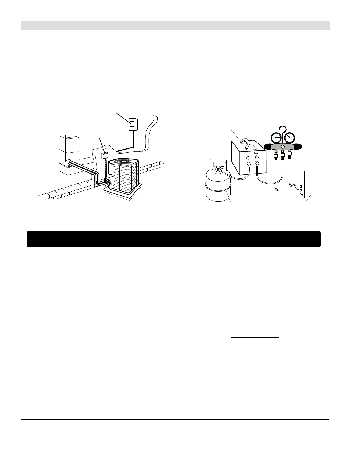
Recovering Refrigerant from Existing System9
RECOVERING
REFRIGERANT FROM SYSTEM
DISCONNECT POWER
Disconnect all power to the existing outdoor unit at the disconnect
1
switch or main fuse box/breaker panel.
MAIN FUSE BOX/BREAKER PANEL
SERVICE
DISCONNECT
SWITCH
RECOVERING REFRIGERANT
Remove existing HCFC−22 refrigerant using one of the following procedures:
3
IMPORTANT Some system configurations may contain higher than normal refrigerant charge due to either large internal coil volumes,
and/or long line sets.
CONNECT MANIFOLD GAUGE SET
Connect a gauge set, clean recovery cylinder and a recovery
2
machine to the service ports of the existing unit. Use the
instructions provided with the recovery machine to make the
connections.
MANIFOLD GAUGES
RECOVERY MACHINE
LOW
CLEAN RECOVERY
CYLINDER
OUTDOOR UNIT
HIGH
METHOD 1:
Us this method if the existing outdoor unit is not equipped with shut−off valves, or if the unit is not operational and you plan to use the existing
HCFC−22 to flush the system.
Remove all HCFC−22 refrigerant from the existing system. Check gauges after shutdown to confirm that the entire system is completely void of
refrigerant.
METHOD 2:
Use this method if the existing outdoor unit is equipped with manual shut−off valves, and you plan to use new HCFC−22 refrigerant to flush the
system.
The following devices could prevent full system charge recovery into the outdoor unit:
S Outdoor unit’s high or low−pressure switches (if applicable) when tripped can cycle the compressor OFF.
S Compressor can stop pumping due to tripped internal pressure relief valve.
S Compressor has internal vacuum protection that is designed to unload the scrolls (compressor stops pumping) when the pressure ratio meets
a certain value or when the suction pressure is as high as 20 psig. (Compressor suction pressures should never be allowed to go into a vacuum.
Prolonged operation at low suction pressures will result in overheating of the scrolls and permanent damage to the scroll tips, drive bearings and
internal seals.)
Once the compressor can not pump down to a lower pressure due to one of the above system conditions, shut off the vapor valve. Turn OFF the
main power to unit and use a recovery machine to recover any refrigerant left in the indoor coil and line set.
Perform the following task:
A Start the existing HCFC−22 system in the cooling mode and close the liquid line valve.
B Use the compressor to pump as much of the existing HCFC−22 refrigerant into the outdoor unit until the outdoor system is full. Turn the outdoor unit
main power OFF and use a recovery machine to remove the remaining refrigerant from the system.
NOTE It may be necessary to bypass the low pressure switches (if equipped) to ensure complete refrigerant evacuation.
C When the low side system pressures reach 0 psig, close the vapor line valve.
D Check gauges after shutdown to confirm that the valves are not allowing refrigerant to flow back into the low side of the system.
Page 10
Page 11

Unit Placement10
See Unit Dimensions on Page3 for sizing mounting slab,
platforms or supports. Refer to Figure 7 for mandatory
installation clearance requirements.
*
*
*
*
NOTES:
S Service panel access clearance of 30 in. (762 mm) must be
maintained.
S Clearance to one of the other three sides must be 36 in. (914
S Clearance on one of the remaining two sides may be 12 in. (305
.
mm)
mm) and the final side may be 6 in. (152 mm)
.
S Clearance required on top of unit is 48 in. (1219 mm).
S A clearance of 24 in. (610 mm) must be maintained between two
units.
INSTALL UNIT AWAY
FROM WINDOWS
TWO 90° ELBOWS INSTALLED
IN LINE SET WILL REDUCE
LINE SET VIBRATION.
Figure 8. Outside Unit Placement
PLACING OUTDOOR UNIT ON SLAB
When installing a unit at grade level, the top of the slab
should be high enough above the grade so that water from
higher ground would not collect around the unit as
illustrated in Figure 9.
DISCHARGE AIR
BUILDING
STRUCTURE
Figure 7. Installation Clearances
POSITIONING CONSIDERATIONS
CAUTION
In order to avoid injury, take proper precaution when lifting heavy objects.
Consider the following when positioning the unit:
S Some localities are adopting sound ordinances based
on the unit’s sound level registered from the adjacent
property, not from the installation property. Install the
unit as far as possible from the property line.
S When possible, do not install the unit directly outside
a window. Glass has a very high level of sound
transmission. For proper placement of unit in relation
to a window see the provided illustration in Figure 8.
MOUNTING
SLAB
GROUND LEVEL
Figure 9. Typical Slab Mounting at Ground Level
Slab may be level or have a slope tolerance away from the
building of not more than two degrees, or 2 inches per 5
feet (51 mm per 1524 mm) as illustrated in Figure 9.
INSTALLING OUTDOOR UNIT ON ROOF
Install the unit at a minimum of 4 inches (102 mm) above
the surface of the roof. Ensure the weight of the unit is
properly distributed over roof joists and rafters. Redwood
or steel supports are recommended.
S When possible, do not install the unit directly outside
a window. Glass has a very high level of sound
transmission. For proper placement of unit in relation
to a window see the provided illustration in Figure 8.
Page 11
Page 12

New or Replacement Line Set11
This section provides information on new installation or
replacement of existing line set. If a new or replacement
line set is not required, then proceed to Brazing
Connections on Page 14.
If refrigerant lines are routed through a wall, seal and
isolate the opening so vibration is not transmitted to the
building. Pay close attention to line set isolation during
installation of any HVAC system. When properly isolated
from building structures (walls, ceilings. floors), the
refrigerant lines will not create unnecessary vibration and
subsequent sounds.
Also, consider the following when placing and installing a
high−efficiency air conditioner:
REFRIGERANT LINE SET
Field refrigerant piping consists of liquid and suction lines
from the outdoor unit (braze connections) to the indoor unit
coil (flare or braze connections). Use Lennox L15 (braze,
non−flare) series line set, or use field−fabricated refrigerant
lines as listed in Table 2.
Table 2. Refrigerant Connections and Line Set
Requirements
Valve Field Connections and Recommended Line
Model
NOTE Some applications may required a field provided 7/8" to
1−1/8" adapter
NOTE − When installing refrigerant lines longer than 50
feet, contact Lennox Technical Support Product
Applications for assistance or Lennox piping manual. To
obtain the correct information from Lennox, be sure to
communicate the following points:
S Model (TPA*S4) and size of unit (e.g. −060).
S Line set diameters for the unit being installed as listed
S Number of elbows and if there is a rise or drop of the
LIQUID LINE FILTER DRIER12 INSTALLATION OR
REPLACEMENT
The filter drier (one is shipped with each unit) must be field
installed in the liquid line between the outdoor unit’s liquid
line service valve and the indoor coil’s metering device
(TXV) as illustrated in Figure 10. This filter drier must be
installed to ensure a clean, moisture−free system. Failure
Set
−024
−036
−048
−060
Liquid
Line
3/8 in.
(10 mm)
3/8 in.
(10 mm)
3/8 in.
(10 mm)
Suction
Line
3/4 in.
(19 mm)
7/8 in.
(22 mm)
1−1/8 in.
(29 mm)
L15 Line Set
L15 line set sizes are dependent on
unit matchup. See Engineering
Handbook to determine correct line
set sizes.
Field Fabricated
in Table 2 and total length of installation.
piping.
to install the bi−flow filter drier will void the warranty. A
replacement filter drier is available from Lennox. See
Brazing Connections on Page 12 for special procedures
on brazing filter drier connections to the liquid line.
BRAZE CONNECTION POINTS
LIQUID
LINE
OUTDOOR
UNIT
LIQUID LINE
SERVICE VALVE
LINE
LIQUID LINE
FILTER DRIER
Figure 10. Typical Bi−Flow Liquid Line Filter
Drier Installation
LINE SET ISOLATION
CAUTION
Brazing alloys and flux contain materials which are
hazardous to your health.
Avoid breathing vapors or fumes from brazing
operations. Perform operations only in well ventilated
areas.
Wear gloves and protective goggles or face shield to
protect against burns.
Wash hands with soap and water after handling brazing
alloys and flux.
IMPORTANT
The Environmental Protection Agency (EPA) prohibits
the intentional venting of HFC refrigerants during
maintenance, service, repair and disposal of appliance.
Approved methods of recovery, recycling or reclaiming
must be followed.
IMPORTANT
If this unit is being matched with an approved line set
or indoor unit coil which was previously charged with
mineral oil, or if it is being matched with a coil which
was manufactured before January of 1999, the coil
and line set must be flushed prior to installation. Take
care to empty all existing traps. Polyol ester (POE) oils
are used in Lennox units charged with HFC−410A
refrigerant. Residual mineral oil can act as an
insulator, preventing proper heat transfer. It can also
clog the expansion device, and reduce the system
performance and capacity.
Failure to properly flush the system per the
instructions below will void the warranty.
Page 12
Page 13

LINE SET
INSTALLATION
Line Set Isolation The following illustrations are
examples of proper refrigerant line set isolation:
REFRIGERANT LINE SET TRANSITION
FROM VERTICAL TO HORIZONTAL
ANCHORED HEAVY NYLON
WIRE TIE OR AUTOMOTIVE
MUFFLER-TYPE HANGER
AUTOMOTIVE
MUFFLER-TYPE HANGER
IMPORTANT Refrigerant lines must not contact structure.
REFRIGERANT LINE SET INSTALLING
VERTICAL RUNS (NEW CONSTRUCTION SHOWN)
NOTE Insulate liquid line when it is routed through areas where the
surrounding ambient temperature could become higher than the
temperature of the liquid line or when pressure drop is equal to or greater
than 20 psig.
IMPORTANT Refrigerant lines must not contact wall
OUTSIDE WALL
VAPOR LINE
LIQUID LINE
WALL
STUD
STRAP LIQUID LINE TO
VAPOR LINE
LIQUID LINE
NON−CORROSIVE
METAL SLEEVE
VAPOR LINE − WRAPPED
IN ARMAFLEX
REFRIGERANT LINE SET INSTALLING
HORIZONTAL RUNS
To hang line set from joist or rafter, use either metal strapping material
or anchored heavy nylon wire ties.
WIRE TIE (AROUND
VAPOR LINE ONLY)
8 FEET (2.43 METERS)
STRAPPING
MATERIAL (AROUND
VAPOR LINE ONLY)
TAPE OR
WIRE TIE
FLOOR JOIST OR
ROOF RAFTER
8 FEET (2.43 METERS)
NON−CORROSIVE
METAL SLEEVE
STRAP THE VAPOR LINE TO THE JOIST
OR RAFTER AT 8 FEET (2.43 METERS)
INTERVALS THEN STRAP THE LIQUID
LINE TO THE VAPOR LINE.
TAPE OR
WIRE TIE
WIRE TIE
INSIDE WALL
WOOD BLOCK
BETWEEN STUDS
SLEEVE
VAPOR LINE WRAPPED
WITH ARMAFLEX
OUTSIDE
WALL
PVC
PIPE
FIBERGLASS
INSULATION
CAULK
STRAP
NON−CORROSIVE
METAL SLEEVE
WIRE TIE
WOOD BLOCK
WIRE TIE
STRAP
LIQUID
LINE
NOTE Similar installation practices should be used if line set is
to be installed on exterior of outside wall.
FLOOR JOIST OR
ROOF RAFTER
WARNING Polyol ester (POE) oils used with HFC−410A
refrigerant absorb moisture very quickly. It is very important that the
refrigerant system be kept closed as much as possible. DO NOT
remove line set caps or service valve stub caps until you are ready
to make connections.
Figure 11. Line Set Installation
Page 13
Page 14

BRAZING
CONNECTIONS13
CUT AND DEBUR
Cut ends of the refrigerant lines square
1
(free from nicks or dents) and debur the
ends. The pipe must remain round and do
not pinch end of the line.
ATTACHED GAUGES
A Connect gauge set low pressure side to liquid line service
3
valve.
B Connect gauge set center port to bottle of nitrogen with
regulator.
SERVICE PORT MUST BE OPEN TO ALLOW EXIT
INDOOR
UNIT
NOTE − Use silver alloy brazing rods with five or six percent minimum silver
alloy for copper−to−copper brazing, 45 percent alloy for copper−to−brass and
copper−to−steel brazing.
CAP AND CORE REMOVAL
Remove service cap and core
2
from both the vapor and liquid line
service ports.
HIGHLOW
B
ATTACH
POINT FOR NITROGEN
VAPOR LINE
GAUGES
VAPOR LINE
SERVICE
VALV E
OUTDOOR
UNIT
USE REGULATOR TO FLOW
NITROGEN AT 1 TO 2 PSIG.
WRAP SERVICE VALVE
To protect components during
4
brazing, wrap a wet cloth around
the liquid line service valve body
and copper tube stub and use
another wet cloth underneath the
valve body to protect the base
paint.
BRAZE LINE SET
Braze the liquid line to the liquid line
6
service valve. Turn off nitrogen flow.
POINT FLAME AWAY FROM
SERVICE VALVE
LIQUID LINE
LIQUID LINE SERVICE
5
NOTE The fixed orifice or check
expansion valve metering device at the
indoor unit will allow low pressure
nitrogen to flow through the system.
VALV E
FLOW NITROGEN
Flow regulated nitrogen (at 1 to 2 psig) through the refrigeration
gauge set into the valve stem port connection on the liquid line service
valve and out of the valve stem port connection on the vapor service
valve.
INSTALL SERVICE PORT CAPS ONLY
After all connections have been brazed, disconnect manifold gauge
7
set from service ports, cool down piping with wet rag and remove all
wrappings. Do not reinstall cores until after evacuation procedure.
Reinstall service port caps if desired to close off refrigerant ports.
A
LOW
NITROGEN
HIGH
USE REGULATOR TO
FLOW NITROGEN AT 1
TO 2 PSIG.
NITROGEN
WARNING Allow braze joint to cool before removing the wet
rag from the service valve. (TEMPERATURES ABOVE 250ºF
CAN DAMAGE VALVE SEALS
IMPORTANT Connect gauge set low pressure side to vapor
line service valve and repeat procedure starting at paragraph 4
for brazing the liquid line to service port valve.
SERVICE PORT
Figure 12. Brazing Connections
Page 14
SERVICE PORT CORE
SERVICE PORT CAP
Page 15

Metering Devices and Flushing the System14
FLUSHING
LINE SET AND INDOOR COIL
TYPICAL FIXED ORIFICE REMOVAL
1
DISTRIBUTOR TUBES
LIQUID LINE ORIFICE HOUSING
TEFLON RING
FIXED ORIFICE
BRASS NUT
DISTRIBUTOR
ASSEMBLY
(Uncased Coil Shown)
A On fully cased coils, remove the coil access and plumbing panels.
B Remove any shipping clamps holding the liquid line and distributor
assembly.
C Using two wrenches, disconnect liquid line from liquid line orifice
housing. Take care not to twist or damage distributor tubes during
this process.
D Remove and discard fixed orifice, valve stem assembly if present
and Teflon washer as illustrated above.
E Use a field−provided fitting to temporary reconnect the liquid line to
the indoor unit’s liquid line orifice housing.
F Replace with expansion valve.
CONNECT GAUGES AND EQUIPMENT FOR
FLUSHING PROCEDURE
2
VAPOR LINE
SERVICE VALVE
EXISTING
INDOOR
UNIT
LIQUID LINE SERVICE
RECOVERY
CYLINDER
VALV E
LIQUID
D
A Inverted HCFC−22 cylinder with clean refrigerant to the vapor service
valve.
B HCFC−22 gauge set (low side) to the liquid line valve.
C HCFC−22 gauge set center port to inlet on the recovery machine with
an empty recovery tank to the gauge set.
D Connect recovery tank to recovery machines per machine
instructions.
REMOVE AND DISCARD
WHITE TEFLON SEAL (IF
INVERTED HCFC−22
CYLINDER CONTAINS
CLEAN HCFC−22 TO BE
USED FOR FLUSHING.
A
1
VAPOR
PRESENT)
NEW
OUTDOOR
UNIT
B
C
LIQUID LINE ASSEMBLY
(INCLUDES STRAINER)
GAUGE
MANIFOLD
LOW
OPENED
TANK
RETURN
INLET
DISCHARGE
RECOVERY MACHINE
CLOSED
HIGH
TYPICAL EXPANSION VALVE REMOVAL AND
REPLACEMENT PROCEDURE
(Uncased Coil Shown)
TWO PIECE PATCH PLATE
(UNCASED COIL ONLY)
DISTRIBUTOR
TUBES
OR
A On fully cased coils, remove the coil access and plumbing panels.
B Remove any shipping clamps holding the liquid line and distributor as-
C Disconnect the equalizer line from the expansion valve equalizer line
D Remove the vapor line sensing bulb.
E Disconnect the liquid line from the expansion valve at the liquid line as-
F Disconnect the expansion valve from the liquid line orifice housing.
G Remove and discard expansion valve and the two Teflon rings.
H Use a field−provided fitting to temporary reconnect the liquid line to the
I Reverse above order to install.
CAUTION This procedure should not be performed on systems
which contain contaminants (Example compressor burn out.
DISTRIBUTOR
ASSEMBLY
MALE EQUALIZER
LINE FITTING
sembly.
fitting on the vapor line.
sembly.
Take care not to twist or damage distributor tubes during this process.
indoor unit’s liquid line orifice housing.
LIQUID LINE
SENSING BULB
FLUSHING LINE SET
The line set and indoor unit coil must be flushed with at least the
3
same amount of clean refrigerant that previously charged the system. Check the charge in the flushing cylinder before proceeding.
B
A Set the recovery machine for liquid recovery and start the recov-
ery machine. Open the gauge set valves to allow the recovery
machine to pull a vacuum on the existing system line set and indoor unit coil.
B Invert the cylinder of clean HCFC−22 and open its valve to allow
liquid refrigerant to flow into the system through the vapor line
valve. Allow the refrigerant to pass from the cylinder and through
the line set and the indoor unit coil before it enters the recovery
machine.
C After all of the liquid refrigerant has been recovered, switch the
recovery machine to vapor recovery so that all of the HCFC−22
vapor is recovered. Allow the recovery machine to pull down to 0
the system.
D Close the valve on the inverted HCFC−22 drum and the gauge
set valves. Pump the remaining refrigerant out of the recovery
machine and turn the machine off.
ORIFICE
HOUSING
EQUALIZER
LINE
STUB END
TEFLON
RING
VAPOR
EXPANSION
VALV E
LIQUID LINE
ASSEMBLY WITH
BRASS NUT
LINE
TEFLON
RING
SENSING
LINE
LIQUID
LINE
Page 15
Page 16

Leak Testing the System15
LEAK TEST
LINE SET AND INDOOR COIL
CONNECT GAUGE SET
A Connect an HFC−410A manifold gauge set high
1
pressure hose to the vapor valve service port.
B With both manifold valves closed, connect the
cylinder of HFC−410A refrigerant to the center port
of the manifold gauge set.
NOTE Later in the procedure, the HFC−410A
container will be replaced by the nitrogen container.
NOTE Normally, the high pressure hose is connected to the liquid line port. However, connecting it to the vapor port better protects the manifold gauge set from high
pressure damage.
HIGHLOW
MANIFOLD GAUGE SET
OUTDOOR UNIT
USE REGULATOR TO FLOW
NITROGEN AT 1 TO 2 PSIG.
NITROGEN
TEST FOR LEAKS
After the line set has been connected to the indoor unit and air conditioner, check the line set connections and
2
indoor unit for leaks. Use the following procedure to test for leaks:
A With both manifold valves closed, connect the cylinder of HFC−410A refrigerant to the center port of the manifold gauge set. Open
the valve on the HFC−410A cylinder (vapor only).
B Open the high pressure side of the manifold to allow HFC−410A into the line set and indoor unit. Weigh in a trace amount of
HFC−410A. [A trace amount is a maximum of two ounces (57 g) refrigerant or three pounds (31 kPa) pressure]. Close the valve on
the HFC−410A cylinder and the valve on the high pressure side of the manifold gauge set. Disconnect the HFC−410A cylinder.
C Connect a cylinder of dry nitrogen with a pressure regulating valve to the center port of the manifold gauge set.
D Adjust dry nitrogen pressure to 150 psig (1034 kPa). Open the valve on the high side of the manifold gauge set in order to pressurize the
line set and the indoor unit.
E After a few minutes, open one of the service valve ports and verify that the refrigerant added to the system earlier is measurable
with a leak detector.
F After leak testing disconnect gauges from service ports.
HFC−410A
WARNING
When using a high pressure gas such as
dry nitrogen to pressurize a refrigeration
or air conditioning system, use a
regulator that can control the pressure
down to 1 or 2 psig (6.9 to 13.8 kPa).
WARNING
Refrigerant can be harmful if it is inhaled. Refrigerant
must be used and recovered responsibly.
Failure to follow this warning may result in personal injury
or death.
B
TO VAPOR
SERVICE VALVE
Fire, Explosion and Personal Safety
Hazard.
Failure to follow this warning could
result in damage, personal injury or
death.
Never use oxygen to pressurize or
purge refrigeration lines. Oxygen,
when exposed to a spark or open
flame, can cause damage by fire
and/or an explosion, that could result
in personal injury or death.
IMPORTANT
A
WARNING
Leak detector must be capable of sensing HFC
refrigerant.
Page 16
Page 17

Evacuating the System16
EVACUATING
LINE SET AND INDOOR COIL
CONNECT GAUGE SET
NOTE Remove cores from service valves (if not already done).
1
A Connect low side of manifold gauge set
with 1/4 SAE in−line tee to vapor line
service valve
B Connect high side of manifold gauge
set to liquid line service valve
C Connect micron gauge available
connector on the 1/4 SAE in−line tee.
D Connect the vacuum pump (with
vacuum gauge) to the center port of the
manifold gauge set. The center port line
will be used later for both the HFC−410A
and nitrogen containers.
USE REGULATOR TO FLOW
NITROGEN AT 1 TO 2 PSIG.
HFC−410A
VACUUM PUMP
OUTDOOR
UNIT
A
B
A34000 1/4 SAE TEE WITH
SWIVEL COUPLER
500
C
D
MICRON
GAUGE
LOW
TO VAPOR
SERVICE VALVE
TO LIQUID LINE
SERVICE VALVE
MANIFOLD
GAUGE SET
HIGH
NITROGEN
EVACUATE THE SYSTEM
A Open both manifold valves and start the vacuum pump.
2
B Evacuate the line set and indoor unit to an absolute pressure of 23,000 microns (29.01 inches of mercury).
NOTE During the early stages of evacuation, it is desirable to close the manifold gauge valve at least once. A rapid rise in pressure
indicates a relatively large leak. If this occurs, repeat the leak testing procedure.
NOTE The term absolute pressure means the total actual pressure within a given volume or system, above the absolute zero of
pressure. Absolute pressure in a vacuum is equal to atmospheric pressure minus vacuum pressure.
C When the absolute pressure reaches 23,000 microns (29.01 inches of mercury), close the manifold gauge valves, turn off the vacuum
pump and disconnect the manifold gauge center port hose from vacuum pump. Attach the manifold center port hose to a dry nitrogen
cylinder with pressure regulator set to 150 psig (1034 kPa) and purge the hose. Open the manifold gauge valves to break the vacuum in
the line set and indoor unit. Close the manifold gauge valves.
D Shut off the dry nitrogen cylinder and remove the manifold gauge hose from the cylinder. Open the manifold gauge valves to release the
dry nitrogen from the line set and indoor unit.
E Reconnect the manifold gauge to the vacuum pump, turn the pump on, and continue to evacuate the line set and indoor unit until the
absolute pressure does not rise above 500 microns (29.9 inches of mercury) within a 20−minute period after shutting off the vacuum pump
and closing the manifold gauge valves.
F When the absolute pressure requirement above has been met, disconnect the manifold hose from the vacuum pump and connect it to an
upright cylinder of HFC−410A refrigerant. Open the manifold gauge valve 1 to 2 psig in order to release the vacuum in the line set and
indoor unit.
G Perform the following:
RECOMMEND
MINIMUM 3/8" HOSE
S Close manifold gauge valves.
S Shut off HFC−410A cylinder.
S Reinstall service valve cores by removing manifold hose from service valve. Quickly install cores with
core tool while maintaining a positive system pressure.
S Replace the stem caps and secure finger tight, then tighten an additional one−sixth (1/6) of a turn as
illustrated.
11
10
9
8
7
12
6
1/6 TURN
1
2
3
4
5
Page 17
Page 18

IMPORTANT
Use a thermocouple or thermistor electronic vacuum
gauge that is calibrated in microns. Use an instrument
capable of accurately measuring down to 50 microns.
WARNING
Danger of Equipment Damage. Avoid deep vacuum
operation. Do not use compressors to evacuate a
system. Extremely low vacuums can cause internal
arcing and compressor failure. Damage caused by
deep vacuum operation will void warranty.
Evacuating the system of non−condensables is critical for
proper operation of the unit. Non−condensables are
defined as any gas that will not condense under
temperatures and pressures present during operation of
an air conditioning system. Non−condensables and water
suction combine with refrigerant to produce substances
that corrode copper piping and compressor parts.
Electrical17
In the U.S.A., wiring must conform with current local codes
and the current National Electric Code (NEC). In Canada,
wiring must conform with current local codes and the current
Canadian Electrical Code (CEC).
Refer to the furnace or air handler installation instructions
for additional wiring application diagrams and refer to unit
nameplate for minimum circuit ampacity and maximum
overcurrent protection size.
24VAC TRANSFORMER
Use the transformer provided with the furnace or air
handler for low-voltage control power (24VAC − 40 VA
minimum)
SIZE CIRCUIT AND INSTALL DISCONNECT SWITCH
Refer to the unit nameplate for minimum circuit ampacity, and maximum
fuse or circuit breaker (HACR per NEC). Install power wiring and properly
sized disconnect switch.
MAIN FUSE BOX/
BREAKER PANEL
SERVICE
DISCONNECT
SWITCH
NOTE Units are approved for use only with copper conductors.
Ground unit at disconnect switch or to an earth ground.
WARNING
Electric Shock Hazard. Can cause injury or death. Unit must be grounded in accordance with national and
local codes.
Line voltage is present at all components when unit is not in operation on units with single-pole contactors.
Disconnect all remote electric power supplies before opening access panel. Unit may have multiple power
supplies.
INSTALL THERMOSTAT
Install room thermostat (ordered separately) on an inside wall
approximately in the center of the conditioned area and 5 feet (1.5m) from
the floor. It should not be installed on an outside wall or where it can be
affected by sunlight or drafts.
THERMOSTAT
5 FEET
(1.5M)
NOTE 24VAC, Class II circuit connections are made in the control
panel.
Page 18
Page 19

ROUTING HIGH VOLTAGE/ GROUND AND CONTROL WIRING
HIGH VOLTAGE / GROUND WIRES
Any excess high voltage field wiring should be trimmed and secured away from any low voltage field wiring. To facilitate a conduit, a cutout is
located in the bottom of the control panel. Connect conduit to the control panel using a proper conduit fitting.
CONTROL WIRING
Install low voltage wiring from outdoor to indoor unit and from
thermostat to indoor unit as illustrated.
A Run 24VAC control wires through hole with grommet.
B Make 24VAC thermostat wire connections to CMC1.
NOTE Do not bundle any excess 24VAC control wires inside
control panel.
NOTE For proper voltages, select thermostat wire (control
wires) gauge per Table above.
WIRE RUN LENGTH AWG# INSULATION TYPE
LESS THAN 100’ (30 METERS) 18 TEMPERATURE RATING
MORE THAN 100’ (30 METERS) 16 35ºC MINIMUM.
TYPICAL CONTROL WIRING
Low Voltage Wiring
Thermostat Indoor Unit
R
C
W1
G
O
Y1
power
common
1st. stage aux. heat
indoor blower
reversing valve
compressor
(SOME CONNECTIONS MAY NOT APPLY. REFER
TO SPECIFIC THERMOSTAT AND INDOOR UNIT.)
R
C
W1
W2
W3
G
1st. stage aux. heat
power
common
Outdoor Unit
R
W1
Y1
Low Voltage Wiring (with Auxiliary Heat)
THREE PHASE
HIGH VOLTAGE
CONNECTIONS
(CONTACTOR)
GROUND
CUTOUT FOR HIGH
VOLTAGE CONDUIT
A
GROMMET AND WIRE TIE FOR
C
NOTE Wire tie provides low voltage wire strain relief and
to maintain separation of field installed low and high voltage
circuits.
O
HIGH VOLTAGE
CONNECTIONS
(CONTACTOR)
CONTROL WIRES
SINGLE PHASE
DEFROST CONTROL
BOARD (CMC1)
B
CONTROL WIRE
CONNECTIONS
HIGH VOLTAGE
FIELD WIRING
LOW VOLTAGE
FIELD WIRING
FACTORY
WIRING
DEFROST CONTROL
BOARD (CMC1)
B
CONTROL WIRE
CONNECTIONS
Thermostat Indoor Unit Outdoor Unit
R
C
E
W1
G
O
Y1
power
common
emergency heat
1st. stage aux. heat
indoor blower
reversing valve
compressor
(SOME CONNECTIONS MAY NOT APPLY. REFER TO
SPECIFIC THERMOSTAT AND INDOOR UNIT.)
R
C
emer.
heat
relay
W1
1st. stage aux. heat
W2
W3
G
common
outdoor t’stat
power
W1
Y1
R
C
GROUND
CUTOUT FOR HIGH
VOLTAGE CONDUIT
A
GROMMET AND WIRE TIE
O
FOR CONTROL WIRES
Page 19
Page 20

GAUGE SET
CONNECTIONS FOR TESTING AND CHARGING
TRUE SUCTION PORT
B
CONNECTION
REFRIGERANT TANK
MANIFOLD GAUGE SET
LOW
HIGH
OUTDOOR UNIT
CHARGE IN
LIQUID PHASE
DIGITAL SCALE
D
TEMPERATURE
SENSOR
A Close manifold gauge set valves and connect the center hose to a cylinder of HFC−410A. Set
for liquid phase charging.
INSIDE OUTDOOR UNIT
B Connect the manifold gauge set’s low pressure side to the true suction port.
C Connect the manifold gauge set’s high pressure side to the liquid line service port.
D Position temperature sensor on liquid line near liquid line service port.
Figure 13. Gauge Set Setup and Connections
Servicing Units Void of Charge18
If the outdoor unit is void of refrigerant, clean the system
using the procedure described below.
1. Leak check system using procedure outlined on Page
16.
2. Evacuate the system using procedure outlined on
Page 17.
3. Use nitrogen to break the vacuum and install a new
filter drier in the system.
4. Evacuate the system again using procedure outlined
on Page 17.
5. Weigh in refrigerant using procedure outlined in Figure
15.
Unit Start−Up19
IMPORTANT
If unit is equipped with a crankcase heater, it should be
energized 24 hours before unit start−up to prevent
compressor damage as a result of slugging.
1. Rotate fan to check for binding.
2. Inspect all factory− and field−installed wiring for loose
connections.
A
C
TO LIQUID
LINE SERVICE
VALV E
3. After evacuation is complete, open the liquid line and
suction line service valves to release the refrigerant
charge (contained in outdoor unit) into the system.
4. Replace the stem caps and tighten as specified in
Operating Service Valves on Page 8.
5. Check voltage supply at the disconnect switch. The
voltage must be within the range listed on the unit’s
nameplate. If not, do not start the equipment until you
have consulted with the power company and the
voltage condition has been corrected.
6. Set the thermostat for a cooling demand. Turn on
power to the indoor indoor unit and close the outdoor
unit disconnect switch to start the unit.
7. Recheck voltage while the unit is running. Power must
be within range shown on the nameplate.
8. Check system for sufficient refrigerate by using the
procedures listed under Start−Up and Charging
Procedures.
TEMPERATURE SENSOR
(LIQUID LINE)
LIQUID LINE
SERVICE
PORT
System Refrigerant20
This section outlines procedures for:
1. Connecting gauge set for testing and charging;
2. Checking and adjusting indoor airflow;
3. Adding or removing refrigerant.
Page 20
Page 21

ADDING OR REMOVING REFRIGERANT
This system uses HFC−410A refrigerant which operates at much higher pressures than HCFC−22. The pre−installed liquid
line filter drier is approved for use with HFC−410A only. Do not replace it with components designed for use with HCFC−22.
This unit is NOT approved for use with coils which use capillary tubes or fixed orifices as a refrigerant metering device.
Check airflow using the Delta−T (DT) process using the illustration in Figure 14.
AIRFLOW
INDOOR COIL
Temperature of air
entering indoor
coil ºF
A
Wet−bulb ºF
80 24 24 24 23 23 2222 22 20 19 18 17 16 15
78 23 23 23 22 22 2121 20 19 18 17 16 15 14
76 22 22 22 21 21 2019 19 18 17 16 15 14 13
Dry−bulb
74 21 21 21 20 19 1918 17 16 16 15 14 13 12
72 20 20 19 18 17 1716 15 15 14 13 12 11 10
70 19 19 18 18 17 1716 15 15 14 13 12 11 10
57 58 59 60 61 62 63 64 65 66 67 68 69 70
DT
DRY
BULB
C
53º
T
19º
Drop
air flow
air flow
B
B
64º
DRY BULB
WET BULB
All temperatures are expressed in ºF
INDOOR COIL
Use the following procedure to adjust for optimal air flow across the indoor coil:
1. Determine the desired DT Measure entering air temperature using dry bulb (A) and wet bulb (B). DT
is the intersecting value of A and B in the Table (see triangle).
2. Find temperature drop across coil Measure the coil’s dry bulb entering and leaving air temperatures
(A and C). Temperature Drop Formula: (T
3. Determine if fan needs adjustment If the difference between the measured T
DT (T
–DT) is within +3º, no adjustment is needed. See example below:
Drop
) = A minus C.
Drop
and the desired
Drop
Assume DT = 15 and A temp. = 72º, these C temperatures would necessitate stated actions:
A
72º
Cº T
53º 19 – 15 = 4 Increase the airflow
58º 14 – 15 = −1 (within +3º range) no change
62º 10 – 15 = −5 Decrease the airflow
– DT = ºF ACTION
Drop
4. Adjust the fan speed See indoor unit instructions to increase/decrease fan speed.
Figure 14. Checking Indoor Airflow over Evaporator Coil using Delta−T Chart
Changing air flow affects all temperatures; recheck
temperatures to confirm that the temperature drop
and DT are within +3º.
Page 21
Page 22

Use
WEIGH IN method for adding initial refrigerant charge, and then use SUBCOOLING method for
verifying refrigerant charge.
WEIGH IN
CHARGING METHOD
CALCULATING SYSTEM CHARGE FOR OUTDOOR
UNIT VOID OF CHARGE
If the system is void of refrigerant, first, locate and repair any leaks and then weigh in the refrigerant charge into the
unit. To calculate the total refrigerant charge:
Adjust amount. for variation
Amount specified on
nameplate
in line set length listed on
line set length table below.
+
Total charge
=
Refrigerant Charge per Line Set Length
Liquid Line
Set Diameter
3/8" (9.5 mm)
*If line length is greater than 15 ft. (4.6 m), add this amount. If
line length is less than 15 ft. (4.6 m), subtract this amount.
NOTE Insulate liquid line when it is routed through areas where the surrounding ambient temperature could
become higher than the temperature of the liquid line or when pressure drop is equal to or greater than 20 psig.
NOTE The above nameplate is for illustration purposes only. Go to actual nameplate on outdoor unit for
charge information.
Ounces per 5 feet (g per 1.5 m)
adjust from 15 feet (4.6 m) line set*
3 ounce per 5’ (85 g per 1.5 m)
Figure 15. Using Weigh In Method
1 Check the airflow as illustrated in Figure 14 to be sure the indoor airflow is as required. (Make any air
SUBCOOLING
USE COOLING
MODE
60ºF (15º)
USE HEATING
MODE
SATº
LIQº –
SCº =
flow adjustments before continuing with the following procedure.)
2 Measure outdoor ambient temperature; determine whether to use cooling mode or heating mode to
check charge.
3 Connect gauge set.
4 Check Liquid and Vapor line pressures. Compare pressures with Normal Operating Pressures in either
Table 5 or 6, (The reference table is a general guide. Expect minor pressure variations. Significant
differences may mean improper charge or other system problem.)
5 Set thermostat for heat/cool demand, depending on mode being used:
Using cooling modeWhen the outdoor ambient temperature is 60°F (15°C) and above. Target
subcooling values in table below are based on 70 to 80°F (21−27°C) indoor return air temperature; if
necessary, operate heating to reach that temperature range; then set thermostat to cooling mode setpoint
to 68ºF (20ºC). When pressures have stabilized, continue with step 6.
Using heating modeWhen the outdoor ambient temperature is below 60°F (15°C). Target subcooling
values in table below are based on 65−75°F (18−24°C) indoor return air temperature; if necessary, operate
cooling to reach that temperature range; then set thermostat to heating mode setpoint to 77ºF (25ºC). When
pressures have stabilized, continue with step 6.
6 Read the liquid line temperature; record in the LIQº space.
7 Read the liquid line pressure; then find its corresponding temperature in the temperature/ pressure chart
listed in Table 7 and record it in the SATº space.
8 Subtract LIQº temp. from SATº temperature to determine subcooling; record it in SCº space.
9 Compare SCº results with either Table 3 or 4, being sure to note any additional charge for line set and/or
match−up.
10 If subcooling value is greater than shown in the below table for the applicable unit size, remove refrigerant;
if less than shown, add refrigerant.
11 If refrigerant is added or removed, repeat steps 6 through 10 to verify charge.
Figure 16. Using Subcooling Method
Page 22
Page 23

Table 3. Subcooling (SC) Values TXV System − ºF
(ºC) +1ºF (0.5ºC)
T Voltage 220/240VAC, 1−Phase, 50 Hertz
5F(5C)* −024 −036 −048
Cooling
65 (18) 19 6 11
75 (24) 19 7 12
85 (29) 19 8 12
95 (35) 20 9 13
105 (41) 20 9 13
115 (45) 20 9 13
Heating
60 (15) 8 8 6
50 (10) 8 8 6
40 (4) 8 8 6
30 (−1) 8 8 6
10 (−7) 8 8 6
*Temperature of the air entering the outside coil.
Use this Table to perform maintenance checks; it is not a procedure for charging the
system. Minor variations in these pressures may be due to differences in installations.
IMPORTANT
Significant deviations could mean that the system is not properly charged or that a
problem exists with some component in the system.
Table 4. Subcooling (SC) Values TXV System − ºF
(ºC) +1ºF (0.5ºC)
M Voltage 380/420VAC, 3−Phase, 50 Hertz
5F(5C)* −036 −048 −060
Cooling
65 (18) 6 11 12
75 (24) 7 12 13
85 (29) 8 12 14
95 (35) 9 13 15
105 (41) 9 13 15
115 (45) 9 13 15
Heating
60 (15) 8 6 9
50 (10) 8 6 9
40 (4) 8 6 9
30 (−1) 8 6 9
10 (−7) 8 6 9
*Temperature of the air entering the outside coil.
Table 5. Normal Operating Pressures Liquid +10
and Vapor +5 Psig (1 Phase)
T Voltage 220/240VAC, 1−Phase, 50 Hertz
−024 −036 −048
Cooling
5F(5C)* Liquid / Vapor Liquid / Vapor Liquid / Vapor
65 (18) 268 / 129 268 / 141 247 / 138
75 (24) 311 / 133 309 / 143 286 / 141
85 (29) 358 / 136 354 / 146 330 / 143
95 (35) 410 / 140 402 / 149 377 / 146
105 (41) 468 / 144 456 / 152 429 / 149
115 (45) 531 / 148 513 / 155 486 / 151
Heating
60 (15) 422 / 125 414 / 125 421 / 130
50 (10) 398 / 107 393 / 107 400 / 111
40 (4) 376 / 90 374 / 91 382 / 93
30 (−1) 354 / 75 357 / 77 364 / 78
10 (−7) 334 / 61 340 / 64 347 / 64
*Temperature of the air entering the outside coil.
Table 6. Normal Operating Pressures Liquid +10
and Vapor +5 Psig (3 Phase)
M Voltage 380/420VAC, 3−Phase, 50 Hertz
−036 −048 −060
Cooling
5F(5C)* Liquid / Vapor Liquid / Vapor Liquid / Vapor
65 (18) 266 / 141 246 / 139 259 / 133
75 (24) 307 / 144 285 / 141 299 / 135
85 (29) 352 / 147 329 / 144 345 / 137
95 (35) 401 / 149 376 / 146 394 / 140
105 (41) 454 / 152 429 / 149 448 / 144
115 (45) 511 / 155 486 / 152 506 / 147
Heating
60 (15) 412 / 125 418 / 130 443 / 126
50 (10) 393 / 107 397 / 111 420 / 107
40 (4) 376 / 90 377 / 94 398 / 91
30 (−1) 360 / 76 360 / 78 379 / 76
10 (−7) 345 / 63 343 / 65 362 / 63
*Temperature of the air entering the outside coil.
Page 23
Page 24

Table 7. HFC−410A Temp. (°F) − Pressure (Psig)
°F °C Psig °F °C Psig
−40 −40.0 11.6 60 15.6 170
−35 −37.2 14.9 65 18.3 185
−30 −34.4 18.5 70 21.1 201
−25 −31.7 22.5 75 23.9 217
−20 −28.9 26.9 80 26.7 235
−15 −26.1 31.7 85 29.4 254
−10 −23.3 36.8 90 32.2 274
−5 −20.6 42.5 95 35.0 295
0 −17.8 48.6 100 37.8 317
5 −15.0 55.2 105 40.6 340
10 −12.2 62.3 110 43.3 365
15 −9.4 70.0 11 5 46.1 391
20 −6.7 78.3 120 48.9 418
25 −3.9 87.3
30 −1.1 96.8 130 54.4 476
35 1.7 107 135 57.2 507
40 4.4 11 8 140 60.0 539
45 7.2 130
50 10.0 142
55 12.8 155
125 51.7 446
145 62.8 573
150 65.6 608
System Operation21
The outdoor unit and indoor blower cycle on demand from
the room thermostat. If the thermostat blower switch is in
the ON position, the indoor blower operates continuously.
Filter Drier
The unit is equipped with a large−capacity biflow filter drier
which keeps the system clean and dry. If replacement is
necessary, order another of the same design and capacity.
The replacement filter drier must be suitable for use with
HFC−410A refrigerant.
Low Pressure Switch
The is equipped with an auto−reset low pressure switch
which is located on the vapor line. The switch shuts off the
compressor when the vapor pressure falls below the
factory setting. This switch, which is ignored during defrost
operation, closes at pressures at or above 40 psig and
opens at 25 psig. It is not adjustable.
High Pressure Switch
The is equipped with a manual-reset high pressure switch
(single−pole, single−throw) which is located on the liquid
line. The switch shuts off the compressor when discharge
pressure rises above the factory setting. The switch is
normally closed and is permanently adjusted to trip (open)
at 590 + 10 psig (4412 + 69 kPa).
NOTE − A Schrader core is under the pressure switches.
Defrost System22
The defrost system includes a defrost thermostat and a
defrost control.
Defrost Thermostat
The defrost thermostat is located on the liquid line between
the check/expansion valve and the distributor. When the
defrost thermostat senses 42°F (5.5°C) or cooler, its
contacts close and send a signal to the defrost control
board to start the defrost timing. It also terminates defrost
when the liquid line warms up to 70°F (21°C).
Defrost Control
The defrost control board includes the combined functions
of a time/temperature defrost control, defrost relay, time
delay, diagnostic LEDs, and a terminal strip for field wiring
connections.
The control provides automatic switching from normal
heating operation to defrost mode and back. During
compressor cycle (defrost thermostat is closed, calling for
defrost), the control accumulates compressor run times at
30, 60, or 90 minute field adjustable intervals. If the defrost
thermostat is closed when the selected compressor run
time interval ends, the defrost relay is energized and
defrost begins.
Page 24
Page 25

Defrost Control Timing Pins
Each timing pin selection provides a different
accumulated compressor run time period during one
thermostat run cycle. This time period must occur before
a defrost cycle is initiated. The defrost interval can be
adjusted to 30 (T1), 60 (T2), or 90 (T3) minutes. (See
Figure 17 on page 25). The defrost timing jumper is
factory−installed to provide a 60−minute defrost interval.
If the timing selector jumper is not in place, the control
defaults to a 90−minute defrost interval. The maximum
defrost period is 14 minutes and cannot be adjusted.
FIELD SELECT
TIMING PINS
TEST
PINS
DIAGNOSTIC
COMPRESSOR
DELAY PINS
REVERSING
VALV E
S87
LOW PRESSURE
SWITCH
DEFROST
THERMOSTAT
S4
HIGH PRESSURE
SWITCH
LEDS
24V TERMINAL
STRIP
CONNECTIONS
SERVICE LIGHT
CONNECTIONS
Figure 17. Outdoor Unit Defrost Control Board
Compressor Delay
The defrost board has a field−selectable function to reduce
occasional sounds that may occur while the unit is cycling
in and out of the defrost mode. When the compressor
delay jumper is removed, the compressor will be cycled off
for 30 seconds going in and out of the defrost mode.
NOTE The 30-second compressor feature is ignored
when TEST pins are jumped.
Test Mode
A TEST option is provided for troubleshooting. See Figure
18 for this function.
Time Delay
The timed−off delay is five minutes long. The delay helps
protect the compressor from short−cycling in case the
power to the unit is interrupted or a pressure switch opens.
The delay is bypassed by placing the timer select jumper
across the TEST pins for 0.5 seconds.
NOTE The board must have a thermostat demand for
the bypass function.
Diagnostic LEDs
The defrost board uses two LEDs for diagnostics. The
LEDs flash a specific sequence according to the diagnosis.
See Table 8.
Table 8. Defrost Control Board Diagnostic LEDs
DS2 Green DS1 Red Condition
OFF OFF Power problem
Simultaneous Slow Flash Normal operation
Alternating Slow Flash 5−minute anti−short cycle delay
Simultaneous Fast Flash Ambient Sensor Problem
Alternating Fast Flash Coil Sensor Problem
ON ON Circuit Board Failure
Fault and Lockout Codes
OFF Slow Flash Low Pressure Fault
OFF ON Low Pressure Lockout
Slow Flash OFF High Pressure Fault
ON OFF High Pressure Lockout
Slow Flash ON Discharge Line Temp. Fault
Fast Flash ON Discharge Line Temp. Lockout
OFF Fast Flash Discharge Sensor Fault
Fast Flash OFF Discharge Sensor Lockout
Shaded entries apply to demand boards only.
Pressure Switch Circuits
The defrost control includes two pressure switch circuits.
The factory−installed high pressure switch (S4) wires are
connected to the board’s HI PS terminals (Figure 17). The
board also includes LO PS terminals to accommodate a
field−provided low (or loss-of-charge) pressure switch.
During a single thermostat cycle, the defrost control will
lock out the unit after the fifth time that the circuit is
interrupted by any pressure switch that is wired to the
control board. In addition, the diagnostic LEDs will indicate
a pressure switch lockout after the fifth occurrence of an
open pressure switch (see Table 8). The unit will remain
locked out until power is broken then remade to the control
or until the jumper is applied to the TEST pins for 0.5
seconds.
NOTE The defrost control board ignores input from the
low pressure switch terminals during the TEST mode,
during the defrost cycle, during the 90−second start−up
period, and for the first 90 seconds each time the reversing
valve switches heat/cool modes. If the TEST pins are
jumpered and the 5−minute delay is being bypassed,
the LO PS terminal signal is not ignored during the
90−second start−up period.
Service Light Connection
The defrost control board includes terminal connections
for a service light which provides a signal that activates the
room thermostat service light during periods of inefficient
operation.
IMPORTANT
NOTE − After testing has been completed, properly reposition test jumper across desired timing pins.
Page 25
Page 26

TEST
Placing the jumper on the field test pins allows the technician to:
S Clear short cycle lockout
S Clear five−strike fault lockout
S Cycle the unit in and out of defrost mode
S Place the unit in defrost mode to clear the coil
When Y1 is energized and 24V power is being applied to the Control, a test cycle can be initiated by placing a jumper on the Control’s TEST pins for 2 to
5 seconds. If the jumper remains on the TEST pins for longer than five seconds, the Control will ignore the jumpered TEST pins and revert to normal
operation.
The Control will initiate one test event each time a jumper is placed on the TEST pins. For each TEST the jumper must be removed for at least one
second and then reapplied.
Y1 Active
Place a jumper on TEST pins for
longer than one second but less
than two seconds.
Clears any short cycle lockout and
five strike fault lockout function, if
applicable. No other functions will be
executed and unit will continue in the
mode it was operating.
If in COOLING Mode
No further test mode operation will be
executed until the jumper is removed
from the TEST pins and reapplied.
Place a jumper on TEST pins for
more than two seconds.
Clears any short cycle lockout and
five strike fault lockout function, if
applicable.
ACTIVE
O Line Status
If in DEFROST Mode
The unit will terminate defrost and
enter HEAT MODE uncalibrated
with defrost timer set for 34 minute
test.
INACTIVE
If in HEATING Mode
If no ambient or coil sensor exist, unit
will go into DEFROST MODE.
If ambient or coil faults exist (open or
shorted), unit will remain in HEAT
MODE.
NOTE Placing a jumper on the TEST pins will not bring the unit
out of inactive mode. The only way manually activate the heat
pump from an inactive mode is to cycle the 24VAC power to the
Control.
If jumper on TEST pins remains in
place for more than five seconds.
The unit will return to HEAT MODE
un−calibrated with defrost timer set
for 34 minutes.
Figure 18. Test Mode
Page 26
If jumper on TEST pins is removed
before a maximum of five seconds.
The unit will remain in DEFROST
MODE until termination on time or
temperature.
Page 27

Maintenance23
DEALER
WARNING
Electric shock hazard. Can cause injury
or death. Before attempting to perform
any service or maintenance, turn the
electrical power to unit OFF at disconnect
switch(es). Unit may have multiple power
supplies.
WARNING
Improper installation, adjustment, alteration, service or
maintenance can cause personal injury, loss of life, or
damage to property.
Installation and service must be performed by a licensed
professional installer (or equivalent) or a service agency.
Maintenance and service must be performed by a qualified
installer or service agency. At the beginning of each
cooling season, the system should be checked as follows:
Outdoor Unit
1. Outdoor unit fan motor is pre−lubricated and sealed.
No further lubrication is needed.
2. Visually inspect all connecting lines, joints and coils for
evidence of oil leaks.
3. Check all wiring for loose connections.
4. Check for correct voltage at unit (unit operating).
5. Check amp draw on outdoor fan motor.
Motor Nameplate:_________ Actual:__________.
6. Inspect drain holes in coil compartment base and
clean if necessary.
NOTE - If insufficient heating or cooling occurs, the unit
should be gauged and refrigerant charge should be
checked.
Outdoor Coil
Clean and inspect outdoor coil (may be flushed with a
water hose). Ensure power is off before cleaning.
NOTE It may be necessary to flush the outdoor coil
more frequently if it is exposed to substances which are
corrosive or which block airflow across the coil (e.g., pet
urine, cottonwood seeds, fertilizers, fluids that may contain
high levels of corrosive chemicals such as salts)
Sea Coast Moist air in ocean locations can carry salt,
which is corrosive to most metal. Units that are located
near the ocean require frequent inspections and
maintenance. These inspections will determine the
necessary need to wash the unit including the outdoor coil.
Consult your installing contractor for proper
intervals/procedures for your geographic area or service
contract.
Indoor Unit
1. Clean or change filters.
2. Lennox blower motors are prelubricated and
permanently sealed. No more lubrication is needed.
3. Adjust blower speed for cooling. Measure the pressure
drop over the coil to determine the correct blower CFM.
Refer to the unit information service manual for pressure
drop tables and procedure.
4. Belt Drive Blowers − Check belt for wear and proper
tension.
5. Check all wiring for loose connections.
6. Check for correct voltage at unit. (blower operating)
7. Check amp draw on blower motor.
Motor Nameplate:_________ Actual:__________.
Indoor Coil
1. Clean coil if necessary.
2. Check connecting lines, joints and coil for evidence of
oil leaks.
3. Check condensate line and clean if necessary.
Page 27
Page 28

Checklists24
Field Operational Checklist25
Cooling*** Heating***
Unit Readings
Compressor
Voltage Same Same
Amperage Higher Higher
Condenser Fan motor
Amperage Same or Higher Same or Higher
Temperature
Ambient Same Same
Outdoor Coil Discharge Air Higher Lower
Compressor Discharge Line Higher Higher
Indoor Return Air Same Same
Indoor Coil Discharge Air Lower Higher
Pressures
Suction (Vapor) Lower Down
Liquid Higher Higher
Note − Heat pump may have a low ambient control or Control that locks in second−stage below its set point. It may be necessary to remove a wire
from the control when performing this check out.
** On the units, the System Operation Monitor controls the second−stage solenoid coil in compressor.
*** Cooling Mode Operation − Block outdoor coil to maintain a minimum of 375 psig during testing.
Heating Mode Operation − Block indoor coil to maintain a minimum of 375 psig during testing.
Y1
First
Stage
Expected results
during Y2 demand
(Toggle switch On)
Y2
Second
Stage
Y1
First Stage
Expected results
during Y2 demand
(Toggle switch On)
Y2 Second
Stage
Start−Up and Performance Checklist26
Customer Address
Indoor Unit Model Serial
Outdoor Unit Model Serial
Solar Module Mfg and Model Serial
Notes:
START−UP CHECKS
Refrigerant Type:
Rated Load Amps Actual Amps Rated Volts Actual Volts
Condenser Fan Full Load Amps Actual Amps:
COOLING MODE
Vapor Pressure: Liquid Pressure:
Supply Air Temperature: Ambient Temperature: Return Air Temperature:
HEATING MODE
Vapor Pressure: Liquid Pressure:
Supply Air Temperature: Ambient Temperature: Return Air Temperature:
System Refrigerant Charge (Refer to manufacturer’s information on unit or installation instructions for required subcooling and approach
temperatures.)
Subcooling:
minus Liquid Line Temperature (B)
Approach:
minus Outdoor Air Temperature (B)
Indoor Coil Temp. Drop (18 to 22°F)
minus Supply Air Temperature (B)
A B = SUBCOOLINGSaturated Condensing Temperature (A)
A B = APPROACHLiquid Line Temperature (A)
A B = COIL TEMP DROPReturn Air Temperature (A)
Page 28
Page 29

Wiring Diagrams and Sequence of Operations27
M Voltage 380/420v (3PH) 50Hz
COOLING:
Internal thermostat wiring energizes terminal O by cooling mode selection, energizing the reversing valve L1.
1. Demand initiates at Y1 in the thermostat.
2. Assuming high pressure switch S4 and low pressure switch S87 are closed, 24VAC energizes compressor contactor
K1.
3. K1-1 N.O. closes, energizing compressor (B1) and outdoor fan motor (B4).
END OF COOLING DEMAND:
4. Demand is satisfied. Terminal Y1 is de-energized.
5. Compressor contactor K1 is de-energized.
6. K1-1 opens and compressor (B1) and outdoor fan motor (B4) are de-energized and stop immediately.
FIRST STAGE HEAT:
Internal thermostat wiring de−energizes terminal O by heating mode selection, de−energizing the reversing valve L1.
See steps 1, 2 and 3.
END OF FIRST STAGE HEAT:
See steps 4, 5 and 6.
DEFROST MODE:
During heating operation when outdoor coil temperature drops below 35°F (2°C) or 42°F (5.5°C)defrost switch (thermostat)
S6 closes.
1. Defrost control defrost control board begins timing. If defrost thermostat (S6) remains closed at the end of the 30,60
or 90 minute period, defrost relay energizes and defrost begins.
2. During defrost defrost control board energizes the reversing valve and W1 on the terminal strip (operating indoor unit
on the first stage heat mode), while de-energizing outdoor fan motor B4.
3. Defrost continues 14 + 1 minutes or until thermostat switch (S6) opens. When defrost thermostat opens, defrost control
timer loses power and resets.
4. When defrost control board resets, the reversing valve and W1 on the terminal strip are de-energized, while the outdoor
fan motor B4 is energized.
5. When defrost control board resets, the reversing valve and W1 on the terminal strip are de-energized, while the outdoor
fa n motor B4 is energized.
Page 29
Page 30

Figure 19. Typical Field Wiring Diagram M Voltage 380/420v (3PH) 50Hz
Page 30
Page 31

T VOLTAGE 220/240V (1PH) 50HZ
COOLING:
Internal thermostat wiring energizes terminal O by cooling mode selection, energizing the reversing valve L1.
1. Demand initiates at Y1 in the thermostat.
2. Assuming high pressure switch S4 and low pressure switch S87 are closed, 24VAC energizes compressor contactor
K1.
3. K1-1 N.O. closes, energizing compressor (B1) and outdoor fan motor (B4).
END OF COOLING DEMAND:
4. Demand is satisfied. Terminal Y1 is de-energized.
5. Compressor contactor K1 is de-energized.
6. K1-1 opens and compressor (B1) and outdoor fan motor (B4) are de-energized and stop immediately.
FIRST STAGE HEAT:
Internal thermostat wiring de−energizes terminal O by heating mode selection, de−energizing the reversing valve L1.
See steps 1, 2 and 3.
END OF FIRST STAGE HEAT:
See steps 4, 5 and 6.
DEFROST MODE:
During heating operation when outdoor coil temperature drops below 35°F (2°C) or 42°F (5.5°C)defrost switch (thermostat)
S6 closes.
1. Defrost control defrost control board begins timing. If defrost thermostat (S6) remains closed at the end of the 30,60
or 90 minute period, defrost relay energizes and defrost begins.
2. During defrost defrost control board energizes the reversing valve and W1 on the terminal strip (operating indoor unit
on the first stage heat mode), while de-energizing outdoor fan motor B4.
3. Defrost continues 14 + 1 minutes or until thermostat switch (S6) opens. When defrost thermostat opens, defrost control
timer loses power and resets.
4. When defrost control board resets, the reversing valve and W1 on the terminal strip are de-energized, while the outdoor
fan motor B4 is energized.
5. When defrost control board resets, the reversing valve and W1 on the terminal strip are de-energized, while the outdoor
fa n motor B4 is energized.
Page 31
Page 32
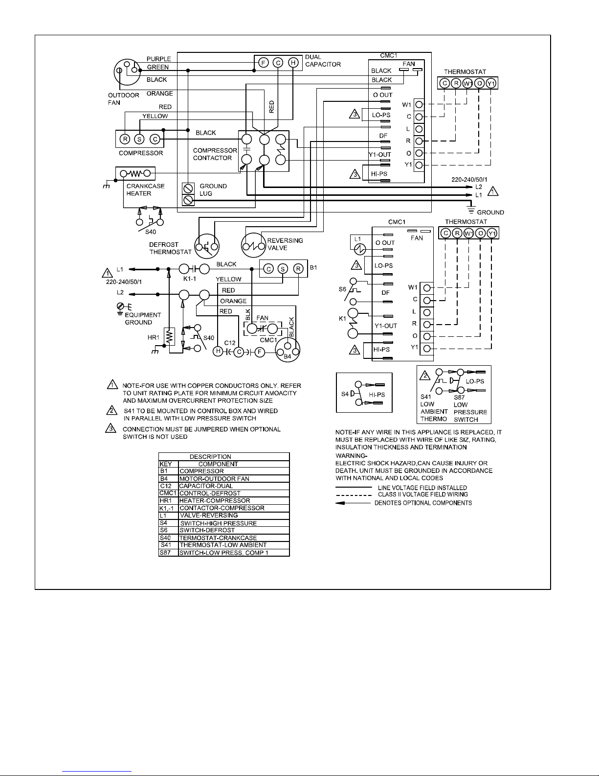
Figure 20. Typical Field Wiring Diagram T Voltage 220/240v (1PH) 50Hz
Page 32
 Loading...