

Page 1
1
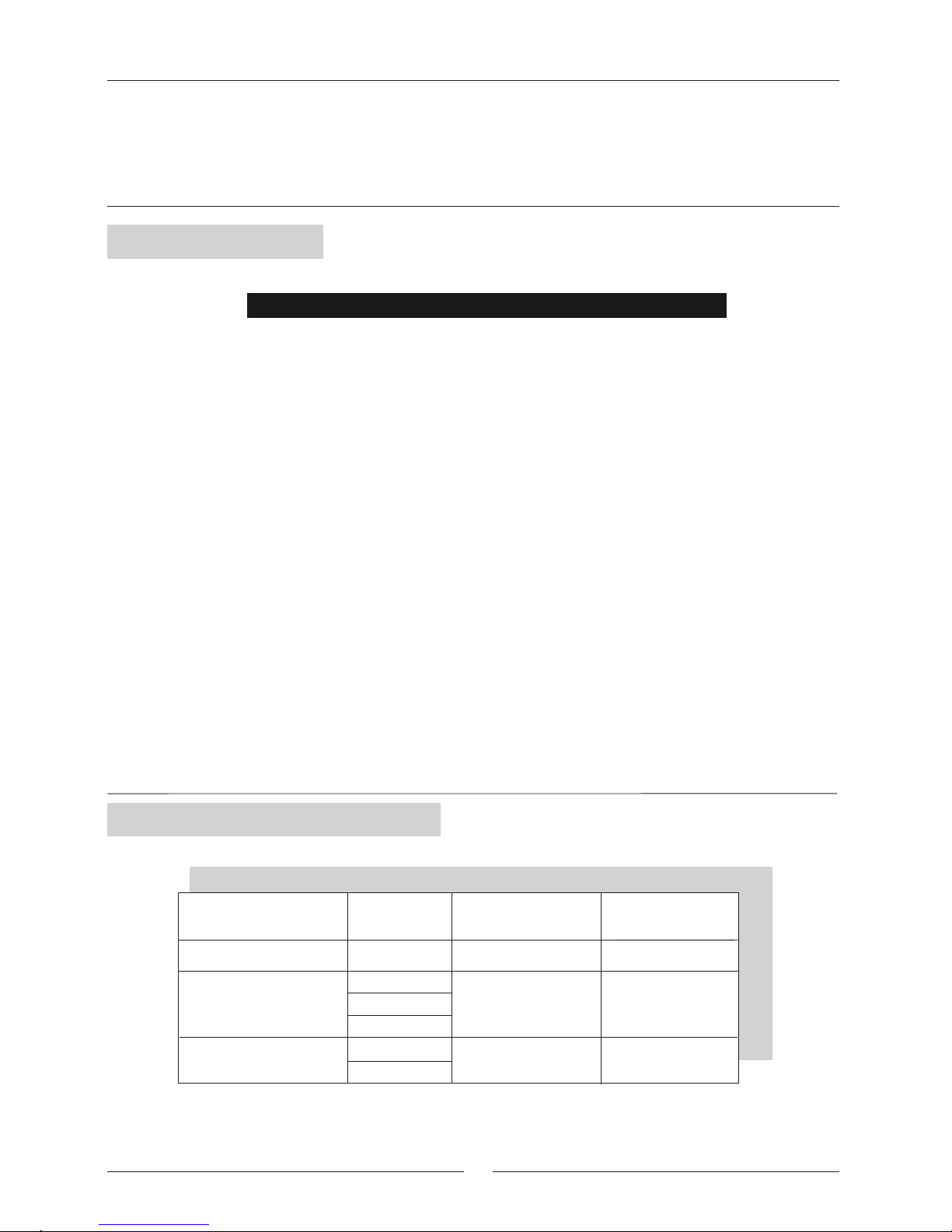
PRODUCT RANGE
UNIT V / Ph / 50 Hz
NOMINAL
CAPACITY W
10.700
13.600
3,18
3,82
400 V - 3Ph
230 V - 3Ph
400 V - 3Ph
NOMINAL
CONSUMPTION KW
230 V - 1Ph
230 V - 3Ph
230 V - 1PhSNE 2,8K
8.300 2,68
SNE 4K
SNE 3K
CONTENTS
• PRODUCT RANGE
• GENERAL DESCRIPTION
• SPECIFICATIONS
• ELECTRICAL CONNECTIONS
• FANS SPECIFICATIONS
• FUNCTION LIMITS
• TABLE OF CAPACITIES
• CONSUMPTION AND DROP WATER
• UNIT DIMENSIONS
• INSTALLATION
• MAINTENANCE OF THE UNIT
• OPTIONS
• POINTS TO KEEP IN MIND
• NOTES
PAGE
1
2
3
4
5
5
6
7
8
9
10
11
12
13-14
TABLE
Congratulations, you have made a wise choice the purchase of this product. This product
has been designed, assembled and supplied in one of our world class manufacturing
facilities and we feel that it will meet your expectations.
Page 2

GENERAL INFORMATION
The air conditioner, horizontal compact, water condensed type SNE, are specially design for small and average
installation, office, house etc..
On standard version cools, heats, dehumidifies, cleans and filter the air. The option of easily incorporating an
electric heater or hot water coil to be able to work as heating
The unit includes condenser plate, compact and
resistant made on inoxidable steel, specially selected
for this type of unit.
The cabinet is made of electrozinced steel with epoxy
painted finish and finished on polyester powder. Its
compact dimensions and features allow the unit to
be positioned in almost any location.
Internally the unit incorporate thermal acoustic
insulation to reduce sound level.
Made of copper tubing with aluminium swirl fins, they
are designed and specially dimensioned to obtain
the maximum output
The units include a centrifugal three speed motor fan,
with a motor directly fitted, with high performance on
air flow.
A polypropylene washable air filters are incorporated
in the unit they are easy accessible for maintenance
• Electrical heater mounted on fan discharge.
• Hot water coil.
• Presostatic valves regulating water flow
• Discharge plenum
• Admission plenum
• Digital thermostat programmable.
COMPRESSOR
CONDENSER
AIR FILTER
COOLING CIRCUIT
HEAT EXCHANGER
CABINET
FAN
OPTIONS
Made of welded dehumidifying copper tube with
access connections. Includes dehydrator filter, liquid
recipient expansion system and high and low
pressostat on all models
The electrical panel includes a printed board,
necessary for installation, and plate circuit board
ready to control the unit, which incorporates defrosting
timer thermostat. The power supply of the unit may
turn be off by a fusses block on the electrical box.
The function of the unit is controlled by cable
thermostat.
Digital remote controller by cable at 24V, digital
selector temperature which permit to choose the
following function:
• Selection ON/OFF
• Three functions mode: cool, heat and fan operating.
• Two options fan operating: AUTO (automatic) which
Select turn on and stop automatically fan mode
temperature. On mode ON the fan doesn´t stop
even when temperature is selected.
• Selector three steps fan.
REMOTE CONTROL
One compressor of the hermetically sealed type
cooled with internal thermal insulation. It is mounted
on vibration-absorbent blocks both on the inside and
outside, statically and dynamically balanced. In all
cases the compressors are acoustically isolated,
resulting in silent operation.
ELECTRICAL CIRCUIT
2
Page 3
3
m /h
3
230V /1Ph
230V / 400V 3Ph
NOMINAL ABSORBER POWER
Kw.
Compressor
Indoor fan
RUNNING CURRENT
A
Nominal running current
TOTAL
Kw.
Kw.
14,0
2,78
0,40
3,18
9,5/5,5
A
VOLTAGE
17,4
Maximum running current
18,0
16,0/10,0
23,0
A
91
78 / 39
90
Starting current
3,42
0,40
3,82
11,5/6,8
20,0/12,0
106 / 53
2,50
0,18
2,68
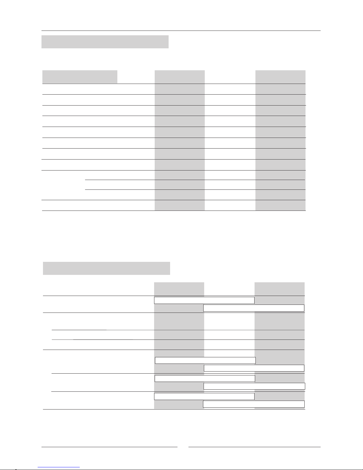
SPECIFICATIONS
Total cooling capacity
Nominal absorber power
Chilled water flow rate
Chilled water pressure drop
Hydraulic connections
Sound level (LP)(2)
Dimensions
Kw
l/h
W (*)
KPa
dB(A)
(mm)
H
Large
W
(mm)
(mm)
SNE 4K SNE 3K
Air flow (max./min.)
Pa
Available static power. (1)
Net weight
Kg
13.600
3,82
SNE 4K
80
SNE 3K SNE 2,8K
3000
16
120
53
1125
635
515
2050/1450
1" G
SNE 2,8K
10.700
3,18
100
2390
30
110
52
1125
635
515
2050/1100
3/4" G
8.300
2,68
120
1885
24
100
50
1125
635
515
1800/950
3/4" G
(*) Inlet air temperature: 27ºC DB / 19ºC WB
Inlet/Outlet water temperature: 30ºC / 35ºC
(1) With minimum air flow admissible
(2) Sound level has been tested at a distance of 2m from the unit.
UNIT
ELECTRICAL SPECIFICATIONS
Page 4
4
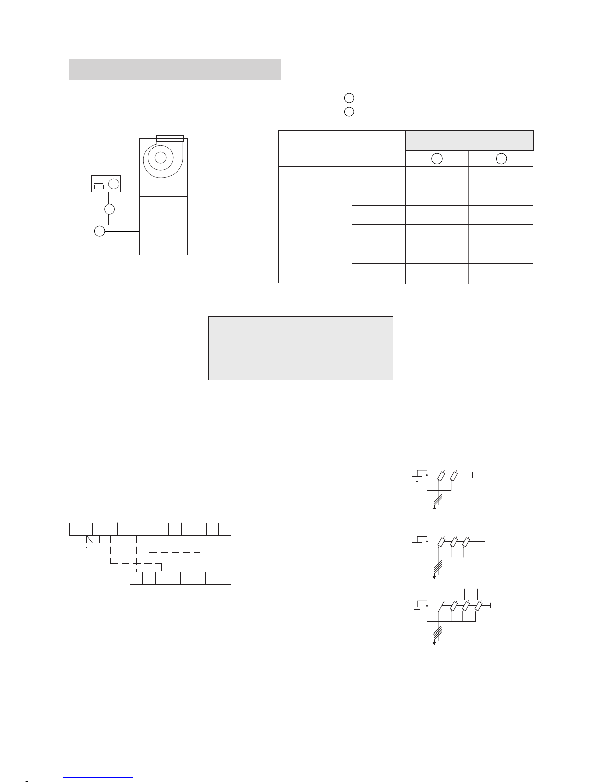
ELECTRICAL CONNECTIONS
E G HA B C D F
1 4 6 75 82 3 9 10 11
12 13
THERMOSTAT
PCB (Electronic)
Supply power
SNE 2,8K-3K-4K
400V/50HZ 3Ph + N + PE
FUSES
230V/50HZ 1Ph + N
FUSES
FUSES
230V/50HZ 3Ph
1
2
1
2
2
6 X 1,5mm
2
6 X 1,5mm
2
6 X 1,5mm
2
6 X 1,5mm
2
6 X 1,5mm
2
6 X 1,5mm
Power supply
Thermostat connections
1
2
2
3 X 4mm
2
4 X 6mm
2
5 X 4mm
2
3 X 4mm
2
4 X 4mm
2
5 X 2,5mm
MODEL
VOLTAGE
50Hz
SNE 2,8K
Nº OF CABLES X SECTION
230 V / 1Ph
SNE 3K
230 V / 1Ph
230 V / 3Ph
400 V / 3Ph
SNE 4K
230 V / 3Ph
400 V / 3Ph
ELECTRICAL WIRING DIAGRAM
FOR ELECTRICAL CONNECTION
REFER TO WIRING DIAGRAM IN
THE UNIT
Page 5
5
FAN SPECIFICATIONS
HIGH SPEED
AVERAGE SPEED
LOW SPEED
HIGH SPEED
AVERAGE SPEED
LOW SPEED
HIGH SPEED
AVERAGE SPEED
LOW SPEED
m /h
3
Unit leaves factory connected in AVERAGE and HIGH Speed.
m /h
3
Unit leaves factory connected in AVERAGE and LOW Speed
m /h
3
Unit leaves factory connected in HIGH and AVERAGE Speed.
80
100
120
1400
20 40
60
--- --- ---
---
SNE 2,8K
------ --- ---
1250 12251200
1150 ---1075 950 ---
1800 16501550
1425 97513001150 ---
80
100
120
1400
20 40
60
1840 17001575
1375
SNE 3K
---1275 --- ---
2000 18501700
1550 ---13751100 ---
2050 19251775
1625 ---14501250 ---
80
100
120
1400
20 40
60
1840 17001575
---
SNE 4K
------ --- ---
2000 18501700
1550 ------ --- ---
2050 19251775
1625 ---1450 --- ---
AIR FLOW
AVAILABLE STATIC PRESSURE
Pa.
AIR FLOW
AVAILABLE STATIC PRESSURE
Pa.
AIR FLOW
AVAILABLE STATIC PRESSURE
Pa.
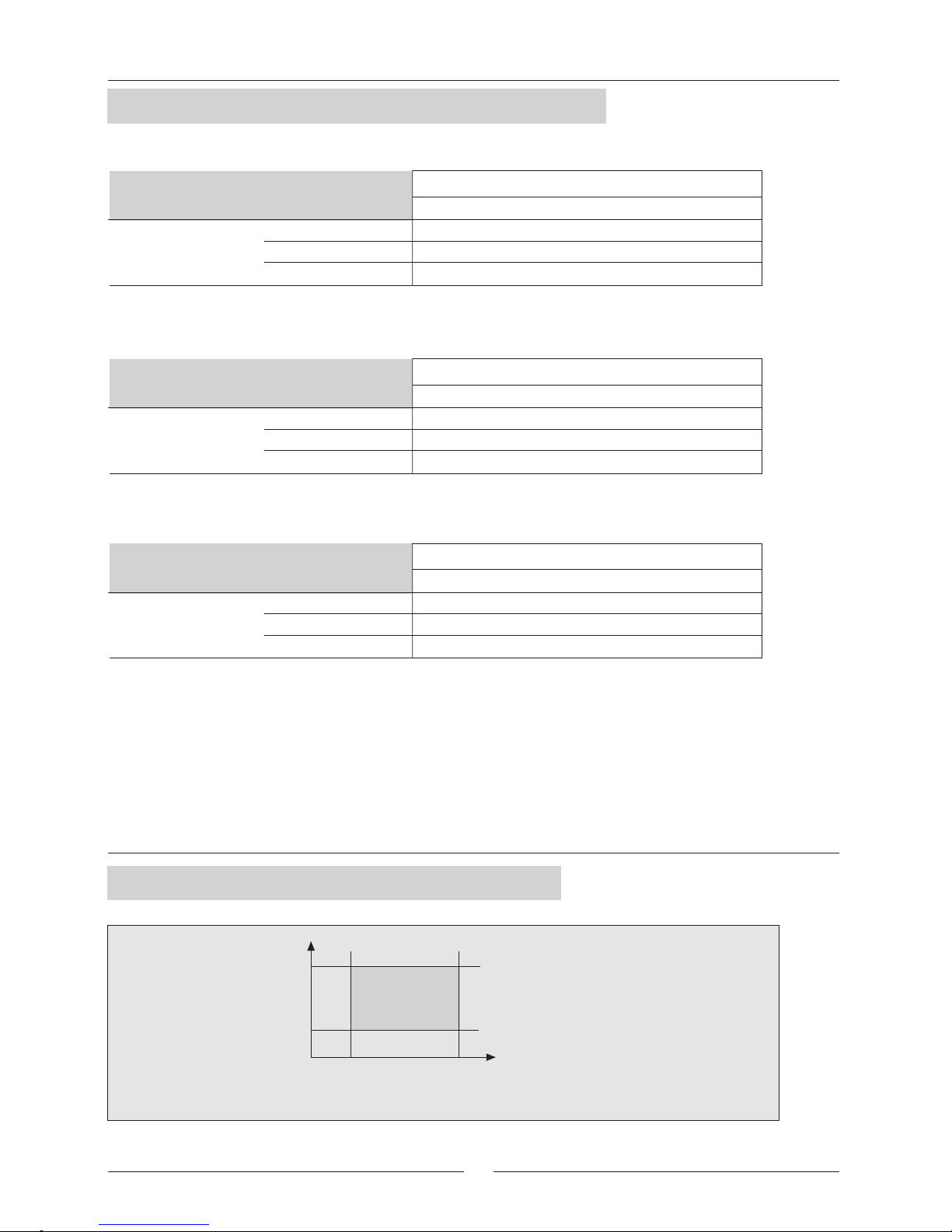
WB.: Temperature Wet bulb
DB.: Temperature Dry bulb
OPERATING LIMITS
-- /21ºC
32ºC / 38ºC
19°C / 14ºC 32°C / 23ºC
Inlet/outlet water
temperature to outdoor
section
Inlet air temperature to indoor section DB/ WB
Page 6

6
COOLING CAPACITY
INLET AIR
TEMPERATURE TO
INDOOR UNIT
COOLING
CAPACITY
IN kW
CONDENSING TEMPERATURE CONDENSING TEMPERATURE
INLET AIR
TEMPERATURE TO
INDOOR UNIT
COOLING
CAPACITY
IN kW
CONDENSING TEMPERATURE
DB: Dry Bulb
WB: Wet Bulb
TOTAL CAPACITY
SENSIBLE CAPACITY
COEFFICIENTS OF CORRECTION OF COOLING CAPACITY
AIR FLOW
MODELS SNE
2,8 3
1550 1700
AIR FLOW IN M3/H
SNE 2,8K
4
1700
SNE 3K
SNE 4K
MAX. NOMINAL MÍN. MAX. NOMINAL MIN. MÁX. NOMINAL MIN.
1
1
1,02
1,06
0,90
0,81
1
1
1,03
1,08
0,90
0,82
1
1
1,03
1,07
0,98
0,96
Data based on the following air flow:
Data of cooling capacity rated on tables are calculated for nominal air flow, for minimum /maximum air flow, you
must follow the following table
7,53
5,52
8,17
5,93
8,85
6,33
9,60
6,36
10,39
6,73
45°C 50°C40°C
35°C
7,21
5,36
7,83
5,77
8,49
6,16
9,20
6,19
9,97
6,57
6,57
5,04
7,13
5,44
7,74
5,83
8,40
5,86
9,10
6,23
6,89
5,20
7,48
5,61
8,12
6,00
8,80
6,03
9,54
6,40
55°C
6,24
4,88
6,78
5,28
7,36
5,67
7,99
5,69
8,65
6,05
21°C DB
15°C WB
24°C DB
17°C WB
27°C DB
19°C WB
29°C DB
21°C WB
32°C DB
23°C WB
TOTAL
SENSIBLE
TOTAL
SENSIBLE
TOTAL
SENSIBLE
TOTAL
SENSIBLE
TOTAL
SENSIBLE
7,84
5,68
8,50
6,09
9,21
6,49
9,98
6,53
10,81
6,90
30°C
9,80
7,13
10,65
7,66
11,58
8,18
12,58
8,24
13,66
8,74
45°C 50°C40°C
35°C
9,40
6,93
10,23
7,46
11,13
7,97
12,10
8,03
13,14
8,52
8,61
6,53
9,38
7,05
10,21
7,56
11,11
7,62
12,08
8,10
9,01
6,73
9,81
7,26
10,67
7,77
11,61
7,83
12,62
8,31
55°C
8,20
6,33
8,94
6,85
9,74
7,36
10,61
7,41
11,54
7,89
10,19
7,33
11,07
7,86
12,02
8,38
13,06
8,45
14,18
8,95
30°C
12,36
8,49
13,41
9,05
14,54
9,60
15,77
9,69
17,08
10,21
45°C 50°C40°C
35°C
11,84
8,20
12,85
8,76
13,95
9,31
15,13
9,39
16,40
9,90
10,82
7,66
11,76
8,21
12,78
8,74
13,87
8,81
15,04
9,31
11,33
7,92
12,30
8,48
13,36
9,02
14,50
9,10
15,72
9,60
55°C
10,32
7,40
11,23
7,94
12,20
8,47
13,25
8,53
14,37
9,03
21°C DB
15°C WB
24°C DB
17°C WB
27°C DB
19°C WB
29°C DB
21°C WB
32°C DB
23°C WB
TOTAL
SENSIBLE
TOTAL
SENSIBLE
TOTAL
SENSIBLE
TOTAL
SENSIBLE
TOTAL
SENSIBLE
12,89
8,78
13,98
9,35
15,14
9,91
16,41
10,00
17,77
10,52
30°C
SNE 2,8K
SNE 3K
Nominal capacity established on following conditions:
• Air inlet temperature : 27ºC DB/19ºC WB
• Inlet/outlet water temperature: 30ºC/35ºC
• Condensing Temperature between 40 and 45ºC depending on models
SNE 4K
Page 7

7
1000 1500 2000 2500 3000 3500 4000 4500 5000
0
10
20
30
40
50
60
70
80
90
100
WATER FLOW (L / H)
WATER PRESSURE DROP Kpa
10 15 4520 25 30
TABLE OF WATER CONSUMPTION ON UNITS SNE (L/H) (*)
DIFFERENCES BETWEEN:
CONDENSATION TEMPERATURE AND INLET WATER TEMPERATURE (ºC)
35 40
( * ) Inlet air
temperature
27ºCWB / 19ºC DB
SNE 2,8K
3300 1220 235740 520 400 325 270
SNE 3K
4160 1545 300945 670 515 420 350
SNE 4K
4550 1690 3301030 730 560 460 385
COEFFICIENTS FOR DIFFERENT AIR INLET TEMPERATURE.
Coefficients of water consumption
32/23
1,14
21/15
0,88
24/17
0,93
AIR INDOOR TEMPERATURE (WB/DB)
27/19
1
29/21
1,07
CONSUMPTION AND WATER PRESSURE DROP
UNIT
For different air inlet temperature multiply the
consumption by the coefficent of this table.
Normally, the water condense is used across a cooling tower with water temperature around 30ºC, and water
flow avilable to work the unit with condensation temperature between 40 and 45ºC.
You are able not to use a cooling tower when the unit is near a river etc.. with enough flow and enough quality of
the water. The use of the water must be used always across a previous Analysis of water.
If the water inlet temperature is below 20ºC, It is then necessary to use a regulation valve (Option) to maintain
condensing temperature value between 40 and 45 ºC.
Depending inlet water temperature and condensation temperature needed you will be able to calculate water
consumption following the table below.
WATER PRESSURE DROP
SNE 4K
SNE 2,8K - 3K
Page 8

8
DIMENSIONS
515
635
540
529
1125
167,5
300
167,5
264
237
14
4xFILTERS OF 300x270
243,5
63,5
607
607
1
2
3
8
4
7
8
8
12
13
11
172
515
317
270
635
6
6
Possibility to change the situation of the electrical box tacking
out the screw of the tape as shown in the figure, for an easy
access depending on the installation of the unit.
Factory position of
the electrical box
Option position of the electrical box
(To change by the installer)
DETAIL A
5
6
9
DETAIL A
1
2
3
4
5
6
7
8
9
10
11
12
13
MOTOR FAN
COMPRESSOR
COIL
4 x AIR FILTER
WATER EXCHANGER
ELECTRICAL BOX (2 possible positions)
DRAIN PAN
INLET/OUTLET WATER (3 possible access)
POWER SUPPLY
MAIN SWITCH
DRAINAGE TUBE O 16mm outdoor
PLENUM OF ADMISSION (OPTION)
PLENUM OF DISCHARGE (OPTION)
Page 9

9
Prior to install the equipment make sure of the following points:
• Leave enough space for access to air supply, water section, power supply and outlet condense.
• The water section must have the correspondant valves.
• Easy extraction of the air filter.
• Easy access to lateral panel for easy accessibility to all services of the unit.
• Unit must be mounted with springs.
• The electrical section must be done following legal normative
• Check that the tension is the same as installation place.
• Check the water condense quality, across analysis.
• Keep in mind water inlet temperature of the unit. Temperature below 20ºC you will need a water regulation
pressostatic valve ( element as option) to maintain condensation temperature value between 40 and 45ºC.
• Depending on water entry temperature, you have to calculate the water flow following the consumption table.
• Check that air flow needed correspond for duct installation.
• Keep in mind power supply for maximum consumption for each unit.
• All installation must be carried out by qualified personnel
• Make sure that the unit is completely disconnected from the power supply before carrying out any type of work
on the unit.
Hydraulic circuit:
• Air flow:
• All models include three fan speed motor fan.
• Make the motor fan connections for the fan speed required to adecuate the air flow neded for the
installation
• Drainage tube:
• Use the flexible tube connected to the tray as a drainage tube.
Cause a siphon with this tube in order to avoid the inlet of scents from the installation to the unit.
• Make sure that the water connections are correct, inlet water (down side), outlet water (upper side)
• Fit a water filter in the outlet water connection, the step of the mesh should not be less than 0.5mm, wich
avoid welded and dirty get to the unit.
• If quality of water is not good, may be neccesary to install a decalcified
• Install cut off valves at inlet and outlet water connections, because of in case of repairs, the hydraulic
circuit can be independent.
• Install an adecuate water pump, and all the elements necessaries for the installation.
INSTALLATION
INSTALLATION
PRE-INSTALLATION
Page 10

10
• The unit under supply, have rotating objects and high temperature into the pipe. Make sure to turn off electrically
the unit before to access for maintenance or revision.
• Air filter: Clean the filter (maximum each 6 months), but the clean of the filter depend on the ambient where the
units is working.
• Water filter: Realise a clean of the filter.
• Security elements: The unit include electrical elements of security( Internal thermal protection on the compressor
and motor fan, external thermal protection on the compressor and motor three phase) and cooling elements of
security like high and low pressostat pressure with electrical rearm. If limits of function of the unit is out of conditions
of work, some protections will be display.
LOCALISATION OF PROBLEMS
PROBLEMS CAUSES
SERVICE AND MAINTENANCE
• Cut low pressure (Electrical rearm) (*)
• Cooling capacity low.
• Freeze on coil
• Air in temperature very low
• Defect on refrigerant charge.
Test that the refrigerant is correct.
• Air filter dirty
• low air flow.
• Water temperature is too low
• High water temperature
• Low air flow
• Cut high pressure (Electrical ream) (*)
• High consumption
• Thermal compressor protection cut
(*) Rearm electrically the unit turning off/on, after repair the cause which produce a cut on high and low pressure.
Page 11

6 Kw 1 Step
7,5 Kw 1 Step
11
Electrical box
•The electrical should be install into the impulsion fan of the unit.
• Fix the screws following the figure.
• Take out the knock out, and take the electrical supply of the
electrical heater to the electrical box of the unit.
Fix both plenums with the screws supplied
ADMISSION PLENUM
DISCHARGE PLENUM
ELECTRICAL
HEATER
Knock out
electrical heater
power supply
HOT WATER
COIL
INSTALLATION
INSTALLATION
ELECTRICAL HEATER TECHNICAL DATA
HOT WATER COIL 1 ROW TECHNICAL DATA
Use discharge plenum if you do not use duct on the discharge.
This plenum includes a grille with orientable lame for a correct distribution of the air.
Use the admission plenum if you are going to use duct of
aspiration air or hot water coil. The superior part is detachable
to access and clean air filter of the unit.
PLENUM
This optional kit included a hot water coil and an admission plenum.
• Install the admission plenum with the screw supplied at the discharge of the unit.
• Screw the hot water coil to the discharge plenum as figure shows.
The hot water coil is symmetrical, the water connections could be located, to the right or left.
OPTIONS
CAPACITY IN KW FOR FLOW OF 500 L/H .
Power
Voltages
DISCHARGE PLENUM
ADMISSION PLENUM
SNE 2,8K - 3K - 4K
60
50
40
8,25 6,60
9,90
SNE
2,8K - 3K - 4K
230V / 1Ph -50Hz
230 V /400 V 3Ph -50Hz
230 V /400 V 3Ph -50Hz
DROP PRESSURE AIR = 10 Pa.
DROP PRESSURE WATER= 15 K Pa
DATA CALCULATED FOR AN AIR FLOW OF = 1700 m /h
3
DIFERENCE TEMPERATURE BETWEEN WATER IN
AND AIR IN INTO THE BATTERIE (ºC)
Page 12

Water in
CONDENSER
12
Water out
UNIT
VASTAGE OF
REGULATION
Connect to plug
high pressure
If water inlet temperature is below 20ºC we recommend to maintain level condensation temperature in (40 a 45ºC)
FUNCTION
The presostatic valve maintain some values of the condensation pressure regulating the water flow which enter
into the condenser.
When the condensation pressure is up, the valve open and water enter. and when pressure is low the valve close.
PRESOSTATIC VALVES
REGULATION PRESOSTATIC VALVES
• Connect a manometer of high pressure (30 bar) near the refrigerating circuit of the unit.
• Turn over the vastage in the head of the valve( right the valve open, left the valve close) regulating the water flow
which enter into the unit.
• You must leave the unit working during 10 minutes and see the indication of the manometer. If the condensation
pressure temperature is aproximately. 45ºC the valve is correctly regulated. If not restart the regulation described
before.
• Install the kit at the outlet water side of the condenser
• Keep in mind the row indicated in the valve.
• Connect the capillary tube of the valve to the plug of high pressure in the pipe of the unit.
OPTIONS
Page 13

13
POINTS TO KEEP IN MIND
Before attempting to perform any
service or maintenance on unit, turn off
the electrical power, and check that the
fan has stopped.
All technical data contained in these operating instructions including the diagrams and technical description
remains the property of Lennox and may not be used (except for the purpose of familiarising the user with the
equipment), reproduced, photocopied, transferred or transmitted to third parties without prior written authorisation
from Lennox.
The data published in the operating instructions is based on the latest information available. We reserve the right
to make modifications without notice.
We reserve the right to modify our products without obligation to modify previously supplied goods.
These operating instructions contain useful and important information for the smooth operation and maintenance
of your equipment.
The instructions also includes guideliness on how to avoid accidents and serious damage before commissioning
the equipment and during its operation and how to ensure smooth and fault-free operation. Read the operating
instructions carefully before starting the equipment, familiarise yourself with the equipment and handling of the
installation and carefully follow the instructions. It is very important to be properly trained in handling the equipment.
These operating instructions must be kept in a safe near the equipment.
Like most equipment, the unit requieres regular maintenance. This section concerns the maintenance personnel
and management.
If you have any queries or would like to receive futher information on any aspect relating to your equipement, do
not hesitate to contact us.
standard guildness to lennox equipement
Check the filter and make
sure its blocked with dust or
dirt.
FILTER CLEANING
If the filter is dirty, wash it in a bowl with
neutral saop and watre, drying it in the
shade before inserting it in the unit.
ATTENTION
ABRASIVE
SURFACE
LOW
TEMP
HIGH
TEMP.
RISK OF INJURY
MOVING OBJECTS
ELECT.
VOLTA
RISK OF INJURTY
WITH ROTATING
Page 14

14
NOTAS
Page 15

SNE-K-
OPERATION, SERVICE AND
INSTALLATION MANUAL
Page 16

GREAT BRITAIN,
IRELAND:
BELGIUM :
CZECH REPUBLIC :
FRANCE :
GERMANY:
NETHERLANDS :
POLAND :
PORTUGAL :
RUSSIA :
SLOVAKIA :
SPAIN:
UKRAINE :
OTHER EUROPEAN COUNTRIES,
AFRICA,
MIDDLE-EAST :
COD:
LENNOX INDUSTRIES LTD
tél. : + 44 1604 59 9400
fax : + 44 1604 594200
e-mail : marketing lennoxind.com
LENNOX BENELUX N.V./S.A.
tél. : + 32 3 633 30 45
fax : + 32 3 633 00 89
e-mail : inf.beo lennoxbenelux.com
JANKA RADOTIN AS
tél. : + 420 2 510 88 111
fax : + 420 2 579 10 393
e-mail : janka janka.cz
LENNOX FRANCE
tél. : + 33 1 60 17 88 88
fax : + 33 1 60 17 86 58
e-mail : accueil lennoxfrance.com
LENNOX DEUTSCHLAND Gmbh
tél. : + 49 69 42 0979 0
fax : + 49 69 42 0979 40
e-mail : info lennoxdeutschland.com
LENNOX BENELUX B.V.
tél. : + 31 33 2471 800
fax : + 31 33 2459 220
e-mail : info lennoxbenelux.com
LENNOX POLSKA SP z o.o.
tél. : + 48 22 832 26 61
fax : + 48 22 832 26 62
e-mail : lennoxpolska inetia.pl
LENNOX CLIMATIZAÇAO LDA.
tél. : + 351 22 999 84 60
fax : + 351 22 999 84 68
e-mail : marketing lennoxportugal.com
LENNOX DISTRIBUTION MOSCOW
tél. : + 7 095 246 07 46
fax : + 7 502 933 29 55
e-mail : lennox.dist.moscow co.ru
LENNOX SLOVAKIA
tél. : + 421 7 44 88 92 16
fax : + 421 7 44 88 16 88
LENNOX REFAC S.A.
tél. : + 34 902 400 405
fax : + 34 91 542 84 04
e-mail : marketing lennox-refac.com
LENNOX DISTRIBUTION KIEV
tél. : + 380 44 213 14 21
fax : + 380 44 213 14 21
e-mail : jankauk uct..kiev.ua
LENNOX DISTRIBUTION
tél. : + 33 4 72 23 20 14
fax : + 33 4 72 23 20 28
e-mail :marketing lennoxdist..com
w w w . L e n n o x . c o m
 Loading...