

Lennox SLP98UHV, SLP98UH070V36B, SLP98UH090V36C, SLP98UH090V48C, SLP98UH090V60C Unit Information
...Page 1
Service Literature
Corp. 1029−L7
SLP98UHV SERIES UNITS
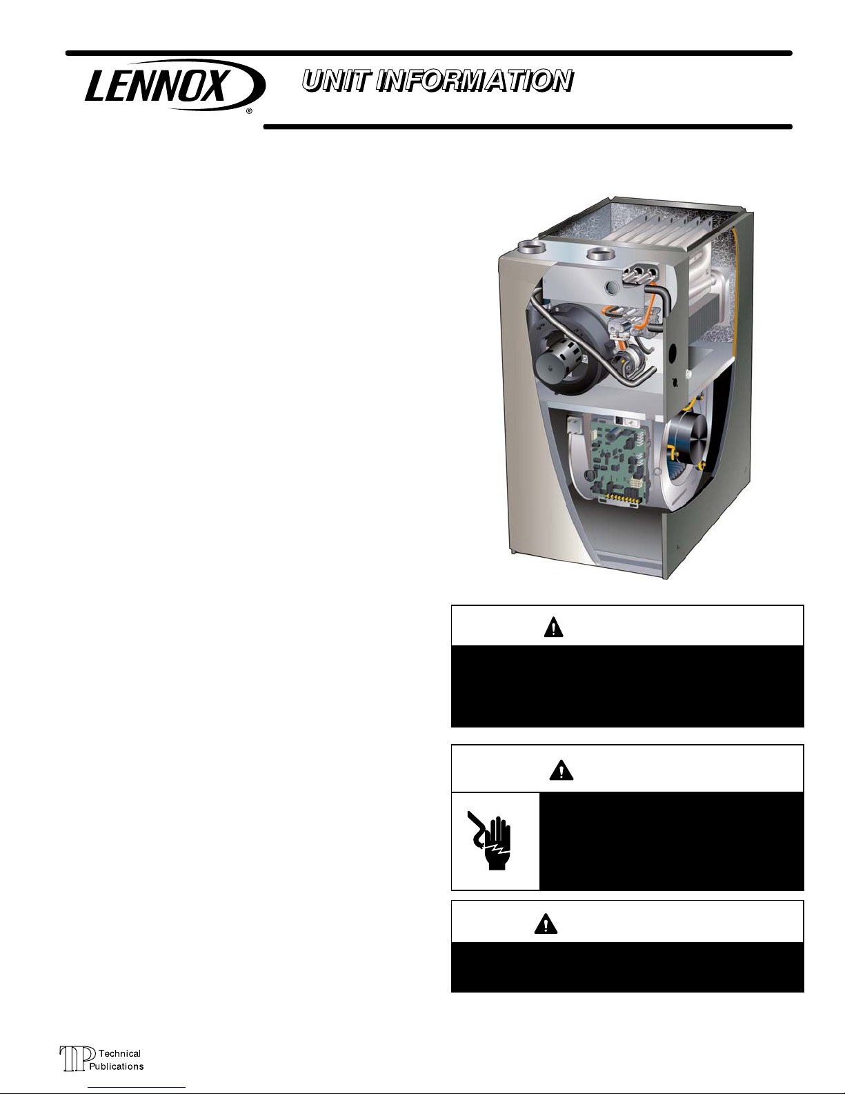
SLP98UHV series units are high−efficiency upflow, horizontal right and left) gas furnaces equipped with variable capacity gas valve, variable speed combustion air inducer and
variable speed indoor blower motor. All models are designed only for direct vent (dual pipe) venting system.
SLP98UHV units are available in heating capacities from
66,000 to 132,000 Btuh (19.3 to 38.6 kW) and cooling applications from 2 to 5 tons (7.0 kW to 17.5 kW). Refer to Engineering Handbook for proper sizing.
Units are factory−equipped for use with natural gas. Kits are
available for conversion to LPG operation. SLP98UHV mod-
®
els include a SureLight
that can be used with Lennox icomfort Touch thermostat as
part of a communicating comfort system. All SLP98UHV
units meet the California Nitrogen Oxides (NOx) Standards
and California Seasonal Efficiency requirements.
variable capacity integrated control
SLP98UHV
All specifications in this manual are subject to change. Procedures outlined in this manual are presented as recommendations only and do not supersede or replace local or
state codes. In the absence of local or state codes, the
guidelines and procedures outlined in this manual (except
where noted) are recommendations only and do not constitute code.
TABLE OF CONTENTS
Specifications Page 2. . . . . . . . . . . . . . . . . . . . . . . . . . . . .
Optional Accessories Page 3. . . . . . . . . . . . . . . . . . . . . .
Blower Data Page 4. . . . . . . . . . . . . . . . . . . . . . . . . . . . . .
I Unit Components Page 14. . . . . . . . . . . . . . . . . . . . . . . .
II Icomfort Touch Thermostat Page 37. . . . . . . . . . . .
III Placement and Installation Page 39. . . . . . . . . . . . . . .
IV Start Up Page 53. . . . . . . . . . . . . . . . . . . . . . . . . . . . . .
V Heating System Service Checks Page 54. . . . . . . . . .
VI Typical Operating Characteristics Page 56. . . . . . . . .
VII Maintenance Page 57. . . . . . . . . . . . . . . . . . . . . . . . . .
VIII Wiring and Sequence of Operation Page 59. . . . . .
XI Field Wiring Page 67. . . . . . . . . . . . . . . . . . . . . . . . . . .
WARNING
Improper installation, adjustment, alteration, service
or maintenance can cause property damage, personal injury or loss of life. Installation and service must
be performed by a licensed professional installer (or
equivalent), service agency or the gas supplier.
WARNING
Electric shock hazard. Can cause injury
or death. Before attempting to perform
any service or maintenance, turn the
electrical power to unit OFF at disconnect switch(es). Unit may have multiple
power supplies.
WARNING
Sharp edges.
Be careful when servicing unit to avoid sharp edges
which may result in personal injury.
Page 1
© 2010 Lennox Industries Inc.
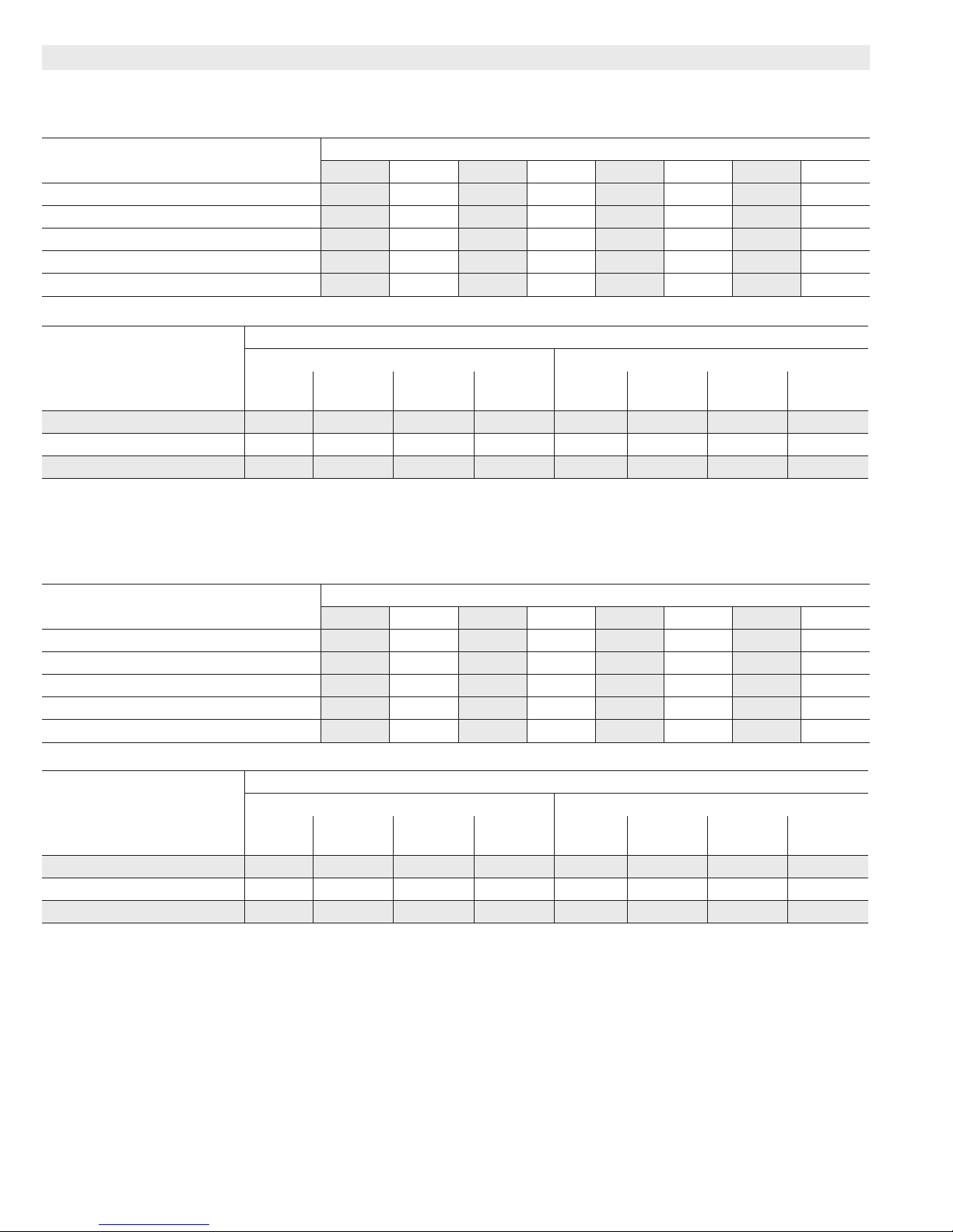
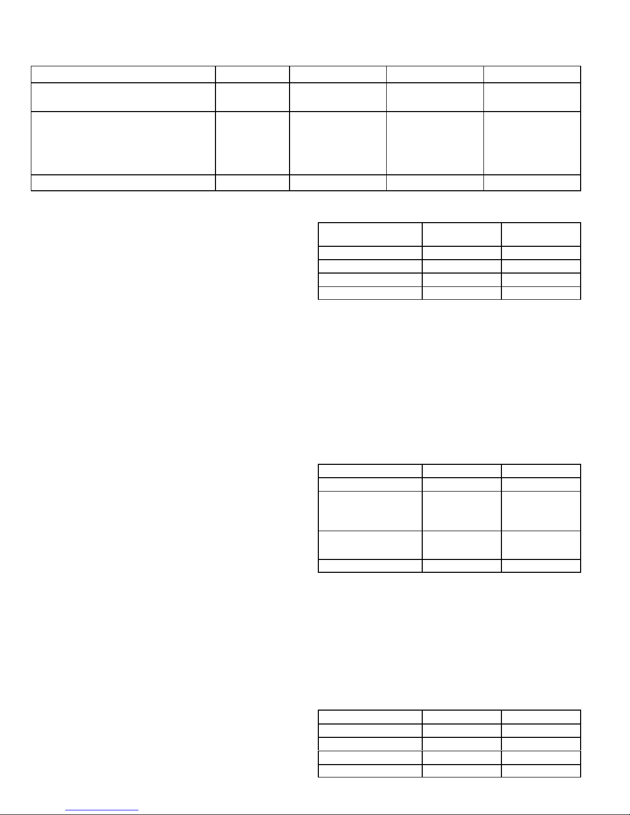
Page 2
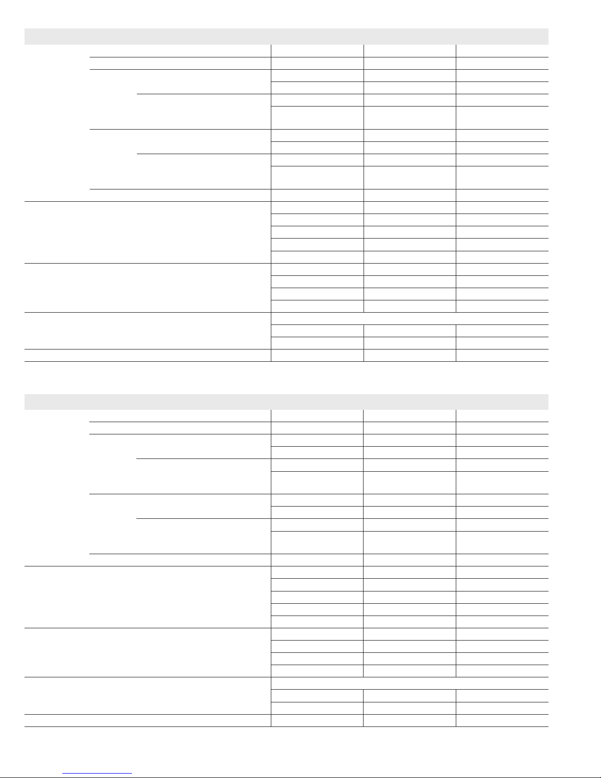
SPECIFICATIONS
Gas
Heating
Performance
Maximum Input - Btuh 66,000 88,000 88,000
Temperature rise range - °F 50 - 80 60 - 90 50 - 80
Gas Manifold Pressure (in. w.g.)
Nat. Gas / LPG/Propane
Minimum Input - Btuh 23,000 31,000 31,000
Temperature rise range - °F 35 - 65 35 - 65 35 - 65
Gas Manifold Pressure (in. w.g.)
Nat. Gas / LPG/Propane
High static - in. w.g. 0.8 0.8 0.8
Connections
in.
Condensate Drain Trap (PVC pipe) - i.d. 1/2 1/2 1/2
Intake / Exhaust Pipe (PVC) 2 / 2 2 / 2 2 / 2
with eld supplied (PVC coupling) - o.d. 1/2 slip x 1/2 NPT 1/2 slip x 1/2 NPT 1/2 slip x 1/2 NPT
hose with hose clamp - i.d. x o.d. 1 x 1-1/4 1 x 1-1/4 1 x 1-1/4
Gas pipe size IPS 1/2 1/2 1/2
Indoor
Wheel nominal diameter x width - in. 10 x 9 10 x 9 11 x 11
Blower
Tons of add-on cooling 2 - 3 2 - 3.5 2.5 - 4
Air Volume Range - cfm 339 - 1365 520 - 1360 528 - 1770
Electrical
Data
Voltage (Maximum Amps) 120 volts - 60 hertz - 1 phase
Blower motor full load amps 7.7 7.7 10.1
Maximum overcurrent protection 15 15 15
Shipping Data lbs. - 1 package 138 155 165
NOTE - Filters and provisions for mounting are not furnished and must be eld provided.
1
Annual Fuel Utilization Efciency based on DOE test procedures and according to FTC labeling regulations. Isolated combustion system rating for non-weatherized
furnaces.
Model No. SLP98UH070V36B SLP98UH090V36C SLP98UH090V48C
1
AFUE 97.0% 98.0% 97.5%
Output - Btuh 64,000 85,000 85,000
3.5 / 10.0 3.5 / 10.0 3.5 / 10.0
Output - Btuh 22,000 30,000 30,000
0.5 / 1.5 0.5 / 1.5 0.5 / 1.5
Motor output - hp 1/2 1/2 3/4
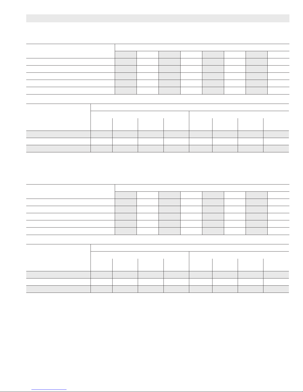
SPECIFICATIONS
Gas
Heating
Performance
Maximum Input - Btuh 88,000 110,000 132,000
Temperature rise range - °F 50 - 80 50 - 80 55 - 85
Gas Manifold Pressure (in. w.g.)
Nat. Gas / LPG/Propane
Minimum Input - Btuh 31,000 39,000 46,000
Temperature rise range - °F 35 - 65 35 - 65 35 - 65
Gas Manifold Pressure (in. w.g.)
Nat. Gas / LPG/Propane
High static - in. w.g. 0.8 0.8 0.8
Connections
in.
Condensate Drain Trap (PVC pipe) - i.d. 1/2 1/2 1/2
Intake / Exhaust Pipe (PVC) 2 / 2 2 / 2 2 / 2
with eld supplied (PVC coupling) - o.d. 1/2 slip x 1/2 NPT 1/2 slip x 1/2 NPT 1/2 slip x 1/2 NPT
hose with hose clamp - i.d. x o.d. 1 x 1-1/4 1 x 1-1/4 1 x 1-1/4
Gas pipe size IPS 1/2 1/2 1/2
Indoor
Wheel nominal diameter x width - in. 11 x 11 11 x 11 11 x 11
Blower
Tons of add-on cooling 3 - 5 3 - 5 3.5 - 5
Air Volume Range - cfm 375 - 2195 554 - 2125 634 - 2190
Electrical
Data
Voltage (Maximum Amps) 120 volts - 60 hertz - 1 phase
Blower motor full load amps 12.8 12.8 12.8
Maximum overcurrent protection 20 20 20
Shipping Data lbs. - 1 package 165 175 190
NOTE - Filters and provisions for mounting are not furnished and must be eld provided.
1
Annual Fuel Utilization Efciency based on DOE test procedures and according to FTC labeling regulations. Isolated combustion system rating for non-weatherized
furnaces.
Model No. SLP98UH090V60C SLP98UH110V60C SLP98UH135V60D
1
AFUE 98.2% 97.5% 97.5%
Output - Btuh 85,000 106,000 126,000
3.5 / 10.0 3.5 / 10.0 3.5 / 10.0
Output - Btuh 30,000 38,000 45,000
0.5 / 1.5 0.5 / 1.5 0.5 / 1.5
Motor output - hp 1 1 1
Page 2
Page 3
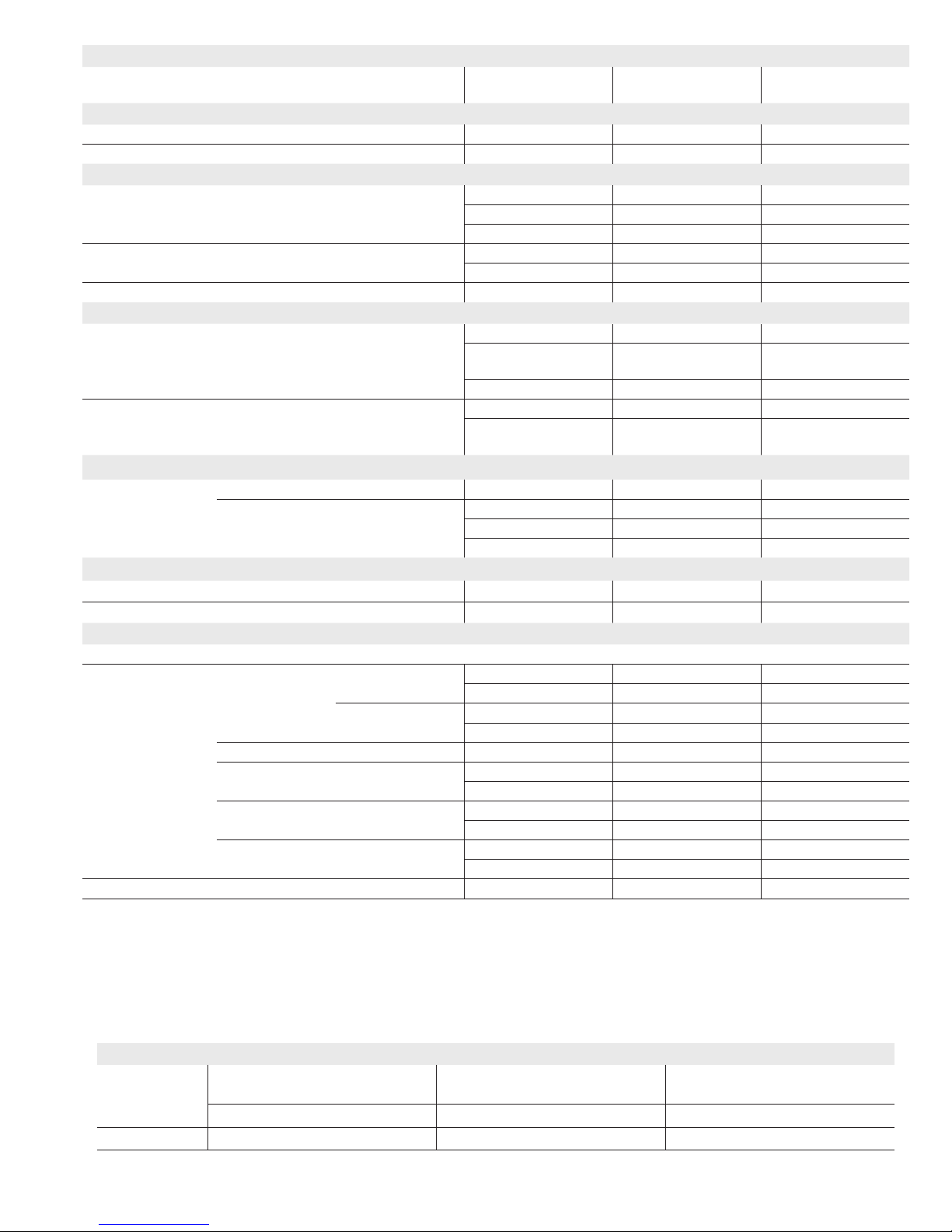
OPTIONAL ACCESSORIES - MUST BE ORDERED EXTRA
“B” Width
Models
CABINET ACCESSORIES
Horizontal Suspension Kit - Horizontal only 51W10 51W10 51W10
Return Air Base - Upow only 50W98 50W99 51W00
CONDENSATE DRAIN KITS
Condensate Drain Heat Cable 6 ft. 26K68 26K68 26K68
24 ft. 26K69 26K69 26K69
50 ft. 26K70 26K70 26K70
Heat Cable Tape Fiberglass - 1/2 in. x 66 ft. 36G53 36G53 36G53
Aluminum foil - 2 in. x 60 ft. 16P89 16P89 16P89
Crawl Space Vent Drain Kit 51W18 51W18 51W18
CONTROLS
icomfort Touch™ Communicating Thermostat 49W95 49W95 49W95
1
Remote Outdoor Temperature Sensor
X2658 X2658 X2658
(for dual fuel and Humiditrol®)
2
Discharge Temperature Sensor 88K38 88K38 88K38
ComfortSense
3
Remote Outdoor Temperature Sensor
®
7000 Thermostat Y2081 Y2081 Y2081
X2658 X2658 X2658
(for dual fuel and Humiditrol)
FILTER KITS
4
Air Filter and
Rack Kit
Horizontal (end) Size of lter - in. 87L96 - 18 x 25 x 1 87L97 - 20 x 25 x 1 87L98 - 25 x 25 x 1
Side Return Single 44J22 44J22 44J22
Ten Pack 66K63 66K63 66K63
Size of lter - in. 16 x 25 x 1 16 x 25 x 1 16 x 25 x 1
NIGHT SERVICE KITS
Night Service Kit 65W78 65W78 65W78
Safety Night Service Kit 51W05 51W05 51W05
TERMINATION KITS
Direct Vent Applications Only. See Installation Instructions for specic venting information.
Termination Kits Concentric US - 2 in. 71M80 69M29 - - -
3 in. - - - 60L46 60L46
Canada - 2 in. 44W92 44W92 - - -
3 in. - - - 44W93 44W93
Flush-Mount 2, 2-1/2 or 3 in. 51W11 51W11 51W11
Wall - Close
Couple
Wall - Close
Couple WTK
Roof 2 in. 15F75 15F75 - - -
Wall Ring Kit 2 in. 15F74 15F74 - - -
Roof Termination Flashing Kit (2 ashings) 2 in. 44J41 44J41 44J41
1
Remote Outdoor Sensor may be used with an icomfort™-enabled outdoor unit for a secondary (alternate) sensor reading. Sensor may also be used with a
conventional outdoor unit.
2
Optional for service diagnostics.
3
Remote Outdoor Temperature Sensor for ComfortSense 7000 Thermostat must be connected directly to the thermostat, Do not connect it to the icomfort™ control board.
4
Cleanable polyurethane frame type lter.
NOTE - Termination Kits 44W92, 44W93, 30G28, 81J20 are certied to ULC S636 standard for use in Canada only.
US - 2 in. 22G44 - - - - - -
3 in. 44J40 44J40 44J40
Canada - 2 in. 30G28 - - - - - -
3 in. 81J20 81J20 81J20
“C” Width
Models
“D” Width
Models
Input High Altitude
Pressure Switch Kit
7501 - 10,000 ft. 0 - 10,000 ft. 0 - 10,000 ft.
All models 73W89 65W77 70W87
GAS HEAT ACCESSORIES
Natural Gas to
LPG/Propane Kit
Page 3
LPG/Propane to
Natural Gas Kit
Page 4

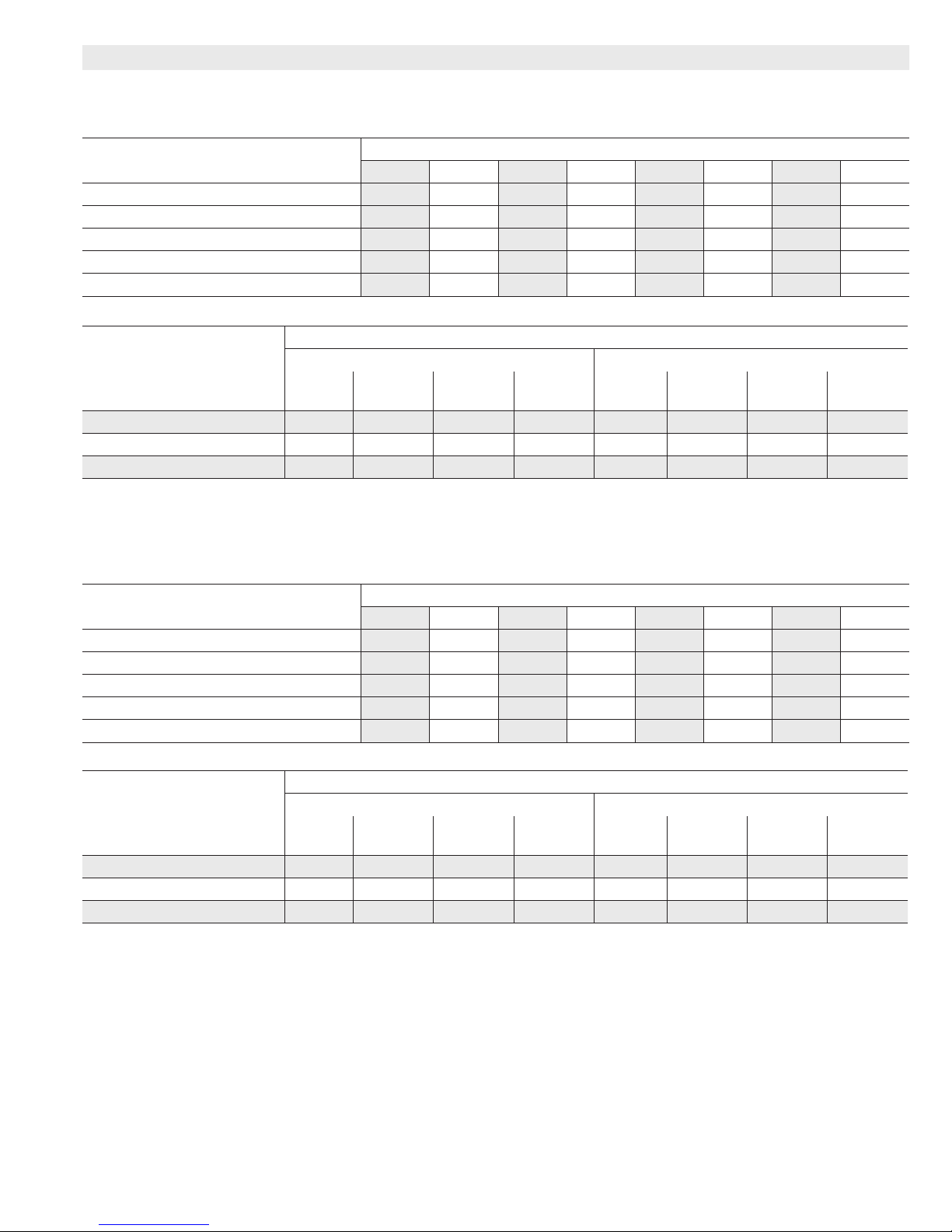
BLOWER DATA
SLP98UH070V36B BLOWER PERFORMANCE (less lter)
BOTTOM RETURN AIR
HEATING BLOWER PERFORMANCE
Heating Adjust CFM Selections
35% 40% 50% 60% 70% 80% 90% 100%
Increase (+15%) Heat CFM 489 538 636 735 833 931 1030 1128
Increase (+7.5%) Heat CFM 450 496 588 680 772 864 956 1048
Default Heat CFM 410 453 539 624 710 796 881 967
Decrease (-7.5% ) Heat CFM 380 419 498 578 657 736 815 895
Decrease (-15% ) Heat CFM 349 385 458 531 604 676 749 822
COOLING BLOWER PERFORMANCE
Cooling Adjust CFM
Selections
First Stage Cool Speed - cfm Second Stage Cool Speed - cfm
Low Medium-
Low
Increase (+10%) Cool CFM 600 740 840 970 860 1060 1215 1365
Default Cool CFM 555 665 770 855 810 960 1130 1265
Decrease (-10%) Cool CFM 500 600 680 790 705 840 1005 1140
Heating Input Range and Blower Volume - CFM
Blower Speed Selections
Medium
High
High
(Default)
Low Medium-
Low
Medium
High
High
(Default)
SLP98UH070V36B BLOWER PERFORMANCE (less lter)
RIGHT SIDE RETURN AIR
HEATING BLOWER PERFORMANCE
Heating Adjust CFM Selections
35% 40% 50% 60% 70% 80% 90% 100%
Heating Input Range and Blower Volume - CFM
Increase (+15%) Heat CFM 484 531 625 718 812 906 999 1093
Increase (+7.5%) Heat CFM 446 490 579 667 756 845 933 1022
Default Heat CFM 407 449 533 616 700 784 867 951
Decrease (-7.5% ) Heat CFM 377 413 487 561 635 709 783 857
Decrease (-15% ) Heat CFM 346 378 442 506 571 635 699 763
COOLING BLOWER PERFORMANCE
Cooling Adjust CFM
Selections
First Stage Cool Speed - cfm Second Stage Cool Speed - cfm
Low Medium-
Low
Medium
High
Blower Speed Selections
High
Low Medium-
(Default)
Low
Medium
High
High
(Default)
Increase (+10%) Cool CFM 590 705 805 955 840 1050 1205 1355
Default Cool CFM 540 640 725 820 750 945 1130 1230
Decrease (-10%) Cool CFM 500 580 665 720 685 805 990 1110
The effect of static pressure is included in air volumes shown.
The following control congurations are available. See Installation Instructions for details and DIP switch settings.
Heat Modes Available (Heating Blower Performance Table):
Single stage thermostat:
- 35%, 70%, 100% input (three-stage) with time delays in-between
Two-stage thermostat:
- Variable Rate Capacity Mode - furnace automatically adjusts ring rate based on rst- and second-stage cycle times
- W1 demand at 70% input, W2 demand at 100% input. No delay between stages
icomfort Touch™ Communicating Thermostat:
- Variable Rate Capacity Mode - furnace automatically adjusts ring rate based on rst- and second-stage cycle times
- 35%, 60%, 80%, 100% (four-stage) with time delays in-between
Cool Mode Available (Cooling Blower Performance table):
First stage COOL (two-stage air conditioning units only) is approximately 70% of the same second stage COOL speed position.
Continuous Fan speeds are approximately 28%, 38%, 70% and 100% (DIP switch selectable) of the same second-stage COOL speed position
minimum 300 cfm.
Lennox Harmony III™ Zoning System Applications - Minimum blower speed is 250 cfm.
Page 4
Page 5
BLOWER DATA
SLP98UH070V36B BLOWER PERFORMANCE (less lter)
RIGHT SIDE RETURN AIR WITH OPTIONAL RETURN AIR BASE
HEATING BLOWER PERFORMANCE
Heating Adjust CFM Selections
35% 40% 50% 60% 70% 80% 90% 100%
Increase (+15%) Heat CFM 471 519 614 709 805 900 996 1091
Increase (+7.5%) Heat CFM 435 480 570 660 751 841 931 1021
Default Heat CFM 399 441 526 611 696 781 866 951
Decrease (-7.5% ) Heat CFM 369 408 486 564 643 721 799 877
Decrease (-15% ) Heat CFM 339 375 446 517 589 660 732 803
COOLING BLOWER PERFORMANCE
Cooling Adjust CFM
Selections
First Stage Cool Speed - cfm Second Stage Cool Speed - cfm
Low Medium-
Low
Increase (+10%) Cool CFM 595 715 815 950 855 1045 1205 1350
Default Cool CFM 520 655 755 840 790 945 1090 1255
Decrease (-10%) Cool CFM 490 595 670 745 720 845 985 1130
Heating Input Range and Blower Volume - CFM
Blower Speed Selections
Medium
High
High
(Default)
Low Medium-
Low
Medium
High
High
(Default)
SLP98UH090V36C BLOWER PERFORMANCE (less lter)
BOTTOM RETURN AIR
HEATING BLOWER PERFORMANCE
Heating Adjust CFM Selections
35% 40% 50% 60% 70% 80% 90% 100%
Heating Input Range and Blower Volume - CFM
Increase (+15%) Heat CFM 687 734 827 921 1014 1108 1201 1295
Increase (+7.5%) Heat CFM 654 697 782 867 953 1038 1123 1209
Default Heat CFM 621 660 737 814 891 968 1045 1122
Decrease (-7.5% ) Heat CFM 581 616 687 757 828 899 970 1041
Decrease (-15% ) Heat CFM 540 572 637 701 766 830 895 959
COOLING BLOWER PERFORMANCE
Cooling Adjust CFM
Selections
First Stage Cool Speed - cfm Second Stage Cool Speed - cfm
Low Medium-
Low
Medium
High
Blower Speed Selections
High
Low Medium-
(Default)
Low
Medium
High
High
(Default)
Increase (+10%) Cool CFM 625 710 830 950 875 1040 1210 1360
Default Cool CFM 565 670 760 860 800 945 1100 1240
Decrease (-10%) Cool CFM 520 610 685 785 720 840 970 1115
The effect of static pressure is included in air volumes shown.
The following control congurations are available. See Installation Instructions for details and DIP switch settings.
Heat Modes Available (Heating Blower Performance Table):
Single stage thermostat:
- 35%, 70%, 100% input (three-stage) with time delays in-between
Two-stage thermostat:
- Variable Rate Capacity Mode - furnace automatically adjusts ring rate based on rst- and second-stage cycle times
- W1 demand at 70% input, W2 demand at 100% input. No delay between stages
icomfort Touch™ Communicating Thermostat:
- Variable Rate Capacity Mode - furnace automatically adjusts ring rate based on rst- and second-stage cycle times
- 35%, 60%, 80%, 100% (four-stage) with time delays in-between
Cool Mode Available (Cooling Blower Performance table):
First stage COOL (two-stage air conditioning units only) is approximately 70% of the same second stage COOL speed position.
Continuous Fan speeds are approximately 28%, 38%, 70% and 100% (DIP switch selectable) of the same second-stage COOL speed position
minimum 300 cfm.
Lennox Harmony III™ Zoning System Applications - Minimum blower speed is 250 cfm.
Page 5
Page 6
BLOWER DATA
SLP98UH090V36C BLOWER PERFORMANCE (less lter)
RIGHT SIDE RETURN AIR
HEATING BLOWER PERFORMANCE
Heating Adjust CFM Selections
35% 40% 50% 60% 70% 80% 90% 100%
Increase (+15%) Heat CFM 657 702 792 881 971 1061 1150 1240
Increase (+7.5%) Heat CFM 631 673 757 841 926 1010 1094 1178
Default Heat CFM 605 644 723 802 880 959 1037 1116
Decrease (-7.5% ) Heat CFM 574 608 676 745 814 882 951 1020
Decrease (-15% ) Heat CFM 542 571 630 689 747 806 864 923
COOLING BLOWER PERFORMANCE
Cooling Adjust CFM
Selections
First Stage Cool Speed - cfm Second Stage Cool Speed - cfm
Low Medium-
Low
Increase (+10%) Cool CFM 610 705 795 920 840 1015 1165 1300
Default Cool CFM 560 640 715 810 770 910 1050 1190
Decrease (-10%) Cool CFM 525 605 665 725 695 795 945 1110
Heating Input Range and Blower Volume - CFM
Blower Speed Selections
Medium
High
High
(Default)
Low Medium-
Low
Medium
High
High
(Default)
SLP98UH090V36C BLOWER PERFORMANCE (less lter)
RIGHT SIDE RETURN AIR WITH OPTIONAL RETURN AIR BASE
HEATING BLOWER PERFORMANCE
Heating Adjust CFM Selections
35% 40% 50% 60% 70% 80% 90% 100%
Heating Input Range and Blower Volume - CFM
Increase (+15%) Heat CFM 677 721 810 899 988 1076 1165 1254
Increase (+7.5%) Heat CFM 639 679 760 842 923 1004 1085 1167
Default Heat CFM 600 637 711 784 858 932 1005 1079
Decrease (-7.5% ) Heat CFM 573 606 673 740 806 873 939 1006
Decrease (-15% ) Heat CFM 546 576 635 695 754 814 873 933
COOLING BLOWER PERFORMANCE
Cooling Adjust CFM
Selections
First Stage Cool Speed - cfm Second Stage Cool Speed - cfm
Low Medium-
Low
Medium
High
Blower Speed Selections
High
Low Medium-
(Default)
Low
Medium
High
High
(Default)
Increase (+10%) Cool CFM 605 715 810 930 850 995 1165 1305
Default Cool CFM 570 660 735 820 775 905 1050 1205
Decrease (-10%) Cool CFM 530 600 670 725 710 800 945 1070
The effect of static pressure is included in air volumes shown.
The following control congurations are available. See Installation Instructions for details and DIP switch settings.
Heat Modes Available (Heating Blower Performance Table):
Single stage thermostat:
- 35%, 70%, 100% input (three-stage) with time delays in-between
Two-stage thermostat:
- Variable Rate Capacity Mode - furnace automatically adjusts ring rate based on rst- and second-stage cycle times
- W1 demand at 70% input, W2 demand at 100% input. No delay between stages
icomfort Touch™ Communicating Thermostat:
- Variable Rate Capacity Mode - furnace automatically adjusts ring rate based on rst- and second-stage cycle times
- 35%, 60%, 80%, 100% (four-stage) with time delays in-between
Cool Mode Available (Cooling Blower Performance table):
First stage COOL (two-stage air conditioning units only) is approximately 70% of the same second stage COOL speed position.
Continuous Fan speeds are approximately 28%, 38%, 70% and 100% (DIP switch selectable) of the same second-stage COOL speed position
minimum 300 cfm.
Lennox Harmony III™ Zoning System Applications - Minimum blower speed is 250 cfm.
Page 6
Page 7
BLOWER DATA
SLP98UH090V48C BLOWER PERFORMANCE (less lter)
BOTTOM RETURN AIR
HEATING BLOWER PERFORMANCE
Heating Adjust CFM Selections
35% 40% 50% 60% 70% 80% 90% 100%
Increase (+15%) Heat CFM 769 835 968 1101 1234 1367 1500 1633
Increase (+7.5%) Heat CFM 713 776 902 1028 1155 1281 1407 1534
Default Heat CFM 656 716 836 955 1075 1195 1314 1434
Decrease (-7.5% ) Heat CFM 595 652 767 882 997 1112 1227 1342
Decrease (-15% ) Heat CFM 534 589 699 809 919 1029 1139 1249
COOLING BLOWER PERFORMANCE
Cooling Adjust CFM
Selections
First Stage Cool Speed - cfm Second Stage Cool Speed - cfm
Low Medium-
Low
Increase (+10%) Cool CFM 840 1005 1155 1315 1165 1375 1580 1770
Default Cool CFM 780 915 1045 1190 1075 1265 1440 1645
Decrease (-10%) Cool CFM 690 835 955 1070 935 1145 1320 1465
Heating Input Range and Blower Volume - CFM
Blower Speed Selections
Medium
High
High
(Default)
Low Medium-
Low
Medium
High
High
(Default)
SLP98UH090V48C BLOWER PERFORMANCE (less lter)
RIGHT SIDE RETURN AIR
HEATING BLOWER PERFORMANCE
Heating Adjust CFM Selections
35% 40% 50% 60% 70% 80% 90% 100%
Heating Input Range and Blower Volume - CFM
Increase (+15%) Heat CFM 747 812 943 1073 1204 1334 1465 1595
Increase (+7.5%) Heat CFM 698 759 882 1005 1127 1250 1372 1495
Default Heat CFM 649 706 821 936 1051 1165 1280 1395
Decrease (-7.5% ) Heat CFM 589 644 755 867 978 1089 1200 1312
Decrease (-15% ) Heat CFM 528 582 690 797 905 1013 1120 1228
COOLING BLOWER PERFORMANCE
Cooling Adjust CFM
Selections
First Stage Cool Speed - cfm Second Stage Cool Speed - cfm
Low Medium-
Low
Medium
High
Blower Speed Selections
High
Low Medium-
(Default)
Low
Medium
High
High
(Default)
Increase (+10%) Cool CFM 820 1005 1135 1290 1140 1340 1525 1725
Default Cool CFM 755 880 1025 1150 1040 1235 1395 1565
Decrease (-10%) Cool CFM 680 815 925 1065 910 1120 1275 1400
The effect of static pressure is included in air volumes shown.
The following control congurations are available. See Installation Instructions for details and DIP switch settings.
Heat Modes Available (Heating Blower Performance Table):
Single stage thermostat:
- 35%, 70%, 100% input (three-stage) with time delays in-between
Two-stage thermostat:
- Variable Rate Capacity Mode - furnace automatically adjusts ring rate based on rst- and second-stage cycle times
- W1 demand at 70% input, W2 demand at 100% input. No delay between stages
icomfort Touch™ Communicating Thermostat:
- Variable Rate Capacity Mode - furnace automatically adjusts ring rate based on rst- and second-stage cycle times
- 35%, 60%, 80%, 100% (four-stage) with time delays in-between
Cool Mode Available (Cooling Blower Performance table):
First stage COOL (two-stage air conditioning units only) is approximately 70% of the same second stage COOL speed position.
Continuous Fan speeds are approximately 28%, 38%, 70% and 100% (DIP switch selectable) of the same second-stage COOL speed position
minimum 300 cfm.
Lennox Harmony III™ Zoning System Applications - Minimum blower speed is 380 cfm.
Page 7
Page 8

BLOWER DATA
SLP98UH090V48C BLOWER PERFORMANCE (less lter)
RIGHT SIDE RETURN AIR WITH OPTIONAL RETURN AIR BASE
HEATING BLOWER PERFORMANCE
Heating Adjust CFM Selections
35% 40% 50% 60% 70% 80% 90% 100%
Increase (+15%) Heat CFM 764 828 956 1084 1213 1341 1469 1597
Increase (+7.5%) Heat CFM 705 766 888 1010 1132 1255 1377 1499
Default Heat CFM 645 703 819 936 1052 1168 1285 1401
Decrease (-7.5% ) Heat CFM 594 650 762 874 986 1099 1211 1323
Decrease (-15% ) Heat CFM 542 596 704 812 921 1029 1137 1245
COOLING BLOWER PERFORMANCE
Cooling Adjust CFM
Selections
First Stage Cool Speed - cfm Second Stage Cool Speed - cfm
Low Medium-
Low
Increase (+10%) Cool CFM 840 955 1120 1280 1160 1360 1530 1740
Default Cool CFM 775 910 1010 1170 1060 1240 1400 1590
Decrease (-10%) Cool CFM 695 815 930 1045 925 1130 1295 1440
Heating Input Range and Blower Volume - CFM
Blower Speed Selections
Medium
High
High
(Default)
Low Medium-
Low
Medium
High
High
(Default)
SLP98UH090V60C BLOWER PERFORMANCE (less lter)
BOTTOM RETURN AIR
HEATING BLOWER PERFORMANCE
Heating Adjust CFM Selections
35% 40% 50% 60% 70% 80% 90% 100%
Heating Input Range and Blower Volume - CFM
Increase (+15%) Heat CFM 583 665 830 995 1159 1324 1488 1653
Increase (+7.5%) Heat CFM 540 618 774 930 1085 1241 1397 1553
Default Heat CFM 497 571 718 865 1012 1159 1306 1453
Decrease (-7.5% ) Heat CFM 439 507 644 781 917 1054 1191 1328
Decrease (-15% ) Heat CFM 380 443 570 697 823 950 1076 1203
COOLING BLOWER PERFORMANCE
Cooling Adjust CFM
Selections
First Stage Cool Speed - cfm Second Stage Cool Speed - cfm
Low Medium-
Low
Medium
High
Blower Speed Selections
High
Low Medium-
(Default)
Low
Medium
High
High
(Default)
Increase (+10%) Cool CFM 1050 1270 1445 1620 1590 1815 2010 2195
Default Cool CFM 975 1120 1295 1460 1460 1645 1845 2010
Decrease (-10%) Cool CFM 865 1010 1120 1290 1320 1500 1645 1860
The effect of static pressure is included in air volumes shown.
The following control congurations are available. See Installation Instructions for details and DIP switch settings.
Heat Modes Available (Heating Blower Performance Table):
Single stage thermostat:
- 35%, 70%, 100% input (three-stage) with time delays in-between
Two-stage thermostat:
- Variable Rate Capacity Mode - furnace automatically adjusts ring rate based on rst- and second-stage cycle times
- W1 demand at 70% input, W2 demand at 100% input. No delay between stages
icomfort Touch™ Communicating Thermostat:
- Variable Rate Capacity Mode - furnace automatically adjusts ring rate based on rst- and second-stage cycle times
- 35%, 60%, 80%, 100% (four-stage) with time delays in-between
Cool Mode Available (Cooling Blower Performance table):
First stage COOL (two-stage air conditioning units only) is approximately 70% of the same second stage COOL speed position.
Continuous Fan speeds are approximately 28%, 38%, 70% and 100% (DIP switch selectable) of the same second-stage COOL speed position
minimum 300 cfm.
Lennox Harmony III™ Zoning System Applications - Minimum blower speed is 380 cfm (SLP98UH090V48C) and 450 cfm (SLP98UH090V60C).
Page 8
Page 9

BLOWER DATA
SLP98UH090V60C BLOWER PERFORMANCE (less lter)
RIGHT SIDE RETURN AIR
HEATING BLOWER PERFORMANCE
Heating Adjust CFM Selections
35% 40% 50% 60% 70% 80% 90% 100%
Increase (+15%) Heat CFM 609 684 835 986 1136 1287 1437 1588
Increase (+7.5%) Heat CFM 551 623 769 914 1059 1205 1350 1496
Default Heat CFM 492 562 702 842 983 1123 1263 1403
Decrease (-7.5% ) Heat CFM 436 502 633 765 896 1028 1159 1291
Decrease (-15% ) Heat CFM 380 441 564 687 810 932 1055 1178
COOLING BLOWER PERFORMANCE
Cooling Adjust CFM
Selections
First Stage Cool Speed - cfm Second Stage Cool Speed - cfm
Low Medium-
Low
Increase (+10%) Cool CFM 1040 1225 1380 1550 1555 1715 1920 2135
Default Cool CFM 960 1085 1225 1415 1430 1565 1790 1980
Decrease (-10%) Cool CFM 840 990 1085 1250 1280 1450 1580 1790
Heating Input Range and Blower Volume - CFM
Blower Speed Selections
Medium
High
High
(Default)
Low Medium-
Low
Medium
High
High
(Default)
SLP98UH090V60C BLOWER PERFORMANCE (less lter)
RIGHT SIDE RETURN AIR WITH OPTIONAL RETURN AIR BASE
HEATING BLOWER PERFORMANCE
Heating Adjust CFM Selections
35% 40% 50% 60% 70% 80% 90% 100%
Heating Input Range and Blower Volume - CFM
Increase (+15%) Heat CFM 611 686 837 987 1138 1288 1439 1589
Increase (+7.5%) Heat CFM 554 626 771 916 1060 1205 1349 1494
Default Heat CFM 497 566 705 844 983 1121 1260 1399
Decrease (-7.5% ) Heat CFM 436 502 633 764 895 1026 1157 1288
Decrease (-15% ) Heat CFM 375 437 560 683 806 930 1053 1176
COOLING BLOWER PERFORMANCE
Cooling Adjust CFM
Selections
First Stage Cool Speed - cfm Second Stage Cool Speed - cfm
Low Medium-
Low
Medium
High
Blower Speed Selections
High
Low Medium-
(Default)
Low
Medium
High
High
(Default)
Increase (+10%) Cool CFM 1035 1230 1390 1565 1560 1740 1940 2145
Default Cool CFM 950 1085 1235 1405 1410 1585 1785 1975
Decrease (-10%) Cool CFM 855 995 1085 1235 1260 1430 1595 1785
The effect of static pressure is included in air volumes shown.
The following control congurations are available. See Installation Instructions for details and DIP switch settings.
Heat Modes Available (Heating Blower Performance Table):
Single stage thermostat:
- 35%, 70%, 100% input (three-stage) with time delays in-between
Two-stage thermostat:
- Variable Rate Capacity Mode - furnace automatically adjusts ring rate based on rst- and second-stage cycle times
- W1 demand at 70% input, W2 demand at 100% input. No delay between stages
icomfort Touch™ Communicating Thermostat:
- Variable Rate Capacity Mode - furnace automatically adjusts ring rate based on rst- and second-stage cycle times
- 35%, 60%, 80%, 100% (four-stage) with time delays in-between
Cool Mode Available (Cooling Blower Performance table):
First stage COOL (two-stage air conditioning units only) is approximately 70% of the same second stage COOL speed position.
Continuous Fan speeds are approximately 28%, 38%, 70% and 100% (DIP switch selectable) of the same second-stage COOL speed position
minimum 300 cfm.
Lennox Harmony III™ Zoning System Applications - Minimum blower speed is 450 cfm.
Page 9
Page 10

BLOWER DATA
SLP98UH110V60C BLOWER PERFORMANCE (less lter)
BOTTOM RETURN AIR
HEATING BLOWER PERFORMANCE
Heating Adjust CFM Selections
35% 40% 50% 60% 70% 80% 90% 100%
Increase (+15%) Heat CFM 767 861 1049 1237 1424 1612 1800 1988
Increase (+7.5%) Heat CFM 738 825 1000 1174 1349 1524 1699 1874
Default Heat CFM 708 789 951 1112 1274 1436 1597 1759
Decrease (-7.5% ) Heat CFM 655 731 883 1035 1187 1339 1491 1644
Decrease (-15% ) Heat CFM 602 673 816 958 1101 1243 1386 1528
COOLING BLOWER PERFORMANCE
Cooling Adjust CFM
Selections
First Stage Cool Speed - cfm Second Stage Cool Speed - cfm
Low Medium-
Low
Increase (+10%) Cool CFM 1060 1245 1345 1545 1560 1740 1930 2125
Default Cool CFM 970 1145 1265 1395 1405 1565 1775 1945
Decrease (-10%) Cool CFM 885 1025 1110 1250 1270 1425 1610 1770
Heating Input Range and Blower Volume - CFM
Blower Speed Selections
Medium
High
High
(Default)
Low Medium-
Low
Medium
High
High
(Default)
SLP98UH110V60C BLOWER PERFORMANCE (less lter)
RIGHT SIDE RETURN AIR
HEATING BLOWER PERFORMANCE
Heating Adjust CFM Selections
35% 40% 50% 60% 70% 80% 90% 100%
Heating Input Range and Blower Volume - CFM
Increase (+15%) Heat CFM 733 825 1009 1194 1378 1562 1747 1931
Increase (+7.5%) Heat CFM 708 794 967 1139 1312 1484 1657 1829
Default Heat CFM 683 763 924 1085 1245 1406 1566 1727
Decrease (-7.5% ) Heat CFM 632 707 857 1007 1157 1307 1457 1608
Decrease (-15% ) Heat CFM 580 650 790 929 1069 1209 1348 1488
COOLING BLOWER PERFORMANCE
Cooling Adjust CFM
Selections
First Stage Cool Speed - cfm Second Stage Cool Speed - cfm
Low Medium-
Low
Medium
High
Blower Speed Selections
High
Low Medium-
(Default)
Low
Medium
High
High
(Default)
Increase (+10%) Cool CFM 1050 1195 1315 1495 1515 1710 1870 2065
Default Cool CFM 960 1095 1220 1355 1360 1555 1755 1890
Decrease (-10%) Cool CFM 850 985 1095 1220 1215 1400 1555 1755
The effect of static pressure is included in air volumes shown.
The following control congurations are available. See Installation Instructions for details and DIP switch settings.
Heat Modes Available (Heating Blower Performance Table):
Single stage thermostat:
- 35%, 70%, 100% input (three-stage) with time delays in-between
Two-stage thermostat:
- Variable Rate Capacity Mode - furnace automatically adjusts ring rate based on rst- and second-stage cycle times
- W1 demand at 70% input, W2 demand at 100% input. No delay between stages
icomfort Touch™ Communicating Thermostat:
- Variable Rate Capacity Mode - furnace automatically adjusts ring rate based on rst- and second-stage cycle times
- 35%, 60%, 80%, 100% (four-stage) with time delays in-between
Cool Mode Available (Cooling Blower Performance table):
First stage COOL (two-stage air conditioning units only) is approximately 70% of the same second stage COOL speed position.
Continuous Fan speeds are approximately 28%, 38%, 70% and 100% (DIP switch selectable) of the same second-stage COOL speed position
minimum 300 cfm.
Lennox Harmony III™ Zoning System Applications - Minimum blower speed is 450 cfm.
Page 10
Page 11

BLOWER DATA
SLP98UH110V60C BLOWER PERFORMANCE (less lter)
RIGHT SIDE RETURN AIR WITH OPTIONAL RETURN AIR BASE
HEATING BLOWER PERFORMANCE
Heating Adjust CFM Selections
35% 40% 50% 60% 70% 80% 90% 100%
Increase (+15%) Heat CFM 805 893 1068 1243 1419 1594 1770 1945
Increase (+7.5%) Heat CFM 729 814 986 1157 1329 1500 1672 1843
Default Heat CFM 652 736 903 1071 1238 1406 1573 1741
Decrease (-7.5% ) Heat CFM 603 680 833 986 1139 1293 1446 1599
Decrease (-15% ) Heat CFM 554 623 762 901 1040 1179 1318 1457
COOLING BLOWER PERFORMANCE
Cooling Adjust CFM
Selections
First Stage Cool Speed - cfm Second Stage Cool Speed - cfm
Low Medium-
Low
Increase (+10%) Cool CFM 1020 1205 1305 1480 1485 1725 1885 2070
Default Cool CFM 955 1080 1205 1360 1365 1565 1720 1905
Decrease (-10%) Cool CFM 865 980 1080 1215 1220 1390 1545 1740
Heating Input Range and Blower Volume - CFM
Blower Speed Selections
Medium
High
High
(Default)
Low Medium-
Low
Medium
High
High
(Default)
SLP98UH135V60D BLOWER PERFORMANCE (less lter)
BOTTOM RETURN AIR
HEATING BLOWER PERFORMANCE
Heating Adjust CFM Selections
35% 40% 50% 60% 70% 80% 90% 100%
Heating Input Range and Blower Volume - CFM
Increase (+15%) Heat CFM 949 1033 1200 1367 1534 1701 1868 2035
Increase (+7.5%) Heat CFM 879 957 1113 1269 1426 1582 1738 1895
Default Heat CFM 808 881 1026 1172 1317 1463 1608 1754
Decrease (-7.5% ) Heat CFM 748 817 956 1095 1235 1374 1513 1652
Decrease (-15% ) Heat CFM 687 753 886 1019 1152 1284 1417 1550
COOLING BLOWER PERFORMANCE
Cooling Adjust CFM
Selections
First Stage Cool Speed - cfm Second Stage Cool Speed - cfm
Low Medium-
Low
Medium
High
Blower Speed Selections
High
Low Medium-
(Default)
Low
Medium
High
High
(Default)
Increase (+10%) Cool CFM 1070 1260 1410 1555 1565 1750 1970 2190
Default Cool CFM 980 1115 1255 1430 1445 1615 1805 1985
Decrease (-10%) Cool CFM 865 1020 1115 1280 1290 1470 1650 1805
The effect of static pressure is included in air volumes shown.
The following control congurations are available. See Installation Instructions for details and DIP switch settings.
Heat Modes Available (Heating Blower Performance Table):
Single stage thermostat:
- 35%, 70%, 100% input (three-stage) with time delays in-between
Two-stage thermostat:
- Variable Rate Capacity Mode - furnace automatically adjusts ring rate based on rst- and second-stage cycle times
- W1 demand at 70% input, W2 demand at 100% input. No delay between stages
icomfort Touch™ Communicating Thermostat:
- Variable Rate Capacity Mode - furnace automatically adjusts ring rate based on rst- and second-stage cycle times
- 35%, 60%, 80%, 100% (four-stage) with time delays in-between
Cool Mode Available (Cooling Blower Performance table):
First stage COOL (two-stage air conditioning units only) is approximately 70% of the same second stage COOL speed position.
Continuous Fan speeds are approximately 28%, 38%, 70% and 100% (DIP switch selectable) of the same second-stage COOL speed position
minimum 300 cfm.
Lennox Harmony III™ Zoning System Applications - Minimum blower speed is 450 cfm.
Page 11
Page 12

BLOWER DATA
SLP98UH135V60D BLOWER PERFORMANCE (less lter)
RIGHT SIDE RETURN AIR
HEATING BLOWER PERFORMANCE
Heating Adjust CFM Selections
35% 40% 50% 60% 70% 80% 90% 100%
Increase (+15%) Heat CFM 927 1010 1175 1340 1505 1671 1836 2001
Increase (+7.5%) Heat CFM 844 923 1081 1239 1398 1556 1714 1873
Default Heat CFM 760 836 987 1138 1290 1441 1593 1744
Decrease (-7.5% ) Heat CFM 703 775 919 1064 1208 1352 1496 1641
Decrease (-15% ) Heat CFM 646 715 852 989 1126 1263 1400 1537
COOLING BLOWER PERFORMANCE
Cooling Adjust CFM
Selections
First Stage Cool Speed - cfm Second Stage Cool Speed - cfm
Low Medium-
Low
Increase (+10%) Cool CFM 1070 1235 1385 1535 1550 1720 1925 2005
Default Cool CFM 985 1110 1245 1395 1415 1605 1755 1970
Decrease (-10%) Cool CFM 870 1010 1110 1260 1280 1435 1610 1755
Heating Input Range and Blower Volume - CFM
Blower Speed Selections
Medium
High
High
(Default)
Low Medium-
Low
Medium
High
High
(Default)
SLP98UH135V60D BLOWER PERFORMANCE (less lter)
RIGHT SIDE RETURN AIR WITH OPTIONAL RETURN AIR BASE
HEATING BLOWER PERFORMANCE
Heating Adjust CFM Selections
35% 40% 50% 60% 70% 80% 90% 100%
Heating Input Range and Blower Volume - CFM
Increase (+15%) Heat CFM 909 992 1157 1322 1487 1653 1818 1983
Increase (+7.5%) Heat CFM 828 907 1065 1224 1382 1541 1699 1858
Default Heat CFM 746 822 974 1125 1277 1429 1580 1732
Decrease (-7.5% ) Heat CFM 690 761 903 1046 1188 1330 1472 1615
Decrease (-15% ) Heat CFM 634 700 833 966 1099 1231 1364 1497
COOLING BLOWER PERFORMANCE
Cooling Adjust CFM
Selections
First Stage Cool Speed - cfm Second Stage Cool Speed - cfm
Low Medium-
Low
Medium
High
Blower Speed Selections
High
Low Medium-
(Default)
Low
Medium
High
High
(Default)
Increase (+10%) Cool CFM 1060 1210 1350 1500 1535 1685 1900 2095
Default Cool CFM 960 1090 1210 1370 1380 1580 1740 1970
Decrease (-10%) Cool CFM 855 990 1090 1205 1250 1400 1585 1740
The effect of static pressure is included in air volumes shown.
The following control congurations are available. See Installation Instructions for details and DIP switch settings.
Heat Modes Available (Heating Blower Performance Table):
Single stage thermostat:
- 35%, 70%, 100% input (three-stage) with time delays in-between
Two-stage thermostat:
- Variable Rate Capacity Mode - furnace automatically adjusts ring rate based on rst- and second-stage cycle times
- W1 demand at 70% input, W2 demand at 100% input. No delay between stages
icomfort Touch™ Communicating Thermostat:
- Variable Rate Capacity Mode - furnace automatically adjusts ring rate based on rst- and second-stage cycle times
- 35%, 60%, 80%, 100% (four-stage) with time delays in-between
Cool Mode Available (Cooling Blower Performance table):
First stage COOL (two-stage air conditioning units only) is approximately 70% of the same second stage COOL speed position.
Continuous Fan speeds are approximately 28%, 38%, 70% and 100% (DIP switch selectable) of the same second-stage COOL speed position
minimum 300 cfm.
Lennox Harmony III™ Zoning System Applications - Minimum blower speed is 450 cfm.
Page 12
Page 13
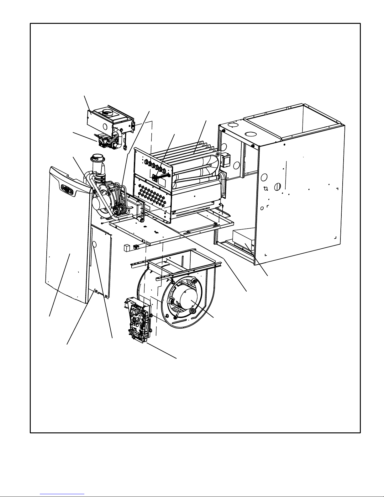
BURNER BOX ASSEMBLY
SLP98UHV PARTS ARRANGEMENT
PRESSURE SWITCHES
VARIABLE
CAPACITY
GAS VALVE
VARIABLE SPEED
COMBUSTION AIR
INDUCER
HEAT EXCHANGER
PRIMARY LIMIT
BAG ASSEMBLIES
(shipping location)
COLD END HEADER
BOX
ACCESS PANEL
SIGHT GLASS
INNER BLOWER
ACCESS PANEL
VARIABLE SPEED BLOWER MOTOR
CONTROL BOX
(includes variable capacity integrated control
transformer circuit breaker and door switch)
FIGURE 1
Page 13
Page 14
I−UNIT COMPONENTS
SLP98UHV unit components are shown in figure 1. The gas
valve, combustion air inducer and burners can be accessed
by removing the access panel. Electrical components are in
the control box (figure 2) found in the blower compartment.
SLP98UHV units are factory−equipped with a bottom return air
panel in place. The panel is designed to be field removed as
required for bottom air return. Markings are provided for side
return air and may be cut out in the field.
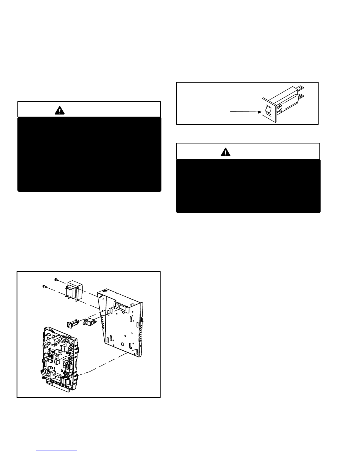
ELECTROSTATIC DISCHARGE (ESD)
Precautions and Procedures
3. Circuit Breaker (CB8)
A 24V circuit breaker is also located in the control box.
The switch provides overcurrent protection to the trans-
former (T1). The breaker is rated 3A at 32V. If the current
exceeds this limit the breaker will trip and all unit opera-
tion will shut down. The breaker can be manually reset by
pressing the button on the face. See figure 3.
CIRCUIT BREAKER CB8
CAUTION
Electrostatic discharge can affect electronic components. Take precautions during furnace installation and service to protect the furnace’s electronic controls. Precautions will help to avoid control exposure to electrostatic discharge by putting
the furnace, the control and the technician at the
same electrostatic potential. Neutralize electrostatic charge by touching hand and all tools on an
unpainted unit surface, such as the gas valve or
blower deck, before performing any service procedure.
A−Control Box 1
1. Control Transformer (T1)
A transformer located in the control box provides power to
the low voltage section of the unit. Transformers on all models are rated 40VA with a 120V primary and a 24V secondary.
2. Interlock Switch (S51)
An interlock switch rated 14A at 125VAC is wired in series
with line voltage. When the inner blower access panel is removed the unit will shut down.
CONTROL BOX SLP98UHV
TRANSFORMER
CIRCUIT
BREAKER
INTERLOCK
SWITCH
SURELIGHT®
INTEGRATED
CONTROL
FIGURE 2
PRESS TO RESET
FIGURE 3
WARNING
Shock hazard.
Disconnect power before servicing.
Integrated control is not field repairable. If control
is inoperable, simply replace entire control.
Can cause injury or death. Unsafe operation will result if repair is attempted.
4. Integrated Control (A92)
SLP98UHV units are equipped with the Lennox SureLight
variable−capacity integrated control. This control can be
used with the icomfort Touch thermostat as part of a com-
municating comfort system. The control can also operate
with a conventional single or two−stage thermostat. The
system consists of an ignition / blower control (figures 4 and
5) with control pin designations in tables 1 and 2, and ignitor.
The control provides gas ignition, safety checks and indoor
blower control with variable capacity rate gas heating. The
furnace combustion air inducer, gas valve and indoor blow-
er are controlled in response to various system inputs such
as thermostat signal, pressure and limit switch signal and
flame signal. The control features a seven−segment LED
display, indicating furnace status (including indoor blower)
and error codes. The LED flashes in single digits. For exam-
ple using table 14 under LIMIT CODE, an E" followed by 2"
followed by 5" followed by 0", the limit switch circuit is
open. The control also has two 120 volt accessory terminals
(used for a humidifier and electronic air cleaner) rated at (1)
one amp each.
®
Page 14
Page 15
Electronic Ignition
At the beginning of the heat cycle the SureLight® integrated
control monitors the low fire combustion air inducer pressure switch. The control will not begin the heating cycle if the
low fire pressure switch is closed (by−passed). Likewise the
control will not begin the high fire heating cycle if the high fire
pressure switch is closed, and will remain in low fire heat.
However, if the high fire pressure switch closes during the
low fire heat pre−purge, the control will allow high fire heat.
Once the low fire pressure switch is determined to be open,
the combustion air inducer is energized on ignition speed.
When the differential in the pressure switch is great enough,
the pressure switch closes and a 15−second pre−purge begins. If the switch is not proven within 2−1/2 minutes, the inducer is de−energized and the control will initiate vent calibration. If the vent calibration is unsuccessful the control
goes into a 5 minute delay. The control will attempt vent calibration 3 more times before going into a 1 hour soft lockout.
After the 15 second pre−purge period the SureLight ignitor
warms up for 20 seconds. The gas valve then opens for a
4−second trial for ignition. The ignitor stays energized during
this trial until flame is sensed. If ignition is not proven during
the 4−second trial for ignition, the control will try four more
times with an inter purge and warm−up time between trials of
35 seconds. After a total of five trials for ignition (including
the initial trial), the control goes into Watchguard−Flame
Failure mode. After a 60−minute reset period, the control will
begin the ignition sequence again.
Thermostat Selection Modes
See table 3 for DIP switch settings
The control can be made to operate in three modes: variable capacity, three−stage timed or two−stage. The variable
capacity and two−stage modes are only operational with a
two−stage thermostat. The thermostat selection is made using dip switches one and / or two (figure 4) and must be
positioned for the particular application.
Three−Stage Timed Operation
Using a single−stage thermostat the system will operate in a
three stage timed mode. Upon a call for heat and a successful ignition, the combustion air inducer will operate at 35%
and the indoor blower will adjust to the appropriate cfm. After a field selectable 7 or 12 minute delay period, the inducer RPM will increase and the unit will operate at 70%. The
indoor blower will adjust to the appropriate cfm. After a factory set non−adjustable 10 minute delay expires the furnace
will increase rate to 100%. The indoor blower will adjust to
the appropriate cfm.
Two−Stage Operation
The system will also operate in conventional two−stage
mode. While in two−stage mode, the furnace will fire on low
fire (70% rate). The combustion air inducer will operate at
70% and the indoor blower will adjust to the appropriate
cfm. The unit will switch to high fire on a W2 call from the
thermostat. After a 30 second recognition period (during
which the integrated control will receive a continuous W2
call) expires the furnace will increase to 100% rate. The inducer will increase to 100% speed and the indoor blower will
adjust to appropriate cfm. If there is a simultaneous call for
first and second stage heat, the unit will fire on first stage
heat and switch to second stage heat after 30 seconds of
operation.
TABLE 1
SureLight
®
Control 6 Pin Terminal Designation
PIN # Function
1 Data Input From Motor
2 Common
3 Not Used
4 Data Output To Motor
5 5 Volt Bias Supply
6 Not Used
Variable Capacity
Using a two−stage thermostat the system will operate in a
variable capacity sequence mode. In this mode, the control
will vary the firing rate anywhere between 35% and 100% of
full capacity. The indoor blower will be automatically adjusted accordingly to provide the appropriate airflow at any
rate. On the initial call for low fire, the furnace will operate at
35% and will remain there until the heat call is satisfied or a
call for high fire is initiated. If there is a call for high fire the
rate will increase by 10% if the current rate is above 60%.
However, if the current rate is below 60% the rate will increase to 70%. After this initial rate increase to 70% capacity, the furnace will increase rate by 10% every 5 minutes
while a high fire heat call is present. If the high fire heat call is
satisfied but the low fire heat call is still present, the furnace
will remain at the current firing rate until the demand is satisfied or another call for high fire is initiated.
TABLE 2
SureLight Control 12 Pin Terminal Designation
PIN # Function
1 Not used
2 High Fire Pressure Switch
3 Rollout In
4 Ground
5 24V Hot
6 Primary Limit In
7 Gas Valve
8 Gas Valve Common
9 24V Neutral
10 Ground
11 Primary Limit Switch Out
12 Low Fire Pressure Switch
Page 15
Page 16
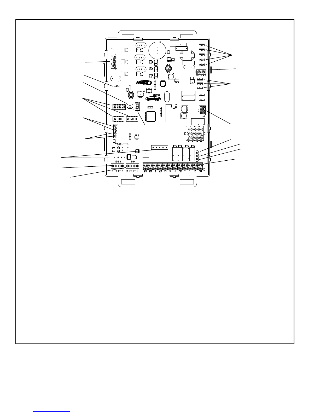
COMBUSTION
AIR INDUCER
CONNECTOR
FLAME
SENSE
DIAGNOSTIC
PUSH BUTTON
DIP SWITCHES
NEUTRAL
TERMINALS
IGNITOR
CONNECTOR
LINE VOLTAGE
+
HUM
EAC
TERMINALS
ON−BOARD
LINKS
OUTDOOR AIR
SENSOR
TERMINALS
DISCHARGE AIR
SENSOR
FACTORY TEST
HEADER PINS.
FACTORY USE ONLY.
TB83 OUTDOOR
TERMINALS
TB84 INDOOR
RS−BUS LINK (TB82, future use)
I+ = DATA HIGH CONNECTION
I − = DATA LOW CONNECTION
RS−BUS OUTDOOR (TB83)
R = 24VAC
I + = DATA HIGH CONNECTION
I − = DATA LOW CONNECTION
C = 24VAXC COMMON
RS−BUS INDOOR (TB84)
R = 24VAC
I + = DATA HIGH CONNECTION
I − = DATA LOW CONNECTION
C = 24VAXC COMMON
7−SEGMENT
DIAGNOSTIC LED
INDOOR
BLOWER
CONNECTOR
W915 Y1 TO Y2
W951 R TO O
W915
W951
W914
W914 R TO DS
L − use only with
communicating T’stat and
non−communicating outdoor
unit.
THERMOSTAT CONNECTIONS (TB1)
DS = DEHUMIDIFICATION SIGNAL
W2 = HEAT DEMAND FROM 2ND STAGE T/STAT
W1 = HEAT DEMAND FROM 1ST STAGE T/STAT
R = CLASS 2 VOLTAGE TO THERMOSTAT
G = MANUAL FAN FROM T’STAT
C = THERMOSTAT SIGNAL GROUND CONNECTED
TO TRANSFORMER GRD (TR) & CHASIS GROUND
Y1 = THERMOSTAT 1ST STAGE COOL SIGNAL
(GRD)
1/4" QUICK CONNECT TERMINALS
HUM = 120 VAC OUTPUT TO HUMIDIFIER
XMFR = 120 VAC OUTPUT TO TRANSFORMER
LI = 120 VAC INPUT TO CONTROL
CIRC = 120 VAC OUTPUT TO CIRCULATING BLOWER
EAC = 120 VAC OUTPUT TO ELECTRICAL AIR CLEANER
NEUTRALS = 120 VAC NEUTRAL
FIGURE 4
Page 16
Y2 = THERMOSTAT 2ND STAGE COOL SIGNAL
O = THERMOSTAT SIGNAL TO HEAT PUMP
REVERSING VALVE
H = 24V HUMIDIFIER OUTPUT. DO NOT CONNECT
TO COMFORTSENSE
®
THERMOSTAT
L = USE ONLY WITH A COMMUNICATING
THERMOSTAT AND A NON−COMMU-
NICATING OUTDOOR UNIT
DH = DEHUMIDIFICATION OUTPUT
COMMUNICATING THERMOSTAT
ONLY
Page 17
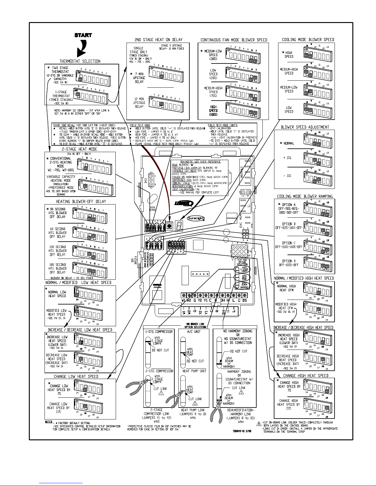
SLP98UHV INTEGRATED CONTROL CONFIGURATION GUIDE
FIGURE 5
Page 17
Page 18
Thermostat Selection Switch Settings
TABLE 3
Operation Thermostat Switch 1 Switch 2 Switch 3
Variable Capacity Heat
Two−Stage Off On Off
(35% to 100%)
Three−Stage Heat
(35%, 70%, 100%)
Single−Stage On Off 2nd stage delay
OFF = 7 minutes
ON = 12 minutes
3rd stage delay
10 minutes fixed
Two−Stage Heat (W1 70%, W2 100%) Two−Stage Off Off Off
NOTE − When the SLP98UHV is used with an icomfort
Toucht communicating thermostat, all indoor blower
speed selections and DIP switch settings are made by
the communicating thermostat.
Heating Operation DIP Switch Settings −− Figure 4
Switch 1 −− Thermostat Selection −− This unit may be used
with either a single−stage or two−stage thermostat. The thermostat selection is made using a DIP switch which must be
properly positioned for the particular application. The DIP
switch is factory−positioned for use with a two−stage thermostat. If a single−stage thermostat is to be used, the DIP
switch must be repositioned. See table 3.
NOTE − All DIP switches are factory shipped in the
OFF" position.
Switch 2 −− Operating Mode with Two−Stage Thermostat
−− If a two−stage thermostat is used, the furnace can operate
in either variable−capacity or conventional two−stage mode.
When variable−capacity mode is selected, the firing rate of
the unit is varied to maximize comfort. Conventional two−
stage mode is the factory default setting. See table 3.
Switch 3 −− Second−Stage Heat On Delay −− If a single−
stage thermostat is used, the integrated control can be used
to energize second−stage heat after either 7 minutes or 12
minutes of first−stage heat operation. See table 3.
Switches 4 and 5 −− Blower−Off Delay −− The blower−on
delay of 45 seconds is not adjustable. The blower−off delay
(time that the blower operates after the heating demand has
been satisfied) can be adjusted by moving switches 4 and 5
on the integrated control. The unit is shipped from the factory with a blower−off delay of 90 seconds. The blower off
delay affects comfort and is adjustable to satisfy individual
applications. Adjust the blower off delay to achieve a supply
air temperature between 90° and 110°F at the exact moment that the blower is de−energized. Longer off delay settings provide lower supply air temperatures; shorter settings provide higher supply air temperatures. Table 4 provides the blower off timings that will result from different
switch settings.
Blower Off Delay Switch Settings
TABLE 4
Blower Off Delay
(Seconds)
Switch 4 Switch 5
60 Off On
90 (factory) Off Off
120 On Off
180 On On
Indoor Blower Operation DIP Switch Settings
Switches 6 and 7 −− Continuous Indoor Fan Operation −−
Blower Speed − Switches 6 and 7 are used to select blower
motor speeds during continuous indoor blower operation.
The unit is shipped from the factory with DIP switches positioned for medium low (2) speed during continuous indoor
blower operation. The table below provides the continuous
blower speeds that will result from various switch settings.
Refer to blower tables at the front of this manual for corresponding cfm values.
TABLE 5
Continuous Indoor Fan
Speed Switch 6 Switch 7
1 − Low (28%) Off On
2 − Medium Low
(38%)
Off Off
(Factory)
3 − Medium High
(70%)
On Off
4 − High (100%) On On
Switches 8 and 9 −− Cooling Mode Blower Speed −−
Switches 8 and 9 are used to select cooling blower motor
speed. The unit is shipped from the factory with the DIP
switches positioned for high speed (4) indoor blower motor
operation during the cooling mode. The table below provides the cooling mode blower speeds that will result from
different switch settings. Refer to blower tables at the front
of this manual for corresponding cfm values.
TABLE 6
Cooling Mode Blower Speeds
Speed Switch 8 Switch 9
1 − Low On On
2 − Medium Low Off On
3 − Medium High On Off
4 − High (Factory) Off Off
Page 18
Page 19
Switches 10 and 11 −− Cooling Mode Blower Speed Adjustment −− Switches 10 and 11 are used to select blower
speed adjustment settings. The unit is shipped from the factory with the DIP switches positioned for NORMAL (no) adjustment. The DIP switches may be positioned to adjust the
blower speed by +10% or −10% to better suit the application.
The table below provides blower speed adjustments that
will result from different switch settings. Refer to blower
tables at the front of this manual for corresponding cfm values. With switches 10 and 11 set to ON, motor will bypass
ramping profiles and all delays and immediately upon a call
for cool, run at COOLING speed selected. LED will continue
to operate as normal. This mode is used to check motor operation.
TABLE 7
Blower Speed Adjustment
Adjustment Switch 10 Switch 11
+10% (approx.) On Off
NORMAL (Factory) Off Off
−10% (approx.) Off On
MOTOR TEST On On
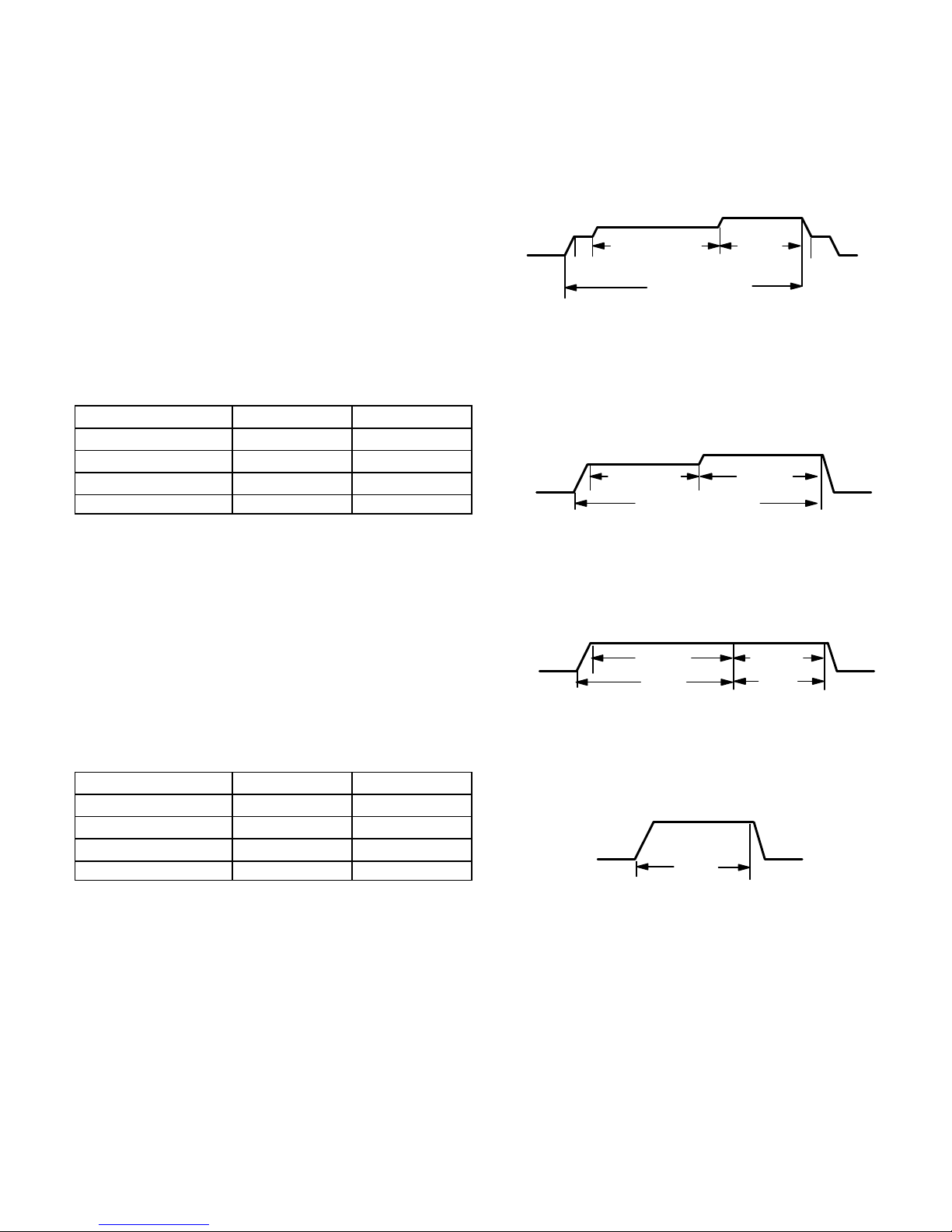
Ramping Option A (Factory Selection)
Motor runs at 50% for 30 seconds.
Motor then runs at 82% for approximately 7−1/2 min-
utes.
If demand has not been satisfied after 7−1/2 minutes,
motor runs at 100% until demand is satisfied.
Once demand is met, motor runs at 50% for 30 sec-
onds then ramps down to stop.
OFF
1/2 MIN
50% CFM
7 1/2 MIN
82% CFM
COOLING DEMAND
100%
CFM
1/2 MIN
50% CFM
OFF
Ramping Option B
Motor runs at 82% for approximately 7−1/2 minutes. If
demand has not been satisfied after 7−1/2 minutes, motor runs at 100% until demand is satisfied.
Once demand is met, motor ramps down to stop.
OFF
7 1/2 MIN
82%CFM
COOLING DEMAND
100% CFM
OFF
Switches 12 and 13 −− Cooling Mode Blower Speed
Ramping −− Switches 12 and 13 are used to select cooling
mode blower speed ramping options. Blower speed ramping may be used to enhance dehumidification performance.
The switches are factory set at option A which has the greatest effect on blower motor performance. Table 8 provides
the cooling mode blower speed ramping options that will result from different switch settings. The cooling mode blower
speed ramping options are detailed below.
TABLE 8
Cooling Mode Blower Speed Ramping
Ramping Option Switch 12 Switch 13
A (Factory) Off Off
B On Off
C Off On
D On On
Ramping Option C
Motor runs at 100% until demand is satisfied.
Once demand is met, motor runs at 100% for 45 sec-
onds then ramps down to stop.
OFF
100% CFM
DEMAND
100% CFM
45 SEC.
OFF
Ramping Option D
Motor runs at 100% until demand is satisfied.
Once demand is met, motor ramps down to stop.
100% CFM
COOLING
DEMAND
OFFOFF
Page 19
Page 20
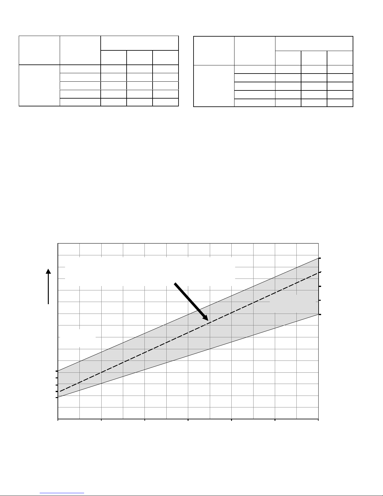
Low Heat Blower Speeds
TABLE 9
Thermostat
Demand
Blower
Speed
Adjust-
ments
DIP SWITCH SETTINGS
14 15 16
+15% On Off On
Low Heat
(R to W1)
+7.5% On Off Off
Normal Off Off Off
−7.5% On On Off
−15% On On On
Switches 14 through19 −− Heating Mode Blower Speed −−
Switches 14 through 19 are used to select heating mode
blower motor speeds. These switches are factory set at the
OFF position which provides 100 % of normal speed during
HIGH HEAT demand, 70% of normal speed during MID−
RANGE HEAT demand and 40% of normal speed during
LOW HEAT demand. Switches 14, 15 and 16 are used to
adjust the LOW FIRE blower motor speed. Switches 17, 18
and 19 are used to adjust the HIGH FIRE blower motor
speed. Figure 6 and tables 9 and 10 provides the heating
mode blower speeds that will result from different switch
settings. Figure 6 indicates the effect the DIP switch settings (tables 20 &21 above) have upon the heating airflow at
various furnace firing rates.
Refer to blower tables at the front of this manual for corresponding cfm values.
Thermostat
Demand
High Heat
(R to
W1 & W2)
High Heat Blower Speeds
TABLE 10
Blower
Speed
Adjust-
ments
DIP SWITCH SETTINGS
17 18 19
+15% On Off On
+7.5% On Off Off
Normal
Off Off Off
−7.5% On On Off
−15% On On On
Increasing
Airflow
+15%
+7.5%
Nominal
−7.5%
−15%
Airflow Determination
Identify blower speed adjustment points at low and high fire
Airflow will lie on straight line between these two points and will fall within
the shaded area as shown
EXAMPLE −7.5% at low fire +7.5% at high fire
Low Fire
Dip Switches
14, 15, 16
35%
50%
60%
70%
RATE (%)
FIGURE 6
80%
90%
High Fire
Dip Switches
17, 18, 19
+15%
+7.5%
Nominal
−7.5%
−15%
100%
Page 20
Page 21

On−Board Link W914 DS to R (Figure 4)
On−board link W914, is a clippable connection between terminals DS and R on the integrated control. W914 must be
cut when the furnace is installed with either the Harmony
III zone control or a thermostat which features humidity
control. If the link is left intact the PWM signal from the Harmony III control will be blocked and also lead to control damage. Refer to table 15 for operation sequence in applications including SLP98UHV, a thermostat which features humidity control and a single−speed outdoor unit. Table 16
gives the operation sequence in applications with a two−
speed outdoor unit.
On−Board Link W951 R to O (Figure 4)
On−board link W951 is a clippable connection between terminals R and O on the integrated control. W951 must be cut
when the furnace is installed in applications which include a
heat pump unit and a thermostat which features dual fuel
use. If the link is left intact, terminal O" will remain energized eliminating the HEAT MODE in the heat pump.
On−Board Link W915 Y1 to Y2 (Figure 4)
On−board link W915 is a clippable connection between terminals Y1 and Y2 on the integrated control. W915 must be
cut if two−stage cooling will be used. If the link is not cut the
outdoor unit will operate in second−stage cooling only.
Diagnostic LED (Figure 4)
The seven−segment diagnostic LED displays operating status, target airflow, error codes and other information. Table
14 lists diagnostic LED codes.
Diagnostic Push Button (Figure 4)
The diagnostic push button is located adjacent to the seven−
segment diagnostic LED. This button is used to enable the
Error Code Recall mode and the Field Test mode. Press the
button and hold it to cycle through a menu of options. Every
five seconds a new menu item will be displayed. When the
button is released, the displayed item will be selected. Once
all items in the menu have been displayed, the menu resumes from the beginning until the button is released.
Error Code Recall Mode
Select "E" from the menu to access the most recent 10 error
codes. Select c" from the Error Code Recall menu to clear
all error codes. Button must be pressed a second time while
c" is flashing to confirm command to delete codes. Press
the button until a solid ≡" is displayed to exit the Error Code
Recall mode.
Field Test Mode
Use the diagnostic push button to scroll through the menu
as described above. Release the button when the LED
flashes −" to select the Field Test mode.
While in the Field Test mode the technician can:
Initiate furnace ignition and move to and hold low−fire
rate by applying a R to W1 jumper.
Initiate furnace ignition sequence and move to and hold
high−fire rate by applying a jumper from R to W1 and
W2.
Initiate furnace ignition sequence and move to and hold
mid−fire rate by applying a jumper to R and W2.
Apply then remove the jumper from R to W1 and W2 to
change the firing rate from low fire to mid fire and high
fire.
A vent calibration sequence can be initiated even if a
thermostat signal is not present. Press and hold the
push button until a solid C" is displayed. Release the
button and calibration will begin. The furnace will perform the high−fire and low−fire pressure switch calibrations and display CAL". After calibration, the LED will
return to the flashing −" display.
During Field Test mode operation, all safety switches are
still in the circuit (they are not by−passed) and indoor blower
performance and timings will match DIP switch selections.
Current furnace firing rate, indoor blower CFM and flame
signal will be displayed. To exit the Field Test mode, press
and hold the button. The menu will resume from the beginning. Also, cycle the main power to exit the Field Test mode.
The integrated control will automatically exit the Field Test
mode after 45 minutes of operation.
Page 21
Page 22

TABLE 11
Idle Menu Options
These options are displayed on the menu when the button is pressed during normal operation
DISPLAY ACTION (when button released)
No change (idle) remain in idle mode
Solid E" enter diagnostic mode
Solid −" enter field test mode
NOTE − No change implies the display will continue to show whatever is currently being displayed for normal operation
Field Test Menu Options
TABLE 12
These options are displayed when the button is used in Field Test Mode
DISPLAY ACTION (when button released)
No change (blinking −") remain in field test mode
Solid −" exit field test mode
Solid c" start pressure switch calibration
TABLE 13
Field Test Menu Options
These options are displayed when the button is used in diagnostic recall mode
DISPLAY ACTION (when button released)
No change (displaying error history) remain in diagnostic recall mode
Solid (3 horizontal bars) exit diagnostic recall mode
Solid c" clear error history
Once the button is released to clear the error history a blinking c" will be shown on the display for up to 10 seconds. During this
time the user must press and release the button one additional time to confirm the action of deleting the error history. Once the
error history is deleted it cannot be recovered.
Page 22
Page 23

Configuring Unit Size Codes
Power−Up − Number displayed represents by integrated control unit size code (furnace model
and capacity). If three horizontal bars are displayed followed by continuous E203, furnace
control does not recognize unit size code. Configure per the following:
Yes
To enter Field Test
Mode: push and hold
button next to
7−segment LED display
until solid dash symbol
appears. Release
button.
If alarm is present, furnace
control will display error
code. If alarm is not
present solid dash starts
blinking on 7−segment
LED display.
Push and hold button until the solid P
symbol is displayed on the 7−segment
LED. Release button. This mode allows
the user to select a unit size code number
that matches the furnace model size and
capacity.
IMPORTANT: Field replacement controls may
need to be manually configured to validate
furnace unit size code.
Solid P starts
blinking on
7−Segment LED
Push and hold button. Integrated control will
display unit size code number for each
furnace model for five seconds.
_
P
Furnace control in IDLE mode
No heating, cooling or indoor fan
operation)
_
P
−
−
−
No
Turn room thermostat to OFF
UNIT SIZE
CODE
FURNACE MODEL
A
SLP98UHV−070−36B
b
SLP98UHV−090−36C
c
SLP98UHV−090−48C
d
SLP98UHV−090−60C
E
SLP98UHV−110−60C
F
SLP98UHV−135−60D
When the correct unit size code is displayed, release
button. Selected code will flash for 10−second period.
During that period, hold push button until code stops
blinking (disappear for 2 seconds). Integrated control
will store code in memory and will automatically exit
Field Test Mode and reset. (If second period expires
or push button is held less than five seconds, control
will automatically exit Field Test Mode and go into
IDLE mode without storing unit size code. If this
happens, programming function must be repeated).
−
Verify that the selected unit size code is correct
and stored in non−volatile memory by cycling
the 24 volt power to the furnace control. (At 24
volt power−up of the furnace control, the
7−segment LED will display a unit size code. If
three horizontal bars display, board does not
recognize unit size code. Programming
function must be repeated)
−
−
FINISHED
Page 23
Page 24

TABLE 14
LED 7 Segment Status / Error Code
Integrated Control Diagnostic Codes
Press the diagnostic push button and hold it to cycle through a menu of options. Every five seconds a new menu item will be displayed.
Release the button when the desired mode is displayed.
When a solid "P" is displayed, the furnace capacity/ size is programmed.
When the solid E" is displayed, the control enters the Error Code Recall mode. Error Code Recall mode menu options: No change (displaying error history) remains in Error Code Recall mode; solid b" exits Error Code Recall mode; and solid c" clears the error history. Must press
button while flashing c" is displayed to clear error codes.
When the solid −" is displayed, the control enters the Field Test mode. Field Test mode menu options: Solid C" starts pressure switch
calibration; blinking −" exits Field Test mode.
Code Diagnostic Codes/Status of Equipment Action Required to Clear and Recover
Idle mode (Decimal blinks at 1 Hertz −− 0.5 second ON, 0.5 second OFF).
Cubic feet per minute (cfm) setting for indoor blower (1 second ON, 0.5 second
OFF) / cfm setting for current mode displayed.
Cooling stage (1 second ON, 0.5 second OFF) / 1 or 2 displayed / Pause / cfm set-
ting displayed / Pause / Repeat codes).
Dehumidification mode (1 second ON) / 1 second OFF) / cfm setting displayed /
Pause / Repeat Codes).
Variable Capacity Heat (1 second ON, 0.5 second OFF) / % of input rate displayed /
Pause/ cfm setting / Pause/ Repeat codes.
Heat Stage (1 second ON, 0.5 second OFF) / 1 or 2 displayed / Pause / cfm setting
displayed / Pause / Repeat codes.
Defrost mode.
Device communication problem − No other devices on BUS (Communication sys-
tem).
Low line voltage. Line Voltage low (Voltage lower than nameplate rating)
High line voltage. Line Voltage High (Voltage higher than nameplate rating)
Line voltage frequency out−of−range. No 60 hertz power (Check voltage and frequency).
Low 24V − Control will restart if the error recovers. 24 voltage low (Range is 18 to 30 volts) Check voltage.
Unresponsive device. Usually caused by delay in outdoor unit responding to
Active communicating thermostat signal missing for more than 3 minutes. Equipment lost communication with the thermostat. Check
Control failed self−check, internal error, failed hardware. Will restart if error recovers.
Integrated furnace control not communicating. Covers hardware errors (flame sense
circuit faults, pin shorts, etc.).
Failed internal control communication between microcontrollers. Hardware problem on the control board. Cycle power on
Corrupted control parameters (Verify configuration of system). Reconfigure the system. Replace board if service (heating
Outdoor air sensor failure − NO error if disconnected. Only shown if shorted or out−
of−range.
Hard lockout − Rollout circuit open or previously open. Correct unit cause of rollout trip or replace flame rollout
Indoor blower communication failure − Unable to communicate with blower motor. Indoor blower communication failure including power out-
Indoor blower motor mis−match − Indoor motor horsepower does not match unit
capacity.
Appliance capacity / size is NOT programmed. Invalid unit codes refer to configura-
tion flow chart in installation instructions.
Gas valve mis−wired. Check operation of gas valve.
Gas valve control relay contact shorted. Check operation of gas valve.
Hot surface ignitor sensed open − Refer to troubleshooting in installation instruction. Measure resistance of Hot Surface Ignitor, replace if open
Equipment is unable to communicate. Check for mis wire
and loose connections and check for a high voltage source
of noise close to the system. (welder etc.).
Check voltage.
Check voltage.
indoor unit poling recycle power, check wiring.
connections and cycle power on the thermostat.
Hardware problem on the control board. Cycle power on
control. Replace if problem prevents service and is persistent.
control. Replace if problem prevents service and is persistent.
/cooling) is unavailable.
Compare outdoor sensor resistance to temperature resistance charts in installation instructions. Replace if necessary.
switch and test furnace operation.
age.
Incorrect furnace size code selected. Check unit size
codes on configuration guide or in installation instructions.
No furnace size code selected. Check unit size codes on
configuration guide or in installation instructions.
or not within specification.
Page 24
Page 25

Integrated Control Diagnostic Codes (continued)
Code Diagnostic Codes/Status of Equipment Action Required to Clear and Recover
Low pressure switch failed open − Refer to troubleshooting in installation instruc-
tion.
Low pressure switch failed closed − Refer to troubleshooting in installation instruc-
tion.
High pressure switch failed open − Refer to troubleshooting in installation instruc-
tion.
High pressure switch failed closed − Refer to troubleshooting in installation instruc-
tion.
Low pressure switch open during trial for ignition or run mode. Refer to trouble-
shooting in installation instruction.
Unable to perform successful pressure switch calibration. Retry after 300 seconds. Error counter cleared when exit-
Low flame current − Run mode − Refer to troubleshooting in installation instruction. Check micro amperes of flame sensor, clean or replace
Flame sensed out of sequence − Flame still present. Shut off gas, check for gas valve leak.
Limit switch circuit open − Refer to troubleshooting in installation instruc-
tion.
Discharge air temperature too high (gas heat only). Check temperature rise, air flow and input rate.
Soft lockout − Exceeded maximum number of retries. No flame current
sensed.
Soft lockout − Exceeded maximum number of retries. Last retry failed due
to the pressure switch opening.
Soft lockout − Exceeded maximum number of recycles. Last recycle due
to the pressure switch opening.
Soft lockout − Exceeded maximum number of recycles. Last recycle due
to flame failure.
Soft lockout − Exceeded maximum number of recycles. Last recycle
failed due to the limit circuit opening or limit remained open longer than
3 minutes.
Soft lockout − Flame sensed out of sequence from code 241 fault. Flame
signal is gone.
Soft lockout − Exceeded maximum number of calibration retries. See E 228.
Ignitor circuit fault − Failed ignitor or triggering circuitry. See E 207.
Restricted air flow − Cubic feet per minute is lower than what is needed
for minimum firing rate.
Indoor blower motor unable to start − Seized bearings, stuck wheel, etc. Indoor blower motor unable to start (seized bearing,
Combustion air inducer motor amp draw is too high. Check combustion blower bearings, wiring , am-
Check inches of water column pressure during operation
of low pressure switch on heat call, measure inches of
water column of operating pressure, inspect vent and combustion air inducer for correct operation and restriction.
Check low pressure switch for closed contacts, measure
inches of water column of operating pressure, inspect vent
and combustion air inducer for correct operation and restriction.
Check inches of water column pressure of high pressure
switch on heat call, measure inches of water column of
operating pressure, inspect vent and combustion air inducer for correct operation and restriction.
Check high pressure switch for closed contacts, measure
inches of water column of operating pressure, inspect vent
and combustion air inducer for correct operation and restriction.
Check inches of water column pressure during operation
of low pressure switch on heat call, measure inches of
water column of operating pressure, inspect vent and combustion air inducer for correct operation and restriction.
ing lockout, unable to perform pressure switch calibration.
Check vent system and pressure switch wiring connections.
sensor. Measure voltage of neutral to ground for good unit
ground.
Check why limit is tripping, overfired, low air flow.
Check for gas flow, ignitor lighting burner, flame
sensor current.
See E 223.
See E 223 and E 225.
See E 240.
See E 250.
See E 241.
Check for dirty filter, unit air flow restriction, blower
performance.
stuck wheel, etc), replace motor or wheel if assembly does not operate or meet performance.
peres, replace if it does not operate or meet performance.
Page 25
Page 26

Integrated Control Diagnostic Codes (continued)
Code Diagnostic Codes/Status of Equipment Action Required to Clear and Recover
Indoor blower motor temperature is too high. Indoor blower motor over temperature (motor
Discharge error sensor failure − No error if disconnected. Only shown if
shorted or out−of−range.
Heat rate reduced to match indoor blower air flow. Replace filter or repair
duct restriction.
Restricted air flow in cooling or continuous fan mode is lower than cfm
setting.
Indoor or outdoor unit capacity mismatch. Incorrect Indoor /outdoor capacity code selected.
Global network connection − Communication link problem. For Future Use.
No 24 Volt output on Y1 to C with non−communicating outdoor unit. Y1 relay / Stage 1 failed (Pilot relay contacts did not
No 24 Volt output on Y2 to C with non−communicating outdoor unit. Y2 relay / Stage 2 failed (Pilot relay contacts did not
No 24 Volts between R & O with non−communicating outdoor unit (Dual
fuel module required for heat pump application).
LSOM − Compressor ran more than 18 hours in air conditioning mode. Compressor protector is open. Check for high head
LSOM − Outdoor unit system pressure trip. Compressor ran over 18 hours in air conditioning
LSOM − Compressor short−cycling (Running less than 4 minutes). Outdoor unit pressure trip. Check dirty coil, fan mo-
LSOM − Compressor rotor locked. Compressor short cycling (Running less than 4 min-
LSOM − Compressor open circuit. Check capacitor, wiring, hard start kit , replace com-
LSOM − Compressor open start circuit. Check compressor for hot (cool down) , check pres-
LSOM − Compressor open run circuit.
LSOM − Compressor contactor is welded.
LSOM − Compressor low voltage. Replace contactor.
tripped on internal protector), Check motor bearings, amperes. Replace if necessary.
Discharge air temperature(DATS) out of range,
code is activated during "Field test mode".
Furnace blower in cutback mode due to restricted
airflow. Check filter and ductwork. To clear replace
filter if needed or repair/ add ductwork.
Restricted airflow − Indoor blower is running at a
reduced cubic feet per minute (Cutback Mode) −
The variable speed motor has pre−set speed and
torque limiters to protect the motor from damage
caused by operating out of its designed parameters
(0 to 0.8 inches water column total external static
pressure). Check filter and ductwork. To clear replace filter if needed or repair/ add ductwork.
Check for proper configuration in installation instructions. Alarm is just a warning. The system operation
is not impacted at all and alarm would clear when
Commissioning is exited.
close or the relay coil did not energize).
close or the relay coil did not energize).
Configuration link R to O needs to be cut on control
board.
pressure, check compressor supply voltage. Outdoor unit power disconnect is open , compressor
circuit breaker or fuse(s) is open, broken wire or
connector is not making contact. Low or high pressure switch open if present in the system. Compressor contactor has failed to close.
mode.
tor, refrigerant charge.
utes).
pressor.
sures, fan motor etc. Replace compressor if unable
to get circuit to close and compressor to operate.
Page 26
Page 27

TABLE 15
OPERATING SEQUENCE
SLP98UHV and Single−Stage Outdoor Unit
OPERATING
SEQUENCE
SYSTEM DEMAND SYSTEM RESPONSE
Demand Relative Humidity
System
Condition
Step
1st
stage
O G Status D*
NO CALL FOR DEHUMIDIFICATION
Normal Operation 1 On On On Acceptable
24
VAC
BASIC MODE (only active on a Y1 thermostat demand)
Normal Operation 1 On On On Acceptable
Dehumidification
Call
2 On On On Demand
24
VAC
0
VAC
PRECISION MODE (operates independent of a Y1 thermostat demand)
Normal Operation 1 On On On Acceptable
Dehumidification
call
Dehumidification
call ONLY
2 On On On Demand
1 On On On Demand
24
VAC
0
VAC
0
VAC
On−board links at indoor unit with a single−stage outdoor unit:
With Condensing unit − Cut W914 (R to DS) on SureLight
With Heat Pump − Cut W914 (R to DS) & W951(R to O) on SureLight
control.
*ComfortSense
®
7000 thermostat only
Compressor
High 100%
High 100%
High 70%
High 100%
High 70%
High 70%
®
control;
Blower
CFM
(COOL)
®
Comments
Compressor and indoor
blower follow thermostat
demand
Thermostat energizes Y1
and de−energizes D on a
call for de−humidification
Dehumidification mode
begins when humidity is
greater than set point
Thermostat will keep outdoor unit energized after
cooling temperature setpoint has been reached in
order to maintain room
humidity setpoint.
Page 27
Page 28

TABLE 16
OPERATING SEQUENCE
SLP98UHV and Two−Stage Outdoor Unit
OPERATING
SEQUENCE
SYSTEM DEMAND SYSTEM RESPONSE
Demand Relative Humidity
System
Condition
Step
1st
stage
2nd
stage
G
O
Status D*
NO CALL FOR DEHUMIDIFICATION
Normal Operation −
Y1
Normal Operation −
Y2
1 On On
2 On
On
On
On
On
Acceptable
Acceptable
24
VAC
24
VAC
ROOM THERMOSTAT CALLS FOR FIRST STAGE COOLING
BASIC MODE (only active on a Y1 thermostat demand)
Normal Operation 1 On On
Dehumidification
Call
2 On
On
On
On
On
Acceptable
Demand
24
VAC
0
VAC
PRECISION MODE (operates independent of a Y1 thermostat demand)
Normal Operation 1 On On
Dehumidification
call
Dehumidification
call ONLY
2 On
1 On
On
On
On
On
On
On
On
Acceptable
Demand
Demand
24
VAC
0
VAC
0
VAC
ROOM THERMOSTAT CALLS FOR FIRST AND SECOND STAGE COOLING
BASIC MODE (only active on a Y1 thermostat demand)
Normal Operation 1 On
Dehumidification
Call
2 On
On
On
On
On
On
On
Acceptable
Demand
24
VAC
0
VAC
PRECISION MODE (operates independent of a Y1 thermostat demand)
Normal Operation 1 On On
Dehumidification
call
2 On
On
On
On
On
Acceptable
Demand
24
VAC
0
VAC
Compressor
Low 70%
High 100%
Low 70%
High 70%
Low 70%
High 70%
High 70%
High 100%
High 70%
Low 70%
High 70%
Blower
CFM
(COOL)
Comments
Compressor and indoor
blower follow thermostat
demand
Thermostat energizes
2nd stage and de−energizes D on a call for de−
humidification
Dehumidification mode
begins when humidity is
greater than set point
Thermostat will keep outdoor unit energized after
cooling temperature setpoint has been reached
in order to maintain room
humidity setpoint.*
Thermostat energizes
2nd stage and de−energizes D on a call for de−
humidification
Dehumidification mode
begins when humidity is
greater than set point
Dehumidification
call ONLY
1 On
On
On−board links at indoor unit with a two−stage outdoor unit:
Cut factory link from Y1 to Y2 or cut W915 (Y1 to Y2) on SureLight
grated control.
With Condensing unit − Cut W914 (R to DS) on SureLight
With Heat Pump − Cut W914 (R to DS) & W951 (R to O) on SureLight
integrated control.
*ComfortSense
®
7000 thermostat only
On
On
Demand
Page 28
0
VAC
High 70%
®
inte-
®
integrated control;
®
Thermostat will keep outdoor unit energized after
cooling temperature setpoint has been reached
in order to maintain room
humidity setpoint.
Page 29

B−Blower Compartment (Figure 7)
Power Choke
(4 and 5 Ton Only)
To Remove Blower From Unit: Remove access panels,
Control box, Bolts and Wiring Jackplugs.
1. Blower Motor (B3)
Blower Motor
(B3)
Then Slide Out Front of Unit.
FIGURE 7
WARNING
During blower operation, the ECM motor emits energy that may interfere with pacemaker operation. Interference is reduced by both the sheet metal cabinet
and distance.
The SLP98UHV line uses three different motor sizes; 1/2 hp,
3/4 hp and 1hp. The motor communicates with the integrated
control via a 2−way serial connection. The motor receives all
necessary functional parameters from the integrated control
and does not rely on a factory program like traditional variable
speed motors. SLP98UHV units use a three-phase, electronically controlled D.C. brushless motor (controller converts
single phase a.c. to three phase D.C.), with a permanentmagnet-type rotor (figure 8). Because this motor has a permanent magnet rotor it does not need brushes like conventional
D.C. motors.
Internal components are shown in figure 8. The stator windings are split into three poles which are electrically connected to
the controller. This arrangement allows motor windings to
turn on and off in sequence by the controller.
IMPORTANT
Earlier ECM motors used on other Lennox furnace
models are not interchangeable with motors used on
the SLP98UHV furnace line.
A solid-state controller is permanently attached to the
motor. The controller is primarily an A.C. to D.C. converter. Converted D.C. power is used to drive the motor. The
controller contains a microprocessor which monitors
varying conditions inside the motor (such as motor workload).
SLP98UHV BLOWER MOTOR COMPONENTS
STATOR
(WINDINGS)
BEARING
ROTOR
FIGURE 8
The controller uses sensing devices to sense what position
the rotor is in at any given time. By sensing the position of the
rotor and then switching the motor windings on and off in sequence, the rotor shaft turns the blower.
All SLP98UHV blower motors use single phase power.
An external run capacitor is not used. The motor uses
permanently lubricated ball-type bearings.
Internal Operation
The motor is controlled via serial communication between
the integrated control on the furnace and the controller attached to the motor shell. The messages sent back and
forth between the two controls serve to communicate rotational direction, demand, motor size, current draw, torque,
and rpm, among other variables.
Motor rpm is continually adjusted internally to maintain constant
static pressure against the blower wheel. The controller monitors the static work load on the motor and motor amp-draw to
determine the amount of rpm adjustment. Blower rpm may be
adjusted any amount in order to maintain a constant cfm as
shown in Blower Ratings Tables. The cfm remains relatively
stable over a broad range of static pressure. Since the blower
constantly adjusts rpm to maintain a specified cfm, motor rpm is
not rated. Hence, the terms cool speed", heat speed " or
speed tap" in this manual, on the unit wiring diagram and on
blower B3, refer to blower cfm regardless of motor rpm.
Initial Power Up
When line voltage is applied to B3, there will be a large inrush
of power lasting less than 1/4 second. This inrush charges a
bank of DC filter capacitors inside the controller. If the disconnect switch is bounced when the disconnect is closed, the disconnect contacts may become welded. Try not to bounce the
disconnect switch when applying power to the unit.
Page 29
Page 30

Motor Start-Up
When B3 begins start-up, the motor gently vibrates back and
forth for a moment. This is normal. During this time the electronic controller is determining the exact position of the rotor.
Once the motor begins turning, the controller slowly eases the
motor up to speed (this is called soft-start"). The motor may
take as long as 10-15 seconds to reach full speed. If the motor
does not reach 200 rpm within 13 seconds, the motor shuts
down. Then the motor will immediately attempt a restart. The
shutdown feature provides protection in case of a frozen bearing or blocked blower wheel. The motor may attempt to start
eight times. If the motor does not start after the eighth try, the
controller locks out. Reset controller by momentarily turning off
power to unit.
BLOWER B3 HARNESS CONNECTORS
P48 5 Pin
SHAFT
P49 4 Pin
MOTOR with INTEGRATED
CONTROLLER
J48 5 Pin
The DC filter capacitors inside the controller are connected
electrically to the motor supply wires. The capacitors take
approximately 5 minutes to discharge when the disconnect
is opened. For this reason it is necessary to wait at least 5
minutes after turning off power to the unit before attempting to service motor.
DANGER
Disconnect power from unit and
wait at least five minutes to allow
capacitors to discharge before attempting to service motor. Failure
to wait may cause personal injury
or death.
Power Choke (L13)
A choke coil is used on SLP98UHV 4 and 5 ton units
equipped with 3/4 hp and 1 hp motors.The choke is located
on the blower housing and is used to suppress transient current
spikes.
J49 4 Pin
J49 4 Pin Control Connector
J48 5 Pin Line Voltage Connector
FIGURE 9
Page 30
Page 31

Troubleshooting
To verify motor operation see steps below:
1− Remove J48 (5 pin power plug) from P48 on the motor.
2− With the power on at the furnace and door switch depressed, use a test meter to verify 120V between pins 4
and 5 on J48.
3− Reconnect J48 to P48 on the motor.
4− Remove J49 (4 pin low voltage connector) from P49
on the motor.
5− Using test jumpers, apply 24V to pins 3 and 4 on P49
on the motor.
Note: Do not apply 24V to pins 2 and 4 on P49. Doing so
will cause permanent damage to the motor.
6− Motor should run at 75%.
7− Test is complete. Remove jumpers and reconnect
plugs.
Another option is to use the TECMate PRO motor tester
with the 16 to 4 pin adaptor. The use of the TECMate PRO
isolates the motor from the integrated control. Follow the
instructions provided with the kit. If the motor runs do not
replace.
BLOWER B3 HARNESS CONNECTORS
P48 5 Pin
P49 4 Pin
SHAFT
MOTOR with INTEGRATED
CONTROLLER
P48 5 Pin
P49 4 Pin
C−Heating Components
1. Ignitor (Figure 11)
The SureLight® ignitor is made of durable silicon nitride. Ignitor longevity is enhanced by controlling voltage to the ignitor. The integrated control provides 120 volts to the ignitor
for a consistent ignition. Due to this feature of the control,
voltage measured with a digital meter will be slightly lower.
To measure correct voltage use a true RMS meter or ignitor
can be ohmed. Ohm value should be 39 to 70.
2. Flame Sensor (Figure 11)
A flame sensor (figure 11) is located on the left side of the
burner support. The sensor is mounted on the flame rollout
plate and the tip protrudes into the flame envelope of the
left−most burner. The sensor can be removed for service
without removing any part of the burners. During operation,
flame is sensed by current passed through the flame and
sensing electrode. The SureLight control allows the gas
valve to remain open as long as flame signal is sensed. To
check flame sense signal use the push−button found on the
integrated control and go to Field Test Mode. The menu will
display the flame signal. Table 17 shows the flame signal for
the SLP98UHV unit.
TABLE 17
Flame Signal in Microamps
J48 Connector
installed on motor
P49 4 Pin
1
2
3
4
5
120v
0
J48 Connector
240v
Normal Low Drop Out
2.6 or greater 2.5 or less 1.1
NOTE − A much higher than normal micro amp reading (15
for example) may appear when checking flame signal.
Page 31
24v Transformer
J49 Connector
FIGURE 10
Page 32

3. Flame Rollout Switches (Figure 11)
Flame rollout switch S47 is a high temperature limit located
inside the burner box. Each furnace is equipped with two
identical switches. The limit is a N.C. SPST manual-reset
limit connected in series with the primary limit S10. When
S47 senses rollout, the circuit breaks and the integrated
control immediately stops ignition and closes the gas valve.
If unit is running and flame rollout is detected, the gas valve
will close and integrated control will be disabled. Rollout
can be caused by a blocked heat exchanger, flue or lack of
combustion air. The switch is factory set to trip (open) at
210°F and cannot be adjusted. The switch can be manually
reset. To manually reset a tripped switch, push the reset button located on the center of the switch.
4. Burners (Figure 11)
All units use inshot burners. Burners are factory set and require no adjustment. Always operate the unit with the burner
box front panel in place. Each burner uses an orifice (see table
29 for orifice size) that is precisely matched to the burner input.
Burner Box Assembly
Burners can be removed as a one piece assembly for service.
If burner assembly has been removed, it is critical to align cen-
ter of each burner to the center of the clamshell when re−instal-
ling. See more detail in Section VII− MAINTENANCE..
5. Duralock Plus Heat Exchanger (Figure 12)
SLP98UHV units use an aluminized steel primary and
stainless steel secondary heat exchanger assembly.
Heat is transferred to the air stream from all surfaces of
the heat exchanger. The shape of the heat exchanger en-
sures maximum efficiency.
The combustion air inducer pulls fresh air through the burn-
er box. This air is mixed with gas in the burners. The gas / air
mixture is then burned at the entrance of each clamshell.
Combustion gases are then pulled through the primary and
secondary heat exchangers and exhausted out the exhaust
vent pipe.
rollout switch
flame sensor
burner assembly
intake air collar
ignitor
burner box front cover
(remove screw to open cover)
sight glass
FIGURE 11
Page 32
Page 33

6. Primary Limit Control (S10)
Figure 12 shows the primary limit (S10) used on SLP98UHV
units located in the heating vestibule panel. When excess heat
is sensed in the heat exchanger, the limit will open. Once the
limit opens, the furnace control energizes the supply air
blower and de−energizes the gas valve. The limit automatically resets when unit temperature returns to normal. The
switch is factory set and cannot be adjusted. In the event of
restricted air flow, the integrated control will reduce firing
rate and indoor blower airflow in 10% increments until a sustainable air flow is reached. If the furnace reaches 35% firing rate, and adequate air flow is not available, the furnace
will shutdown and enter one hour watchguard. For limit replacement remove wires from limit terminals and rotate limit
switch 90 degrees. Slowly remove from the vestibule panel.
A 24VAC 2−pin plug and gas control switch are located on the
valve. 24V applied to the pins enables valve operation.
Inlet and outlet pressure taps are located on the valve.
LPG change over kits are available from Lennox. Kits include
burner orifices and an LP gas valve.
DANGER
Danger of explosion.
There are circumstances in which odorant used with
LP/propane gas can lose its scent. In case of a leak,
LP/propane gas will settle close to the floor and may
be difficult to smell. An LP/propane leak detector
should be installed in all LP applications.
Primary Limit Location and Heat Exchanger
install limit face down
FIGURE 12
7. Gas Valve (GV1)
The SLP98UHV uses a variable capacity gas valve (figure
44) and is applicable for two−stage or variable capacity settings. See Thermostat selection modes" in the integrated
control section (section A− subsection 4.) for more details
The valve is internally redundant to assure safety shut−off. If
the gas valve must be replaced, the same type valve must
be used.
The burner box is sealed and operates under a negative
pressure. A pressure hose is connected from the burner box
to the gas valve. The gas valve senses the pressure in the
burner box and uses that to set the maximum manifold pres-
sure while the pressure switch with pressure conditioning
device adjusts the gas flow. This will compensate for differ-
ent vent configurations which can greatly affect the rate of
the unit.
NEGATIVE AIR
PRESSURE PORT
INLET
SUPPLY
PRESSURE
TAP
GAS VALVE SHOWN IN THE ON POSITION
POSITIVE AIR
PRESSURE PORT
OUTLET
MANIFOLD
PRESSURE TAP
FIGURE 13
Page 33
Page 34

8. Combustion Air Inducer (B6) & Pressure Switch
(S18)
All SLP98UHV units are equipped with a combustion air inducer (B6) and dual pressure switch assembly (high fire and
low fire). The pressure switch (figure 14) serves four functions. First it establishes calibration points for the vent calibration routine. The combustion air inducer’s speed at a given firing rate is a function of the vent system resistance. The
calibration routine establishes the inducer speed required to
make low and high fire switches for a given vent pipe installation and interpolates the speeds required to achieve all intermediate rates between these two points. The setting for low−
fire switch on the assembly is such that it does not normally
enter into the vent calibration routine.
Second, the switch proves combustion air inducer operation
by sensing a vacuum energizing the control circuit and allowing ignition. The low fire pressure switch provides this function.
Third, the switch interrupts the combustion process in the
event vent outlet or combustion air intake blockage.
Finally, the switch interrupts the combustion process if the
condensate drainage system becomes blocked to the point
the condensate level builds up in the cold end header box/
secondary coil or vent system.
WARNING
The pressure switch is a safety shut−down control
in the furnace and must not be jumpered for any
reason other than troubleshooting.
To troubleshoot the pressure switch, add a temporary jumper.
The unit will not fire with the switch jumpered. Therefore, the
pressure switch must be bypassed after the combustion air inducer is activated. This will determine if the pressure switch
and furnace are operating properly. However, this may not indicate if the sealed combustion system is operating properly.
Pressure Switch (S18)
low fire
bracket
high fire
If the switch assembly is to be replaced, replace the entire
assembly. Individual switch components cannot be replaced.
FIGURE 14
Page 34
Page 35

Vent Calibration
The vent calibration sequence establishes furnace operating parameters in a specific installation. The integrated control runs the calibration and may be repeated as necessary
to maintain proper furnace operation. Prior to calibration, all
duct work (and returns) vent pipe and condensate trap
(primed) must be connected.
If calibration is successful the data is stored in memory and
will be used to determine furnace operation and maintain
parameters during heat call. If calibration is not successful,
the integrated control will proceed to a 5 minute delay and
signal the appropriate code. After the 5 minute delay the calibration will be repeated 4 more times with a 5 minute delay
in between. If still unsuccessful after the 4 trials (total 5) the
integrated control will go into a 1 hour soft lockout.
Calibration may be initiated by:
Initial call for heat
Cycling main power off / on and then call for heat
Venting conditions change (affecting high and low
pressure switch operation)
Ramp down low fire switch check failed (calibration
will follow next call for heat)
The service technician (by pressing the push button
found on the integrated control until the control cycles
through to Field Test Mode")
The integrated control will do the following during
calibration:
1− Verify both low pressure switch and high pressure
switch are open. If either are closed log error and end
calibration.
2− Start inducer at a predetermined low RPM (1600).
3− After a 7.5 second delay and if the low pressure
switch is still open, increase the RPM by 250. If after a 5
second delay the low pressure switch is still open, repeat steps 1, 2 and 3.
4− Decrease RPM by 50, wait 5 seconds and look for the
low pressure switch to open. Repeat this step until it is
closed.
5− Keep this RPM as RPM1.
6− Increase RPM to 1250. Wait 5 seconds.
7− Check high pressure switch, if open, increase RPM
by 250. Repeat this step until closed.
8− Decrease RPM by 50, check after 5 seconds. Repeat
this step until switch is open.
9− Keep this RPM as RPM2.
10− Set RPM to 0. End calibration.
NOTE − If after a successful calibration and a heat call is
present the integrated control will by−pass the prepurge
state and go straight into ignitor warm up.
After calibration, the integrated control stores the RPM1
and RPM2 values. The low fire (35%) and high fire (100%)
RPM points are calculated by adding margin values to the
RPM1 and RPM2 values.
The integrated control also initiates a low fire switch check
at the end of a normal heating cycle described below. If this
check fails the pressure switch calibration will follow on the
next call for heat.
1− The inducer runs 15 seconds at the last firing rate
before the heat call ended.
2− Inducer runs at 35% firing rate RPM (RPM1 + low
pressure switch open RPM margin value).
3− If low pressure switch is open, set flag for calibration
on next call for heat. Turn inducer off until next call for
heat.
4− If low pressure switch is closed move inducer speed
to RPM1. Allow 5 seconds for stabilization.
5− If low pressure switch opens turn off inducer. No further action.
6− If low pressure switch is still closed, decrease inducer speed 1/2 of the low pressure switch open RPM margin. Allow 5 seconds to stabilize.
7− If low pressure switch is open turn off inducer. No further action.
8− If low pressure switch is still closed, set flag for calibration on next call for heat and turn off inducer.
Measuring pressure differential Figure 15
Checks of pressure differential can aid in troubleshooting. Lennox provides a kit (10L34) if necessary. When measuring the
pressure differential, readings should be taken at the pressure
switch. Lack of differential usually indicates problems in the intake or exhaust piping, but may i n di c at e pr o b l e m s i n the
heat exchanger, condensing coil, header boxes, combustion inducer or other components.
The differential pressure is the difference in pressure measured across the cold end header box orifice.
Page 35
Page 36

Measuring Pressure Differential
RED TUBING
NEGATIVE
BLACK TUBING
POSITIVE
1 − Remove thermostat demand and allow unit to cycle off.
2 − Install a tee in the negative (−) line (red tubing) and a tee in the
positive (+) line (black tubing) running from the pressure
switch to the cold end header box.
3 − Install a manometer with hose from the negative (−) side of
the manometer to the tee installed in the negative (−) line
and with hose from the positive (+) side of the manometer
to the tee in the positive (+) line.
NOTE − Both sides of the cold end header box are negative.
However the (+) port reads less negative pressure than the (−)
port.
FIGURE 15
The CAI is installed on the cold end header box. The cold
end header box is a single piece made of hard plastic. The
box has an internal channel where the combustion air inducer creates negative pressure at unit start up. The
channel contains an orifice used to regulate flow created
by the CAI. The box has pressure taps for the CAI pressure switch hoses.
The pressure switch measures the pressure differential
across the CAI orifice (difference in the channel and cold
end header box). See table 18 for orifice size per unit. If
replacement is necessary the gaskets used to seal
the box to the vestibule panel and the CAI to the box,
must also be replaced.
TABLE 18
SLP98UHV Unit C.A.I. Orifice Size
4 − Operate unit and observe manometer reading.
Readings will change as heat exchanger warms.
a. Take one reading immediately after start-up.
b. Take a second reading after unit has reached steady
state (approximately 5 minutes). This will be the pressure
differential.
The pressure differential should be greater
than those listed in table 19.
5 − Remove thermostat demand and allow to cycle off.
6 − Remove manometer and tee’s. Reinstall combustion air
sensing hoses to the pressure switch.
TABLE 19
Pressure Switch
0’ to 7500’
SLP98UHV Unit
Set Point
High Fire
Set Point
Low Fire
−070
−090
−110
1.00 + 0.05 0.25 + 0.05
−135
*Units over 7500 ft will require a conversion kit. See table 29.
−070 0.780
−090 0.920
−110 1.030
−135 1.170
Page 36
Page 37

II−icomfort Touch thermostat (if applicable)
In communicating applications the Lennox icomfort
Touch thermostat must be used. In these applications the
icomfort Touch thermostat overrides the DIP switch set-
tings on the integrated control. Refer to the illustrations provided with the thermostat for installation, set−up and operation.
See figures 16 and 17 for icomfort Touch thermostat wiring in communicating applications.
icomfort Touch Thermostat with SLP98UHV
and Non−Communicating Outdoor Unit
icomfort Touch Thermostat
icomfort−Enabled SLP98UHV Indoor Furnace
Non−Communicating Outdoor Air Conditioner
icomfort−
ENABLED
SLP98UHV
OPTIONAL
DISCHARGE
AIR SENSOR
icomfort Touch
THERMOSTAT
FURNACE
OPTIONAL
OUTDOOR
AIR SENSOR
NON−COMMUNICATING
OUTDOOR AIR
CONDITIONING UNIT −
1 OR 2 STAGE
icomfort Touch Thermostat with SLP98UHV
and icomfort−ENABLED Outdoor Unit
icomfort Touch Thermostat
icomfort−Enabled SLP98UHV Indoor Furnace
icomfort−Enabled Outdoor Air Conditioner or Heat Pump
icomfort−
ENABLED
SLP98UHV
FURNACE
OPTIONAL
DISCHARGE
AIR SENSOR
OPTIONAL
OUTDOOR
AIR SENSOR
icomfort TOUCH
THERMOSTAT
icomfort− ENABLED
OUTDOOR AIR CONDITIONING
OR HEAT PUMP UNIT
CLIP Y1 TO Y2 FOR
TWO−STAGE OPERATION
FIGURE 16
Page 37
Page 38

Optional Accessories for use with any icomfort System
Optional Accessories for use with any icomfort Touch System
DISCHARGE AIR SENSOR
icomfort Touch
THERMOSTAT
NOTE: 24V UV LIGHT
APPLICATIONS
Furnace transformer will not have adequate va to power 24v UV light applications. An additional transformer
for UV light applications is required.
icomfort−
ENABLED
SLP98UHV
FURNACE
NOTE: icomfort THERMOSTAT SENSES HUMIDITY & CONTROLS
24V H" OUTPUT (& 120V H" OUTPUT) TO CYCLE HUMIDIFIER
BASED ON DEMAND. NO OTHER CONTROL OR HUMIDISTAT
REQUIRED.
OPTIONAL OUTDOOR AIR SENSOR FOR USE WITH HUMIDIFIER (IF NOT ALREADY IN THE SYSTEM FOR OTHER
FUNCTIONS. BUILT INTO ALL icomfort OUTDOOR UNITS).
icomfort−
ENABLED
SLP98UHV
FURNACE
icomfort−
ENABLED
SLP98UHV
FURNACE
HEPA BYPASS FILTER
X2680 HEPA
INTERLOCK KIT
LVCS VENTILATION
CONTROL SYSTEM
SEE LVCS VENTILATION
INSTRUCTIONS FOR
DAMPER & SENSOR WIRING
PASS INDOOR BLOWER
MOTOR COMMON WIRE
THROUGH CURRENT LOOP.
SEE HEPA INTERLOCK KIT
FOR INSTALLATION DETAILS
FIGURE 17
icomfort−
ENABLED
SLP98UHVFURNACE
icomfort−
ENABLED
SLP98UHV
FURNACE
(C)
icomfort− ENABLED
OUTDOOR AIR
CONDITIONING OR
HEAT PUMP UNIT
NON−COMMUNICATING
1 OR 2 STAGE AC OR HP UNIT
(C)
(disables out-
door unit only)
Page 38
Page 39

III−PLACEMENT AND INSTALLATION
Pipe & Fittings Specifications
All pipe, fittings, primer and solvent cement must conform
with American National Standard Institute and the American Society for Testing and Materials (ANSI/ASTM) standards. The solvent shall be free−flowing and contain no
lumps, undissolved particles or any foreign matter that adversely affects the joint strength or chemical resistance of
the cement. The cement shall show no gelation, stratification, or separation that cannot be removed by stirring. Refer to table 20 for approved piping and fitting materials.
PIPING AND FITTINGS SPECIFICATIONS
Schedule 40 PVC (Pipe) D1785
Schedule 40 PVC (Cellular Core Pipe) F891
Schedule 40 PVC (Fittings) D2466
Schedule 40 CPVC (Pipe) F441
Schedule 40 CPVC (Fittings) F438
SDR−21 PVC or SDR−26 PVC (Pipe) D2241
SDR−21 CPVC or SDR−26 CPVC (Pipe) F442
Schedule 40 ABS Cellular Core DWV (Pipe) F628
Schedule 40 ABS (Pipe) D1527
Schedule 40 ABS (Fittings) D2468
ABS−DWV (Drain Waste & Vent)
(Pipe & Fittings)
PVC−DWV (Drain Waste & Vent)
Pipe & Fittings)
PRIMER & SOLVENT CEMENT
PVC & CPVC Primer F656
PVC Solvent Cement D2564
CPVC Solvent Cement F493
ABS Solvent Cement D2235
PVC/CPVC/ABS All Purpose Cement For
Fittings & Pipe of the same material
ABS to PVC or CPVC Transition Solvent
Cement
CANADA PIPE & FITTING & SOLVENT
CEMENT
PVC & CPVC Pipe and Fittings
PVC & CPVC Solvent Cement
ABS to PVC or CPVC Transition Cement
TABLE 20
D2661
D2665
ASTM
SPECIFICATION
D2564, D2235, F493
D3138
MARKING
ULCS636
CAUTION
Solvent cements for plastic pipe are flammable liquids and should be kept away from all sources of ignition. Do not use excessive amounts of solvent cement when making joints. Good ventilation should be
maintained to reduce fire hazard and to minimize
breathing of solvent vapors. Avoid contact of cement
with skin and eyes.
IMPORTANT
SLP98UHV exhaust and intake connections are made
of PVC. Use PVC primer and solvent cement when using PVC vent pipe. When using ABS vent pipe, use
transitional solvent cement to make connections to
the PVC fittings in the unit.
Use PVC primer and solvent cement or ABS solvent cement
meeting ASTM specifications, refer to Table 20. As an alternate, use all purpose cement, to bond ABS, PVC, or CPVC
pipe when using fittings and pipe made of the same materials. Use transition solvent cement when bonding ABS to either PVC or CPVC.
Low temperature solvent cement is recommended. Metal or
plastic strapping may be used for vent pipe hangers. Uniformly apply a liberal coat of PVC primer for PVC
Canadian Applications Only − Pipe, fittings, primer and
solvent cement used to vent (exhaust) this appliance
must be certified to ULC S636 and supplied by a single
manufacturer as part of an approved vent (exhaust) system. In addition, the first three feet of vent pipe from the
furnace flue collar must be accessible for inspection.
Table 21 lists the available exhaust termination kits.
Page 39
Page 40

SLP98UH
UNIT
OUTDOOR TERMINATION KITS USAGE
TABLE 21
STANDARD CONCENTRIC
Outdoor Ex-
VENT
PIPE
DIA.
(in.)
haust Accel-
erator
(Dia. X
Length)
1−1/2" X 12" 2" X 12"
2 YES YES YES* YES YES YES
Outdoor Exhaust Accel-
erator
(Dia. X
Length)
2" Wall Plate
Kit
22G44
or 30G28
3" Wall Plate
Kit
44J40
or 81J20
2" Wall
Ring Kit
15F74 51W11**
FlushMount
Kit
Concentric
44W92
1−1/2"
Kit
71M80
or
2" Con-
centric Kit
69M29
or
44W92
3" Con-
centric Kit
60L46
or 44W93
070
090
110
135 3 YES
*Requires field−provided and installed 1−1/2" exhaust accelerator.
** Kit 51W11 is provided with a 1−1/2" accelerator which must be used with all SLP98UH−070 and SLP98UH−090.
Termination kits 44W92, 44W93, 30G28 and 81J20 are approved for use in Canadian installations.
The 44W92 concentric kit includes a 1−1/2" accelerator which must be installed on the exhaust outlet when this kit is used with the SLP98UH070V36B furnaces.
2−1/2 YES YES YES* YES YES YES
3 YES YES YES* YES YES YES
2 YES YES YES YES YES YES
2−1/2 YES YES YES YES YES YES
3 YES YES YES YES YES YES
2−1/2 YES YES YES YES YES
3 YES YES YES YES YES
YES
YES YES
6 − Promptly apply solvent cement to end of pipe and in-
Joint Cementing Procedure
All cementing of joints should be done according to the
specifications outlined in ASTM D 2855.
side socket surface of fitting. Cement should be applied lightly but uniformly to inside of socket. Take care
to keep excess cement out of socket. Apply second
coat to end of pipe.
DANGER
DANGER OF EXPLOSION!
Fumes from PVC glue may ignite during system
check. Allow fumes to dissipate for at least 5 minutes
before placing unit into operation.
1 − Measure and cut vent pipe to desired length.
2 − Debur and chamfer end of pipe, removing any ridges or
rough edges. If end is not chamfered, edge of pipe may
remove cement from fitting socket and result in a leak-
ing joint.
3 − Clean and dry surfaces to be joined.
4 − Test fit joint and mark depth of fitting on outside of pipe.
5 − Uniformly apply a liberal coat of PVC primer for PVC or
use a clean dry cloth for ABS to clean inside socket sur-
face of fitting and male end of pipe to depth of fitting
socket.
NOTE − Time is critical at this stage. Do not allow primer to dry before applying cement.
7 − Immediately after applying last coat of cement to pipe,
and while both inside socket surface and end of pipe
are wet with cement, forcefully insert end of pipe into
socket until it bottoms out. Turn PVC pipe 1/4 turn during assembly (but not after pipe is fully inserted) to distribute cement evenly. DO NOT turn ABS or cellular
core pipe.
NOTE − Assembly should be completed within 20 seconds after last application of cement. Hammer blows
should not be used when inserting pipe.
8 − After assembly, wipe excess cement from pipe at end
of fitting socket. A properly made joint will show a bead
around its entire perimeter. Any gaps may indicate a
defective assembly due to insufficient solvent.
9 − Handle joints carefully until completely set.
Page 40
Page 41

Venting Practices
Piping Suspension Guidelines
SCHEDULE 40 PVC −−
Support every 5 feet.
All other pipe* −−
Support every 3 feet.
9. In areas where piping penetrates joists or interior walls,
hole must be large enough to allow clearance on all
sides of pipe through center of hole using a hanger.
10. When furnace is installed in a residence where unit is
shut down for an extended period of time, such as a
vacation home, make provisions for draining condensate
collection trap and lines.
Exhaust Piping (Figures 22 and 23)
* See table20 for allowable pipe.
NOTE − Isolate piping at the point where it exits the outside wall or
roof in order to prevent transmission of vibration to the structure.
Wall Thickness Guidelines
24" maximum
3/4" minimum
inside outside
Wall
FIGURE 18
REPLACING FURNACE THAT WAS PART OF A
CHIMNEY
OR GAS
VENT
(Check sizing
for water
heater only)
FURNACE
(Replaced
by SLP98)
If an SLP98UHV furnace replaces a furnace which was
commonly vented with another gas appliance, the size
of the existing vent pipe for that gas appliance must be
checked. Without the heat of the original furnace flue
products, the existing vent pipe is probably oversized for
the single water heater or other appliance. The vent
should be checked for proper draw with the remaining
appliance.
COMMON VENT SYSTEM
WATER
HEATER
OPENINGS
(To Adjacent
Room)
FIGURE 19
11. Route piping to outside of structure. Continue with
installation following instructions given in piping termination section.
CAUTION
Do not discharge exhaust into an existing stack or
stack that also serves another gas appliance. If vertical discharge through an existing unused stack is required, insert PVC pipe inside the stack until the end
is even with the top or outlet end of the metal stack.
CAUTION
The exhaust vent pipe operates under positive pressure and must be completely sealed to prevent leakage of combustion products into the living space.
Vent Piping Guidelines
The SLP98UHV is installed only as a Direct Vent gas central furnace.
NOTE − In Direct Vent installations, combustion air is taken
from outdoors and flue gases are discharged outdoors.
Intake and exhaust pipe sizing −− Size pipe according to
tables 22 and 23. Table 22 lists the minimum vent pipe
lengths permitted. Table 23 lists the maximum pipe lengths
permitted.
Regardless of the diameter of pipe used, the standard roof
and wall terminations described in section Exhaust Piping
Terminations should be used. Exhaust vent termination
pipe is sized to optimize the velocity of the exhaust gas as it
exits the termination. Refer to table 24.
In some applications which permit the use of several different sizes of vent pipe, a combination vent pipe may be used.
Contact Lennox’ Application Department for assistance in
sizing vent pipe in these applications.
Use the steps in figure 21 to correctly size vent pipe diameter.
Page 41
Page 42

Exhaust Pipe
12" Min.
12" max
of straight pipe
Horizontal Application
Horizontal Application
NOTE − All horizontal runs of exhaust pipe must slope back toward unit. A minimum of 1/4" (6mm) drop for each 12" (305mm)
of horizontal run is mandatory for drainage.
NOTE − Exhaust pipe MUST be glued to furnace exhaust fittings.
NOTE − Exhaust piping should be checked carefully to make
sure there are no sags or low spots.
FIGURE 20
NOTE − The exhaust collar on all models is sized to accommodate 2" Schedule 40 vent pipe. When vent pipe
which is larger than 2" must be used in an upflow application, a 2" elbow must be applied at the exhaust collar in order to properly transition to the larger diameter vent pipe.
This elbow must be added to the elbow count used to determine acceptable vent lengths. Contact the Application
Department for more information concerning sizing of
vent systems which include multiple pipe sizes.
1
Furnace capacity?
Which termination?
2
3
4
5
Which needs
most elbows?
How many?
Desired pipe size?
070, 090, 110
or 135 btuh
Standard or
Concentric?
See table
21
Intake or
exhaust?
2", 2 1/2", 3"
IMPORTANT
Do not use screens or perforated metal in exhaust or
intake terminations. Doing so will cause freeze−ups
and may block the terminations.
MINIMUM VENT PIPE LENGTHS
SLP98UHV
MODEL
070, 090
110**
135***
*Any approved termination may be added to the minimum equivalent length
listed.
TABLE 22
MIN. EQUIV.
VENT
LENGTH
15 ft.*
EXAMPLE
5 ft. plus 2 elbows of 2", 2−1/2",
3" or 4" diameter pipe
5 ft. plus 2 elbows of 2−1/2" 3" or
4" diameter pipe
5 ft. plus 2 elbows of 3" or 4"
diameter pipe
6
What is the altitude?
Use table 23 to
7
find max pipe
length
FIGURE 21
Page 42
Page 43

Number
Of 90°
Elbows
Used
Number
Of 90°
Elbows
Used
Maximum Allowable Vent Length in Feet
TABLE 23
Standard Termination at Elevation 0 − 7500’
Pipe
Size
Model 070 090 110 135 070 090 110 135 070 090 110 135
1 91 69
2 86 64 135 88 38 157 138 113 109
3 81 59 130 83 33 152 133 108 104
4 76 54 125 78 28 147 128 103 99
5 71 49 120 73 23 142 123 98 94
6 66 44 11 5 68 18 137 118 93 89
7 61 39 11 0 63 13 132 113 88 84
8 56 34 105 58
9 51 29 100 53 122 103 78 74
10 46 24 95 48 11 7 98 73 69
Pipe
Size
Model 070 090 110 135 070 090 110 135 070 090 110 135
1 66 44
2 61 39 11 0 63 132 113 88 84
3 56 34 105 58 127 108 83 79
4 51 29 100 53 122 103 78 74
5 46 24 95 48 11 7 98 73 69
6 41 19 90 43 11 2 93 68 64
7 36 14 85 38 107 88 63 59
8 31
9 26 75 28 97 78 53 49
10 21 70 23 92 73 48 44
2" 2−1/2" 3"
140 93 43
n/a n/a
n/a
Standard Termination at Elevation 7501’ − 10,000’
2" 2−1/2" 3"
115 68
n/a n/a
80 33 102 83 58 54
n/a
n/a n/a
n/a
162 143 118 114
127 108 83 79
137 118 93 89
Number
Of 90°
Ebows
Used
Number
Of 90°
Elbows
Used
Concentric Termination at Elevation 0 − 7500’
Pipe
Size
Model 070 090 110 135 070 090 110 135 070 090 110 135
1 83 67
2 78 62 125 84 34 141 134 109 100
3 73 57 120 79 29 136 129 104 95
4 68 52 11 5 74 24 131 124 99 90
5 63 47 11 0 69 19 126 119 94 85
6 58 42 105 64 14 121 114 89 80
7 53 37 100 59
8 48 32 95 54 111 104 79 70
9 43 27 90 49 106 99 74 65
10 38 22 85 44 101 94 69 60
Pipe
Size
Model 070 090 110 135 070 090 110 135 070 090 110 135
1 58 42
2 53 37 100 59 116 109 84 75
3 48 32 95 54 111 104 79 70
4 43 27 90 49 106 99 74 65
5 38 22 85 44 101 94 69 60
6 33 17 80 39 96 89 64 55
7 28 12 75 34 91 84 59 50
8 23
9 18 65 24 81 74 49 40
10 13 60 19 76 69 44 35
2" 2−1/2" 3"
130 89 39
n/a n/a
n/a
Concentric Termination at Elevation 7501’ − 10,000’
2" 2−1/2" 3"
105 64
n/a n/a
70 29 86 79 54 45
n/a
n/a n/a
n/a
146 139 114 105
116 109 84 75
121 114 89 80
Page 43
Page 44

TYPICAL EXHAUST PIPE CONNECTIONS AND CONDENSATE TRAP INSTALLATION
IN UPFLOW APPLICATIONS
3”
TRANSITION
TRAP
2”
2”
2”
Use only the factory− supplied
trap. Trap can be installed on
either side of cabinet within 5 ft
of the furnace
2”
DO NOT transition
from smaller to larger
pipe size in horizontal
runs of exhaust pipe.
FIGURE 22
TYPICAL EXHAUST PIPE CONNECTIONS AND CONDENSATE TRAP INSTALLATION
IN HORIZONTAL AIR APPLICATIONS
(RIGHT HAND DISCHARGE SHOWN)
12" max.
2”
Use only the factory−
supplied trap. Trap MUST
be installed on left side
for left hand discharge
within 5 ft of the furnace.
2”
or
2”
2”
2”
DO NOT transition
from smaller to larger
pipe size in horizontal
runs of exhaust pipe.
FIGURE 23
45°
3”
TRANSITION
2”
2”
MAX
SIDE VIEW
45°
MAX
Page 44
Page 45

Intake Piping
The SLP98UHV furnace may be installed only in direct
vent applications.
TYPICAL AIR INTAKE PIPE CONNECTIONS IN UPFLOW
APPLICATIONS
The SLP98UHV is designed for combustion air intake
through an inlet in the unit’s top cap. Intake air piping is independent of exhaust piping.
3”
TRANSITION
*2”
TRAP
2”
TRANSITION
2”
2”
Use only the factory− supplied trap.
Trap can be installed on either side
of cabinet within 5 ft of the furnace.
3”
2”
2”
FIGURE 24
TYPICAL AIR INTAKE PIPE CONNECTIONS IN HORIZONTAL
DISCHARGE AIR APPLICATIONS
(RIGHT HAND DISCHARGE SHOWN)
Use only the factory− supplied
trap. Trap MUST be installed
left side for left hand discharge
within 5 ft of the furnace.
2”
or
2”
2”
2”
2”
3”
TRANSITION
2”
2”
FIGURE 25
Page 45
Page 46

VENT TERMINATION CLEARANCES
FOR DIRECT VENT INSTALLATIONS IN THE USA AND CANADA
INSIDE CORNER
DETAIL
G
D
A
E
B
L
C
Fixed
F
Closed
Operable
B
B
B
VENT TERMINAL
AIR SUPPLY INLET
US Installations
A =
B =
Clearance above grade, veranda,
porch, deck or balcony
Clearance to window or
door that may be opened
12 inches (305mm) or 12 in. 305mm)
above average snow accumulation.
6 inches (152mm) for appliances <10,000
Btuh (3kw), 9 inches (mm) for appliances
> 10,000 Btuh (3kw) and <50,000 Btuh
(15 kw), 12 inches (305mm) for ap-
pliances > 50,000 Btuh (15kw)
C =
Clearance to permanently
closed window
D =
Vertical clearance to ventilated soffit
located above the terminal within a
* Equal to or greater than soffit depth
horizontal distance of 2 feet (mm)
from the center line of the terminal
E =
F =
G =
H =
Clearance to unventilated soffit
Clearance to outside corner
Clearance to inside corner
Clearance to each side of center line ex-
tended above meter / regulator assembly
I =
Clearance to service regulator
vent outlet
J =
Clearance to non−mechanical air
supply inlet to building or the com-
bustion air inlet to any other ap-
pliance
* Equal to or greater than soffit depth * Equal to or greater than soffit depth
* No minimum to outside corner
* 3 feet (.9m)
3 feet (.9m) within a height 15 feet (4.5m)
above the meter / regulator assembly
*
3 feet (.9m)
6 inches (152mm) for appliances <10,000
Btuh (3kw), 9 inches (mm) for appliances
> 10,000 Btuh (3kw) and <50,000 Btuh
(15 kw), 12 inches (305mm) for ap-
pliances > 50,000 Btuh (15kw)
K =
L =
M =
1
2
A vent shall not terminate directly above a sidewalk or paved driveway that is located
between two single family dwellings and serves both dwellings.
Permitted only if veranda, porch, deck or balcony is fully open on a minimum of two
sides beneath the floor. Lennox recommends avoiding this location if possible.
Clearance to mechanical air sup-
ply inlet
Clearance above paved sidewalk or
paved driveway located on public property
Clearance under veranda, porch,
deck or balcony
In accordance with the current ANSI Z223.1/NFPA 54 Natural Fuel Gas Code
In accordance with the current CSA B149.1, Natural Gas and Propane Installation Code
3 feet (.9m) above if within 10 feet
(3m) horizontally
* 7 feet (2.1m)
*12 inches (305mm)
FIGURE 26
H
Operable
A
Fixed
Closed
J
B
I
M
AREA WHERE TERMINAL
IS NOT PERMITTED
1
Canadian Installations
12 inches (305mm) or 12 in. 305mm)
above average snow accumulation.
6 inches (152mm) for appliances <10,000
Btuh (3kw), 12 inches (305mm) for
appliances > 10,000 Btuh (3kw) and
<100,000 Btuh (30kw), 36 inches (.9m)
for appliances > 100,000 Btuh (30kw)
* 12"
* 12"
* Equal to or greater than soffit depth* Equal to or greater than soffit depth
* No minimum to outside corner
* 3 feet (.9m)
3 feet (.9m) within a height 15 feet (4.5m)
above the meter / regulator assembly
3 feet (.9m)
6 inches (152mm) for appliances <10,000
Btuh (3kw), 12 inches (305mm) for
appliances > 10,000 Btuh (3kw) and
<100,000 Btuh (30kw), 36 inches (.9m)
for appliances > 100,000 Btuh (30kw)
6 feet (1.8m)
7 feet (2.1m)
12 inches (305mm)
*For clearances not specified in ANSI Z223.1/NFPA 54 or CSA B149.1, clearance
will be in accordance with local installation codes and the requirements of the gas
supplier and these installation instructions."
K
2
Page 46
Page 47

Details of Intake and Exhaust Piping Terminations for
Direct Vent Installations
FIELD−SUPPLIED WALL TERMINATION OR
(15F74) WALL RING TERMINATION KIT
NOTE − In Direct Vent installations, combustion air is taken
from outdoors and flue gases are discharged to outdoors.
Intake and exhaust pipes may be routed either horizontally
through an outside wall or vertically through the roof. In attic
or closet installations, vertical termination through the roof
is preferred. Figures 27 through 38 show typical terminations.
1. Exhaust and intake exits must be in same pressure
zone. Do not exit one through the roof and one on the
side. Also, do not exit the intake on one side and the
exhaust on another side of the house or structure.
2. Intake and exhaust pipes should be placed as close together as possible at termination end (refer to illustrations). Maximum separation is 3" (76mm) on roof terminations and 6" (152mm) on side wall terminations.
3. On roof terminations, the intake piping should terminate straight down using two 90° elbows (See figure
27).
4. Exhaust piping must terminate straight out or up as
shown. A reducer may be required on the exhaust piping at the point where it exits the structure to improve
the velocity of exhaust away from the intake piping.
See table 24.
NOTE − Care must be taken to avoid recirculation of exhaust back into intake pipe.
Inches(mm)
3"(76mm) MAX.
SIZE TERMINATION
PIPE PER TABLE 24.
NOTE − FIELD−PROVIDED
REDUCER MAY BE
REQUIRED TO ADAPT
LARGER VENT PIPE SIZE
TO TERMINATION
1/2" (13mm) ARMAFLEX
INSULATION IN UN-
CONDITIONED SPACE
SIZE TERMINATION
PER TABLE 24
D
B
C
A
1/2" (13mm) ARMAFLEX INSULATION
IN UNCONDITIONED SPACE
STRAIGHT
APPPLICATION
D
* WALL
SUPPORT
E
B
A
C
EXTENDED
APPLICATION
See venting table 23 for maximum venting lengths with this
arrangement.
* Use wall support every 24" (610 mm). Use two wall supports if
extension is greater than 24" (610 mm) but less than 48" (1219 mm).
NOTE − One wall support must be 6" (152 mm) from top of each pipe
(intake and exhaust).
UNCONDITIONED
8" (203mm) MIN
12" (305mm) ABOVE
AVERAGE SNOW
ACCUMULATION
3" (76mm) OR
2" (51mm) PVC
PROVIDE SUPPORT
FOR INTAKE AND
EXHAUST LINES
DIRECT VENT ROOF TERMINATION KIT
(15F75 or 44J41)
FIGURE 27
ATTIC SPACE
1/2" (13mm) FOAM
INSULATION IN
UNCONDITIONED
SPACE
Page 47
A−Minimum clearance
above grade or average
snow accumulation
B−Maximum horizontal
separation between
intake and exhaust
C−Minimum from
end of exhaust to
inlet of intake
D−Maximum exhaust
pipe length
E−Maximum wall support
distance from top of each
pipe (intake/exhaust)
2" (51mm)
Vent Pipe
12" (508MM) 12" (508MM)
6" (152MM) 6" (152MM)
8" (203MM) 8" (203MM)
12" (305MM) 20" (508MM)
6" (152MM) 6" (152MM)
3" (76mm)
Vent Pipe
FIGURE 28
Page 48

FIELD−SUPPLIED WALL TERMINATION OR
(15F74) WALL RING TERMINATION KIT
With INTAKE ELBOW
NOTE − FIELD−PROVIDED
REDUCER MAY BE
REQUIRED TO ADAPT
LARGER VENT PIPE SIZE
TO TERMINATION.
1/2" (13mm) ARMAFLEX
INSULATION IN UN-
CONDITIONED SPACE
SIZE TERMINATION
PER TABLE 24
D
* WALL
SUPPORT
B
C
A
1/2" (13mm) ARMAFLEX INSULATION
IN UNCONDITIONED SPACE
E
STRAIGHT
APPPLICATION
D
B
A
C
See venting table 23 for maximum venting lengths with this
arrangement.
* Use wall support every 24" (610 mm). Use two wall supports if
extension is greater than 24" (610 mm) but less than 48" (1219 mm).
NOTE − One wall support must be 6" (152 mm) from top of each pipe
(intake and exhaust).
2" (51mm)
Vent Pipe
A−Minimum clearance
above grade or average
snow accumulation
B−Maximum horizontal
separation between
intake and exhaust
C−Minimum from
end of exhaust to
inlet of intake
D−Maximum exhaust
pipe length
E−Maximum wall support
distance from top of each
pipe (intake/exhaust)
12" (508MM) 12" (508MM)
6" (152MM) 6" (152MM)
6" (152MM)
12" (305MM) 20" (508MM)
6" (152MM) 6" (152MM)
EXTENDED
APPLICATION
3" (76mm)
Vent Pipe
6" (152MM)
FIGURE 29
EXHAUST PIPE TERMINATION SIZE REDUCTION
SLP98UHV
MODEL
*070 2", 2−1/2" or 3" 1−1/2"
*090 2", 2−1/2" or 3" 2"
110 2−1/2" or 3" 2"
135 3" 2"
Exhaust Pipe Size Termination Pipe Size
*SLP98UH−070 and −090 units with the flush−mount termination must use the 1−1/2"accelerator supplied with the kit.
5. On field−supplied terminations for side wall exit, exhaust piping may extend a maximum of 12 inches
(305mm) for 2" PVC and 20 inches (508mm) for 3"
(76mm) PVC beyond the outside wall. Intake piping
should be as short as possible. See figures 28 and 29.
6. On field−supplied terminations, a minimum distance
between the end of the exhaust pipe and the end of the
intake pipe without a termination elbow is 8" and a
minimum distance of 6" with a termination elbow. See
figures 28 and 29.
7. If intake and exhaust piping must be run up a side wall
to position above snow accumulation or other obstructions, piping must be supported every 24"
(610mm) as shown in figures 28 and 29. In addition,
close coupled wall termination kits must be extended
for use in this application. See figures 36 and 37.
When exhaust and intake piping must be run up an
outside wall, the exhaust piping must be terminated
with pipe sized per table 24.The intake piping may be
equipped with a 90° elbow turndown. Using turndown
will add 5 feet (1.5m) to the equivalent length of the
pipe.
8. Based on the recommendation of the manufacturer, a
multiple furnace installation may use a group of up to
four terminations assembled together horizontally, as
shown in figure 33.
2" EXTENSION FOR 2" PVC PIPE
1" EXTENSION FOR 3" PVC PIPE
TABLE 24
FURNACE
INTAKE PIPE
4’’
FLAT SIDE
GLUE EXHAUST END
1−1/2" ACCELERATOR
(ALL 070 AND 090 UNITS)
FURNACE
EXHAUST
PIPE
FLUSH INTO
TERMINATION
FLUSH−MOUNT SIDE WALL TERMINATION
51W11
FIGURE 30
Page 48
Page 49

12” (305mm)
Minimum
Above Average
Snow
Accumulation
CLAMP
1 1/2" (38mm) accelerator
provided with 71M80 &
44W92 kits for
SL98UH070V36B
INTAKE
FLASHING
(Not Furnished)
SHEET METAL STRAP
(Clamp and sheet metal strap
must be field−installed to support
the weight of the termination kit.)
FIELD−PROVIDED
REDUCER MAY BE REQUIRED
TO ADAPT LARGER VENT
PIPE SIZE TO TERMINATION
Front View
INTAKE
AIR
Top View
1/2" (13mm) Foam Insulation
in Unconditioned Space
FIELD−PROVIDED
REDUCER MAY BE
REQUIRED TO
ADAPT LARGER
VENT PIPE SIZE
TO TERMINATION.
EXHAUST VENT
SIZE
TERMINATION
PIPE PER
TABLE 24.
EXHAUST VENT
INTAKE AIR
6 (152mm) MIN.
DIRECT VENT CONCENTRIC ROOFTOP TERMINATION
71M80, 69M29 or 60L46 (US)
41W92 or 41W93 (Canada)
FIGURE 31
FIELD−PROVIDED
REDUCER MAY BE RE-
QUIRED TO ADAPT
LARGER VENT PIPE
SIZE TO TERMINATION.
EXHAUST
AIR
INTAKE
AIR
OUTSIDE
WALL
CLAMP
(Not Furnished)
DIRECT VENT CONCENTRIC WALL TERMINATION
71M80, 69M29 or 60L46 (US)
41W92 or 41W93 (Canada)
1 1/2" (38mm) accelerator
provided on 71M80 &
44W92 kits for
SL98UHV−36B−070
INTAKE
AIR
EXHAUST
12" (305mm) Min.
INTAKE
above grade or
AIR
average snow ac-
cumulation.
GRADE
FIGURE 32
EXHAUST
VENT
5"
(127mm)
INTAKE
AIR
18" MAX.
(457mm)
EXHAUST VENT
Inches (mm)
INTAKE
AIR
optional intake elbow
Side View
OPTIONAL VENT TERMINATION FOR MULTIPLE UNIT
INSTALLATION OF DIRECT VENT WALL TERMINATION KIT
(22G44, 44J40, 30G28 or 81J20)
12"
(305mm)
5−1/2"
(140mm)
Front View
12" (305mm) Min.
above grade or
average snow ac-
cumulation.
FIGURE 33
AIR
DIRECT VENT WALL TERMINATION KIT
(30G28 or 81J20)
FIGURE 34
Front View
INTAKE
AIR
Top View
1/2" (13mm) Foam Insulation
in Unconditioned Space
FIELD−PROVIDED
REDUCER MAY BE
REQUIRED TO
ADAPT LARGER
VENT PIPE SIZE
TO TERMINATION.
DIRECT VENT WALL TERMINATION KIT
(22G44 or 44J40)
FIGURE 35
OUTSIDE WALL
EXHAUST VENT
SIZE
TERMINATION
PIPE PER
TABLE 24.
EXHAUST VENT
INTAKE AIR
8" (206mm) MIN.
OUTSIDE WALL
Page 49
Page 50

WALL TERMINATION KITS (CLOSE−COUPLE)
EXTENDED VENT FOR GRADE CLEARANCE
If intake and exhaust pipe is less than 12 in. (305 mm)
above snow accumulation or other obstructions,
field−fabricated piping must be installed.
8” (203 mm) min. for 2” (51 mm) & 3” (76 mm) DIA. pipe
WALL SUPPORT*
6” (152 mm)
Maximum
between the end of the exhaust pipe and intake pipe
12” (305 mm) max. for 2” (51 mm) dia. exhaust
20” (508 mm) max. for 3” (76 mm) dia. exhaust
8” (203 mm) Min.
12” (305 mm) max. for 2” (51 mm) dia. exhaust
20” (508 mm) max. for 3” (76 mm) dia. exhaust
2 inch (51 mm) 22G44 (US)
3 inch (76 mm) 44J40 (US)
EXHAUST
AIR
INTAKE
INTAKE
AIR
5” (127 mm)
12” (305 mm) Minimum
Above Grade or Average
Snow Accumulation
GRADE
*Use wall support every 24" (610). Use two supports if
extension is greater than 24" but less than 48".
AIR
REDUCER MAY BE REQUIRED TO ADAPT
LARGER VENT PIPE SIZE TO TERMINATION
FIELD−PROVIDED
12”
(305 mm)
1/2” (13 mm)
FOAM INSULATION
(Field−Furnished)
EXHAUST
AIR
12” (305 mm) Minimum
5−1/2”
(140 mm)
Above Grade or Average
Snow Accumulation
GRADE
WALL TERMINATION KITS (CLOSE−COUPLE)
EXTENDED VENT FOR GRADE CLEARANCE
2 inch (51 mm) 30G28 (WTK Canada)
3 inch (76 mm) 81J20 (WTK Canada)
See Installation Instructions for additional information.
If intake and exhaust pipe is less than 12 in. (305 mm)
above snow accumulation or other obstructions,
field−fabricated piping must be installed.
WALL SUPPORT*
6” (152 mm)
Maximum
12” (305 mm) max. for 2” (51 mm) dia. exhaust
20” (508 mm) max. for 3” (76 mm) dia. exhaust
6” (152 mm)
Minimum
6” (152 mm)
Minimum
FIGURE 36
EXHAUST
AIR
INTAKE
AIR
12” (305 mm) Minimum
Above Grade or Average
Snow Accumulation
GRADE
REDUCER MAY BE REQUIRED TO ADAPT
LARGER VENT PIPE SIZE TO TERMINATION
FIELD−PROVIDED
12”
(305 mm)
INTAKE
AIR
5” (127 mm)
5−1/2”
(140 mm)
1/2” (13 mm)
FOAM INSULATION
(Field−Furnished)
EXHAUST
AIR
12” (305 mm) Minimum
Above Grade or Average
Snow Accumulation
GRADE
12” (305 mm) max. for 2” (51 mm) dia. exhaust
20” (508 mm) max. for 3” (76 mm) dia. exhaust
FIGURE 37
Page 50
*Use wall support every 24" (610). Use two supports if
extension is greater than 24" but less than 48".
Page 51

SLP98 DIRECT VENT APPLICATION
USING EXISTING CHIMNEY
3" − 8"
8" − 12"
(203mm − 305mm)
Minimum 12" (305MM)
above chimney top
plate or average snow
accumulation
*SIZE TERMINATION
PIPE PER TABLE 24.
NOTE − Do not discharge exhaust gases directly into any chimney or vent stack. If vertical discharge through an existing unused chimney or stack is required, insert piping
inside chimney until the pipe open end is above top of chimney and terminate as illustrated. In any exterior portion of chimney, the exhaust vent must be insulated.
INTAKE PIPE
INSULATION (optional)
SHEET
METAL TOP
PLATE
INSULATE
TO FORM
SEAL
(76mm−
203mm)
STRAIGHT−CUT OR
ANGLE−CUT IN DIRECTION
OF ROOF SLOPE *
EXHAUST VENT
1/2" (13mm)
WEATHERPROOF
INSULATION
SHOULDER OF FITTINGS
PROVIDE SUPPORT
OF PIPE ON TOP PLATE
3" − 8"
(76mm−
203mm)
ALTERNATE
INTAKE PIPE
EXTERIOR
PORTION OF
CHIMNEY
FIGURE 38
Condensate Piping
This unit is designed for either right- or left-side exit of condensate piping in upflow applications. In horizontal applications, the condensate trap must extend below the unit. An 8"
service clearance is required for the condensate trap. Refer
to figure 39 for condensate trap locations.
NOTE − If necessary the condensate trap may be installed
up to 5 feet away from the furnace. Piping from furnace must
slope down a minimum of 1/4" per ft. toward trap.
1 − Determine which side condensate piping will exit the
unit, location of trap, field−provided fittings and length of
PVC pipe required to reach available drain.
2 − Remove plug (figure 39) from the cold end header box
at the appropriate location on the side of the unit. Install
field−provided 1/2 NPT male fitting into cold end header
box. Use teflon tape or appropriate pipe dope.
3 − Install drain trap using appropriate PVC fittings, glue all
joints. Glue the provided drain trap as shown in figure
41. Route the condensate line to an open drain.
4 − If unit will be started immediately upon completion of
installation, prime trap per procedure outlined in Unit
Start−Up section.
CONDENSATE TRAP LOCATIONS
(Unit shown in upflow position with remote trap)
Field Provided Vent
Min. 1" Above Condensate
Drain Connection
1" Min.
*5’ max.
PVC Pipe Only
Trap Can Be Installed a
Maximum 5’ From Furnace
CONDENSATE TRAP AND PLUG LOCATIONS
(Unit shown in upflow position)
1−1/2 in.
Trap
(same on
right side)
Plug
(same on left
side)
NOTE − In upflow applications where side return
air filter is installed on same side as the condensate trap, filter rack must be installed beyond
condensate trap or trap must be relocated to
avoid interference.
FIGURE 39
To Drain
*Piping from furnace must slope down a minimum
of 1/4" per ft. toward trap.
FIGURE 40
Condensate line must be sloped downward away from
condensate trap to drain. If drain level is above condensate trap, condensate pump must be used. Condensate drain line should be routed within the conditioned space to avoid freezing of condensate and
blockage of drain line. If this is not possible, a heat
cable kit may be used on the condensate trap and line.
Heating cable kit is available from Lennox in various
lengths; 6 ft. (1.8m) − kit no. 26K68; 24 ft. (7.3m) − kit no.
26K69; and 50 ft. (15.2m) − kit no. 26K70.
CAUTION
Do not use copper tubing or existing copper con-
densate lines for drain line.
Page 51
Page 52

CONDENSATE ASSEMBLY
90° PVC Elbow
(field−provided)
Field−Provided
Vent
5 Feet
Maximum
Condensate Drain
Connection In Unit
Adapter
1/2" slip X 1/2"
NPT
(field−provided)
SLP98UHV with Evaporator Coil
Condensate trap and
evaporator coil must
be drained separately
as shown.
Out
90° PVC Elbow
To
(field provided)
Drain
Field−Provided Vent
Must Not Interfere With
Service To The Unit
Clean Out
FIGURE 41
4−1/2"
Min.
Drain Trap
Assembly
(furnished)
Cap and Clamp
Field−Provided
Vent
CONDENSATE TRAP LOCATIONS
(Unit shown in horizontal right−hand discharge position)
*5’ max.
PVC Pipe Only
Drain
FIGURE 42
to drain
*Piping from furnace must slope down a minimum of 1/4" per ft. toward trap.
CAUTION
A separate drain line must be run to the drain from
the condensate trap. DO NOT connect the condensate trap drain into the drain line from the
evaporator coil.
FIGURE 43
Page 52
Page 53

IV−START-UP
A−Preliminary and Seasonal Checks
1 − Inspect electrical wiring, both field and factory installed for
loose connections. Tighten as required.
2 − Check voltage at disconnect switch. Voltage must be
within range listed on the nameplate. If not, consult the
power company and have voltage condition corrected
before starting unit.
B−Heating Start-Up
FOR YOUR SAFETY READ BEFORE OPERATING
WARNING
Do not use this furnace if any part has been underwater. A flood−damaged furnace is extremely dangerous. Attempts to use the furnace can result in fire or
explosion. Immediately call a qualified service technician to inspect the furnace and to replace all gas
controls, control system parts, and electrical parts
that have been wet or to replace the furnace, if
deemed necessary.
WARNING
Danger of explosion. Can cause injury
or product or property damage. Should
the gas supply fail to shut off or if
overheating occurs, shut off the gas
valve to the furnace before shutting off
the electrical supply.
CAUTION
Before attempting to perform any service or maintenance, turn the electrical power to unit OFF at disconnect switch.
Priming Condensate Trap
The condensate trap should be primed with water prior to
start−up to ensure proper condensate drainage. Either
pour 10 fl. oz. (300 ml) of water into the trap, or follow
these steps to prime the trap:
1 − Follow the lighting instructions to place the unit into op-
eration.
2 − Set the thermostat to initiate a heating demand.
3 − Allow the burners to fire for approximately 3 minutes.
4 − Adjust the thermostat to deactivate the heating de-
mand.
5 − Wait for the combustion air inducer to stop. Set the ther-
mostat to initiate a heating demand and again allow the
burners to fire for approximately 3 minutes.
6 − Adjust the thermostat to deactivate the heating demand
and again wait for the combustion air inducer to stop. At
this point, the trap should be primed with sufficient water to ensure proper condensate drain operation.
BEFORE PLACING THE UNIT INTO OPERATION, the
unit, smell all around the furnace area for gas. Be sure to
smell next to the floor because some gas is heavier than
air and will settle on the floor.
The gas valve on the SLP98UHV is equipped with a gas
control switch. Use only your hand to move the control
switch. Never use tools. If the switch will not move by
hand, do not try to repair it. Force or attempted repair may
result in a fire or explosion.
Placing the furnace into operation:
SLP98UHV units are equipped with an automatic ignition
system. Do not attempt to manually light burners on this
furnace. Each time the thermostat calls for heat, the burners will automatically light. The ignitor does not get hot
when there is no call for heat on units with this ignition system.
WARNING
If you do not follow these instructions exactly, a fire
or explosion may result causing property damage,
personal injury or death.
Gas Valve Operation (Figure 44)
1 − STOP! Read the safety information at the beginning of
this section.
2 − Set the thermostat to the lowest setting.
3 − Turn off all electrical power to the unit.
4 − This furnace is equipped with an ignition device which
automatically lights the burners. Do not try to light the
burners by hand.
5 − Remove the upper access panel.
6 − Move the gas valve switch to the OFF position. See
figure 44.
7 − Wait five minutes to clear out any gas. If you then smell
gas, STOP! Immediately call your gas supplier from a
neighbor’s phone. Follow the gas supplier’s instructions. If you do not smell gas go to next step.
NEGATIVE AIR
PRESSURE PORT
INLET
SUPPLY
PRESSURE
TAP
GAS VALVE SHOWN IN THE ON POSITION
FIGURE 44
POSITIVE AIR
PRESSURE PORT
OUTLET
MANIFOLD
PRESSURE TAP
Page 53
Page 54

8 − Move gas valve switch to the ON position. See figur e 44.
Do not force.
9 − Replace the upper access panel.
10− Turn on all electrical power to to the unit.
11− Set the thermostat to desired setting.
NOTE − When unit is initially started, steps 1 through 11 may
need to be repeated to purge air from gas line.
12− If the appliance will not operate, follow the instructions
Turning Off Gas to Unit" and call your service technician or gas supplier.
Turning Off Gas to Unit
1 − Set the thermostat to the lowest setting.
2 − Turn off all electrical power to the unit if service is to be
performed.
3 − Remove the upper access panel.
4 − Move the gas valve switch to the OFF position.
5 − Replace the upper access panel.
Failure To Operate
If the unit fails to operate, check the following:
1 − Is the thermostat calling for heat?
2 − Are access panels securely in place?
3 − Is the main disconnect switch closed?
4 − Is there a blown fuse?
5 − Is the filter dirty or plugged? Dirty or plugged filters will
cause the limit control to shut the unit off.
6 − Is gas turned on at the meter?
7 − Is the manual main shut-off valve open?
8 − Is the gas valve turned on?
9 − Is the unit ignition system in lock out? If the unit locks out
again, inspect the unit for blockages.
10 − Is blower harness connected to integrated control? Fur-
nace will not operate unless harness is connected.
C−Safety or Emergency Shutdown
Turn off unit power. Close manual and main gas valves.
D−Extended Period Shutdown
Turn off thermostat or set to UNOCCUPIED" mode. Close
all gas valves (both internal and external to unit) to guarantee no gas leak into combustion chamber. Turn off power to
unit. All access panels and covers must be in place and secured.
V−HEATING SYSTEM SERVICE CHECKS
A−CSA Certification
All units are CSA design certified without modifications. Refer to the SLP98UHV Installation Instruction.
B−Gas Piping
CAUTION
If a flexible gas connector is required or allowed by
the authority that has jurisdiction, black iron pipe
shall be installed at the gas valve and extend outside
the furnace cabinet. The flexible connector can then
be added between the black iron pipe and the gas
supply line.
WARNING
Do not exceed 600 in−lbs (50 ft−lbs) torque when attaching the gas piping to the gas valve.
Gas supply piping should not allow more than 0.5"W.C. drop
in pressure between gas meter and unit. Supply gas pipe
must not be smaller than unit gas connection.
Compounds used on gas piping threaded joints should be
resistant to action of liquefied petroleum gases.
C−Testing Gas Piping
IMPORTANT
In case emergency shutdown is required, turn off
the main shut-off valve and disconnect the main
power to unit. These controls should be properly
labeled by the installer.
When pressure testing gas lines, the gas valve must be disconnected and isolated. Gas valves can be damaged if subjected to more than 0.5psig (14" W.C.). See figure 45.
MANUAL MAIN SHUT−OFF
VALVE WILL NOT HOLD
NORMAL TEST PRESSURE
1/8" N.P.T. PLUGGED TAP
CAP
FIGURE 45
When checking piping connections for gas leaks, use preferred means. Kitchen detergents can cause harmful corrosion on various metals used in gas piping. Use of a specialty
Gas Leak Detector is strongly recommended. It is available
through Lennox under part number 31B2001. See Corp.
8411−L10, for further details.
Do not use matches, candles, flame or any other source of
ignition to check for gas leaks.
D−Testing Gas Supply Pressure
When testing supply gas pressure, connect test gauge to
supply pressure tap on the gas valve. See figure 44. Check
gas line pressure with unit firing at maximum rate. Low pressure may result in erratic operation or underfire. High pressure can result in permanent damage to gas valve or overfire. See table 25 for operating pressure at unit gas connection (line).
On multiple unit installations, each unit should be checked
separately, with and without units operating. Supply pressure must fall within range listed in table 25.
TABLE 25
All SLP98UHV Units Natural LP
Line Pressure WC" 4.5 − 10.5 11.0 − 13.0
E−Check Manifold Pressure
To correctly measure manifold pressure, the differential
pressure between the positive gas manifold and the negative burner box must be considered. Use pressure test
FURNACE
ISOLATE
GAS VALVE
Page 54
Page 55

adapter kit (available as Lennox part 10L34) to assist in
measurement.
1 − Connect test gauge +" connection to manifold pres
sure tap on the gas valve.
2 − Tee into the gas valve regulator vent hose and connect test gauge −" connection.
3 − Start unit on low heat (35% rate) and allow 5 minutes
for unit to reach steady state.
4 − While waiting for the unit to stabilize, notice the
flame. Flame should be stable and should not lift from
burner. Natural gas should burn blue.
5 − After allowing unit to run for 5 minutes, record manifold pressure and compare to value given in table 29.
6 − Repeat steps 3, 4 and 5 on high fire.
CAUTION
Do not attempt to make adjustments to the gas valve.
F− Proper Gas Flow (Approximate)
TABLE 26
GAS METER CLOCKING CHART
Seconds for One Revolution
SLP98
Unit
−70 55 110 136 272
−90 41 82 102 204
−110 33 66 82 164
−135 27 54 68 136
Natural−1000 btu/cu ft LP−2500 btu/cu ft
Furnace should operate at least 5 minutes before checking
gas flow. Determine time in seconds for two revolutions of
gas through the meter. (Two revolutions assures a more
accurate time.) Divide by two and compare to time in
table 26 below. If manifold pressure matches table 29 and
rate is incorrect, check gas orifices for proper size and re-
striction.
NOTE − To obtain accurate reading, shut off all other gas ap-
pliances connected to meter.
Natural LP
1 cu ft
Dial
2 cu ft
Dial
1 cu ft
Dial
2 cu ft
DIAL
G− Proper Combustion
Furnace should operate minimum 15 minutes with correct
manifold pressure and gas flow rate before checking combustion. Take combustion sample beyond the flue outlet
and compare to the tables below. The maximum carbon
monoxide reading should not exceed 50 ppm.
H− High Altitude
NOTE − In Canada, certification for installations at elevations over 4500 feet (1372 m) is the jurisdiction of local authorities.
SLP98UHV units require no manifold pressure adjustments
for operation at altitudes up to 10,000 feet (3048m) above
sea level. Units installed at altitude of 7,501 to 10,000 feet
(2287 to 3048m) require a pressure switch change per table
29. Table 29 lists conversion kit requirements, pressure
switch requirements and manifold pressures at all altitudes.
NOTE − The values given in table are measurements only.
The gas valve should not be adjusted.
The combustion air pressure switch is factory−set and requires no adjustment.
NOTE − A natural to L.P. propane gas changeover kit is necessary to convert this unit. Refer to the changeover kit
installation instruction for the conversion procedure.
TABLE 27
High Fire
SLP98UHV Unit CO2%
For Nat
CO2%
For L.P.
36B−070
36C−090
60C−090
7.5 − 8.5 9.0 − 10.0
60C−110
60D−135
The maximum carbon monoxide reading should not exceed 50 ppm.
TABLE 28
Low Fire
SLP98UHV Unit CO2%
For Nat
CO2%
For L.P.
36B−070
36C−090
60C−090
5.2 − 6.2 6.7 − 7.7
60C−110
60D−135
The maximum carbon monoxide reading should not exceed 50 ppm.
Page 55
Page 56

TABLE 29
Conversion Kit Requirements and Manifold Test Pressures
Model
Input
Size
−070
−090
−110
−135
LP/Propane
Kit
0 − 10,000
(0 − 3048 m)
65W77 Not required 70W90 0.4 − 0.6 1.2 − 1.8 3.2 − 3.8 9.5 − 10.5 0.0625 0.034
High Altitude Pressure
Switch Kit
0 − 7,500
(0 − 2286 m)
7,501 − 10,000
(2287 −
3048m)
Manifold Pressure at All Altitudes (in. w.g.)
Low Fire
(35% rate)
Natural Gas LP/Propane Natural Gas LP/Propane Nat LP
High Fire
(100% rate)
NOTE − The values given in table are measurements only. The gas valve should not be adjusted.
VI−TYPICAL OPERATING CHARACTERISTICS
A−Blower Operation and Adjustment
1 − Blower operation is dependent on thermostat control
system.
2 − Generally, blower operation is set at thermostat subbase
fan switch. With fan switch in ON position, blower oper-
ates continuously. With fan switch in AUTO position,
blower cycles with demand or runs continuously while
heating or cooling circuit cycles.
3 − Depending on the type of indoor thermostat, blower and
entire unit will be off when the system switch is in OFF
position.
B−Temperature Rise
Temperature rise for SLP98UHV units depends on unit input, blower speed, blower horsepower and static pressure
as marked on the unit rating plate. The blower speed must
be set for unit operation within the range of TEMP. RISE
°F" listed on the unit rating plate.
To Measure Temperature Rise:
1 − Place plenum thermometers in the supply and return air
plenums. Locate supply air thermometer in the first hori-
zontal run of the plenum where it will not pick up radiant
heat from the heat exchanger.
2 − Set thermostat for heat call. Unit must operate on sec-
ond−stage heat. If using a single−stage thermostat fur-
nace must fire at least 10 minutes before switching to
second−stage heat.
3 − After plenum thermometers have reached their highest
and steadiest readings, subtract the two readings. The
difference should be in the range listed on the unit rating
plate. If the temperature is too low, decrease blower
speed. If temperature is too high, first check the firing
rate. Provided the firing rate is acceptable, increase
blower speed to reduce temperature.
C−External Static Pressure
1 − Tap locations shown in figure 46.
2 − Punch a 1/4" diameter hole in
supply and return air plenums. Insert manometer
hose flush with inside edge of
hole or insulation. Seal
around the hose with permagum. Connect the zero end of
the manometer to the discharge (supply) side of the system. On ducted systems,
connect the other end of manometer to the return duct
as above.
3 − With only the blower motor running and the evaporator
coil dry, observe the manometer reading. Adjust blower
motor speed to deliver the air desired according to the
job requirements.
4 − External static pressure drop must not be more than
0.8" W.C. in the heating mode and must not exceed 1.0"
W.C in the cooling mode.
5 − Seal the hole when the check is complete.
Gas Orifice Size
STATIC PRESSURE TEST
−
FIGURE 46
+
Page 56
Page 57

VII−MAINTENANCE
WARNING
ELECTRICAL SHOCK, FIRE,
OR EXPLOSION HAZARD.
Failure to follow safety warnings exactly could result
in dangerous operation, serious injury, death or property damage.
Improper servicing could result in dangerous operation, serious injury, death, or property damage.
Before servicing, disconnect all electrical power to
furnace.
When servicing controls, label all wires prior to disconnecting. Take care to reconnect wires correctly.
Verify proper operation after servicing.
At the beginning of each heating season, system should be
checked as follows by a qualified service technician:
Blower
Check the blower wheel for debris and clean if necessary.
The blower motors are prelubricated for extended bearing
life. No further lubrication is needed.
WARNING
The blower access panel must be securely in place
when the blower and burners are operating. Gas
fumes, which could contain carbon monoxide, can be
drawn into living space resulting in personal injury or
death.
Filters
All SLP98UHV filters are installed external to the unit. Fil-
ters should be inspected monthly. Clean or replace the fil-
ters when necessary to ensure proper furnace operation.
All SLP98UHV units use a 16 x 25 x1 filter.
Exhaust and air intake pipes
Check the exhaust and air intake pipes and all connections
for tightness and to make sure there is no blockage.
NOTE − After any heavy snow, ice or frozen fog event the
furnace vent pipes may become restricted. Always check
the vent system and remove any snow or ice that may be
obstructing the plastic intake or exhaust pipes.
Electrical
1 − Check all wiring for loose connections.
2 − Check for the correct voltage at the furnace (furnace
operating).
3 − Check amp−draw on the blower motor.
Motor Nameplate__________Actual__________
Winterizing and Condensate Trap Care
1 − Turn off power to the unit.
2 − Have a shallow pan ready to empty condensate water.
3 − Remove the drain plug from the condensate trap and
empty water. Inspect the trap then reinstall the drain
plug and refill trap with water.
Cleaning Heat Exchanger
If cleaning the heat exchanger becomes necessary, follow
the below procedures and refer to figure 1 when disassembling unit. Use papers or protective covering in front of furnace while removing heat exchanger assembly.
1 − Turn off electrical and gas supplies to the furnace.
2 − Remove the furnace access panels.
3 − Disconnect the 2−pin plug from the gas valve.
4 − Remove gas supply line connected to gas valve. Re-
move the burner box cover and remove gas valve/
manifold assembly.
5 − Remove sensor wire from sensor. Disconnect 2-pin
plug from the ignitor.
6 − Disconnect wires from flame roll−out switches.
7 − Remove four burner box screws at the vestibule panel
and remove burner box. Set burner box assembly
aside.
NOTE − If necessary, clean burners at this time. Follow
procedures outlined in Burner Cleaning section.
8 − Loosen the clamps to the flexible exhaust coupling.
9 − Disconnect condensate drain line from the cold end
header box.
10 − Disconnect condensate drain tubing from flue collar.
Remove screws that secures the flue collar into place.
Remove flue collar. It may be necessary to cut the exit-
ing exhaust pipe for removal of the fitting.
11 − Mark and disconnect all combustion air pressure tub-
ing from cold end header collector box.
12 − Mark and remove wires from pressure switches. Re-
move pressure switches. Keep tubing attached to
pressure switches.
13 − Disconnect the 4-pin plug from the combustion air in-
ducer. Remove two screws which secure combustion
air inducer to collector box. Remove combustion air in-
ducer assembly. Remove ground wire from vest panel.
14 − Remove cold end header box.
15 − Remove electrical junction box from the side of the fur-
nace.
16 − Mark and disconnect any remaining wiring to heating
compartment components. Disengage strain relief
bushing and pull wiring and bushing through the hole in
the blower deck.
17 − Remove the primary limit from the vestibule panel.
18 − Remove two screws from the front cabinet flange at the
blower deck. Spread cabinet sides slightly to allow
clearance for removal of heat exchanger.
18 − Remove screws along vestibule sides and bottom
which secure vestibule panel and heat exchanger as-
sembly to cabinet. Remove two screws from blower rail
which secure bottom heat exchanger flange. Remove
heat exchanger from furnace cabinet.
19 − Back wash heat exchanger with soapy water solution
or steam. If steam is used it must be below 275°F
(135°C) .
20 − Thoroughly rinse and drain the heat exchanger. Soap
solutions can be corrosive. Take care to rinse entire as-
sembly.
Page 57
Page 58

21 − Reinstall heat exchanger into cabinet making sure that
the clamshells of the heat exchanger assembly are
resting in the support located at the rear of the cabinet.
Remove the indoor blower to view this area through the
blower opening.
22 − Re-secure the supporting screws along the vestibule
sides and bottom to the cabinet.
23 − Reinstall cabinet screws on front flange at blower deck.
24 − Reinstall the primary limit on the vestibule panel.
25 − Route heating component wiring through hole in blow-
er deck and reinsert strain relief bushing.
26 − Reinstall electrical junction box.
27 − Reinstall the cold end header box.
28 − Reinstall the combustion air inducer. Reconnect the
4−pin plug to the wire harness.
29 − Reinstall pressure switches and reconnect pressure
switch wiring.
30 − Carefully connect combustion air pressure switch
hosing from pressure switches to proper stubs on
cold end header collector box.
31 − Reconnect condensate drain line to the cold end head-
er box.
32 − Use securing screws to reinstall flue collar to the top
cap on the furnace. Reconnect exhaust piping and ex-
haust drain tubing.
33 − Replace flexible exhaust adapter on combustion air in-
ducer and flue collar. Secure using two existing hose
clamps.
34 − Reinstall burner box assembly in vestibule area.
35 − Reconnect flame roll−out switch wires.
36 − Reconnect sensor wire and reconnect 2−pin plug from
ignitor.
37 − Secure burner box assembly to vestibule panel using
four existing screws. Make sure burners line up in
center of burner ports.
38 − Reinstall gas valve manifold assembly. Reconnect gas
supply line to gas valve.
39 − Reinstall burner box cover.
40 − Reconnect 2−pin plug to gas valve.
41 − Replace the blower compartment access panel.
42 − Refer to instruction on verifying gas and electrical con-
nections when re−establishing supplies.
43 − Follow lighting instructions to light and operate furnace
for 5 minutes to ensure that heat exchanger is clean
and dry and that furnace is operating properly.
44 − Replace heating compartment access panel.
Cleaning the Burner Assembly
1 − Turn off electrical and gas power supplies to furnace.
Remove upper and lower furnace access panels.
2 − Disconnect the 2−pin plug from the gas valve.
3 − Remove the burner box cover.
4 − Disconnect the gas supply line from the gas valve. Re-
move gas valve/manifold assembly.
5 − Mark and disconnect sensor wire from the sensor. Dis-
connect 2-pin plug from the ignitor at the burner box.
6 − Remove four screws which secure burner box assem-
bly to vest panel. Remove burner box from the unit.
7 − Use the soft brush attachment on a vacuum cleaner to
gently clean the face of the burners. Visually inspect
the inside of the burners and crossovers for any block-
age caused by foreign matter. Remove any blockage.
8 − Reconnect the sensor wire and reconnect the 2−pin
plug to the ignitor wiring harness.
9 − Reinstall the burner box assembly using the existing
four screws. Make sure that the burners line up in the
center of the burner ports.
10 − Reinstall the gas valve manifold assembly. Reconnect
the gas supply line to the gas valve. Reinstall the burn-
er box cover.
11 − Reconnect 2−pin plug to gas valve.
12 − Replace the blower compartment access panel.
13 − Refer to instruction on verifying gas and electrical con-
nections when re−establishing supplies.
14 − Follow lighting instructions to light and operate furnace
for 5 minutes to ensure that heat exchanger is clean
and dry and that furnace is operating properly.
15 − Replace heating compartment access panel.
Page 58
Page 59

VIII− Wiring and Sequence of Operation
NOTE − The thermostat selection DIP switch on the control is
factory−set in the TWO−STAGE" position.
Applications Using a Two−Stage Thermostat
A − Heating Sequence −− Control Thermostat Selection
DIP switch in Variable Capacity" Position
1. On a call for heat, thermostat first−stage contacts close
sending a signal to the integrated control. The integrated control runs a self-diagnostic program and
checks high temperature limit switches for normally
closed contacts and pressure switches for normally
open contacts.The combustion air inducer is energized
at ignition speed, which is approximately the same as
the inducer speed at 70 percent firing rate.
2. Once the control receives a signal that the low−fire
pressure switch has closed, the combustion air inducer
begins a 15−second pre−purge in ignition speed.
3. After the pre−purge is complete, a 20−second initial ig-
nitor warm−up period begins. The combustion air inducer continues to operate at the ignition speed.
4 − After the 20−second warm−up period has ended, the gas
valve is energized and ignition occurs. At the same time,
the control module begins an indoor blower 45−second
ON−delay. When the delay ends, the indoor blower motor is energized at a speed that matches the firing rate.
After the 10−second ignition stabilization delay expires,
the inducer speed is adjusted to the
appropriate target rate. If the furnace is operating in the
initial heating cycle after power−up, the initial firing rate
will be approximately 35 percent. The firing rate on
subsequent cycles will be automatically adjusted by
the integrated control based on thermostat cycles. The
firing rate will vary and will range from 40 percent to 90
percent. The furnace will continue this operation as
long as the thermostat has a first−stage heating demand.
Page 59
Page 60

5 − If second−stage heat is required, the thermostat sec-
ond−stage heat contacts close and send a signal to the
integrated control. The integrated control either increases the firing rate to 70 percent (if the current rate
is at or below 60 percent) or increases the firing rate by
10 percent (if the current rate is above 60 percent). If
the call for heat continues 5 minutes beyond this
initial upstage, the rate will be increased by 10 percent
every 5 minutes until the call for heat is satisfied or the
furnace reaches 100 percent rate. As the firing rate increases, the indoor blower motor is adjusted to a speed
which is appropriate for the target rate.
6 − If second−stage heat demand is satisfied, but first stage
is still present, the furnace will continue to operate at
the present firing rate until the heat cycle ends.
7 − When the demand for first− and second−stage heat is
satisfied, the gas valve is de−energized and the field−
selected indoor blower off delay begins. The combustion air inducer begins a 20−second post−purge period.
8 − When the combustion air post−purge period is com-
plete, the inducer is de−energized. The indoor blower
is de−energized at the end of the off delay.
Applications Using A Single−Stage Thermostat
B − Heating Sequence −− Control Thermostat Selection
DIP switch in Single−Stage" Position
1. On a call for heat, thermostat first−stage contacts close
sending a signal to the integrated control. The integrated control runs a self-diagnostic program and
checks high temperature limit switches for normally
closed contacts and pressure switches for normally
open contacts. The combustion air inducer is energized at the ignition speed, which is approximately the
same as the inducer speed at 70 percent firing rate.
2. Once the control receives a signal that the low−fire
pressure switch has closed, the combustion air inducer
begins a 15−second pre−purge at the ignition speed.
3. After the pre−purge is complete, a 20−second initial ignitor warm−up period begins. The combustion air inducer continues to operate at the ignition speed.
4 − After the 20−second warm−up period has ended, the gas
valve is energized and ignition occurs, which initiates a
10−second ignition stabilization delay. At the same time,
the control module sends a signal to begin an indoor
blower 45−second ON−delay. When the delay ends, the
indoor blower motor is energized at a speed which is
appropriate for the firing rate. After the 10−second ignition stabilization delay expires, the inducer speed is adjusted to 40 percent speed. The integrated control also
initiates a second−stage on delay (factory−set at 7 minutes; adjustable to 12 minutes).
5 − If the heating demand continues beyond the second−
stage on delay, the integrated control energizes the
combustion air inducer at 70 percent speed. The indoor blower motor is adjusted to a speed which
matches the target rate. A fixed, 10−minute third−stage
on delay is initiated.
6 − If the heating demand continues beyond the third−
stage on delay, the integrated control energizes the inducer at high speed. The indoor blower motor is adjusted to a speed which is appropriate for the target
rate.
7 −When the thermostat heating demand is satisfied, the
gas valve is de−energized and the combustion air inducer begins a 20−second post−purge. The field−selected indoor blower off delay begins.
8 − When the combustion air post−purge period is com-
plete, the inducer is de−energized. The indoor blower
is de−energized at the end of the off delay.
Applications Using a Two−Stage Thermostat
C − Heating Sequence −− Control Thermostat Selection
DIP switch in Two−Stage" Position (Factory Setting)
1. On a call for heat, thermostat first−stage contacts close
sending a signal to the integrated control. The integrated control runs a self-diagnostic program and
checks high temperature limit switches for normally
closed contacts and pressure switches for normally
open contacts. The combustion air inducer is energized at ignition speed, which is approximately the
same as the inducer speed at 70 percent firing rate.
2. Once the control receives a signal that the low−fire
pressure switch has closed, the combustion air inducer
begins a 15−second pre−purge at the ignition speed.
3. After the pre−purge is complete, a 20−second initial ignitor warm−up period begins. The combustion air inducer continues to operate at the ignition speed.
4 − After the 20−second warm−up period has ended, the gas
valve is energized and ignition occurs. At the same time,
the control module sends a signal to begin an indoor
blower 45−second ON−delay. When the delay ends, the
indoor blower motor is energized at a speed that
matches the firing rate. After the 10−second ignition
stabilization delay expires, the inducer speed is adjusted to the appropriate target rate. The inducer will
remain at the 70 percent speed as long as the thermostat has a first−stage heating demand.
5 − If second−stage heat is required, the thermostat sec-
ond−stage heat contacts close and send a signal to the
integrated control. The integrated control initiates a
30−second second−stage recognition delay.
6 − At the end of the recognition delay and on all subse-
quent calls for heat in the same heating cycle, the integrated control energizes the combustion air inducer at
high speed. The control also checks the high−fire pressure switch to make sure it is closed. As the inducer
speed is increased to high, the indoor blower motor is
adjusted to a speed which is appropriate for the target
rate.
7 − When the demand for high−fire (second stage) heat is
satisfied, the gas valve is de−energized and the field−
selected indoor blower off delay begins. The combustion air inducer begins a 20−second post−purge period.
8 − When the combustion air post−purge period is com-
plete, the inducer is de−energized. The indoor blower
is de−energized at the end of the off delay.
Page 60
Page 61

A − Sequence of Operation and Troubleshooting Flow Chart
IGNITION AND CALL FOR LOW FIRE WITH TWO−STAGE THERMOSTAT
1
Safety
Check
Verify There
Is No Main Burner
Flame
Limit
Switch
Closed?
YES
Rollout
Circuit
L
I
G
H
T
O
F
F
Closed?
YES
Low
Pressure
Switch
Open?
YES
NO
NO
NO
De−Energize
Gas Valve
De−Energize
Gas Valve
Error Code Flashes
After 5 Seconds
Low Pressure
Switch Opens
Combustion Air
(100% rate speed)
Combustion
Air Inducer
On (100% rate
Indoor Blower
Inducer On
speed)
ON (70%)
High
Pressure
Switch
Open?
YES
Indoor blower OFF
Heat OFF Delay
(Low Heat Speed)
Error Code
Flashes
Error Code
Flashes
NO
After
Indoor Blower
ON (100%)
NO
Error Code Flashes
After 5 Seconds
High Pressure
Switch Opens
Rollout
Circuit
Closes?
YES
Limit
Closes Within 3
Minutes?
YES
Combustion Air
Inducer OFF
After Post−Purge
Indoor Blower OFF After
Heat OFF Delay
Hard Lockout:
Error Code
Flashes
flashes
NO
Indoor Blower OFF
After Heat OFF Delay
(High Heat Speed)
Soft Lockout:
Error Code
Flashes
2
2
1
C
A
L
L
Ignition Trial Begins
F
O
R
1
S
T
S
T
A
G
E
H
E
A
T
Combustion Air Inducer
ON at 70% Rate Speed
Pressure Switch
Closed Within 150
Seconds?
Pre−Purge
15 Seconds
Ignitor ON
20 Seconds
Gas Valve
Energized
(Ignitor ON)
Flame
Sensed Within
4 seconds?
Ignitor OFF
Wait For Ignition
Stabilization Delay
Set Target Firing Rate
Based on Thermostat
Signals Present
Low
YES
Indoor Blower Delay
YES
NO
Timer Started
NO
Pressure Switch
Calibration
Gas Valve
De−energized
Ignitor OFF
Call
For
NO
YES
Calibration
Successful?
Wait
5 minutes
Interpurge
(15 Seconds)
1
2
NO
NO
5th
Unsuccessful
Trial?
SOF T LOCKOU T IS RESE T AUTOMATICALLY AFTER ONE HOUR WITH A CALL FOR HE AT ACTIVE,
OR B Y CYCLING THE CALL FOR HE AT, OR B Y CYCLING POWER TO THE CONTROL.
HARD LOCKOU T IS RESE T BY CYCLING POWER TO THE CONTROL.
Calibrations
Attempted?
YES
4
NO
Post−Purge
(20Seconds)
YES
Soft Lockout:
Error Code
Flashes
Combustion Air
Inducer OFF
Heat?
YES
Soft Lockout:
Error Code
Flashes
Call For
Indoor blower OFF
After Heat OFF Delay
1
NO
Heat
Ends?
YES
Indoor
Blower
ON?
YES NO
1
OR
Call For 2nd Stage Heat Call For Heat Satisfied
3A2
Page 61
Page 62

CALL FOR HIGH FIRE WITH TWO−STAGE THERMOSTAT
1
2
2 Stage
Thermostat
1st Call
for High
Fire?
YES
2nd Stage
Recognition Delay
(30 Seconds)
Combustion Air Inducer ON
(100% Rate Speed)
High
Pressure Switch
Closes Within
10 Seconds?
YES
Adjust Indoor
Blower to
Appropiate speed
Wait for Call for Heat Satisfied
3A
NO
NO
Increase Combustion
Air Inducer Speed
if Not at 100%
Rate Speed
Error Code
Flashes
Wait 5
Minutes
1
System will always light at 70% even if 2nd stage call for heat is in place
2
If the high pressure switch does not close within 5 attempts, the system
will operate at low fire for the remainder of the call for heat at request
Page 62
Page 63

CALL FOR HEAT SATISFIED
RUN MODE (2 STAGE THEREMOSTAT)
1ST OR 2ND STAGE CALL FOR HEAT ALL
INPUTS MONITORED (LIMIT, PRESSURE,
CALL FOR HEAT / COOL, FLAME LEVEL)
2nd Stage Heat
1st Stage Heat
3A 3B
NO
2nd Stage
Call for Heat
satisfied?
YES
Combustion Air Inducer
switched to 70% rate speed
Adjust Indoor Blower
to appropiate speed
NO
RUN MODE (SINGLE STAGE THERMOSTAT)
ALL INPUTS MONITORED (LIMIT, PRESSURE,
CALL FOR HEAT / COOL, FLAME LEVEL)
1st Stage
Call for Heat
satisfied?
Gas valve
De−Energized
Combustion Air Inducer OFF
after 20−Second Post Purge
Indoor Blower OFF
after OFF Delay
1 4
Wait for Call −
2−StageThermostat
YES
OR
Wait for Call −
Single StageThermostat
Page 63
Page 64

L
I
G
H
T
O
F
F
4
Safety
Check
Verify There
Is No Main Burner
Flame
Limit
Switch
Closed?
YES
Rollout
Circuit
Closed?
YES
Low
Pressure
Switch
Open?
YES
IGNITION AND CALL FOR LOW FIRE WITH SINGLE−STAGE THERMOSTAT
Indoor Blower OFF After
NO
NO
NO
De−Energize
Gas Valve
De−Energize
Gas Valve
Error Code Flashes
After 5 Seconds
Low Pressure
Switch Opens
Heat OFF Delay
(Low Heat Speed)
Combustion Air
Inducer ON
(100%)
Combustion Air
Inducer ON
(100%)
Indoor Blower
ON
(70%)
High
Pressure
Switch
Open?
YES
Error Code
Flashes
Error Code
Flashes
NO
Indoor Blower
ON
(100% Speed)
NO
Error Code Flashes
After 5 Seconds
High Pressure
Switch Opens
YES
Rollout
Circuit
Closes?
Combustion Air Inducer
OFF After Post−Purge
Indoor Blower OFF After
Limit
Closes Within 3
Minutes?
YES
Heat OFF Delay
Hard Lockout:
Error Code
Flashes
flashes
NO
Indoor Blower OFF
After Heat OFF Delay
(High Heat Speed)
Soft Lockout:
Error Code
Flashes
2
1
Ignition Trial Begins
C
A
L
L
F
O
R
H
E
A
T
Combustion Air Inducer ON at
Ignition at 70% rate speed
Low
Pressure Switch
Closed Within 150
Seconds?
YES
Pre−Purge
15 Seconds
Ignitor ON
20 Seconds
Gas Valve
Energized
Ignitor ON
Wait For Ignition
Stabilization Delay
Low Firing Rate
Delay Timer Started
Flame
Sensed Within
4 seconds?
YES
Ignitor OFF
Set to
Indoor Blower On
NO
NO
Pressure Switch
Calibration
Gas Valve
De−energized
Ignitor OFF
YES
Calibration
Successful?
Wait
5 minutes
Interpurge
(15 Seconds)
Unsuccessful
Call
For
NO
Heat?
4
Calibrations
NO
Attempted?
NO
NO
5th
Trial?
1
SOF T LOCKOUT IS RESE T AUTOMATICALLY AFTER ONE HOUR WITH A CALL FOR HEAT ACTIVE,
OR BY CYCLING THE CALL FOR HE AT, OR BY CYCLING POWER TO THE CONTROL.
2
HARD LOCKOUT IS RESE T BY CYCLING POWER TO THE CONTROL.
YES
Post−Purge
(20 Seconds)
YES
Soft Lockout:
Error Code
Flashes
Combustion Air
Inducer OFF
YES
Soft Lockout:
Error Code
Flashes
NO
Call For
Heat
Ends?
YES
Indoor
Blower On?
YES NO
Indoor Blower OFF
After Heat OFF Delay
1
1
Move to Mid Firing Rate
and High Firing Rate after
2nd and 3rd Stage Delays
(based on DI P Switch selections)
3B
Call For Heat Satisfied
Page 64
Page 65

CALL FOR COOLING
5
1st Stage Cooling
Request Received
Energize 1st Stage
Cooling Contactor
(Compressor & Fan)
Indoor Blower On
After 2−second delay
Energize Indoor Blower
(Per Ramping Profile)
1
2nd Stage
Cooling
Request?
2
1
YES
1st Stage
NO
Cooling Request
Still Active?
YES
Energize 2nd Stage
Cooling Contactor
(Compressor & Fan)
Cooling Request
(Compressor & Fan)
Cooling Request
De−Energize 1st
(Compressor & Fan)
De−Energize Indoor Blower
Per Ramping Profile
YES
Energize Indoor Blower
(High Cooling mode)
2nd Stage
Still Active?
NO
De−Energize 2nd
Stage Cooling
Contactor
1st Stage
Still Active?
NO
Stage Cooling
Contactor
Maintain Indoor Blower
YES
YES
(High Cooling mode)
Maintain Indoor Blower at
Low Cooling mode
2
2
Energize and
NO
2nd stage cooling operation requires a 2−stage thermostat, a 2−stage cooling system and jumpers
1
W915 must be be cut. The control will not respond to a 2nd stage cooling request unless a 1st stage
cooling request is active
Indoor blower cooling mode and high cooling mode have a specific ON, OFF and speed ramping
2
profiles. The specific profile is selected using the DIP switches on the control.
Page 65
Page 66

CONTINUOUS LOW SPEED INDOOR BLOWER SEQUENCE OF OPERATION
6
Call for
Continuous Blower
Indoor Blower On
(Speed Determined by
Dip Switch settings)
Request
for Cooling
Received?
NO
Request
for Heat
Received?
NO
Call for Fan
Removed?
YES
De−Energize
Indoor Blower Per
Ramping Profile
Indoor blower low cooling mode and high cooling mode, have specific ON − OFF and speed ramping
1
YES Go to Call for Cooling
YES
NO
profiles. The specific profile is selected using the dip switches on the control.
Blower at set speed
Blower at set speed
Blower at set speed
1
Maintain Indoor
Maintain Indoor
Maintain Indoor
5
Go to Call for Heat − 2 Stage
1
OR
Go to Call for Heat − Single Stage
4
Thermostat
Thermostat
Page 66
Page 67

IX− Field Wiring
Thermostat
TABLE 30
Field Wiring for Non−Communicating Thermostat Applications
DIP Switch Settings and On−Board Links (figure 4)
DIP Switch 1
W915
(Y1 to Y2)
Two−Stage
Cooling
W914
(DS to R)
Dehumidifi-
cation or
Harmony III
W951
(O to R)
Heat Pumps
Wiring Connections
1Heat / 1 Cool
NOTE − Use DIP
switch 3 to set
second−stage
heat ON delay.
OFF−7 minutes.
ON−12 minutes.
1 Heat / 2 Cool
NOTE − Use DIP
switch 3 to set
second−stage
heat ON delay.
OFF−7 minutes.
ON−12 minutes.
ON Intact Intact Intact
ON Cut Intact Intact
S1
T’STAT
S1
T’STAT
CONTROL
TERM. STRIP
CONTROL
TERM. STRIP
OUTDOOR
UNIT
*
OUTDOOR
UNIT
*
1 Heat / 2 Cool
ON Cut Cut Intact
with t’stat with
dehumidification
mode
NOTE − Use DIP
switch 3 to set
second−stage
heat ON delay.
OFF−7 minutes.
ON−12 minutes.
* R" required on some units.
S1
T’STAT
CONTROL
TERM. STRIP
OUTDOOR
UNIT
*
Page 67
Page 68

TABLE 44
Field Wiring for Non−Communicating Thermostat Applications
DIP Switch Settings and On−Board Links (figure 4)
W914
(DS to R)
Dehumidifi-
cation or
Harmony
W951
(O to R)
Heat Pumps
Thermostat
DIP Switch 1
W915
(Y1 to Y2)
Two−Stage
Cooling
III
2 Heat / 2 Cool OFF Cut Intact Intact
Wiring Connections
S1
T’STAT
CONTROL
TERM. STRIP
OUTDOOR
UNIT
*
2 Heat / 2 Cool
OFF Cut Cut Intact
with t’stat with
dehumidification mode
2 Heat / 1 Cool OFF Intact Intact Intact
S1
T’STAT
S1
T’STAT
CONTROL
TERM. STRIP
CONTROL
TERM. STRIP
OUTDOOR
UNIT
*
OUTDOOR
UNIT
*
* R" required on some units.
Page 68
Page 69

Thermostat
Dual Fuel
Single Stage
Heat Pump
ComfortSense
7000 L7724U
thermostat w/
dual fuel capabilities
Capable of 2
stage gas heat
control
TABLE 30
Field Wiring for Non−Communicating Thermostat Applications (Continued)
DIP Switch Settings and On−Board Link (figure 4)
W914
DIP Switch
W915
(Y1 to Y2)
Two−Stage
Cooling
(DS to R)
Dehumidifi-
cation or
Harmony
W951
(O to R)
Heat Pumps
Wiring Connections
III
DIP Switch 1
OFF
Intact Intact Cut
L7724U
T’STAT
H
L
Y2
D
B
CONTROL
TERM. STRIP
HEAT PUMP
67M41*
L
Y
Y2
Dual Fuel
Two Stage
DIP Switch 1
OFF
Cut Intact Cut
Heat Pump
ComfortSense
7000 L7724U
thermostat w/
dual fuel capabilities
Capable of 2
stage gas heat
control
* Connect W1 to W1 ONLY if using defrost tempering kit 67M41
T
T
L7724U
T’STAT
H
L
Y2
D
B
T
T
CONTROL TERM.
STRIP
67M41*
outdoor
sensor
HEAT PUMP
L
Y2
out
blue
outdoor
sensor
Page 69
 Loading...