

Lennox SLO183BF101/114V42, SLO183BF135/150V60, SLO183BR101/114V42, SLO183BR135/150V60 Installation Instructions Manual
Page 1
Page 1
506905−01
*P506905-01*
04/12
*2P0412*
E 2012 Lennox Industries Inc.
Dallas, Texas, USA
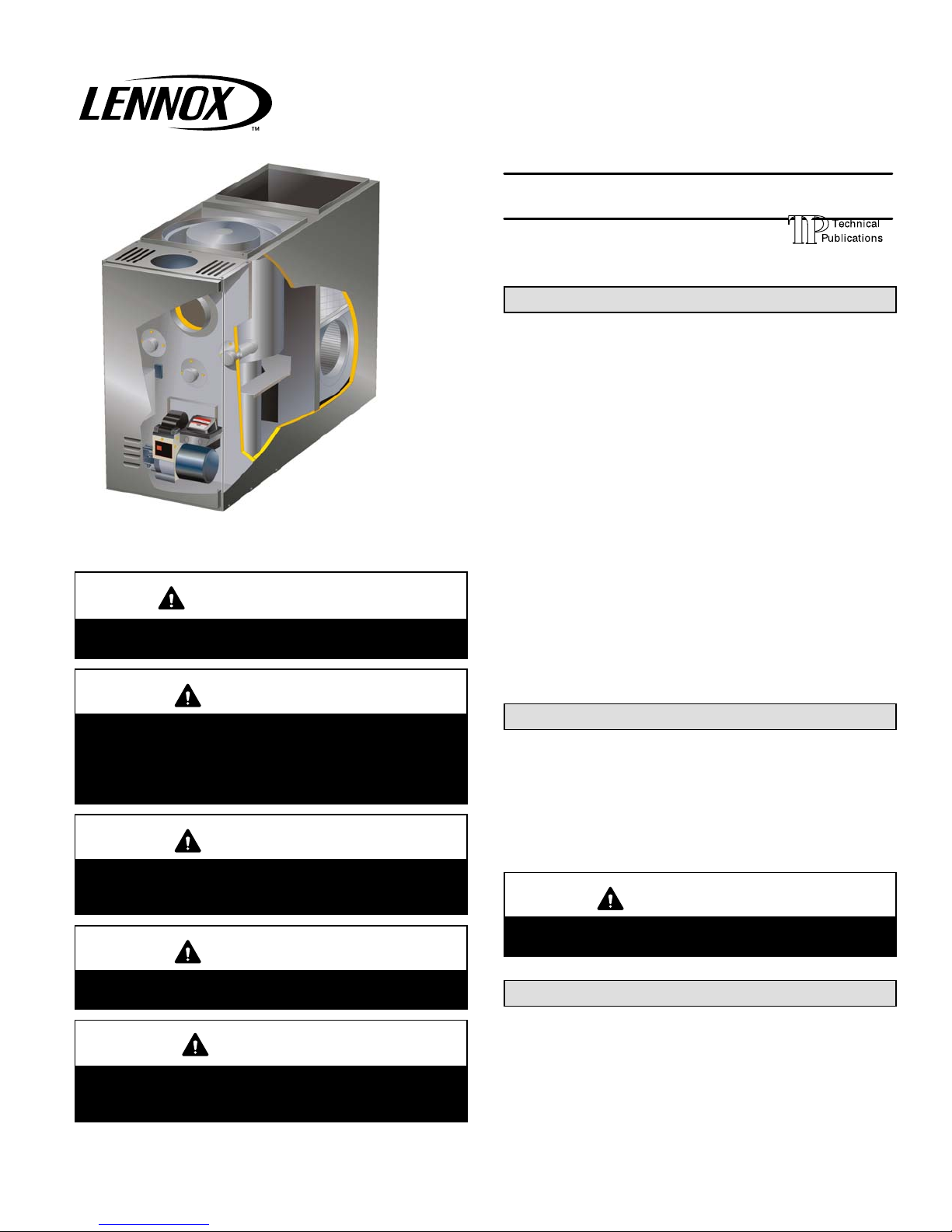
Front
Flue Model
Shown
RETAIN THESE INSTRUCTIONS
FOR FUTURE REFERENCE
IMPORTANT
This unit must be serviced annually by a licensed
professional technician, or equivalent.
WARNING
Improper installation, adjustment, alteration, service, or maintenance can cause injury or property
damage. Refer to this manual. For assistance or
additional information, consult a licensed professional installer, or equivalent, or service agency.
WARNING
Do not store or use gasoline or other flammable vapors and liquids in the vicinity of this or any other appliance.
CAUTION
When venting this appliance, keep vent terminal free
of snow, ice and debris.
CAUTION
As with any mechanical equipment, personal injury
can result from contact with sharp sheet metal
edges. Be careful when you handle this equipment.
INSTALLATION
INSTRUCTIONS
SLO183BV SERIES UNITS
OIL UNITS
506905−01
04/2012
Table of Contents
General 1. . . . . . . . . . . . . . . . . . . . . . . . . . . . . . . . . . . . .
Shipping & Packing List 1. . . . . . . . . . . . . . . . . . . . . . .
SLO183BV Unit Dimensions 2. . . . . . . . . . . . . . . . . . .
SLO183BV Start−Up & Performance Check List 2. .
SLO183BV Unit Parts Arrangement 3. . . . . . . . . . . . .
SLO183BV AFG Burner Parts Arrangement 3. . . . .
Requirements 4. . . . . . . . . . . . . . . . . . . . . . . . . . . . . . . .
Combustion and Ventilation Air 5. . . . . . . . . . . . . . . . .
Locate & Level Unit 6. . . . . . . . . . . . . . . . . . . . . . . . . . .
Nozzle Adjustments 7. . . . . . . . . . . . . . . . . . . . . . . . . .
Indoor Coil Placement 8. . . . . . . . . . . . . . . . . . . . . . . .
Venting 8. . . . . . . . . . . . . . . . . . . . . . . . . . . . . . . . . . . . .
Flue Connections 10. . . . . . . . . . . . . . . . . . . . . . . . . . .
Supply & Return Air Plenums 11. . . . . . . . . . . . . . . . .
Oil Supply Line Sizing 11. . . . . . . . . . . . . . . . . . . . . . .
Oil Supply Line and Filter Connections 13. . . . . . . . .
Leak Check 13. . . . . . . . . . . . . . . . . . . . . . . . . . . . . . . .
Electrical Wiring 13. . . . . . . . . . . . . . . . . . . . . . . . . . . . .
Blower Control (A54) 17. . . . . . . . . . . . . . . . . . . . . . . .
Start−Up & Adjustment 19. . . . . . . . . . . . . . . . . . . . . . .
Service 21. . . . . . . . . . . . . . . . . . . . . . . . . . . . . . . . . . . .
GeniSyst Primary Control 22. . . . . . . . . . . . . . . . . . .
Heating Sequence 24. . . . . . . . . . . . . . . . . . . . . . . . . . .
Troubleshooting 24. . . . . . . . . . . . . . . . . . . . . . . . . . . . .
General
These instructions are intended as a general guide and do
not supersede local codes in any way. Only licensed professional technicians, or equivalent, can install and service
the Dave Lennox Signature
®
Collection SLO183BV oil furnaces. In Canada, refer to CSA B139 for recommended
installation procedures. Consult authorities who have jurisdiction before installation.
CAUTION
Never burn garbage or paper in the heating system.
Never leave papers near or around the unit.
Shipping & Packing List
1 − Assembled oil furnace
1 − Barometric draft control
1 − Oil nozzle (used with SLO183BV−114 and −150 only)
Check the components for shipping damage. If you find any
damage, immediately contact the last carrier.
Litho U.S.A.
Page 2
Page 2
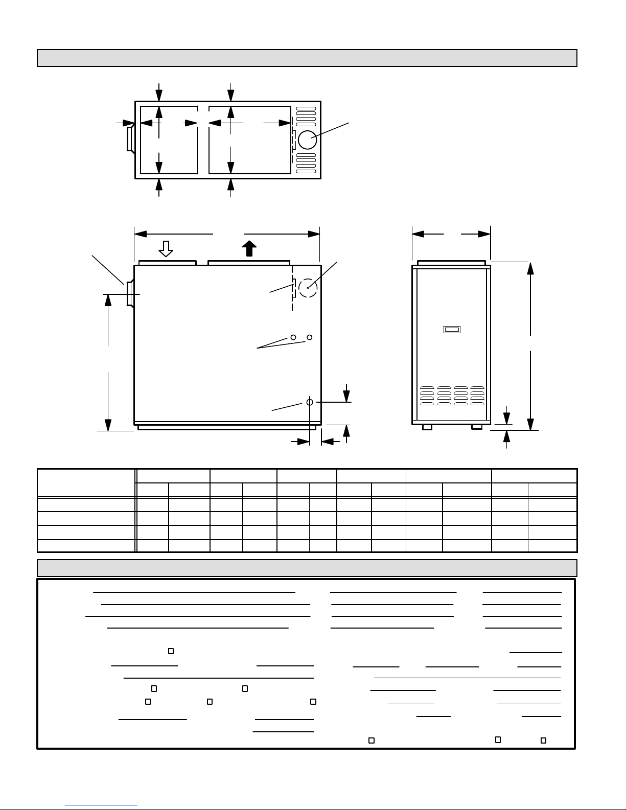
SLO183BV Unit Dimensions − Inches (mm)
FLUE CONNECTION
SLO183BR101/114V42
1
(25)
2−1/2
(64)
RETURN
AIR
OPENING
SUPPLY
AIR
OPENING
OIL PIPING INLET
(Both Sides)
ELECTRICAL INLETS
(Right Side Only)
TOP VIEW
SIDE VIEW FRONT VIEW
A
E
D
E
3/4
(19)
FLUE CONNECTION
SLO183BF101/114V42 &
SLO183B5F135/150V60
(On Heat Exchanger)
AIR FLOW
AIR FLOW
3/4
(19)
3/4
(19)
3/4
(19)
1-1/2
(38)
3-1/4
(83)
5−1/4
(133)
B
C
FG
SIDE
FLUE OUTLET
CENTERING HOLE
(Field−Fabricate
Either Side)
TOP FLUE
OUTLET
Model No.
A B C D E x F (Supply) E x G (Return)
in. mm in. mm in. mm in. mm in. mm in. mm
SLO183BF101/114V42 19-1/2 495 37 940 52−1/2 1334 27 686 18 x 21 457 x 533 18 x 16 457 x 406
SLO183BR101/114V42 19-1/2 495 37 940 52−1/2 1334 27 686 18 x 21 457 x 533 18 x 16 457 x 406
SLO183BF135/150V60 22-1/2 572 37 940 52−1/2 1334 27 686 21 x 21 533 x 533 21 x 16 533 x 406
SLO183BR135/150V60 22-1/2 572 37 940 52−1/2 1334 27 686 21 x 21 533 x 533 21 x 16 533 x 406
SLO183BV Start−Up & Performance Check List
Filter Clean & Secure?
Supply Voltage
Electrical Connections Tight?
Job Name
Job Location
Installer
Unit Model No.
Oil Pump Pressure [recommended minimum 140 psi]
Job No.
City
City
Serial No.
Date
State
Serviceman
Draft Reading (recommended .03−.04 inches w.c.)
Flue Connections Tight?
HEATING SECTION
THERMOSTAT
Calibrated? Heat Anticipator Properly Set? Level?
Blower Motor Amps
Blower Motor H.P.
Piping Connections Tight?
Vent Clear?
State
Temperature RiseExternal Static Pressure
Net Stack Temp
Burner Model No.
Serial Number
All Valves Open?
PROPER DRAFT
% CO
2
% O
2
ppm CO
Stack Draft Overfire Draft
Ambient Temp
Smoke Test
Page 3
Page 3
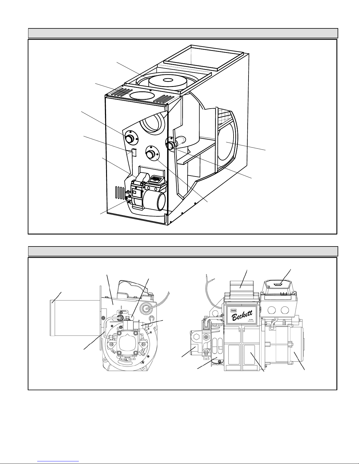
SLO183BV Unit Parts Arrangement
Figure 1
Limit Switch
ST9103A Control −− A15
BeckettR AFG Burner
Blower
(Variable Speed Motor
on Other Side)
Observation Port
Clean−Out Port
Flue Opening
Heat Exchanger
Blower Control
A54
(Not Visible −−
Located on
blower housing)
Clean−Out Port
SLO183BV AFG Burner Parts Arrangement
ESCUTCHEON
PLATE
MAIN
HOUSING
HEAT
SHIELD
BURNER CONTROL
(with Reset Button)
OIL DELAY
VALV E
AIR TUBE WITH
ELECTRODE
ASSEMBLY AND
NOZZLE INSIDE
BLOWER WHEEL
WITH AIR GUIDE
(Inside housing)
COPPER OIL
TUBE
BLOWER
MOTOR
IGNITER
AIR BAND AND
AIR SHUTTER
Figure 2
FUEL PUMP
Page 4
Page 4
Requirements
WARNING
Product contains fiberglass wool.
Disturbing the insulation in this product during
installation, maintenance, or repair will expose you
to fiberglass wool dust. Breathing this may cause
lung cancer. (Fiberglass wool is known to the State
of California to cause cancer.)
Fiberglass wool may also cause respiratory, skin,
and eye irritation.
To reduce exposure to this substance or for further
information, consult material safety data sheets
available from address shown below, or contact your
supervisor.
Lennox Industries Inc.
P.O. Box 799900
Dallas, TX 75379−9900
Installation of Lennox oil−fired furnaces must conform with
the National Fire Protection Association Standard for the
Installation of Oil Burning Equipment, NFPA No. 31, the
National Electrical Code, ANSI/NFPA No.70 (in the
U.S.A.), CSA Standard CAN/CSA−B139 (in Canada),
Installation Code for Oil Burning Equipment, the Canadian
Electrical Code Part1, CSA 22.1 (Canada), the recommendations of the National Environmental Systems Contractors Association and any state or provincial laws or local ordinances. Authorities having jurisdiction should be
consulted before installation. Such applicable regulations
or requirements take precedence over general instructions
in this manual.
Chimneys and chimney connectors must be of the type and
construction outlined in section 160 of NFPA No. 31.
Air for combustion and ventilation must conform to standards outlined in section 140 of NFPA No. 31 or, in Canada,
CSA Standard B139. When installing SLO183B units in
confined spaces such as utility rooms, two combustion air
openings are required. Dimensions of combustion air
openings are shown in table 1. One opening shall be below
burner level and the other opening shall be no more than 6"
(152 mm) from the room’s ceiling.
The combustion air opening should provide a minimum free
area one-half square inch per 1,000 Btu per hour input. This
combustion air should be brought into the area containing the
furnace below the level of the furnace burner.
IMPORTANT
An opening to the outside for combustion air is
strongly recommended, especially in new homes.
Refer to table 1 or the unit plate for specific combustion air opening dimensions.
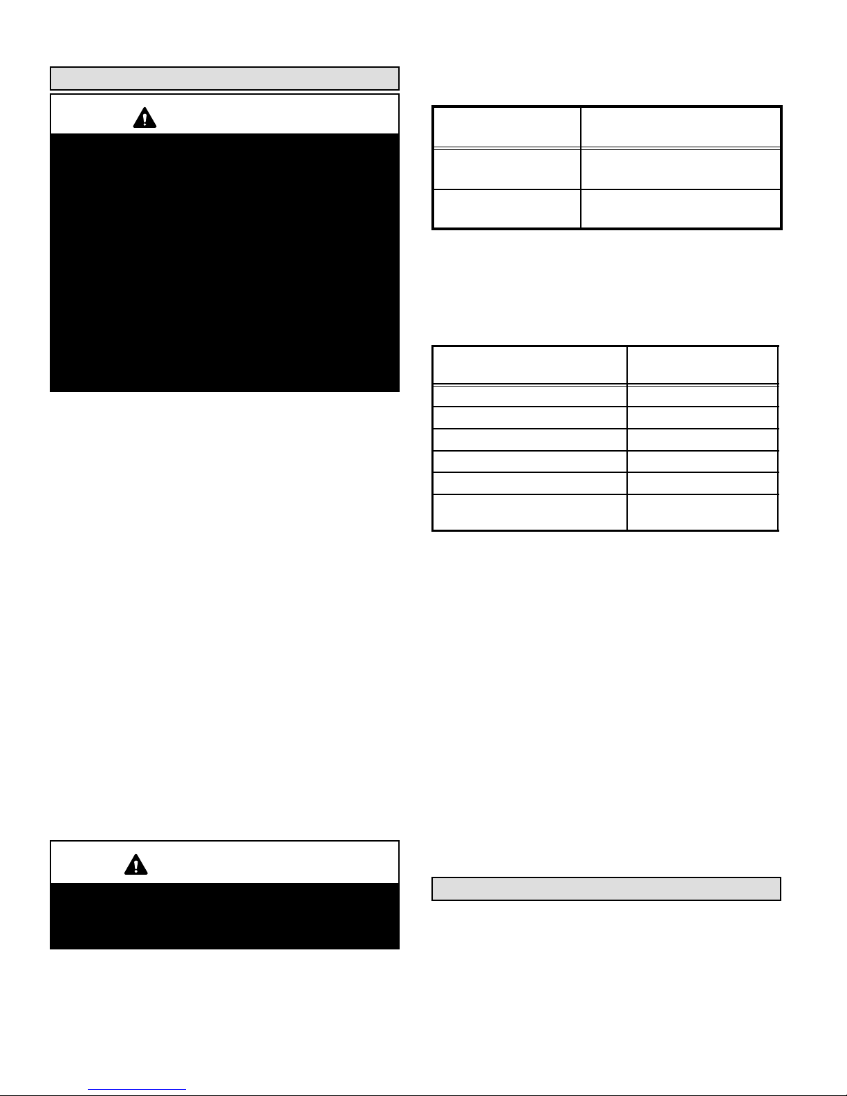
Table 1
Combustion Air Opening Dimensions
Model No.
Combustion Air Opening
Dimensions (2 required)
SLO183BF101/114V
SLO183BR101/114V
10" X 20" (254 mm X 508 mm)
SLO183BF135/150V
SLO183BR135/150V
11" X 22" (279 mm X 559 mm)
This unit is approved for use on combustible flooring and for
clearances to combustible material as listed on unit rating
plate and in table 2. Unit service and accessibility clearances
take precedence over fire protection clearances.
Table 2
Installation Clearances
Clearances
All Unit Sizes
inches (mm)
top of plenum and duct 2 (51)
plenum sides 3 (76)
sides* 6 (152)
rear 24 (610)
front 4 (102)
flue pipe measured vertical**
(measured from above)
9 (229)
NOTE−Service access clearance must be maintained.
*Clearance to allow inspection of furnace and flue connector
shall be provided. 24" (610 mm) at rear and on one side of furnace should
be allowed for cleaning and service of the blower.
**Minimum clearance shown for flue pipe may be reduced by using special
protection as provided by local building codes and the National Fire
Protection Association Standards and CSA 189.
NOTE − When service clearances are greater than fire
protection clearances, service clearances take precedence.
Obtain a temperature rise within the range listed in table 8
in the Start-Up section of this manual.
When installed, furnace must be electrically grounded in
accordance with local codes or, in the absence of local
codes, with the current National Electric Code, ANSI/NFPA
No. 70, or Canadian Electric Code (CEC) if an external
electrical source is utilized.
Field wiring connection with unit must meet or exceed
specifications of type T wire and withstand a 63_F (17_C)
temperature rise.
Notice to Home Owner
This furnace is equipped with safety devices that protect
you and your property. If one or more of these devices is
activated, furnace operation will stop. If your home is left
unattended for an extended period of time, equipment operation must be checked periodically. If this is not possible,
the water supply to the house should be shut off and the
pipes should be drained. This will prevent problems associated with a NO HEAT condition (frozen pipes, etc.)
Page 5
Page 5
Combustion and Ventilation Air
Homes built with energy conservation in mind use tight
construction practices. These houses are sealed so well
that it becomes necessary to provide a means of bringing in
air from outside for combustion. Also, exhaust fans, appliance vents, chimneys and fireplaces force additional air
that could be used for combustion out of the house. Unless
outside air is brought into the home for combustion, negative pressure (pressure outside is greater than inside pressure) will build to the point that a down draft can occur in the
furnace vent pipe or chimney. Combustion gases enter the
living space creating a potentially dangerous situation. Negative pressure may also interfere with proper combustion,
causing sooting within the heat exchanger.
The importance of the previous paragraph cannot be overstated. Users may inadvertently block fresh air intakes after
installation.
In the absence of local codes concerning air for combustion and ventilation, the following section outlines guidelines and recommends procedures for operating oil furnaces in a manner that ensures efficient and safe
operation. Special consideration must be given to combustion air needs as well as requirements for exhaust vents
and oil piping.
Combustion Air Requirements
CAUTION
Insufficient combustion air can cause headaches,
nausea, dizziness or asphyxiation. It will also cause
excess water in the heat exchanger resulting in rusting and premature heat exchanger failure. It can also
cause property damage.
All oil-fired appliances require air to be used for the combustion process. If sufficient amounts of combustion air are
not available, the furnace or other appliance will operate in
an inefficient and unsafe manner. Enough air must be provided to meet the needs of all fuel-burning appliances, as
well as appliances such as exhaust fans which force air out
of the home. When fireplaces, exhaust fans, or clothes dryers are used at the same time as the furnace, much more
air is required to ensure proper combustion and to prevent
a down-draft situation. Insufficient amounts of air also
cause incomplete combustion which can result in sooting.
Requirements for providing air for combustion and ventilation depend largely on whether the furnace is installed in an
unconfined or confined space.
Unconfined Space
An unconfined space is an area such as a basement or
large equipment room with a volume greater than 50 cubic
feet (1.4 cubic meters) per 1,000 Btu (293 W) per hour of
the combined input rating of all appliances installed in that
space. This space also includes adjacent rooms which are
not separated by a door. Though an area may appear to be
unconfined, it might be necessary to bring in outdoor air for
combustion if the structure does not provide enough air by
infiltration. If the furnace is located in a building of tight
construction with weather stripping and caulking around
the windows and doors, follow the procedures outlined for
using air from the outside for combustion and ventilation.
Confined Space
A confined space is an area with volume less than 50 cubic
feet (1.4 cubic meters) per 1,000 Btu (293 W) per hour of
the combined input rating of all appliances installed in that
space. This definition includes furnace closets or small
equipment rooms.
When the furnace is installed so that supply ducts carry air
circulated by the furnace to areas outside the space containing the furnace, the return air must be handled by ducts
which are sealed to the furnace casing and which terminate
outside the space containing the furnace. This is especially
important when the furnace is mounted on a platform in a
confined space such as a closet or small equipment room.
Even a small leak around the base of the unit at the platform
or at the return air duct connection can cause a potentially
dangerous negative pressure condition. Air for combustion
and ventilation can be brought into the confined space either from inside the building or from outside.
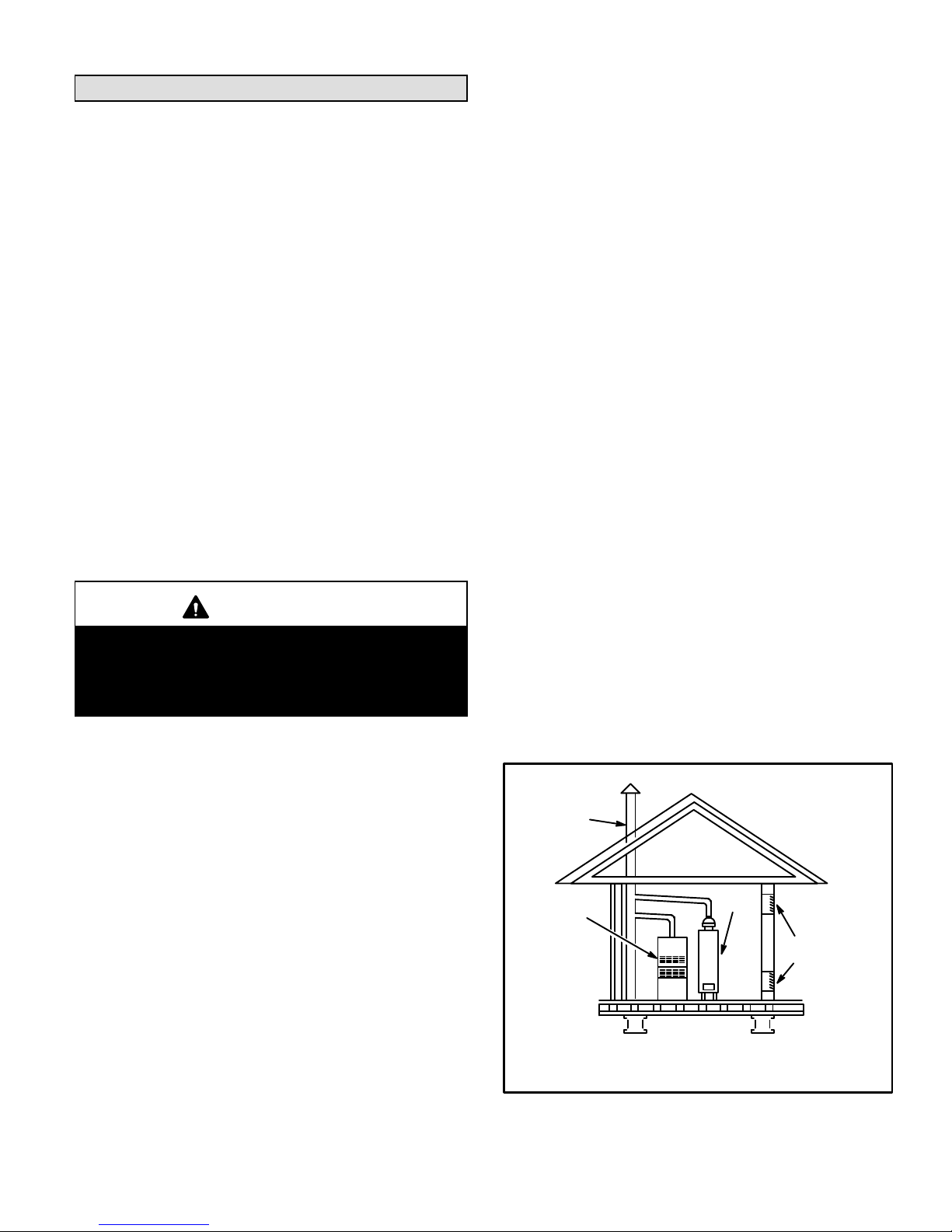
Air from an Adjacent Space
If the confined space housing the furnace adjoins space
categorized as unconfined, air can be brought in by providing two permanent openings between the two spaces.
Each opening must have a minimum free area of 1 square
inch
(6.4 square centimeters) per 1,000 Btu (293 W) per
hour of the total input rating of all fuel-fired equipment in the
confined space. Each opening must be at least 100 square
inches (614.5 square centimeters). One opening shall be
within 12" (305 mm) of the top of the enclosure and one
opening within 12" (305 mm) of the bottom (See figure 3).
Equipment In Confined Space
All Air From Inside
Chimney or
Oil Ven
t
Water
Heater
Openings
(To Adjacent Room)
Figure 3
NOTE−Each opening shall have a free area of at least 1 square inch
(6.4 square centimeters) per 1,000 Btu (293 W) per hour of the total
input rating of all equipment in the enclosure, but not less than 100
square inches
(614.5 square centimeters).
Oil
Furnace
Page 6
Page 6
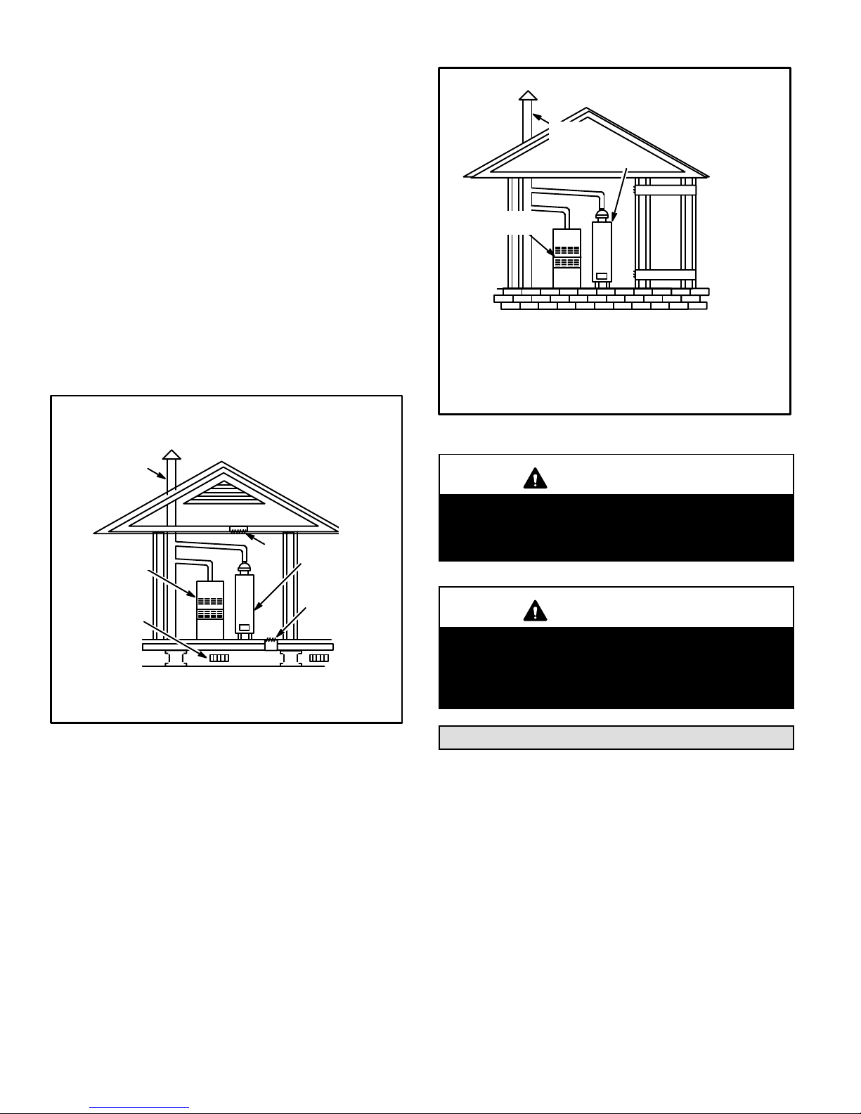
Air from Outside
If air from outside is brought in for combustion and ventilation, the confined space shall be provided with two permanent openings. One opening shall be within 12" (305 mm)
of the top of the enclosure and one within 12" (305 mm) of
the bottom. These openings must communicate directly or
by ducts with the outdoors or spaces (crawl or attic) that
freely communicate with the outdoors or indirectly through
vertical ducts. Each opening shall have a minimum free
area of 1 square inch (6.4 square centimeters) per 4,000
Btu (1172 W) per hour of total input rating of all equipment
in the enclosure. (See figure 4.) When communicating with
the outdoors through horizontal ducts, each opening shall
have a minimum free area of 1 square inch (6.4 square
centimeters) per 2,000 Btu (586 W) per total input rating of
all equipment in the enclosure (See figure 5).
Ventilation
Louvers
(For unheated
crawl space)
Outlet
Ai
r
Equipment In Confined Space
All Air From Outside
(Inlet Air from Crawl Space and Outlet Air to
Ventilated Attic)
NOTE−The inlet and outlet air openings shall each have a free area of
at least one square inch (6.4 square centimeters) per 4,000 Btu (1172
W) per hour of the total input rating of all equipment in the enclosure.
Ventilation Louvers
(Each End Of Attic)
Water
Heater
Inlet
Air
Chimney or
Oil Vent
Figure 4
Oil
Furnace
When ducts are used, they shall be of the same cross−sectional area as the free area of the openings to which they
connect. The minimum dimension of rectangular air ducts
shall be no less than 3" (76 mm). In calculating free area,
the blocking effect of louvers, grilles, or screens must be
considered. If the design and free area of protective covering is not known for calculating the size opening required, it
may be assumed that wood louvers will have 20 to 25 percent free area and metal louvers and grilles will have 60 to
75 percent free area. Louvers and grilles must be fixed in
the open position or interlocked with the equipment so that
they are opened automatically during equipment operation.
Equipment In Confined Space
All Air From Outside
Outlet Air
Inlet Air
Water
Heate
r
Chimney
Or Oil
Vent
Figure 5
NOTE−Each air duct opening shall have a free area of at least one
square inch (6.4 square centimeters) per 2,000 Btu (586 W) per hour
of the total input rating of all equipment in the enclosure. If the equipment room is located against an outside wall and the air openings
communicate directly with the outdoors, each opening shall have a
free area of at least one square inch (6.4 square centimeters) per
4,000 Btu (1172 W) per hour of the total input rating of all other equipment in the enclosure.
Oil
Furnace
CAUTION
Combustion air openings in the front of the furnace
must be kept free of obstructions. Any obstruction
will cause improper burner operation and may result
in a fire hazard or injury.
CAUTION
The barometric draft control shall be in the same atmospheric pressure zone as the combustion air inlet
to the furnace. Deviation from this practice will cause
improper burner operation and may result in a fire
hazard or injury.
Locate & Level the Unit
The compact design of this furnace makes it ideal for a
basement or utility room installation. Choose a central
location for the furnace so that supply air ducts approximately the same length. This will allow each room to receive the proper amount of heat. The furnace should be
placed within 10 feet of the chimney, so that the flue connection to the chimney will be of minimum length and have
a minimum number of elbows.
1 − Set the unit in desired location keeping in mind the
clearances listed in table 2. Also keep in mind oil supply connections, electrical supply, flue connections
and sufficient clearance for installing and servicing
unit.
Page 7
Page 7
2 − Level the unit from side−to−side and from front−to−rear.
If the furnace is not level, place fireproof wedges or
shims between the low side of the furnace and the
floor. Make sure the weight of the furnace is distributed
evenly on all four corners. Strain on sides of cabinet
may occur if furnace weight is not evenly distributed.
This strain can cause cracking and popping noises.
Adjustments
Neither the nozzle setting nor the air adjustments are factory set. The furnace is fire−tested and the limit control is
checked to make sure it functions properly; no factory settings are made. During installation, the furnace must be adjusted to ensure proper operation. The installing dealer/
contractor must have and use proper test equipment in
order to correctly adjust the oil furnace. Proper testing
equipment is required to ensure correct operation of the
unit. The use of test equipment is more critical than ever
due to tighter tolerances needed to keep the furnace operating efficiently.
Among the required test equipment for an oil furnace, the
proper combustion test kit should contain the following:
D Draft gauge
D CO
2
or O2 Analyzer
D Smoke tester
D Pressure gauge
D High temperature thermometer
D Oil vacuum gauge
D Beckett T−501 or Z−2000 nozzle gauge
D Knowledge of proper test equipment operation
CAUTION
Improper nozzle and/or air adjustment of this unit
may result in sooting problems. Refer to the following section for correct adjustment procedures.
Nozzle Adjustment
Proper adjustment of the nozzle assembly is critical. Before
the flue pipe and oil lines are installed, the nozzle assembly
must be checked for proper depth and alignment. You must
remove the entire burner assembly (not just the nozzle) from
the furnace to check the nozzle depth and alignment. The
smaller sized firing nozzle has been factory−installed. This
should be verified by the installer. A larger nozzle has been
provided in the bag assembly for use with SLO183BV114
and 150 units. Inspect the spark transformer leads also to ensure they are still attached to the electrodes.
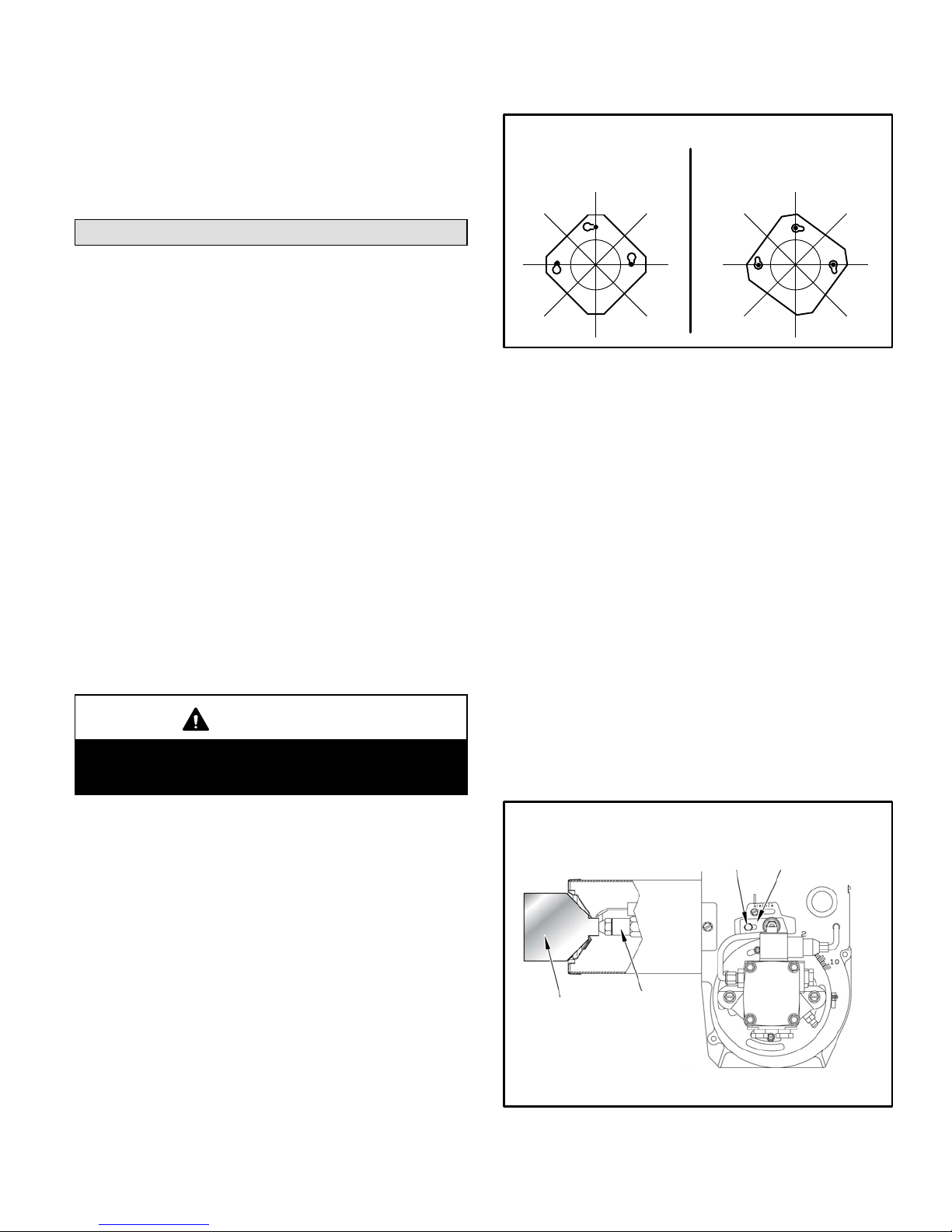
The burner assembly is attached to the vestibule panel by
three nuts. Slots are provided in the mounting flange for removing the burner assembly from the vestibule. Loosen the
nuts and turn the whole burner assembly clockwise (figure
6) to remove the entire burner assembly from the furnace.
There is adequate wire to remove the burner without discon-
necting wires. Once removed, turn the burner around in the
vest panel area.
Figure 6
SLO183BV Series Burner Removal
First, loosen three nuts which
attach burner to vest panel.
Next, rotate burner clockwise
on slots then pull toward you.
To correctly check and adjust the nozzle depth and alignment, use the Beckett T−501 or Z−2000 gauge.
To check the oil nozzle depth, insert the small end of the
gauge into the end of the cone and measure from the flat of
the end cone to the face of the nozzle. When nozzle depth
is correct, the tip of the nozzle should just touch the end of
the gauge. Refer to the illustration sheet provided with the
gauge. Note that the scale side of the gauge is not used for
this purpose. If necessary, loosen the escutcheon plate securing screw and slide the entire nozzle assembly forward
or backward within the air tube (figure 7). Re−secure escutcheon plate screw when adjustment is completed.
To check nozzle alignment, again insert the small end of
gauge into the end cone and measure the nozzle and
electrode alignment against the center lines marked on
the gauge (again refer to enclosed illustration sheet). If
the nozzle is not centered, but found to be too far left or
right, a new nozzle assembly will need to be ordered. Do
not attempt to adjust by bending the 90 degree elbow in
the oil line.
Take care to properly re−install burner assembly when
nozzle adjustment has been completed.
Figure 7
Beckett Oil Burner Nozzle Adjustment
Burner must be removed from
furnace for this procedure.
1
2
T−501 Gauge
Escutcheon Plate
To Adjust Nozzle
1−Loosen escutcheon plate screw.
2−Slide entire nozzle/electrode assembly back and forth inside air
tube until nozzle just touches gauge.
Page 8

Page 8
Indoor Coil Placement
In cooling / heat pump applications, Lennox recommends that
the indoor coil be installed at least 4 inches above the top of the
furnace cabinet to allow proper airflow. If coil cabinet does not
provide proper clearance, use field−fabricated transition.
Venting
WARNING
Combustion air openings in front of the furnace must
be kept free of obstructions. Any obstruction will
cause improper burner operation and may result in
a fire hazard.
WARNING
The barometric draft control shall be in the same atmospheric pressure zone as the combustion air inlet
to the furnace. Deviation from this practice will cause
improper burner operation and may result in a fire
hazard.
CAUTION
Do not store combustible materials near the furnace
or supply air ducts. The material (such as paint, motor oil, gasoline, paint thinner, etc.) may ignite by
spontaneous combustion creating a fire hazard.
WARNING
This furnace is certified for use with type L" vent.
B" vent must not be used with oil furnaces.
Prior to installation of unit, make a thorough inspection of the
chimney to determine whether repairs are necessary. Make
sure the chimney is properly constructed and sized according to the requirements of the National Fire Protection Association. The smallest dimensions of the chimney should be
at least equal to the diameter of the furnace vent connector.
Make sure the chimney will produce a steady draft sufficient
to remove all the products of combustion from the furnace. A
draft of at least .04" w.c. (9.9 Pa) is required during burner
operation.
1 − Local building codes may have more stringent installa-
tion requirements and should be consulted before
installation of unit.
2 − The vent connector should be as short as possible to
do the job.
3 − The vent connector should not be smaller than the out-
let diameter of the vent outlet of the furnace.
4 − Pipe should be at least 24 gauge galvanized.
5 − Single wall vent pipe should not run outside or through
any unconditioned space.
6 − Chimney should extend 3 feet (0.9 m) above highest
point where the vent passes through the roof, and 2
feet (0.6 m) higher than any portion of a building within
a horizontal distance of 10 feet (3 m).
7 − The vent must not pass through a floor or ceiling.
Clearances to single wall vent pipe should be no less
than 6" (152 mm); more if local codes require it.
8 − The vent may pass through a wall where provisions
have been made for a thimble as specified in the Standards of the National Board of Fire Underwriters. See figure 8.
Wall Thimble
Figure 8
Thimble
Vent Pipe
Combustible
Wall
Page 9
Page 9
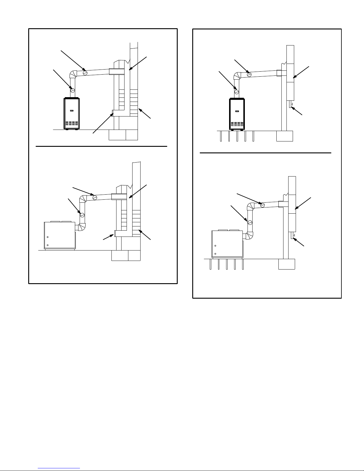
Front Flue / Masonry Chimney
Rear Flue / Masonry Chimney
Liner
Barometric
Draft
Control*
(in either
location)
Clean Out
Liner
Masonry
Chimney
Figure 9
*Barometric draft control may be installed in either vertical or
horizontal section of flue pipe no less than 12" and no more than
18" from furnace flue outlet.
Barometric Draft
Control*
(in either location)
Clean Out
Masonry
Chimney
9 − The vent pipe should slope upward toward the chim-
ney on horizontal run at least 1/4 inch (6 mm) to the
foot (0.3 m) and should be supported by something
other than the furnace, such as isolation hangers. See
figure 9.
10 − Extend the vent pipe into the chimney so that it is flush
with the inside of the chimney liner. Seal the joint between the pipe and the liner.
11 − The furnace shall be connected to either a factory−built
chimney or vent which complies with a recognized
standard, or to a masonry or concrete chimney which
has been lined with a material acceptable to the authority having jurisdiction.
12 − When two or more appliances vent into a common
vent, the area of the common vent should not be less
than the area of the largest vent or vent connection
plus 50% of the area of the additional vent or vent connection. Chimney must be able to sufficiently vent all
appliances operating at the same time.
Front Flue / Factory−Built Chimney
Rear Flue / Factory−Built Chimney
Figure 10
Condensate
Drain
Factory−
Built
Chimney
Barometric Draft
Control*
(in either location)
Barometric Draft
Control*
(in either location)
Factory−
Built
Chimney
Condensate
Drain
*Barometric draft control may be installed in either vertical or
horizontal section of flue pipe no less than 12" and no more than
18" from furnace flue outlet.
13 − The vent pipe shall not be connected to a chimney
vent serving a solid fuel appliance or any mechanical
draft system.
14 − All unused chimney openings should be closed.
15 − All vent pipe run through unconditioned areas or out-
side shall be constructed of factory built chimney sections. See figure 10.
16 − Where condensation of vent gas is apparent, the vent
should be repaired or replaced. Accumulation of condensation in the vent is unacceptable.
17 − Vent connectors serving this appliance shall not be
connected into any portion of mechanical draft systems operating under positive pressure.
18 − Keep the area around the vent terminal free of snow,
ice and debris.
Page 10

Page 10
NOTE − If vent pipe needs to exit from side of cabinet,
use the pilot hole (located on either side of the unit) to
cut a 6" (152 mm) round hole. Attach finishing plate
(provided) with four sheet metal screws to cover rough
edges.
Removal of Unit from Common Venting System
In the event that an existing furnace is removed from a
venting system commonly run with separate appliances,
the venting system is likely to be too large to properly vent
the remaining attached appliances. The following test
should be conducted while each appliance is in operation
and the other appliances not in operation remain connected to the common venting system. If venting system
has been installed improperly, the system must be corrected as outlined in the previous section.
1 − Seal any unused openings in the common venting
system.
2 − Visually inspect venting system for proper size and
horizontal pitch and determine there is no blockage or
restriction, leakage, corrosion or other deficiencies
which could cause an unsafe condition.
3 − Insofar as is practical, close all building doors and win-
dows and all doors between the space in which the appliances remaining connected to the common venting
system are located and other spaces of the building.
Turn on clothes dryers and any appliances not connected to the common venting system. Turn on any
exhaust fans, such as range hoods and bathroom exhausts, so they will operate at maximum speed. Do not
operate a summer exhaust fan. Close fireplace dampers.
4 − Following the lighting instruction on the unit, place the
appliance being inspected in operation. Adjust thermostat so appliance will operate continuously.
5 − Test for spillage using a draft gauge.
6 − After it has been determined that each appliance re-
maining connected to the common venting system
properly vents when tested as outlined above, return
doors, windows, exhaust fans, fireplace dampers and
any other fuel burning appliance to its previous condition of use.
7 − If improper venting is observed during any of the
above tests, the common venting system must be corrected.
Flue Connections
IMPORTANT
When flue pipe is installed at less than minimum
clearance listed in table 2, radiation shields must be
installed. See figure 11.
For front flue models, the enclosed exhaust pipe ring may
be used for pipe to exit the left or right side of cabinet. Center line marks are provided in cabinet.
Use 24 gauge or heavier galvanized smoke pipe and fittings to connect furnace to vent. Connect flue pipe to chimney using the least number of elbows and angles possible.
Flue pipe or vent connector must be inserted into the chimney so that it is flush with the inside of the vent liner. No reduction in diameter of flue pipe is acceptable. It is best to
have flue pipe as short and direct as possible. Where two or
more appliances vent into a common flue, the area of the
common flue should be at least equal to the area of the largest flue or vent connector, plus 50% of the area of any additional flues or vent connectors. Install the barometric draft
control (provided) and flue pipe according to instructions
packed with control.
Inspect flue pipe annually. Clean soot or ash from flue pipe,
if necessary. If pipe is rusted, replace.
Page 11

Page 11
A
1" (25 mm)
min
A
Figure 11
combustible
material
Radiation Shield Installation
SLO183B
unit
(top)
SLO183B
unit
(front)
radiation
shields
flue
pipe
B
unit
cabinet
NOTE 1−Radiation shields must be constructed of 24 gauge sheet
metal minimum.
NOTE 2−Radiation shields required when A is less than 9" (229 mm).
NOTE 3−Radiation shields should extend from the top of the unit to
the top of the flue pipe.
noncombustible
spacers
radiation shields
(see note 1)
12" (305 mm)
min
7" (178 mm)
min
see note 2
see note 3
Barometric Draft Control Installation
Install the provided barometric draft control in the flue pipe
at least 12 inches beyond the furnace flue outlet to provide
space for flue gas sampling. The barometric draft control
may be installed in either vertical or horizontal sections of
the flue pipe; however, it should be positioned no more
than 18" beyond the furnace flue outlet. Follow the instructions packed with the barometric draft control.
Alternate Side Flue Connections
The vent pipe may exit the top or sides of the cabinet. A
hole is provided in the top cap for top exit. For side exit, locate the center hole punched in the side of the cabinet. See
unit dimensions on page 2. Using it as the center point, cut
a 6 inch (152 mm) round hole in the cabinet’s side. Install
the barometric draft control within 18 inches of the furnace
flue outlet. Attach the provided finishing plate to cover
rough edges.
Supply & Return Air Plenums
Secure return air plenum to unit using sheet metal screws.
NOTE − The following are suggested procedures that
should be followed when installing the supply air plenum.
1 − Use sealing strips of fiberglass.
2 − In all cases, the plenum should be secured to furnace
or evaporator cabinet with sheet metal screws.
3 − Install supply and return air ducts as desired.
Oil Supply Line Sizing
Ensure that the restrictions of the piping system, plus any
lift involved, do not exceed the capability of the oil pump.
Use the following guidelines and table 5 when determining
whether to use a single−or two−stage oil pump.
One−Pipe System
When using a one−pipe system with the oil tank above the
burner, or a one−pipe system with no more than an 8−ft.
(2.4m) lift and a vacuum of 6" (152 mm) Hg or less, a single−
stage fuel pump with a supply line should be adequate without a separate return line. See figure 12. Manual bleeding
of the fuel pump is required on initial start up. Failure to
bleed air from the oil pump could result in an air lock/oil
starvation condition.
NOTE − As an extra precaution, cycle heating on and off ten
times after bleeding air from the oil pump. This will eliminate air in the gun assembly.
To determine pipe sizing for a one−pipe application, refer to
table 3.
Figure 12
Oil Piping
Air Vent
Fill
Pipe
Oil
Tank
Fuel
Pump
Aux
Filter
Shut−Off
Valve
8 ft (2.4 m)
Maximum
Lift
One-Pipe System
Table 3
One−Pipe Oil Line Sizing
Line Length
Pipe Diameter (OD Tubing)
0−50’ (15 m) 3/8" (10 mm)
51−100’ (15 m) 1/2" (12 mm)
Two−Pipe System
When using a two−pipe system with the oil tank below the
level of the burner, a single−stage fuel pump should be used
in lift conditions of up to 10 feet (3 m) and/or a vacuum of
12" Hg or less. See figure 13. Use a two−stage fuel pump
when lift exceeds 10 feet (3 m) and/or the vacuum is in the
range of 12" Hg to 17" Hg.
Page 12

Page 12
Both conditions require that you use a two−pipe system,
which consists of a return line that purges the fuel pump of
air by returning it to the tank. To determine the run and lift for
piping, refer to table 4.
Figure 13
Oil Piping
ООООООООООООО
ООООООООООООО
ООООООООООООО
ООООООООООООО
Fuel
Pump
Aux
Filter
Return
pipe
Fill
Pipe
Air Vent
Oil
Tank
Inlet
Return
Pipe
H
3"−4"
(76 mm −102 mm)
R
Outside tank fuel pump above bottom of tank
Two-Pipe System
Use continuous lengths of heavy wall copper tubing or
steel pipe for oil supply pipe. Install oil supply pipe under
floor or near walls to protect it from damage. Avoid running
pipes along joists or reverberating surfaces. Always use
flare fittings. All fittings must be accessible. Do not use
compression fittings.
IMPORTANT
Both oil supply and return pipes must be submerged
in oil in the supply tank.
Table 4
Two−Pipe Maximum Pipe Length (H + R)
Lift H"
3450 RPM − 3 GPH (11.4 LPH)
3/8" (10 mm) OD
Tubing
1/2" (12 mm) OD
Tubing
Single
Stage
Two
Stage
Single
Stage
Two
Stage
0’
(0.0 m)
84’
(25.6 m)
93’
(28.3 m)
100’
(30.5 m)
100’
(30.5 m)
2’
(0.6 m)
73’
(22.3 m)
85’
(25.9 m)
100’
(30.5 m)
100’
(30.5 m)
4’
(1.2m)
63’
(19.2 m)
77’
(23.5 m)
100’
(30.5 m)
100’
(30.5 m)
6’
(1.8m)
52’
(15.8 m)
69’
(21.0 m)
100’
(30.5 m)
100’
(30.5 m)
8’
(2.4m)
42’
(12.8 m)
60’
(18.3 m)
100’
(30.5 m)
100’
(30.5 m)
10’
(3.0m)
31’
(9.4 m)
52’
(15.9 m)
100’
(30.5 m)
100’
(30.5 m)
12’
(3.7m)
21’
(6.4 m)
44’
(13.4 m)
83’
(25.3 m)
100’
(30.5 m)
14’
(4.3m)
−−−
36’
(11.0 m)
41’
(12.5 m)
100’
(30.5 m)
16’
(4.9m)
−−−
27’
(8.2 m)
−−−
100’
(30.5 m)
18’
(5.5m)
−−− −−− −−−
76’
(23.2 m)
Table 5
Fuel Pump Usage
Pump Piping Application Maximum Lift (vacuum)
Single−Stage Pump
One−Pipe System 8 ft. (6" Hg vacuum)
Two−Pipe System 10 ft. (12" Hg vacuum)
Two−Stage Pump Two−Pipe System
10 ft. or greater
(12" to 17" Hg vacuum)
Page 13

Page 13
Oil Supply Line & Filter Connections
One−Pipe Systems
CAUTION
Do not install the bypass plug into the pump on one−
pipe systems.
The burner is shipped with a single−stage fuel pump set for
one−pipe operation. For one−pipe systems, the oil supply
pipe is connected to the inlet tap on the pump. A one−pipe
system should only be used where there is gravity oil flow to
the pump or there is no more than 8 ft. of vertical lift (or 6 in.
Hg) from the oil tank to the fuel pump.
1 − Connect the inlet pipe to the pump inlet. Start the burner.
2 − Turn the bleed valve one turn counterclockwise.
3 − Bleed the unit until all air bubbles disappear.
NOTE − Hurried bleeding will prevent the unit from operating properly.
4 − If necessary, put GeniSyst primary control into its
4−minute pump priming mode. Refer to table 10.
5 − Tighten the bleed valve securely.
Two−Pipe Systems (Figure 13)
If the installation requires a two−pipe operation, install the
bypass plug included in the bag which is attached to the
pump. To convert the pump, install the bypass plug according to the provided pump instructions. Notice in the two-pipe
system the return pipe must terminate in the tank 3" (76 mm)
to 4" (102 mm) above the supply inlet. Ensure the return pipe
terminates at the correct measurement or air may escape
into the system. This could result in loss of prime.
NOTE− If using an outside tank in cold climates a number
one fuel or an oil treatment is strongly recommended. Contact your oil supplier for oil treatment, if necessary.
1 − Remove 1/4" plug from return port.
2 − Insert bypass plug and tighten it.
3 − Attach the return and inlet pipes. Start the burner. Air
bleeding is automatic.
NOTE − If a faster bleed is necessary, open the bleed
valve.
4 − The return pipe must terminate 3" to 4" above the sup-
ply pipe inlet.
NOTE − If the return pipe does not terminate where it
should, air may enter the system, and prime may be
lost.
An oil filter is required for all models. Install filter inside
the building between the tank shut-off valve and the burner.
Locate filter close to (but at least 3 feet away from) the burner for easy maintenance. Table 6 lists the filters for the
SLO183B furnace.
Consult the burner manufacturer’s instructions that are included with the unit for further details concerning oil supply
pipe connections.
Table 6
Oil Filters (All Models)
Oil Filters
Cat.
Number
10 micron filter (no mounting bracket) 81P89
10 micron filter (mounting bracket) 53P92
10 micron replacement cartridge for filter, 45 gph 53P93
Filter restriction indicator gauge 53P90
Leak Check
After oil piping is completed, carefully check all piping connections (factory and field) for oil leaks.
Oil Line Heater (Optional)
A heater for the oil pipe is available for applications that are
located in cold climates. The heater warms the oil pipe to
assist the initial start−up. An oil line heater is available from
Beckett using part number 51621 (Beckett Start Helper).
Electrical Wiring
All wiring must conform to the National Electric Code
(NEC), or Canadian Electric Code (CEC) and any local
codes. Refer to figure 14 for typical unit wiring diagram.
See figures and for field wiring. Refer to figure 18 for terminal designations on blower control.
1 − Refer to appliance rating plate for proper fuse size.
2 − Install room thermostat and make wire connections to
the fan control board. Avoid installing thermostat on an
outside wall or where it can be affected by radiant heat.
Set the adjustable heat anticipator on thermostat according to the wiring diagram sticker provided on unit.
3 − Install a separate fused disconnect switch near unit so
power can be shut off for servicing.
4 − Complete line voltage wiring from disconnect switch
near unit to make-up box.
NOTE − An equipment ground screw is provided. Refer
to unit wiring diagram. Ground unit using a suitable
ground wire.
5 − Any 120V accessory rated up to 1 amp can be con-
nected to the EAC terminal on the A15 ST9103A control. The EAC terminal is energized when the blower is
in operation.
6 − A 24V dehumidistat or ComfortSense
®
7000 input
(from terminal D) can be connected to the reverse−acting HUM terminal on the A54 blower control. See figure
18.
Page 14

Page 14
WARNING
Run 24V Class II wiring only through specified low
voltage opening. Run line voltage wiring only
through specified high voltage opening. Do not combine voltage in one opening.
CAUTION
Use copper conductors only.
IMPORTANT
If using a programmable thermostat, be sure to use
a type of thermostat that retains its memory in event
of a power loss.
Figure 14
Typical SLO183BV Wiring Diagram
OIL DELAY
A15
A54
9
1
ST9103A
Page 15

Page 15
Figure 15
Field Wiring Diagrams
1 Heat / 1 Cool
ComfortSense
®
7000 L7724U
1 Heat / 2 Cool
ComfortSense® 7000 L7724U
1 Heat / 1 Cool
ComfortSense® 7000 L7724U
with Thermostat Dehumidification Mode
1 Heat / 2 Cool
ComfortSense
®
7000 L7724U
with Thermostat Dehumidification Mode
Page 16

Page 16
Figure 16
Field Wiring Diagrams (Continued)
Dual Fuel Single−Stage Heat Pump
ComfortSense
®
7000 L7724U
with Dual Fuel Control Mode
Dual Fuel Two−Stage Heat Pump
ComfortSense
®
7000 L7724U
with Dual Fuel Control Mode
Dual Fuel Two−Stage Heat Pump
ComfortSense
®
7000 L7724U
with Dual Fuel Control Mode
and Thermostat Dehumidification Mode
Page 17

Page 17
Blower Control (A54)
WARNING
Electric shock hazard. Can cause
injury or death. Before attempting to
perform any service or maintenance,
turn the electrical power to unit OFF at
disconnect switch(es). Unit may have
multiple power supplies.
SLO183BV units are equipped with a variable speed blower motor which is capable of maintaining a specified CFM
throughout the external static range. The blower motor is
controlled by jumper selections made on the A54 blower
control. Jumpers are available to select both heating and
cooling blower speeds, as well as adjustment rates for
cooling blower speeds and a test mode. Blower control settings and operation are described in this section.
The units are factory−set for nominal airflow for each model. Figure 18 shows the blower control. Use table 7 to determine the correct air volume for operation in heat and cool
mode.
Read this section thoroughly before adjusting the jumpers
to obtain the appropriate blower speed.
To change jumper positions, gently pull the jumper off the pins
and re−position it across the pins that will give the desired blower speed. The following section outlines the different jumper
selections available and conditions associated with each
one (see figure 18).
IMPORTANT
The unit is not designed for use with the Harmony
zone control system.
COOL (single-stage systems)
The COOL jumper is used to determine the CFM during
cooling operation. This jumper selection is activated for
cooling when Y1 is energized. A factory−installed jumper
from Y1 to Y2 allows single−stage cooling.
The blower motor runs at 82% CFM for the first 7−1/2 minutes of each cooling demand to allow for greater humidity
removal and to conserve energy. If, after 7−1/2 minutes, the
Y demand is not met, 100% CFM is supplied until the demand is satisfied.
OFFCALL
100%
82%
Y
60
sec
7.5 minutes
82%
y
Y − Cool Demand Present
y − Cool Demand Satisfied
When the demand for cool is met, the blower ramps down
to 82% CFM for 60 seconds, then turns off.
COOL (two-stage systems)
This unit is factory−wired for single−stage cooling. For
two−stage cooling operation, you must cut the jumper
wire from Y1 to Y2 on the A54 blower control. Cut the
jumper close to the Y1 terminal to allow a pigtail connection
with the remaining wire from the Y2 terminal and a wire
connected to the Y2 terminal of the two−stage thermostat.
Refer to field wiring diagrams.
A thermostat call for first-stage cooling closes the R to Y1
circuit on the A54 blower control. The blower motor runs at
57% CFM for the first 7−1/2 minutes of the 1st−stage cooling
demand. After 7−1/2 minutes, the blower motor runs at 70%
CFM until the first−stage demand is satisfied.
OFFCALL
100%
70%
57%
Y1
7−1/2
minutes
60
sec
y2/Y1
Y1 − 1st−stage COOL Demand Present
y1
− 1st−stage COOL Demand Satisfied
Y2 − 2nd−stage COOL Demand Present
y2
− 2nd−stage COOL Demand Satisfied
Y1/Y2
70%
57%
y1
y1
OFF
60
sec
If first−stage cooling does not satisfy the demand, the thermostat calls for 2nd-stage cooling, closing the R to Y2 circuit on the A54 blower control. The blower motor ramps up
to 100% CFM.
When the Y2 demand is met, the blower ramps down to Y1
at 70% CFM until Y1 is met, and ramps down to 57% CFM
for 1 minute, then turns off.
Heat Pump
IMPORTANT
For heat pump operation, cut the jumper between R
and O near the R terminal of A54 and connect the pigtail to the thermostat O wire (A54 board O" to thermostat O"). See figure 17.
In heat pump mode, a call for heat pump operation follows
the same sequence as a call for cooling, with the exception
that there is a 30−second blower ramp−up to blower CFM.
Figure 17
A54
A15
Heat Pump Applications
Clip red jumper from R to O
close to R terminal.
Make pigtail
connection and run wire from
terminal O to O terminal on
thermostat.
To blower
motor
Page 18

Page 18
ADJUST
The ADJUST pins affect blower motor speed during cooling operation only. The ADJUST feature allows the motor to
run at normal speed, approximately 15% higher than normal speed, or 15% lower than normal speed during the
cooling mode. Table 7 gives three rowsNORM, (+), and
(–) with their respective CFM volumes. Notice that the normal NORM" adjustment setting for cool speed position C
in table 7 is 800 CFM. The (+)" adjustment setting for that
position is 920 CFM (115% of 800 CFM) and the (–)" adjustment setting is 680 CFM (85% of 800 CFM). After the
adjustment setting has been determined, choose the remaining speed settings from those offered in the table in
that row.
HEAT
The unit is factory−set to run at the middle of heating rise
range as shown on the unit rating plate. The jumper on the
tap marked HEAT must remain in the position given in table
7.
The HEAT jumper is used to determine CFM during heating
operation only. These jumper selections are activated only
when W1 is energized.
During the heat ON delay, the blower runs at 13% CFM for
the first minute, 50% CFM for the second minute, and full
CFM after two minutes.
OFFCALL
100%
82%
50%
13%
W
60
sec60sec
210 seconds
w
W − Heat Demand Present
w − Heat Demand Satisfied
When the demand for heat is met, the blower ramps down
to 82% CFM for 3−1/2 minutes, then turns off.
TEST
The TEST pin is available to bypass the blower control and
run the motor at approximately 70% to make sure that the
motor is operational. This is used mainly in troubleshooting. The G terminal must be energized for the motor to run.
CFM LED
The CFM LED located on the blower control flashes one
time per 100 cfm to indicate selected blower speed. For example, if the unit is operating at 1000 CFM, the CFM LED
will flash 10 times.
At times, the light may appear to flicker or glow. This takes
place when the control is communicating with the motor between cycles. This is normal operation.
After the CFM for each application has been determined,
the jumper settings must be adjusted to reflect those given
in table 7. From the table, determine which row most closely matches the desired CFM. Once a specific row has been
chosen (+, NORMal, or −), CFM volumes from other rows
cannot be used. Below are descriptions of the jumper
selections.
The variable speed motor slowly ramps up to and down
from the selected air flow during both cooling and heating
demand. This minimizes noise and eliminates the initial
blast of air when the blower is initially energized.
Continuous Fan
When the thermostat is set for Continuous Fan" operation
and there is no demand for heating or cooling, the blower
control will provide 50% of the COOL CFM selected.
OFFCALL
50%
G
g
G − Fan switch ON
g − Fan switch OFF
NOTE − With the proper thermostat and subbase, continuous blower operation is possible by closing the R to G circuit.
Dehumidification
The A54 blower control (see figure 18) includes a HUM terminal which provides for connection of a humidistat. The
JW1 jumper on the blower control must be cut to activate
the HUM terminal. The humidistat must be wired to open on
humidity rise. When the dehumidification circuit is used,
the variable speed motor will reduce the selected air flow
rate by 18% when humidity levels are high. An LED (D1)
lights when the blower is operating in the dehumidification
mode.
Humidification
Terminals are provided on the A15 control for 120 volt output to operate a humidifier. The HUM" terminal is energized when there is a call for heat. See figure 14.
Indoor Air Quality (IAQ) Accessory
An EAC terminal is provided on the A15 control for 120 volt
output to an indoor air quality accessory. The EAC terminal
is energized when there is a call for heat, cool, or continuous blower. See figure 14.
Page 19

Page 19
Table 7
Blower Performance
(0 through 0.50 in. w.g. External Static Pressure Range)
ADJUST"
Jumper
Setting
HEAT" Jumper Speed Position [kBtuh heat input] COOL" Jumper Speed Position
A B C D
A
B
C D
cfm L/s cfm L/s cfm L/s cfm L/s cfm L/s cfm L/s cfm L/s cfm L/s
Model SLO183BV101/114V42 Units
Do not use [−114] Do not use [−101]
(+)
N/A N/A
Same as
NORM
N/A N/A
Same as
NORM
1610 760 1380 650 1150 540 920 435
NORM
N/A N/A 1450 684 N/A N/A 1200 565 1400 660 1200 565 1000 470 800 380
(–)
N/A N/A
Same as
NORM
N/A N/A
Same as
NORM
1190 560 1020 480 850 400 680 320
Model SLO183BV135/150V60 Units
Do not use [−150] Do not use [−135]
(+)
N/A N/A
Same as
NORM
N/A N/A
Same as
NORM
2300 1085 2070 975 1840 870 1380 650
NORM
N/A N/A 1730 816 N/A N/A 1450 684 2000 945 1800 850 1600 755 1200 565
(–)
N/A N/A
Same as
NORM
N/A N/A
Same as
NORM
1700 800 1530 720 1360 640 1020 480
NOTE − Continuous Fan air volume is 50% of COOL speed.
Blower Control (A54)
Figure 18
16−PIN PLUG
(BOARD TO MOTOR)
CFM LED
ADJUST
SELECTOR PINS
(Setting affects
cooling only)
HEATING SPEED
SELECTOR PINS (SEE
TABLE)
COOLING SPEED
SELECTOR PINS
NOTE − The JW1 resistor
must be cut to activate the
HUM terminal.
SLO183B3/4−12
0
SLO183B3/4−10
5
SLO183B5−135
SLO183B5−150
HEAT SPEED PINS
(JUMPERS)
NOTE − Do NOT move
heat speed jumpers from
factory settings.
Start−Up & Adjustment
Before starting unit, make sure the oil tank is adequately
filled with clean No. 1 or No. 2 furnace oil.
NOTE − Water, rust or other contaminants in oil supply system will cause malfunction and failure of the internal parts
of the fuel unit.
CAUTION
Never burn garbage or paper in the heating system.
Never leave papers near or around the unit.
CAUTION
Blower access door must be in place before start-up.
Page 20

Page 20
Burner Start−Up
1 − Set thermostat for heating demand and turn on electri-
cal supply to unit.
2 − Open all shut−off valves in the oil supply line to the
burner.
3 − While the ignition is on, press and release the reset
button on the burner control (hold 1/2 second or less).
4 − Bleed the pump until all froth and bubbles are purged.
The bleed port is located on the bottom of the fuel
pump. To bleed, attach a clear plastic hose over the
vent plug. Loosen the plug and catch the oil in an
empty container. Tighten the plug when all the air has
been purged.
NOTE − A two−line fuel system will normally bleed itself
by forcing air back to the tank through the return line.
This type of bleeding procedure is not necessary.
5 − If burner fails to start within the set time, the burner
control will lock out operation. Press the reset button to
reset the control as in step 3. See figure 2 for burner
parts arrangement.
CAUTION
Do not push the reset button on the primary control
more than one time.
6 − Repeat steps 4 and 5, if necessary, until pump is fully
primed and oil is free of bubbles. Then, terminate the
call for heat. The burner control will resume normal operation
Fuel Pump Pressure Adjustment
Measure fuel pump pressure with unit off. Attach pressure
gauge to pump outlet. Turn unit on and check pressure and
compare to table 9. Adjust if necessary.
Temperature Rise Adjustment
To measure temperature rise, place plenum thermometers
in warm air and return air plenums. Locate thermometer in
warm air plenum where thermometer will not see" the heat
exchanger to prevent it from picking up radiant heat. Set
thermostat to its highest setting to start unit. After plenum
thermometers have reached their highest and steadiest
readings, subtract the readings. The difference in temperatures in the supply and return air plenums should approximate the temperatures listed in table 8 and on the appliance rating plate.
If the temperature rise is not within the range listed, check
the following items:
D Make sure that properly sized nozzle has been
used (table 9).
D Make sure that fuel pump pressure is correct.
D If furnace is in cutback mode, check for:
Dirty filters,
Dirty indoor coil,
Restricted ducts, closed registers, etc.
Table 8
Temperature Rise
Unit Temperature Rise °F
SLO183BV101 65 − 75
SLO183BV114 70 − 80
SLO183BV135 65 − 75
SLO183BV150 70 − 80
Limit Control
Limit Control Do not adjust from factory setting.
Burner Adjustment
The following instructions are essential to the proper operation of SLO183BV series oil furnaces. To prevent sooting, these instructions must be followed in sequence:
1. DraftThis test should be taken at the breach be-
tween the outlet of the vent connector and the barometric draft control. Generally a 1/4" hole will need to
be drilled for the draft gauge to be inserted into the vent
connector.
A minimum of 0.03 draft must be established without
the burner in operation. With the burner in operation,
the draft should be 0.04 to 0.05. This is VERY critical to
the flame retention head burners.
Oil furnace installations also require careful inspection
to make sure the chimney is in good shape and can accommodate the products of combustion. The temperature in the unconditioned space will also affect the draft
if long vent connectors are allowed to get too cold.
2. Overfire DraftThis test should be taken with the
burner in operation. Remove the plug from the center
of the inspection port. Insert your draft gauge into the
hole.
A reading of the overfire draft should be 0.02 less than
the reading found in the vent connector. If a positive
reading is seen at this point, the combustion fan is
pumping too much air into the heat exchanger. Make
the necessary adjustments with the air shutter or air
band.
Page 21

Page 21
Table 9
Burner Specifications
Unit
Burner
Number
Beckett
Spec. No.
Beckett
Air Tube Part
No.
Input
Rating
BTU/HR
Nozzle Size,
Spray, Angle, &
Pattern
Pump
Pres-
sure
Head
Insertion
Length
Static
Plate
Diameter
SLO183B3/4−101/114V 100591−05 ARM2008 AF46XNHS 101,000 0.65gph X 80° B 140 F3 4−3/4 2−3/4
SLO183B3/4−101/114V 100591−05 ARM2008 AF46XNHS 114,000 *0.65gph X 80° B 140 F3 4−3/4 2−3/4
SLO183B5−135/150V 100591−06 ARM2009 AF46WPHS 135,000 1.00gph x 80° 140 F4 4−3/4 3−3/8
SLO183B5−135/150V 100591−06 ARM2009 AF46WPHS 150,000 *1.00gph X 80° B 140 F4 4−3/4 3−3/8
*Nozzle must be field−installed for conversion to higher heating input.
NOTE − All nozzles are Delavan brand.
Air Band
(Secondary)
Air Shutter / Band Adjustment
Loosen this screw
to adjust air band.
Air Shutter
Air Band
Figure 19
3. Smoke TestThe smoke test should be taken at the
hole drilled in step 1.
Using a smoke test gun, adjust the air so that you will
have just a trace (between 0 and #1) of smoke. If the
burner is producing more than #1 smoke, adjust the air
shutter (primary) and air band (secondary) to reduce
the smoke. See figure 19. To adjust the air shutter,
loosen the top screw on the air shutter (and lower
screw, if necessary). Then, rotate the shutter until the
desired smoke level is achieved. If smoke cannot be
reduced to the desired level by moving the air shutter,
adjust the air band to increase the air. To adjust the air
band, loosen the air band screw and rotate the
band.This is the starting point. Do not stop here.
4. CO
2
TestAgain, take this sample at the vent pipe.
With the unit firing at a trace of smoke, take a sample of
the CO
2
. From the results of this test, a window of operation" will be determined. This window of operation
establishes some tolerance. The tolerance the installer
builds in provides room within the set-up for those
things which might affect combustion. Those things
which might affect combustion can then do so without
causing the unit to start sooting/smoking. Things which
might affect combustion include a nozzle going bad,
draft that changes during different climatic conditions,
dirty oil, dirt obstructing the air inlet, etc.
To build in a window of operation," set up the burner to
be 2% less in CO
2
. For example, if you find a reading of
12% CO
2
, adjust the air shutter (and air band, if neces-
sary) to increase the air and drop the CO
2
to 10%.
5. Retest the SmokeWith a drop in the CO
2
and increase in the air you should see that the smoke has returned to 0.
6. Retest the Overfire DraftThis test serves to confirm
that you have not increased the air too much. Again
you do not want a positive pressure at the test port. It
should still be 0.02 less than the draft pressure reading
taken at the breach. You may need to increase the
stack draft by adjusting the barometric draft control.
7. Stack TemperatureTake a stack temperature read-
ing in the vent pipe. Subtract the room air temperature
from the stack temperature. This will give you the net
stack temperature. Use the efficiency charts provided
in most CO
2
analyzers to determine furnace efficiency.
8. When the proper combustion and smoke readings
have been achieved, re−tighten the air shutter screw(s)
and air band screw.
Service
A − Servicing Filter
NOTE − Under no circumstances should the access panels
to the blower compartment be left off or left partially open.
1 − Throw-Away Type Filters Filters should be checked
monthly and replaced when necessary to assure proper furnace operation. Replace filters with like kind and
size filters.
2 − Reusable Type Filters Filters should be checked
monthly and cleaned when necessary to assure proper furnace operation. Use warm water and a mild detergent. Replace filter when dry. Permanent filters
supplied with SLO183B furnaces do not require oiling
after cleaning. Examine filter label for any for special
instructions that may apply.
Page 22

Page 22
B − Blower
Blower motor is pre-lubricated and sealed for extended operation. No further lubrication is required. Disconnect power to unit before cleaning blower wheel for debris.
C − Flue Pipe Inspection
The flue pipe should be inspected annually by a qualified
service technician. Remove and clean any soot or ash
found in the flue pipe. Inspect pipe for holes or rusted
areas. If replacement is necessary, replace with the same
size and type as required by code. Inspect the flue barometric draft control and replace if found to have failed.
D − Cleaning Heat Exchanger
1 − Remove the vent pipe from the furnace.
2 − Remove the locking screws and the caps from the
clean out tubes. Remove flue access elbow.
3 − Using a long spiral wire brush, sweep down the outer
drum of the heat exchanger. Then using the hose attachment, vacuum out loose debris.
4 − Remove the locking screw and cap from the observa-
tion tube and with the spiral wire brush, reach upward
toward the rear of the heat exchanger to clean out the
crossover tube.
CAUTION
Do not attempt to clean the combustion chamber. It
can be easily damaged.
5 − Replace the clean out caps and flue access elbow.
Make sure locking screws are secure.
6 − Brush out and vacuum the vent outlet area of the outer
drum and replace vent pipe.
7 − Clean around burner, blower deck and vestibule area.
NOTE − A heat exchanger clean-out kit ABRSH380
(35K09) is available from Lennox. The kit includes a radiator brush, a tapered brush and a non−metallic 36"
spiral wire handle.
GeniSyst Primary Burner Control
SLO183B units are equipped with the Beckett GeniSyst
7505B primary burner control. The control is positioned on
the upper right−hand side of the Beckett AFG burner assembly. The control includes a reset button and three sta-
tus lights. See figure 20 for location of reset buttons and
status lights. Table 10 details reset button operation. Table
11 details status light function.
Additional information on the GeniSyst 7505B primary
burner control is provided with this furnace.
Figure 20
Beckett GeniSyst 7505B Primary Burner Control
Reset Button
with Red Status Light
Yellow Pump
Prime Status Light
Green Flame
Status Light
FRONT VIEW
Wiring
Connections
REAR VIEW
Cad Cell
Connections
Page 23

Page 23
If the burner is in the
below state:
Pushing the reset button will:
Button Click
(press < 1 second)
Button Hold
(press > 1 second)
Button Hold
(press 15+ seconds)
tuokcoLtfoSmorfteseRtuokcoL
Reset from Restricted
(Hard) Lockout
Valve−on Delay, Trial for
Ignition, Ignition Carryover
Go to pump prime (see
Priming the Pump" above)
Disable the Burner:
Any time the burner is
running, press and hold
the reset button to disable
the burner. The burner will
remain off as long as the
button is held.
Enables pump priming
After the reset button has
been held for 15 seconds.
The button can then be
clicked during the next
ignition sequence to enter
pump prime mode.
Run (igniter is shut off) No action
No action
Pump Prime No action Exit Pump Prime mode and return to Standby
gnihsalFylsuounitnoCnOroloCthgiL
tuokcoLtfoStuokcoL)draH(detcirtseRde
R
Green
Flame Sensed during normal operation (Could be stray
light during standby)
Recycle
Yellow
Control is in pump prime mode or
N/A
Table 10
Reset Button Operation
Table 11
Status Light Function
Reset button currently held for 15+ seconds.
Page 24

Page 24
Heating Sequence − Actions & Responses
1. Action: Thermostat calls for heat (W terminal is en-
ergized)
Response:
D ST9103A control (A15) closes oil primary control
TR−TW contacts.
D After 15−second prepurge, power is sent to the oil
delay valve, ignition occurs and flame is
established.
D Igition sequence continues for 10 seconds after
flame is sensed. Oil will continue to flow as long as
cad cell senses flame.
D Heat fan on ramp timing begins. When timing is
complete, the indoor blower is at heat speed and
warm air is delivered to the controlled space.
2. Action: Thermostat ends call for heat (W terminal is
de−energized)
Response:
D After the thermostat is satisfied, the thermostat
circuit opens. The oil delay valve and burner are
de−energized.
D Burner is de−energized.
D Heat fan off ramp timing begins. When timing is
complete, indoor blower is de−energized.
D Blower control returns to standby mode (oil prima-
ry control and indoor blower are off).
3. Action: Burner fails to light
Response:
D Oil primary control enters soft lockout after ignition
failure (15 seconds without flame being sensed).
Push reset button on primary control for one second to reset soft lockout.
D After soft lockout reset, oil primary control allows
second ignition attempt. Primary control enters
hard lockout after second ignition failure (15 seconds without flame being sensed). Push reset button on primary control for 15 seconds until light on
control turns yellow to reset hard lockout.
D Burner motor is de−energized.
4. Action: Established flame fails
Response:
D Burner motor is de−energized and oil primary con-
trol goes into recycle mode.
D If the fan off delay is longer than the recycle timing,
the indoor blower continues to run on heating
speed through the next trial for ignition.
5. Action: Limit Switch Opens
Response:
D Oil primary control de−energizes burner.
D Indoor blower is energized immediately at cool
speed.
D A15 control opens oil primary control TR−TW con-
tacts.
D Indoor blower runs as long as limit stays open.
6. Action: Limit Switch Closes
Response: If there is a heating demand, A15 control
energizes oil primary control and ignition sequence begins.
Troubleshooting
Burner failure or improper operation can result from a number of different causes. Often the cause can be pinpointed
by observing the different types of failure or by the process
of elimination. The following troubleshooting charts list
some failures, causes and a sequence of steps to isolate
the point of failure. Check the simplest and most obvious
items before progressing to other items.
Page 25

Page 25
Troubleshooting: Blower Control Operating Sequence
Action System Response
Thermostat calls for heat.
(W terminal is energized.)
ST9103A closes oil primary control TR−TW contacts.
Ignition system and oil primary control start the furnace. Oil flows as long as cad cell
senses flame.
Call for heat energizes burner motor and blower ramping begins for heating mode. When
ramping is complete, the indoor blower is energized at heat speed and warm air is delivered to the controlled space.
Thermostat ends call for heat.
(W terminal is de−energized.)
Oil primary control is de−energized, terminating the burner cycle.
Heat fan off delay timing begins. When timing is complete, the indoor blower is de−energized.
ST9103A returns to standby mode (oil primary control and circulating fan are off).
Burner fails to light. Oil primary control locks out within lockout timing (timing depends on oil primary control).
Burner motor is de−energized.
If heat fan has started, it continues through the selected delay off period.
Established flame fails. Burner motor is de−energized and oil primary control goes into recycle mode.
If selected heat fan off delay is longer than the recycle delay timing, the heat fan continues to run through the next trial for ignition.
Thermostat begins call for cool.
(G and Y terminals are energized.)
Indoor blower is energized at the cool speed.
Cooling compressor turns on immediately.
Thermostat ends call for cool.
(G and Y terminals are de−energized.)
Cooling compressor turns off immediately and indoor blower speed ramps down. Circulating fan shuts off after 60 seconds.
Thermostat begins call for fan.
(G terminal is energized.)
Indoor blower is energized immediately at 50% of cool speed.
ST9103A may be factory−configured to operate heat speed in this mode.
Thermostat ends call for fan.
(G terminal is de−energized.)
Indoor blower is de−energized.
Limit switch string opens. Oil primary control shuts off the burner.
Indoor blower is energized immediately at heat speed.
ST9103A opens oil primary control TR−TW contacts.
Indoor blower runs as long as limit string stays open.
If there is a call for cooling or fan, the indoor blower switches from heat speed to cool
speed.
Limit switch string closes. ST9103A begins heat fan off delay sequence.
Indoor blower turns off after the selected heat fan off delay timing.
ST9103A closes oil primary control TR−TW contacts.
Oil primary control is energized, initiating burner ignition.
Continuous circulating fan is connected.
(Optional connectors are available for separate circulating fan speed tap.)
Indoor blower is energized at 50% of cool speed when there is no call for heat, cool or
fan.
If fan operation is required by a call for heat, cool, or fan, the ST9103A switches off the
continuous fan speed tap before energizing the other fan speed.
IAQ accessory is connected.
(Optional connectors are available for 120 Vac accessories.)
EAC terminals (for IAQ accessories) are energized when the indoor blower is energized
in either the heat or cool speed. EAC terminals are not energized when the optional continuous fan terminal is energized.
Humidity control is connected.
(Optional connectors are available for 120 Vac humidifier.)
Humidifier connections are energized when the burner motor is energized.
Page 26

Page 26
Troubleshooting: Burner fails to start.
Source Procedure Causes Correction
Thermostat Check thermostat settings.
Thermostat in OFF or COOL Switch to HEAT.
Thermostat is set too low
Turn thermostat to higher temperature.
Safety Overloads
Check burner motor, primary
safety control, & auxiliary limit
switch.
Burner motor overload tripped Push reset button pump motor.
Primary control tripped on safety
Reset primary control.
Auxiliary limit switch tripped on
safety
Reset auxiliary limit.
Power
Check furnace disconnect
switch & main disconnect.
Open switch Close switch.
Blown fuse or tripped circuit
breaker
Replace fuse or reset circuit
breaker.
Thermostat
Touch jumper wire across TR−
TW terminals on primary control.
If burner starts, then fault is in
the thermostat circuit.
Broken or loose thermostat
wires
Repair or replace wires.
Loose thermostat screw connection
Tighten connection.
Dirty thermostat contacts Clean contacts.
Thermostat not level Level thermostat.
Faulty thermostat Replace thermostat.
Open circuit in wiring between
ST9103A and oil primary control.
Check wiring between ST9103A
and oil primary control.
Cad Cell
Disconnect the flame detector
wires at the primary control. If
the burner starts, fault is in the
detector circuit.
Flame detector leads are
shorted
Separate leads.
Flame detector exposed to light Seal off false source of light.
short circuit in the flame detector
Replace detector.
Primary Control
Place trouble light between the
orange and white leads. No light
indicates that no power is going
to the control.
Primary or auxiliary control
switch is open
Check adjustment. Set the
maximum setting.
Jumper terminals; if burner
starts, switch is faulty, replace
control.
Open circuit between disconnect switch and limit control
Trace wiring and repair or replace it.
Low line voltage or power failure
Call the power company.
Place trouble light between the
orange and white leads. No light
indicates faulty control.
Failed internal control circuit Replace the control.
Burner
Place the trouble light between
the orange and white leads to
the burner motor. No light indicates that no power is getting to
the motor.
Blown fuse Replace the fuse.
Place trouble light between the
black and white leads to the
blower motor. Light indicates
power to the motor and burner
fault.
Binding burner blower wheel
Turn off power and rotate the
blower wheel by hand. If seized,
free the wheel or replace the
fuel pump.
Seized fuel pump
Failed burner motor Replace the motor.
Page 27

Page 27
Troubleshooting: Burner starts, but no flame is established.
Source Procedure Causes Correction
Oil Supply
Check tank gauge or use dip
stick.
No oil in tank Fill tank.
Coat dip stick with litmus paste
and insert into bottom of tank.
Water in oil tank
If water depth exceeds 1 inch,
pump or drain water.
Listen for pump whine. Tank shut−off valve closed Open valve.
Oil Filters & Oil Line
Listen for pump whine.
Oil line filter is plugged Replace filter cartridges.
Kinks or restriction in oil line Repair or replace oil line.
Plugged fuel pump strainer Clean strainer or replace pump.
Open bleed valve or gauge port.
Start the burner. No oil or milky
oil indicates loss or prime.
Air leak in oil supply line
Locate and correct leak.
Tighten all connections.
Oil Pump
Install pressure gauge on pump
and read pressure. Should not
be less than 140 psi.
Pump is partially or completely
frozen. No pressure and the
motor locks out on overload.
Replace pump.
Coupling disengaged or broken
− no pressure
Re−engage or replace coupling.
Fuel pressure too low Adjust to 140 psi.
Nozzle
Observe the oil spray (gun assembly must be removed from
unit). Inspect the nozzle for
plugged orifice or carbon build−
up around orifice.
Nozzle orifice plugged
Replace nozzle with the same
size, spray angle, and spray
pattern.
Nozzle strainer plugged
Poor or off center spray
Ignition Electrodes
Remove gun assembly and inspect electrodes.
Fouled or shorted electrodes
Clean or replace electrodes.
Dirty electrodes
Eroded electrode tips
Clean electrode tips and use
T−501 gauge to reset the gap to
5/32 inches and correctly position tips.
Improper electrode gap spacing
Improper position of electrode
tips
Bad buss bar connection Retension and realign.
Cracked or chipped insulators Replace electrode.
Ignition
Transformer
Start burner and observe spark.
Check line voltage to transformer primary.
Low line voltage
Check voltage at power source.
Correct cause of voltage drop
or call the power company.
Burned out transformer windings.
Replace the transformer.
No spark or weak spark
Properly ground the transformer
case.
Burner Motor
Motor does not come up to
speed and trips out on overload.
Turn off power and rotate blower
wheel by hand to check for binding or excessive drag.
Low line voltage
Check voltage at power source.
Correct cause of voltage drop
or the call power company.
Pump or blower overloading
motor
Correct cause of overloading.
Faulty motor Replace motor.
Page 28

Page 28
Troubleshooting: Burner starts and fires, but lock out on safety.
Source Procedure Causes Correction
Poor Fire
After burner
fires, immediately jumper
across flame
detector terminals at the primary control.
If burner continues to run,
this may be
due to poor
fire. Inspect
fire.
Unbalanced fire Replace nozzle
Too much air − −lean short fire
Reduce combustion air − check
combustion.
Too little air − − long dirty fire
Increase combustion air − check
combustion.
Excessive draft
Adjust barometric draft control
for correct draft.
Too little draft or restriction
Correct draft or remove restriction.
Flame Detector
If fire is good,
fault is in the
flame detector.
Check detector circuit.
Faulty cad cell (open circuit) Replace cad cell.
Loose connections or broken
cad cell wires
Secure connections or replace
cad cell holder and wire leads.
Cad cell cannot sense flame
Check cad cell for proper alignment. Check cad cell face and
clean, if necessary.
Primary Control
If burner locks
out on safety,
fault is in the
primary control.
Primary control circuit failed Replace primary control.
Troubleshooting: Burner Starts and Fires, but Loses Flame and Lock Out on Safety
Source Procedure Causes Correction
Poor Fire
After burner
fires, immediately jumper
across flame
detector terminals at the primary control.
If burner continues to run
(does not lock
out of safety),
fault may be
due to poor
fire. Inspect
fire.
Unbalanced fire Replace nozzle
Too much air − − lean short fire
Reduce combustion air − check
combustion.
Too little air − − long dirty fire
Increase combustion air − check
combustion.
Excessive draft
Adjust barometric draft control
for correct draft.
Too little draft or restriction
Correct draft or remove restriction.
Flame Detector
If fire is good,
fault is in the
flame detector.
Check detector circuit.
Faulty cad cell (open circuit) Replace cad cell.
Loose connections or broken
cad cell wires
Secure connections or replace
cad cell holder and wire leads.
Cad cell cannot sense flame
Check cad cell for proper alignment. Check cad cell face and
clean, if necessary.
Oil Supply
If burner loses
flame (does
not lock out on
safety), fault is
in the fuel system.
Pump loses prime − air slug Prime pump at bleed port
Pump loses prime − air leak in
supply line
Check supply line for loose connections and tighten fittings.
Water slug in line Check oil tank for water (over 1
inch) pump or drain out water.
Partially plugged nozzle or
nozzle strainer
Replace nozzle.
Listen for pump whine
Restriction in oil line Clear restriction.
Plugged fuel pump strainer Clean strainer or replace pump.
Cold oil − outdoor tank Change to number 1 oil.
Page 29

Page 29
Troubleshooting: Burner starts and fires, but short cycles (too little heat)
Source Procedure Causes Correction
Thermostat Check thermostat.
Heat anticipator set too low Correct heat anticipator setting.
Vibration at thermostat Correct source of vibration.
Thermostat in the path of a
warm air draft
Shield thermostat from draft or
relocate.
Limit Control
Connect voltmeter between line
voltage connections to primary
control (black & white leads). If
burner cycles due to power interruption, it is cycling on limit.
Dirty furnace air filters Clean or replace filter.
Temperature rise too high
Check fo proper nozzle size.
Replace nozzle, if necessary.
Check for restrictions and remove, if necessary.
Check speed tap jumper and
make sure it is still in factory
position.
Blower motor seized or burned
out
Replace motor.
Blower wheel dirty Clean blower wheel.
Wrong motor rotation Replace motor.
Restrictions in return or supply
air system
Correct cause of restriction.
Power
If voltage fluctuates, fault is in the
power source. Recheck voltage
at the power source.
Loose wiring connection Locate and secure connection.
Low or fluctuating line voltage Call power company.
Troubleshooting: Burner runs continuously (too much heat).
Source Procedure Causes Correction
Thermostat
Disconnect
thermostat
wires at the primary control.
If burner turns
off, fault is in
the thermostat
circuit.
Shorted or welded thermostat
contacts
Repair or replace the thermostat.
Stuck thermostat bimetal
Clear obstruction or replace
thermostat.
Thermostat not level Level thermostat.
Shorted thermostat wires Repair short or replace wires.
Thermostat out of calibration Replace thermostat.
Thermostat in cold draft
Correct draft or relocate the
thermostat.
Primary control
If burner does
not turn off,
fault is in the
primary control.
Failed primary control Replace the primary control.
Page 30

Page 30
Troubleshooting: Burner runs continuously (too little heat).
Source Procedure Causes Correction
Combustion
Check burner
combustion for
CO2, stack temperature, and
smoke
Low CO
2
less
than 10%.
Too much combustion air Reduce combustion air.
Air leaks into heat exchanger
around inspection door, etc.
Correct cause of air leak.
Excessive overfire draft
Adjust barometric draft control for correct draft.
Incorrect nozzle assembly
depth
Set to 1.13.
High smoke
reading more
than a trace.
Dirty or plugged heat exchanger
Clean heat exchanger.
Readjust burner.
Insufficient overfire draft Increase draft.
Incorrect nozzle assembly
depth
Set to 1.13.
Too little combustion air Increase combustion air.
High stack temperature is
more than
550
_F Net.
Low volume indoor blower air
Check pump coupling for
wear / slippage.
Dirty heat exchanger Clean heat exchanger.
Dirty burner blower wheel Clean burner blower wheel.
Dirty furnace air filters Clean or replace filter.
Restricted or closed registers or
dampers
Readjust registers or dampers.
Oil Pressure
Inspect fire and check
oil pressure.
Partially plugged or bad nozzle Replace nozzle.
Oil pressure is too low
(less than 140 psi.)
Increase oil pressure to 140
psi.
 Loading...