

Page 1
UNIT INFORMATION
UNIT INFORMATION
Corp 1601-L8
Service Literature
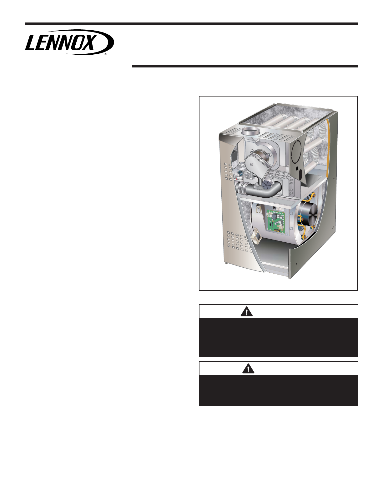
ICOMFORT®-ENABLED SL280UHNV SERIES UNITS
SL280UHNVseries units are 80% effi ciency gas furnac-
es used for upfl ow or horizontal applications only, man-
ufactured with Lennox Duralok heat exchangers formed
of aluminized steel. SL280UHNV units are available in
heating capacities of 40,000 to 100,000 Btuh and cooling
applications up to 5 tons. Refer to Engineering Handbook
for proper sizing.
Units are approved for installations up 4500 ft and factory equipped for use with natural gas only. SL280UHNV
model units are equipped with the iComfort® enabled
SureLight® two-stage variable speed integrated control.
SL280UHNV unit meets the California Nitrogen Oxides
(NOx) Standards and California Seasonal Effi ciency re-
quirements. All units use a redundant gas valve to assure
safety shut-off as required by C.S.A.
All specifi cations in this manual are subject to change.
Procedures outlined in this manual are presented as a
recommendation only and do not supersede or replace local or state codes. In the absence of local or state codes,
the guidelines and procedures outlined in this manual (except where noted) are recommendations only and do not
constitute code.
SL280UHNV
Contents
I-Unit Components..........................................................4
Blower Data ..................................................................16
II-Placement and Installation ........................................ 31
III-Start-Up .................................................................... 31
IV-Heating System Service Checks ..............................32
V-Typical Operating Characteristics .............................34
VI-Maintenance ............................................................35
VII- Wiring and Sequence of Operation ........................38
VIII- Field Wiring With Conventional Thermostat ..........42
IX- Program Unit Capacity Size Modes ........................46
X- Troubleshooting ....................................................... 47
Page 1
WARNING
Improper installation, adjustment, alteration, service
or maintenance can cause property damage, personal
injury or loss of life. Installation and service must be
performed by a licensed professional HVAC installer or
equivalent, service agency, or the gas supplier.
CAUTION
As with any mechanical equipment, contact with sharp
sheet metal edges can result in personal injury. Take
care while handling this equipment and wear gloves and
protective clothing.
©2017 Lennox Industries, Inc.
Page 2
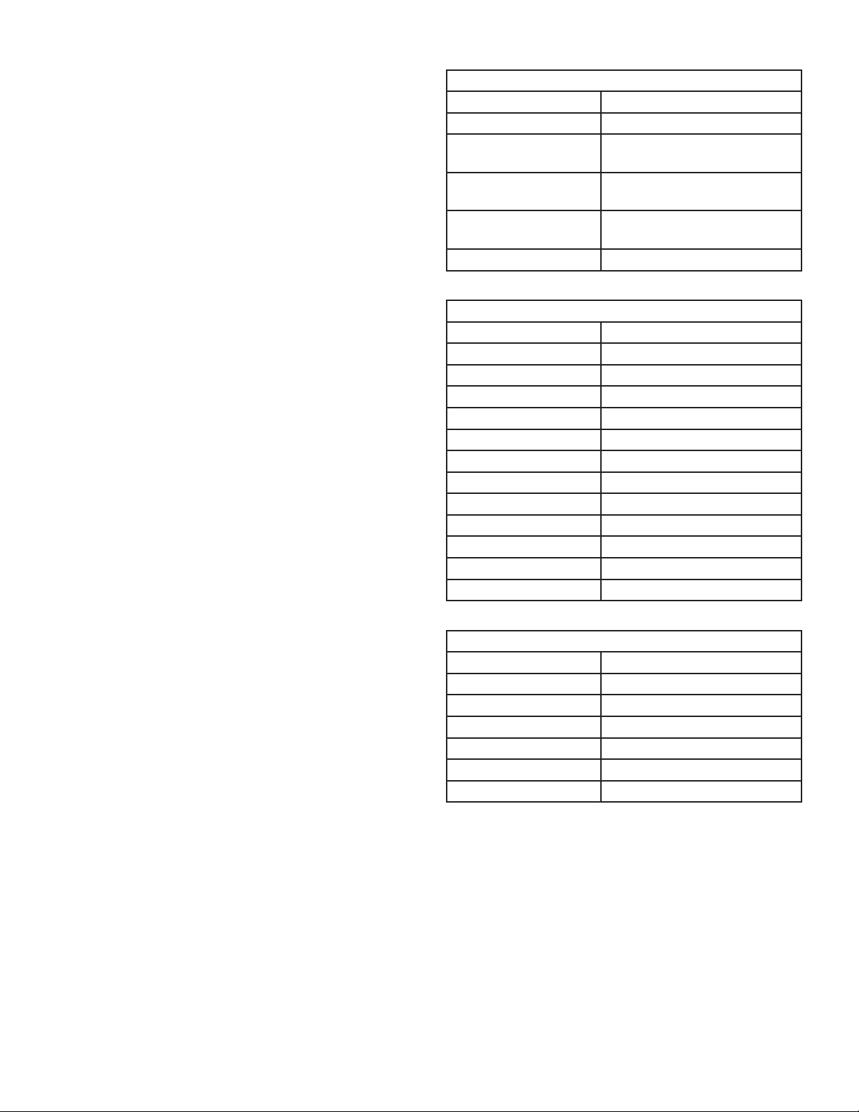
SPECIFICATIONS
Gas
Heating
Performance
High
Fire
Temperature rise range - °F 30 - 60 30 - 60
Gas Manifold Pressure (in. w.g.)
Low
Fire
Temperature rise range - °F 20 - 50 20 - 50
Gas Manifold Pressure (in. w.g.)
High static - in. w.g. Heating 0.8 0.8
Connections
Flue connection − in. round 4 4
in.
Indoor
Wheel nominal diameter x width - in. 10 X 8 11-1/2 X 9
Blower
Tons of add-on cooling 2 - 3 2.5 - 4
Air Volume Range - cfm 606 - 1345 679 - 2002
Electrical Data Voltage 120 volts - 60 hertz - 1 phase
Blower motor full load amps 7.7 12.8
Maximum overcurrent protection 15 20
Shipping Data lbs. - 1 package 112 138
NOTE - Filters and provisions for mounting are not furnished and must be fi eld provided.
1
Annual Fuel Utilization Effi ciency based on DOE test procedures and according to FTC labeling regulations. Isolated combustion system rating for non-weatherized
furnaces.
Model No. SL280UH060NV36A SL280UH080NV48B
1
AFUE 80% 80%
Input - Btuh 60,000 80,000
Output - Btuh 48,000 64,000
3.4 3.4
Natural Gas Only
Input - Btuh 39,000 52,000
Output - Btuh 31,000 41,000
1.5 1.5
Natural Gas Only
Cooling 1.0 1.0
Gas pipe size IPS 1/2 1/2
Motor output - hp 1/2 1.0
SPECIFICATIONS
Gas
Heating
Performance
High
Fire
Temperature rise range - °F 30 - 60 30 - 60
Gas Manifold Pressure (in. w.g.)
Low
Fire
Temperature rise range - °F 20 - 50 25 - 50
Gas Manifold Pressure (in. w.g.)
High static - in. w.g. Heating 0.8 0.8
Connections
Flue connection − in. round 4 4
in.
Indoor
Wheel nominal diameter x width - in. 11-1/2 X 10 11-1/2 X 10
Blower
Tons of add-on cooling 3 - 5 3 - 5
Air Volume Range - cfm 826 - 2305 812 - 2125
Electrical Data Voltage 120 volts - 60 hertz - 1 phase
Blower motor full load amps 12.8 12.8
Maximum overcurrent protection 20 20
Shipping Data lbs. - 1 package 157 161
NOTE - Filters and provisions for mounting are not furnished and must be fi eld provided.
1
Annual Fuel Utilization Effi ciency based on DOE test procedures and according to FTC labeling regulations. Isolated combustion system rating for non-weatherized
furnaces.
Model No. SL280UH080NV60C SL280UH100NV60C
1
AFUE 80% 80%
Input - Btuh 80,000 100,000
Output - Btuh 64,000 80,000
3.4 3.4
Natural Gas Only
Input - Btuh 52,000 65,000
Output - Btuh 41,000 52,000
1.5 1.5
Natural Gas Only
Cooling 1.0 1.0
Gas pipe size IPS 1/2 1/2
Motor output - hp 1.0 1.0
Page 2
Page 3
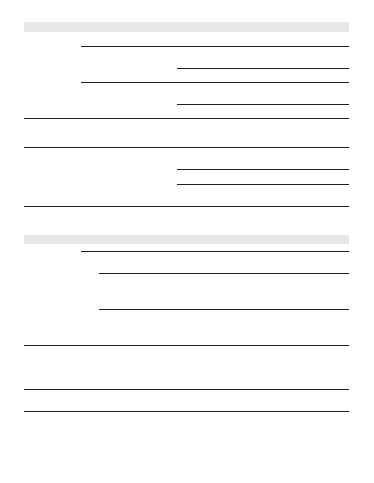
Combustion Air Inducer
A
Gas Valve
Air Intake Pipe
Heat Exchanger
ccess Panel
Inner Access
Panel
(includes two-stage integrated control,
transformer and circuit breaker)
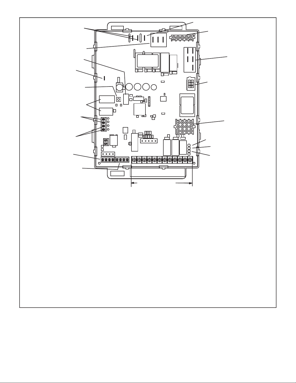
FIGURE 1
Control Box
Blower Assembly
Page 3
Page 4
I-Unit Components
SL280UHNV unit components are shown in Figure 1. The
gas valve, combustion air inducer and burners can be accessed by removing the access panel. Electrical components are in the control box (Figure 2) found in the blower
section.
SL280UHNV units are factory equipped with a bottom return air panel in place. The panel is designed to be fi eld
removed as required for bottom air return. Markings are
provided for side return air and may be cut out in the fi eld.
ELECTROSTATIC DISCHARGE (ESD)
Precautions and Procedures
CAUTION
Electrostatic discharge can affect electronic components.
Take precautions during furnace installation and service
to protect the furnace’s electronic controls. Precautions
will help to avoid control exposure to electrostatic
discharge by putting the furnace, the control and the
technician at the same electrostatic potential. Neutralize
electrostatic charge by touching hand and all tools on an
unpainted unit surface, such as the gas valve or blower
deck, before performing any service procedure.
A- Control Box
1. Control Transformer (T1)
A transformer located in the control box provides power tothe low voltage section of the unit. Transformers on
allmodels are rated 40VA with a 120V primary and a 24V
secondary.
2. Door Interlock Switch (S51)
A door interlock switch rated 14A at 125VAC is wired in series with line voltage. When the inner blower access panel
is removed the unit will shut down.
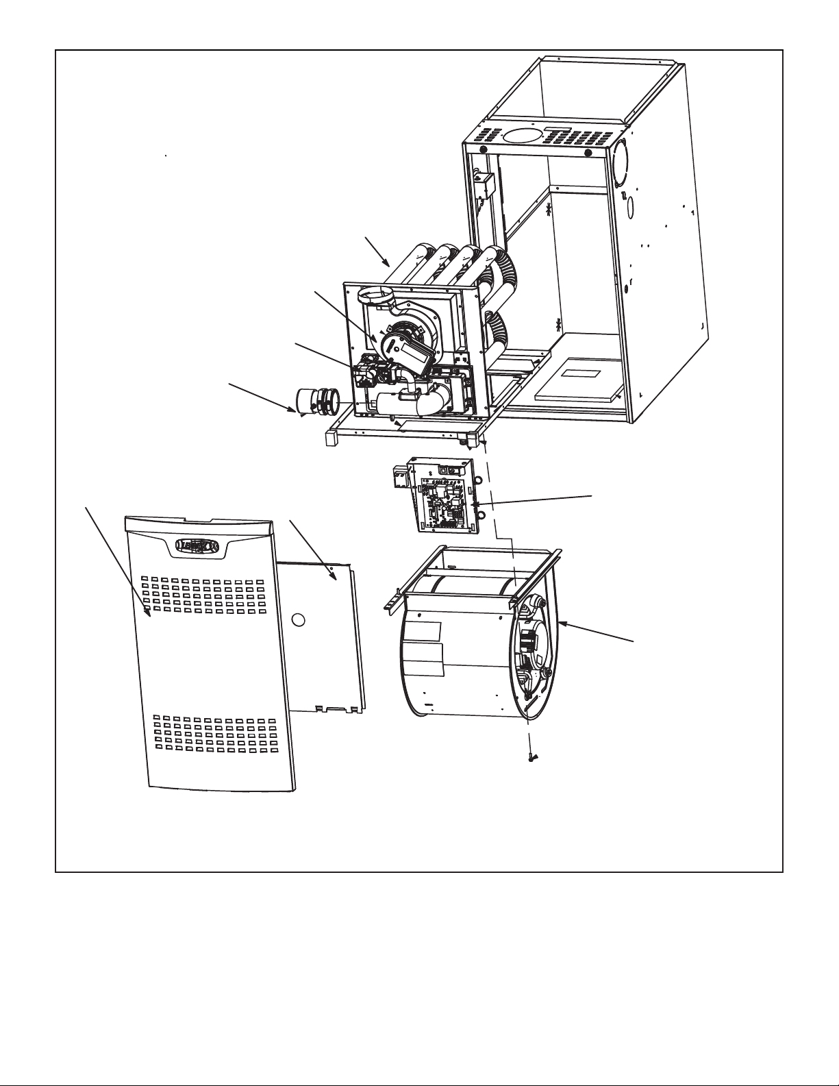
CONTROL BOX
Transformer
Circuit Breaker
Interlock Switch
®
SureLight
FIGURE 2
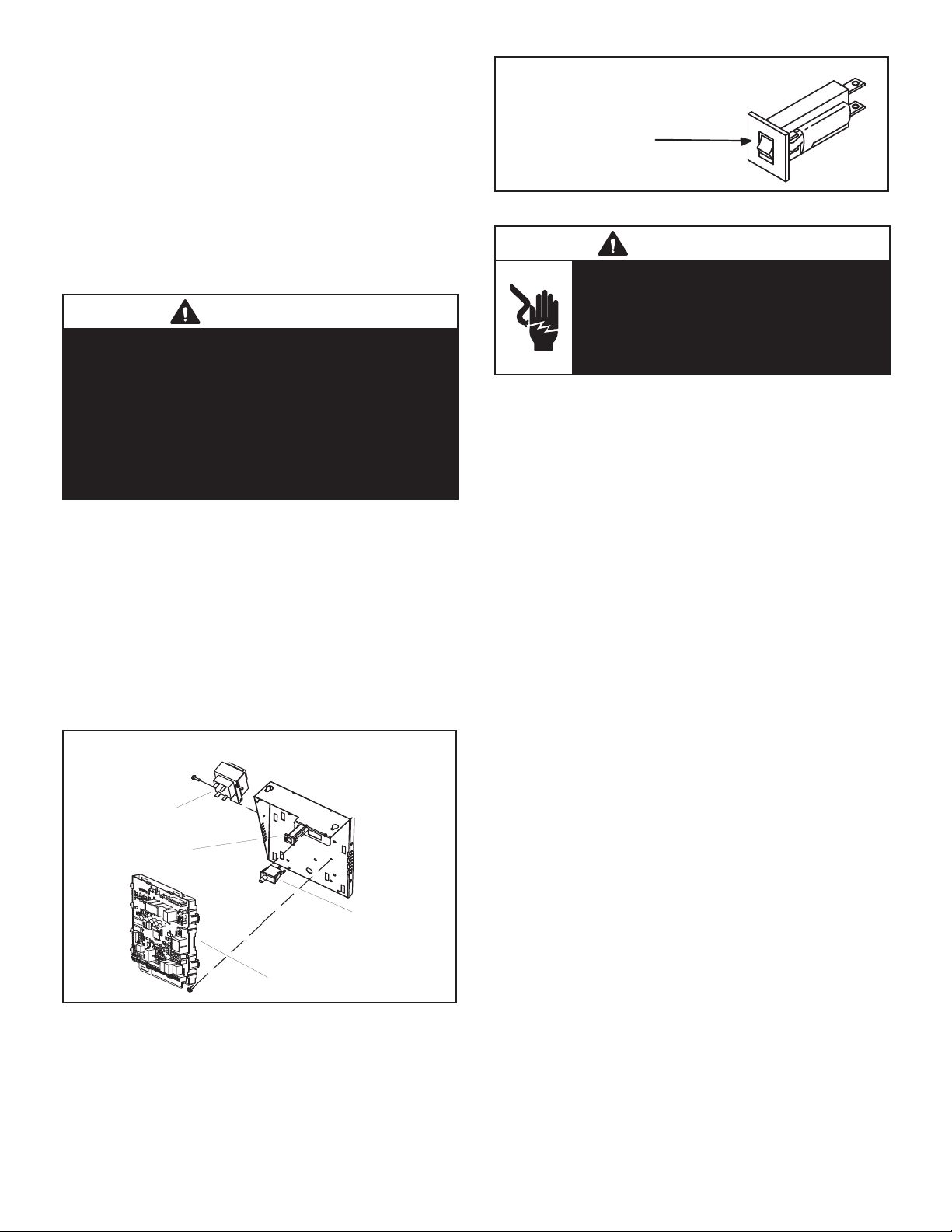
3. Circuit Breaker (CB8)
A 24V circuit breaker is also located in the control box.
The switch provides overcurrent protection to the transformer (T1). The breaker is rated 3A at 32V. If the current
exceeds this limit the breaker will trip and all unit operation will shutdown. The breaker can be manually reset by
pressing the button on the face. See Figure 3
Integrated Control
CIRCUIT BREAKER CB8
PRESS TO RESET
FIGURE 3
WARNING
Shock hazard. Disconnect power before
servicing. Integrated control is not fi eld
repairable. If control is inoperable, simply
replace entire control. Can cause injury or
death. Unsafe operation will resul if repair
is attempted.
4. Integrated Control (A92)
Units are equipped with the icomfort enabled SureLight
® two-stage, variable speed integrated control. This control is used with the icomfort Wi-Fi® thermostat as part
of a communicating comfort system. The control can also
operate with a non-communicating conventional single or
two-stage thermostat. The system consists of a ignition
/ blower control (Figure 4 and Figure 5) with control pin
designations in Table 1, Table 2 and Table 3 and ignitor
(Figure 13). The control and ignitor work in combination
to ensure furnace ignition and ignitor durability. The control provides gas ignition, safety checks and indoor blower
control with two-stage gas heating.
The furnace combustion air inducer, gas valve and indoor
blower are controlled in response to various system inputs
such as thermostat signal, pressure and limit switch signal
and fl ame signal. The control features a seven-segment
LED display, indicating furnace status (including indoor
blower) and error codes. The LED fl ashes in single dig-
its. For example using Table 5 under LIMIT CODE, an “E”
followed by “2” followed by “5” followed by “0”, the limit
switch circuit is open. The control also has two unpowered
(dry) 1/4” contacts for a humidifi er and a 120 volt accesso-
ry terminal. Both rated at (1) one amp each.
Electronic Ignition
At the beginning of the heat cycle the integrated control
monitors the fi rst stage and second stage combustion air
inducer prove switch. The control will not begin the heating
cycle if the fi rst stage prove switch is closed (by-passed).
Likewise the integrated control will not begin the second
stage heating cycle if the second stage prove switch is
closed, and will remain in fi rst stage heat. However, if the
second stage prove switch closes during the fi rst stage
heat pre-purge, the control will allow second stage heat.
Once the fi rst stage prove switch is determined to be open,
the combustion air inducer is energized on low (fi rst stage)
heat speed. When the differential in the prove switch is
great enough, the prove switch closes and a 15-second
pre-purge begins.
Page 4
Page 5
NOTE - During abnormal conditions such as low supply
voltage or low outdoor temperatures and the low fi re pres-
sure switch does not close, the combustion air inducer will
switch to high fi re. After a 15 second pre-purge the high
fi re pressure switch will close and the unit will begin operation on high fi re. After 10 to 20 seconds of high fi re
operation the unit will switch to low fi re.
After the 15-second pre-purge period, the SureLight ignitor warms up for 20 seconds after which the gas valve
opens for a 4-second trial for ignition. The ignitor energizes during the trial until fl ame is sensed. If ignition is
not proved during the 4-second period, the control will try
four more times with an inter purge and warm-up time between trials of 35 seconds. After a total of fi ve trials for
ignition (including the initial trial), the control goes into
Watchguard-Flame Failure mode. After a 60-minute reset
period, the control will begin the ignition sequence again.
Two Stage Operation / Thermostat Selection DIP
Switch
The control can be utilized in two modes: SINGLE-STAGE
thermostat or TWO-STAGE thermostat. The thermostat
selection is made using a DIP switch and must be positioned for the particular application. DIP switch 1, labeled
T”STAT HEAT STAGE is factory-set in the OFF position for
use with a two-stage thermostat. Move the DIP switch to
ON for use with a single stage thermostat.
While in the single-stage thermostat mode, the burners
will always fi re on fi rst-stage heat. The combustion air in-
ducer will operate on low speed and indoor blower will
operate on low heat speed. The unit will switch to second
stage heat after a “recognition period”. DIP switch 2, labeled SECOND STAGE DELAY, is factory set in the OFF
position for a 7 minute recognition period. The switch can
be moved to the ON position for a 12 minute recognition
period, after which time the unit will switch to secondstage
heat.
While in the two-stage thermostat mode (two DIP switch
setting) the burners will fi re on fi rst-stage heat. The com-
bustion air inducer will operate on low speed and indoor
blower will operate on low heat speed. The unit will switch
to second-stage heat on call from the indoor thermostat.
If there is a simultaneous call for fi rst and second stage
heat, the unit will fi re an fi rst stage heat and switch to sec-
ond stage heat after 30 seconds of operation. See Sequence of Operation fl ow charts in the back of this manual
for more detail.
TABLE 1
SureLight® Control 5 Pin Terminal Designation
PIN# Function
1 Ignitor
2 Combustion Air Inducer High
Speed
3 Combustion Air Inducer Low
Speed
4 Combustuion Air Inducer
Neutral
5 Ignitor Neutral
TABLE 2
SureLight® Control 12 Pin Terminal Designation
PIN# Function
1 Gas Valve High Fire
2 Second Stage Prove Switch
3 Rollout In
4 Ground
5 24V Hot
6 Primary Limit In
7 Gas Valve Low Stage
8 Gas Valve Common
9 24V Neutral
10 Ground
11 Rollout Switch Out
12 1st Stage Prove Switch
TABLE 3
SureLight® Control 6 Pin Terminal Designation
PIN# Function
1 Data Input From Motor
2 Common
3 Not Used
4 Data Output To Motor
5 5 Volt Bias Supply
6
Not Used
Page 5
Page 6
HUM
LINE 1
7 SEGMENT LED
FLAME SENSE
DIAGNOSTIC
PUSH BUTTON
DIP SWITCHES
ACC
HS/ CAI
INDOOR
BLOWER
CONNECTOR
NEUTRAL
OUTDOOR AIR
SENSOR
TERMINALS
DISCHARGE AIR
SENSOR
TERMINALS
TB83
COMMUNICATING
OUTDOOR
EQUIPMENT
I + I -CRI + I -
TB84
COMMUNICATING
INDOOR
THERMOSTAT
R
RS-BUS LINK (TB82, future use)
I+ = DATA HIGH CONNECTION
I - = DATA LOW CONNECTION
RS-BUS OUTDOOR (TB83)
R = 24VAC
I + = DATA HIGH CONNECTION
I - = DATA LOW CONNECTION
C = 24VAXC COMMON
RS-BUS INDOOR (TB84)
R = 24VAC
I + = DATA HIGH CONNECTION
I - = DATA LOW CONNECTION
C = 24VAXC COMMON
1/4” QUICK CONNECT TERMINALS
HUM = UNPOWERED NORMALLY OPEN (DRY) CONTACTS
XMFR = 120 VAC OUTPUT TO TRANSFORMER
LI = 120 VAC INPUT TO CONTROL
ACC = 120 VAC OUTPUT TO OPTIONAL ACCESSORY
NEUTRALS = 120 VAC NEUTRAL
C
W1 W2 GY2Y1
NON-COMMUNICATINGNG
24V TERMINALS
12 PIN LOW
VOLTAGE
CONNECTOR
W915 Y1 TO Y2
2 STAGE COMPR
W951 R TO O
HEAT PUMP
W914 R TO DS
DEHUM OR
CC
RDHLODS
HARMONY
THERMOSTAT CONNECTIONS (TB1)
DS = DEHUMIDIFICATION SIGNAL
W2 = HEAT DEMAND FROM 2ND STAGE T/STAT
W1 = HEAT DEMAND FROM 1ST STAGE T/STAT
R = CLASS 2 VOLTAGE TO THERMOSTAT
G = MANUAL FAN FROM T'STAT
C = THERMOSTAT SIGNAL GROUND CONNECTED TO
TRANSFORMER GRD (TR) & CHASIS GROUND (GRD)
Y1 = THERMOSTAT 1ST STAGE COOL SIGNAL
Y2 = THERMOSTAT 2ND STAGE COOL SIGNAL
O = THERMOSTAT SIGNAL TO HEAT PUMP
DH = DEHUMIDIFICATION OUTPUT COMMUNICATING
L = USE ONLY WITH A COMMUNICATING THERMOSTAT
AND A NON-COMMUNICATING OUTDOOR UNIT
REVERSING VALVE
THERMOSTAT ONLY
FIGURE 4
Page 6
Page 7
THERMOSTAT SELECTION
1
2
*
TWO STAGE
THERMOSTAT
1−STAGE
THERMOSTAT
(TIMED STAGING)
−SEE SW #2
HEATING BLOWER−OFF DELAY
*
90 SECOND
HTG BLOWER
OFF DELAY
60 SECOND
HTG BLOWER
OFF DELAY
120 SECOND
HTG BLOWER
OFF DELAY
180 SECOND
HTG BLOWER
OFF DELAY
−BLOWER ON DELAY − 30 SEC. FIXED
3
ON
1
2
3
ON
1
2
3
ON
1
2
3
ON
1
2
3
ON
1
2
3
ON
HEATING MODE BLOWER SPEED
9
+ 24%
+ 18%
+ 12%
INCREASE AIR HTG CFM
+ 6%
*
FACTORY
DEFAULT
− 6%
− 12%
DECREASE AIR HTG CFM
− 18%
ON
9
ON
9
ON
9
ON
9
ON
9
ON
9
ON
9
ON
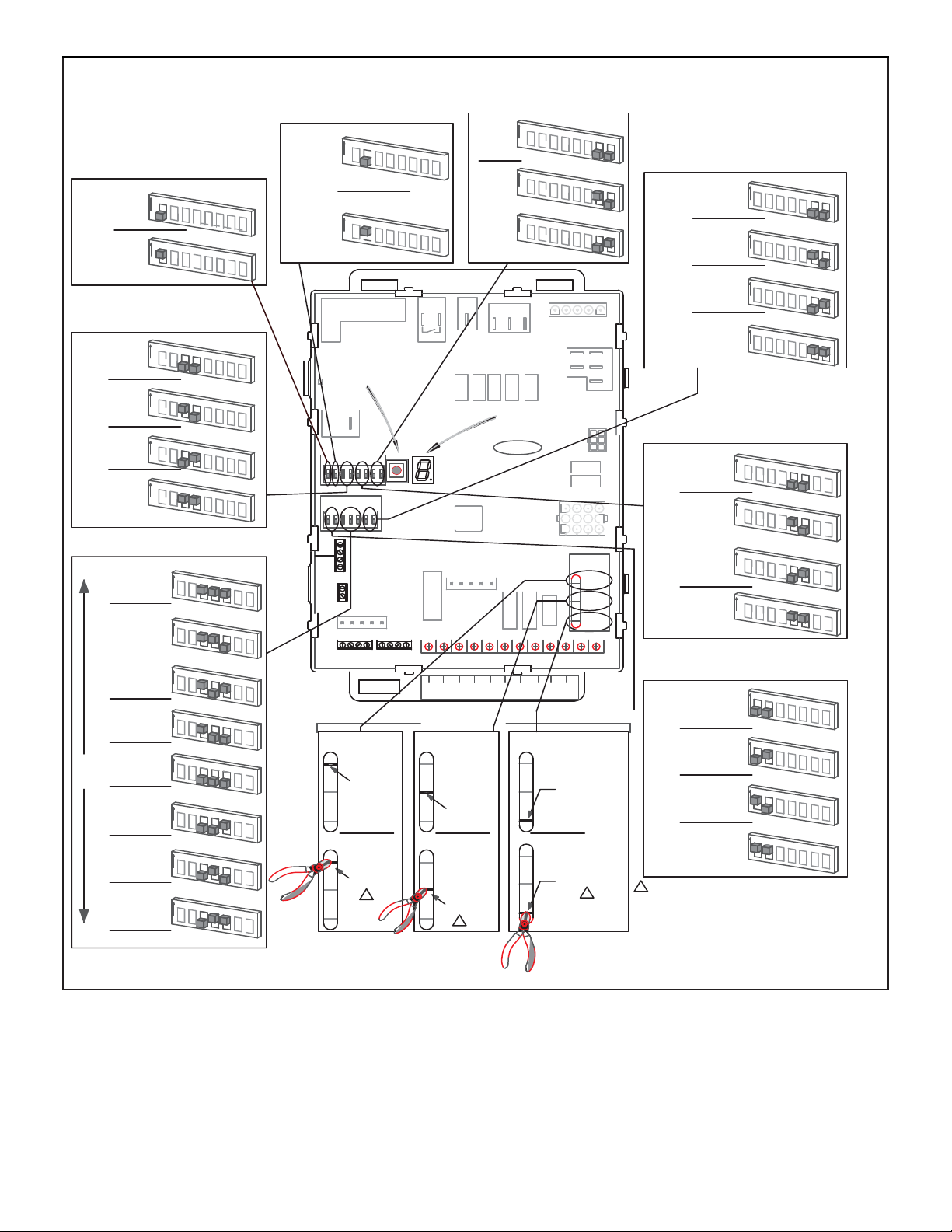
INTEGRATED CONTROL CONFIGURATION GUIDE
2ND STAGE HEAT ON DELAY
1
2
3
4
5
7 MIN
DELAY
12 MIN
DELAY
FLAME
SENSE
123456
ON
S4S3
911
10
ON
OUTDOOR
SENSOR
DISCHARGE
AIR SENSOR
I+ I
ON
1
ON
DIAGNOSTIC
PUSH BUTTON
13
14
12
*
UPSTAGE
4
5
6
7
8
4
5
6
7
8
4
5
6
7
8
4
5
6
7
8
4
5
6
7
8
4
5
6
7
8
11
13
10
15
12
14
UPSTAGE
6
7
2
3
4
5
6
7
HUM
S1
7
8
15
CLG BLOWER SPEED ADJUSTMENT
*
DEFAULT
8
8
ACC
−
11
13
10
12
15
14
R
11
13
10
10
10
10
10
10
15
12
14
11
13
12
15
14
11
13
12
15
14
11
13
15
12
14
11
13
12
15
14
11
13
12
15
14
I+ I−CRI+ I−
OUTDOOR EQUIPMENT
1−STG COMPRESSOR
W915
2 STAGE
COMPR
DO NOT CUT
2−STG COMPRESSOR
W915
2 STAGE
COMPR
CUT LINK
2−STAGE
COMPRESSOR LINK
(JUMPERS Y1 to Y2)
W915
INDOOR EQUIPMENT
1
C
W1W2GY2
W2
W1
ON−BOARD LINK
OPTION SELECTION
A/C UNIT
W951
HEAT
PUMP
DO NOT CUT
HEAT PUMP UNIT
W951
HEAT
PUMP
CUT LINK
HEAT PUMP LINK
(JUMPERS R to O)
W951
G
Y2
1
ON
ON
+ 10%
ON
− 10%
L1
DIAGNOSTIC
LED
SureLight
Y1 C C DH L O DSR
C
C
Y1
1
2
3
4
5
6
7
1
2
3
4
5
6
7
1
2
3
4
5
6
7
HSI/CAI
1
J3
®
R
NO HARMONY ZONING
NO SIGNATURESTAT
W/ DS CONNECTION
5
N
IGN
CAI1
CAI2
P79
14
3
110
4 7
3
12
CUT FOR
OPTION
SELECTION
W915
2 STAGE
COMPR
W951
HEAT
PUMP
W914
DEHUM
HARMONY
L
DH
OR
DO NOT CUT
W914
DEHUM
or
HARMONY
HARMONY ZONING
OR
SIGNATURESTAT W/
DS CONNECTION
CUT LINK
1
W914
DEHUM
or
HARMONY
DEHUMIDIFICATION−
HARMONY LINK
(JUMPERS R to DS)
W914
8
8
8
N
NEUTRALS
6
J2
CONTINUOUS FAN MODE BLOWER SPEED
MEDIUM−LOW
*
SPEED
(38%)
MEDIUM−HIGH
SPEED
(70%)
LOW
SPEED
(28%)
HIGH
SPEED
(100%)
9
11
13
10
12
ON
9
ON
9
ON
9
ON
14
11
10
12
14
11
10
12
14
11
10
12
14
COOLING MODE BLOWER SPEED
1
2
3
4
5
*
HIGH
SPEED
MEDIUM−HIGH
SPEED
MEDIUM−LOW
SPEED
LOW
SPEED
COOLING MODE BLOWER RAMPING
*
OPTION A
OFF−50%−82%−
100%−50%−OFF
OPTION B
OFF−82%−100%−OFF
OPTION C
OFF−100%−100%−OFF
OPTION D
OFF−100%−OFF
−CUT ON−BOARD LINK (SOLDER TRACE) COMPLETELY THROUGH
1
BOTH LAYERS ON THE CONTROL BOARD
−LINKS CUT IN ERROR −INSTALL A JUMPER ON THE APPROPRIATE
TERMINALS ON THE TERMINAL STRIP
−PROTECTIVE PLASTIC FILM ON DIP SWITCHES MAY BE
REMOVED FOR EASE IN SETTING OF DIP SW.
ON
1
ON
1
ON
1
ON
9
ON
9
ON
9
ON
9
ON
* FACTORY DEFAULT
6
7
2
3
4
5
6
7
2
3
4
5
6
7
2
3
4
5
6
7
11
13
10
12
14
11
13
10
12
14
11
13
10
12
14
11
13
10
12
14
15
15
15
15
8
8
8
8
15
15
15
15
FIGURE 5
Page 7
Page 8

TABLE 4
Integrated Control Diagnostic Modes
Dispaly Action (when button released)
No change (idle)* Remain in idle mode
Solid “E” Enter diagnostic recall mode
Solid “D” Discharge Air Installed
Solid “F” Enter fl ame signal mode
Solid “P” (variable speed only) Program unit capacity/size (Unit Code)
Two horizontal bars = Soft disable
* No change implies the display will continue to show whatever is currently being displayed for normal operation (blinking decimal, active error code,
heat state, etc..)
Diagnostic LED (Figure 5)
The seven-segment diagnostic LED displays operating
status, target airfl ow, error codes and other information.
The table beginning on Page 9 lists diagnostic LED codes.
Diagnostic Push Button (Figure 5)
The diagnostic push button is located adjacent to the seven-segment diagnostic LED. This button is used to enable
the Error Code Recall “E” mode and the Flame Signal
“F” mode. Press the button and hold it to cycle through a
menu of options. Every fi ve seconds a new menu item will
be displayed. When the button is released, the displayed
item will be selected. Once all items in the menu have
been displayed, the menu resumes from the beginning
until the button is released.
Error Code Recall Mode
Select ”E” from the menu to access the most recent 10
error codes. Select “c” from the Error Code Recall menu
to clear all error codes. Button must be pressed a second
time while “c” is fl ashing to confi rm command to delete
codes. Press the button until a solid “≡” is displayed to exit
the Error Code Recall mode.
Flame Signal Mode
Select ”F” from the menu to access the fl ame signal mode.
The integrated control will display the fl ame current on 7
segment LED in in micro amps (uA).
• Flame signal mode is exited after any of the following: Power is reset
• Pressing and holding push button until 3 horizontal
lines “≡” are displayed
• 10 minutes after entering the fl ame sense mode.
Program Unit Capacity/Size Mode
After the “P” is selected (by releasing the push button)
the integrated control will start fl ashing the “P” on display
for 90 seconds. If push button is pressed again and held
during that time, the control will start to display characters
corresponding to different variable speed furnace models
for 3 seconds each. While the wanted character-model is
displayed push button has to be released. Selected option
will fl ash display for 10 seconds and during that time push
button has to be pressed and held for 5 seconds. Once
control accepts new setting it will store data in non-volatile
memory and reset itself. If 10 seconds expires or push
button is held less than 5 seconds, control will exit fi eld
test mode and go into idle without changing programming
the unit size.
Soft Disable
Soft disabling is when thermostat fi nds a device on the
BUS that it does not recognize and the thermostat sends
a the device a message to be in soft disabling mode until
properly confi gured. Two horizontal bars will display.
Steps to follow if the damper control module is displaying
the soft disable code.
1 - Confi rm proper wiring between all devices
(thermostat, damper control module, indoor and
outdoor).
2 - Cycle power to the control that is displaying the soft
disable code.
3 - Put the room thermostat through set up.
4 - Go to setup / system devices / thermostat / edit
/ then push reset.
5 - Go to setup / system devices / thermostat / edit /
then push resetAll.
Page 8
Page 9
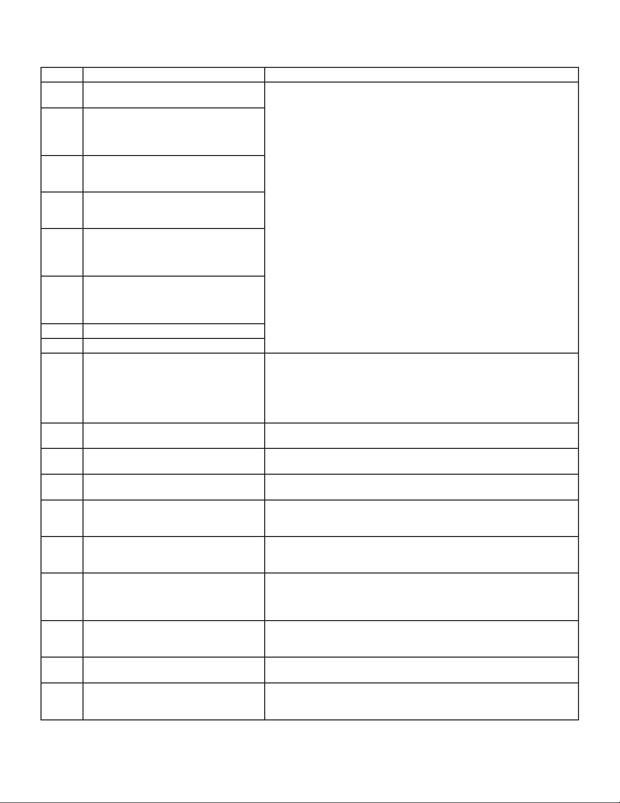
TABLE 5
Integrated Diagnostic Codes/Status of Equipment
Code Diagnostic Codes/Status of Equipment Action Required to Clear and Recover
. Idle mode (Decimal blinks at 1 Hertz -- 0.5
second ON, 0.5 second OFF).
A Cubic feet per minute (cfm) setting for
indoor blower (1 second ON, 0.5 second
OFF) / cfm setting for current mode
displayed.
C Cooling stage (1 second ON, 0.5 second
OFF) / 1 or 2 displayed / Pause / cfm
setting displayed / Pause / Repeat codes).
d Dehumidifi cation mode (1 second ON) /
1 second OFF) / cfm setting displayed /
Pause / Repeat Codes).
h Heat pump stage (1 second ON, 0.5
second OFF) / % of input rate displayed
/ Pause / cfm setting / Pause / Repeat
codes.
H Gas Heat Stage (1 second ON, 0.5 second
OFF) / 1 or 2 displayed / Pause / cfm
setting displayed / Pause / Repeat codes.
Blinking during ignition.
dF Defrost mode.
U Discharge Air Temperature
E105 Device communication problem - No other
devices on RS BUS (Communication
system).
E110 Low line voltage. Line Voltage Low (Voltage lower than nameplate rating). Check power line
E111 Low line voltage. Reverse line power voltage wiring. System resumes normal operation 5
E112 Ground not detected System shuts down. Provide proper earth ground. System resumes normal
E113 High line voltage. Line Voltage High (Voltage higher than nameplate rating). Provide power
E114 Line voltage frequency out-of-range. No 60 Hertz Power. Check voltage and line power frequency. Correct
E115 Low 24V - Control will restart if the error
recovers.
E116 High 24V. 24 Volt Power High (Range is 18 to 30 volts). Check and correct voltage.
E117 Poor ground detected (Warning only) Provide proper grounding for unit. Check for proper earth ground to the
E120 Unresponsive device. Communication
only.
Equipment is unable to communicate. Indicates numerous message
errors. In most cases errors are related to electrical noise. Make sure
high voltage power is separated from RSBus. Check for miswired and/or
loose connections between the stat, indoor unit and outdoor unit. Check
for a high voltage source of noise close to the system. Fault clears after
communication is restored.
voltage and correct. Alarm clears 5 seconds after fault recovered.
seconds after fault recovered.
operation 5 seconds after fault recovered.
voltage within proper range. System resumes normal operation 5 seconds
after fault recovered.
voltage and frequency problems. System resumes normal operation 5
seconds after fault recovered.
24-Volt Power Low (Range is 18 to 30 volts). Check and correct voltage.
Check for additional power-robbing equipment connected to system. May
require installation of larger VA transformer to be installed in furnace / air
handler. Clears after fault recovered.
Check for proper line voltage (120V, 240V, etc.) to equipment. Clears when
control senses proper voltage.
system. Warning only will clear 30 seconds after fault recovered.
Usually caused by delay in outdoor unit responding to indoor unit poling.
Recycle power. Check all wiring connections. Cleared after unresponsive
device responds to any inquiry.
Page 9
Page 10
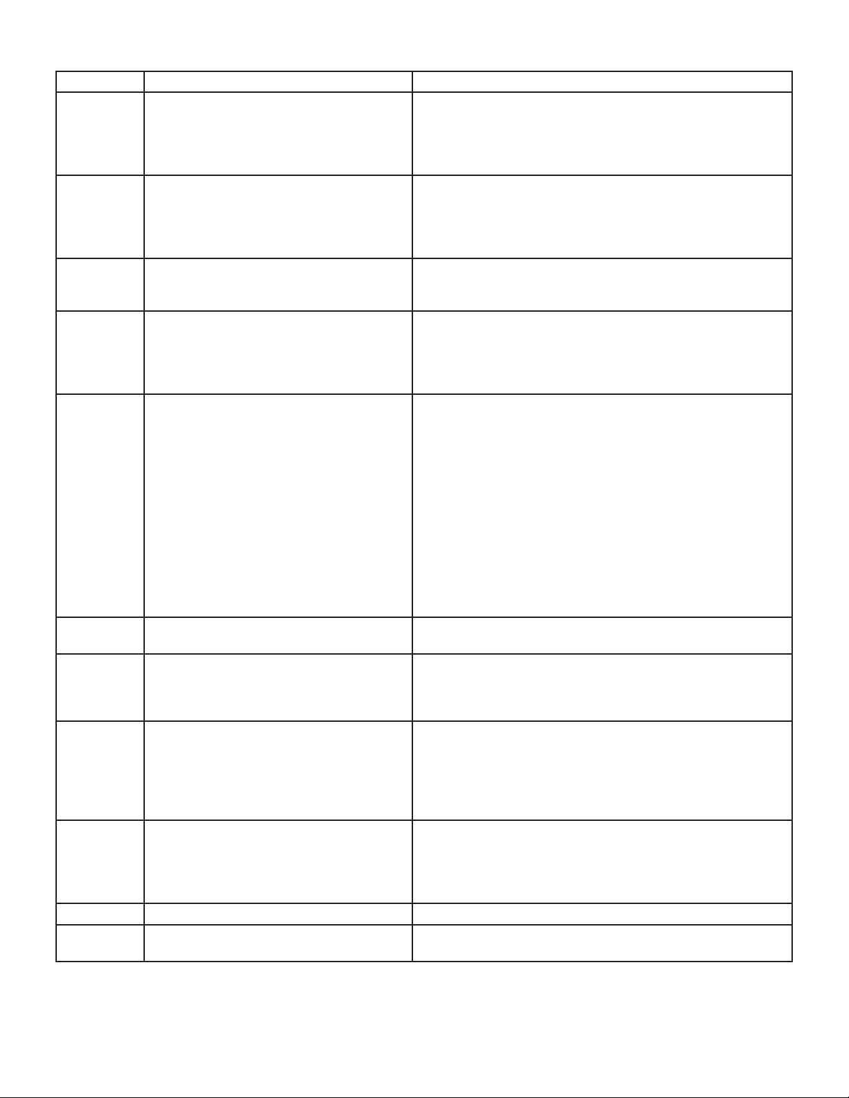
TABLE 5 Continued
Code
E124 Active communicating thermostat signal
Diagnostic Codes/Status of Equipment Action Required to Clear and Recover
Equipment lost communication with the thermostat. Check
missing for more than 3 minutes.
four wiring connections, ohm wires and cycle power at the
thermostat. Alert stops all services and waits for heartbeat
message from thermostat (subnet controller). Cleared after
valid thermostat (subnet controller) message is received.
E125 Control failed self-check, internal error,
failed hardware. Will restart if error recovers. Integrated control not communicating.
Hardware problem on the control. Cycle power on control.
Replace if problem prevents service and is persistent. Criti-
cal alert. Cleared 300 seconds after fault recovered.
Covers hardware errors (fl ame sense cir-
cuit faults, pin shorts, etc.).
E126 Control internal communication problem. Hardware problem on the control. Cycle power on con-
trol. Replace if problem prevents service and is persistent.
Cleared 300 seconds after fault recovered.
E131 Corrupted control parameters (Verify con-
fi guration of system). Communicating only.
Reconfi gure the system. Replace control if heating or cool-
ing is not available. Only applicable in the communicating
mode, not in startup. Exit from Commissioning and Execute
‘Set Factory Default mode Control will still operate on default
parameter settings
E180 Outdoor air temperature sensor failure.
Only shown if shorted or out-ofrange.
Compare outdoor sensor resistance to temperature/ resis-
tance charts in unit installation instructions. Replace sensor
pack if necessary. At beginning of (any) confi guration, furnace
or air handler control will sense outdoor air and discharge
air temperature sensor(s). If detected (reading in range),
appropriate feature will be set as ‘installed’ and that could
be seen in ‘About’ screen. In normal operation after control
recognizes sensors, alarm will be sent if valid temperature
reading is lost. To get rid of setting and alarm, redo confi gu-
ration and make sure that temperature sensor is marked as
‘not installed’ in Indoor Unit ‘About’ screen. When Indoor unit
control is replaced, thermostat will ‘tell’ new control if tem-
perature sensor is in system or not. Clears 30 seconds after
fault recovered.
E200 Hard lockout - Rollout circuit open or pre-
viously open.
E201 Indoor blower communication failure - Un-
able to communicate with blower motor.
Correct cause of rollout trip, or replace fl ame rollout switch.
Test furnace operation. Cleared after fault recovered.
Indoor blower communication failure (including power out-
age). Lost communication with indoor blower motor. Possible
causes: motor not powered, loose wiring. Problem may be
on control or motor side. Cleared after fault recovered.
E202 Indoor blower motor mis-match - Indoor
motor horsepower does not match unit capacity.
Incorrect appliance capacity code selected. Check for proper
confi guring under: Unit Size Codes for Furnace/Air Handler
on confi guration guide or in installation instructions. Cleared
after the correct match is detected following a reset. (Re-
move thermostat from system while applying power and re-
programming.)
E203 Appliance capacity / size is NOT pro-
grammed. Invalid unit codes refer to confi guration fl ow chart.
No appliance capacity code selected. Check for proper con-
fi guring under: Unit Size Codes for Furnace on confi guration
guide or in installation instructions. Critical Alert. Cleared af-
ter valid unit code is read following a reset. (Remove thermo-
stat from system while applying power and reprogramming.)
E204 Gas valve mis-wired. Check gas valve operation and wiring. Clears when repaired.
E205 Gas valve control relay contact shorted. Check wiring on control and gas valve. If wiring is correct,
replace control.
Page 10
Page 11
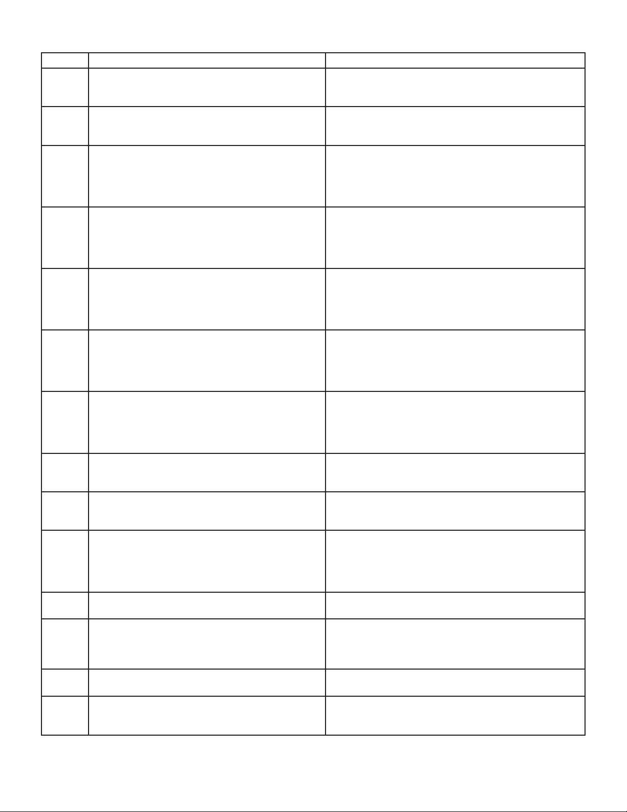
TABLE 5 Continued
Code Diagnostic Codes/Status of Equipment Action Required to Clear and Recover
E206 Gas valve second-stage relay failure Furnace will operate on 1st stage for remainder of the
heating demand. Will clear after fault recovered. If unable to operate 2nd stage, replace control.
E207 Hot surface ignitor sensed open. Measure resistance of hot surface ignitor. Replace if
open or not within specifi ed range found in IOM. Re-
sumes normal operation after fault is cleared.
E223 Low pressure switch failed open. Check pressure (inches w.c.) of low pressure switch
closing on heat call. Measure operating pressure (inches w.c.). Inspect vent and combustion air inducer for
correct operation and restriction. Resumes normal operation after fault is cleared
E224 Low pressure switch failed closed. Check operation of low pressure switch to see if it is
stuck closed on heat call longer than 150 seconds. Measure operating pressure (inches w.c.). Inspect vent and
combustion air inducer for correct operation and restriction. Resumes normal operation after fault is cleared.
E225 High pressure switch failed open. Check pressure (inches w.c.) of high pressure switch
closing on heat call. Measure operating pressure (inches w.c.). Inspect vent and combustion air inducer for
correct operation and restriction. Resumes normal operation after fault is cleared.
E226 High pressure switch failed closed Check operation of high pressure switch closing on heat
call. Measure operating pressure (inches w.c.). Inspect
vent and combustion air inducer for correct operation
and restriction. Resumes normal operation after fault is
cleared.
E227 Low pressure switch open during trial for ignition
or run mode.
E228 Combustion air inducer calibration failure Unable to perform pressure switch calibration. Check
E229 Ignition on high fi re IFC switched to high fi re ignition because low fi re pres-
E240 Low fl ame current - Run mode. Check micro-amperes of fl ame sensor using control
E241 Flame sensed out of sequence - Flame still pres-
ent.
E250 Limit switch circuit open. Check for proper fi ring rate on furnace. Ensure there is
E252 Discharge air temperature too high (gas heat only). Check temperature rise, air fl ow and input rate. Cleared
E270 Soft lockout - Exceeded maximum number of re-
tries. No fl ame current sensed.
Check pressure (inches w.c.) of low pressure switch
closing on heat call. Measure operating pressure (inches w.c.). Inspect vent and combustion air inducer for
correct operation and restriction. Resumes normal operation after fault is cleared.
vent system and pressure switch wiring connections.
Resumes normal operation after fault is cleared.
sure switch did not close in allowed time. No action is
needed.
diagnostics or fi eld-installed mode. Clean or replace
sensor. Measure voltage of neutral to ground to ensure
good unit ground. Alert clears after current heat call has
been completed.
Shut off gas. Check for gas valve leak. Replace, if necessary. Alert clears when fault is recovered.
no blockage in heater. Check for proper air fl ow. If limit
not closed within 3 minutes, unit will go into 1-hour soft
lockout. Resumes normal operation after fault is cleared.
when heat call is fi nished.
Check for proper gas fl ow. Ensure that ignitor is lighting
burner. Check fl ame sensor current. Clears when heat
call fi nishes successfully.
Page 11
Page 12
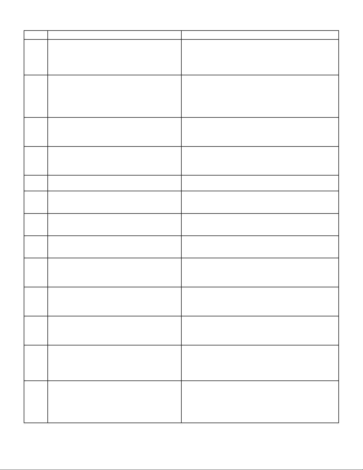
TABLE 5 Continued
Code Diagnostic Codes/Status of Equipment Action Required to Clear and Recover
E271 Soft lockout - Exceeded maximum number of re-
tries. Last retry failed due to the pressure switch
opening.
E272 Soft lockout - Exceeded maximum number of re-
cycles. Last recycle due to the pressure switch
opening.
E273 Soft lockout - Exceeded maximum number of re-
cycles. Last recycle due to fl ame failure.
E274 Soft lockout - Exceeded maximum number of re-
cycles. Last recycle failed due to the limit circuit
opening or limit remained open longer than 3 minutes
E275 Soft lockout - Flame sensed out of sequence.
Flame signal is gone.
E276 Watchguard calibration failure. Unable to perform pressure switch calibration. Check vent
E290 Ignitor circuit fault - Failed ignitor or triggering cir-
cuitry.
E291 Heat air fl ow restricted below the minimum. Check for dirty fi lter and air fl ow restriction. Check blower
E292 Indoor blower motor unable to start due to ob-
structed wheel, seized
bearings.
E294 Combustion air inducer over current. Check combustion blower bearings, wiring and amps. Re-
E295 Indoor blower motor temperature is too high. Indoor blower motor over temperature (motor tripped on
E310 Discharge error temperature sensor failure. Only
shown if shorted or
out of range.
E311 Heat rate reduced to match indoor blower air fl ow. Warning Only. Furnace blower in cutback mode due to
Check pressure (inches w.c.) of low pressure switch closing on heat call. Measure operating pressure (inches w.c.).
Inspect vent and combustion air inducer for correct operation and restriction. Clears when heat call fi nishes suc-
cessfully.
Check operation of low pressure switch to see if it is stuck
closed on heat call. Check pressure (inches w.c.) of high
pressure switch closing on heat call. Measure operating
pressure (inches w.c.). Inspect vent and combustion air
inducer for correct operation and restriction. Clears when
heat call fi nishes successfully.
Check micro-amperes of fl ame sensor using control diag-
nostics or fi eld-installed mode. Clean or replace sensor.
Measure voltage of neutral to ground to ensure good unit
ground. Clears when heat call fi nishes successfully.
Shut down system. 1-hour soft lockout. Check fi ring rate
and air fl ow. Check for blockage. Clears when heat call
fi nishes successfully.
Shut off gas. Check for gas valve leak. 1-hour soft lockout.
Clears when fl ame has been proven stable.
system and pressure switch wiring connections. 1-hour soft
lockout. Clears when calibration has fi nished successfully.
Measure resistance of hot surface ignitor. Replace if open
or not within specifi cations. 1-hour soft lockout. Clears
when fl ame has been proven stable.
performance. 1-hour soft lockout. Cleared when heat call
fi nishes successfully.
Indoor blower motor unable to start (seized bearing, stuck
wheel, etc.). Replace motor or wheel if assembly does not
operate or meet performance standards. 1-hour soft lockout. Clears after circulator successfully starts.
place if does not operate or does not meet performance
standards. Clears after inducer current is sensed to be inrange after the ignition following the soft lockout or reset.
internal protector). Check motor bearings and amps. Replace if necessary. Cleared after blower demand is satisfi ed.
Compare outdoor sensor resistance to temperature/ resistance charts in installation instructions. Replace sensor
if necessary. Cleared in Communicating mode: 30 seconds after fault recovered. In Non- Communicating mode:
Cleared after the current heat call is completed.
restricted airfl ow. Reduce fi ring rate every 60 seconds to
match available CFM. Check fi lter and duct system. To
clear, replace fi lter if needed or repair/ add duct. 2-stage
controls will reduce fi ring rate to 1st stage. Clears when
heat call fi nishes successfully.
Page 12
Page 13
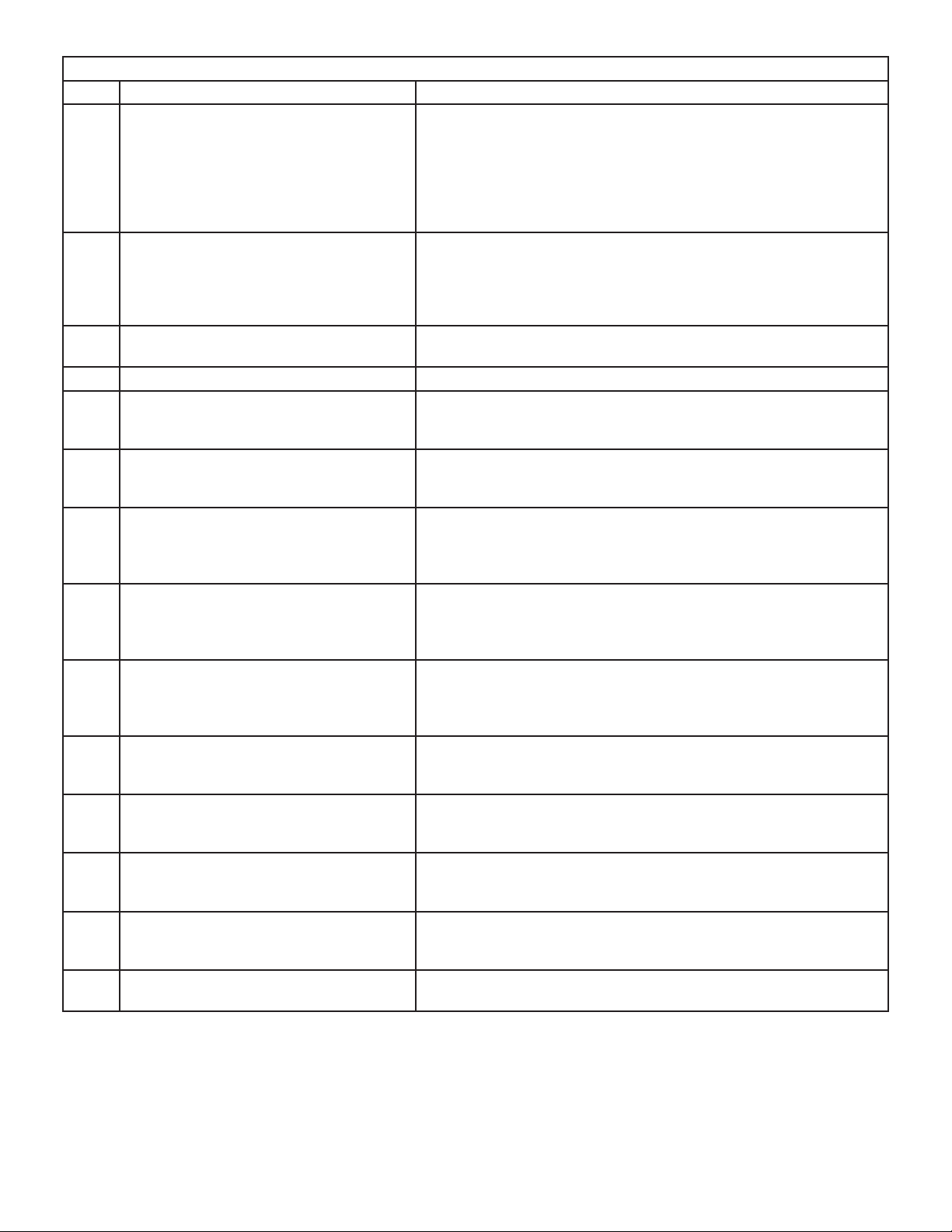
TABLE 5 Continued
Code Diagnostic Codes/Status of Equipment Action Required to Clear and Recover
E312 Restricted air fl ow in cooling or continu-
ous fan mode is lower than cfm setting.
E313 Indoor or outdoor unit capacity mismatch.
Communication only.
E331 Global network connection - Communica-
tion link problem.
E334 Relay “Y1” stuck on interated control. Replace integrated control.
E347 No 24 Volt output on Y1 of ”integrated
control” with non communicating outdoor
unit.
E348 No 24 Volt output on Y2 of ”integrated
control” with non?communicating outdoor
unit.
E349 No 24 Volts between R & O on ”integrated
control” with non communicating outdoor
unit (Dual fuel module required for heat
pump application
E370 Interlock switch sensed open for 2 min-
utes.
E400 LSOM - Compressor internal overload
tripped.
E401 LSOM Compressor long run cycle or low
system pressure.
E402 LSOM - Outdoor unit system pressure
trip.
E403 LSOM - Compressor short-cycling. .(Run-
ning less than 4 minutes). Outdoor unit
pressure trip
E404 LSOM - Compressor rotor locked. Com-
pressor short-cycling. (Running less than
4 minutes).
E405 LSOM - Compressor open circuit. Compressor circuit open (due to power disconnection, open fuse,
Warning Only. Restricted airfl ow - Indoor blower is running at a re-
duced CFM (Cutback Mode - The variable speed motor has pre-set
speed and torque limiters to protect the motor from damage caused
by operating outside of design parameters (0 to 0.8” W.C.. total external static pressure). Check fi lter and duct system. To clear, re-
place fi lter if needed or repair/add duct. Cleared after the current
service demand is satisfi ed.
Incorrect indoor/outdoor capacity code selected. Check for proper
confi guring in installation instructions. Alarm is just a warning. The
system will operate, but might not meet effi ciency and capacity pa-
rameters. Alarm will clear when commissioning is exited. Cleared
after commissioning is complete.
For Future Use.
Operation stopped. Y1 relay / Stage 1 failed. (Pilot relay contacts
did not close or the relay coil did not energize; no input back to IFC
chip). Critical Alert. Cleared after reset and Y1 input sensed.
Y2 relay / Stage 2 failed. (Pilot relay contacts did not close or the
relay coil did not energize; no input back to IFC chip). Critical Alert.
Cleared after reset and Y1 input sensed.
Confi guration link R to O needs to be restored. Replace link or hard-
wire. Applicable in non communicating mode. Critical Alert.
Control sees the loss of 24VAC for 2 minutes.Terminate all services
and wait for interlock switch to close. The alarm will clear when
24VAC is continuously sensed on DS terminal for a minimum of 10
seconds or on a power reset.
Thermostat demand Y1 is present; but, compressor is not running.
Check power to outdoor unit. Clears the error after current is sensed
in both RUN and START sensors for at least 2 seconds, or after
service is removed, or after power reset.
Compressor ran more than 18 hours to satisfy a single thermostat
demand. Critical Alert. Clears the error after 30 consecutive normal
run cycles or power reset. Also monitors low pressure switch trips.
Discharge or suction pressure out-of-limits, or compressor overloaded. Clears the error after 4 consecutive normal compressor run
cycles.
Compressor runs less than 3 minutes to satisfy a thermostat demand. Clears the error after 4 consecutive normal run cycles or
power reset.
Compressor rotor locked up due to run capacitor short, bearings
are seized, excessive liquid refrigerant, etc. Clears the error after 4
consecutive normal run cycles or after power reset.
etc.) Clears the error after 1 normalcompressor run cycle.
Page 13
Page 14
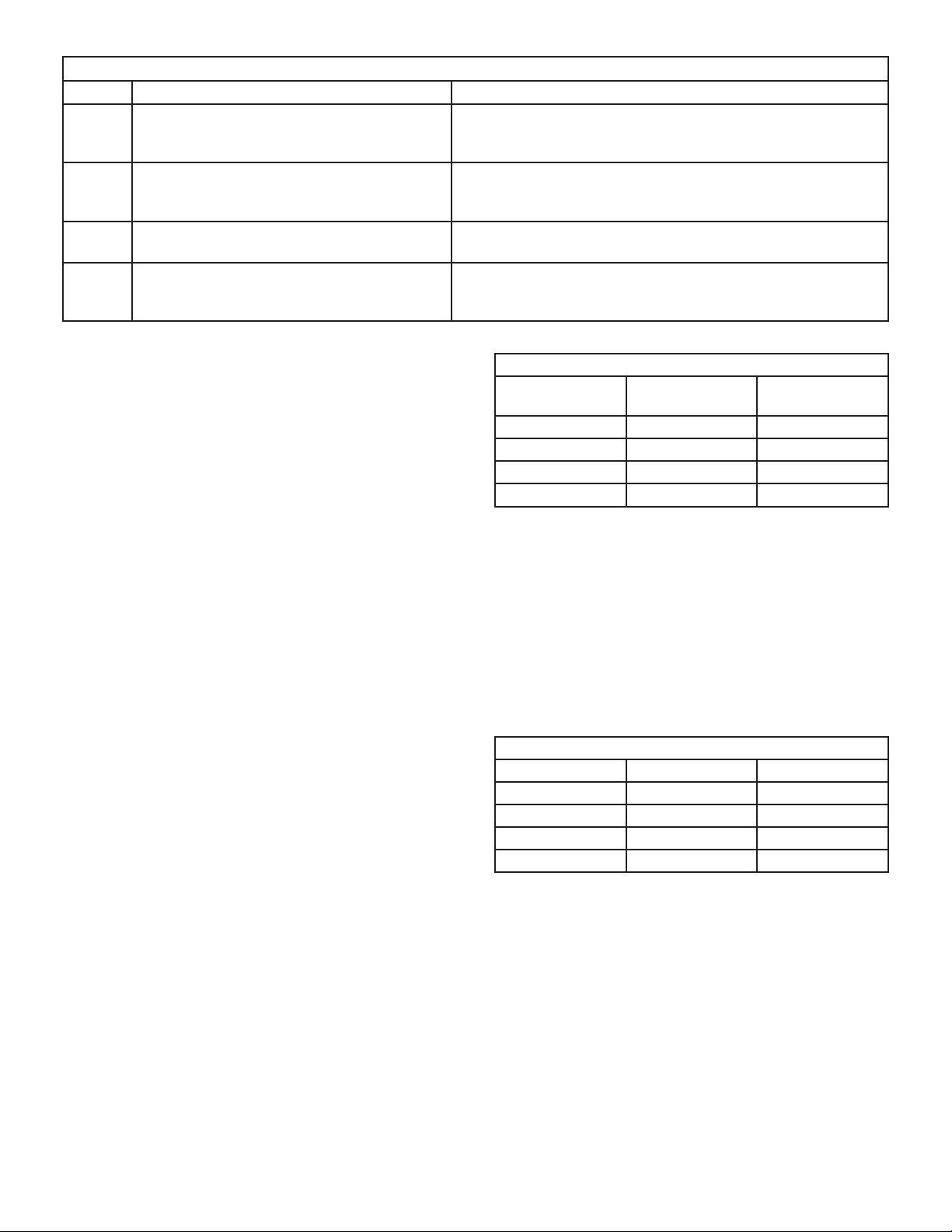
TABLE 5 Continued
Code Diagnostic Codes/Status of Equipment Action Required to Clear and Recover
E406 LSOM - Compressor open start circuit. Required amount of current is not passing through Start cur-
rent transformer. Clears the error after current is sensed in
START sensor, or after power reset.
E407 LSOM - Compressor open run circuit. Required amount of current is not passing through Run current
transformer. Clears the error after current is sensed in RUN
sensor, or 1 normal compressor run cycle, or after power reset.
E408 LSOM - Compressor contactor is welded. Compressor runs continuously. Clears the error after 1 normal
compressor run cycle or after power reset.
E409 LSOM - Compressor low voltage. Secondary voltage is below 18VAC. After 10 minutes, oper-
ation is discontinued. Clears the code after voltage is higher
than 20 VAC for 2 seconds or after power reset.
DIP Switch Settings
NOTE - All icomfort settings are set at the icomfort Wi-Fi
®
thermostat. See icomfort installation instruction. In icomfort communication system all DIP switch and clippable
link settings are ignored. For conventional thermostats
proceed with DIP switch and clippable link settings as outlined in the following.
Heating Operation DIP Switch Settings
Switch 1 -- Thermostat Selection -- This unit may be
used with either a single-stage or two-stage thermostat.
The thermostat selection is made using a DIP switch
which must be properly positioned for the particular application. The DIP switch is factory-positioned for use with a
twostage thermostat. If a single-stage thermostat is to be
used, the DIP switch must be repositioned.
a. Select “OFF” for two-stage heating operation controlled by a
two-stage heating thermostat (factory setting);
b. Select “ON” for two-stage heating operation controlled by
a single-stage heating thermostat. This setting provides a
timed delay before second-stage heat is initiated.
Switch 2 -- Second Stage Delay (Used with SingleStage Thermostat Only) -- This switch is used to deter-
mine the second stage on delay when a single-stage thermostat is being used. The switch is factory-set in the OFF
position, which provides a 7-minute delay before secondstage heat is initiated. If the switch is toggled to the ON
position, it will provide a 12-minute delay before secondstage heat is initiated. This switch is only activated when
the thermostat selector jumper is positioned for SINGLEstage thermostat use.
Switches 3 and 4 -- Blower-Off Delay -- The blower-on
delay of 30 seconds is not adjustable. The blower-off delay (time that the blower operates after the heating demand has been satisfi ed) can be adjusted by moving
switches 3 and 4 on the integrated control. The unit is
shipped from the factory with a blower-off delay of 90 seconds. The blower off delay affects comfort and is adjustable to atisfy individual applicationsAdjust the blower off
delay to achieve a supply air temperature between 90°
and 110°F at the exact moment that the blower is de-energized. Longer off delay settings provide lower supply air
temperatures; shorter settings provide higher supply air
temperatures. Table 6 provides the blower off timings that
will result from different switch settings.
TABLE 6
Blower Off Delay Switch Settings
Blower Off Delay
Seconds
60 On Off
90 (factory) Off Off
120 Off On
180 On On
Switch 3 Switch 4
Indoor Blower Operation DIP Switch Settings
Switches 5 and 6 -- Cooling Mode Blower Speed -- The
unit is shipped from the factory with the dip switches positioned for high speed (4) indoor blower motor operation
during the cooling mode. Table 7 provides the cooling
mode blower speeds that will result from different switch
settings. Switches 5 and 6 set the blower cfm for secondstage cool. The integrated control automatically ramps
down to 70% of the second-stage cfm for fi rst-stage cfm.
Refer to tables for corresponding cfm values.
TABLE 7
Cooling Mode Blower Speeds
Speed Switch 5 Switch 6
Low On On
Medium Low Off On
Medium High On Off
High (factory) Off Off
. Switches 7 and 8 -- Cooling Blower Speed Adjust-
ment
-- The unit is shipped from the factory with the dip switches
positioned for NORMAL (no) adjustment. The dip switches
may be positioned to adjust the blower speed by +10% or
-10% to better suit the application. Table 8 below provides
blower speed adjustments that will result from different
switch settings. Refer to tables for corresponding cfm values.
Page 14
Page 15
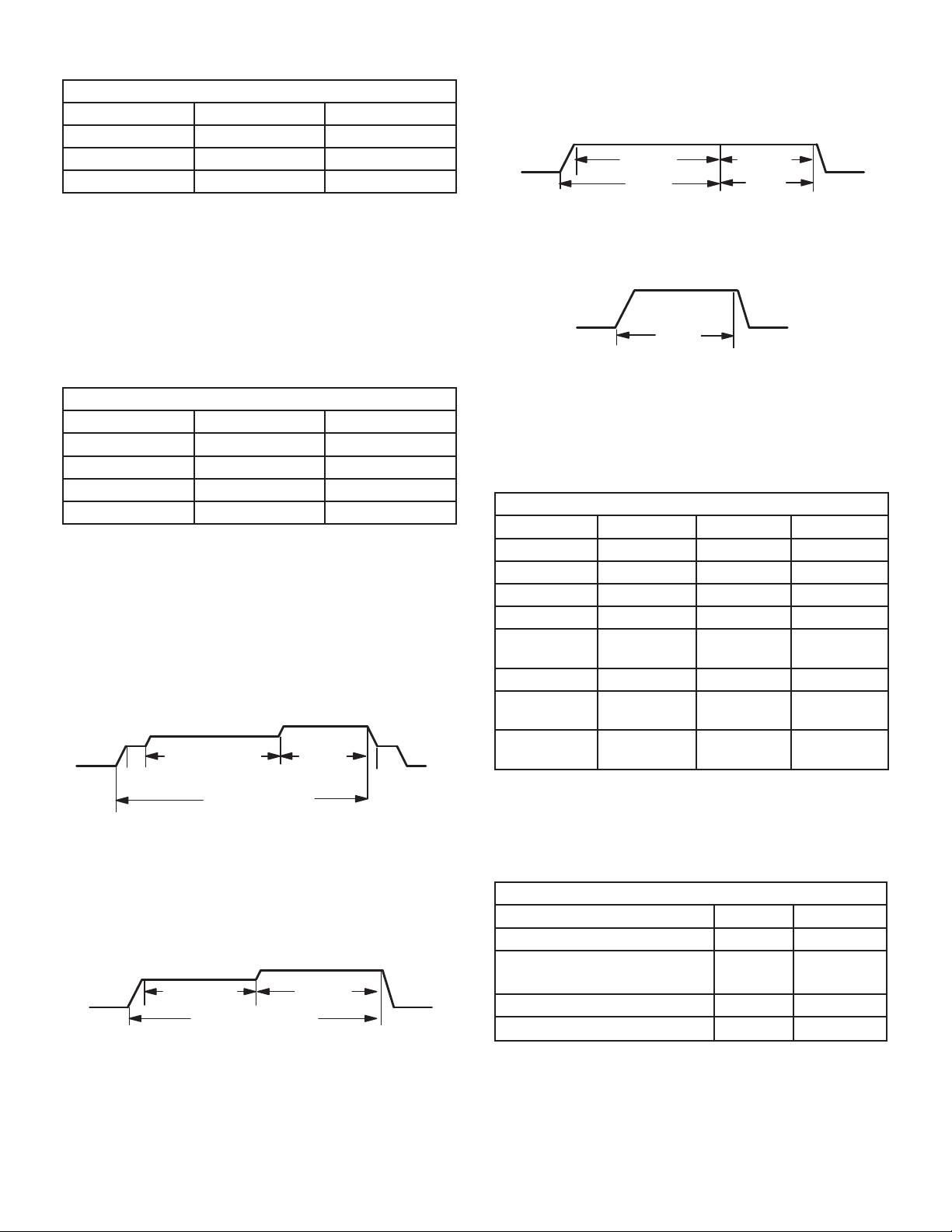
TABLE 8
Cooling Blower Speed Adjustment
Adjustment Switch 7 Switch 8
+10% (approx) On Off
Factory Default Off Off
-10% (approx) Off Off
Ramping Option C
• Motor runs at 100% until demand is satisfi ed.
• Once demand is met, motor runs at 100% for 45 sec-
onds then ramps down to stop.
OFF
100% CFM
COMPRESSOR
DEMAND
100% CFM
45 SEC.
OFF
Switches 9 and 10 -- Cooling Mode Blower Speed
Ramping -- Blower speed ramping may be used to en-
hance dehumidifi cation performance. The switches are
factory set at option A which has the greatest effect on dehumidifi cation performance. Table 9 provides the cooling
mode blower speed ramping options that will result from
different switch settings. The cooling mode blower speed
ramping options are detailed below.
TABLE 9
Cooling Mode Blower Speed Ramping
Ramping Switch 9 Switch 10
A (Factory) Off Off
BOffOn
COnOff
DOnOn
Ramping Option A (Factory Selection)
• Motor runs at 50% for 30 seconds.
• Motor then runs at 82% for approximately 7-1/2 minutes.
• If demand has not been satisfi ed after 7-1/2 minutes,
motor runs at 100% until demand is satisfi ed.
• Once demand is met, motor runs at 50% for 30 seconds then ramps down to stop.
OFF
1/2 MIN
50% CFM
7 1/2 MIN
82% CFM
COMPRESSOR DEMAND
100%
CFM
1/2 MIN
50% CFM
OFF
Ramping Option D
• Motor runs at 100% until demand is satisfi ed.
• Once demand is met, motor ramps down to stop.
100% CFM
COMPRESSOR
DEMAND
OFFOFF
Switches 11, 12 and 13 -- Heating Mode Blower Speed
The switches are factory set to the OFF position which
provides factory default heat speed. Refer to Table 10 for
switches 11, 12 and 13 that provided the corresponding
increases or decrease to both high and low heat demand.
TABLE 10
Heating Mode Blower Speeds
Heat Speed Switch 11 Switch 12 Switch 13
Increase 24% On On On
Increase 18% On On Off
Increase 12% On Off On
Increae 6% On Off Off
Factory
Off Off Off
Default
Decrease 6% Off Off On
Decrease
Off On Off
12%
Decrease
Off On On
18%
Switches 14 and 15 -- Continuous Blower Speed --
Table 11 provides continuous blower speed adjustments
that will result from different switch settings.
Ramping Option B
• Motor runs at 82% for approximately 7-1/2 minutes. If
demand has not been satisfi ed after 7-1/2 minutes,mo-
tor runs at 100% until demand is satisfi ed.
• Once demand is met, motor ramps down to stop.
OFF
7 1/2 MIN
82%CFM
COMPRESSOR DEMAND
100% CFM
OFF
Page 15
TABLE 11
Continuous Blower Speed
Coninuous Blower Speed Switch 14 Switch 15
28% of High Cool Speed Off On
38% of High Cool Speed
(Factory)
70% of High Cool Speed On Off
100% of High Cool Speed On On
Off Off
Page 16

BLOWER DATA
SL280UH060NV36A BLOWER PERFORMANCE (less fi lter)
BOTTOM RETURN AIR
0 through 0.8 in. w.g. (Heating) and 0 through 1.0 in. w.g. (Cooling) External Static Pressure Range
HEATING
1
Heating Speed
DIP Switch
Settings
+24% 1030 1140
+18% 965 1075
+12% 925 1020
+6% 870 965
Factory Default 825 915
–6% 775 865
–12% 735 810
–18% 685 760
1
Cooling Speed
DIP Switch
Settings
Low Medium-Low Medium-High
+ 595 715 815 920 845 1015 1175 1340
Factory Default 565 680 735 840 790 945 1070 1215
– 510 610 695 780 715 845 980 1120
First Stage Heating Speed - cfm Second Stage Heating Speed - cfm
COOLING
First Stage Cooling Speed - cfm Second Stage Cooling Speed - cfm
2
High Low Medium-Low Medium-High
2
High
SL280UH060NV36A BLOWER PERFORMANCE (less fi lter)
SINGLE SIDE RETURN AIR
0 through 0.8 in. w.g. (Heating) and 0 through 1.0 in. w.g. (Cooling) External Static Pressure Range
HEATING
1
Heating Speed
DIP Switch
First Stage Heating Speed - cfm Second Stage Heating Speed - cfm
Settings
+24% 985 1100
+18% 950 1050
+12% 875 1000
+6% 850 935
Factory Default 800 890
–6% 750 840
–12% 700 790
–18% 680 740
COOLING
1
Cooling Speed
DIP Switch
Settings
Low Medium-Low Medium-High
First Stage Cooling Speed - cfm Second Stage Cooling Speed - cfm
2
High Low Medium-Low Medium-High
2
High
+ 575 700 800 890 835 990 1145 1300
Factory Default 535 630 745 825 760 890 1020 1185
– 475 580 645 750 690 820 950 1055
1
Cooling and heating speeds are based on a combination of DIP switch settings on the furnace control. Refer to Installation Instructions for specifi c DIP Switch Settings.
2
Factory default setting.
NOTES - The effect of static pressure is included in air volumes shown.
First stage HEAT is approximately 91% of the same second stage HEAT.
First stage COOL (two-stage air conditioning units only) is approximately 70% of the same second stage COOL speed position.
Continuous Fan Only speed is selectable at 28%, 38%, 70% and 100% of the selected second stage cooling speed - minimum 250 cfm.
Lennox iHarmony® Zoning System Applications - Minimum blower speed is 250 cfm.
Page 16
Page 17

BLOWER DATA
SL280UH080NV48B BLOWER PERFORMANCE (less fi lter)
BOTTOM RETURN AIR
0 through 0.8 in. w.g. (Heating) and 0 through 1.0 in. w.g. (Cooling) External Static Pressure Range
HEATING
1
Heating Speed
DIP Switch
Settings
+24% 1350 1500
+18% 1270 1420
+12% 1200 1340
+6% 1130 1270
Factory Default 1060 1190
–6% 970 1130
–12% 880 1025
–18% 845 950
1
Cooling Speed
DIP Switch
Settings
Low Medium-Low Medium-High
+ 640 870 1030 1200 1020 1310 1535 1750
Factory Default 590 770 925 1100 935 1200 1400 1600
– 545 635 750 960 815 1080 1260 1430
First Stage Heating Speed - cfm Second Stage Heating Speed - cfm
COOLING
First Stage Cooling Speed - cfm Second Stage Cooling Speed - cfm
2
High Low Medium-Low Medium-High
2
High
SL280UH080NV48B BLOWER PERFORMANCE (less fi lter)
SINGLE SIDE RETURN AIR
0 through 0.8 in. w.g. (Heating) and 0 through 1.0 in. w.g. (Cooling) External Static Pressure Range
HEATING
1
Heating Speed
DIP Switch
First Stage Heating Speed - cfm Second Stage Heating Speed - cfm
Settings
+24% 1245 1385
+18% 1180 1320
+12% 1130 1245
+6% 1045 1185
Factory Default 1095 1120
–6% 1020 1050
–12% 825 975
–18% 840 865
COOLING
1
Cooling Speed
DIP Switch
Settings
Low Medium-Low Medium-High
First Stage Cooling Speed - cfm Second Stage Cooling Speed - cfm
2
High Low Medium-Low Medium-High
2
High
+ 600 810 995 1165 995 1265 1490 1680
Factory Default 560 705 855 1050 905 1140 1350 1525
– 540 585 750 910 735 1010 1200 1365
1
Cooling and heating speeds are based on a combination of DIP switch settings on the furnace control. Refer to Installation Instructions for specifi c DIP Switch Settings.
2
Factory default setting.
NOTES - The effect of static pressure is included in air volumes shown.
First stage HEAT is approximately 91% of the same second stage HEAT.
First stage COOL (two-stage air conditioning units only) is approximately 70% of the same second stage COOL speed position.
Continuous Fan Only speed is selectable at 28%, 38%, 70% and 100% of the selected second stage cooling speed - minimum 380 cfm.
Lennox iHarmony
®
Zoning System Applications - Minimum blower speed is 380 cfm.
Page 17
Page 18

BLOWER DATA
SL280UH080NV48B BLOWER PERFORMANCE (less fi lter)
SIDE RETURN AIR WITH OPTIONAL RETURN AIR BASE
0 through 0.8 in. w.g. (Heating) and 0 through 1.0 in. w.g. (Cooling) External Static Pressure Range
HEATING
1
Heating Speed
DIP Switch
Settings
+24% 1300 1445
+18% 1230 1355
+12% 1145 1300
+6% 1215 1225
Factory Default 1015 1150
–6% 1050 1070
–12% 860 1000
–18% 750 935
1
Cooling Speed
DIP Switch
Settings
Low Medium-Low Medium-High
+ 625 835 1000 1190 1000 1280 1500 1715
Factory Default 590 760 910 1070 910 1180 1360 1560
– 540 655 800 940 760 1040 1230 1380
First Stage Heating Speed - cfm Second Stage Heating Speed - cfm
COOLING
First Stage Cooling Speed - cfm Second Stage Cooling Speed - cfm
2
High Low Medium-Low Medium-High
2
High
SL280UH080NV60C BLOWER PERFORMANCE (less fi lter)
BOTTOM RETURN AIR, RETURN AIR FROM BOTH SIDES OR RETURN AIR FROM BOTTOM AND ONE SIDE
0 through 0.8 in. w.g. (Heating) and 0 through 1.0 in. w.g. (Cooling) External Static Pressure Range
HEATING
1
Heating Speed
DIP Switch
First Stage Heating Speed - cfm Second Stage Heating Speed - cfm
Settings
+24% 1375 1530
+18% 1330 1450
+12% 1260 1390
+6% 1185 1315
Factory Default 1130 1235
–6% 1050 1165
–12% 980 1090
–18% 940 1020
COOLING
1
Cooling Speed
DIP Switch
Settings
Low Medium-Low Medium-High
First Stage Cooling Speed - cfm Second Stage Cooling Speed - cfm
2
High Low Medium-Low Medium-High
+ 1080 1235 1410 1655 1540 1745 2000 2300
Factory Default 975 1125 1290 1500 1390 1595 1815 2130
– 880 1010 1165 1360 1265 1440 1630 1930
2
High
1
Cooling and heating speeds are based on a combination of DIP switch settings on the furnace control. Refer to Installation Instructions for specifi c DIP Switch Settings.
2
Factory default setting.
NOTES - The effect of static pressure is included in air volumes shown.
First stage HEAT is approximately 91% of the same second stage HEAT.
First stage COOL (two-stage air conditioning units only) is approximately 70% of the same second stage COOL speed position.
Continuous Fan Only speed is selectable at 28%, 38%, 70% and 100% of the selected second stage cooling speed - minimum 380 cfm.
Lennox iHarmony
®
Zoning System Applications - Minimum blower speed is 380 cfm for 08048B and 450cfm for 08060C
Page 18
Page 19

BLOWER DATA
SL280UH080NV60C BLOWER PERFORMANCE (less fi lter)
Single Side Return Air - Air volumes in bold require Optional Return Air base and fi eld fabricated transition to accommodate 20 x
25 x 1 in. air fi lter in order to maintain proper air velocity.
0 through 0.8 in. w.g. (Heating) and 0 through 1.0 in. w.g. (Cooling) External Static Pressure Range
HEATING
1
Heating Speed
DIP Switch
Settings
+24% 1350 1485
+18% 1280 1420
+12% 1220 1345
+6% 1155 1270
Factory Default 1100 1200
–6% 1020 1135
–12% 965 1070
–18% 870 980
1
Cooling Speed
DIP Switch
Settings
Low Medium-Low Medium-High
+ 1050 1180 1350 1570 1500 1700 1915 2240
Factory Default 960 1080 1225 1420 1370 1540 1760 2035
– 845 950 1110 1290 1235 1390 1570 1840
First Stage Heating Speed - cfm Second Stage Heating Speed - cfm
COOLING
First Stage Cooling Speed - cfm Second Stage Cooling Speed - cfm
2
High Low Medium-Low Medium-High
2
High
Page 19
Page 20

BLOWER DATA
SL280UH100NV60C BLOWER PERFORMANCE (less fi lter)
BOTTOM RETURN AIR, RETURN AIR FROM BOTH SIDES OR RETURN AIR FROM BOTTOM AND ONE SIDE
0 through 0.8 in. w.g. (Heating) and 0 through 1.0 in. w.g. (Cooling) External Static Pressure Range
HEATING
1
Heating Speed
DIP Switch
Settings
+24% 1745 1930
+18% 1670 1825
+12% 1580 1740
+6% 1500 1655
Factory Default 1425 1565
–6% 1310 1470
–12% 1260 1390
–18% 1190 1300
1
Cooling Speed
DIP Switch
Settings
Low Medium-Low Medium-High
+ 1200 1250 1380 1585 1710 1790 1950 2270
Factory Default 1075 1150 1275 1460 1570 1610 1785 2065
– 1010 1050 1150 1320 1410 1480 1625 1880
First Stage Heating Speed - cfm Second Stage Heating Speed - cfm
COOLING
First Stage Cooling Speed - cfm Second Stage Cooling Speed - cfm
2
High Low Medium-Low Medium-High
2
High
SL280UH100NV60C BLOWER PERFORMANCE (less fi lter)
Single Side Return Air - Air volumes in bold require Optional Return Air base and fi eld fabricated transition to accommodate 20 x
25 x 1 in. air fi lter in order to maintain proper air velocity.
0 through 0.8 in. w.g. (Heating) and 0 through 1.0 in. w.g. (Cooling) External Static Pressure Range
HEATING
1
Heating Speed
DIP Switch
First Stage Heating Speed - cfm Second Stage Heating Speed - cfm
Settings
+24% 1600 1785
+18% 1530 1685
+12% 1440 1600
+6% 1370 1515
Factory Default 1290 1415
–6% 1260 1390
–12% 1175 1290
–18% 1065 1190
COOLING
1
Cooling Speed
DIP Switch
Settings
Low Medium-Low Medium-High
First Stage Cooling Speed - cfm Second Stage Cooling Speed - cfm
2
High Low Medium-Low Medium-High
2
High
+ 1140 1180 1300 1480 1615 1695 1865 2160
Factory Default 1040 1060 1190 1365 1460 1530 1690 1960
– 930 970 1070 1240 1325 1380 1520 1760
1
Cooling and heating speeds are based on a combination of DIP switch settings on the furnace control. Refer to Installation Instructions for specifi c DIP Switch Settings.
2
Factory default setting.
NOTES - The effect of static pressure is included in air volumes shown.
First stage HEAT is approximately 91% of the same second stage HEAT.
First stage COOL (two-stage air conditioning units only) is approximately 70% of the same second stage COOL speed position.
Continuous Fan Only speed is selectable at 28%, 38%, 70% and 100% of the selected second stage cooling speed - minimum 450 cfm.
Lennox iHarmony
®
Zoning System Applications - Minimum blower speed is 450 cfm.
Page 20
Page 21

On-Board Links
Note: In icomfort systems with a conventional outdoor unit
(non-communicating), the on-board clippable links must
be set to properly confi gure the system.
damage. Refer to Table 12 for operation sequence in applications including SL280UHNV, a thermostat which features humidity control and a single-speed outdoor unit. Table 13 gives the operation sequence in applications with a
two-speed outdoor unit.
WARNING
Carefully review all confi guration information provided.
Failure to properly set DIP switches, jumpers and onboard links can result in improper operation!
On-Board Link W914 Dehum or Harmony (R to DS)
On-board link W914, is a clippable connection between
terminals R and DS on the integrated control. W914 must
be cut when the furnace is installed with either the Harmony III zone control or a thermostat which features humidity
control. If the link is left intact the PMW signal from the
Harmony III control will be blocked and also lead to control
On-Board Link W951 Heat Pump (R to O)
On-board link W951 is a clippable connection between
terminals R and O on the integrated control. W951 must
be cut when the furnace is installed in applications which
include a heat pump unit and a thermostat which features
dual fuel use. If the link is left intact, terminal “O” will remain energized eliminating the HEAT MODE in the heat
pump.
On-Board Link W915 2 Stage Compr (Y1 to Y2)
On-board link W915 is a clippable connection between
terminals Y1 and Y2 on the integrated control. W915 must
be cut if two-stage cooling will be used. If the Y1 to Y2 link
is not cut the outdoor unit will operate in second-stage
cooling only.
TABLE 12
OPERATING SEQUENCE
SL280UHV, Non-Communicating Thermostat with Humidity Control Feature and Single-Speed Outdoor Unit
OPERATING SEQUENCE SYSTEM DEMAND SYSTEM RESPONSE
System
Condition
NO CALL FOR DEHUMIDIFICATION
Normal Operation 1 On On On Acceptable
BASIC MODE (only active on a Y1 thermostat demand)
Normal Operation 1 On On On Acceptable
Dehumidifi cation
call
PRECISION MODE (operates independent of a Y1 demand)
Normal Operation 1 On On On Acceptable
Dehumidifi cation
Call
Dehumidifi cation
Call Only
Dave Lennox ComfortSense® 7500 thermostat to use for this application - Y2081 4 heat / 2 cool
*Dehumidifi cation blower speed is 70% of COOL speed for all units .
**In Precision mode, ComfortSense® 7000 thermostat will maintain room temperature up to 2 °F (1.2°C) cooler than room setting.
Step
2 On On On Demand 0 VAC High 70%*
2 On On On Demand 0 VAC High 70%*
1 On On On Demand 0 VAC High 70%*
Jumpers at indoor unit with a single stage outdoor unit. With Condensing unit - Cut
W914 (R to DS) on SureLight® control With Heat Pump - Cut W914 (R to DS) &
W951 (R to O) on SureLight® control
Thermostat Demand Relative Humidity
Y1 O G W1 Status D
24
VAC
24
VAC
24
VAC
Compre
ssor
High 100%
High 100%
High 100%
Blower
CFM
(cool)
Comments
Compressor and
indoor blower follow
thermostat demand
ComfortSense® 7500
thermostat energizes
Y1 and de-energizes
D on a call for de-
humidifi cation
Dehumidifi cation
mode begins when
humidity is greater
than set point
ComfortSense®
7500 thermostat will
try to maintain room
humidity setpoint by
allowing the room
space to maintain
a cooler room
thermostat setpoint**
Page 21
Page 22

TABLE 13
OPERATING SEQUENCE
SL280UHV, Non-Communicating Thermostat with Humidity Control Feature and Two-Speed Outdoor Unit
OPERATING
SEQUENCE
System
Condition
Step
NO CALL FOR DEHUMIDIFICATION
Normal Operation
Y1
Normal Operation
Y2
1 On On On Acceptable
2 On On On On Acceptable
ROOM THERMOSTAT CALLS FOR FIRST STAGE COOLING
BASIC MODE (only active on a Y1 thermostat demand)
Normal Operation 1 On On On Acceptable
Dehumidifi cation
call
2 On On On On Demand
PRECISION MODE (operates independent of a Y1 demand)
Normal Operation 1 On On On Acceptable
Dehumidifi cation
Call
Dehumidifi cation
Call Only
2 On On On On Demand
1 On On On On Demand
ROOM THERMOSTAT CALLS FOR FIRST AND SECOND STAGE COOLING
BASIC MODE (only active on a Y1 thermostat demand)
Normal Operation 1 On On On On Acceptable
Dehumidifi cation
Call
2 On On On On Demand
PRECISION MODE (operates independent of a Y1 thermostat demand)
Normal Operation 1 On On On Acceptable
Dehumidifi cation
Call
Dehumidifi cation
Call ONLY
2 On On On On Demand
1 On On On On Demand
Jumpers at indoor unit with a two stage outdoor unit
Cut factory jumper from Y1 to Y2 or cut W915 (Y1 to Y2)
With Condensing unit - Cut W914 (R to DS) on SureLight® control
With Heat Pump - Cut W914 (R to DS) & W951 (R to O) on SureLight® control
Dave Lennox ComfortSense® 7500 thermostat to use for this application - Y2081 4 heat / 2 cool
*Normal operation fi rst stage cooling blower speed is 70% COOL speed.
**Dehumidifi cation blower speed is, reduced to 70% of COOL.
***In Precision mode, ComfortSense® 7000 thermostat will maintain room temperature up to 2 °F (1.2°C) cooler than room setting.
SYSTEM DEMAND SYSTEM RESPONSE
Thermostat Demand Relative Humidity
Y1 Y2 O G W1 W2 Status D
24
VAC
24
VAC
24
VAC
0
VAC
24
VAC
0
VAC
0
VAC
24
VAC
0
VAC
24
VAC
0
VAC
0
VAC
Compre
ssor
Low 70%*
High 100%
Low 70%*
High 70%**
Low 70%*
High 70%**
High 70%**
High 100%
High 70%**
Low 70%*
High 70%**
High 70%**
Blower
CFM
(cool)
Comments
Compressor and indoor
blower follow thermostat
demand
ComfortSense® 7500
thermostat energizes Y1
and de-energizes D on a
call for de-humidifi cation
Dehumidifi cation mode
begins when humidity is
greater than set point
ComfortSense® 7500
thermostat will try to
maintain room humidity
setpoint by allowing the
room space to maintain
a cooler room thermostat
setpoint**
ComfortSense® 7500
thermostat energizes Y2
and de-energizes D on a
call for de-humidifi cation
Dehumidifi cation mode
begins when humidity is
greater than set point
ComfortSense® 7500
thermostat will try to
maintain room humidity
setpoint by allowing the
room space to maintain
a cooler room thermostat
setpoint***
Page 22
Page 23

B- Indoor Blower Motor
Power Choke
(4 and 5 Ton Only)
To Remove Blower From Unit: Remove access panels,
Control box, Bolts and Wiring Jackplugs.
Blower Motor
(B3)
Then Slide Out Front of Unit.
FIGURE 6
WARNING
During blower operation, the ECM motor emits
energy that may interfere with pacemaker operation.
Interference is reduced by both the sheet metal cabinet
and distance.
During blower operation, the ECM motor emits energy
that may interfere with pacemaker operation. Interference
is reduced by both the sheet metal cabinet and distance.
The motor communicates with the integrated control via
a 2-way serial connection. The motor receives all necessary functional parameters from the integrated control
and does not rely on a factory program like traditional variable speed motors. SL280UHNV units use a three-phase,
electronically controlled D.C. brushless motor (controller
converts single phase a.c. to three phase D.C.), with a
permanent-magnettype rotor (Figure 7). Because this motor has a permanent magnet rotor it does not need brushes like conventional D.C. motors.
The stator windings are split into three poles which are
electrically connected to the controller. This arrangement
allows motor windings to turn on and off in sequence by
the controller.
IMPORTANT
Earlier ECM motors used on other Lennox furnace
models are not interchangeable with motors used on the
SL280UH furnace line.
A solid-state controller is permanently attached to the motor. The controller is primarily an A.C. to D.C. converter.
Converted D.C. power is used to drive the motor. The controller contains a microprocessor which monitors varying
conditions inside the motor (such as motor workload).
BLOWER MOTOR COMPONENTS
STATOR
(WINDINGS)
BEARING
ROTOR
FIGURE 7
The controller uses sensing devices to sense what position the rotor is in at any given time. By sensing the position of the rotor and then switching the motor windings on
and off in sequence, the rotor shaft turns the blower.
All SL280UHNV blower motors use single phase power.
An external run capacitor is not used. The motor uses permanently lubricated ball-type bearings.
Internal Operation
The motor is controlled via serial communication between
the integrated control on the furnace and the controller
attached to the motor shell. The messages sent back and
forth between the two controls serve to communicate rotational direction, demand, motor size, current draw, torque,
and rpm, among other variables.
Motor rpm is continually adjusted internally to maintain
constant static pressure against the blower wheel. The
controller monitors the static work load on the motor and
motor ampdraw to determine the amount of rpm adjustment. Blower rpm may be adjusted any amount in order to
maintain a constant cfm as shown in Blower Ratings Tables. The cfm remains relatively stable over a broad range
of static pressure. Since the blower constantly adjusts rpm
to maintain a specifi ed cfm, motor rpm is not rated. Hence,
the terms “cool speed”, “heat speed ” or “speed tap” in
this manual, on the unit wiring diagram and on blower B3,
refer to blower cfm regardless of motor rpm.
Initial Power Up
When line voltage is applied to B3, there will be a large
inrush of power lasting less than 1/4 second. This inrush
charges a bank of DC fi lter capacitors inside the controller.
If the disconnect switch is bounced when the disconnect is
closed, the disconnect contacts may become welded. Try
not to bounce the disconnect switch when applying power
to the unit.
Page 23
Page 24

Motor Start-Up
When B3 begins start-up, the motor gently vibrates back
and forth for a moment. This is normal. During this time
the electronic controller is determining the exact position
of the rotor. Once the motor begins turning, the controller
slowly eases the motor up to speed (this is called “softstart”). The motor may take as long as 10-15 seconds
to reach full speed. If the motor does not reach 200 rpm
within 13 seconds, the motor shuts down. Then the motor
will immediately attempt a restart. The shutdown feature
provides protection in case of a frozen bearing or blocked
blower wheel. The motor may attempt to start eight times.
If the motor does not start after the eighth try, the controller locks out. Reset controller by momentarily turning off
power to unit.
The DC fi lter capacitors inside the controller are connect-
ed electrically to the motor supply wires. The capacitors
take approximately 5 minutes to discharge when the disconnect is opened. For this reason it is necessary to wait
at least 5 minutes after turning off power to the unit before
attempting to service motor.
DANGER
Disconnect power from unit and wait at least
fi ve minutes to allow capacitors to discharge
before attempting to service motor. Failure to
wait may cause personal injury or death.
Troubleshooting Motor Operation
To verify motor operation see steps below and Figure 8
and Figure 9.
1 - Remove J48 (5 pin power plug) from P48 on the
motor.
2 - With the power on at the furnace and door switch
depressed, use a test meter to verify 120V between
pins 4 and 5 on J48.
3 - Reconnect J48 to P48 on the motor.
4 - Remove J49 (4 pin low voltage connector) from P49
on the motor.
5 - Using test jumpers, apply 24V to pins 3 and 4 on
P49 on the motor.
Note: Do not apply 24V to pins 2 and 4 on P49. Doing so
will cause permanent damage to the motor.
6 - 6- Motor should run at 75%.
7 - Test is complete. Remove jumpers and reconnect
plugs.
Another option is to use the TECMate PRO motor tester
with the 16 to 4 pin adaptor. The use of the TECMate PRO
isolates the motor from the integrated control. Follow the
instructions provided with the kit. If the motor runs do not
replace.
Power Choke (L13)
A choke coil is used on SL280UHNV 4 and 5 ton units
equipped with 1 hp motors. The choke is located on the
blower housing and is used to suppress transient current
spikes.
Page 24
Page 25

BLOWER B3 HARNESS CONNECTORS
P48 5 Pin
SHAFT
BLOWER B3 HARNESS CONNECTORS
P48 5 Pin
P49 4 Pin
SHAFT
MOTOR with INTEGRATED
CONTROLLER
J48 5 Pin
J49 4 Pin
J49 4 Pin Control Connector
J48 5 Pin Line Voltage Connector
P49 4 Pin
MOTOR with INTEGRATED
CONTROLLER
P48 5 Pin
P49 4 Pin
1
2
3
4
5
120v
0
J48 Connector
240v
FIGURE 8
J48 Connector
installed on motor
P49 4 Pin
24v Transformer
J49 Connector
FIGURE 9
Page 25
Page 26

Troubleshooting Motor Windings
Ensure that motor windings are not damaged by performing the following tests:
NOTE - If your ohm meter is not an auto-ranging type, set
it to the highest ohm scale (100k ohms or greater) before
performing tests.
TABLE 14
Ohm Meter Range
Scale Measurement Range
In Words ohms
2M two megohm - two
million ohms
200k two hundred kilohm
- two hundred
thousand ohms
20k twenty kilohm --
twenty thousand
ohms
2k two kilohm -- two
thousand ohms
200 two hundred ohm 0 - 200
0 - 2,000,000
0 - 200,000
0-20,000
0 - 2,000
TEST A
Measure the resistance between each of the three motor
leads (3-pin plug) and the unpainted part of the end shield.
If the winding resistance to ground is <100k ohms, replace the motor and control module. If the resistance
to ground is >100k, the motor windings are fi ne. Pro-
ceed to Test B.
Test A
FIGURE 11
TEST B
Use an ohmmeter to measure the motor phase-to-phase
resistance by checking these combinations of the the 3-pin
motor plug. For the purpose of this test, start at either end
of the connector as lead 1.
1 - The lead-to-lead resistance across any two leads
should be less than 20 ohms.
2 - Each lead-to-lead resistance should be the same.
If the measured resistance is greater than 20 ohms, replace the motor and control module.
FIGURE 10
Test B
FIGURE 12
Page 26
Page 27

C- Heating Components
1. Ignitor
The SureLight® ignitor is made of durable silicon nitride.
Ignitor longevity is enhanced by controlling voltage to the
ignitor. The integrated control provides a regulated 120
volts to the ignitor for a consistent ignition and long ignitor
life. Ohm value should be 39 to 70. See Figure 13 for ignitor location and Figure 14 for ignitor check out.
NOTE - The SL280UHNV furnace contains electronic
components that are polarity sensitive. Make sure that the
furnace is wired correctly and is properly grounded.
2. Flame Sensor
A fl ame sensor is located on the top of the air gas ple-
num. See Figure 13. The sensor can be removed for service without removing the the burner. During operation,
fl ame is sensed by current passed through the fl ame and
sensing electrode. The SureLight control allows the gas
valve to remain open as long as fl ame signal is sensed.
To check fl ame sense signal use the push-button found
on the integrated control and go to Field Test Mode. The
menu will display the fl ame signal. See Table 15 for fl ame
signal.
TABLE 15
Flame Signal in Microamps
Normal Low Drop Out
2.6 or greater 2.5 or less 1.1
3. Gas Valve
The valve (Figure 16) is internally redundant to assure
safety shut-off. If the gas valve must be replaced, the
same type valve must be used.
24VAC terminals and gas control knob are located on the
valve. A wire harness connects the terminals from the gas
valve to the electronic ignition control. 24V applied to the
terminals energizes the valve. Inlet and outlet pressure
taps are located on the valve. A regulator adjustment
screw is located on the valve.
4. Thermal Switch
The auto-reset switch is located on the front of the intake
air elbow. The switch will safely shut the unit down if excessive temperatures are detected. See Figure 13. When
the switch senses excessive temperature, the circuit
breaks and the ignition control immediately stops ignition
and closes the gas valve.
5. Burner and Orifi ce
Burners are factory set and require no adjustment. Always
operate the unit with air gas plenum in place. The burner has one orifi ce located between the gas valve and the
air intake assembly (Figure 13). To check or replace the
orifi ce remove the intake air screen, coupling and intake
air elbow.Using a 5/8” socket, go through the elbow and
unscrew the gas orifi ce. The burner uses an orifi ce (see
Table 16) that is precisely matched to the burner input.
The burner can be removed for service. If burner has been
removed, it is critical to replace all gaskets.
TABLE 16
Gas Orifi ces
Unit Input Orifi ce Size (0 - 4500 ft)
060 0.0595
080 0.0689
100 0.0810
6. Primary Limit Control (S10)
The primary limit (S10) is located in the heating vestibule
panel. When excess heat is sensed in the heat exchanger,
the limit will open. If the limit is open, the furnace control
energizes the supply air blower and closes the gas valve.
The limit automatically resets when unit temperature returns to normal. The switch must reset within three minutes or the SureLight control will go into Watch guard for
one hour. The switch is factory set and cannot be adjusted. The switch may have a different set point for each unit
model number. See Lennox Repair Parts Handbook if limit
switch must be replaced.
Page 27
Page 28

Gas Valve
Orifice Housing
Gas Orifice
Air Orifice
HEATING COMPONENTS
Air Gas Plenum
Sensor
Ignitor
Burner
Gasket
Intake Air Screen
Intake Air
Elbow
FIGURE 13
Thermal
Switch
(location)
Page 28
Page 29

Tes t 1
Remove 5-pin plug from control
Check ohms reading across terminals 1and 5
Ohm value should be between 39 - 70.
Meter
(set to ohms)
Seperate the 2-pin jack plug near the manifold
and check resistance of the ignitor. If the reading
is correct, then then there is a problem with the
wiring between the jack plug and control. If the
reading is not correct the issue is the ignitor.
Tes t 2
.
SL280UHNV Ignitor Check Out
(exploded view for clarity)
Integrated control detail
Meter
(set to ohms)
Insert meter probes into the terminals 1 and 5. (Use small
diameter probes in order to not damage plug). Check
voltage during 20 second warm up period. Voltage should
read 120 volts +
check for correct supply voltage to furnace.
10%. If voltage is above these values,
Tes t 3
Meter
(set to AC volts)
Integrated control detail
Integrated control detail
FIGURE 14
Page 29
Page 30

7. Combustion Air Inducer (B6)
All SL280UHNV units use a two-stage combustion air inducer to move air through the burners and heat exchanger during heating operation. The blower uses a 120VAC
motor. The motor operates during all heating operation
and is controlled by integrated control control A92. The inducer also operates for 15 seconds before burner ignition
(prepurge) and for 5 seconds after the gas valve closes
(postpurge). The inducer operates on low speed during
fi rststage heat, then switches to high speed for second
stage heat.
8. Combustion Air Inducer Prove Switch (S18)
SL280UHNV series units are equipped with a single combustion air proving switch (fi rst and second stage) located
near the gas valve. See Figure 15. The switch is a single-pole single-throw proving switch electrically connected to the integrated control. The purpose of the switch is
to prevent burner operation if the combustion air inducer is
not operating or if the fl ue becomes obstructed.
On heat demand (fi rst or second stage) the switch senses
that the combustion air inducer is operating. It closes a
circuit to the integrated control when pressure inside the
combustion air inducer decreases to a certain set point.
The set point is 0.20” for low heat and high heat and the
same for all SL280UHNV models. The pressure sensed
by the switch is negative relative to atmospheric pressure. If the fl ue becomes obstructed during operation, the
switch senses a loss of pressure difference and opens the
circuit to the furnace control and gas valve.
COMBUSTION AIR PRESSURE SWITCH
NOTE - The switch is factory set and is not fi eld adjust-
able. It is a safety shut-down control in the furnace and
must not be by-passed for any reason. If switch is closed
or bypassed, the control will not initiate ignition at start up.
II-Placement and Installation
Make sure unit is installed in accordance with installation
instructions and applicable codes.
III-Start-Up
A-Preliminary and Seasonal Checks
1 - Inspect electrical wiring, both fi eld and factory
installed for loose connections. Tighten as required.
2 - Check voltage at disconnect switch. Voltage must
be within range listed on the nameplate. If not,
consult the power company and have voltage
condition corrected before starting unit.
B-Heating Start-Up
WARNING
Shock and burn hazard.
SL280UHNV units are equipped with a hot surface
ignition system. Do not attempt to light manually.
1 - STOP! Read the safety information at the beginning
of this section.
2 - 2 - Set the thermostat to the lowest setting.
3 - Turn off all electrical power to the unit.
4 - This furnace is equipped with an ignition device
which automatically lights the burners. Do not try to
light the burners by hand.
5 - Remove the access panel.
6 - Turn switch on gas valve to OFF. Do not force. See
fi gure 16.
7 - Wait fi ve minutes to clear out any gas. If you then
smell gas, STOP! Immediately call your gas supplier
from a neighbor’s phone. Follow the gas supplier’s
instructions. If you do not smell gas go to next step.
Positive +
to air intake pipe
FIGURE 15
Negative -
to air intake
elbow
Page 30
Page 31

MANIFOLD PRESSURE ADJUSTMENT
(TURN CCW TO INCREASE PRESSURE)
NEGATIVE AIR
PRESSURE PORT
GAS VALVE
POSITIVE AIR
PRESSURE PORT
10 - Is pressure switch closed? Obstructed fl ue will
cause unit to shut off at pressure switch. Check fl ue
and outlet for blockages.
11 - Are fl ame rollout switches tripped? If fl ame rollout
switches are tripped, call the service technician for
inspection.
C-Safety or Emergency Shutdown
Turn off unit power. Close manual and main gas valves.
D-Extended Period Shutdown
INLET
SUPPLY
PRESSURE
TAP
GAS VALVE SHOWN IN THE ON POSITION
OUTLET
MANIFOLD
PRESSURE TAP
FIGURE 16
8 - Move switch on gas valve to ON. Do not force. See
Figure 16.
9 - Replace the access panel.
10 - Turn on all electrical power to to the unit.
11 - Set the thermostat to desired setting.
NOTE - When unit is initially started, steps 1 through 11
may need to be repeated to purge air from gas line.
Turning Off Gas To Unit
1 - Set thermostat to lowest setting.
2 - Turn off all electrical power to unit if service is to be
performed.
3 - Remove access panel.
4 - Move switch on valve to OFF. Do not force.
5 - Replace access panel.
Failure To Operate
If the unit fails to operate, check the following:
1 - Is the thermostat calling for heat?
2 - Are access panels securely in place?
3 - Is the main disconnect switch closed?
4 - Is there a blown fuse or tripped circuit breaker?
5 - Is the fi lter dirty or plugged? Dirty or plugged fi lters
will cause the limit control to shut the unit off.
6 - Is gas turned on at the meter?
7 - Is the manual main shut-off valve open?
8 - Is the internal manual shut-off valve open?
9 - Is the unit ignition system in lock out? If the unit locks
out again, call the service technician to inspect the
unit for blockages.
Turn off thermostat or set to “UNOCCUPIED” mode. Close
all gas valves (both internal and external to unit) to guarantee no gas leak into combustion chamber. Turn off power to unit. All access panels and covers must be in place
and secured.
IV-Heating System Service Checks
A-CSA Certifi cation
All units are CSA design certifi ed without modifi cations.
Refer to the SL280UHNV Installation Instruction.
B-Gas Piping
CAUTION
If a fl exible gas connector is required or allowed by the
authority that has jurisdiction, black iron pipe shall be
installed at the gas valve and extend outside the furnace
cabinet.
WARNING
Do not over torque (800 in-lbs) or under torque (350 inlbs) when attaching the gas piping to the gas valve.
Gas supply piping should not allow more than 0.5”W.C.
drop in pressure between gas meter and unit. Supply gas
pipe must not be smaller than unit gas connection.
Compounds used on gas piping threaded joints should be
resistant to action of liquefi ed petroleum gases.
C-Testing Gas Piping
IMPORTANT
In case emergency shutdown is required, turn off the
main shut-off valve and disconnect the main power to
unit. These controls should be properly labeled by the
installer.
Page 31
Page 32

When pressure testing gas lines, the gas valve must be
E
disconnected and isolated. Gas valves can be damaged if
subjected to more than 0.5 psig (14” W.C.). See Figure 17.
If the pressure is greater than 0.5psig (14”W.C.), use the
manual shut-off valve before pressure testing to isolate
furnace from gas supply.
MANUAL MAIN
SHUT-OFF VALVE
WILL NOT HOLD
NORMAL TEST
PRESSURE
1/8 NPT PLUG
CAP
ISOLATE
GAS VALVE
FURNAC
FIGURE 17
When checking piping connections for gas leaks, use
preferred means. Kitchen detergents can cause harmful
corrosion on various metals used in gas piping. Use of a
specialty Gas Leak Detector is strongly recommended. It
is available through Lennox under part number 31B2001.
See Corp. 8411-L10, for further details.
Do not use matches, candles, fl ame or any other
source of ignition to check for gas leaks.
D-Testing Gas Supply Pressure
A port on the inlet side of the gas valve provides access to
the supply pressure tap. See fi gure 16. Loosen the screw
and connect a manometer to measure supply pressure.
The minimum supply line is 4.5” w.c. And the maximum
supply line is 13.0” w.c. Tighten screw after measurements have been taken.
IMPORTANT
For safety, connect a shut-off valve between the
manometer and the gas tap to permit shut off of gas
pressure to the manometer.
E-Rate Check
Manifold Pressure Measurement
TABLE 17
Unit High Fire Low Fire
060
3.2 - 3.6 in wc 1.3 - 1.7 in wc080
100
F- Proper Combustion
Furnace should operate minimum 15 minutes with correct
gas fl ow rate before checking combustion. Take combus-
tion sample beyond the fl ue outlet. Table 18 shows ac-
ceptable combustion for ALL SL280UHNV models. The
maximum carbon monoxide reading should not exceed
100 ppm.
TABLE 18
Firing Rate CO2% For Natural
High Fire
6.0 - 7.5
Low Fire
G- Proper Gas Flow (Approximate)
Furnace should operate at least 5 minutes before check-
ing gas fl ow. Determine time in seconds for two revolu-
tions of gas through the meter. (Two revolutions assures a
more accurate time.) Divide by two and compare to time
in Table 19 below.
NOTE- To obtain accurate reading, shut off all other gas
appliances connected to meter.
TABLE 19
GAS METER CLOCKING CHART
Seconds for One Revolution
SL280N Unit
Natural
1 cu ft Dial 2 cu ft Dial
060 60 120
080 45 90
100 36 72
Natural-1000 btu/cu ft
To correctly measure manifold pressure, follow the steps
below:
1 - Remove the threaded plug from the outlet side of
the gas valve and install a fi eld-provided barbed
fi tting. Connect measuring device “+” connection to
barbed fi tting to measure manifold pressure.
2 - Start unit on low heat and allow 15 minutes for unit
to reach steady state.
3 - After allowing unit to stabilize for 15 minutes, record
manifold pressure and compare to value given in
Table 17
4 - Repeat on high heat.
5 - Shut unit off and remove manometer as soon as
an accurate reading has been obtained. Take care
to remove barbed fi tting and replace threaded plug.
6 - Start unit and perform leak check. Seal leaks if
found.
Page 32
Page 33

V-Typical Operating Characteristics
C-External Static Pressure
A-Blower Operation and Adjustment
1 - Blower operation is dependent on thermostat control
system.
2 - Generally, blower operation is set at thermostat
subbase fan switch. With fan switch in ON position,
blower operates continuously. With fan switch in
AUTO position, blower cycles with demand or runs
continuously while heating or cooling circuit cycles.
3 - Depending on the type of indoor thermostat, blower
and entire unit will be off when the system switch is
in OFF position.
B-Temperature Rise Figure 18
Temperature rise for SL280UHNV units depends on unit
input, blower speed, blower horsepower and static pressure as marked on the unit rating plate. The blower speed
must be set for unit operation within the range of “TEMP.
RISE °F” listed on the unit rating plate.
TEMPERATURE RISE
Supply Duct Temperature ________
Return Duct Temperature _ _____
Temperature Rise = ________
1 - Tap locations shown in Figure 19.
2 - Punch a 1/4” diameter hole in supply and return
air plenums. Insert manometer hose fl ush with
inside edge of hole or insulation. Seal around the
hose with permagum. Connect the zero end of the
manometer to the discharge (supply) side of the
system. On ducted systems, connect the other end
of manometer to the return duct as above.
3 - With only the blower motor running and the
evaporator coil dry, observe the manometer
reading. Adjust blower motor speed to deliver the
air desired according to the job requirements. For
heating speed external static pressure drop must
not be more than 0.5” W.C. For cooling speed
external static pressure drop must not be more than
0.8” W.C.
4 - Seal the hole when the check is complete.
EXTERNAL STATIC PRESSURE
Supply Duct Static ________
Return Duct Static + _____
Total Duct Static =
________
(dry coil)
Supply Air
Return Air
FIGURE 18
Supply Air
Return Air
FIGURE 19
or
-+
Page 33
Page 34

VI-Maintenance
Annual Furnace Maintenance
At the beginning of each heating season, and to comply
with the Lennox Limited Warranty, your system should be
checked by a licensed professional technician (or equivalent) as follows:
WARNING
Disconnect power before servicing unit..
CAUTION
Label all wires prior to disconnection when servicing
controls. Wiring errors can cause improper and
dangerous operation. Verify proper operation after
servicing.
1 - Check wiring for loose connections, voltage at
indoor unit and amperage of indoor motor.
2 - Check the condition of the belt and shaft bearings
if applicable.
3 - Inspect all gas pipe and connections for leaks.
4 - Check the cleanliness of fi lters and change if
necessary (monthly).
IMPORTANT
If a higheffi ciency fi lter is being installed as part of this
system to ensure better indoor air quality, the fi lter must
be properly sized. Higheffi ciency fi lters have a higher
static pressure drop than standardeffi ciency glass/foam
fi lters. If the pressure drop is too great, system capacity
and performance may be reduced. The pressure drop
may also cause the limit to trip more frequently during
the winter and the indoor coil to freeze in the summer,
resulting in an increase in the number of service calls.
Before using any fi lter with this system, check the
specifi cations provided by the fi lter manufacturer
against the data given in the appropriate Lennox
Product Specifi cations bulletin. Additional information is
provided in Service and Application Note ACC002
(August 2000).
WARNING
The blower access panel must be securely in place when
the blower and burners are operating. Gas fumes, which
could contain carbon monoxide, can be drawn into living
space resulting in personal injury or death.
5 - Check the condition and cleanliness of burners and
heat exchanger and clean if necessary.
6 - Check the cleanliness of blower assembly and
clean the housing, blower wheel and blower motor
if necessary. The blower motors are prelubricated
for extended bearing life. No further lubrication is
needed.
7 - Inspect the combustion air inducer and clean if
necessary.
8 - Evaluate the heat exchanger integrity by inspecting
the heat exchanger per the AHRI heat exchanger
inspection procedure. This procedure can be
viewed at www.ahrinet.org
9 - Ensure suffi cient combustion air is available to the
furnace. Fresh air grilles and louvers (on the unit
and in the room where the furnace is installed)
must be properly sized, open and unobstructed to
provide combustion air.
10 - Inspect the furnace venting system to make sure
it is in place, structurally sound, and without holes,
corrosion, or blockage. Vent system must be free
and clear of obstructions and must slope upward
away from the furnace. Vent system should be
installed per the National Fuel Gas Code
11 - Inspect the furnace return air duct connection to
ensure the duct is sealed to the furnace. Check for
air leaks on supply and return ducts and seal where
necessary.
12 - Check the condition of the furnace cabinet insulation
and repair if necessary.
13 - Perform a complete combustion analysis during the
furnace inspection to ensure proper combustion
and operation. Consult Service Literature for proper
combustion values.
14 - Verify operation of CO detectors and replace
batteries as required.
Perform a general system test. Turn on the furnace to
check operating functions such as the start-up and shutoff operation.
1 - Check the operation of the ignition system, inspect
and clean fl ame sensor. Check microamps before
and after. Check controls and safety devices (gas
valve, fl ame sensor, temperature limits). Consult
Service Manual for proper operating range. Thermal
Limits should be checked by restricting airfl ow and
not disconnecting the indoor blower. For additional
details, please see Service and Application Note
H049.
2 - Verify that system total static pressure and airfl ow
settings are within specifi c operating parameters.
3 - Clock gas meter to ensure that the unit is operating
at the specifi ed fi ring rate. Check the supply
pressure and the manifold pressure. On two-stage
gas furnaces check the manifold pressure on high
fi re and low fi re. If manifold pressure adjustment is
necessary, consult the Service Literature for unit
specifi c information on adjusting gas pressure.
Not all gas valves are adjustable. Verify correct
temperature rise.
Page 34
Page 35

A-Heat Exchanger and Burners Figure 20
Cleaning the Heat Exchanger and Burners
NOTE - Use papers or protective covering in front of the
furnace during cleaning.
1 - Turn off both electrical and gas power supplies to
furnace.
2 - Remove fl ue pipe and top cap (some applications
top cap can remain) from the unit.
3 - Label the wires from gas valve, thermal switch,
primary limit switch and make-up box then
disconnect them.
4 - Remove the screws that secure the combustion air
inducer to the collector box.
5 - Disconnect gas supply piping. Remove the screw
securing the air fuel plenum and remove along with
the air inake assembly as one component.
6 - Remove screws from both sides, top and bottom of
vestibule panel.
7 - Remove heat exchanger. It may be necessary
to spread cabinet side to allow more room. If so,
remove fi ve screws from the left side or right side of
cabinet. See Figure 21.
8 - Back wash using steam. Begin from the burner
opening on each tube. Steam must not exceed
275°F.
9 - To clean burner and intake debris screen, run a
vacuum cleaner over the face of burners. Visually
inspect inside the burner. Remove any blockage.
Figure 20 shows burner detail. Replace gasket
between burner plate and air fuel plenum then re-
install burner plate.
10 - To clean the combustion air inducer visually inspect
and using a wire brush clean where necessary. Use
compressed air to clean off debris and any rust.
11 - Reinstall heat exchanger in vestibule. (Replace the
fi ve screws in the cabinet from step 7 if removed).
12 - Reinstall the air fuel plenum and air intake
assembly. Make note of the numbered sequence
when re-installing the air fuel plenum. Follow the
sequence as shown in Figure 20. Torque screws to
a maximum of 100 + 5 in - lbs. and a minimum 60
in - lbs.
13 - Re-install the combustion air inducer assembly.
Make note to re-install all screws. Failure to replace
all screws may cause leaks. Reconnect all wires.
14 - Reconnect top cap and vent pipe to combustion air
inducer outlet.
15 - Reconnect gas supply piping.
16 - Turn on power and gas supply to unit.
17 - Set thermostat and check for proper operation.
18 - Check all piping connections, factory and fi eld, for
gas leaks. Use a leak detecting solution or other
preferred means.
CAUTION
Some soaps used for leak detection are corrosive to
certain metals. Carefully rinse piping thoroughly after
leak test has been completed. Do not use matches,
candles, fl ame or other sources of ignition to check for
gas leaks.
19 - If a leak is detected, shut gas and electricity off and
repair leak.
20 - Repeat steps 18 and 19 until no leaks are detected.
21 - Replace access panel
Page 35
Page 36

Air Fuel Plenum
Heat Exchanger and Burner Assembly Removal
* Re-install screws per the numbered sequence shown
Heat Exchanger
Gasket
Burner
Gasket
Debri Screen
Remove 5 screws if necessary
(cabinet for reference only)
Gas Valve
Air Intake Assembly
*Air Fuel Plenum
FIGURE 20
1
2
3
4
Gasket
(replace)
FIGURE 21
5
Page 36
Page 37

VII- Wiring and Sequence of Operation
When there is a call for heat, the iComfort® enabled integrated control runs a self check. The control checks for
S10 primary limit and S47 rollout switch normally closed
contacts. The control also checks for S102 high heat and
S128 low heat prove switch normally open contacts. Once
self check is complete and all safety switches are operational, heat call can continue.
NOTE - The ignition control thermostat selection DIP
switch is factory-set in the “TWO-STAGE” position.
Page 37
WARNING
Electric Shock Hazard. Can cause injury or
death. Unit must be properly grounded in
accordance with national and local codes.
WARNING
Fire Hazard. Use of aluminum wire with this product may
result in a fi re, causing property damage, severe injury
or death. Use copper wire only with this product.
Page 38

CAUTION
Failure to use properly sized wiring and circuit breaker
may result in property damage. Size wiring and circuit
breaker(s) per Product Specifi cations bulletin (EHB) and
unit rating plate.
Applications Using a Two-Stage Thermostat
A - Heating Sequence -- Integrated Control Thermostat Selection DIP Switch 1 OFF in “Two-Stage” Position (Factory Setting)
1 - On a call for heat, thermostat fi rst-stage contacts
close sending a signal to the integrated control. The
integrated control runs a self-diagnostic program
and checks high temperature limit for normally
closed contacts and pressure switch for normally
open contacts. The combustion air inducer is
energized at low speed.
2 - Once the control receives a signal that the pressure
switch has closed, the combustion air inducer
begins a 15-second pre-purge in low speed.
3 - After the pre-purge is complete, a 20-second initial
ignitor warm-up period begins. The combustion air
inducer continues to operate at low speed.
4 - After the 20-second warm-up period has ended,
the gas valve is energized on low fi re and ignition
occurs. At the same time, the control module sends
a signal to begin an indoor blower 30-second ONdelay. When the delay ends, the indoor blower
motor is energized on the low fi re heating speed,
the HUM contacts close energizing the humidifi er
and 120V ACC terminal is energized. The furnace
will continue this operation as long as the thermostat
has a fi rst-stage heating demand.
NOTE - If the indoor thermostat is set on
CONTINUOUS FAN ON mode, the furnace will
light on high fi re (second-stage) for 60 seconds to
improve heat exchanger warm up. After 60 second
warm-up period, furnace will switch to low fi re (fi rst-
stage).
5 - If second-stage heat is required, the thermostat
second- stage heat contacts close and send a signal
to the integrated control. The integrated control
initiates a 30-second second-stage recognition
delay.
6 - At the end of the recognition delay, the integrated
control energizes the combustion air inducer at high
speed. The gas valve is energized on high fi re and
the indoor blower motor is energized for operation
at the high fi re heating speed.
7 - When the demand for high fi re heat is satisfi ed, the
combustion air inducer is switched to the low-fi re
heating speed and the gas valve reduces to low
fi re. The low-fi re gas valve continues operation.
The indoor blower motor is switched to the low-fi re
heating speed.
8 - When the thermostat demand for low-fi re heat is
satisfi ed, the gas valve is de-energized and the
fi eld-selected indoor blower off delay begins. The
combustion air inducer begins a 5-second post-
purge period.
9 - When the combustion air post-purge period is
complete, the inducer, the HUM contacts as well
as the 120V ACC terminals are de-energized. The
indoor blower is de-energized at the end of the off
delay.
Applications Using A Single-Stage Thermostat
B - Heating Sequence -- Integrated Control Thermostat
Selection DIP Switch 1 ON in “Single-Stage” Position
NOTE - In these applications, two-stage heat will be initiated by the integrated control if heating demand has not
been satisfi ed after the fi eld adjustable period (7 or 12
minutes).
1 - On a call for heat, thermostat fi rst-stage contacts
close sending a signal to the integrated control. The
integrated control runs a self-diagnostic program
and checks high temperature limit switches for
normally closed contacts and pressure switches for
normally open contacts. The combustion air inducer
is energized at low speed.
2 - Once the control receives a signal that the pressure
switch has closed, the combustion air inducer
begins a 15-second pre-purge in low speed.
3 - After the pre-purge is complete, a 20-second initial
ignitor warm-up period begins. The combustion air
inducer continues to operate at low speed.
4 - After the 20-second warm-up period has ended,
the gas valve is energized on low fi re (fi rst stage)
and ignition occurs. At the same time, the control
module sends a signal to begin an indoor blower
30-second ON-delay. When the delay ends, the
indoor blower motor is energized on the low fi re
heating speed and the HUM contacts are energized.
The integrated control also initiates a second-stage
on delay (factory-set at 7 minutes; adjustable to 12
minutes).
5 - If the heating demand continues beyond the
secondstage on delay, the integrated control
energizes the combustion air inducer at high speed.
The gas valve is energized on high fi re and the
indoor blower motor is energized for operation at
the high fi re heating speed.
6 - When the thermostat heating demand is satisfi ed,
the combustion air inducer begins a 5-second low
speed post-purge. The fi eld-selected indoor blower
off delay begins. The indoor blower operates at the
low-fi re heating speed.
7 - When the combustion air post-purge period is
complete, the inducer, the HUM contacts as well
as the 120V ACC terminals are de-energized. The
indoor blower is de-energized at the end of the off
delay.
Page 38
Page 39

iComfort® Thermostat with a
Non-Communicating Outdoor Unit
iComforti® Thermostat with an iComfort
ENABLED Outdoor Unit
®
iComforti® Thermostat
iComfort
®
-Enabled Indoor Furnace
Non-Communicating Outdoor Air Conditioner
®
iComfort
ENABLED
OPTIONAL
DISCHARGE
AIR SENSOR
®
iComfort
TWO-STAGE OPERATION
ENABLED
THERMOSTAT
CLIP ON-BOARD LINK
W915 (Y1 TO Y2) FOR
FURNACE
NON-COMMUNICATING
OUTDOOR AIR
CONDITIONING UNIT -
1 OR 2 STAGE
OPTIONAL
OUTDOOR
AIR SENSOR
icomfort® Thermostat
iComfort
iComfort
DISCHARGE
AIR SENSOR
OPTIONAL
OUTDOOR
AIR SENSOR
®
®
OPTIONAL
iComfort
THERMOSTAT
Enabled Indoor Furnace
Enabled Outdoor Air Conditioner or Heat Pump
®
iComfort
ENABLED
FURNACE
®
®
iComfort
OUTDOOR AIR CONDITIONING
OR HEAT PUMP UNIT
- ENABLED
Outdoor Unit
Communicating systems using the iComfort®thermostat require four thermostat wires
between the thermostat and the furnace/air handler control and four wires between the
outdoor unit and the furnace/air handler control. When a thermostat cable with more
than four wires is used, the extra wires must be properly connected to avoid electrical
noise. The wires must not be left disconnected.
Use wire nuts to bundle the four unused wires at each end of the cable. A single wire
should then be connected to the indoor unit end of the wire bundle and attached to the
“C” terminals as shown below.
Indoor Unit Controller
iComfort
Single wire
Single wire
to terminal C
Unused wires
to terminal C
Unused wires
®
thermostat
Page 39
Page 40

Optional Accessories for use with any iComfort Touch
®
System
NOTE: iComfort® THERMOSTAT SENSES HUMIDITY & CONTROLS
HUM CONTACTS TO CYCLE HUMIDIFIER BASED ON DEMAND. NO
OTHER CONTROL OR HUMIDISTAT REQUIRED.
OPTIONAL OUTDOOR AIR SENSOR FOR USE WITH HUMIDIFIER (IF
NOT ALREADY IN THE SYSTEM FOR OTHER FUNCTIONS. BUILT INTO
ALL icomfort® by Lennox® OUTDOOR UNITS).
iComfort®ENABLED
Discharge Air
Sensor (Required
for even heat)
iComfort
THERMOSTAT
FURNACE
®
RSBus
Maximum total
nections on the
RSBus is limited
to 1500ft.
Wire gauge of
RSBus wire is 18.
®
icomfort
DOOR AIR CONDITIONING
OR HEAT PUMP UNIT
ENABLED
icomfort
FURNACE
(POWER COMPANY INTERRUPTION SYSTEMS
ARE WIRED SAME AS OVERFLOW SWITCH)
NOTE: 24V UV LIGHT
APPLICATIONS
In an iComfort® by Lennox® system,
neither furnace nor air handler
former will have adequate VA to
power 24V UV light applications. An
additional transformer for UV light
applications is required.
HVAC
EQUIPMENT
iComfort
THERMOSTAT
DEHUMIDIFIER
CONTROL
Rf WGh
HVAC EQUIP
Cf
Gs
DH
120V CONNECTIONS
“HUM” CONTACT IS
CLOSED ANYTIME
HUMIDITY DEMAND
IS PRESENT
24V HUMIDIFIER CONNECTIONS
THERMOSTAT
CONVENTIONAL
CATING SYSTEM
COMMUNICATING SYSTEM
*24V IN jumper not used in noncommunicating configuration
*24V IN
JUMPER
iComfort® ENABLED
FURNACE
®
HEPA BYPASS FILTER X2680 HEPA INTERLOCK KIT
PASS INDOOR BLOWER
MOTOR COMMON WIRE
ENABLED
FURNACE
THROUGH CURRENT LOOP.
SEE HEPA INTERLOCK KIT
TAILS
icomfort
LVCS VENTILATION CONTROL SYSTEM
SEE LVCS VENTILATION
INSTRUCTIONS FOR
DAMPER & SENSOR WIRING
ENABLED
FURNACE
icomfort
Page 40
STANDARD 1 OR 2
STAGE AC OR HP UNIT
2 STAGE FURNACE
CUT
R-DS
W914
NON-COMMUNICATING
SYSTEM WIRING
DS
COMMUNICATING
SYSTEM WIRING
R
Page 41

VIII- Field Wiring With Conventional Thermostat
DIP Switch Settings and On-Board Links
Thermostat
DIP Switch 1
Thermostat
On Board Links Must Be Cut To Select
Heating
Stages
1 Heat / 1 Cool
ON
NOTE - Use DIP
switch 2 to set
second-stage
heat ON delay.
OFF-7 minutes.
DO NOT CUT ANY
ON-BOARD LINKS
ON-12 minutes.
System Options
Wiring Connections
S1
T'STAT
FURNACE
TERM. STRIP
OUTDOOR
UNIT
*
1 Heat / 2 Cool
NOTE - Use DIP
switch 2 to set
second-stage
heat ON delay.
OFF-7 minutes.
ON-12 minutes.
1 Heat / 2 Cool
with t'stat with
humidity control
NOTE - Use DIP
switch 2 to set
second-stage
heat ON delay.
OFF-7 minutes.
ON-12 minutes.
ON
ON
CUT ON-BOARD LINK
W915
2 STAGE
COMPR
CUT ON-BOARD LINK
W915
2 STAGE
COMPR
CUT ON-BOARD LINK
W914
DEHUM
OR
HARMONY
S1
T'STAT
S1
T'STAT
FURNACE
TERM. STRIP
FURNACE
TERM. STRIP
*
o
OUTDOOR
UNIT
OUTDOOR
UNIT
*
* Not required on all units.
Page 41
Page 42

DIP Switch 1
Thermostat
Thermostat
Heating
Stages
2 Heat / 2 Cool OFF
Field Wiring With Conventional Thermostat (Continued)
DIP Switch Settings and On-Board Links
On Board Links Must Be Cut To Select
System Options
S1
CUT ON-BOARD LINK
W915
2 STAGE
COMPR
T'STAT
Wiring Connections
FURNACE
TERM. STRIP
OUTDOOR
*
UNIT
2 Heat / 2 Cool
with t'stat with
humidity control
2 Heat / 1 Cool
with t'stat with
humidity control
OFF
OFF
CUT ON-BOARD LINK
W915
2 STAGE
COMPR
CUT ON-BOARD LINK
W914
DEHUM
OR
HARMONY
CUT ON-BOARD LINK
W914
DEHUM
OR
HARMONY
S1
T'STAT
S1
T'STAT
FURNACE
TERM. STRIP
o
FURNACE
TERM. STRIP
o
OUTDOOR
UNIT
*
OUTDOOR
UNIT
*
2 Heat / 1 Cool OFF
* Not required on all units.
DO NOT CUT ANY
ON-BOARD LINKS
Page 42
S1
T'STAT
FURNACE
TERM. STRIP
OUTDOOR
UNIT
*
Page 43

Thermostat
Dual Fuel
Single Stage
Heat Pump
ComfortSense
thermostat w/
Field Wiring With Conventional Thermostat (Continued)
DIP Switch Settings and On-Board Links
DIP Switch 1
Thermostat
Heating
Stages
OFF
On Board Links Must Be Cut To Select
System Options
CUT ON-BOARD LINK
W951
HEAT
PUMP
Wiring Connections
T'STAT
H
FURNACE
TERM. STRIP
HEAT PUMP
67M41*
bilities
Capable of 2
stage gas heat
control
Dual Fuel
Two Stage
Heat Pump
ComfortSense
thermostat w/
bilities
Capable of 2
stage gas heat
control
OFF
CUT ON-BOARD LINK
W915
2 STAGE
COMPR
CUT ON-BOARD LINK
W951
HEAT
PUMP
L
Y2
D
B
T
T
T'STAT
H
L
Y2
D
B
Y2
FURNACE
TERM. STRIP
67M41*
L
Y
outdoor
sensor
HEAT PUMP
L
Y2
out blue
T
T
outdoor
sensor
* Connect W1 to W1 ONLY if using defrost tempering kit 67M41
NOTE - Do NOT make a wire connection between the room thermostat L terminal and the L terminal of the furnace
integrated control.
Page 43
Page 44

Thermostat
Dual Fuel
Single Stage
Heat Pump
ComfortSense
thermostat w/
Field Wiring With Conventional Thermostat (Continued)
DIP Switch Settings and On-Board Links
DIP Switch 1
Thermostat
Heating
Stages
OFF
On Board Links Must Be Cut To Select
System Options
CUT ON-BOARD LINK
W951
HEAT
PUMP
Wiring Connections
T'STAT
H
FURNACE
TERM. STRIP
HEAT PUMP
67M41*
bilities
Capable of 2
stage gas heat
midification
control
Dual Fuel
Two Stage
Heat Pump
ComfortSense
thermostat w/
bilities
Capable of 2
stage gas heat
midification
OFF
CUT ON-BOARD LINK
W914
DEHUM
OR
HARMONY
CUT ON-BOARD LINK
W915
2 STAGE
COMPR
CUT ON-BOARD LINK
W951
HEAT
PUMP
CUT ON-BOARD LINK
W914
DEHUM
OR
HARMONY
L
Y2
D
B
T
T
T'STAT
H
L
Y2
D
B
Y2
FURNACE
TERM. STRIP
Y2
67M41*
L
Y
outdoor
sensor
HEAT PUMP
L
Y2
out blue
T
T
outdoor
sensor
* Connect W1 to W1 ONLY if using defrost tempering kit 67M41
NOTE - Do NOT make a wire connection between the room thermostat L terminal and the L terminal of the furnace
integrated control.
Page 44
Page 45

IX- Program Unit Capacity Size Modes
Power-Up - Number displayed represents by integrated control unit size code (furnace model
and capacity). If three horizontal bars are displayed followed by continuous E203, furnace
control does not recognize unit size code. Configure per the following:
Yes
To enter Program Unit
Capacity/Size: push
and hold button next to
7-segment LED display
until solid “P” symbol
appears. Release
button.
IMPORTANT: Field replacement controls may
need to be manually configured to validate
furnace unit size code.
_
Furnace control in IDLE mode
No heating, cooling or indoor fan
operation)
No
UNIT SIZE
CODE
A
C
d
E
−
−
−
Turn room thermostat to OFF
FURNACE MODEL
SL280UH060NV36A
SL280UH080NV48B
SL280UH080NV60C
SL280UH100NV60C
Solid P starts
blinking on
7-Segment LED
Push and hold button. Integrated control will
display unit size code number for each
furnace model for three seconds.
P
FINISHED
When the correct unit size code is displayed, release
button. Selected code will flash for 10-second period.
During that period, press and hold push button for 5
seconds. Integrated control will store code in
memory and will automatically exit Program Unit
Capacity/Size Mode and reset. (If second period
expires or push button is held less than five seconds,
control will automatically exit Program
Capacity/Size Mode and go into IDLE mode without
storing unit size code. If this happens, programming
function must be repeated).
−
. If
−
−
Verify that the selected unit size code is correct
and stored in non-volatile memory by cycling
the 24 volt power to the furnace control. (At 24
volt power-up of the furnace control, the
7-segment LED will display a unit size code
three horizontal bars display, board does not
recognize unit size code
function must be repeated)
. Programming
Page 45
Page 46

X- Troubleshooting
Heating Sequence of Operation
CALL FOR FIRST-STAGE HEAT
1
CALL FOR
1ST STAGE HEAT
(LOW FIRE)
HIGH
LIMIT SWITCH
ROLLOUT
PRESSURE
INDUCER ON
LOW SPEED
PRESSURE SWITCH
CLOSED WITHIN 120
SECONDS?
PRE−PURGE
(15 SECONDS)
H.S.I. ON
(20 SECONDS)
1ST STAGE GAS
VALVE ENERGIZED
IGNITION TRIAL
BEGINS (H.S.I. ON)
CLOSED?
YES
CIRCUITS
CLOSED?
YES
LOW
SWITCH
OPEN?
YES
LOW
YES
NO
NO
NO
3
HEAT FAN ON DELAY
TIMER STARTED
INDOOR BLOWER OFF AFTER
HEAT FAN OFF DELAY
(LOW HEAT SPEED)
ERROR
CODE
FLASHES
DE−ENERGIZE
GAS VALVE
ERROR CODE
FLASHES (AFTER
5 SECONDS)
LOW PRESSURE
SWITCH OPENS
NO
INDOOR
BLOWER
ON(LOW HEAT
SPEED)
HIGH
PRESSURE
SWITCH
OPEN
BEFORE
INDUCER WAS
TURNED ON?
INDUCER ON
(HIGH SPEED)
INDOOR BLOWER
ON (LOW HEAT
SPEED)
INTERPURGE
(15 SECONDS)
YES
YES
NO
LIMIT
SWITCH
CLOSED WITHIN 3
MINUTES?
ERROR
CODE
FLASHES
INDUCER TO
HIGH SPEED−
ERROR CODE
FLASHES
NO
AFTER HEAT FAN
NO
OFF DELAY (LOW
ROLLOUT
CIRCUIT
CLOSES
NO
INDOOR BLOWER
OFF AFTER HEAT
OFF DELAY
HARD LOCKOUT −
ERROR CODE
FLASHES
LOW & HIGH
PRESSURE SWITCH
CLOSED WITHIN 30
SECONDS?
NO
INDOOR
BLOWER OFF
HEAT SPEED)
INDUCER OFF
AFTER POST
PURGE
YES
WATCHGUARD −
ERROR CODE
FLASHES
YES
2
NO
YES
INDUCER OFF−
WAIT
5 MINUTES
ERROR CODE
FLASHES
1
NO
CALL
FOR HEAT
ENDS?
YES
INDOOR
INDOOR
BLOWER
BLOWER
ON?
ON?
YES
INDOOR
BLOWER
OFF AFTER
HEAT FAN
OFF DELAY
1
NO
FLAME
SENSED WITHIN
4 SECONDS?
YES
H.S.I. OFF
INDOOR
BLOWER ON 30 SEC.
(LOW HEAT SPEED)
2
CALL FOR HEAT SATISFIED
NO
GAS VALVE
DE−ENERGIZED
H.S.I. OFF
1
WATCHGUARD LOCKOUT AUTOMATICALLY RESETS AFTER ONE HOUR
HARD LOCKOUT REQUIRES THERMOSTAT RESET OR CYCLING OF POWER TO RESET THE LOCKOUT.
2
IN CASE HIGH SPEED INDUCER IS RUNNING AT THE TIME THE GAS VALVE GETS ENERGIZED,
3
2ND STAGE GAS VALVE IS ENERGIZED INSTEAD OF 1ST STAGE. 20 SECONDS AFTER FLAME
IS SENSED, INDUCER SWITCHES TO LOW SPEED, AND GAS VALVE SWITCHES TO 1ST STAGE.
5TH
UNSUCCESSFUL
TRIAL?
Page 46
YES
POSTPURGE
(5 SECONDS)
INDUCER
OFF
WATCHGUARD −
ERROR CODE
FLASHES
1
Page 47

Heating Sequence of Operation (Continued)
CALL FOR SECOND-STAGE HEAT
2
2 STAGE THERMOSTAT
RECOGNITION DELAY
ONLY FOR 1ST
REQUEST FOR
2ND STAGE HEAT
CALL FOR 2ND STAGE HEAT
(30 SECONDS)
EXPIRED?
(HIGH FIRE)
YES
INDUCER SWITCHED
TO HIGH SPEED
HIGH
PRESSURE SWITCH
CLOSED WITHIN 10
SECONDS?
YES
2ND STAGE GAS VALVE
ENERGIZED
INDOOR BLOWER ENERGIZED
ON HIGH HEAT SPEED
1
SINGLE STAGE
THERMOSTAT
2ND STAGE
ON DELAY
EXPIRED?
YES
2
INDUCER SWITCHED
NO
TO LOW SPEED
5 MINUTE DELAY
(ERROR CODE FLASHES)
3
3
CALL FOR HEAT SATISFIED
1
SYSTEM WILL ALWAYS LIGHT ON LOW FIIRE, EVEN IF 2ND STAGE HEAT IS IN PLACE.
WHEN USED WITH A SINGLE STAGE THERMOSTAT, SET SW1 TO THE ON POSITION IN DIP SWITCH S4.
2
3
IF THE HIGH FIRE PRESSURE SWITCH DOES NOT CLOSE WITHIN 5 ATTEMPTS, THE SYSTEM WILL OPERATE AT
LOW FIRE FOR THE REMAINDER OF THE CALL FOR HEAT REQUEST.
Page 47
Page 48

Heating Sequence of Operation (Continued)
CALL FOR HEAT SATISFIED
FIRST-STAGE HEAT SECOND-STAGE HEAT
2 3
2ND STAGE HEAT
INDUCER SPEED SWITCHED
NO
2ND STAGE
CALL FOR HEAT
SATISFIED?
YES
DE−ENERGIZE 2ND STAGE
GAS VALVE
TO LOW SPEED
RUN MODE:
1ST OR 2ND STAGE CALL FOR HEAT.
ALL INPUTS MONITORED (LIMIT, PRESSURE,
CALL FOR HEAT/COOL, FLAME LEVEL)
INDOOR BLOWER SWITCHED
TO LOW HEAT SPEED
1ST STAGE HEAT
1ST STAGE
CALL FOR HEAT
SATISFIED?
GAS VALVE
DE−ENERGIZED
INDUCER OFF AFTER
5 SECOND POST PURGE
INDOOR BLOWER OFF
AFTER FIELD SELECTABLE
OFF DELAY
NO
YES
1
Page 48
Page 49

Cooling Sequence of Operation
CALL FOR COOLING
1
1ST STAGE COOLING
REQUEST RECEIVED
WAIT FOR COMPRESSOR TIMED
OFF DELAY TO EXPIRE
ENERGIZE 1ST STAGE
COOLING CONTACTOR
(COMPRESSOR & FAN)
INDOOR BLOWER 2
SECOND ON DELAY
ENERGIZE INDOOR BLOWER
(LOW COOLING MODE)
2ND STAGE
COOLING
REQUEST?
YES
ENERGIZE 2ND STAGE
COOLING CONTACTOR
(COMPRESSOR & FAN)
2ND STAGE
COOLING REQUEST
STILL ACTIVE?
1
2
MAINTAIN INDOOR
BLOWER
(LOW COOLING MODE)
1
NO
YES
ENERGIZE INDOOR BLOWER
(HIGH COOLING MODE)
MAINTAIN INDOOR BLOWER
YES
YES
YES
1ST STAGE
COOLING REQUEST
STILL ACTIVE?
2
(HIGH COOLING MODE)
NO
NO
DE−ENERGIZE 2ND
STAGE COOLING
CONTACTOR
(COMPRESSOR & FAN)
1ST STAGE
COOLING REQUEST
STILL ACTIVE?
NO
DE−ENERGIZE 1ST
STAGE COOLING
CONTACTOR
(COMPRESSOR & FAN)
DE−ENERGIZE INDOOR
BLOWER
1
YES
2
ENERGIZE AND MAINTAIN
INDOOR BLOWER AT
(LOW COOLING MODE)
1
CONTROL WILL NOT RESPOND TO A 2ND STAGE COOLING REQUEST UNLESS A 1ST STAGE
COOLING REQUEST IS ACTIVE.
INDOOR BLOWER LOW COOLING MODE AND HIGH COOLING MODE HAVE SPECIFIC ON, OFF
2
AND SPEED RAMPING PROFILES. THE SPECIFIC PROFILE IS SELECTED USING THE
DIP SWITCHES ON THE CONROL.
Page 49
Page 50

Continuous Fan Sequence of Operation
CALL FOR FAN
1
CALL FOR FAN
INDOOR BLOWER ON
CONTINUOUS FAN
SPEED
CALL FOR FAN
REMOVED?
YES
REQUEST
FOR COOLING
RECEIVED?
NO
REQUEST
FOR HEAT
RECEIVED?
NO
DE-ENERGIZE INDOOR
BLOWER
1
NO
YES
YES
MAINTAIN INDOOR
BLOWER AT
CONTINUOUS FAN
MAINTAIN INDOOR
BLOWER AT
CONTINUOUS FAN
INDOOR BLOWER OFF
GO TO CALL FOR COOLING
4
1
GO TO CALL FOR 1ST STAGE HEAT
Page 50
 Loading...