

Page 1
US
Portland
DIRECT-VENT GAS FIREPLACE HEATER INSERTS
TM
P/N 850,050M REV. D 03/2010
OTL Report No. 050-F-22-5
INSTALLATION AND OPERATION
Direct-Vent
SHORELINE™
MODELS
SHRL 33/40 DV INS
Ce manuel d’installation est disponible en francais, s implement en faire
la demande. Numéro de la pièce 850,050CF.
WARNING
HOT GLASS WILL
CAUSE BURNS.
DO NOT TOUCH GLASS
UNTIL COOLED.
NEVER ALLOW CHILDREN TO
TOUCH GLASS.
This appliance may be installed in an aftermarket permanently located, manufactured home (USA only) or mobile
home, where not prohibited by local codes. This appliance is only for use with the type of gas indicated on the rating
plate. This appliance is not convertible for use with other gases, unless a certified kit is used.
WARNING: If the information in these instructions is
not followed exactly, a fire or explosion may result
causing property damage, personal injury or death.
- Do not store or use gasoline or other flammable vapors and
liquids in the vicinity of this or any other appliance.
- WHAT TO DO IF YOU SMELL GAS
• Do not try to light any appliance.
• Do not touch any electrical switch; do not use any
phone in your building.
• Immediately call your gas supplier from a neighbor’s
phone. Follow the gas supplier’s instructions.
• If you cannot reach your gas supplier, call the fire
department.
- Installation and service must be performed by a quali
fied installer, service agency or the gas supplier.
INSTALLER: Leave this manual with the appliance.
CONSUMER: Retain this manual for future reference.
AVERTISSEMENT
-
The Shoreline™ fireplace insert is factory equipped for 40,000 BTU
input and can be converted to 33,000 using the smaller orifice provided.
UNE SURFACE VITRÉE CHAUDE PEUT
CAUSER DES BRÛLURES.
LAISSER REFROIDIR LA SURFACE
VITRÉE AVANT D'Y TOUCHER.
NE PERMETTEZ JAMAIS À UN ENFANT
DE TOUCHER LA SURFACE VITRÉE.
AVERTISSEMENT: Assurez-vous de bien suivre les
instructions données dans cette notice pour réduire
au minimum le risque d’incindie ou d’explosion ou
pour éviter tout dommage matériel, toute blessure
ou la mort.
- Ne pas entreposer ni utilizer d’essence ni d’autres
vapeurs ou liquides inflammables dans le voisinage
de cet appareil ou de tout autre appareil.
- QUE FAIRE SI VOUS SENTEZ UNE ODEUR DE GAZ:
• Ne pas tenter d’allumer d’appareil.
• Ne touchez à aucan interrupteur. Ne pas vous servir
des téléphones se trouvant dans le bâtiment où vous
trouvez.
• Appelez immédiatement votre fournisseur de gaz
depuis un voisin. Suivez les instructions du fournisseur.
• Si vous ne pouvez rejoindre le fournisseur de gaz,
appelez le service des incindie.
INSTALLATEUR
CONSOMMATEUR
tation ultérieure.
: Laissez cette notice avec l'appareil.
: Conservez cette notice pour consul-
- L’installation et l’entretien doivent être assurés par un
installateur ou un service d’entretien qualifié ou par
le fournisseur de gaz.
Page 2
CONGRATULATIONS!
PACKAGING LIST
When you purchased your new gas fireplace insert, you joined
the ranks of thousands of individuals whose answer to their home
heating needs reflects their concern for aesthetics, efficiency
and our environment. We extend our continued support to help
you achieve the maximum benefit and enjoyment available from
your new gas fireplace insert.
Thank you for selecting a Lennox Hearth Products gas fireplace
insert as the answer to your home heating needs.
TABLE OF CONTENTS
Packaging List ................................................................... Page 2
Using this Manual ............................................................. Page 2
Introduction ...................................................................... Page 2
Safety and Warning Information ....................................... Page 3
General Information .......................................................... Page 5
Smoke Detectors ............................................................... Page 6
Codes and Approvals ........................................................ Page 6
New York City MEA Approval ............................................ Page 7
Requirements for the
Commonwealth of Massachusetts ............................... Page 7
Specifications - Insert Dimensions ...................................Page 8
Clearances to Combustibles .............................................. Page 9
Installation ........................................................................ Page 10
Fireplace Requirements ............................................... Page 10
Venting Requirements ................................................. Page 11
Insert Leveling ............................................................. Page 12
Door Assembly Installation
or Removal Instructions .......................................... Page 13
Refractory Brick Panel Installation Instructions ........... Page 14
Log Set Installation Instructions .................................. Page 15
Surround Installation Instructions ............................... Page 17
Gas Line Installation .......................................................... Page 19
Gas Pressure Requirements ........................................ Page 19
LP and Natural Gas Supplies .......................................Page 19
Attaching Safety In Operation Warnings ...........................Page 20
Operating Instructions ......................................................Page 21
Pre-Lighting Checklist .................................................Page 21
Lighting Instructions ...................................................Page 21
To Turn Gas Off to Appliance .......................................Page 22
Shutdown Procedure ................................................... Page 22
Flame Appearance and Sooting ...................................Page 23
Air Shutter Adjustment ................................................ Page 23
Burn-In Period ............................................................. Page 24
Quiet Operation ............................................................ Page 24
Blower Operation and Wiring Diagram ........................Page 24
Shoreline™ Main Burner Operation .............................. Page 25
Millivolt Control System and Wiring Diagram .............. Page 25
Maintenance and Servicing ............................................... Page 26
Maintenance Checklist ................................................. Page 26
Blower Removal ........................................................... Page 26
Glass Maintenance ....................................................... Page 27
Door Removal .............................................................. Page 27
Paint Touch-Up ............................................................ Page 27
Inspecting Wiring ........................................................Page 27
Fuel Conversion Kits .................................................... Page 27
Maintenance Schedule ................................................. Page 28
Troubleshooting ................................................................ Page 29
Replacement Parts List. .................................................... Page 30
Part Identification .............................................................. Page 31
Optional Accessories ......................................................... Page 36
Safety / Listing Label ......................................................... Page 39
Lighting Instructions Label ...............................................Page 40
Warranty and Product Reference Information ................... Page 42
2
To install a Shoreline insert, an insert body, refractory brick panel set
and surround kit are required (each sold separately. See Page 37 for
ordering information).
Fireplace Insert Body Packaging List
Model: Shoreline 33/40 DV INS
1) Fireplace Insert Body ...................... 1) 150 cfm Blower
with Burner Cassette
1) Gas pipe (3/8” x 8”) ........................ 1) Optional Shoreline #33 orifice
1) Installation and Operation Manual .. 1) Bag of Decorative Lava Rock
1) Bag of Glowing Ember Material ......1) Fireplace Warning Label
1) Front Leveling Leg Kit
......................1) 5-Piece Log Set
Refractory Brick Panel Sets - 6 pieces:
Standard
Red
Architectural Stone
Surround Kits:
Small 3-sided - 36-5/8” Wide x 25-7/8” High (930 mm x 657 mm)
Large 3-sided - 41” Wide x 28” High (1041 mm x 711 mm)
Small 4-sided - 36-5/8” Wide x 29-3/16” High (930 mm x 741 mm)
Large 4-sided - 41” Wide x 33-1/2” High (1041 mm x 851 mm)
USING THIS MANUAL
Please read and carefully follow all of the instructions found in this
manual. Please pay special attention to the safety instructions provided
in this manual.
PRODUCT IS SUBJECT TO CHANGE WITHOUT NOTICE
INTRODUCTION
The Insert models covered in this manual are direct-vent sealed combustion gas heaters designed for residential application for installation
into an existing masonry or factory built solid fuel burning fireplace. The
required liners for the air intake and exhaust are as follows:
• Air Intake: Use 3” diameter UL 181 or UL 1777 listed liner only.
• Exhaust: Use 3” diameter UL 1777 listed gas vent liner only. DO
NOT USE UL 181 LISTED LINER.
This appliance is suitable for installation into masonry or factory built
fireplaces.
These vent systems must be routed through the existing fireplace flue
system to the vent termination.
Installation Options
• . Residential • Manufactured (mobile) home
• . Bedrooms • Commercial
Your direct-vent Insert is designed to be vented vertically with a minimum
height of 10 feet and maximum of 35 feet from top of the flue collar using
natural gas or propane gas (LP).
Page 3

IMPORTANT SAFETY AND WARNING
INFORMATION
WARNING
Young children should be carefully supervised when
they are in the same room as the appliance. Toddlers, young children and others may be susceptible
to accidental contact burns. A physical barrier is
recommended if there are at risk individuals in the
house. To restrict access to a fireplace or stove,
install an adjustable safety gate to keep toddlers,
young children and other at risk individuals out of
the room and away from hot surfaces.
AVERTISSEMENT
Les jeunes enfants devraient être surveillés étroitement lorsqu’ils se trouvent dans la même pièce que
l’appareil. Les tout petits, les jeunes enfants ou les
adultes peuvent subir des brûlures s’ils viennent en
contact avec la surface chaude. Il est recommandé
d’installer une barrière physique si des personnes à
risques habitent la maison. Pour empêcher l’accès
à un foyer ou à un poêle, installez une barrière de
sécurité; cette mesure empêchera les tout petits,
les jeunes enfants et toute autre personne à risque
d’avoir accès à la pièce et aux surfaces chaudes.
WARNING
Improper installation, adjustment, alteration, service or maintenance can cause injury or property
damage. Refer to this manual. For assistance or
additional information consult a qualified installer,
service agency or the gas supplier.
WARNING
AVERTISSEMENT
On ne devrait pas placer de vêtements ni d’autres
matières inflammables sur l’appareil ni à proximité.
WARNING
Any safety screen or guard removed for servicing
the appliance must be replaced prior to operating
the appliance.
AVERTISSEMENT
Tout écran ou protecteur retiré pour permettre
l’entretien de l’appareil doit être remis en place
avant de mettre l’appareil en marche.
WARNING
Improper installation or use of this appliance can
cause serious injury or death from fire, burns,
explosion or carbon monoxide poisoning.
WARNING
Children and adults should be alerted to the hazards
of high surface temperature and should stay away to
avoid burns or clothing ignition.
AVERTISSEMENT
Les enfants et les adultes devraient être infor-més
des dangers que posent les températures de surface
élevées et se tenir à distance afin d’éviter des brûlures
ou que leurs vêtements ne s’enflamment.
Failure to comply with these installation instructions
will result in an improperly installed and operating
appliance, voiding its warranty. Any change to this
appliance and/or its operating controls is dangerous.
WARNING
Clothing or other flammable material should not
be placed on or near the appliance.
WARNING
DO NOT ATTEMPT TO ALTER OR MODIFY THE CONSTRUCTION OF THE APPLIANCE OR ITS COMPONENTS. ANY MODIFICATION OR ALTERATION MAY
VOID THE WARRANTY, CERTIFICATION AND LISTINGS
OF THIS UNIT.
3
Page 4

FOR YOUR SAFETY do not install or operate this appliance without
first reading and understanding this manual. Any installation or
operation of the appliance deviating from that which is stated
in this manual WILL void the warranty and may be hazardous.
INSTALLATION AND REPAIR SHOULD ONLY BE DONE BY
A QUALIFIED SERVICE TECHNICIAN. DO NOT ATTEMPT
TO SERVICE THE APPLIANCE YOURSELF.
Do not make any make-shift compromises during installation.
Any modification or alteration may result in damage to the
appliance or dwelling and will void the warranty, certification
and listings of this unit.
Failure to use manufacturer provided parts, variations in tech-
niques and construction materials or practices other than those
described in this manual may create a fire hazard and void the
limited warranty.
This gas appliance must be equipped for the proper fuel type
and altitude at which it will be operated. Any operation outside
the parameters outlined in this manual may result in a hazardous condition and will void the warranty. Please carefully read
the sections pertaining to these subjects and/or be sure your
appliance is properly equipped.
Never use solid fuels such as wood, paper, cardboard, coal, or
any flammable liquids, etc., in this appliance.
Any grill, panel, or glass removed for service MUST be replaced
prior to operating the appliance. Do not operate appliance with
the glass front removed, cracked or broken.
These appliances are vented gas appliances. Do not burn wood
or other material in these appliances.
This appliance is only for use with the type of gas indicated on
rating plate. This appliance is not convertible for use with other
gases, unless a certified kit is used.
Cet appareil doit être utilisé uniquement avec les types de gaz
indiqués sur la plaque signalétique. Ne pas l'utiliser avec
d'autres gaz sauf si un kit de conversion certifié est installé.
Hot while in operation. Do not touch. Severe Burns may result.
Keep children, clothing furniture, gasoline and other liquids
having flammable vapors away.
L’appareil est chaud lorsqu’il fonctionne. Ne pas toucher
l’appareil. Risque de brûlures graves. Surveiller les enfants.
Garder les vêtements, les meubles, l’essence ou autres liquides
produisant des vapeur inflammables loin de l’appareil.
This appliance may be installed in an aftermarket, permanently
located, manufactured home (USA only) or mobile home, where
not prohibited by local codes.
Cet appareil peut être installé dans une maison préfabriquée
(mobile) déjà installée à demeure si les règlements locaux le
permettent.
Ensure clearances are in accordance with local installation
codes and the requirements of the gas supplier.
Dégagement conforme aux codes d'installation locaux et aux
exigences du foumisseunde gaz.
Gold and nickel plated surfaces must be cleaned with glass
cleaner and a clean soft cloth before firing the first time or
fingerprints will remain permanently. NEVER use brass polish
to clean gold or nickel, this will remove the plating!!!
When opening the lower door on the face while the appliance is
burning, pull at the far left or far right vent openings, because
the door is hot during operation.
LHP, its employees, or any of its representatives assume no
responsibility for any damages caused by an inoperable, inadequate, or unsafe condition as a result of any improper operation,
service or installation procedures, whether direct or indirect.
Due to high temperatures, the appliance should be located out
of traffic and away from furniture and draperies.
En raison des températures élevées, l’appareil devrait être
installé dans un endroit où il y a peu de circulation et loin du
mobilier et des tentures.
Provide adequate clearances around air openings and adequate
accessibility clearance for service and proper operation. Never
obstruct the front openings of the appliance.
These appliances are designed to operate on natural or propane
gas only. The use of other fuels or combination of fuels will
degrade the performance of this system and may be dangerous.
These appliances are designed as supplemental heaters. There-
fore, it is advisable to have an alternate primary heat source
when installed in a dwelling.
These appliances must not be connected to a chimney or flue
serving a separate solid fuel burning appliance.
4
Installation and repair should be done by a qualified service
person. The appliance should be inspected before use and at
least annually by a professional service person. More frequent
cleaning may be required due to excessive lint from carpeting, bedding material, etcetera. It is imperative that control
compartments, burners and circulating air passageways of the
appliance be kept clean.
L’installation et la réparation devrait être confiées à un technicien
qualifié. L’appareil devrait faire l’objet d’une inspection par un
technicien professionnel avant d’être utilisé et au moins une
fois l’an par la suite. Des nettoyages plus fréquents peuvent
être nécessaires si les tapis, la literie, et cetera produisent une
quantité importante de pous-sière. Il est essentiel que les compartiments abritant les commandes, les brûleurs et les conduits
de circulation d’air de l’appareil soient tenus propres.
Do not use these appliances if any part has been under water.
Immediately call a qualified, professional service technician
to inspect the appliance and to replace any parts of the control
system and any gas control which have been under water.
Ne pas utiliser cet appareil s’il a été plongé, même partielle-
ment, dans l’eau. Appeler un technicien qualifié pour inspecter
l’appareil et remplacer toute partie du système de commande
et toute commande qui a été plongée dans l’eau.
Only trim kit(s) supplied by the manufacturer shall be used in
the installation of this appliance.
Seules les trousses de garniture fournies par le fabricant doivent
être utilisées pour l’installation de cet appareil.
INSTALLER: THESE INSTRUCTIONS ARE TO REMAIN WITH THE
HOME OWNER!
Page 5
This appliance is only for use with the type of gas indicated on the
rating plate. This appliance is not convertible for use with other gases,
unless a certified kit is used.
Note: These appliances are designed as supplemental heaters. Therefore, it is advisable to have an alternate heat source when installed in a
dwelling.
Cet appareil doit être utilisé uniquement avec les types de gaz indiqués
sur la plaque signalétique. Ne pas l'utiliser avec d'autres gaz sauf si
un kit de conversion certifié est installé.
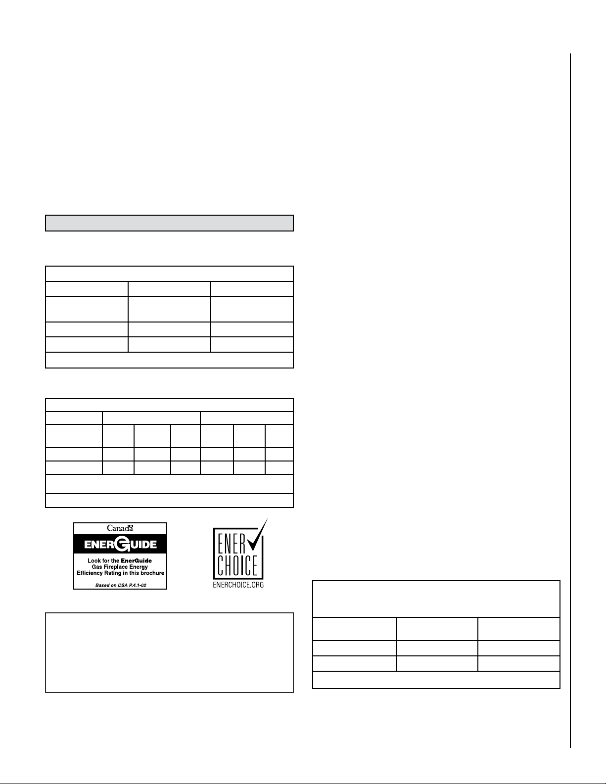
These appliances comply with National Safety Standards and are tested
and listed by OMNI-Test Laboratories Inc.; Portland, Oregon (Report No.
050-F-22-5) to ANSI Z21.88-2005/CSA 2.33-2005, and CGA 2.17-M91 in
both USA and Canada, as Vented Gas Fireplace Heaters and are approved
for installation in bedrooms and manufactured (mobile) homes.
GENERAL INFORMATION
Table 1 shows the BTU input for each model:
Millivolt Models with Manually-Modulated Gas Valves
Natural Gas Propane (LP) Gas
Model Input Rate
(BTU/HR)
SHR33 19,500 to 33,000 19,500 to 33,000
SHR40 24,000-40,000 21,500 to 37,500
Input Rate
(BTU/HR)
Table 1
Table 2 shows efficiencies for the Shoreline™.
Millivolt Valve & Electrical
These appliances use a millivolt type control system consisting of a gas
control valve with regulator (control to adjust for flame appearance and heat
output), a standing pilot burner assembly, a thermopile, thermocouple, a
piezo igniter, and ON/OFF switch. THE GAS BURNER SYSTEM ON THESE
APPLIANCES DO NOT REQUIRE 120 VOLT POWER TO OPERATE. Because
this fireplace insert is operated with a millivolt valve it will burn even
during a power outage.
The Shoreline features a spark igniter (piezo) that allows the appliance's
pilot gas to be lit without the use of matches or batteries. However, the heat
circulation blower motor requires 120 Volts AC (the appliance can be safely
used with the blower turned off). The blower operation is controlled by a
variable speed rheostat.
Fuel
This insert comes from the factory equipped to burn natural gas from 0
to 2,000 feet (610 M) of elevation in the USA and 0 - 4,500 feet (1372
M) in Canada. The insert can be converted to burn LP (liquid propane)
by installing a conversion kit. Only Lennox Hearth Products conversion
kits can be used to convert from NG to LP or LP to NG. Contact your
Lennox Hearth Products dealer for details. An orifice is also supplied to
change the unit from 40,000 BTU’s (NG) or 37,500 BTU’s (LP) to 33,000
BTU’s. This must be done by a qualified service technician if you decide
to change orifices.
The use of other fuels or combination of fuels will degrade the performance
of this system and may be dangerous.
Efficiencies %
Natural Gas Propane
Models P4** Steady
State*
SHR33 60.91 83 60 64.35 83 65
SHR40 62.70 83 63 65.98 83 67
* The Steady State Efficiency numbers based on maximum vent configuration.
** Tested to CSA P.4.1-02 “Testing Method for Measuring Annual Fireplace Efficiency.
AFUE P4** Steady
State*
AFUE
Table 2
These appliances may be installed in an aftermarket permanently
located, manufactured home (USA only) or mobile home, where not
prohibited by local codes.
Cet appareil peut être installé dans un maison préfabriquée (É.-U.
seulement) ou mobile déjà installée à demeure si les réglements
locaux le permettent.
Orifice Size/Altitude Adjustment
These appliances are tested and approved for installations at elevations
of 0 to 2,000 feet (610 M) in the USA and 0 to 4,500 feet (0-1372 M) in
Canada using the factory installed orifice shown in Table 3. At higher
elevations the BTU input must be de-rated by 4% for every 1,000 feet
(305 M) to maintain the proper ratio of gas to air. Contact your local gas
supplier for deration requirements for your area.
Deration - At higher elevations, the amount of BTU fuel value delivered
must be reduced by either using gas that has been derated by the gas
company or by changing the burner orifice to a smaller size as regulated
by the local authorities having jurisdiction and by the (USA) National
Fuel Gas Code NFPA 54 / ANSI Z223.1 - latest edition or, in Canada,
the CAN/CSA B149.1 - latest edition. If it is determined that a smaller
burner orifice is needed, contact your Lennox Hearth Products dealer to
purchase the orifice.
Burner Orifice Sizes
USA - Elevation 0-2000 feet ( 0-610 meters)
Canada - Elevation 0-4500 feet ( 0-1372 meters)
Model
SHR33 #36 (0.1065”) #51 (0.067”)
SHR40 1/8” (0.125”) #49 (.073”)
Natural Gas
drill size (inches) *
Propane
drill size (inches) *
Table 3 * Standard size installed at factory
NOTE: DIAGRAMS AND ILLUSTRATIONS ARE NOT TO SCALE
5
Page 6
SMOKE DETECTORS
Since there are always several potential sources of fire in any home, we
recommend installing smoke detectors. If possible, install the smoke
detector in a hallway adjacent to the room (to reduce the possibility of
occasional false activation from the heat produced by the appliance). If
your local code requires a smoke detector be installed within the same
room, you must follow the requirements of your local code. Check with
your local building department for requirements in your area.
CODES AND APPROVALS
Local, State and National Codes - These appliances must conform with
all local, state, and national installation codes. In the absence of local
and state codes, installation must comply with the current National Fuel
Gas Code, ANSI Z223.1, also known as NFPA 54 (In Canada, the current
CAN/CSA B149.1 installation code). Electrical wiring must comply with
the National Electrical Code ANSI/ NFPA 70 - latest edition. In Canada, the
current CSA C22-1 Canadian Electrical Code - latest edition. Refer to the
National Fuel Gas Code and local zoning and code authorities for details
on installation requirements. These appliances must be vented directly
to the outside in accordance with the current edition of the National Fuel
Gas Code (NFPA 54 in U.S.A and CAN/CSA B149.1 in Canada) and must
never be attached to a chimney serving a separate solid fuel burning
appliance.
Listing and Safety Standards - Gas appliances must be tested and certified by a nationally recognized testing and certification laboratory to ANSI
(American National Standard Institute) gas appliance safety standards.
This insert has been tested and certified by OMNI -Test Laboratories to
ANSI Z21.88/CSA 2.33 “Vented Gas Fireplace Heaters and CGA 2.17M91 “Gas-Fired Appliances for Use at High Altitudes” and UL 307B Gas
Burning Heating Appliances for Manufactured (Mobile) Homes in both
USA and Canada. These appliances have been certified for use with
either natural gas or propane and are approved for installation in sitting
rooms and/or bedrooms. This appliance is only for use with the type of
gas indicated on the rating plate (and is not for use with solid fuels).
This appliance is not convertible for use with other gases, unless a
certified kit is used.
Cet appareil doit être utilisé uniquement avec les types de gaz indiqués
sur la plaque signalétique. Ne pas l'utiliser avec d'autres gaz sauf si
un kit de conversion certifié est installé.
Manufactured Home Installations - These appliances must conform
to the Manufactured Home Construction and Safety Standard, Title 24
CFR, Part 3280 (in Canada CAN/CSA Z240 MH) (in Canada CAN/CSA
Z240 MH), or when such a standard is not applicable, the Standard
for Manufactured Home Installations, ANSI A225.1 - latest edition for
manufactured (mobile) home installations and the current Standard for
Fire Safety Criteria for Manufactured Home Installations, Sites and Communities, ANSI/NFPA 501A.
Fireplace Standards - These heaters are designed to be installed into
an existing masonry fireplace (built to UBC 37 or ULC S628 standards)
or factory built solid fuel, wood, burning fireplace (listed to UL 127 or
ULC S610) only. All exhaust gases must be vented outside the structure.
Combustion air is drawn from outside the structure.
Questions To Ask Local Building Official
These appliances must be installed per manufacturers’ instructions.
Installations must conform to appropriate local codes and applicable
state and federal requirements. Familiarity with these requirements
before installation is essential. Some important considerations to
discuss with local building officials include:
1. Applicable codes (i.e. Uniform Mechanical Code, State or Regional
Gas Codes, National Fuel Gas Code).
2. Local amendments
3. Recognized testing lab: OMNI-Test Laboratories Inc.; Portland,
Oregon
4. Is a permit required - cost?
5. In some states or municipalities, a licensed gas fitter or plumber may
be required to install these appliances. Check with your local building official for requirements in your area (i.e. Is a license required for
installation of gas supply line)?
6. Maximum amount of gas pipe without a pressure test - type of test
required?
7. Are below grade penetrations of the gas line allowed?
8. Is concealed gas piping allowed?
9. Specific requirements of concealed fittings?
10. Is rigid pipe to appliance required?
11. Allowed piping materials?
12. Shut-off valve required within 4 feet of the firebox?
13. May the shut-off valve be concealed?
14. Rooms where the installation is not allowed?
6
NOTE: DIAGRAMS AND ILLUSTRATIONS ARE NOT TO SCALE
Page 7

NEW YORK CITY, NEW YORK (MEA)
COMMONWEALTH OF MASSACHUSETTS REQUIREMENTS
(NYC MEA Approval #138-07-E)
Installation of these appliances are approved for installation in New York
City in the US state of New York.
(Massachusetts Approval #G3-0508-369)
These appliances are approved for installation in the US state of Massachusetts if the following additional requirements are met:
•
Install this appliance in accordance with Massachusetts Rules and
Regulations 248 C.M.R.
• Installation and repair must be done by a plumber or gas fitter licensed
in the Commonwealth of Massachusetts.
• The flexible gas line connector used shall not exceed 36 inches (92
centimeters) in length.
• The individual manual shut-off must be a T-handle type valve.
Massachusetts Horizontal Vent Requirements
In the Commonwealth of Massachusetts, horizontal terminations installed
less than seven (7) feet above the finished grade must comply with the
following additional requirements:
• A hard wired carbon monoxide detector with an alarm and battery
back-up must be installed on the floor level where the gas fireplace
is installed. The carbon monoxide detector must comply with NFPA
720, be ANSI/UL 2034 listed and be ISA certified.
• A metal or plastic identification plate must be permanently mounted to
the exterior of the building at a minimum height of eight (8) feet above
grade and be directly in line with the horizontal termination. The sign
must read, in print size no less than one-half (1/2) inch in size, GAS
VENT DIRECTLY BELOW. KEEP CLEAR OF ALL OBSTRUCTIONS.
NOTE: DIAGRAMS AND ILLUSTRATIONS ARE NOT TO SCALE
7
Page 8
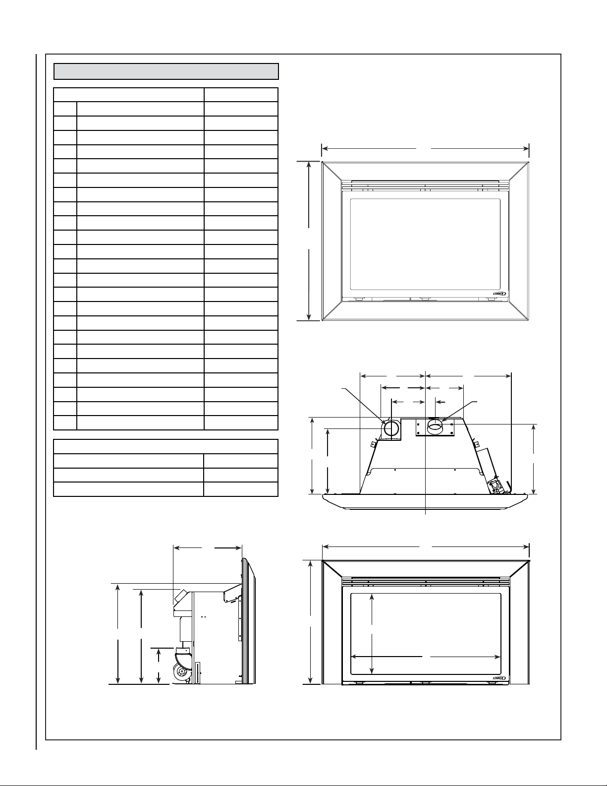
SPECIFICATIONS: Shoreline™
K
L
M
J
N
R
S
O
P
Q
3-Sided Surround Kit
4-Sided Surround Kit
Center
A
B
C
D
E
F
G
H
I
FLUE
Ø 2-7/8
AIR INTAKE
Ø 2-7/8
Insert Dimensions Inches (millimeters)
A
Left front of unit to center line 13-1/8 (333)
B
Right front of unit to center line 17-1/4 (438)
C
Left rear of unit to center line 9 (229)
D
Right Rear Of Unit To Center Line 7-5/8 (194)
E
Center Of Air Intake To Center Line 6-3/4 (172)
F
Center Of Flue To Center Line 2 (51)
G
Insert Depth Into Fireplace 15-3/8 (391)
H
Air Intake Center From Front 12-7/8 (327)
I
Flue Center From Front Of Unit 14 (356)
J
Front Of Unit To Back Of Flue Collar 15-1/8 (384)
K
Unit Height At Front 22-3/8 (568)
L
Base Of Unit To Top Of Flue Collar 21 (533)
M
Base Of Unit To Intake Collar 7-7/8 (200)
N
O.D. Width, Small, 3-pc Flange 36-5/8 (930)
N
O.D. Width, Large, 3-pc Flange 41 (1041)
O
O.D. Height, Small, 3-pc Flange 25-7/8 (657)
O
O.D. Height, Large, 3-pc Flange 28 (711)
P
O.D. Width, Small, 4-pc Flange 36-5/8 (930)
P
O.D. Width, Large, 4-pc Flange 41 (1041)
Q
O.D. Height, Small, 4-pc Flange 29-3/16 (741)
Q
O.D. Height, Large, 4-pc Flange 33-1/2 (851)
R Glass Viewing Height 16-7/8 (429)
S Glass Viewing Width 26-5/8 (676)
Note: Due to Lennox’ ongoing commitment to quality , all specifications,
ratings and dimensions are subject to change without notice.
Front View
Rear Insert Dimensions - Inches (millimeters)
Rear width of unit 16-5/8 (422)
Front Width of unit 30-3/8 (772)
Depth of unit (excluding Surround Kit) 15-3/8 (391)
Top View
Side View
Front View
Figure 1
8
NOTE: DIAGRAMS AND ILLUSTRATIONS ARE NOT TO SCALE
Page 9
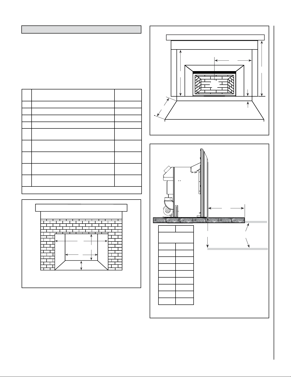
MINIMUM CLEARANCES TO COMBUSTIBLES
E
F
G
H
I
C
L
A
B
C
D
These appliances can be installed in most fireplace configurations. If
installed close to an adjacent wall, ensure that the minimum clearances
to combustible surfaces are maintained. A local building inspector
should review your plans prior to installation.
Refer to Figures 2 through 4 for clearances to combustibles. Minimum
clearances include any projections such as shelves, window sills, mantels,
spacers/standoffs or surfaces to combustible construction etc. above the
appliance. Paint or lacquer used to finish the mantel must be heat resistant
in order to avoid discoloration.
Mantel - 12” Depth
Combustibles Trim or Mantel Depth of 8” or Less
Minimum Fireplace Dimensions
and Minimum Clearances
A Minimum front opening required 36 (914)
B Minimum height required 21-1/2 (546)
C Minimum rear width required 19-1/2 (495)
D Minimum fireplace depth required 16 (406)
E Clearance needed from bottom of insert to com-
bustibles or 8” mantel
F Clearance required from center of glass to com-
bustible material
G Minimum inches of hearth protection needed from
front of unit
H Vertical clearance needed under the bottom of the
insert for NO hearth protection
I Clearance needed from bottom of insert to 12”
mantel
Table 4
Refer to Figures 2 through 4
Refer to Table 4
Figure 2 - Existing Fireplace Minimum Dimensions
Hearth / Floor Protection Requirements
The hearth and/or floor protection must be a thermally rated hearth/floor
protector meeting or exceeding a thermal rating of k = .84 (or lower) or
r= 1.19 (or higher) with a listed thickness of 1" minimum. If an hearth
extension is used, check with the manufacturer for the listed thermal rating
of the hearth extension to ensure it meets the thermal requirements of k
= .84, r= 1.19, listed thickness 1". If a custom hearth or floor protection
is planned, see NFI (National Fireplace Institute) certification manuals
showing methods for calculating minimum thicknesses and approved
fireplace hearth/floor protection materials.
NOTE: DIAGRAMS AND ILLUSTRATIONS ARE NOT TO SCALE
Inches
(millimeters)
35 (889)
30 (762)
12 (305)
8 (203)
38 (965)
Hearth Protection
Figure 3 - Minimum Clearances
Fireplace Firebox
Insert
G H
H dimension deter-
mines G minimum
0” 8”
1-1/2” 7”
3” 6”
4-1/2” 5”
6” 4”
7-1/2” 3”
9” 2”
10-1/2” 1”
12” 0”
Examples:
Hearths that are level with the base
of the insert require 12” minimum of
forward hearth protection.
Hearths that are elevated 8” minimum
above combustible floor require 0” of
forward hearth protection.
Figure 4 - Hearth Protection
Hearth Protection
H
Refer to Table 4
G
Combustible Floor
9
Page 10
INSTALLATION
CAUTIONS
Fireplace Requirements
These heaters are designed to be installed into an existing masonry
fireplace (built to UBC 37 or ULC S628 standards) or factory built solid
fuel, wood burning fireplace (listed to UL 127 or ULC S610) only. All
exhaust gases must be vented outside the structure. Combustion air
is drawn from outside the structure. When installing in a factory built
fireplace, the fireplace grate must be removed and the damper must be
removed or secured open.
The insert is designed to fit into a fireplace with a minimum firebox
height of 21-1/2 inches (546 mm). To facilitate this the hood will need to
be removed and discarded (Note: the screws should be replaced in the
insert body). The air intake on the Shoreline™ is removable for easier
installation.
If the factory-built fireplace has no gas access hole(s) provided, an access
hole of 1-1/2 inches (38 mm) or less may be drilled through the lower
sides or bottom of the firebox in a proper workmanship like manner. This
access hole must be plugged with a non-combustible insulation after the
gas supply line has been installed. The installer must mechanically attach
the marking supplied with the gas fireplace insert to the inside of the firebox
of the fireplace into which the gas fireplace insert is installed.
Si le foyer préfabriqué ne comporte pas d’orifices d’amenée du gaz, un
orifice d’au plus 37,5 mm (1,5 po) peut être pratiqué, selon les règles
de l’art, dans la partie inférieure des parois ou au fond de la chambre de
combustion. Cet orifice doit être obturé au moyen d’isolant incombustible
une fois la conduite de gaz en place.
IMPORTANT: When installing these appliances into a factory built fireplace
or heat-form, the air flow within and around the fireplace shall not be
altered by the installation of the insert (i.e. DO NOT BLOCK louvers or
cooling air inlet or outlet ports, circulating air chambers in a steel fireplace
liner or metal heat circulator).
WARNING
THIS FIREPLACE HAS BEEN ALTERED TO
ACCOMMODATE A FIREPLACE INSERT AND
SHOULD BE INSPECTED BY A QUALIFIED
PERSON PRIOR TO RE-USE AS A
CONVENTIONAL FIREPLACE.
• Trim panels or surrounds must not seal ventilation openings in the existing fireplace that the
appliance is installed in.
• The fireplace in which this gas insert is to be
installed must be thoroughly cleaned if it has
been used to burn wood or synthetic logs. Have
the chimney and all inside surfaces of the fireplace brushed and vacuumed so that no soot,
embers, or loose combustion deposits can be
drawn into the heat circulation blower and blown
into the living area.
• If any portion of the chimney system shows signs
of structural or mechanical weaknesses, such
as: cracks, leaky joints, corroded or warped
surfaces, the faulty portion must be repaired
or replaced prior to installing this appliance.
• The factory built firebox must accept the insert
without modification other than removing bolted
or screwed together pieces such as baffles /
smoke shelf / deflectors, ash lips, glass door,
screen or door tracks, log grates, refractory or
masonry lining and damper assemblies. Any
fireplace component, which is removed, must be
retained so they can be reinstalled to restore the
fireplace to its original operating condition. The
removal of any part must not alter the integrity
of the outer shell of the pre-engineered fireplace
cabinet in any way. Any parts removed must be
replaceable. If any components are removed
from (or altered) from the existing fireplace, a
Warning Label (see Figure 5) must be affixed
inside the fireplace firebox, so that it shall be
visible upon removal of the fireplace insert. Note:
RTV high temperature silicone is an approved
adhesive to affix the label.
10
Figure 5 - Fireplace Warning Label
NOTE: DIAGRAMS AND ILLUSTRATIONS ARE NOT TO SCALE
Page 11
Venting Requirements
Approved Vent Systems:
Lennox Hearth Products Co-linear Chimney Liner Kit Recommended:
• The Flex Kit, Cat. No. H0909 includes one 35 feet flex liner and four
gear clamps.
• The Termination Kit, Cat. No. TKDVI includes the termination cap with two
co-linear collars for 3 inches (76 mm) flex attachments and flashing.
• The Flex and Termination Kit, Cat. No. DV3FK35 includes two flex liners,
termination cap and four gear clamps.
Secure Vent™ Co-Linear Chimney Liner Kit Recommended:
• Direct-Vent Vertical Termination Kit (includes Vertical Termination
Cap gas/Connector, Flashing, Qty 2 of 25 feet (7.6 M) length of 3 inches
(76 mm) Aluminum Flex, Clamps and Sealant) #DV3FK25
• Direct-Vent Vertical Termination Kit (includes Vertical Termination Cap/
Connector, Flashing, Qty 2 of 35 feet length of 3 inches Aluminum
Flex, Clamps and Sealant) #DV3FK35
Standard Simpson Dura-vent Co-linear Chimney Liner Kit recommended:
• Direct-Vent Vertical Termination Cap #991
• Liner Termination Kit
(includes termination connector and flashing) #923GK
• 3" x 35 feet (76 mm x .91 M) Alum Flex #2280
Selkirk/Metalbestos Direct-Temp Co-Linear Chimney Liner Kit recom-
mended
• Direct-Vent Vertical Termination Cap #4DT-VC
• Liner Termination Kit
(includes termination connector and flashing) #4DT-CTB
• 3” x 35’ (76 mm x .91 M) Aluminum Flex #AF3-35L
Amerivent Direct Co-Linear Chimney Liner Kit recommended
• Direct-Vent Vertical Termination Cap #4DVC
• Co-Linear Adaptor #4DCAT33
• Flashing #4DF or #5DF
• 3” x 35’ Aluminum Flex #3AFL-35
NOTE: Terminating the air intake liner as shown here may not be
allowed by some local codes. Check with the authority having jurisdiction for your area.
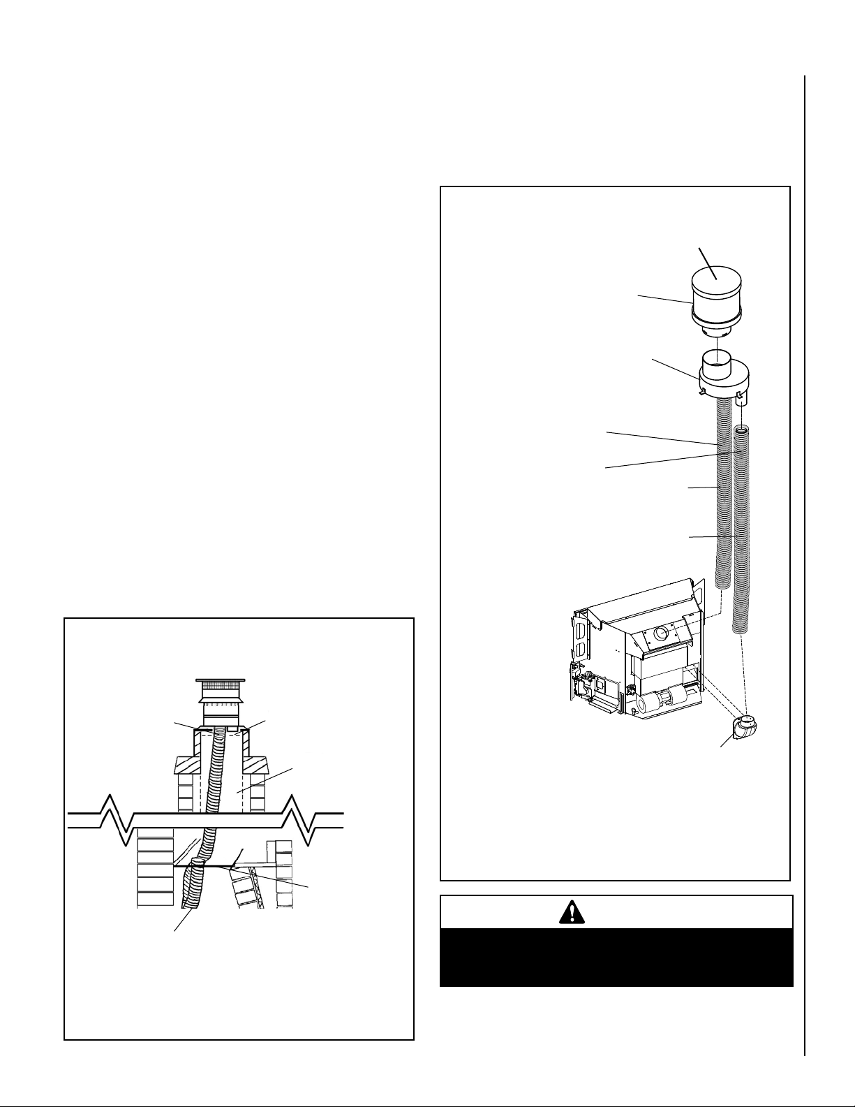
Positive Flue Connection
Masonry and Factory Built Fireplaces
A qualified installer should evaluate the existing fireplace to determine
the best method for achieving a positive flue connection between the vent
and intake liners and the chimney.
The existing fireplace chimneys may take
various contours which the flexible liners will
accommodate. However, keep the flexible liner
as STRAIGHT as possible, avoid unnecessary
bending.
Vertical Cap
Termination
Connector
The standard cap
in Termination Kit,
TKDVI, is a high
wind cap
Liner Requirements:
Use 3" (76 mm) diameter listed gas
vent liner (UL1777 ONLY) for the
EXHAUST
Use 3" (76 mm) diameter listed
liner (UL 181 or UL1777) for the
AIR INTAKE.
Vertical Height Min. = 10 ft. (3.05 M)
Vertical height Max. = 35 ft. (10.67 M)
The flexible vent pipe
must NOT be allowed to
sag behind insert or in
fireplace flue.
Exhaust
Intake
Exhaust 3" (75mm) UL
1777. A full length liner
is required from the
exhaust outlet on appliance to center collar of
termination cap.
Exhaust
Air Inlet
Air Inlet Liner (for combustion air) When
terminating the air inlet liner at this point, a
positive flue connection is required (to ensure
combustion air is drawn down the chimney
only).
The outside air inlet does not
require a full reline (if intake
liner is terminated in chimney
and a positive flue connection
is achieved as specified).
Air Inlet
Masonry and Factory Built Fireplaces
Figure 6a - Terminating Air Inlet in Chimney
Existing Fireplace Flue
(chimney)
Make sure that both liners will pass through existing damper area. Remove
or lock damper to allow the passage of the flexible liners. If the damper
will not allow the passage of both liners, DO NOT PROCEED FURTHER.
(If fireplace is masonry) Consult a local mason for removal of the damper
without risk of structural damage or leakage (if the fireplace is factory
built) The appliance may NOT be installed into the fireplace.
Figure 6b
Positive Flue Connection (sealing
fireplace throat
using a noncombustible seal-off plate
or insulation).
Do not substitute the heat-rated flex liner (UL1777) for the
exhaust with any other type liner or a fire may result causing property damage, personal injury or loss of life.
NOTE: DIAGRAMS AND ILLUSTRATIONS ARE NOT TO SCALE
Combustion Air Intake
WARNING
11
Page 12

Vertical Venting
� � � � � � � � � � � � � � � � � �
� � � � � � � � � � � � � � � � � �
� � � � � � � � � � � � � � � � � �
� � � � � � � � � � � � � � � � � �
� � � � � � � � � � � � � � � � � �
� � � � � � � � � � � � � � � � � �
� � � � � � � � � � � � � � � � � �
� � � � � � � � � � � � � � � � � �
The combustion air intake pipe can be connected to the termination cap
(see Figure 6b) or it can terminate inside the chimney (see Figure 6a).
If combustion air intake pipe is terminated inside the chimney and not
connected to the actual termination cap the bottom opening of the chimney (chimney throat) must be sealed around the vent pipes. Use a non
combustible seal-off plate (i.e. 22 gage sheet steel) or unfaced fiberglass
insulation (8 lb per square foot density minimum) to seal around the vent
pipes. Whichever “seal off” method is used must effectively seal the area
to prevent room air passage to the chimney of the fireplace. The insulation
may give off an odor during the first hour of operation.
NOTES:
The minimum vertical rise (exhaust vent) is 10 feet (3.05 M) and the
maximum vertical rise is 35 feet (10.67 M). These dimensions are
measured from the flue collar of the unit to the end of the vent pipe,
The fireplace and fireplace chimney must be clean and in good working
order and constructed of non-combustible materials. Inspect chimney
clean-outs for proper fit and seal.
See Table 5 for the minimum vertical termination height requirements.
Vertical Termination Height Minimum
(Factory Built and Masonry Fireplaces)
The vent/air intake termination clearances above the high side of an
angled roof is as follows:
FRONT
LEVELING
LEGS
Front leveling legs
See Detail A
Feet (meters)
8 (2.4)
7 (2.1)
6 (1.8)
5 (1.5)
4 (1.2)
3 (0.9)
2 (0.6)
1 (0.3)
0 (0.0)
6/12
Roof Pitch
8/12
10/12
12/12
14/12
16/12
Table 5
2/12
4/12
Insert Leveling
At each front and rear corner of the insert is an adjustable leg provided
to level the insert should the hearth of the fireplace be uneven. To adjust
the legs in the rear, loosen the two 5/32” allen head screws, move the leg
to the desired height, and then tighten the screws. Repeat these steps
for each adjusting leg. To adjust the legs in the front use a 9/16” open
end wrench. See Figures 7 and 8.
NOTE: The rear leveling legs on each side of the gas fireplace insert unit
have 13/64” holes located in them for the purpose of fastening the rear
of the unit down in the fireplace (masonry or factory built fireplace).
Figure 7
Right front leveling leg. Use open end 9/16”
wrench to adjust height up or down
Detail A
See Detail B
REAR
LEVELING
LEGS
12
Use 5/32 allen wrench to loosen and adjust
bracket up or down, tighten when at right height
Detail B
Figure 8
Page 13
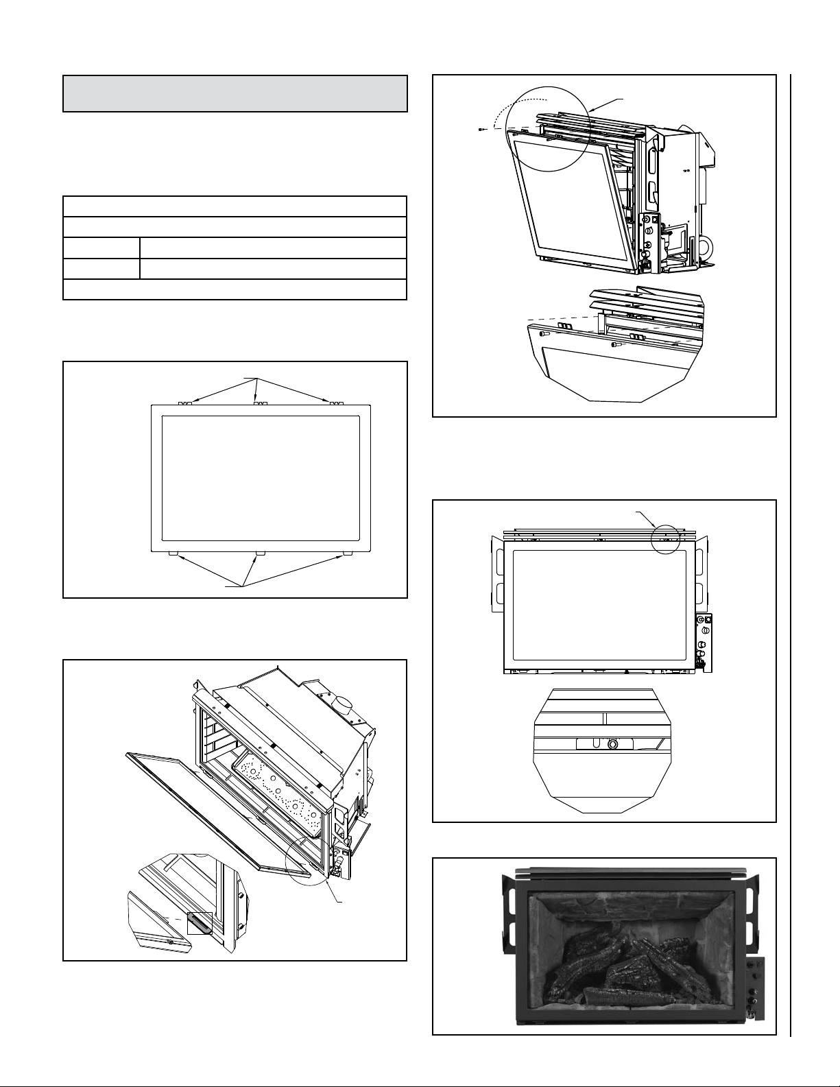
SHORELINE™ DOOR ASSEMBLY INSTALLATION OR REMOVAL
INSTRUCTIONS
Tools Needed: 5/32” Allen Wrench or T-Handle
Cat. No. Description
H5746 Shoreline Door Assembly
(Figure 9)
Shoreline Door Kit - Packaging List
Models SHR33 & SHR40
Quantity Description
1
Shoreline Door Assembly
Table 6 - (refer to Figure 9)
Note: The Shoreline insert comes with the door already on the unit.
Just reverse the steps here to remove the door to access the burner
area.
Upper Latch Tabs
See Detail E
Figure 11
Detail E
3. Using the 5/32” Allen Wrench or T-Handle insert the three 10-24 screws
with washers into the three locations on the upper latch assembly. You
can then tighten the screws down by turning the wrench or T-Handle
clockwise (SNUG ONLY-DO NOT OVERTIGHTEN). See Figure 12.
Figure 9
Bottom Tabs
1. Locate the three bottom tabs on the bottom of the door. These tabs
on the bottom of the door will insert in the slots along the bottom of
the insert. See Figure 10.
See Detail C
See Detail B
Figure 12
Figure 13 shows the insert with the door in place.
4.
Detail B
Figure 10
Detail C
2. Drop the door into these three slots on the bottom of the insert as
shown in Figure 11. Once this is done you can then rotate the door
up to seal against the firebox front.
NOTE: DIAGRAMS AND ILLUSTRATIONS ARE NOT TO SCALE
Figure 13
13
Page 14

SHORELINE™ REFRACTORY BRICK INSTALLATION INSTRUCTIONS
Tools Needed: No tools are needed
Cat. No. Model Description
H7987 SHR-BRK-STD Brick Panel Set, Tan
H7988 SHR-BRK-RED Brick Panel Set, Red
H7989 SHR-BRK-ARCHSTONE Brick Panel Set, Architectural (shown)
2. Next place the rear panel (B). It will set on the bracket mounted to the
blower mounting plate on the back of the firebox. See Figure 16.
Refractory Brick Panel Kits - Packaging List
Quantity Description
1 Front Bottom Panel (A)
1 Rear Panel (B)
1 Left Side Panel (C)
1 Right Side Panel (D)
1 Top Panel (E)
Table 7 - (refer to Figure 14)
IMPORTANT NOTE: A refractory brick panel kit is required for proper
operation (sold separately). Never operate this appliance without
all the refractory brick panels properly installed.
Models SHR33 & SHR40
E
C
D
B
Figure 16
3. Position and slide the side panels against the rear panel. Make sure
panels are behind brackets to hold them in at the top. The side panels
will hold the rear brick panel against the back of the firebox. See Figure
17.
B
Figure 14
A
CAUTION
Before you install the refractory brick panels and log
set, the insert should be installed in the fireplace, the
venting attached, the gas line connected and tested
for leaks and the initial burner operation checked.
To Install Panels:
1. Start with the front bottom panel A. Set the front bottom panel in
place with detail side facing up as shown. See Figure 15.
A
C D
Figure 17
4. Slide the top panel in place with the detailed side down. Make sure
panel is positioned all way back and resting on side panels. Top panel
should be flush in front with the side panels. See Figure 18.
E
Figure 18
14
Figure 15
NOTE: DIAGRAMS AND ILLUSTRATIONS ARE NOT TO SCALE
Page 15

SHORELINE™ LOG SET INSTALLATION INSTRUCTIONS
CAUTIONS
Tools Needed: No tools are needed
Cat. No. Description
H5747 5-Piece Ceramic Log Set
Log Set - Packaging List
Models SHR33 & SHR40
Quantity Description
1 Rear Log (A)
1 Center Log (B)
1 Left Log (C)
1 Right Log (D)
1 Front Log (E)
1 Bag of Glowing Embers (F)
1 Bag of Decorative Lava Rock (G)
Table 8 - (refer to Figure 19)
G
A
• If logs are not installed according to the log
installation instructions, flame impingement
and improper combustion could occur and result
in soot and/or excessive production of carbon
monoxide (CO), a colorless, orderless, toxic
gas.
• The size and position of the log set is critical
to achieve a safe, reliable and attractive flame
pattern. Any attempt to use a different log set
in the fireplace will void the warranty and will
result in incomplete combustion, sooting, and
poor flame quality.
To Install Log Set:
1. Open the box and carefully remove and identify the different items.
Start with the rear log (A). Set it down on the log supports located
on the left rear of firebox. See Figure 21.
Log supports
F
Figure 19
B
C
A
D
E
Figure 21
A
C
B
D
E
Figure 20
NOTE: DIAGRAMS AND ILLUSTRATIONS ARE NOT TO SCALE
15
Page 16

2. Separate the glowing embers (F) into quarter size pieces and place
along ports on burner pan. DO NOT cover burner secondary holes
on burner pan. The pattern for the glowing embers should be similar
to what is shown in Figure 22.
F
Glowing Embers
Separate into Quarter
Size (separate) Pieces
4. Place left log (C) on pin in back. Push log against left side of refractory
in front. See Figure 24.
pin
C
Figure 24
5. Locate groove in center log (B), and place the top of the right log
(D) in groove with the bottom end of the log resting against the right
refractory panel. See Figure 25.
Groove for log (D)
Bag of Glowing
Embers (rockwool)
Figure 22
3. Place center log (B) on supports towards bottom left and top right of
log (B). See Figure 23.
B
Figure 23
D
Figure 25
6. Place the front log (E) as shown in
ports are covered. Place the decorative lava rock around logs as
desired, again making sure there are no ports or holes covered.
Figure 26, making sure no burner
16
E
Figure 26
7. Figure 26 shows the complete set of ceramic logs in the correct locations.
NOTE: DIAGRAMS AND ILLUSTRATIONS ARE NOT TO SCALE
Page 17

SHORELINE™ SURROUND ASSEMBLY INSTALLATION
Tools Needed: No tools are needed
One of the following surround kits is required (Purchased separately).
Surround Kits
Models SHR33 & SHR40
Part/Cat. # Description Dimensions
75387 Small 3-sided Flange 36-5/8”W x 25-7/8”H
75385 Small 4-sided Flange 36-5/8”W x 29-3/16”H
75388 Large 3-sided Flange 41”W x 28”H
75386 Large 4-sided Flange 41”W x 33-1/2”H
Table 9
Note: Install surround with insert positioned in the fireplace, but a
few inches in front of its final location.
Detail A
Detail B
Figure 27
To Install Surround Panels:
1. Hang the surround on hooks attached to insert (labeled A and B).
Make sure the surround is seated firmly on the hooks. See Figures
28 and 29.
Hook A
See Detail A
See Detail B
Figure 29
2 Slide the insert into its final location in the fireplace. In case of uneven
wall surface open the right surround access door and make any
adjustments needed to ensure there is enough clearance to open the
access door (see Page 18).
Figure 28
Hook B
Figure 30
Important Note: The trim panels or surrounds must not seal ventilation
openings on the appliance.
NOTE: DIAGRAMS AND ILLUSTRATIONS ARE NOT TO SCALE
17
Page 18

SURROUND BALL SCREW MOUNT ADJUSTMENT
Tools Needed:
7/16” wrench
Adjustment Procedure:
Step 1 Open the surround access door. Inspect the tension or lack of
tension while opening the door to determine if it should open
easier or tighter.
Step 2 With access door open you will see the ball screw and jam nut
on the surround backing plate near the top surround piece as
seen in picture A. Using a 7/16” wrench, loosen the jam nut on
the ball screw as shown in Picture B.
Step 3 Once this jam nut is loose you can then adjust the ball screw
for more or less tension using your fingers as seen in Picture
C. Turning the ball screw counter-clockwise, as you are looking at it, will give you less tension and turning the ball screw
clockwise will give you more tension when opening and closing
the surround access door. Picture D is showing the ball screw
adjusted down for additional tension.
Step 4 You can then test close the surround access door to ensure it
has proper tension. Readjust if needed.
Step 5 Once the proper tension is achieved, hold the ball screw with
your fingers, then using a 7/16” wrench tighten the jam nut,
clockwise (SNUG ONLY, DO NOT OVERTIGHTEN).
Adjust Ball Screw
Ball screw shown adjusted
down for additional tension
C
D
Loosen jam nut
on ball screw.
A
Ball Screw
Jam Nut
E
Jam Nut
B
Once proper tension is achieved, tighten the jam nut.
18
NOTE: DIAGRAMS AND ILLUSTRATIONS ARE NOT TO SCALE
Page 19

GAS LINE INSTALLATION
Tables 10 and 11 show the units' gas pressure requirements for
these appliances.
We recommend that a qualified individual such as a plumber or gas fitter be
used to correctly size and route the gas supply line to the appliance. Installing
a gas supply line from the fuel supply to the appliance involves numerous
considerations of materials, protection, sizing, locations, controls, pressure,
sediment, and more. Certainly no one unfamiliar and unqualified should attempt
sizing or installing gas piping. Never use galvanized or plastic pipe.
The gas supply line should be plumbed from the fuel source to the area
where the appliance is to be installed per requirements outlined in NFPA
54 - latest edition (USA) or CAN/CSA B149.1 - latest edition (Canada)
and per local codes.
The insert comes with an 8 inch (203 mm) nipple attached to the supply
side of the gas valve. After connecting the gas line, all joints in the line
and connections at the valve should be checked for leaks using a gas leak
test solution before final positioning of the unit. Conduct a gas leakage
test of the appliance piping and control system downstream of the shutoff
valve in the supply line to the appliance.
Gas Pressure Requirements
It is important to check the gas pressure during the initial installation
of the insert and ensure there are no operating problems. This insert
will not function properly unless the required gas pressure is supplied.
Two pressure taps are provided on the insert's valve to check gas pressures (see Figure 37 on Page 25). The taps are located to the left of the
on/off/pilot knob. The top tap is the inlet (supply) pressure side. To check
inlet pressure (with the fireplace insert burning), insert a small regular
screwdriver into the tap and turn a half turn counterclockwise. Cover the
tap with the line from a manometer and check the pressure. Close the tap
gently but securely after completing the check. The manifold (outlet) tap
is below the inlet tap. To check manifold pressure (with the insert burning
at the high burn setting) insert a small phillips screwdriver into the tap
and turn a half turn counterclockwise. Cover the tap with the line from
the manometer and check the pressure. Again, close the tap gently but
securely after completing the check. Check the taps for gas leaks with a
gas leak test solution and retighten if necessary.
Inlet Gas Supply Pressure
Fuel # Minimum Maximum Desired
Natural
Gas
Propane
5" WC/po. C.E
(1.25 kPa)
10.5" WC/po. C.E
(2.61 kPa)
10.5" WC/po. C.E
(2.61 kPa)
13.0" WC/po. C.E
(3.23 kPa)
7" WC/po. C.E
(1.74 kPa)
11" WC/po. C.E
(2.74 kPa)
Table 10
Manifold Gas Supply Pressure
Fuel # Low High
Natural Gas
Propane
(Lo) 1.3" WC/po. C.E
(.32 kPa)
(Lo) 5.4" WC/po. C.E
(1.35 kPa)
(Hi) 3.5" WC/po. C.E
(.87 kPa)
(Hi) 10.0" WC/po. C.E
(2.49 kPa)
Table 11
LP and Natural Gas Supplies
Your Shoreline™ can be operated with either natural gas or liquid
propane (LP). It is shipped from the factory for use with only natural
gas. The fireplace insert must always be operated with the same gas as
specified on the label unless converted by a qualified service technician
as per this manual.
Also check the orifice size on the label located below the Shoreline insert.
It must be the correct size for the fuel and altitude.
If the pressure is too low, make sure the gas supply line is large enough,
the supply regulator is properly adjusted, and the total gas load for the
residence does not exceed the amount supplied.
IMPORTANT NOTE: If propane is used, be aware that if the tank size is too
small (i.e. under 100-lbs, if this is the only gas appliance in the dwelling.
Ref. NPFA 58), there may be loss of pressure, resulting in insufficient fuel
delivery (which can result in sooting or other malfunctions). Any damage
resulting from an improper installation, such as this, is not covered under
the limited warranty.
Propane tanks are at pressures that will cause damage to valve components. Verify that the tanks have step down regulators to reduce the
pressure to safe levels.
These appliances must be isolated from the gas supply piping system
(by closing their individual manual shut-off valve) during any pressure
testing of the gas supply piping system at test pressures equal to or
less than 1/2 psig (3.5 kPa).
These appliances and their individual shut-off valves must be disconnected from the gas supply piping system during any pressure testing
of that system at pressures greater than 1/2 psig (3.5 kPa).
NOTE: DIAGRAMS AND ILLUSTRATIONS ARE NOT TO SCALE
19
Page 20

La chimenea caliente causará quemaduras graves
Nunca permita que los niños
toquen el vidrio ni otras
partes de la chimenea
ADVERTENCIA
Un foyer chaud peut causer
de graves brûlures
Ne laissez jamais un enfant
toucher à la vitre ou à toutes
autres parties du foyer
A
VE
R
TISSEMENT
Hot Fireplace Will Cause
Severe Burns
Never Allow Children to
Touch Glass or other Fire-
place Parts
WARNING
INSTALLER INSTRUCTIONS - ATTACHING SAFETY IN OPERATION WARNINGS
Hot Fireplace Will Cause
Severe Burns
Never Allow Children to
Touch Glass or other Fireplace Parts
WARNING
It is the installers responsibility to ensure these warnings are properly affixed during installation. These warning labels are a
critical step in informing consumers of safe operation of this appliance.
ATTACHING SAFETY IN OPERATION WARNINGS
It is required that the safety instruction labels furnished with the fireplace be affixed to the operation
and control point of the fireplace. A safety instruction
label must be affixed to the wall switch plate where
the fireplace is turned on and off (See Figure A)
or wall thermostat (See Figure B) and if used on
the remote control handheld transmitter (Figure
C). To properly complete the installation of this
fireplace, locate the multi-lingual adhesive labels
provided with the Care and Operation Instructions
and proceed as follows:
1. Locate the wall switch or wall thermostat that
controls the fireplace (verify the switch operates
the fireplace by turning it on and off). Clean the
wall switch plate or wall thermostat thoroughly
to remove any dust and oils. Affix the label to
the surface of the plate of the wall switch that
controls the fireplace (Figure A) or the wall
thermostat (Figure B). Choose the language
primarily spoken in the home. If unknown, affix
the English language label.
2. If a remote control is used to control the fireplace,
locate the transmitter and clean it thoroughly
to remove any dust and oils. Affix the label to
the surface of handheld transmitter (Figure C).
Choose the language primarily spoken in the
home. If unknown, affix the English language
label.
3. If you are unable to locate the labels, please call
Lennox Hearth Products or your nearest Lennox
Hearth Products dealer to receive additional
safety instruction labels free of charge.
Cat. No. H8024 Replacement Label Kit
LENNOX HEARTH PRODUCTS
1-800-9-LENNOX
Note: English is red text on clear label. French and
Spanish are white text on black label.
APPOSITION DES MISES EN GARDE RELATIVES
À LA SÉCURITÉ D’UTILISATION
Il est impératif que les étiquettes de sécurité fournies
avec le foyer soient collées à côté des dispositifs
de contrôle du foyer. Une étiquette de sécurité doit
être collée sur la plaque de l’interrupteur contrôlant
l’allumage du foyer (voir Figure A) ou sur le thermostat
mural (voir Figure B) et, le cas échéant, sur le boîtier
de la télécommande (Figure C). Pour achever l’instal-
lation correcte de ce foyer, procédez comme suit avec
les étiquettes adhésives en langues étrangères fournies
avec les instructions d’utilisation et d’entretien :
1. Repérez l’interrupteur ou le thermostat mural qui
contrôle le foyer (vérifiez que l’interrupteur
contrôle le fonctionnement du foyer en le faisant
basculer de Marche à Arrêt, et vice-versa). Nettoyez
soigneusement la plaque murale de l’interrupteur
ou le thermostat mural pour éliminer la poussière
et les traces de graisse ou d’huile. Collez l’étiquette
sur la surface de la plaque de l’interrupteur mural
qui contrôle le foyer (Figure A) ou du thermostat
mural (Figure B). Choisissez la langue qui est
principalement parlée dans la résidence du
propriétaire. En cas de doute, collez l’étiquette en
anglais.
2. Si une télécommande est utilisée pour contrôler
le foyer, nettoyez la soigneusement pour éliminer
la poussière et les traces de graisse ou d’huile.
Collez l’étiquette sur le boîtier de la télécommande (Figure C). Choisissez la langue qui est
principalement parlée dans la résidence du propriétaire. En cas de doute, collez l’étiquette en anglais.
3. Si vous ne trouvez pas les étiquettes, veuillez
appeler Lennox Hearth Products ou votre distributeur Lennox Hearth Products local pour recevoir
gratuitement des étiquettes supplémentaires.
Étiquettes de remplacement, n° cat. H8024
LENNOX HEARTH PRODUCTS
1-800-9-LENNOX
Remarque : Le texte anglais est rouge sur un support
transparent. Le texte français et espagnol est blanc
sur un support noir.
COLOCACIóN DE ADVERTENCIAS DE SEGURIDAD
EN OPERACIóN
Se requiere que las etiquetas de instrucciones de
seguridad incluidas con la chimenea se coloquen en
el punto de operación y control de la misma. Se debe
colocar una etiqueta de instrucciones de seguridad
en la placa del interruptor de pared desde el cual se
enciende y se apaga la chimenea (ver la Figura A) o en el
termostato de pared (ver la Figura B) y en el transmisor
de control remoto (Figura C) si se usa. Para completar
correctamente la instalación de esta chimenea,
encuentre las etiquetas adhesivas multilingües incluidas
con las instrucciones de cuidado y operación y haga
lo siguiente:
1. Identifique el interruptor o el termostato de pared
que controla la chimenea (verifique que el interruptor
opera la chimenea encendiéndola y apagándola).
Limpie bien la placa del interruptor o el termostato
de pared para quitar el polvo y aceite. Pegue la
etiqueta en la superficie de la placa del interruptor que
controla la chimenea (Figura A) o en el termostato
de pared (Figura B). Seleccione el idioma que
más se habla en la casa. Si no sabe cuál es, use la
etiqueta en inglés.
2. Si se usa un control remoto para controlar la
chimenea, encuentre el transmisor y límpielo bien
para quitar el polvo y aceite. Pegue la etiqueta en
la superficie del transmisor (Figura C). Seleccione
el idioma que más se habla en la casa. Si no sabe
cuál es, use la etiqueta en inglés.
3. Si no puede encontrar las etiquetas, sírvase llamar
a Lennox Hearth Products o al distribuidor de
Lennox Hearth Products más cercano para recibir
etiquetas de instrucciones de seguridad adicionales
gratuitas.
Juego de etiquetas de repuesto - Nº de cat. H8024
LENNOX HEARTH PRODUCTS
1-800-9-LENNOX
Nota: La etiqueta en inglés es transparente con texto
rojo. Las etiquetas en francés y español son negras
con texto blanco.
Un foyer chaud peut causer
de graves brûlures
Ne laissez jamais un enfant
toucher à la vitre ou à toutes
autres parties du foyer
Figure A
20
DIAGRAMMES DES ÉTIQUETTES DE SÉCURITÉ / DIAGRAMAS DE ETIQUETAS DE SEGURIDAD / SAFETY LABEL DIAGRAMS
AVERTISSEMENT
ADVERTENCIA
La chimenea caliente
causará quemaduras graves
Nunca permita que los niños
toquen el vidrio ni otras
partes de la chimenea
Figure B
NOTE: DIAGRAMS AND ILLUSTRATIONS ARE NOT TO SCALE
Figure C
Page 21

OPERATING INSTRUCTIONS
Pre-Lighting Checklist
Lighting Instructions
STOP! Read the safety information on the front cover of the manual
before proceeding.
Be sure to check these items before the initial lighting of the insert:
_____ The insert gas label corresponds to the gas supply available
- that is "natural gas" for natural gas or "LP gas" for LP gas.
_____ Gas pressure has been checked carefully.
_____ All gas fittings have been checked for leaks.
_____ All clearances to combustibles have been met.
_____ All combustible materials have been removed from the area
in front of the insert.
_____ All vented areas of the insert face are unobstructed.
_____ House is ventilated to clear initial curing odor.
_____ All packaging materials have been removed from the fire
box.
_____ While insert is cool, fingerprints or other marks should be
cleaned from any surfaces with a soft cloth. Marks left on these
surfaces may become etched into the finish if not removed
prior to burning the unit.
_____ Brick panels and log set have been installed.
_____ The glass door is in place and is properly sealed.
CAUTION
Your Shoreline™ gas appliance must always be
operated with glass door in place.
1. Open the right side access door. Ensure the gas supply shut-off cocks are
open and ON/OFF Rocker Switch is “OFF”. If equipped with a thermostat,
set it to the lowest setting.
2. Turn off all electrical power to the appliance.
3. Push in the gas control knob slightly and turn clockwise to “OFF”.
NOTE: The knob cannot be turned from “PILOT” to “OFF” unless the knob
is pushed in slightly. Do not force.
4. Wait five (5) minutes to clear out any gas. If you smell gas, STOP! Follow
instructions on the front cover of this manual. If you do not smell gas
continue.
5. Locate the pilot assembly by looking at the rear center of the burner,
behind the large center log. A blue flame will be seen when the pilot is
-
lit.
6. Turn the gas control knob counterclockwise to the “PILOT” posi
tion.
7. Push the knob all the way in and hold in that position. Immediately light
the pilot by pressing the igniter button several times until pilot is lit.
Continue to hold the knob in for about 30 seconds after the pilot is lit.
Release knob and it will pop back out. Pilot should remain lit. If it goes
out, repeat steps 4-8 holding knob in an additional 15 seconds after pilot
is lit.
• If knob does not pop out when released, stop and immediately call
your service technician or gas supplier.
• If the pilot will not stay lit after several tries, turn the gas control
knob to “OFF” and call your service technician or your gas supplier.
8. After pilot is lit, turn gas control counterclockwise to “ON”. Knob
can only be turned “ON” if the knob has popped out.
9. To turn burner on, turn “ON/OFF” rocker switch to “ON” or set the ther
mostat to the desired temperature above room temperature.
10. Adjust the flame height (and heat output) by turning the flame height
knob clockwise for reduced flame and counterclockwise
for full flame.
11. Set the blower to the desired air flow after it turns on when the appliance
reaches operating temperature.
-
-
21
Page 22

Piezo Igniter
Blower Speed
Control (rheostat)
ON/OFF
Switch
Gas Control Knob
(Pilot / On / Off)
To Turn Off Gas To Appliance
1. Turn off the “ON/OFF” rocker switch and/or thermostat (if installed).
2. Turn off electric power to the appliance if service is to be performed.
3. Turn gas control knob clockwise to “OFF”. Do not force.
This appliance needs fresh air for safe operation and must be installed
so there are provisions for adequate combustion and ventilation air. See
Installation and Operation Manual accompanying appliance.
Figure 31 - Gas Controls
Pilot Hood
Thermopile
Figure 32 - Pilot Assembly
Igniter (electrode)
Pilot Assembly
Flame Height
Control Knob
(Hi/Lo)
Thermocouple
Operation of this appliance when not connected to a properly installed and
maintained venting system can result in carbon monoxide (CO) poisoning and
possible death.
Shutdown Procedure
1. To turn off the burner, switch the rocker switch to “OFF” or adjust the
thermostat to a setting below room temperature (if installed). The
pilot will remain lit for future burner ignition.
For complete shutdown: See “To Turn Off Gas To Appliance” above.
WARNINGS
• Improper installation, adjustment, alteration,
service or maintenance can cause injury or
property damage. For assistance or additional
information, consult a qualified installer, service
agency or your gas supplier.
• Operation of this appliance when not connected
to a properly installed and maintained venting
system can result in carbon monoxide (CO)
poisoning and possible death.
• Carbon monoxide poisoning – early signs of
carbon monoxide poisoning resemble the flu
with headaches, dizziness, or nausea. If you
have these signs, get fresh air at once! Have the
heater inspected by a qualified service technician. Some people are more affected by carbon
monoxide than others. These include pregnant
women, people with heart or lung disease or
anemia, those under the influence of alcohol,
and those at high altitudes.
22
NOTE: DIAGRAMS AND ILLUSTRATIONS ARE NOT TO SCALE
Page 23

Flame Appearance and Sooting
Your Shoreline™ fireplace insert is designed for maximum heating
efficiency. Therefore, upon lighting of the main burner the flames will be
semi-transparent or “bluish.” After 10-20 minutes of operation the logs
will heat up and the flames will become a yellow/orange color. If after
20 minutes the flame stays lowered blue, or if the flame is orange with
evidence of sooting (black tip), the air shutter may require adjustment.
Adjusting the insert to cause the flames to turn orange sooner may result
in poor combustion, sooting, and a hazardous situation. See Figures 33
and 34 showing proper flame appearance.
Sooting is indicated by black puffs developing at the tips of very long
orange flames. Sooting results in black deposits forming on the logs,
appliance inside surfaces and on exterior surfaces adjacent to the vent
termination. Sooting is caused by incomplete combustion in the flames
and lack of combustion air entering the air shutter opening. To achieve
a warm yellow to orange flame that does not soot, the shutter opening
must be adjusted between these two extremes.
Soot at
Flame Tip
Dark Orange
Flame
No Blue Flame
Center
Soot above
Flame Tip
Ports on Pan
Burner Assembly
No Soot at
Flame Tip
Semi-Transparent
Yellow Flame
Blue Flame
Center
CAUTIONS
• Carbon will be produced if the air shutter is
closed too much. Any damage due to carboning
resulting from improperly setting the air shutter
is not covered under the warranty.
• The air shutter control arm and nearby appliance surfaces are hot. Exercise caution to avoid
injury while adjusting flame appearance.
• The air shutter should never be set so as to make
the tips of the flames sooty or create sooting on
the viewing glass, logs, or heat exchanger. If
soot begins to form after burning, the air shutter
should be opened gradually until the sooting
condition stops. Gas quality and gas pressure
may vary, which can affect the burning characteristics of the insert.
IMPROPERLY
BURNING FLAME
Figure 33 - Burner Flame Appearance
Figure 34 - Proper Burner Flame Appearance
PROPERLY
BURNING FLAME
Air Shutter Adjustment
The Shoreline has an air shutter control lever located below the front
door, left of the center point of the gas insert. The lever is linked to the
primary air shutter on the main burner. The air shutter regulates the
amount of primary air the burner receives and therefore how clean the
insert burns. The air shutter should only be adjusted by a qualified gas
technician. The insert should burn for about 15 minutes with the logs
installed before adjusting the air shutter. More air will result in shorter
flames and less color, less air will result in bigger flames and more color.
To adjust the air shutter, move the slide adjustment from side to side
(see Figure 35). Moving the air shutter lever to the right opens the air
shutter (more air). Moving the air shutter lever to the left closes the air
shutter (less primary air).
Shutter Adjuster
See DETAIL A
Moving bracket to the right will open shutter, to the left will close shutter.
CLOSE
Shutter Adjuster
DETAIL A
Figure 35 - Air Shutter Adjustment
OPEN
NOTE: DIAGRAMS AND ILLUSTRATIONS ARE NOT TO SCALE
23
Page 24

Burn-In Period
This Shoreline™ insert has been painted with a high temperature metallic black stove paint. It leaves the factory dry to the touch, but finishes
curing as the fireplace insert is used. Fire the fireplace insert four successive times for ten minutes each time with a five minute cool down
between each firing to cure the paint and burn off lubricants used in the
manufacturing process. Ventilate the house during these first firings as
the paint gives off an unpleasant odor. It is recommended that persons
sensitive to an imbalance in the indoor air quality avoid the area where
the fireplace insert is located during the curing process. Do not turn on
blower during Burn-In period.
WARNING
The power cord must be plugged directly into a properly grounded, 120 Volt, 60 Hz, 3-prong receptacle
electrical outlet. Do not cut or remove the grounding prong from this plug. It must be routed to avoid
contact. Do not route power cord under or in front
of appliance.
IMPORTANT
Keep your house well ventilated during the curing
process. The odor and haze emitted by the curing
process can be quite noticeable and may set off a
smoke detector.
Quiet Operation
As the Shoreline is burning, a number of normal operational sounds may
be heard. The flow of gas through the gas valve and orifice may make a
rushing or whistling noise. If this noise is objectionable, it can be reduced
by turning down the flame. Turning down the flame can reduce total heat
output by more than 30%. When the blower turns on, the sound of rushing
air may be heard. The blower sounds may be reduced by adjusting the
speed control rheostat (see Figure 31). Also, a slight clicking sound may
be heard as the gas valve or blower switch turn on and off.
Electrical Requirements
This gas insert operates without an outside power source, however the
blower requires a 120-Volt electrical service outlet. This appliance, when
installed, must be electrically grounded in accordance with local codes,
or in the absence of local codes, the National Electrical Code ANSI/NFPA
70 - latest edition. In Canada, the current CSA C22-1 Canadian Electrical Code - latest edition. (See Shoreline Main Burner Operation for
thermostat and ON/OFF switch information).
CAUTION: Label all wires prior to disconnection when servicing controls. Wiring errors can cause improper and dangerous
operation.
ATTENTION: Au moment de l'entretien des commandes,
étiquetez tous les fils avant de les débrancher. Des erreurs
de cáblage peuvent entraîner un fonctionnement inadéquat et
dangereux.
Blower Operation
Your Shoreline gas insert comes equipped with a 150 CFM blower with
a variable speed control and an automatic temperature activated On/Off
snap switch.
1. Plug the blower power cord into a grounded (three-prong) outlet.
Read Warning above.
2. After the fireplace insert warms up, the blower will turn on if the speed
control (located at the right below the firebox) is left in the "ON" position. The blower will not operate until the fireplace insert is warm.
3. Once the blower turns on, turn the knob to the desired speed. No
further adjustment is necessary.
4. If you do not wish to have the blower on, turn the knob counterclock
wise until it clicks into the "OFF" position.
-
24
FEMALE SPADE 1/4”
MALE SPADE 1/4”
FEMALE SPADE 1/4”
Figure 36 - Blower Wiring Diagram
BLACK
WHITE
BLACK
WHITE
BLACK
BLOWER
NOTE: DIAGRAMS AND ILLUSTRATIONS ARE NOT TO SCALE
GREEN/GROUND
BLOWER SNAP DISC
FEMALE SPADE 1/4”
MALE SPADE 1-4”
FEMALE
SPADE 1/4”
BLOWER RHEOSTAT
POWER CORD
WHITE
BLACK
MALE SPADE
1/4”
WHITE
PLUG INTO 120 VAC
60 HZ GROUNDED
OUTLET
BLACK
Page 25

Shoreline™ Main Burner Operation
PILOT
OFF
ON
HI
LO
PILOT
PILOT
OFF
ON
HI
LO
PILOT
TPTH
TP TH
1
2
3
Your Shoreline fireplace insert comes with an “ON/OFF” rocker switch
used to turn the burner on and off while the pilot is on. The rocker switch
is located in the control panel above the blower rheostat switch and to the
left of the igniter. This is all located behind the right side surround.
A wall-mounted switch, a millivolt wall thermostat, or a remote control,
can be used to supplement the rocker switch. The gas valve is powered
by millivolts generated by the pilot assembly. This millivolt system is very
sensitive to electrical resistance, therefore, make sure all connections are
tight, clean, and free from corrosion. Do not splice any millivolt wires.
Consult Table 12 to determine the proper gage of wire for the thermostat
or wall switch connections. This chart refers to the total length of the wire
(out to the switch and back). The thermostat must be a millivolt type.
A 24-volt furnace thermostat will not work. Never hook up household
current - 120 Volts - to the millivolt system. It is not recommended to
hook up any more than two switches to the fireplace insert (for example
a rocker switch and a wall thermostat). Additional switches may affect
the system resistance and increase the chance of the burner not igniting.
Follow the instructions included with the thermostat or remote control
for wiring.
The thermostat, remote control, and rocker switch will turn the burner
on and off independently. Be sure to set the rocker switch to the “OFF”
position when using the thermostat or remote control and set the thermostat or remote control to the lowest temperature when you wish to
use the rocker switch only, otherwise one may override the other. If a
remote thermostat is to be used with the insert, do not place the receiver
under the firebox.
Care should be taken to ensure any installed wires from thermostat do
not come in contact with the hot surfaces of the firebox.
IMPORTANT NOTE: If a wall thermostat is to be installed, install the
thermostat per the manufacturers instructions, provided with the thermostat. Failure to follow manufacturers instructions could result in a
malfunction. Pay special attention to the thermostat location requirements. If the location requirements are not adhered to the appliance,
erratic operation or failure may occur. Do not mount the thermostat
where it may be affected by:
• Radiant heat from the stove, fireplaces, sun or other heat
sources.
• Drafts or dead spots behind doors or in corners.
• Hot or cold air from ducts.
CAUTION: Label all wires prior to disconnection when servicing controls. Wiring errors can cause improper and dangerous
operation.
ATTENTION: Au moment de l'entretien des commandes,
étiquetez tous les fils avant de les débrancher. Des erreurs
de cáblage peuvent entraîner un fonctionnement inadéquat et
dangereux.
Thermostat Wire
Wire Size Maximum Length
12 Gage 100 Feet
14 Gage 64 Feet
16 Gage 40 Feet
18 Gage 25 Feet
20 Gage 16 Feet
Table 12
Millivolt Control System
This Shoreline fireplace insert operates on a millivolt control system.
As such, no additional power supply is needed for the Shoreline insert
to heat. The pilot assembly contains a thermocouple, that when heated
by the pilot flame, generates electricity (millivolts- mV=1/1000 of a volt)
which opens a valve allowing gas to flow to the pilot assembly. The
pilot assembly also contains a thermopile, that when heated by the pilot
flame, generates electricity that flows to terminal #1 (labeled TH/TP)
on the gas valve. When the electricity is conducted from terminal #1
through the on/off switch, thermostat, or receiver of the remote control
to terminal #3 (labeled TH) on the gas valve, the main burner will ignite.
See Figures 37 and 38.
DETAIL A
Refer to Figure 37
To Thermopile
Figure 38
Gas Valve
To optional
remote or
thermostat
To ON/OFF
Switch
Thermopile
Pilot Assembly
Pilot Tube
Piezo Igniter
Figure 37 Millivolt Wiring Diagram
Pilot Hood
Inlet Pressure Tap
Igniter (sparker)
Manifold Pressure Tap
Thermocouple
Gas Valve
Gas Inlet
Pilot/On/Off Gas
Control Knob
Flame Height (HI/LO)
Pilot Adjustment Screw
Detail A - See
Figure 38
ON/OFF Switch
(Burner)
ON/OFF switch or thermoON/OFF switch or thermostat Connect to terminal 1 on gas valve
NOTE: DIAGRAMS AND ILLUSTRATIONS ARE NOT TO SCALE
stat - Connect to terminal
3 on gas valve
25
Page 26

MAINTENANCE AND SERVICING
WARNING
1/8" Min.
(3 mm)
Thermocouple
Igniter Rod
Hood
Turn off gas and electrical power to the fireplace
and allow it to cool before cleaning or servicing
the appliance.
CAUTION: Wear gloves and safety glasses for protection while
doing required maintenance.
Verify proper operation after servicing.
S'assurer que l'appareil fonctionne adéquatement une fois
l'entretien terminé.
Maintenance Checklist
The following should only be performed by a qualified service technician.
1. Annual inspection should be made and the following checks
performed:
p When unit is cool, remove glass and inspect burner for dirt, soot,
and lint accumulations, and remove if necessary. If excessive soot
accumulation is present on burner, have a qualified service technician
adjust the burner for proper combustion.
p Clean inside of glass with gas fireplace glass cleaner. NEVER attempt
to remove or clean the glass when the unit is hot.
p Check the hot air outlet vents for lint or other accumulations. Never
block or restrict vent openings, obstruct flow of ventilation air, or use
vents other than Lennox Hearth Products products.
p Check that the chimney and its outlet are open and free of soot, block-
age, or debris.
p Check gaskets once a year. Gaskets must be tight. Replace if neces-
sary.
p Inspect the pilot system for proper flame (see Figure 39). NEVER
ADJUST THE PILOT until after the gas pressure has been checked
and the supply lines have been completely bled (this may take an hour
or more when bleeding through the pilot). All pilots are checked and
burned at the factory prior to shipment. The pilot adjustment screw
is located below the ON/OFF/PILOT control knob. Remove the pilot
adjusting cover with a flat-bladed screwdriver to access the pilot
adjusting screw. Adjust the pilot screw to properly size the flames.
The flames should directly contact the thermopile and extend across
the main burner ports. Be careful not to back the screw out of its
threads. Replace the cover and check for gas leaks using a gas leak
test solution.
p Check that the area around the insert is kept clear and is free of
combustible materials, gasoline, and other flammable vapors and
liquids.
p Check the millivolt system as per Table 13.
3/8" Min.
(9 mm)
Pilot
Nozzels
Thermopile
Figure 39 - Proper Pilot Flame Appearance
Check
Test
A Complete
B Thermopile
C System
To
Test
System
Output
Resistance
Connect
Meter
Leads to
Terminals
2 & 3 Closed 100 MV
1 & 2 Open Greater Than
2 & 3 Closed 2.5 Ohms
Thermostat
Connects
Meter Read-
ing
Should Be
or More
325 MV
Table 13
Blower Removal
CAUTION: Label all wires prior to disconnection when servicing
controls. Wiring errors can cause improper and dangerous operation.
.25
IMPORTANT: Verify proper operation after servicing (see the blower
wiring diagram In Figure 36 on Page 24).
1. Unplug the power supply cord from the electrical outlet prior to removing the blower. The blower can be accessed through the back wall of
the firebox.
2. Remove the insert face, glass door, log set, and brick panels. All of
these items are fragile so handle them with care.
3. Next, remove the nine allen head screws around the outside of the
panel fastened to the back wall of the firebox.
4. Rotate the top of this panel toward the front, remove the two wires
connected to the blower, and then lift the panel with the blower attached
out of the firebox.
To reinstall the blower, repeat these steps in the reverse order.
2. The viewing glass should be cleaned periodically (see Glass
Maintenance).
26
NOTE: DIAGRAMS AND ILLUSTRATIONS ARE NOT TO SCALE
Page 27

Glass Door
WARNING
• Do not attempt to substitute the materials used
on these doors, or replace cracked or broken
glass.
• Handle this glass with extreme care! Glass is
susceptible to damage – Do not scratch or handle
roughly while reinstalling the glass door frame.
• The glass door(s) of this appliance must only be
replaced as a complete unit as provided by the
manufacturer. Do not attempt to replace broken,
cracked or chipped glass separately.
• Do not attempt to touch the front enclosure glass
with your hands while the appliance is in use.
Glass Maintenance
Cleaning: Note: Clean glass after first two weeks of operation (after
Burn-In period is over).
The viewing glass should be cleaned periodically to remove any build-ups
caused from the following:
• During start-up, it is normal for condensation to form on the inside
of the glass (this condensation and fog will usually disappear in a few
minutes). This can cause lint, dust and other airborne particles to cling
to the glass surface.
• Initial curing of the high temperature paint and burning off of lubricants
used in the manufacturing process may result in a film on the glass.
• A white coating may form on the glass as a result of impurities and minerals
in the fuel.
It is recommended that the glass be cleaned two or three times during
each heating season, depending on the circumstances present.
Use one of the following to clean glass:
• Non-ammonia based household cleaner
• 50%-50% mix of white vinegar and water
• gas stove glass cleaner
WARNING
Do not operate appliance with the glass front
removed, cracked or broken.
AVERTISSEMENT
Ne pas utiliser l'appareil si le panneau frontal en
verre n'est pas en place, est craqué ou brisé.
Only doors certified with the appliance shall be used.
Seules des portes certifiées pour cet appareil doivent être
utilisées.
CAUTION: DO NOT abuse glass door by striking or slamming
shut.
Do not remove glass door while the appliance is hot.
NOTE: BE CAREFUL NOT TO SPRAY COMMERCIAL GLASS
CLEANER WITH AMMONIA ON GASKET AREA OF DOOR. AMMONIA WILL DISSOLVE GASKET GLUE.
NOTE: GOLD PLATED SURFACE MUST BE CLEANED WITH GLASS
CLEANER AND SOFT RAG BEFORE FIRING THE FIRST TIME OR
FINGER PRINTS AND STAINS WILL REMAIN PERMANENTLY.
NEVER USE BRASS POLISH TO CLEAN GOLD, THIS WILL REMOVE GOLD PLATING!
Glass Door Removal
Do not remove the glass door while the insert is hot. To remove the glass
door, pull forward and up on the top latches. Lift the glass door up and
off the lower spring latch. Be careful not to damage or scratch the glass
while handling. To reinstall the glass, reverse the removal steps. Do not
operate the insert with the glass removed.
Replacement: The glass in the appliance door cannot be replaced
separately. Should the glass be damaged, the entire glass, gasket, and
metal frame assembly must be replaced as a unit. This replacement glass
assembly is available from your Lennox Hearth Products dealer. The glass
is neo-ceramic and alternative types must not be used.
Small Area Paint Touch-up
The finish of the insert body and surround is a high-temperature stove
paint. Only use factory supplied high-temperature paint for touch-ups,
cat. no. 70K99.
Do not attempt to repaint the insert until the finish is completely cured
(see Burn-In Period on Page 24). If the surface later becomes stained or
marred, it may be lightly sanded and touched up with spray paint.
Paint is available at your local authorized Lennox Hearth Products dealer.
Never attempt to paint a hot insert.
Inspect Wiring
Inspect and clean all wire connections. Ensure that there is no melting
or damage. Inspection should include:
• Terminals at the valve
• On/Off switch
• Wall thermostat, remote control, or wall switch
kit (optional parts)
Refer to wiring diagrams on Pages 24 and 25.
Fuel and BTU Conversion
Converting your Shoreline™ gas insert between natural gas (40,00033,000 BTU’s) and LP (37,500-33,000 BTU’s) can be accomplished by
installing a conversion kit (valve regulator just for fuel conversion and
burner orifice). Only a qualified service technician should perform the
conversion.
Fuel Conversion Kits
Please see instructions provided with conversion kit. See Page 36 for
ordering information.
NOTE: DIAGRAMS AND ILLUSTRATIONS ARE NOT TO SCALE
27
Page 28

MAINTENANCE SCHEDULE
ANNUALLY (Before the onset of the Burning Season)
MAINTENANCE TASK ACCOMPLISHING PERSON PROCEDURE
Inspecting/Cleaning Burner, Logs
and Controls
Check Flame Patterns and Flame
Height
Inspecting/Cleaning Pilot Qualified Service Technician
Checking Vent System
Appliance Checkout Qualified Service Technician Perform the appropriate appliance checkout procedure detailed
Replacing Rockwool Ember Materials Homeowner/Qualified Service
Qualified Service Technician Inspect valve and ensure it is properly operating. Check piping
for leaks. Vacuum the control compartment, fireplace logs and
burner area.
Qualified Service Technician
Qualified Service Technician Inspect the vent system at the top and at the base (within the
Technician
Refer to Figures 33 and 34 on Page 23 and verify the flame
pattern and height displayed by the appliance conforms to the
picture. Flames must not impinge on the logs.
Refer to Figure 39 on Page 26. Remove any surface build-up
on pilot assembly. Wipe the pilot nozzles, igniter electrode
and hood. Ensure the pilot flame engulfs the thermopile and
thermocouple as shown.
firebox) for signs of blockage or obstruction. Look for any signs
of dislocation of the vent components.
in this manual.
Remove old ember materials and vacuum the ember (rockwool) placement area. Place new rockwool as described on
Page 16.
PERIODICALLY (After the Burning Season)
MAINTENANCE TASK ACCOMPLISHING PERSON PROCEDURE
Cleaning Firebox Interior Homeowner Carefully remove logs, rockwool and lava rock. Vacuum out
interior of the firebox. Clean firebox walls and log grate. Replace
logs, rockwool and lava rock as detailed in this manual.
Check Flame Patterns and Flame
Height
Checking Vent System Homeowner Inspect the vent system at the top and at the base (within the
Cleaning Front Door Window Homeowner Clean as necessary following the directions provided in this
Homeowner
Refer to Figures 33 and 34 on Page 23 and verify the flame
pattern and height displayed by the appliance conforms to the
picture. Flames must not impinge on the logs.
firebox) for signs of blockage or obstruction. Look for any signs
of dislocation of the vent components.
manual. DO NOT TOUCH OR ATTEMPT TO CLEAN GLASS WHILE
HOT.
28
Page 29

TROUBLESHOOTING
NOTE: When troubleshooting the gas control system, be sure the external gas shut off valve, located at the gas supply inlet is in the “ON” position.
IMPORTANT: Call your gas supplier or plumber for additional help with any gas control problem. Valve system troubleshooting should only be
accomplished by a qualified service technician.
SYMPTOM PROBABLE CAUSE CORRECTIVE ACTION
Thin black coating (soot)
forms on the viewing
glass, logs, or firebox
Humming or whistling
coming from insert.
Improper log or ember
placement
Improper air shutter
setting
Not enough combustion air
Normal operating noise
See Brick Panel and Log Set Installation on Pages 14 through 16. If there is soot in one
specific location, the rockwool below this location needs to be adjusted. This can be done
by pulling embers forward slightly. If the flames have soot tails, the shutter will need to
be opened.
If sooting continues open air shutter (see Air Shutter Adjustment on Page 23)
Check for debris obstructing air flow in valve compartment under insert or in front of
lower venting.
See Quiet Operation on Page 24. The noise may be reduced by slightly turning down the
flame. Turning the flame down will reduce the heat output of the insert.
A change in flame appearance or burner operation.
Spark igniter will not light
pilot after repeated tries.
Pilot will not stay lit after
carefully following lighting
instructions.
Obstructed orifice
opening
A change in gas pressure
Improper ember placement
No gas supplied to unit
or air in line
Defective igniter (no
spark at electrode)
Defective or misaligned
electrode at pilot (spark
at electrode)
Low gas inlet pressure
Defective thermopile
If noise is excessive or is “whistling” have your gas supplier check the regulator and
orifices and replace if necessary.
Have your gas supplier check for correct gas pressure (7" W.C. / po. C.E. [1.74 kPa] natural gas; 11" W.C. / po. C.E. [2.74 kPa] LP gas). NOTE: NEVER BLOCK OR OBSTRUCT AIR
INTAKE OR OUTLET VENTS.
See Brick Panel and Log Set Installation on Pages 14 through 16.
Check gas supply. To purge, hold in gas cock on valve for 1-2 minutes and try again.
Check for spark at electrode and pilot, if no spark and electrode wire is properly connected, replace igniter and igniter wire.
Using a match, light pilot. If pilot lights, turn off pilot and trigger the igniter again. If pilot
lights, an intermittent gas/air supply may be the problem, if longer purge will not light
- check gap between electrode and pilot - should be 1/8 inch (3 mm) to have a strong
spark. If OK, replace pilot.
Check inlet pressure and adjust pilot if necessary.
Be sure wire connections from thermopile are tight at gas valve terminals and at vent
safety snap switch.
Either rocker switch or thermostat wires may be grounded. Remove wires from valve
terminals. If pilot stays lit, trace switch wiring for a ground. May be grounded to insert or
gas supply.
Defective automatic
valve operator
Main burner will not burn. Pilot has gone out
Rocker switch, thermostat, or wires defective
Thermopile may not be
generating sufficient
millivolts
Check open circuit millivolt output of thermopile. Reading should be greater than 325mV.
Also check thermopile wire for kinks that can cause loss of mV. Replace faulty thermopile
if wire is okay and reading is less than 325mV.
Turn valve knob to “ON” and thermostat (if installed) to 90º. Millivolt meter should read
greater than 100 mV. If reading is OK and burner does not turn on, replace gas valve
(qualified service technician only).
See Lighting Instructions.
Disconnect rocker switch and thermostat wires at terminals 1 and 3 on valve. Jumper
across from 1 to 3 with pilot lit. If burner comes on either rocker switch, thermostat, or
wiring is not functioning.
Check thermopile with millivolt meter (see Maintenance and Servicing), recheck symptom #2.
29
Page 30

SHORELINE™ REPLACEMENT PARTS LIST - MODELS SHR33 & SHR40
Item # Part/Cat. No. Description
2 H5723 Air Intake Assembly
3 H5724 Blower Box Assembly w/blower
4 H5725 Flue Collar Assembly
5 H5726 Blower Snap Switch Assembly
6 H5727 Rear Leveling Leg Assembly
7 H5729 Outer Bottom Assembly
8 H3140 Burner Assembly
9 H5731 Pilot Assembly with Shield
10 H5732 Main Orifice - NG33
10 H5733 Main Orifice - NG40
10 H5734 Main Orifice - LP33
10 H5735 Main Orifice - LP40
11 H5736 Bulkhead Assembly
12 H5737 Cassette Plate Assembly
13 H5738 Valve Assembly
14 H5739 Air shutter Assembly
15 H5740 Cassette Assembly
16 H5741 Louver Assembly
17 H5742 Blower Rheostat
18 H5743 Control panel/Valve cover
19 H5744 On/Off Switch
20 H5745 Piezo Igniter w/nut
21 H5746 Door Assembly
22 H5747 Log Set Assembly
23 H5748 Brick Panel Brackets
24 H5749 Surround Hanging Brackets
25 H5750 Upper Air Deflector
26 H5751 Blower Ducting
27 H5752 Wire Grommets
28 H5753 Burner Support
29 H5754 Front Leveling leg Assembly
30 H5755 Gasket kit
31 H5756 Surround Hinge
32 H5757 Ball Screw Assembly
33 H5758 Ball Catch Assembly
34 H5759 Surround Spacer Kit - Small
35 H5760 Surround Spacer Kit - Large
36 H5761 Extrusion Kit - 3 piece - Small
37 H5762 Extrusion Kit - 3 piece - Large
38 H5763 Extrusion Kit - 4 piece - Small
39 H5764 Extrusion Kit - 4 piece - Large
40 H5660 Power Cord Kit (Instr #506033-04)
Contact an Authorized Lennox Hearth Products dealer to obtain any of
these parts. Never use substitute materials. Use of non-approved parts
can result in poor performance and safety hazards.
WARNING
Failure to position the parts in accordance with these
diagrams or failure to use only parts specifically
approved with this appliance may result in property
damage or personal injury.
AVERTISSEMENT
Risque de dommages ou de blessures si les pièces
ne sont pas installées conformément à ces schémas
et ou si des pièces autres que celles spécifiquement
approuvées avec cet appareil sont utilisées.
30
Page 31
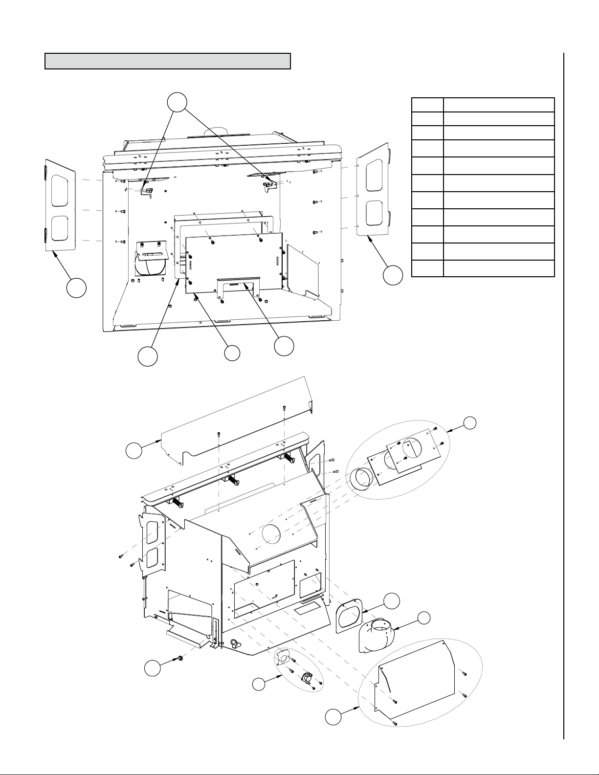
23
24
24
30
23
3
4
5
26
25
27
2
30
PART IDENTIFICATION
Item # Description
Air Intake Assembly
2
Blower Box Assembly
3
Flue Collar Assembly
4
Blower Snap Switch Assembly
5
Brick Panel Brackets
23
Surround Hanging Brackets
24
Upper Air Deflector
25
Blower Ducting
26
Wire Grommets
27
Gasket Kit
30
NOTE: DIAGRAMS AND ILLUSTRATIONS ARE NOT TO SCALE
31
Page 32

PART IDENTIFICATION
9
11
13
15
8
12
30
10
14
32
Item # Description
8 Burner Assembly
9 Pilot Assembly w/Shield
10 Main Orifice
11 Bulkhead Assembly
12 Cassette Plate Assembly
13 Valve Assembly
14 Air Shutter Assembly
15 Cassette Assembly
Gasket Kit
30
NOTE: DIAGRAMS AND ILLUSTRATIONS ARE NOT TO SCALE
Page 33

8
PART IDENTIFICATION
6
6
2
3
29
29
27
7
Item # Description
Air Intake Assembly
2
Blower Box Assembly w/Blower
3
Rear Leveling Leg Assembly
6
Outer Bottom Assembly
7
Burner Assembly
8
Wire Grommets
27
Front Leveling Leg Assembly
29
NOTE: DIAGRAMS AND ILLUSTRATIONS ARE NOT TO SCALE
33
Page 34

PART IDENTIFICATION
16
17
20
18
19
20
28
8
21
40
22
Item # Description
8 Burner Assembly
16 Louver Assembly
17 Blower Rheostat
18 Control Panel/Valve Cover
19 On/Off Switch
Item # Description
20 Igniter w/nut
21 Door Assembly
22 Ceramic Log Set
28 Burner Support
40 Power Cord
34
Ceramic Log Set
NOTE: DIAGRAMS AND ILLUSTRATIONS ARE NOT TO SCALE
Page 35

PART IDENTIFICATION
40
3-Piece Surround Assembly
Item # Description
Surround Flange Hinge
31
Ball Screw Assembly
32
Ball Screw Catch Assembly
33
Surround Spacer Kit - Small
34
Surround Spacer Kit - Large
35
Extrusion Kit, 3-Piece - Small
36
Extrusion Kit, 3-Piece - Large
37
Extrusion Kit, 4-Piece - Small
38
Extrusion Kit, 4-Piece - Large
39
32/33
4-Piece Surround Assembly
NOTE: DIAGRAMS AND ILLUSTRATIONS ARE NOT TO SCALE
35
Page 36

OPTIONAL ACCESSORIES
P
A
I
N
T
Wall Thermostat
Deluxe Remote Control System
The Model RCL-T (Deluxe) Remote Control
System has all of the features of the standard
system along with an added easy to read LCD
screen which presents access to many enhancements, including; battery power level indicator,
timer, mode of operation, thermostatic display
including room temperature in either metric
or English units, flame indicator and clock.
Fully programmable, the Model RCL-T allows
for command over nearly all operational and
temperature variables, using the hand held
remote control transmitter.
(ref. Form # 750,129M)
Cat. No. Model Description
H0251 RCL-T Remote Control System (Deluxe)
Standard Remote Control System
The Model RCL (Standard) Remote Control
System, features a simple On/Off control
function for the insert. This model includes a
hand-held transmitter, a remote receiver with
wall-mount coverplate and all hardware required
to install the unit. The remote receiver can be
wall or hearth mounted.
(ref. Form # 750,127M)
The wall thermostat kit provides temperature control for optimum
comfort.
Cat. No. Model Description
H4635 DWTK Wall Thermostat Kit, Digital
Screen Panel Kit
This screen panel kit can be installed over the glass enclosure panel to
help protect from making direct contact with the hot glass surface.
Cat. No. Model Description
H0249 RCL Remote Control System (Standard)
Fuel Conversion Kits
Converting your Shoreline™ gas insert between natural gas (40,00033,000 BTU’s) and LP (37,500-33,000 BTU’s) or vice versa can be
accomplished by installing a conversion kit (valve regulator for fuel
conversion and burner orifice). Only a qualified service technician should
perform the conversion.
(ref. Form # 750,241M-to LP, & 750,243M-to NG)
Cat. No. Model Description
75390 SHR-CK-NG to LP Natural Gas to Propane Conversion Kit
75393 SHR-CK-LP to NG Propane to Natural Gas Conversion Kit
(ref. Form # 775,234M)
Cat. No. Model Description
75392 SHR-GS-BLK Glass Screen Panel Kit, Black
Touch-Up Paint Kit
Repair of minor scratches and discoloration of the appliance's black painted
surfaces may be accomplished with the use of this touch-up paint kit.
Cat. No. Model Description
70K99 TSPK-B Touch-Up Paint Kit, Black
36
NOTE: DIAGRAMS AND ILLUSTRATIONS ARE NOT TO SCALE
Page 37

OPTIONAL ACCESSORIES
Surround Kits
These surround panels install around the insert body providing an
attractive finished look. Note: See Page 35 for additional information
on surround kits
Width
Small 3-sided - 36-5/8” Wide x 257/8” High (930 mm x 657 mm)
Large 3-sided - 41” Wide x 28” High
(1041 mm x 711 mm)
Height
Refractory Brick Panel Set (5 pieces)
These decorative brick panels sets are offered in 3 attractive styles. One
set required.
IMPORTANT NOTE: A refractory brick panel kit is required for proper
operation (sold separately). Never operate this appliance without
all the refractory brick panels properly installed.
Width
Small 4-sided - 36-5/8” Wide x 293/16” High (930 mm x 741 mm)
Large 4-sided - 41” Wide x 33-1/2”
High (1041 mm x 851 mm)
Height
Cat. No. Model Description
75385 SHR-SP-4P-SM Surround Panel Kits, 4 piece, Small
75386 SHR-SP-4P-LG Surround Panel Kits, 4 piece, Large
75387 SHR-SP-3P-SM Surround Panel Kits, 3 piece, Small
75388 SHR-SP-3P-LG Surround Panel Kits, 3 piece, Large
Standard
Brick
Red
Brick
Architectural
Stone
(ref. Form # 775,263M)
Cat. No. Model Description
H7987 SHR-BRK-STD Brick Panel Set, Tan
H7988 SHR-BRK-RED Brick Panel Set, Red
H7989 SHR-BRK-ARCHSTONE Brick Panel Set, Architectural (shown)
NOTE: DIAGRAMS AND ILLUSTRATIONS ARE NOT TO SCALE
37
Page 38

OPTIONAL ACCESSORIES
4 Gear clamps
Side View of Cap
Cap has two 3"
collars for
attachment of liners
Termination
Cap
Flashing
Vent Kits
Cat. No. Model Description
H0909 FKDVI Flex Liner Kit, DVI 3” X 35’ (requires 2,
one for exhaust and one for intake)
TKDVI TKDVI Termination Kit, DVI (termination cap and
flashing)
DV3FK35 DV3FK35 Flex Liner and Termination Kit, 3" X 35'
(includes 2 flex liners, termination and
gear clamps)
38
NOTE: DIAGRAMS AND ILLUSTRATIONS ARE NOT TO SCALE
Page 39

SAFETY / LISTING LABEL
MINIMUM CLEARANCES TO COMBUSTIBLES -
SHR40/SHR33
E = Top Facing to Bottom of Insert 35”
F = Center of Fireplace to Side Facing or Side Wall 30”
*J = 12” Mantel to Bottom of Insert 38”
* See owner’s manual for additional mantel clearances and options
MINIMUM FIREPLACE SIZES REQUIRED
A = 36.00” Front Opening
B = 21.50” Height
C = 19.50” Rear Width
D = 16.00” Fireplace Depth
HEARTH PROTECTION
G = Minimum Hearth Protection
G = from Front of Insert
H = Vertical Distance from Insert
H = Bottom to Combustible Material
Note: Hearth protection to be min. 1” thick non-combustible or equivalent, with a k factor of .84.
MODEL
MODÈLE
SHR 40
MANUFACTURED BY / FABRIQUÉ PAR:
LENNOX HEARTH PRODUCTS
PO BOX 987
AUBURN, WA., USA 98071
SHR
SERIAL
NO.
Report No. / Número de Rapport
050-F-22-5
H
MINIMUM
CLEARANCES
C
L
J
F
E
G
MANTEL
TRIM
LISTED VENTED GAS FIREPLACE HEATER - FIREPLACE INSERT - NOT FOR USE WITH SOLID FUEL
TESTED TO ANSI Z21.88-2005/CSA 2.33-2005 “VENTED GAS FIREPLACE HEATERS”, UL307b, CSA P.4.1-02, AND CGA 2.17-M91.
THIS APPLIANCE MUST BE INSTALLED IN ACCORDANCE WITH LOCAL CODES, IF ANY. IF NOT, FOLLOW THE CURRENT ANSI
Z223.1/NFPA 54-LATEST EDITION (USA) OR CAN/CGA B149.1-LATEST EDITION (CANADA). THIS APPLIANCE MUST BE INSTALLED
IN AC CORDANCE WITH THE MANUFACTURER’S INSTALLATION INSTRUCTION. FOR INSTALLATION IN SOLID FUEL B URNING
FIREPLACES ONLY - MASONRY OR FACTORY BUILT. THIS VENTED GAS FIREPLACE HEATER IS NOT FOR USE WITH AIR FILTERS.
THIS APPLIANCE IS ONLY FOR USE WITH THE TYPE OF GAS INDICATED ON THE RATING PLATE AND MAY BE INSTALLED IN AN
AFTERMARKET, PERMANENTLY LOCATED, MANUFACTURED (MOBILE) HOME WHERE NOT PROHIBITED BY LOCAL CODES. SEE
OWNER’S MANUAL FOR DETAILS. THIS APPLIANCE IS NOT CONVERTIBLE FOR USE WITH OTHER GASES UNLESS A CERTIFIED
KIT IS USED.
DANGER: RISK OF ELECTRICAL SHOCK. DISCONNECT POWER BEFORE SERVICING UNIT.
IF ELECTRICALLY CONNECTED, CONNECTIONS AND G ROUNDING MUST BE IN ACCORDANCE WITH LOCAL CODES, IF ANY.
IF NOT, FOLLOW THE CURRENT NATIO NAL ELECTRICAL CODE ANSI/NFPA 70-LATEST EDITION (USA) OR CSA C22-1-LATEST
EDITION (CANADA).
CHIMNEY - USE 3” DIAMETER SINGLEWALL OR FLEX GAS VENT CHIMNEY OR LINER LISTED TO UL1777.
THIS APPLIANCE MUST BE PROPERLY CONNECTED TO A VENTING SYSTEM IN ACCORDANCE WITH THE MANUFACTURER’S
INSTALLATION INSTRUCTIONS.
FOR ALTITUDES ABOVE 2,000 FT/610M (IN CANADA 4500 FT/1370M) DE-RATE THE APPLIANCE BY FOUR (4)% FOR EVERY
1,000 FT (405 M).
CAUTION:
HOT WHILE IN OPERATION. DO NOT TOUCH. SEVERE BURNS MAY RESULT. KEEP
CHILDREN, CLOTHING, FURNITURE, GASOLINE AND OTHER LIQUIDS HAVING FLAMMABLE VAPORS
AWAY. KEEP BURNER AND CONTROL COMPARTMENT CLEAN. SEE INSTALLATION AND OPERATING
INSTRUCTIONS ACCOMPANYING APPLIANCE. FOR USE WITH GLASS DOORS CERTIFIED WITH THIS
APPLIANCE ONLY. DO NOT OPERATE THE APPLIANCE WITH GLASS REMOVED, CRACKED OR BROKEN.
REPLACEMENT OF THE PANEL(S) SHOULD BE DONE BY A LICENSED OR QUALIFIED PERSON.
WARNING: IMPROPER INSTALLATION, ADJUSTMENT, ALTERATION, SERVICE OR MAINTENANCE CAN
CAUSE INJURY OR PROPERTY DAMAGE. REFER TO THE OWNER’S INFORMATION MANUAL PROVIDED
WITH THIS APPLIANCE. FOR ASSISTANCE OR ADDITIONAL INFORMATION CONSULT A QUALIFIED
INSTALLER, SERVICE AGENCY OR GAS SUPPLIER.
DO NOT REMOVE OR COVER THIS LABEL
Part No./ No. pièce #36256 Rev. A, 12/06
FACTORY EQUIPPED FOR NATURAL GAS. IF CONTROL PANEL CONTRADICTS THIS LABEL, UNIT FUEL TYPE HAS BEEN CONVERTED.
CET APPAREIL EST MUNI D’ÉQUIPEMENT POUR L’USAGE DU GAZ NATUREL. SI L’ÉTIQUETTE DU PANNEAU DES COMMANDES CONTREDIT
CETTE ÉTIQUETTE, C’EST QUE LE TYPE DE CARBURANT DE CET APPAREIL A ÉTÉ CONVERTI.
DÉGAGEMENTS AUX COMBUSTIBLES -
SHR40/SHR33
E = Dessus du foyer à partir de la base 35”
F = Mur latéral à partir du centre du foyer 30”
*J = 12” manteau de foyer à partir de la base 38”
* Voir le manuel d’entretien pour les informatinos supplémentaires reliées
aux distances à respecter pour le manteau de foyer
DIMENSIONS MINIMUMS DE FOYER REQUISES
A = 36.00” Ouverture avant
B = 21.50” Hauteur
C = 19.50” Largeur arrière
D = 16.00” Profondeur du foyer
PROTECTION DU FOYER
G = Extension d’âtre min. devant
G = le foyer
H = Distance verticale de la base de
H = l’appareil aux combustibles
Note: Extension d’âtre fabriqué avec 1” minimum de matériaux non-combustible ou équivalent possédant un facteur k de 0.84.
H
DÉGAGEMENTS
MINIMUMS
C
L
J
F
E
G
MANTEAU
DE FOYER
PIÈCE DE
FINITION
HOMOLOGUÉ FOYER RADIANT PRÉFABRIQUÉ AU GAZ - INSERTION DE FOYER AU GAZ - NE PAS
UTILISER AVEC DU COMBUSTIBLE SOLIDE
TESTÉ SELON LA NORME ANSI Z21.88-2005/CSA 2.33-2005 «FOYER RADIANT AU GAZ», UL307B, CSA P.4.1-02, ET CGA 2.17-M91.
CET APPAREIL DOIT ÊTRE INSTALLÉ CONFORMÉMENT AUX EXIGENCES DES CODES RÉGIONAUX ET DU CODE D’INSTALLATION
ANSI NFPA 54-DERNIÈRE ÉDITION (ETATS-UNIS), OU CAN/CGA-B149.1-DERNIÈRE ÉDITION (CANADA). CET APPAREIL DOIT ÊTRE
INSTALLÉ SELON LES DIRECTIVES D’INSTALLATION DU FABRICANT. POUR INSTALLATION DANS DES FOYERS À COMBUSTIBLE
SOLIDE SEULEMENT - DE MAÇONNERIE OU PRÉFABRIQUÉ EN USINE. CE FOYER RADIANT AU GAZ À ÉVACUATION N’EST PAS
CONÇU POUR ÊTRE UTILISÉ AVEC DES FILTRES À AIR.
CET APPAREIL DOIT ÊTRE UTILISÉ AVEC LE TYPE DE GAZ INDIQUÉ SUR LA PLAQUE SIGNALÉTIQUE ET PEUT ÊTRE INSTALLÉ
DANS UNE MAISON PRÉUSINÉE OU DANS UNE MAISON MOBILE FIXE, LÀ OÙ LES CODES RÉGIONAUX LE PERMETTENT. VOIR LE
MANUEL D’ENTRETIEN POUR PLUS DE DÉTAILS. CET APPAREIL NE PEUT PAS ÊTRE CONVERTI POUR L’USAGE AVEC D’AUTRES
TYPES DE GAZ À MOINS D’UTILISER UNE TROUSSE DE CONVERSION HOMOLOGUÉE.
DANGER: RISQUE DE CHOC ÉLECTRIQUE. DÉBRANCHEZ L’APPAREIL AVANT D’EN FAIRE L’ENTRETIEN.
SI L’APPAREIL REQUIERT UN BRANCHEMENT ÉLETRIQUE, LES RACCOR DEMENTS ET LA MISE À LA TERRE DOIVENT ÉTRE
CONFORMES AUX EXIGENCES DES CODES RÉGIONAUX ET DU CODE D’INSTALLATION ANSI/NFPA 70 OU CSA C22-1.
CHEMINÉE - UTILISER UN CONDUIT D’ÉVACUATION 3” DE DIAMÈTRE RIDIGE OU FLEXIBLE HOMOLOGUÉ UL 1777.
CET APPAREIL DOIT ÊTRE RELIÉ À UN SYSTÈME D’ÉVACUATION TEL QUE SPÉCIFIÉ DANS LE MANUEL D’INSTALLATION DU
FABRICANT.
EN ALTITUDE, AU-DELÀ DE 2000 PI/610 M, (AU CANADA 0-4500 PI/0-1370M) LA CAPACITÉ ÉNERGÉTIQUE DE L’APPAREIL
DIMINUE DE QUATRE (4)% POUR CHAQUE 1000 PI (405 M).
DANGER:
CET APPAREIL DÉGAGE DES TEMPÉRATURES ÉLEVÉES ET DEVRAIT ÊTRE INSTALLÉ À L’ÉCART DES
ENDROITS TRÈS PASSANTS ET LOIN DES MEUBLES ET RIDEAUX. SURVEILLEZ LES ENFANTS QUI SE TROUVENT DANS
LA PIÈCE. GARDEZ LA ZONE AUTOUR DU FOYER EXEMPTE DE MATÉRIAUX COMBUSTIBLES, D’ESSENCE ET AUTRES
VAPEURS ET LIQUIDES INFLAMMABLES. MAINTENEZ LE BRÛLEUR ET LE BOÎTIER DES COMMANDES PROPRE EN TOUT
TEMPS. VOIR LES MANUELS D’INSTALLATION ET D’ENTRETIEN QUI ACCOMPAGNENT L’APPAREIL. SEUL LE PANNEAU
VITRÉ FOURNI PAR LE MANUFACTURIER PEUT ÊTRE UTILISÉ AVEC CET APPAREIL. EN AUCUN CAS, L’APPAREIL NE
PEUT ÊTRE UTILISÉ SANS LA VITRE OU AVEC LA VITRE BRISÉE. LE REMPLACEMENT DE LA VITRE DOIT ÊTRE EFFECTUÉ
PAR UN TECHNICIEN DE SERVICE QUALIFIÉ.
AVERTISSEMENT: UNE INSTALLATION INADÉQUATE DE MÊME QU’UN AJUSTEMENT, UNE MODIFICATION, UNE
RÉPARATION OU UN ENTRETIEN INCORRECTS PEUVENT CAUSER DES BLESSURES OU DOMMAGES À LA PROPRIÉTÉ.
RÉFÉREZ-VOUS AU MANUEL D’ENTRETIEN LIVRÉ AVEC CET APPAREIL. POUR DE L’ASSISTANCE, CONSULTEZ UN
INSTALLATEUR QUALIFIÉ, UNE ENTREPRISE DE SERVICE OU UN FOURNISSEUR DE GAZ.
DATE OF MANUFACTURE / DATE DE FABRICATION
2007 2009 20102008
JANV
JAN
FEVR
FEB
MARS
MAR
AVR
APR
MAI
MAY
JUIN
JUN
JUIL
JUL
AOÛT
AUG
SEPT
SEP
OCT
OCT
NOV
NOV
DEC
DEC
IGN 06-2835
N’ENLEVEZ PAS OU NE COUVREZ PAS CETTE ÉTIQUETTE
SHR40/33
G 12” 0”
H 0” 8”
SHR40/33
G 12” 0”
H 0” 8”
SPÉCIFICATIONS Modèle SHR40 Modèle SHR33
GAZ NATUREL GAZ PROPANE GAZ NATUREL GAZ PROPANE
ENTRÉE MAX/MIN BTU/HR 0-4500 pi (0-1370
M)*
40000/24000 37500/21500 33000/19500 33000/19500
PRESSION À LA SORTIE (IN. WC/C.E.) 3,5 10,0 3,5 10,0
PRESSION MINIMUM D’ENTRÉE DU GAZ
(IN. WC/C.E.)
5,0 10,5 5,0 10,5
ORIFICE (DMS) 0-4500 pi (0-1370 M)* ,125 #49 #36 #51
* L’APPAREIL PRÉUSINÉ EST MUNI D’ÉQUIPEMENT POUR 0-2000 PIEDS (0-610 M). AU CANADA 0-4500 PIEDS (0-1370M).
SPÉCIFICATIONS ÉLECTRIQUE 120 VCA, 60 HZ, MOINS DE 2 AMPÈRES
RATINGS Model SHR40 Model SHR33
NATURAL GAS LP GAS NATURAL GAS LP GAS
MAX/MIN INPUT BTUH 0-2,000 FT (0-610 M)* 40,000/24,000 37,500/21,500 33,000/19,500 33,000/19,500
MANIFOLD PRESSURE (IN. WC) 3.5 10.0 3.5 10.0
MIN. INLET PRESSURE (IN. WC) 5.0 10.5 5.0 10.5
ORIFICE (DMS) 0-2,000 FT (0-610 M) * .125 #49 #36 #51
*UNIT FACTORY EQUIPPED FOR 0-2000 FT/0-610 M, IN CANADA 0-4500 FT/0-1370 M
ELECTRICAL RATING: 120 VAC, 60 HZ, LESS THAN 2 AMPS
US
Portland
NOTE: DIAGRAMS AND ILLUSTRATIONS ARE NOT TO SCALE
2010 2011 2012 2013
39
Page 40

LIGHTING INSTRUCTIONS LABEL
FOR YOUR SAFETY READ BEFORE OPERATING
1. To turn off the burner, switch the rocker switch to “OFF” or adjust the thermostat to a setting below room temperature
(if installed). The pilot will remain lit for future burner ignition.
For complete shutdown: See “TO TURN OFF GAS TO APPLIANCE” above.
SHUTDOWN PROCEDURE
OPERATING INSTRUCTIONS
WARNING:
IF YOU DO NOT FOLLOW THESE INSTRUCTIONS EXACTLY, A FIRE OR E XPLOSION MAY RES ULT CAUSI NG
PROPERTY DAMAGE, INJURY OR LOSS OF LIFE.
CAUTION:
HOT WHILE IN OPERATION. DO NOT TOUCH. KEEP CHILDREN, FURNITURE, GASOLINE AND OTHER LIQUIDS WITH
FLAMMABLE VAPORS AWAY. NEVER OPERATE UNIT WITH GLASS DOOR OFF OR ATTEMPT TO OPEN THE DOOR WHILE HOT.
A. This appliance is equipped with a piezo ignition device to light the pilot. When lighting the pilot, follow these instructions exactly.
B. BEFORE LIGHTING, smell around the appliance area for gas. Be sure to smell next to the floor because some gas is heavier than air
and will settle on the floor.
WHAT TO DO IF YOU SMELL GAS:
• DO NOT try to light the appliance.
• DO NOT touch any electric switch; do not use any phone in the building.
• Immediately call your gas supplier from a neighbor's phone. Follow the gas supplier's instructions.
• If you cannot reach your gas supplier, call the fire department.
C. Use only your hand to push in or turn the gas control knob. Never use any tool. If the knob will not push in or turn by hand, don't try
to repair it, call a qualified service technician. Force or attempted repair may result in a fire or explosion.
D. DO NOT use this appliance if any part has been under water. Immediately call a qualified service technician to inspect the appliance
and to replace any part of the control system and any gas control which has been under water.
CAUTION: YOUR LENNOX GAS APPLIANCE MUST ALWAYS BE OPERATED WITH GLASS DOOR IN PLACE.
STOP! Read the safety information above before proceeding.
1. Open the right side acc ess door. M ake sure gas supply shut-off cocks are open and
ON/OFF Rocker Switch is “OFF”. If equipped with a thermostat, set it to the lowest setting.
2. Turn off all electrical power to the appliance.
3. Push in Gas Control Knob slightly and turn clockwise to “OFF”.
NOTE: Knob cannot be turne d from “PILOT” to “OFF” unless Knob is pushed in slightly.
Do not force.
4. Wait five (5) minutes to clear out an y gas. If you smell gas, STOP! Follow “B” a bove.
If you don’t smell gas continue.
5. Loca te t he p ilot by looking at the rear cen ter of t he b urner, behind the lar ge c enter
log. Blue flame will be seen when the pilot is lit.
6. Turn the gas control knob counterclockwise to the “PILOT” position.
7. Push the knob all the way i n and hold in that position . Imme diately light the pilot by
pres sing the ignitor button several times until pilot is lit. Continue to hold the knob in
for about 30 seconds after the pi lot is lit. Release knob and i t will pop back out. P ilot
sh ould r emain l it. If it goes out, r epeat s teps 4 -8 hold ing kno b in an additi onal
15 seconds after pilot is lit.
• If kn ob does n ot pop ou t when re leased , stop an d immed iately c all you r servi ce
technician or gas supplier.
• If the pilot will not stay lit after several tries, turn the gas control knob to “OFF” and call your
service technician or your gas supplier.
8. After pilot is lit, turn gas control counte rclockwise to “ON”. Knob can only be
turned “ON” if the knob has popped out.
9. To turn burner on, turn “ON/ OFF” rocker switch to “ON” or set the thermo stat to t he
desired temperature above room temperature.
10. Adjust the flame height (and heat output) by turning the flame height knob clockwise
for reduced flame and counterclockwise for full flame.
11. Set the bl ower to the des ired air flow af ter it turns on wh en the appli ance reac hes
operating temperature.
1. Turn off the “ON/OFF” rocker switch and/or thermostat (if installed).
2. Turn off electric power to the appliance if service is to be performed.
3. Turn gas control knob clockwise to "OFF". Do not force.
This appliance needs fresh air for safe operation and must be installed so there are provisions for adequate
combustion and ventilation air. See Installation and Operation Manual accompanying appliance.
WARNING: Improper installation, adjustment, alteration, service or maintenance can
cause injury or property damage. For assistance or additional information, consult a
qualified installer, service agency or your gas supplier.
Operation of this appliance when not connected to a properly installed and maintained venting system can result
in carbon monoxide (CO) poisoning and possible death.
TO TURN OFF GAS TO APPLIANCE
POUR VOTRE SÉCURITÉ, LIRE AVANT L’ALLUMAGE
1. Fermez l’interrupteur et/ou le thermostat «MARCHE/ARRÊT».
2. Coupez l’alimentation électrique de l’appareil si vous prévoyez en faire le service.
3. Tournez le bouton de commande du gaz dans le sens des aiguilles d’une montre à “OFF”. Ne le forcez pas.
Cet appareil a besoin d’air frais pour opérer sécritairement et doit être installé pour qu’il y ait un apport en air suffisant. Référezvous aux manuels d’entretien et d’installation fournis avec l’appareil.
AVERTISSEMENT: Une installation inadéquate, un mauvais ajustement, une altération ou toutes autres modifications
inappropriés pourraient entraîner des blessures physiques et/ou des dommanges matériels. Référez-vous au guide
d’utilisation fourni avec ce foyer. Pour assistance ou information supplémentaires contactez un installateur qualifié,
un agent de service ou un fournisseur de gaz.
Si vous opérez cet appareil s ans qu’il ne s oit correctement racc ordé à un cond uit d’évacuati on, vous pourriez risquer d’ê tre
empoisonné au monoxyde de carbone (CO) ce qui pourrait entraîner des conséquences grave ou la mort.
POUR COUPER L’ALIMENTATION EN GAZ DE L’APPAREIL
1. Pou r arrête r le brûleur, mettre l’interrupteur à la po sition “ OFF” ou ajustez le therm ostat à une température en dessous de la
température ambiante. La veilleuse restera allumée pour permettre un alummage ultérieur.
Pour un arrêt complet: Consultez la procédure ci-dessus «POUR COUPER L’ALIMENTATION EN GAZ DE L’APPAREIL».
PROCÉDURE D’ARRÊT
ALLUMAGE
AVERTISSEMENT:
SI VOUS NE RESPECTEZ PAS RIGOUREUSEMENT LES INSTRUCTIONS CI-DESSOUS, VOUS POURRIEZ ENCOURIR UN RISQUE D’INCENDIE ET/OU
D’EXPLOSION QUI POURRAIENT CAUSER DES DOMMANGES MATÉRIELS ET CORPORELS POUVANT ENTRAÎNER LA MORT.
DANGER:
CET APPAREIL DÉGAGE DES TEMPÉRATURES ÉLEVÉES ET DEVRAIT ÊTRE INSTALLÉ À L’ÉCART DES ENDROITS TRÈS PASSANTS ET LOIN DES MEUBLES ET
RIDEAUX. GARDEZ LA ZONE AUTOUR DU FOYER EXEMPTE DE MATÉRIAUX COMBUSTIBLES, D’ESSENCE ET AUTRES VAPEURS ET LIQUIDES INFLAMMABLES.
A. Cet appareil utilise un système d’allumage par étincelle (allumeur Piézo-électrique) pour allumer la veilleuse. Assurez-vous de suivre
rigoureusement les instructions d’allumage de la veilleuse.
B. AVANT D’ALLUMER L’APPAREIL, assurez-vous qu’il n’y a pas d’odeur de gaz près de l’appareil ni près du sol car certains gaz plus
lourds que l’air auraient tendance à s’y accumuler en cas de fuite.
QUE FAIRE SI VOUS SENTEZ UNE ODEUR DE GAZ:
• N’ALLUMEZ aucun appareil.
• Ne touchez aucune prise électrique; N’utilisez aucun téléphone dans votre édifice.
• Sortez de la maison. À partir d’un autre endroit, appelez immédiatement votre fournisseur de gaz et suivez les directives.
• S’il est impossible de joindre le distributeur du gaz, appelez les pompiers.
C. N’utilisez aucun outil pour tourner ou pousser le dispositif de contrôle du gaz. Si vous ne pouvez le faire manuellement, n’essayez
pas de réparer l’appareil. Appelez un technicien de service qualifié. Si vous tentez de forcer ou réparer le dispositif de contrôle du gaz
vous pourriez encourir un risque d’incendie et/ou d’explosion.
D. N’utilisez pas cet appareil si une de s es composantes a été émergée dans l’eau. Appelez immédiatement un technicien de service
qualifié et reconnu afin qu’il inspecte et remplace au besoin toutes pièces du système qui auraient été en contact avec l’eau.
DANGER: VOTRE APPAREIL AU GAZ LENNOX DOIT ÊTRE OPÉRÉ AVEC DES PORTES DE VERRE.
ATTENTION! Lisez les consignes de sécurité ci-dessous avant d’opérer votre appareil.
1. Ouvrez la porte d’accès à la droite de l’appareil. Assurez-vous que l’alimentation en gaz est à la position Fermée “OFF”. Si l’appareil est
équippé d’un thermostat, placez-le à la température la plus basse.
2. Couper le courant électrique qui alimente l’appareil.
3. Enfoncez légèrement le bouton de contrôle du gaz et tournez-le dans le sens des aiguilles d’une montre à la position “OFF”.
NOTE: Le bouton de contrôle du gaz ne peut être tourné de la position “PILOT” à “OFF” sans qu’une légère pression ne soit appliquée.
4. Attendez au moins 5 minutes pour que le gaz qui se trouve dans la chambre de combustion puissse s’échapper. Si vous sentez une
odeur de gaz ARRÊTEZ! Référez-vous à la section B ci-dessus. Si vous ne sentez pas d’odeur de gaz, allez à la prochaine étape.
5. Repérez la veilleuse située au centre de la chambre de combustion, sous la bûche céramique arrière. Une flamme bleue est visible
lorsque la veilleuse est allumée.
6. Tournez le bouton de contrôle de gaz dans le sens inverse des aiguilles d’une montre pour le placer sur “PILOT”.
7. Cet appareil de chauffage est equipé d’un système d’allumage par étincelle (allumeur Piézo-électirque), devant être utilisé pour
l’allumage de la veilleuse. Poussez complètement le bouton de contrôle du gaz et le maintenir dans cette position. Appuyez
immédiatement sur le bouton (allumeur Piézo-électrique) situé à gauche du robinet de contrôle du gaz.L’étincelle produite par
l’allumeur Piézo-électrique doit allumer la veilleuse. Continuez à maintenir le bouton de contrôle dans cette position pendant environ 30
secondes après l’allumage de la veilleuse. Relâchez le bouton de contrôle du gaz qui reviendra à la position initiale. La veilleuse doit
rester allumée. Répétez les étapes 4 à 8 pendant 15 secondes supplémentaires si la veilleuse s’éteind.
• Si le bouton de contrôle du gaz ne revient pas à la position initiale une fois relâché, appeler immédiatement un technicien qualifié ou
votre distributeur de gaz.
• Si la veileuse ne reste pas allumée après plusieurs essais, tournez le bouton de contrôle du gaz à la position “OFF” et appelez
immédiatement un technicien qualifié ou votre distributeur de gaz.
8. Lorsque la veilleuse est allumée, tournez le bouton de contrôle du gaz dans le sens invers des aiguilles d’une montre pour le
placer à la position “ON”. Le bouton de contrôle peut-être tourné à la position “ON” seulement si il n’est plus enfoncé.
9. Pour allumer le brûleur, mettre l’interrupteur à la position “ON” ou ajustez le thermostat à la température souhaitée.
10. Ajustez la flamme et la température souhaitée en tournant le bouton de réglage de la flamme dans les sens des aiguille d’une montre
pour l’abaisser et dans le sens contraire pour l’augmenter.
11. Ajustez le ventilateur au volume désiré lorsque l’appareil aura atteint la température de fonctionnement.
#36256 Rev. A, 12/06
Gas Control
Knob
(Pilot / On / Off)
Bouton de
contrôle
(V eilleuse/
Ouverte / Fermée)
Flame Height
Control Knob
(Hi / Lo)
Bouton de
réglage
de la flamme
HEIGHT
FLAME
MAIN BURNER
CONTROL
GAS
HI
LO
OFF
ON
PILOT
PILOT ASSEMBLY
Thermopile
Veilleuse à gaz
Igniter (electrode)
Allumeur
Thermocouple
Gas Pilot Hood
40
NOTE: DIAGRAMS AND ILLUSTRATIONS ARE NOT TO SCALE
Page 41

NOTES
41
Page 42

WARRANTY
Your gas appliance is covered by a limited warranty (see warranty
certificate provided with appliance). Please read the warranty to be
familiar with its coverage.
Retain this manual. File it with your other documents for future reference.
PRODUCT REFERENCE INFORMATION
We recommend that you record the following important information about
your fireplace. Please contact your Lennox dealer for any questions or
concerns. For the number of your nearest Lennox dealer, please call
1-800-9-LENNOX.
REPLACEMENT PARTS
See Page 30 for a complete replacement parts list. Use only parts supplied from the manufacturer.
Your Fireplace Insert's Model Number ___________________________________
Your Fireplace Insert’s Serial Number ___________________________________
Normally, all parts should be ordered through your Lennox distributor or
dealer. Parts will be shipped at prevailing prices at time of order.
When ordering repair parts, always give the following information:
1. The model number of the appliance.
2. The serial number of the appliance.
3. The part number.
4. The description of the part.
5. The quantity required.
6. The installation date of the appliance.
If you encounter any problems or have any questions concerning the
installation or application of this system, please contact your dealer.
LENNOX HEARTH PRODUCTS
1508 Elm Hill Pike, Suite 108
Nashville, TN 37210
visit us at www.Lennox.com
The Date On Which Your Fireplace Insert Was Installed ______________________
The Type of Gas Your Fireplace Insert Uses _______________________________
Your Dealer's Name _________________________________________________
Fuel Type (Check one) c Natural Gas c Propane Gas (LP)
Lennox Hearth Products reserves the right to make changes at any time, without notice, in
design, materials, specifications, prices and also to discontinue colors, styles and products.
Consult your local distributor for fireplace code information.
Printed in U.S.A. © Lennox Hearth Products 2007
P/N 850,050M REV. D 03/2010
42
1508 Elm Hill Pike, Suite 108 • Nashville, TN 37210
 Loading...