

Lennox 41718L098, SCU, SCU 12, SCU 13, SCU E Installation And Maintenance Instructions Manual
Page 1

INSTALLATION AND MAINTENANCE
INSTRUCTIONS
SCU Series
Split System Air Conditioner
WARNING
The equipment covered in this manual is to be installed by trained and experienced
service and installation technicians. Improper installation, modification, service or use
can cause electrical shock, fire, explosion or other conditions which may cause personal injury, death or property damage. Use appropriate safety gear including safety
glasses and gloves when installing this equipment.
WARNING
Risk of electrical shock. Disconnect all remote
power supplies before installing or servicing
any portion of the system. Failure to disconnect power supplies can result in property
damage, personal injury or death.
WARNING
Installation and servicing of air conditioning
equipment can be hazardous due to internal
refrigerant pressure and live electrical components. Only trained and qualified service
personnel should install or service this equipment. Installation and ser vice performed by
unqualified persons can result in property
damage, personal injury or death.
WARNING
Before performing maintenance operations on
system, turn off all main power switches to
indoor and outdoor units. Turn off accessory
heater power switch if applicable. Electrical
shock could cause personal injury or death.
TABLE OF CONTENTS
INSTALLATION....................................... 2
START-UP .............................................. 5
MAINTENANCE ..................................... 5
WIRING DIAGRAMS.............................. 6
WARRANTY........................................... 8
Manufactured By
A.A.C.
A Lennox International Company
421 Monroe Street
Bellevue, OH 44811
# 41718L098 Page 1
Save these instructions for future reference
Page 2

INSTALLATION
General
Read this entire instruction manual, as well as the
instructions supplied in separate equipment, bef ore
starting the installation. Observe and follow all
warnings, cautions, instructional labels and tags.
Failure to comply with these instructions could result
in an unsafe condition and/or premature component
failure.
These instructions are intended as a general guide only
for use by qualified personnel and do not supersede any
national or local codes in any way. The installation m ust
comply with all provincial, state and local codes as well as
the National Electrical Code (U.S.) or Canadian Electrical
Code (Canada). Compliance should be determined prior
to installation.
This unit has been factory charged with a quantity of
refrigerant (R22) sufficient for a matched indoor coil
and 20 feet of refrigerant tubing. If installed with other
indoor sections or with tubing sets other than 20 feet in
length, adjustments to the total system charge must be
made.
The unit has been designed to operate within the range of
indoor and outdoor temperatures as outlined in Table 1.
Following these recommendations will minimiz e component failures and maximize system perf ormance.
Optimum T emperature Range
roodtuO
roodnI
* If extended run times are anticipated below
outdoor temperatures of 65° F, a low ambient kit
must be installed.
ot)muminim(*F°56
)mumixam(F°511
otbwF°75/bdF°26
bwF°27/bdF°09
Table 1
Location of Unit
Install the unit on a solid, level mounting pad. To minimize
transmission of vibration, the pad should not be in direct
contact with any building walls or f oundations.
This outdoor unit has been ARI rated with sev eral Armstrong matching indoor sections for various types of
installations. To obtain optimum performance, a matched
indoor section must be installed. ARI ratings are based on
properly charged systems running at rated indoor cfm
levels . Ductwork should be specified to insure the correct
indoor airflow is obtainable.
Inspection of Shipment
Upon receipt of equipment, carefully inspect it for possible
shipping damage. If damage is f ound, it should be noted
on the carrier’s freight bill. Take special care to examine
the unit inside the carton if the carton is damaged. An y
concealed damage discovered should be reported to the
last carrier immediately , pref erab ly in writing, and should
include a request for inspection by the carrier’ s agent.
If any damages are discovered and reported to the carrier
DO NOT INSTALL THE UNIT, as c laim may be denied.
Check the unit rating plate to confirm specifications
are as ordered.
Limitations
This unit is designed and approved for outdoor use
only .
The outdoor unit must not be installed with any ductwork
in the airstream. The outdoor fan is not designed to
operate against any additional static pressure.
This unit has been designed to be located outdoors with
sufficient clearance for free entrance to the inlet and
discharge air openings. Adequate service clearance must
also be provided. Refer to Figure 1 for a detailed description of minimum clearances. Position the unit to avoid
direct contact of water , sno w or ice from a roof line
overhead.
Av oid placing the unit near quiet areas suc h as
sleeping quarters or study rooms. Normal operating
sound levels may be objectionable if the unit is placed
near certain rooms.
Electrical Wiring
All field wiring must be done in accordance with the
National Electrical Code recommendations, Canadian
Electrical Code and CSA Standards, or local codes, where
applicable. Refer to the unit rating plate for information
needed for wire sizing and branch circuit protection. An
adequately sized branch circuit disconnect should be
installed, per the NEC, within sight of and readily accessible to the unit. Route properly sized copper conductors
from the disconnect to the unit high voltage connections at
the contactor. A properly sized ground wire must be
connected to the ground screw or wire located in the
control panel. T wo low voltage thermostat wires must be
connected to the yellow wires connected to the contactor
coil. Use copper conductors only.
Page 2 # 41718L098
Page 3

12" CLEARANCE
48" OVERHEAD
CLEARANCE
Minimum Clearances
WEATHERPROOF
DISCONNECT
SWITCH
NEC CLASS 1
WIRING
TO
POWER
SUPPLY
NEC CLASS 2
WIRING
THERMOSTAT
TO
INDOOR
UNIT
TO
EVAPORATOR
COIL
NAMEPLATE
LOCATION
12" CLEARANCE
BOTH SIDES
NOTE: ALL OUTDOOR WIRING
MUST BE WEATHERPROOF
24" SERVICE
ACCESS CLEARANCE
Figure 1
Refrigerant Piping Connections
Check the indoor piston orifice to see if it matches the
required piston for the indoor and outdoor combination being installed. Refer to the refrigerant char ge
label located on the inside of the outdoor unit access
panel for the correct piston orifice size requirements.
Replace the piston orifice with the correct size if this
size is not already installed in the indoor coil.
For optimum system performance, indoor coils
should be washed with a suitable detergent to remove
any residue from the coil manufacturing processes.
Refer to the follo wing instructions when making the
refrigerant piping connections:
SEAL OPENING(S)
WITH PERMAGUM
OR EQUIVALENT
3. Route tubing to fittings on the outdoor unit vapor and
liquid service valves using properly sized refrigerant
grade tubing. Run the refrigerant tubing in as direct a
path as possible avoiding unnecessary turns and
bends.
4. Ensure that the vapor line is insulated properly and
that both vapor and liquid lines are not in direct
contact with floors, walls, ductwork, floor joists or
other piping.
5. After wrapping the service valves with a wet rag,
braze the tubing to the valve connections .
6. After brazing the tubing connections at the indoor coil,
leak test the refrigerant tubing and indoor coil.
1. The unit has been factory charged with refrigerant
(R22) suitable for a matched indoor coil and 20 f eet of
properly sized refrigerant tubing. Ref er to the unit
rating plate for the e xact amount of this f actory charge.
2. Refer to the refrigerant charge label located on the
inside surface of the outdoor unit access panel.
Locate the outdoor and indoor models being installed
and note any refrigerant adjustments that must be
made to the system. Adjustments to the system
charge must also be made if an interconnecting line
set other than 20 feet is installed.
# 41718L098 Page 3
7. Following the leak test, e vacuate the indoor coil and
line set to a minimum of 500 microns to remove
contamination and moisture.
8. After evacuation, open both the vapor and liquid
service valves fully.
Page 4
Factory charge contains refrigerant for condenser, evaporator and 20 feet of 3/8” line set. For line set other than 20
feet, adjust charge at 0.60 oz. per foot of 3/8” o.d. liquid
line and 1.2 oz. per foot of 1/2”. T o obtain optimum
performance, system charge should be weighed in
accordance to amount specified on unit rating plate and
any adjustments for additional line length o v er 20 f eet, as
stated above.
System performance may be verified by using the
refrigerant charging labels provided with each unit.
In air conditioning systems, horizontal suction lines should
be slightly sloped toward the condensing unit. Piping must
avoid dips or low spots can collect oil. To aid in the return
of oil, a trap should be installed at the bottom of any
suction riser. The top end of the riser must be pitched
toward the compressor. F or long v ertical risers, additional
traps are recommended for each additional 20 f eet of pipe
to insure proper oil movement.
A crankcase heater is recommended for applications
where additional field added charge results in a system
with a reciprocating compressor requiring more than 6 lbs.
of refrigerant or a scroll compressor requiring more than
10 lbs. of refrigerant.
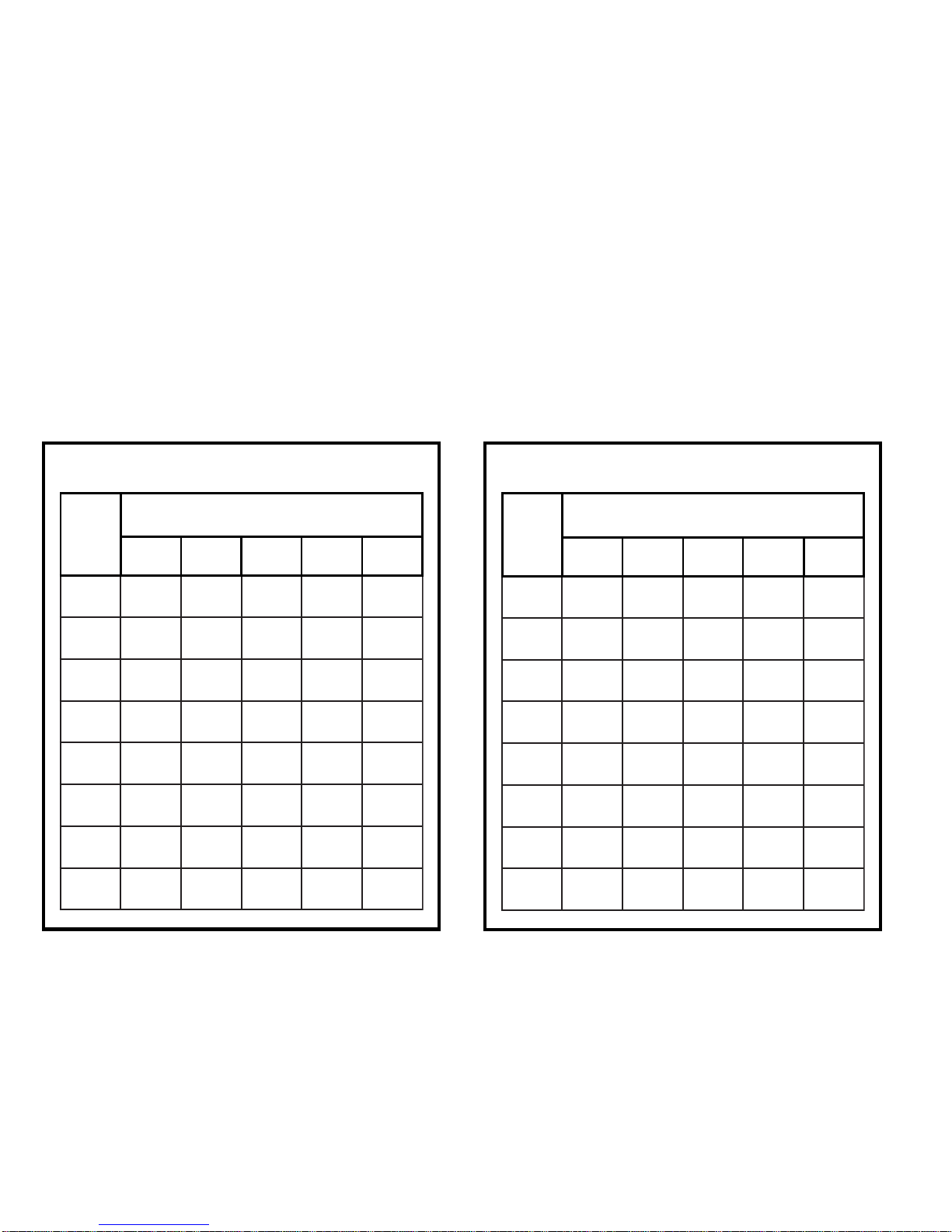
Suction Line Sizes
LINE SET LENGTH AND SIZE
BTU/HR 12 FT. 25 FT. 50 FT. 75 FT. 100 FT.
000,214/34/34/34/34/3
000,814/34/34/34/34/3
000,424/34/34/34/38/7
000,034/34/34/38/78/7
000,638/78/78/78/78/11
000,248/78/78/78/118/11
000,848/78/78/78/118/11
000,068/78/78/78/118/11
Liquid Line Sizes
LINE SET LENGTH AND SIZE
BTU/HR 12 FT. 25 FT. 50 FT. 75 FT. 100 FT.
000,218/38/38/38/38/3
000,818/38/38/38/38/3
000,428/38/38/38/38/3
000,038/38/38/38/32/1
000,638/38/38/38/32/1
000,248/38/38/32/12/1
000,848/38/38/32/12/1
000,068/38/38/32/12/1
Table 2
Table 3
For installations exceeding 100 feet, contact the Armstrong Air Conditioning Inc.
Technical Services Department at (419) 483-4840.
Page 4 # 41718L098
Page 5
The procedure for start-up of the unit is as follows:
1. Operate the unit for a period of at least 15 minutes to
allow for pressures and temperatures to stabiliz e.
Unless matched with an indoor section using an
expansion valv e, the superheat method can be used
to check the system refrigerant charge. It should be
noted that this method is not accurate at low load
conditions or at outdoor ambients above 106° F.
MAINTENANCESTART-UP
WARNING
Before performing maintenance operations on
system, turn off all main power switches to
indoor and outdoor units. Turn off accessory
heater power switch if applicable. Electrical
shock could cause personal injury or death.
2. Using accurate gauges and temperature measuring
devices, determine the suction line pressure and
temperature as well as the outdoor ambient temperature.
3. Refer to the refrigerant charging instruction label
located on the inside of the outdoor unit access panel.
Locate the intersection of the measured outdoor
temperature and suction line pressure on the chart.
4. If the suction line temperature is higher than the
intersection temperature, the system is undercharged.
If the actual suction line temperature is lower than the
chart temperature, the system is overcharged.
Discharge Thermostat (if used)
Some models come equipped with a discharge thermostat
(loss of charge control) to guard against the compressor
overheating from loss of charge. The temperature cut out
for this control is set at 250°F, as determined by compressor manufacturer’ s recommendation. Discharge tem-
peratures exceeding 250°F will cause compressor oil
breakdown that will lead to premature compressor
failure. If the control trips during unit operation, a problem
exists within the system. Check for the f ollo wing as
possible causes:
Homeowner Maintenance
Leaves and other large obstructions should be carefully
removed from the outdoor coil surf aces without damaging
the fin surface of the coil.
Routinely clean or change the indoor air filter. Should the
coil become dirty, thus restricting airflow, call a qualified
service person to carefully clean the coil surface.
Dealer Maintenance
An annual inspection by a qualified service person should
be performed to ensure continued quality performance.
Outdoor coil surfaces should be cleaned, taking care not
to damage the fin surface of the coil.
Several w eep holes located in the unit base should be
inspected and cleaned, if necessary , to ensure that proper
drainage can occur.
All electrical wiring and connections should be inspected;
as should all physical connections of individual components within the units.
• Low system charge
• High discharge pressures
A thorough inspection of the system should be made to
determine the cause. The discharge gas temperature may
be verified by attaching an electronic type thermometer or
thermocouple to the discharge line near the control.
The control resets automatically. If the unit does not have
a discharge thermostat, an add-on kit is available.
# 41718L098 Page 5
Page 6
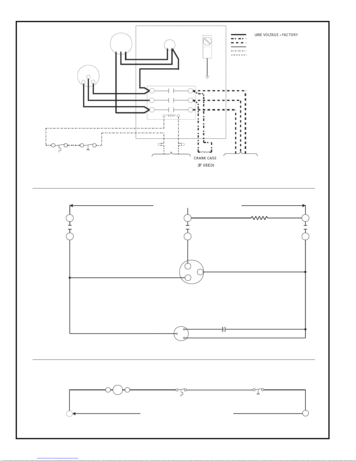
CONNECTION
DIAGRAM
COMP
T3
RED
FAN
YEL
YEL
BROWN
VIOLET
RED
T1
T2
T3
CAPACITOR
CONT ACTOR
FAN
MOTOR
BLACKBLACK
T2
T1
BRN
BLACKBLACK
EQUIPMENT GROUND
L1
L2
L3
BLK
YEL
BLK
LINEVOLTAGE - FACTORYLINE VOLTAGE - FACTORY
LINE VOLTAGE - FACTOR Y (IF USED)
LINE VOLTAGE - FIELD
LOWVOLTAGE - FACTOR Y
LOWVOLTAGE - FACTORY (IF USED)
LOWVOLTAGE - FIELD
NOTE:
REPLACEMENTWIRE MUST
BE THE SAME GAGE AND
INSULA TIONTHICKNESS,
105° APPLIANCE WIRING
MA TERIAL.
DISCHARGE
THERMOST AT
(IF USED)
SCHEMATIC
OF POWER
CIRCUIT
HIGH PRESS
SWITCH
(IF USED)
L3
COMPRESSOR
CONT ACTOR
T3
CONNECT TO“C” AND
“Y”TERMINALS OF
INDOOR CONTROL
CIRCUIT HAVING MIN.
40 VA, 24 VOLT N.E.C.40 VA, 24 VOLT N.E.C.
CLASS II TRANSFORMER.
CRANK CASECRANK CASE
OUTDOOR POWER SUPPLY
L2
T2
COMPRESSOR
MOTOR
FAN
MOTOR
T2
T3
HEATER
(IF USED)(IF USED)
T1
REFER TO RATING
PLATE FOR LINE
VOLTAGE 3 PHASE
POWER SUPPLY.USE
MINIMUM 75°C
COPPER WIRE ONLY.
CRANKCASE HEATER
(IF USED)
L1
T1
TYPICAL
SCHEMATIC
OF CONTROL
CIRCUIT
Y
Page 6 # 41718L098
R
COMPRESSOR
CONT ACTOR COIL
DISCHARGE THERMOSTAT
(IF USED)
THERMOSTAT TERMINALS
Figure 3
HIGH PRESSURE
SWITCH (IF USED)
PART NO.38942D005
C
Page 7
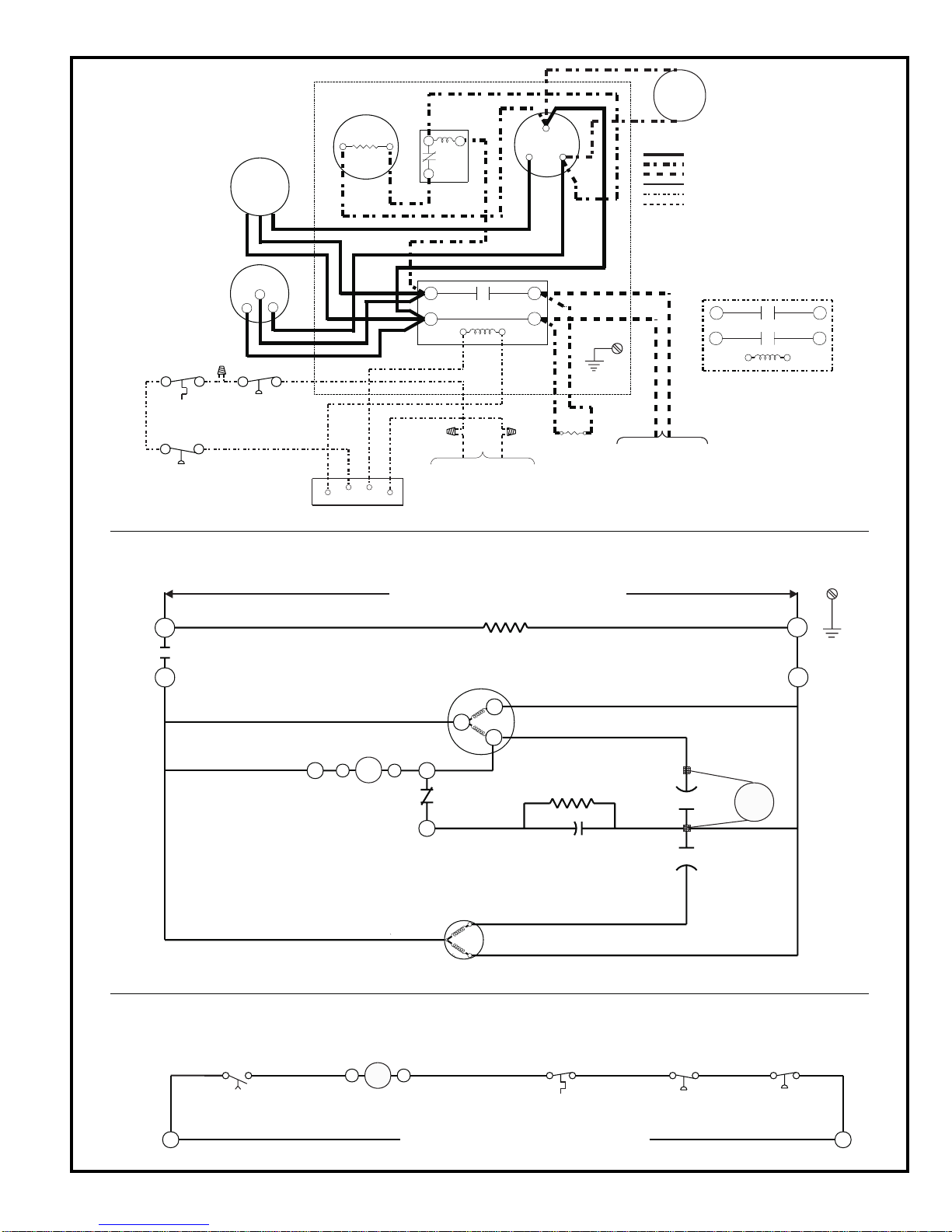
CONNECTION
DIAGRAM
DISCHARGE
THERMOSTAT
(IF USED)
LOW PRESSURE
SWITCH
(IF USED)
FAN
BROWN
BLK
VIOLET
COMP
C
S
R
R
BLK
RED
HIGH PRESSURE
SWITCH
(IF USED)
START CAP.
YEL
YEL
BLUE
LOAD
TIME DELAY RELAY
(IF USED)
RED
C
C
(IF USED)
BLUE
T'STAT
START RELAY
(IF USED)
2
5
1
RED
BLK
CONT ACTOR
T1
T2
YEL
YEL
CONNECT TO“C” AND
“Y”TERMINALS OF
INDOOR CONTROL
CIRCUIT HAVING MIN.
40 VA, 24 VOLT N.E.C.
CLASS II TRANSFORMER.
YEL
COM
HERM
FAN
COMP
RUN
CAP
L1
L2
CRANK CASE
HEATER
RED
BLK
BLK
(IF USED)
GROUND
SCREW
TO SINGLE PHASE
POWER SUPPLY PER
RATING PLATEWITH
MINIMUM 75°C COPPER
ONLY. CIRCUIT
WIRE
PROTECTION PER
RATING PLATE.
START
ASSIST
DEVICE
(IF USED)
LINE VOLTAGE - FACTORY
LINE VOLTAGE - FACTOR Y (IF USED)
LINE VOLTAGE - FIELD
LOWVOLTAGE - FACTOR Y
LOWVOLTAGE - FACTORY (IF USED)
LOWVOLTAGE - FIELD
NOTE:
IF ANY OF THE ORIGINAL
WIRE IS REPLACED,THE
SAME SIZE AND TYPEWIRE
MUST BE USED.
T1
T2
CONT ACTOR
L1
L2
ALT.
SCHEMATIC OF POWER CIRCUITSCHEMATIC OF POWER CIRCUIT
L1
COMPRESSOR
CONT A CTOR
T1
START RELAY
R
(IF USED)
OUTDOOR POWER SUPPLY
CRANKCASE HEATER
(IF USED)
R
COMPRESSOR
S
MOTOR
START CAPACITOR
(IF USED)
25
1
C
FAN
MOTOR
COMPRESSOR
RUN
CAP A CIT OR
START
ASSIST
DEVICE
(IF USED)
L2
T2
GROUND
SCREW
TYPICAL
SCHEMATIC
OF CONTROL
CIRCUIT
TDC
TIME DELAY
RELAY
(IF USED)
Y
# 41718L098 Page 7
R
COMPRESSOR
CONTACTOR COIL
DISCHARGE THERMOSTA T
(IF USED)
THERMOSTATTERMINALS
Figure 4
LOW PRESSURE
SWITCH
(IF USED)
HIGH PRESSURE
SWITCH
(IF USED)
PART NO.38602D008
C
Page 8

Limited Warranty
August 1, 1997
This warranty gives you specific legal rights and you may have other rights
which vary from state/province to state/province.
Armstrong Air Conditioning Inc. products are available under the following names: Air Ease, Armstrong Air, American Aire, Concord
Subject to the limitations stated in this warranty, we warrant to the first buyer for use the residential heating, cooling or heat pump unit,
when installed, operated and maintained as required by this warranty, to be free of defects in workmanship or material for a period of five
years (two years for commercial equipment) from the time of installation. We will replace any defective component without cost or
expense to you except for the costs of delivery and labor for removal and replacement of the defective component.
The SCU 12, 13 and E Series carry a 10 year compressor warranty. All other SCU Series air conditioners carry a 5 year compressor warranty.
The warranty period begins when the installation is complete and the product is ready to operate. You must be able to verify this date
whenever a warranty claim is made. Original bill of sale, installer’s invoice or other similar document will suffice. If the beginning date
cannot be verified, we will consider warranty coverage to begin six months after the date the product was shipped from our factory.
Implied warranties of merchantability or, to the extent applicable, fitness for a particular purpose are limited to five years, the same
duration as the basic limited written warranty provided herein. Some states/provinces do not allow limitations on how long an implied
warranty of merchantability or fitness lasts, so the above limitations or exclusions may not apply to you.
This written Limited Warranty is the only warranty made by the warrantor; this warranty is in lieu of and excludes all other warranties,
express or implied. The warrantor does not authorize any person to provide any other warranty or to assume for it any further obligation
in connection with the warranted product.
Warrantor: Armstrong Air Conditioning Inc., 421 Monroe St., Bellevue, OH 44811
Warranty Begins
Limitations on Implied Warranties
Only Warranty
What is NOT Covered
1. Cabinets or cabinet pieces.
2. Normal maintenance items such as filters, fan belts, fuses or other consumable items.
3. Damage caused by misuse, failure to maintain properly, accidents or acts of God.
4. External wiring, piping, venting or attachment of accessory products not integral to our product, including without limitation,
humidifier, air cleaner, vent damper, thermostat or other mechanical devices not manufactured by the warrantor.
5. Products that have been operated in a corrosive atmosphere where a concentration of acids, halogenated hydrocarbons or
other corrosive elements causes deterioration to metal surfaces or integral components. NOTE: Operation in a corrosive
atmosphere is considered abuse and voids this warranty.
6. Products that have NOT been installed in accordance with our published installation instructions, applicable local, state/
provincial or national codes, ACCA published standards.
7. Products that have NOT been installed by competent, qualified installers.
8. Products that have been moved from their original place of installation.
Warranty on Replacement Components
Any replacement component furnished by us will assume the remaining (unused) portion of the Limited Warranty.
Consequential Damages
The warrantor shall not be responsible for any consequential damages caused by any defect in the product. Some state/provinces do not
allow the exclusion or limitations of incidental or consequential damages, so the above limitation or exclusion may not apply to you.
NOTE: After the first year, in the event that a gas or oil heat exchanger is no longer being manufactured by the warrantor, the warrantor
will allow a credit equal to the then current wholesale price of an equivalent heat exchanger towards the purchase of a new Armstrong gas
or oil furnace.
This product must be installed, used and cared for in accordance with the instruction manual. You are responsible for required periodic
maintenance or service, such as changing or cleaning of air filters and lubrication or cleaning of components. Failure to properly install,
operate or maintain your unit voids this warranty.
Owner Record
Model # ________________________ Serial # _________________ Installation Date __________________
INSTALLED BY:
Dealer _____________________________________________________________________________________
Address ____________________________________________________________________________________
T elephone # ____________________________ License # _______________________________
Page 8 # 41718L098
 Loading...