

Page 1
lennoxemeia.com
RDF300.02
ARG71
Installation,
operating
and maintenance
RDF300.02 Remote control
ARG71 Installation plastic box
RDF300.02-IOM-0509-E
Page 2

Page 3
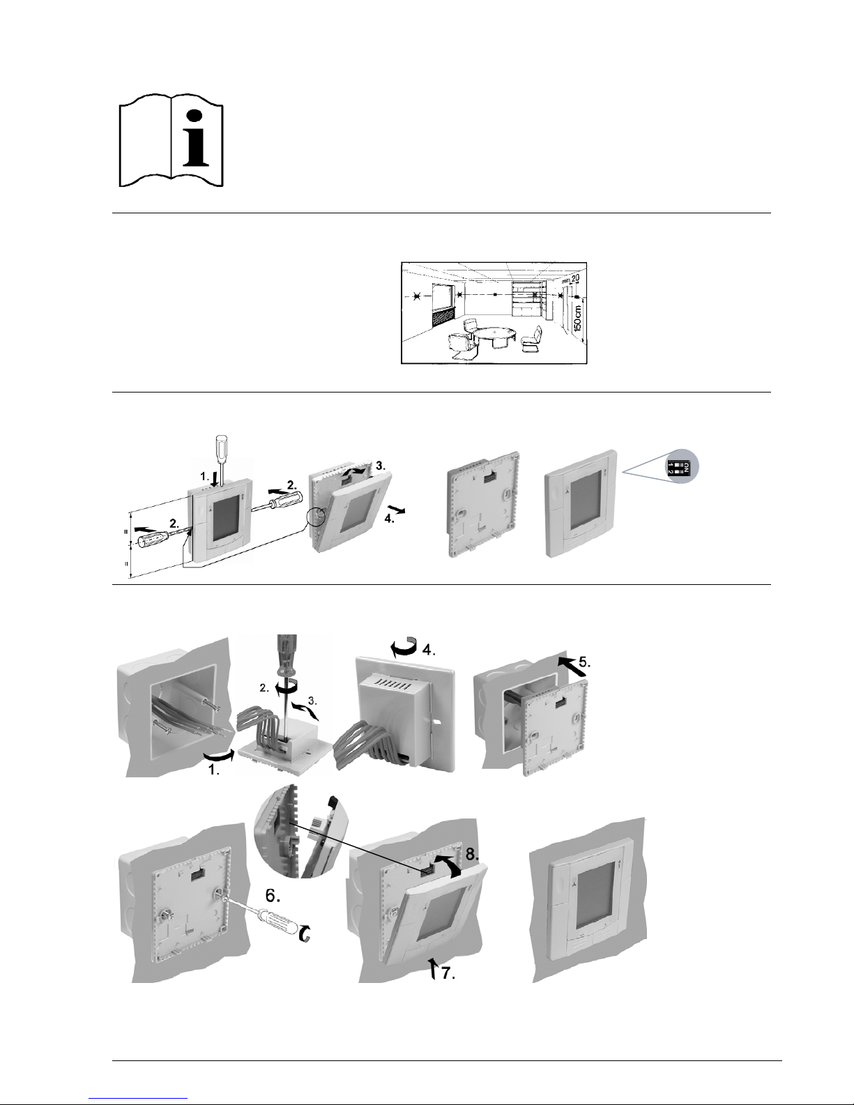
Mounting Location of Thermostat
Preparation and Deliverables
Semi-Flush-Mounting
RDF300...
RDF340...
RDF400...
5.
Page 4
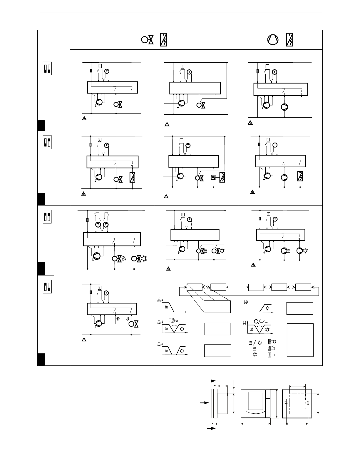
Wiring Diagram
Application
RDF300... / RDF400... RDF340 RDF300... / RDF400...
ON
1 2
2-pipe
en
L
N
10 A
L
N
Q1Q2Q3 Y11
Y21
AC 230 V
X1 M
X2
IIIIII
N1
B2
S1
M1
Y1
QAH11.1 +
ARG86.3
5(2)A
max.
5(2)A
max.
AC 230 V
G
G0
G
G0
Q1 Q2 Q3
Y10
Y20
AC 24V
X1 M
X2
IIIIII
N1
M1
L
N
L
Y1
max. ±1 mA
B2
S1
QAH11.1 +
ARG86.3
G - G0 AC 24 V
L - N AC 230 V
L
N
10 A
L
N
Q1Q2Q3 Y11
Y21
AC 230 V
X1 M
X2
IIIIII
N1
B2
S1
M1
C1
QAH11.1 +
ARG86.3
5(2)A
max.
5(2)A
max.
AC 230 V
ON
1 2
2-pipe & el. heater
en
L
N
10 A
L
N
Q1 Q2 Q3 Y11
Y21
AC 230 V
X1 M
X2
IIIIII
N1
B2
S1
M1
Y1
QAH11.1 +
ARG86.3
E1
5(2)A
max.
5(2)A
max.
5(2)A
max.
AC 230 V
G
G0
G
G0
Q1 Q2 Q3
Y10
Y20
AC 24V
X1 M
X2
IIIIII
N1
M1
L
N
L
Y1
max. ±1 mA
B2
S1
QAH11.1 +
ARG86.3
E1
max.
±
1 mA
YR
G - G0 AC 24 V
L - N AC 230 V
L
N
10 A
L
N
Q1 Q2 Q3 Y11
Y21
AC 230 V
X1 M
X2
IIIIII
N1
B2
S1
M1
QAH11.1 +
ARG86.3
E1
5(2)A
max.
5(2)A
max.
5(2)A
max.
AC 230 V
C1
ON
1 2
4-pipe
en
L
N
10 A
L
N
Q1 Q2 Q3 Y11
Y21
AC 230 V
X1 M
X2
IIIIII
N1
M1
Y1 Y2
5(2)A
max.
5(2)A
max.
5(2)A
max.
B2
S2
B1
S1
G
G0
G
G0
Q1 Q2 Q3
Y10
Y20
AC 24V
X1 M
X2
IIIIII
N1
M1
L
N
L
Y1 Y2
max. ±1 mA
max. ±1 mA
S1
QAH11.1
/ QAA32
G - G0 AC 24 V
L - N AC 230 V
L
N
10 A
L
N
Q1 Q2 Q3 Y11
Y21
AC 230 V
X1 M
X2
IIIIII
N1
S1
M1
5(2)A
max.
5(2)A
max.
5(2)A
max.
AC 230 V
QAH11.1
/ QAA32
C1
C2
ON
1 2
2-pipe, 3 position output
en
L
N
10 A
L
N
Q1 Q2 Q3 Y11
Y21
AC 230 V
X1 M
X2
IIIIII
N1
S1
M1
5(2)A
max.
5(2)A
max.
AC 230 V
QAH11.1 +
ARG86.3
Y1
T °C
T °C
T °C
P01 P02 P13
+
-
-
+
P14
-
+
P12
+
-
P01=0
+-
P01=1
P01=2
P01=3
P01=4
T
T °C
X2
M
T
QAH11.1
T °C
X2
M
X2
M
Legend: Dimensions
N1 RDF3xx / RD
M1 3 Steps-Fan
Y1,Y2 Valve
C1,C2 Compressor
E1 Electro heater
S1 Operating mode switch-over
contact (e.g. k
ey card
YR Current valve
B2
Heat/cool changeover sensor
View A
Section B - B
A
B
B
60 mm
62 mm
49 mm
86 mm
62 mm
44 mm
5 mm
14 mm
86 mm
10 mm
Page 5

ARG 71 CASES ASSEMBLY INSTRUCTIONS
Easy installation
Characteristics/functions
This controller is very easy to install : (1) connexion, (2) assembly and screwing, (3) fitting together
of regulation and displaying element without any risk of supplying cable handing.
Important:
Please check that controller fits to the case delivered. Controller dimensions (53 mm (L) x
68 mm (H) x 46 mm (P)) request adapted case with a 60.3 mm fixing distance.
(1) (2) (3)
Page 6

Technical data
RDF300 / RDF400:
Operating voltage
AC 230 V +10/-15%, 50/60 Hz
Output rating
Heating/cooling (relay)
3-speed fan (relay)
Max. 5 (2) A
Max. 5 (2) A
RDF340:
Operating voltage
AC 24 V +/-20 %, 50/60 Hz
Output rating
Heating/cooling (DC 0..10 V)
3-speed fan (relay)
Max. 1 mA
Max. 5 (2) A @ AC 230 V
RDU340:
Operating voltage
AC 24 V +/-20 %, 50/60 Hz
Output rating
Heating/cooling (DC 0..10 V)
Electric reheater (relay)
DC 0...10 V, max. 1 mA
Max. 5 (2) A @ AC 230 V
Input
Multifunctional X1, X2 NTC cable sensor like QAH11 / switch
Setpoint setting range 5...40 °C in 0.5 °C increments
Control algorithm 2P / PI (P)
Environmental conditions
Temperature
Relative humidity
0...50 °C
<95%
Mounting type Semi flush-mount, fixing centers 60.3 mm
Dimension (visible part) 86mm x 86mm x 14 mm
Mounting type Semi flush-mount for mounting into recessed
rectangular conduit box with fixing centers 60.3 mm
Dimensions
60.3mm
Page 7

ARG71 – Installation plastic box for all RDF semi flush-mounted
room temperature controllers
Main features:
• Size: 75 mm x 75 mm x 51 mm with
fixing centers 60.3 mm
• For installation of all semi flushmount room temperature controllers
• Conformant to BSI standard
BS4662, EN 50086-2-1, IEC/670.
Page 8

Operating Instructions
RDF300…, RDF340…,
RDU340…
RDF/RDU… – the temperature controller that allows you to set the ideal room temperature you want. The controller
provides comfort mode, energy saving mode and standby. The fan operates either in automatic mode or at the selected
speed when using manual mode. You can either rely on the factory settings or make adjustments that suit your individual
needs.
Are your rooms too warm or too cold?
+ -
Pressing + or - allows you to increase or decrease the current room temperature setpoint for comfort mode.
The maximum setting range is from 5...40 °C, unless it is limited by parameters P09 and P10.
Do you want to change from heating to cooling mode?
/
The changeover between cooling and heating is done either automatically by a
heating / cooling changeover sensor or a remote changeover switch, or manually
by pressing the operating mode button
. If the controller is configured cooling
only or heating only, no changeover is possible (see parameter P01)
By automatic changeover or continuous heating/cooling:
Display shows that heating valve is open
Display shows that cooling valve is open
By manual changeover:
Display shows that controller is in heating mode
Display shows that controller is in cooling mode
Do you want to change the fan mode?
Press the button until you have selected the desired fan mode.
In automatic mode, the fan speed is automatically selected by the controller and
depends on the setpoint and the actual room temperature. When the room
temperature has reached the setpoint, the fan remains in fan speed low (factory
setting)
In manual mode the fan operates independently and always runs at the same
speed: Low, medium or high.
Low fan speed
Medium fan speed
High fan speed
By a single-speed fan, the mode can be changed between
and .
Do you want to set your controller to standby?
Press the operating mode button several times until the display shows the
symbol to indicate that standby is selected.
In standby
, only frost protection is active (factory setting = 8˚C), unless your
HVAC installer has adjusted the factory settings.
Changes by installer Frost protection: ........... ˚C
Heat protection: ........... ˚C
Do you want to change to Energy saving mode?
The controller can be set in energy saving mode either via pressing the operating
mode button
if enabled (see parameter P02), or via an external contact such
as window switch, key card switch etc.
If the external contact is activated the controller changes from comfort mode or
standby to energy saving mode. Any operation by the user has no influence.
In energy saving mode the automatic fan speed is active.
Note: If the controller is configured for manual heating / cooling changeover, the
Energy saving mode can not be selected via operating mode button
.
Display
Operation and Settings
Automatic fan
Low fan speed
Medium fan speed
High fan speed
Ke
yp
ad locked
Indication of alarm*
Condensation in the room*
Cooling demand / mode
Heating demand / mode
Electrical heater active
Standby
Comfort mode
Energy Saving mode
Measured room temperature,
setpoints and parameters
Symbol when actual room
temperature displa
y
ed
Current time of the day or
additional user information
Adjusting fan mode
- Automatic fan ( )
- Manual fan (
)
No fan available on RDU…!
Adjusting operating mode
- Standby ( )
- Comfort mode (
)
- Energy saving mode (
)*
or by a system with manual changeover
- Standby (
)
- Comfort heating (
)
- Comfort cooling (
)
Colder / Warme
r
* if configured by your HVAC installer
Page 9

Do you want to lock the keypad?
Reminder clean filter!
Alarm !
Commissioning (by qualified HVAC installer)
To adapt the controller to your system and optimize the control performance, a number of
control parameters can be adjusted. This can also be made during operation without
opening the controller.
Control sequence
Recalibrating the sensor
Energy saving mode
If you want to change the factory-set temperature setpoints (15 °C for heating
and 30 °C for cooling), the parameter P11 and P12 need to be adjusted.
Important: The setpoint of energy saving mode can be set to OFF; this
means that the controller is then not active! Risk of frost, i.e. no protective
heating or cooling function.
Control parameter
If you want to change the control parameters, proceed as follows:
+ / -
+ / -
+ / -
+ / -
1. Set the controller to standby
2. Press - and + simultaneously for a minimum of 3 seconds.
Release them and, within 2 seconds, press the + again for 3 seconds. The display will show “P01”.
3. Select the required parameter by repeatedly pressing the + or – button.
4. Press + and – simultaneously, the current value of the selected parameter starts to flash, which can be
changed by repeatedly pressing + or -.
5. By pressing + and - simultaneously again the next parameter will be displayed.
6. If you wish to display and change additional parameters, repeat steps 3 through 5.
7. 10 seconds after the last display or setting, all changes are stored and the controller will leave parameter enter
mode.
Please record all changes you make! (all temperature settings can be made in increments of 0.5 K)
If the keypad lock function is enabled by parameter P14, then pressing 7
seconds on the operating mode button
, the keypad will be locked or
unlocked respectively.
If “Auto lock” is configured, then the controller will automatically lock the
keypad after 30 seconds of the last adjustment.
FIL
This message reminds you to clean the filter on your HVAC equipment.
It will appear after …………….….. “fan operating hours” and disappear
when the controller is set to standby (
). This reminder must be configured
by your HVAC installer.
AL1
AL2
This alarm message tells you an external alarm has occurred:
AL1 :……………………………..….
AL2 :………………………………….
The alarms are configured by your HVAC installer
The controller can be used in systems either for heating only or cooling only,
manually selection of heating or cooling, or automatic heating / cooling
changeover. Depending on the selected application, the relevant modes are
available and can be adjusted by commissioning parameter P01 if needed.
The factory setting for 2-pipe and single duct application is “Cooling only”,
and for 4 pipe application “Heating and Cooling”
If the room temperature displayed by the controller does not agree with the
temperature effectively measured, the temperature sensor can be
recalibrated. With parameter P05 the temperature can be adjusted by + or –
0.5 °C up to a maximum of + / - 3 °C.
Parameter
Controller’s parameter factory settings: Setting range
RDF3…
RDU340.
P01 Control sequence
2-pipe…: [0…3]
1 (Cool only)
4-pipe:. [2…4]
4 (Heat&Cool)
0:= Heating only
1:= Cooling only
2:= Manual H or C
3:= Auto Changeover
4:= Heating & cooling
P02 Mode selection by user operating mode button 1 (Stb, Comf) 1 = Stb, Comf
2 = Stb, Comf, Eco
P04 Selection of °C or °F °C °C or °F
P05 Sensor calibration 0.0 K – 3 ... +3 K
P06 Standard temperature display 0 (Room temp.) 0:= Room temp
1:= Setpoint
P07 Additional user info 0 (no display) 0:= no display
1:= Temp in °C + °F
P08 Comfort basic setpoint 21 °C 5 ... 40 °C
P09 Minimum setpoint limitation in Comfort (Wmin
Comf
) 5 °C 5 ... 40 °C
P10 Maximum setpoint limitation in Comfort (Wmax
Comf
) 35 °C 5 ... 40 °C
P11 Setpoint of heating in Energy Saving (Wheat
Eco
) 15 °C OFF, 5 °C…Wcool
Eco
P12 Setpoint of cooling in Energy Saving 30 °C OFF, Wheat
Eco
…40°C
P13 Electrical heater in cooling mode ON OFF:= disabled
ON:= enabled
P14 Keypad lock
(Pressing 7 seconds on the operating mode button , the
keypad will be locked or unlocked respectively)
0 (Disabled) 0:= Disabled
1:= Auto lock
2:= Manual lock
P01 P02 P08 P13
+-+
--
+
3057z03
P14
-
+
P12
+-
Page 10

Page 11

Page 12

lennoxemeia.com
+7 495 626 56 53
+34 902 533 920
+38 044 585 59 10
+44 1604 669 100
+ 32 3 633 3045
+33 1 64 76 23 23
+49 (0) 40 589 6235 0
+ 39 02 495 26 200
+ 31 332 471 800
+48 22 58 48 610
+351 229 066 050
LENNOX DISTRIBUTION
+33 4 72 23 20 00
RUSSIA
SPAIN
UKRAINE
UNITED KINGDOM AND IRELAND
BELGIUM AND LUXEMBOURG
FRANCE
GERMANY
ITALY
NETHERLANDS
POLAND
PORTUGAL
SALES OFFICES :
OTHER COUNTRIES :
Due to Lennox’s ongoing commitment to quality, the specifi cations,
ratings and dimensions are subject to change without notice and
without incurring liability.
Improper installation, adjustment, alteration, service or
maintenance can cause property damage or personal injury.
Installation and service must be performed by a qualifi ed installer
and servicing agency
RDF300.02-IOM-0509-E
 Loading...