

Lennox PWC183, PWC18E4.8, PWC18E9.2, PWC242, PWC18E10.7 Installation And Maintenance Instructions Manual
...Page 1
INSTALLATION AND
MAINTENANCE INSTRUCTIONS
PWC Series "Magic-Pak"
Self-Contained Heat Pump
[ WARNING
Improper installation, adjustment, alteration, service or maintenance can cause injury
or property damage. Refer to this manual. For assistance or additional information,
consult a qualified installer or service agency.
I _'WARNING I
For your safety, do not store or use gasoline or
other flammable vapors and liquids in the
vicinity of this or any other appliance. Such
actions could result in property damage, per-
sonal injury or death.
Installation and servicing of air conditioning
equipment can be hazardous due to internal
refrigerant pressure and live electrical compo-
nents. Only trained and qualified service
personnel should install or service this equip-
ment. Installation and service performed by
unqualified persons can result in property
damage, personal injury or death.
] A CAUTION I
These units are not approved for mobile home
applications. Such use could result in prop-
erty damage, p_rsonal injury or death.
TABLE OF CONTENTS
INSTALLATION ....................................... 2
OPERATION .......................................... 5
MAINTENANCE ..................................... 6
WIRING DIAGRAMS .............................. 7
WARRANTY ......................................... 10
ManufacturedBy
A.A.C.
A Lennox International Company
421 MonroeStreet
Bellevue,OH 44811
IIIIIIIIIIII)llllllllllllllllllllllllll}lilllllll
I A CAUTION [
The installation of this appliance must conform to the requirements of the National Fire Protection Associa-
tion; the National Electrical Code, ANSl/NFPA No. 70 (latest edition) in the United States; the Canadian
Electrical Code Part 1, CSA 22.1 (latest edition) in Canada; and any state or provincial laws or local ordi-
nances. Local authorities having jurisdiction should be consulted before installation is made. Such appli-
cable regulations or requirements take precedence over the general instructions in this manual.
Save these instructions for future reference
Page 2
INSTALLATION
General
=.seinstructions explain the recommended method of
,llation of the PWC heat pump unit and associated
e_uctricalwiring.
the unit inside the carton ifthe carton isdamaged. File a
cfaimwith the transportation company. If any damages
are discovered and reported to the carrier DO NOT
INSTALL THE UNIT, as claim may be denied.
Check the unit rating p'late to confirm specifications
are as ordered.
This unit is designed and approved for use as a self-
contained air to air heat pump system.
These instructions, and any instructions packaged with
mating components and/or accessories, should be carefully
read prior to beginning installation. Note particularly any
CAUTIONS or WARNINGS in these instructions and all la-
bels on the units.
These instructions are intended as a general guide only,
for use by qualified personnel and do not supersede any
national or local codes in any way. Compliance with all
local, state, provincial or national codes pertaining to this
type of equipment should be determined priorto installa-
tion.
Inspection
Upon receipt of equipment, carefully inspect itfor possible
shipping damage. If damage is found, it should be noted
on the carrier's freight bill. Take special care to examine
Location
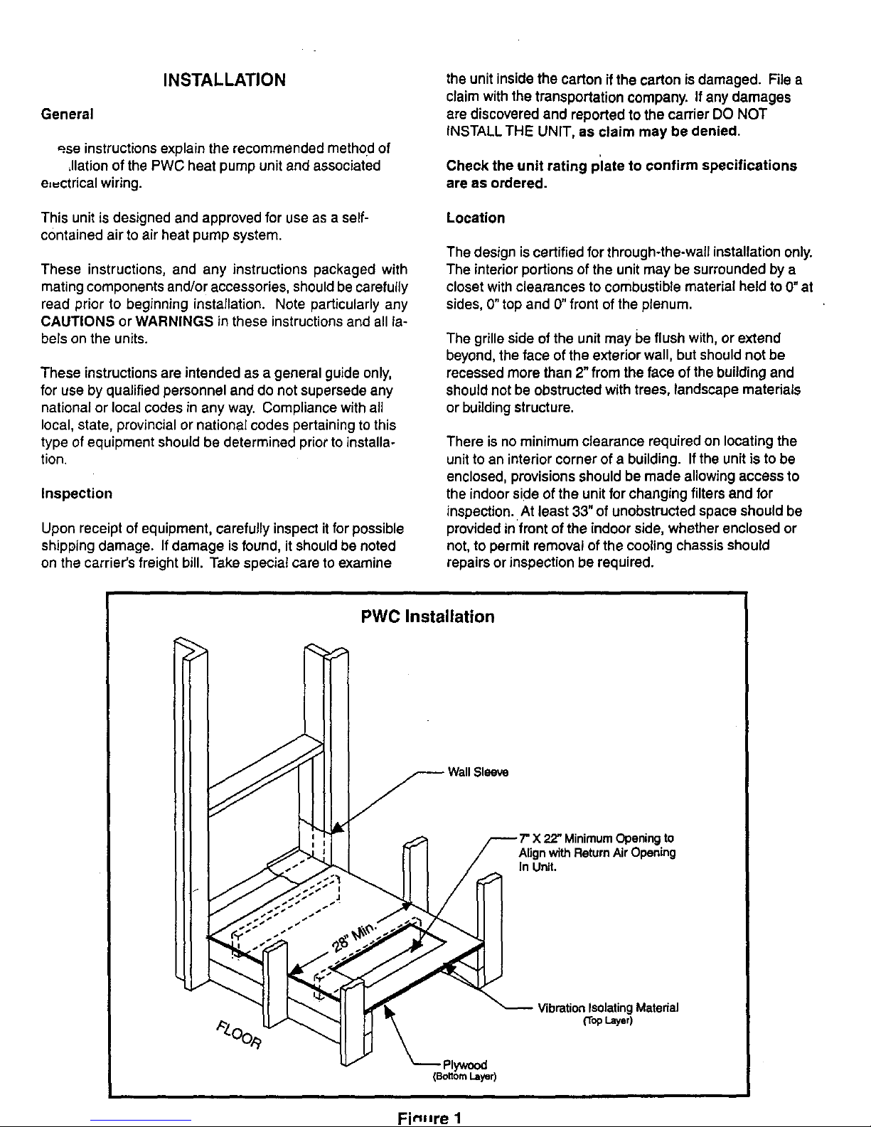
The design is certified for through-the-wall installation only.
The interior portions of the unit may be surrounded by a
closet with clearances to combustible material held to 0" at
sides, 0" top and 0" front ofthe plenum.
The grille side of the unit may be flush with, or extend
beyond, the face of the exterior wall, but should not be
recessed more than 2" from the face of the building and
should not be obstructed with trees, landscape materials
or building structure.
There is no minimum clearance required on locating the
unit to an interior corner of a building. If the unit is to be
enclosed, provisions should be made allowing access to
the indoor side of the unit for changing filters and for
inspection. At least 33" of unobstructed space should be
provided infront of the indoor side, whether enclosed or
not, to permit removal of the cooling chassis should
repairs or inspection be required.
PWCInstallation
Sleeve
F MinimumOpening to
Align with Return Air Opening
In Unit.
VibrationIsolating Matedal
{TopLayer)
Fin-re 1
Page 3
If the unitis installed in a residential garage, it must be
located or protected to avoid physical damage by vehicles.
The unit must be installed so that no electrical compo-
nents are exposed to water.
I
[A CAUT,ON]
This unit must be installed level to allow for
proper drainage of the chassis base pan and
unit drain pan.
Installing With a Wall Sleeve
[ _, CAUTION l
The sleeve is not intended as the sole support
for the unit. An additional support must be
provided near the return opening on the unit
for adequate support. The use of vibration
isolation material between the unit and the
support is recommended.
Refer to the installation instructions packed with the wall
sleeve and Figure 1 for guidance in assembly and mount-
ing using a wall sleeve.
Make sure the gaskets attached to the sleeve are not
damaged.
Seal the space between the wall sleeve and-the building
opening with non-hardening caulking compound. The seal
must be weathertight to prevent entrance of moisture and
water into the building.
Assure that the unit is completely seated against the
gaskets on the wall sleeve.
Installing Without a Wall Sleeve
Refer to the following directions and Figure I for guidance
in installing the unit without a wall sleeve:
.
Measure the size of the unit and provide an opening in
an outside wall that will accept the unit. Local ordi-
nances may require a steel lintel to support the wall
above the opening. The opening must be square in all
4 corners.
,
Position the unit so that the grilles on the outside face
of the unit are flush or extend beyond the face of the
exterior wall, but not recessed more than 2" from the
face of the building. Provide a support under the
unit, inside the building. Make sure that the inside
support does not block the return air. The unit should
be installed level
.
Seal the space between the unit and building opening
using a non-hardening caulking compound. The seal
mustbe weathertight to prevent entrance of moisture
and water into the building. Make sure the drain holes
in the base are not plugged withcaulking,
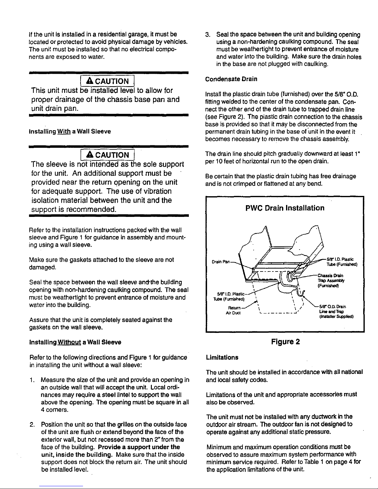
Condensate Drain
Install the plastic drain tube (furnished) over the 5/8" O.D.
fitting welded to the center ofthe condensate pan. Con-
nect the other end of the drain tube to trapped drain line
(see Figure 2). The plastic drain connection to the chassis
base is provided so that it may be disconnected from the
permanent drain tubing in the base of unitin the event it
becomes necessary to remove the chassis assetnbly.
The drain line should pitch gradually downward at least 1"
per 10feet of horizontal run to the open drain.
Be certain that the plastic drain tubing has free drainage
and is not crimped or flattened at any bend.
PWC Drain Installation
Drain Pan_
Figure 2
Limitations
The unit should be installed in accordance with all national
and local safety codes.
Limitations of the unit and appropriate accessories must
also be observed.
The unit must not be installed with any ductwork in the
outdoor air stream. The outdoor fan is not designed to
operate against any additional static pressure.
Minimum and maximum operation conditions must be
observed to assure maximum system performance with
minimum service required. Refer to Table 1 onpage 4 for
the application limitations of the unit.
Page 4
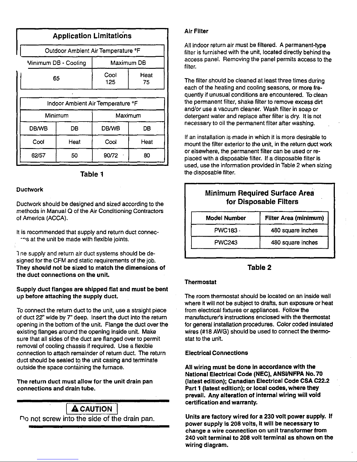
Application Limitations AirFilter
Outdoor Ambient Air Temperature °F
Minimum DB - Cooling Maximum DB
Cool Heat
65
125 75
Indoor Ambient Air Temperature °F I
Minimum Maximum
DB/WB DB DB,_VB DB
Cool Heat Cool Heat
62/57 50 90/72 80
Table t
Ductwork
Ductwork should be designed and sized according to the
methods in Manual Q of the Air Conditioning Contractors
of America (ACCA).
It is recommended that supply and return duct connec-
-'_s at the unit be made with flexible joints.
1ne supply and return air duct systems should be de-
signed for the CFM and static requirements of the job.
They should not be sized to match the dimensions of
the duct connections on the unit.
Supply duct flanges are shipped flat and must be bent
up before attaching the supply duct.
To connect the return duct to the unit, use a straight piece
of duct 22" wide by 7" deep. Insert the duct into the return
opening in the bottom of the unit. Flange the duct over the
existing flanges around the opening inside unit. Make
sure that all sides of the duct are flanged over to permit
removal of cooling chassis if required. Use a flexible
connection to attach remainder of return duct. The return
duct should be sealed to the unit casing and terminate
outside the space contai_ningthe furnace.
The return duct must allow for the unit drain pan
connections and drain tube.
[ ACAUTION J
no not screw intothe side of the drain pan.
All indoor return air must be filtered. A permanent-type
filter is furnished with the unit, located directly behind the
access panel. Removing the panel permits access to the
filter.
The filter should be cleaned at least three times during
each of the heating and cooling seasons, or more fre-
quently if unusual conditions are encountered. To clean
the permanent filter, shake filter to remove excess dirt
and/or use a vacuum cleaner. Wash filter in soap or
detergent water and replace after filter is dry. It is not
necessary to oil the permanent filter after washing.
If an installation is.made in which it is more desirable to
mount the filter exterior to the unit, in the return duct work
or elsewhere, the permanent filter can be used or re-
placed with a disposable filter. If a disposable filter is
used, use the information provided in Table 2 when sizing
the disposable filter.
Minimum Required Surface Area
for Disposable Filters
Model Number Filter Area (minimum)
PWC183 - 480 square inches
PWC24,3 480 square inches
Table 2
Thermostat
The room thermostat should be located on an inside wall
where it will not be subject to drafts, sun exposure or heat
from electrical fixtures or appliances. Follow the
manufacturer's instructions enclosed withthe thermostat
for general installation procedures. Color coded insulated
wires (#18 AWG) should be used to connect the thermo-
stat to the unit.
Electrical Connections
All wiring must be done In accordance with the
National Electrical Code (NEC), ANSl/NFPA No. 70
(latest edition); Canadian Electrical Code CSA C22.2
Part I (latest edition); or local codes, where they
prevail. Any alteration of internal wiring will void
certification and warranty.
Units are factory wired for a 230 volt power supply. If
power supply is 208 volts, it will be necessary to
change a wire connection on unit transformer from
240 volt terminal to 208 volt terminal as shown on the
wiring diagram.
Page 5
Usewiringwithatemperaturelimitation of 75 =C mini-
mum. Run the 208 or 230 volt, 60 hertz electric power
supply through a fused disconnect switch to the control
box of the unit and connect as shown in the wiring dia-
gram located onthe inside of the control access panel.
The unit must be electrically grounded in accordance with
local codes or, in the absence of local codes, with the
National Electrical Code ANSI/NFPA No. 70 (latest edition)
or CSA C22.2 Part 1 (latest edition).
Power supply to the unit must be NEC Class 1 and must
comply with all applicable codes. A fused disconnect
switch should be field provided for the unit. The switch
must be separate from all other circuits. If any of the wire
supplied with the unit must be replaced, replacement wire
must be of the type shown on the wiring diagram.
Electrical wiring must be sized to minimum circuit
ampacity marked on the unit. Use copper conductors
only. Each unitmust be wired with a separate branch
circuit and be properly fused.
OPERATION
Sequence of Operation
Cooling
When the thermostat is in the cooling mode, the O circuit
is powered which energizes the reversing valve. Upon
cooling demand, the thermostat closes circuit R toY and
G. Closing R to Y closes the unit contactor, starting the
compressor and outdoor fan. The thermostat automati-
cally closes R to G circuit which also brings on the indoor
blower at the same time. Upon satisfying cooling demand,
the thermostat will open the above circuits and open the
main contactor, stopping the compressor and outdoor fan.
If the unit is equipped with a time delay, the blower will
continue to operate for 90 seconds which improves
system efficiency.
Heating
Upon heating demand, the thermostat closes circuit R to
Y, which closes the unit contactor, starting the compressor
and outdoor fan. The reversing valve is not energized in
the heating mode. -The thermostat again automatically
brings on the indoor fan at the same time. The second
stage of the thermostat closes circuit R to W, which closes
the unit sequencers, bringing the auxiliary electric heat on.
Upon satisfying heating demand, the thermostat opens
the above circuits and stops unit operation.
Defrost Cycle
Ifthe outdoor ambient conditions are such that frost forms
on the outdoor coil, the defrost control monitors the need
for and initiates and terminates defrost cycles as neces-
sary to maintain system performance. The defrost control
is time/temperature initiated and temperature terminated
with a maximum defrost time (time-out) of 10 minutes.
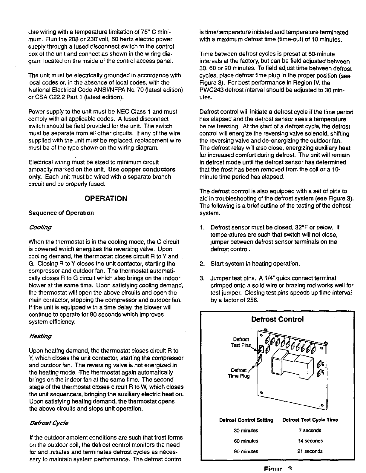
Time between defrost cycles is preset at 60ominute
intervals at the factory, but can be field adjusted between
30, 60 or 90 minutes. To field adjust time between defrost
cycles, place defrost time plug in the proper position (see
Figure 3). For best performance in Region IV, the
PWC243 defrost interval should be adjusted to 30 min-
utes.
Defrost controlwill initiate a defrost cycle ifthe time period
has elapsed and the defrost sensor sees a temperature
below freezing. At the start of a defrost cycle, the defrost
control will energize the reversing valve solenoid, shifting
the reversing valve and de-energizing the outdoor fan.
The defrost relay will also close, energizing auxiliary heat
for increased comfort during defrost. The unit will remain
in defrost mode until the defrost sensor has determined
that the frost has been removed from the coil or a 10-
minute time period has elapsed.
The defrost control is also equipped with a setof pins to
aid in troubleshooting of the defrost system (see Figure 3).
The following is a brief outline of the testing of the defrost
system.
. Defrost sensor must be closed, 32°F or below. If
temperatures are such that switch will not close,
jumper between defrost sensor terminals on the
defrost control,
2. Start system in heating operation.
.
Jumper test pins, A 1/4" quick connect terminal
crimped onto a solid wire or brazing rod works well for
test jumper. Closing test pins speeds up time interval
by a factor of 256.
Defrost
TestPins.,,,=i
Defro=/
TimePlug
Defrost Control
Defrost Control Setting Defrost Test Cycle Time
30 minutes 7 seconds
60 minutes 14 seconds
90 minutes 21 seconds
FinHr
Page 6
After closing test pins and appropriate cycle time has
elapsed, the reversing valve should shift to defrost mode
and the outdoor fan should stop. After 2 seconds of
defrost operation, the reversing valve should shift back to
",tingoperation and the outdoor fan should start.
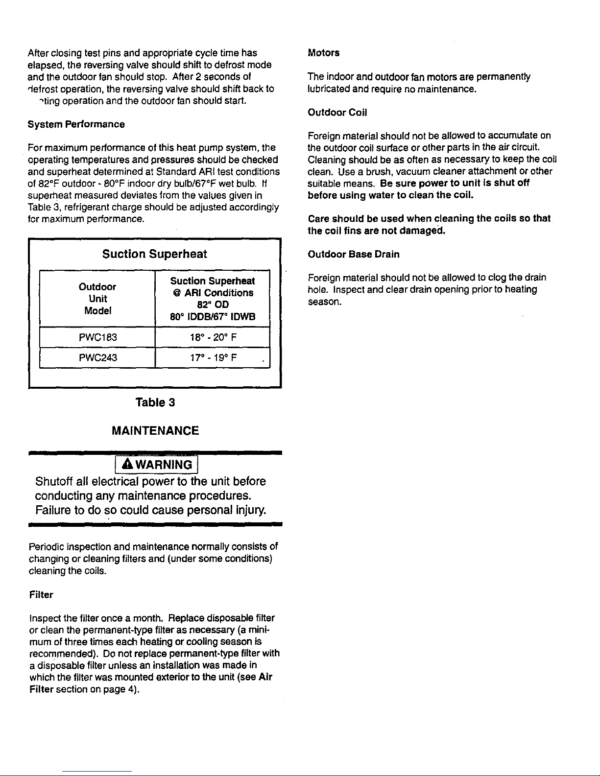
System Performance
For maximum performance of this heat pump system, the
operating temperatures and pressures should be checked
and superheat determined at Standard ARI test conditions
of 82°F outdoor - 80°F indoor dry bulb/67°F wet bulb. If
superheat measured deviates from the values given in
Table 3, refrigerant charge should be adjusted accordingly
for maximum performance.
Suction Superheat
Suction Superheat
Outdoor
@ ARI Conditions
Unit
82 ° OD
Model
80° IDDB/67 ° IDWB
PWC183 18° - 20° F
PWC243 17° - 19° F
Motors
The indoor and outdoor fan motors are permanently
lubricated and require no maintenance.
Outdoor Coil
Foreign material should not be allowed to accumulate on
the outdoor coil surface or other parts in the air circuit.
Cleaning should be as often as necessary to keep the coil
clean. Use a brush, vacuum cleaner attachment or other
suitable means. Be sure power to unit is shut off
before using water to clean the coil.
Care should be used when cleaning the coils so that
the coil fins are not damaged.
Outdoor Base Drain
Foreign material should not be allowed to clogthe drain
hole. inspect and clear drain opening priorto heating
season.
Table 3
MAINTENANCE
Shutoff all electrical power to the unit before
conducting any maintenance procedures.
Failure to do so could cause personal injury.
Periodic inspection and maintenance normally consists of
changing or cleaning filters and (under some conditions)
cleaning the coils.
Filter
Inspect the filter once a month. Replace disposable filter
or clean the permanent-type filter as necessary (a mini-
mum ofthree times each heating or cooling season is
recommended). Do not replace permanent-type filter with
a disposable filter unless an installation was made in
which the filter was mounted exterior to the unit (see Air
Filter section on page 4).
Page 7
208/230-1-60
POWERSUPPLYWITHMIN.
75"CCOPPERWIRE
I CIRCUIT1I I (lo_cO_L'qCIRCUIT2I
•; ..; : :
P_D
BLACK
LOWER MOTORvloI_rr
RED
UNE VOLTAGE-FACTORY
UNE VOLTAGE-RELD
........ UNE VOLTAGE-RELD (IF USED)
LOW VOLTAGE-FACTORY
.......... LOW VOLTAGE-FIELD
7 AND 10 PWC ONLY
I
BLOWER
(
M1
CAPACr_R-RUN
BLUE
NOTE:
IF ANY OF THE ORIGINAL
WIRES ARE REP_, THE
SAME SIZE AND TYPE WIRE
MUST BE USED.
CONNECTOR
CONDENSER FAN
BLACK
BROWN
REV
VALVE
©
DEFROST
SENSOR
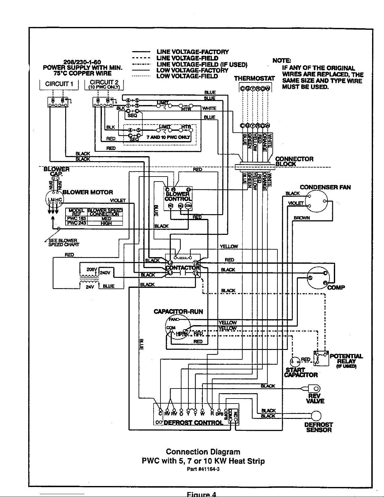
Connection Diagram
PWC with 5, 7 or 10 KW Heat Strip
Part #41164-3
Fin.r== 4
Page 8
208/230-1-60
:OWER SUPPLY WITH MIN.
75"C COPPER WIRE
I CIRCUIT 1 I CIRCUIT 2
: i : :
: •
RED
F_
UNE VOLTAGE-FACTORY
..... LINE VOLTAGE-RELD
........ LINE VOLTAGE-FIELD (IF USED)
LOW VOLTAGE-FACTORY
.......... LOW VOLTAGE-R ELD
BLUE
UMrT
BLOWER
m
NT
CAPACITOR-RUN
RED
¥
I
DEFROST
NOTE:
IF ANY OF THE ORIGINAL
WIRES ARE REPLACED, THE
SAME SIZE AND TYPE WIRE
MUST BE USED.
CONNECTOR
BLOCK
CONDENSER FAN
E_CK
REV
VALVE
O
I
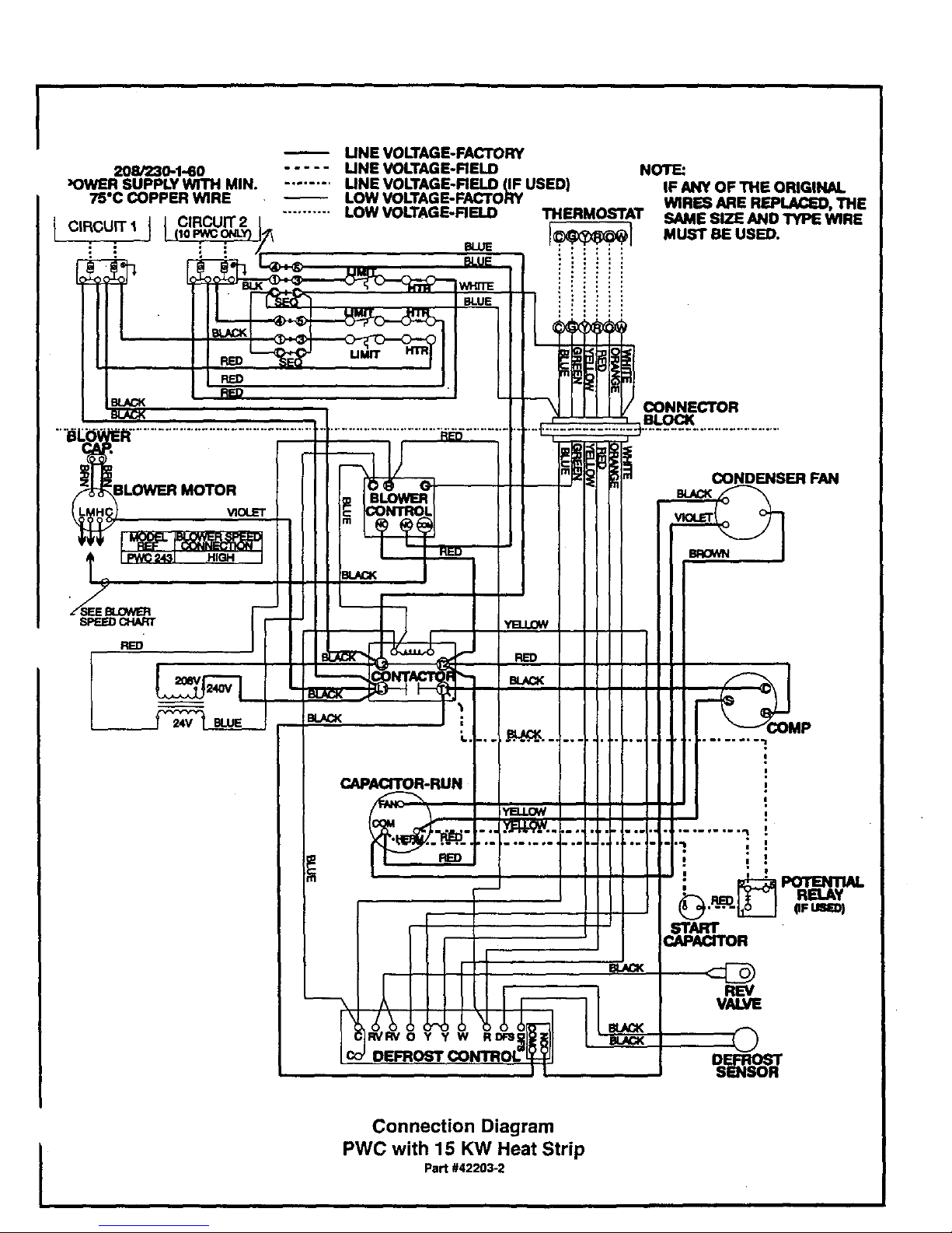
Connection Diagram
PWC with 15 KW Heat Strip
Part #42203-2
Page 9
208/230-1-60
POWER SUPPLY WITH MIN.
75"C COPPER WIRE
LINE VOLTAGE-FACTORY
..... UNE VOLTAGE-FIELD
........ UNE VOLTAGE-FIELD (IF USED)
LOWVOLTAGE-FACTORY THERMOSTAT
.......... LOW VOLTAGE-FIELD
NOTE:
IF ANY OF THE ORIGINAL
WIRES ARE REPLACED, THE
SAME SIZE AND TYPE WIRE
MUST BE USED.
BLOWER MOTOR
BLOWER
I_)
RED
_-RUN
RE)
CONDENSER FAN
BROWN
: : °
!
, POTENTIAL
RELAY
pFUSe_
I
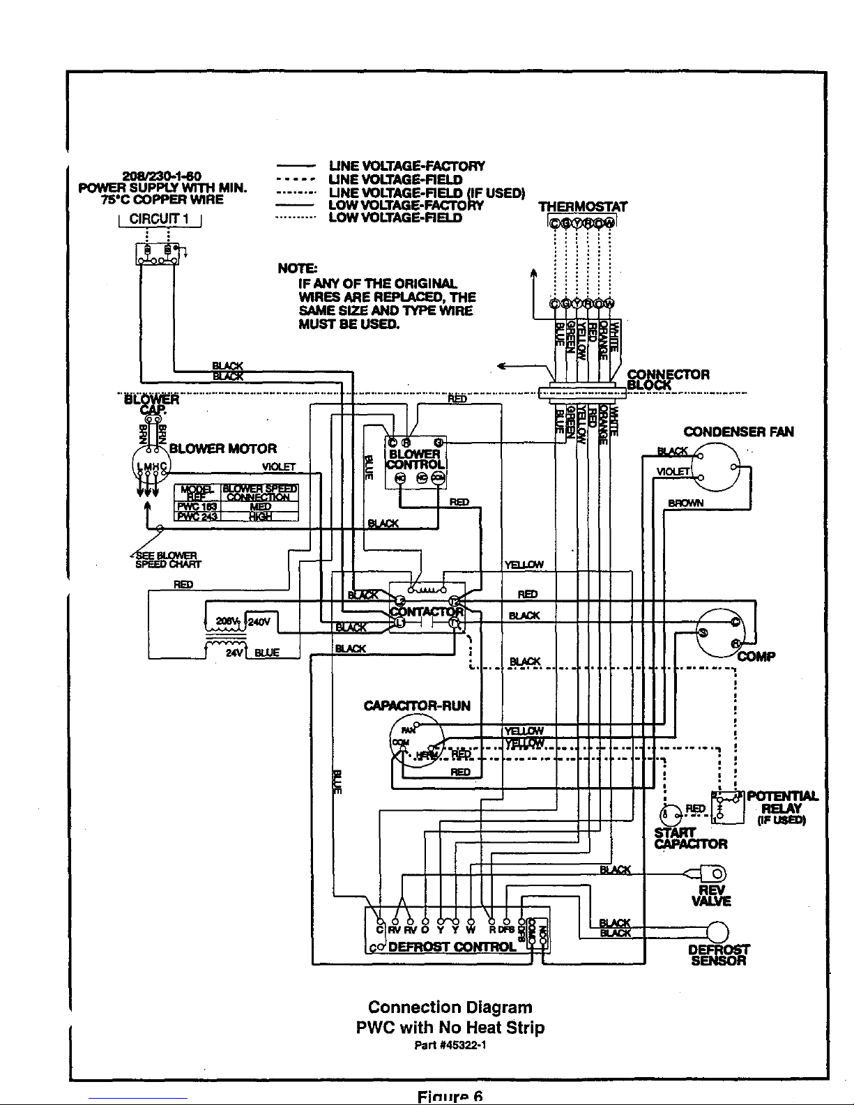
Connection Diagram
PWC with No Heat Strip
Part #45322-1
Fin-r== 6
Page 10
I
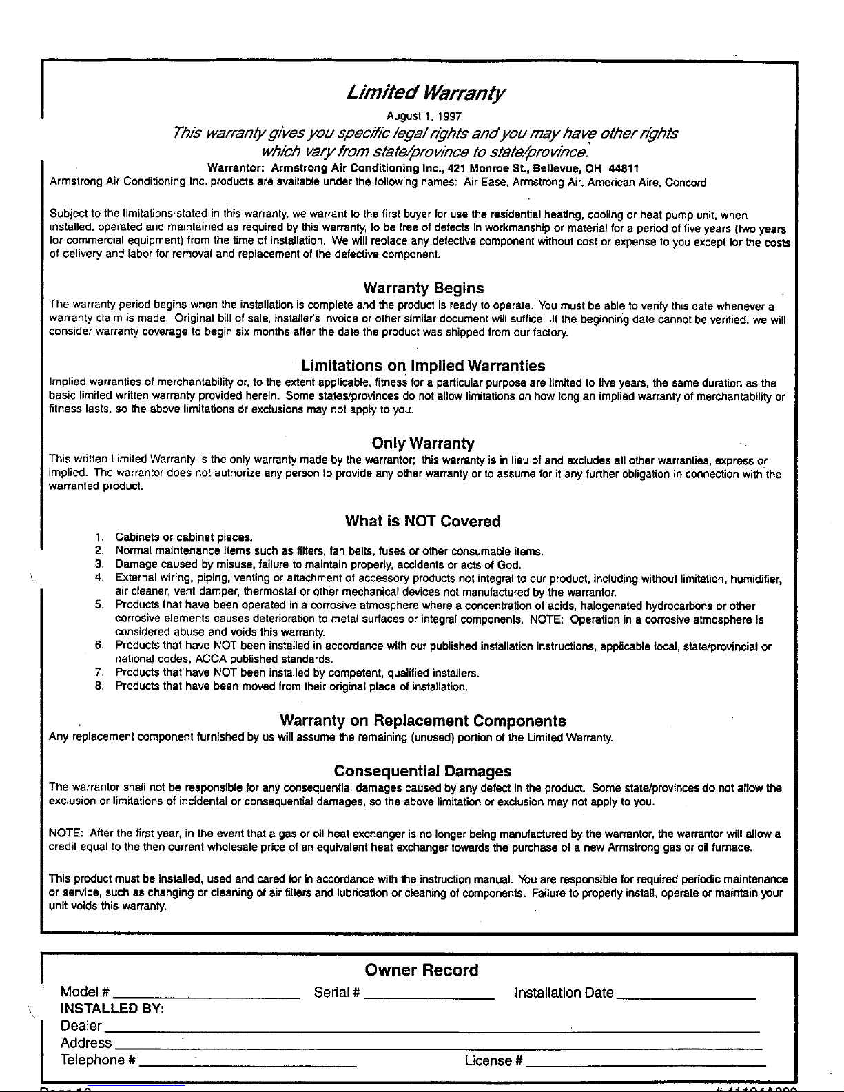
Limited Warranty
August 1, 1997
Thiswarran(ygivesyou specificlegalrightsand you may have otherrights
which vary from state/provincetostate/province.
Warrantor: Armstrong Air Conditioning Inc., 421 Monroe St., Bellevue, OH 44811
Armstrong Air Conditioning Inc products are available under the following names: Air Ease, Armstrong Air, American Airs, Concord
Subject to the limitafions.stated in this warranty, we warrant to the first buyer for use the residential heating, cooling or heat pump unit, when
installed, operated and maintained as required by this warranty, to be free of defects in workmanship or material for a pehod of five years (two years
for commercial equipment) from the time of installation. We will replace any defective component without cost or expense to you except for the costs
of delivery and labor for removal and replacement of the defective component.
Warranty Begins
The warranty period begins when the installafion iscomplete and the product is ready to operate. You must be able to verity this date whenever a
warranty claim is made. Original bill of sale, installer's invoice or other similar document will suffice..If the beginnir_gdate cannot be Verified. we will
consider warranty coverage to begin six months after the date the product was shipped from our factory.
Limitations on Implied Warranties
Implied warranties of merchantability or, to the extent applicable, fitness for a particular purpose are timited to five years, the same duration as the
basic limited written warranty provided herein. Some states/provincas do not allow limitations on how tong an implied warranty of merchantability or
fitness lasts, so the above limitations dr exclusions may not apply to you.
Only Warranty
This written Limited Warranty is the only warranty made by the warrantor; this warranty is in lieu of and excludes all other warranties, express or
implied. The warrantor does not authorize any person to provide any other warranty or to assume for it any further obligation in connection withthe
warranted product.
What is NOT Covered
I. Cabinets or cabinet pieces.
2. Normal maintenance items such as filters, fan belts, fuses or other consumable items.
3 Damage caused by misuse, failure to maintain properly, accidents or acts of God.
4 External wiring, piping, venting or attachment of accessory products not integral to our product, including without limitation, humidifier,
air cleaner, vent damper, thermostat or other mechanical devices not manufactured by the warrantor.
5 Products that have been operated in a corrosive atmosphere where e concentration of acids, halogenated hydrocarbons or other
corrosive elements causes deterioratfon to metsi surfaces or integral components. NOTE: Operation in a corrosive atmosphere is
considered abuse and voids this warranty
6 Products that have NOT been installed in accordance with our published installation instructions, applicable focal, state/provincial or
national codes, ACCA published standards.
7 Products that have NOT been installed by competent, qualified installers.
8 Products that have been moved from their odginai place of installation.
Warranty on Replacement Components
Any replscement component furnished by us will assume the remaining (unused) portion of the Limited Warranty.
Consequential Damages
The warrantor shall not be responsible for any consequential damages caused by any defect in the product. Some state/provinces do not allow the
exclusion or limitations of incidental or consequential damages, so the above limitation or exclusion may not apply to you.
NOTE: After the first year, in the event that a gas or oil heat exchanger is no longer being manufactured by the warrantor, the warrantor will allow a
credit equal to the then current wholesale price of an equivalent heat exchanger towards the purchase of a new Armstrong gas or oil furnace.
This product must be installed, used and cared for in accordance with the instructiott manual You are responsible for required pedodic maintenance
or service, such as changing or cleaning of air filters and lubrication or cleaning of components. Failure to properly install, operate or maintain your
unit voids this warranty.
!
Model #
, INSTALLED BY:
I ealer
Address
Telephone #
Owner Record
Serial # Installation Date
License #
Page 11
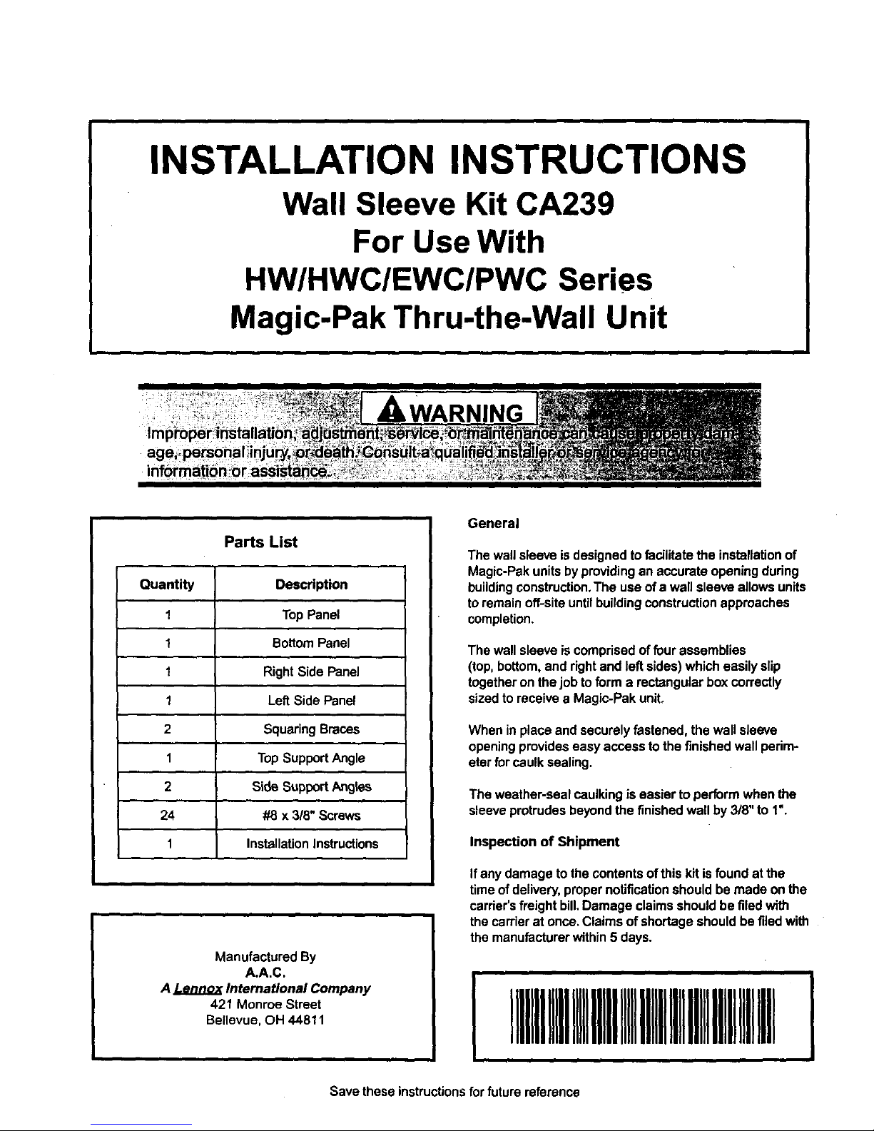
INSTALLATION INSTRUCTIONS
Wall Sleeve Kit CA239
For Use With
HW/HWC/EWC/PWC Series
Magic-Pak Thru-the-Wall Unit
age_
_WARNING
Parts List
Quantity Description
1 TopPanel
1 BottomPanel
1 Right Side Panel
1 LeftSide Panel
2 Squaring Braces
1 Top SupportAngle
2 SideSupportAngles
24 #8 x 3/8" Screws
1 InstallationInstructions
Manufactured By
A.A.C.
A Lennox International Company
421 Monroe Street
Bellevue,OH 44811
General
The wall sleeve isdesignedto facilitatethe installationof
Magic-Pakunits by providingan accurateopeningduring
buildingconstruction.The use ofa wall sleeve allows units
toremain off-siteuntilbuildingconstructionapproaches
completion.
The wall sleeve iscomprisedof fourassemblies
(top,bottom,and rightand left sides) which easily slip
togetheron the job toform a rectangularbox correctly
sizedto receive a Magic-Pak unit.
When inplace and securely fastened, the wall sleeve
openingprovideseasy access to the finishedwall pedm-
efarfor caulksealing.
The weather-seal caulkingiseasier to performwhen the
sleeveprotrudesbeyondthe finishedwall by 3/8" to 1".
Inspection of Shipment
Ifany damage tothe contentsofthis kit isfound at the
timeof delivery,propernotificationshould be made onthe
carrier's freight bill.Damage claimsshould be filedwith
thecarrierat once. Claimsof shortage should be filedwith
the manufacturerwithin 5 days.
1111111Ill1111111111IllIllIIIIIIIIIRillIIIIIIII
Save these instructionsforfuture reference
Page 12
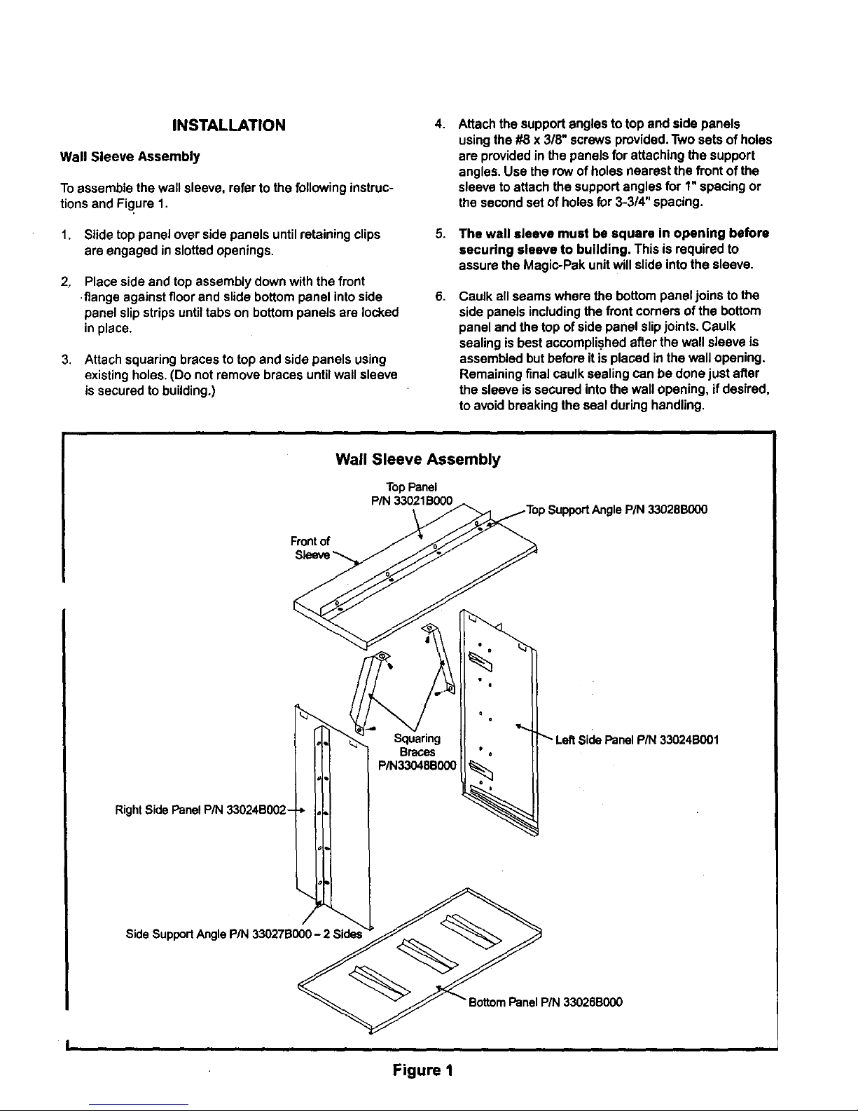
INSTALLATION
Wall Sleeve Assembly
Toassemble the wall sleeve, refer to the followinginstruc-
tionsand Figure 1.
1. Slidetop panel over side panels untilretaining clips
are engaged in slottedopenings.
2_
Place side and top assemblydown withthe front
flange againstfloorand slidebottom panel intoside
panelslip strips untiltabs on bottom panels are locked
inplace.
3. Attach squaring bracesto top and side panels using
existingholes. (Do not remove braces untilwall sleeve
issecured to building.)
4.
8.
Attachthe supportanglesto top and side panels
usingthe #8 x 318"screwsprovided.Two sets of holes
are providedin the panels for attaching the support
angles. Use the rowof holes nearest the front of the
sleeveto attach the support anglesfor 1"spacing or
the secondset of holesfor 3-3/4" spacing.
The wall sleeve must be square in opening before
securing sleeve to building. This is requiredto
assure the Magic-Pak unitwill slide intothe sleeve.
Caulk all seams where the bottompaneljoins tothe
side panels includingthefront corners ofthe bottom
panel and the top of side panel slipjoints.Caulk
sealing is bestaccomplishedafterthe wall sleeve is
assembledbutbefore Risplaced inthe wall opening.
Remainingfinalcaulk sealing can be done just after
the sleeve issecured intothe wall opening, if desired,
to avoidbreakingthe seal duringhandling.
Wall Sleeve Assembly
TopPanel
P/N33021B000
Frontof
RightSide Panel P/N 33024B002-
Squaring
Braces
P/N33048B000
LeftSide Panel P/N 33024B001
Side SupportAnglePIN 33027BG00- 2 Side=
Figure I
Page 13
Furthersealing againstair infiltrationmustbe done alter
the Magic-Pak unitis installedin the wall sleeve and utility
connectionshavebeen completed (see Sealing/Weath-
erproofing Wall Sleeves section).
Wall Sleeve Installation
The wall sleeve may be installedfrom either the insideor
outsideofthe building.
Some builderswillattach the wall sleeve to the support
wallthroughthe side supportangleswhether they are
insertingthesleeve fromthe outsideor the inside.Othem
willuse the side angles simplyas a locating"stop"to
achievethe appropriatedimensionwhileshootingfasten-
ersthroughthe sides ofthe wallsleeve into the supporting
wall.In either case,the wall sleeve must be fastened to
the supporting wall and notto thefinishedwall.
The sleeve may extend farther than 1"beyondthe finished
wall,but reachingtheperimeter ofthe openingfrom inside
for sealing becomes increasinglydifficult.In any case,
adequate safety precautionsmust beconsideredto
protectpersonnel.
Instailing Wall Sleeve from Inside
The most popular method ofinstallingthe wallsleeve is
from the inside of the buildingwiththe weather seal
appliedfrom the outsideas the finishwall is applied.
Instalflng Wall Sleeve from Outside
In manyhigh-rise constructionapplications,contractors
insertthe wall sleevesfrom the outsidewhilethewall is
beingconstructed.The two-sidedsupport anglesshould
then be attached to the wall sleeve sides at a locationthat
willexceed the thicknessofthe outsidefinish wallbythe
recommended3/8" to 1"dimension.
Forexample, ifthe supportingwall is concreteblockwith a
brickfacing, there is usuallya space betweenthe block
and the brick.This space dimensionmust be addedto the
widthof the brick (plus3/8" to 1") so thatwhen the sleeve
is inserted intothe blockwall opening, up to the angles
and fastened to the blockwallbefore thebrickis installed,
the sleevewilt protrudebeyondthe finishedbrickby 3/8"
to 1",as needed for caulk sealing.
The same applies if the supportingwall iswoodframe.
One may insertthe sleevefromthe outside upto the
angleslocated on each side,allowingforthe thicknessof
sheathing,finishsiding,and caulk sealing.
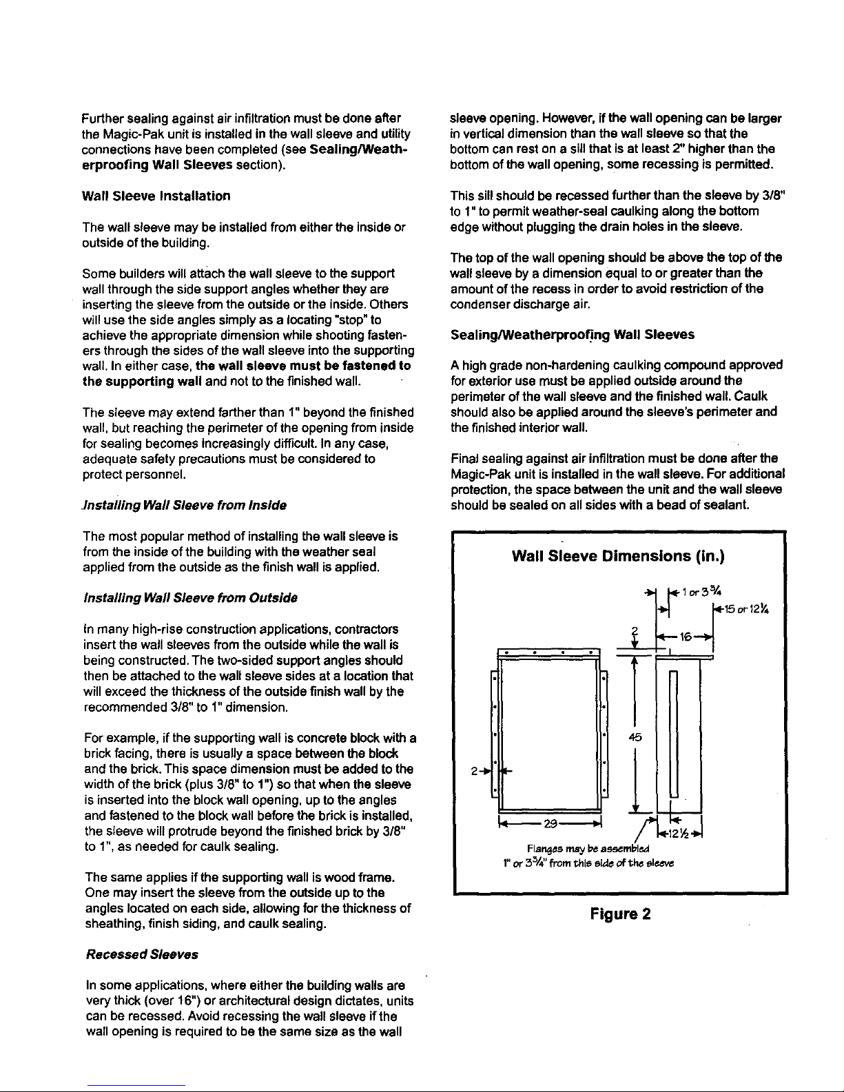
Recessed Sleeves
In someapplications,where either the buildingwallsare
verythick(over 16") or architecturaldesign dictates,units
can berecessed. Avoidrecessingthewall sleeve ifthe
wallopening is requiredto be the same size as the wall
sleeveopening. However,if the wall openingcan be larger
inverticaldimensionthan the wall sleeve sothat the
bottomcan rest ona sillthat isat least2"higher thanthe
bottomof thewall opening,some recessing ispermitted.
Thissillshouldbe recessed further than the sleeve by3/8"
to 1"to permitweather-seal caulking along the bottom
edge withoutpluggingthe drain holes in the sleeve.
The topof the wall opening should be above the topof the
wall sleevebya dimensionequal to or greater than the
amountof the recess in orderto avoid restrictionof the
condenserdischargeair.
Sealing/Weatherproofing Wall Sleeves
A highgrade non-hardeningcaulkingcompoundapproved
forexterioruse mustbe appliedoutsidearoundthe
perimeterofthe wall sleeveand the finishedwall. Caulk
shouldalso beapplied around the sleeve's perimeter and
thefinishedinteriorwall.
Final sealingagainst air infiltrationmust be donealter the
Magic-Pakunit is installedin thewall sleeve. For additional
protection,the space between the unit and the wall sleeve
shouldbe sealed on all sideswith a bead of sealant.
2--I=
Wall Sleeve Dimensions (in.)
-$--
I
i
45
I
I
_t._
I.---- z9- -,4
Flar_es may b_ assembl_l
1"or 5_/4"from this e_e ofthe elc_v_
<.. 1or 3_/4
.16,.._15 or 12_
!
Figure 2
Page 14

I_A_T_°.I 4"948°96----I
I
INSTALLATION
ANDMAINTENANCE
INSTRUCTIONS
PWCSERIES
SELF-CONTAINEDHEATPUMP
ManufacturedBy
ARMSTRONG AIR CONDITIONING INC.
A LENNOXInternationalInc. Company
421 MonroeStreel
Page 15
I PART.OI .,,,,RO..I OATE12''0 I SUPERSEOESI I PAGE2OF,0
GENERAL
Theseinstructionsexplainthe recommendedmethodof installationof the PWCheatpumpunit and associatedelec-
tricalwiring.
This unit is designed and approvedfor use as a self-containedairto air heat pump system.
These instructions,and anyinstructions packagedwith maling componentsand/or accessories,shouldbe carefully
read priorto beginning installation.Note parliculady anyCAUTIONSor NOTESin theseinstructions andall labels on
the unit.
Theseinstructionsare intendedasa generalguideonly.for use byqualifiedpersonnel,anddo notsupersedeanyna-
tionalor localcodesinanyway. Compliancewithalllocal,state, provincial,or nationalcodespertainingtothistypeof
equipmentshouldhe determinedprior to installation.
INSPECTIONOFSHIPMENT
Uponreceiptof equipment,carefullyinspectit forpossibleshippingdamage.Ifdamageis found,it shouldbe noted
on the carder's freightbill. Take specialcareto examinethe unit insidethecartonif the cartonis damaged.File a
claimwith the transportationcompany.
If any damagesare discoveredand reportedto the carrier DONOTINSTALLTHE UNIT as claim may be denied.
Checkthe unitrating plate to confirmspecificationsare as ordered.
CAUTION:INSTALLATIONANDSERVICINGOFAIR CONDITIONINGEQUIPMENTCANREHAZARDOUSDUETO IN-
TERNALREFRIGERANTPRESSUREAND LIVE ELECTRICALCOMPONENTS.ONLYTRAINEDANOQUALIFIEDSER-
VICE PERSONNELSHOULDINSTALL,REPAIR,OR SERVICETHIS EQUIPMENT.
WARNING
FORYOURSAFETY
DONOTSTOREOR USEGASOLINEOROTHERFLAMMABLEVAPORSAND LIQUIDSINTHE VICINITYOFTHIS
ORANY OTHERAPPLIANCE.
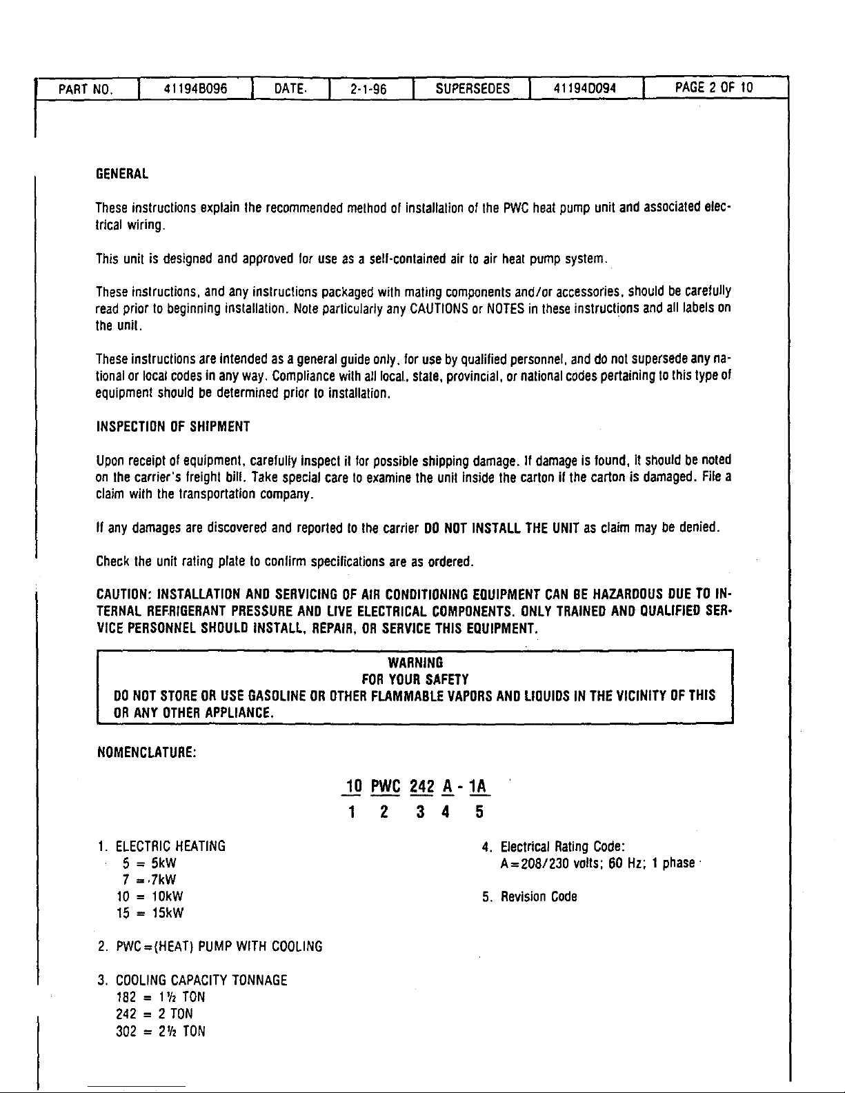
NOMENCLATURE:
1. ELECTRICHEATING
5 = 5kW
7 = .7kW
10 = 10kW
15 = 15kW
2. PWC=(HEAT) PUMPWITH COOLING
3. COOLINGCAPACITYTONNAGE
182 = 1½ TON
242 = 2 TON
302 = 2½ TON
10 PWC 242 A-1A
1 2 3 4 5
4. ElectricalRatingCode:
A=208/230 volts; OOHz; 1 phase,
5. RevisionCode
Page 16

PARTNO. I 41194BOg6I DATE I 2-1-96 I SUPERSEDESI 411940094 I PAGE3OFIO
I
LOCATION
Thedesigniscertifiedfor through-the-wallinstallationonly. Theinteriorportionsoftheunit may be surroundedbya
closetwith clearancestocombustiblematerial heldto 0" at sides, 0" top and O" frontof the plenum.
Thegrillesideofthe unitmay beflushwith orextendbeyondthefaceof theexteriorwall, butshouldnotberecessed
morethan two(2) inchesfrom the face of thebuildingand shouldnotbe obstructedwithtrees, landscapematerials,
or buildingstructure.
Thereis nominimumclearancerequiredonlocatinga unittoaninteriorcornerofa building. If theunitis tobeenclos-
ed, provisionsshouldbemadeallowingaccesstothe indoorsideof theunitfor changingfilters.and forinspection.At
least33" of unobstructedspaceshouldbe providedin front of the indoorside. whetherenclosedornoL to permit
removalof the coolingchassisshouldrepairsor inspectionbe required.
If this unitis installedina residentialgarageit must be locatedor protectedtoavoidph_,sicaldamagebyvehicles.
Thisunit must be installedso that no electricalcomponentsare exposedto water.
INSTALLATION
CAUTION:THESLEEVEISNOTINTENDEDASTHESOLESUPPORTFORTHEUNIT. ANADDITIONALSUPPORTMUST
BE PROVIDEDNEARTHE RETURNOPENINGON THE UNIT FOR ADEQUATESUPPORT.THE USEOF VIBRATION
ISOLATIONMATERIALBETWEENTHE UNIT ANDTHE SUPPORTIS RECOMMENDED,
CAUTION:THIS UNITMUST BEINSTALLEDLEVELFORPROPERDRAINAGEOFTHE CHASSISBASEPANAND UNIT
DRAINPAN.
WITHOUTWALLSLEEVE
Measurethesizeoftheunit andprovideanopeninginan outsidewall that willaccepttheunit. Localordinancesmay
require a steel lintel to supportthe wall abovethe opening.Thisopeningmust be square in all corners.
Positiontheunitsothat thegrilleson the outsidefaceof the unit areflushor extendbeyondthe faceof the exterior
wall,but notrecessedmorethantwo(2) inchesfromthe faceof thebuilding.PROVIOEA SUPPORTUNDERTHE UNIT
INSIDETHE BUILDING.Makesure thattheinsidesupportdoesnot blockthereturnair. The unitshouldbeinstalled
level.
Sealthe spacebetweentheunit and the buildingopeningusinga non-hardeningcaulkingcompound.Thesealmust
beweather-tighttoprevententranceof moistureandwater intothe building.Makesure thedrainholesin the base
are notpluggedwith caulking.
WITH WALL SLEEVE
Seethe installationinstructionspacked with Ihe wall sleeveto assembleand mountin a wall. Make sure that the
gasketsattachedtothe sleeveare notdamaged.Assurethatthe unit iscompletelyseatedagainstthe gasketsonthe
wall sleeve.
Sealspacebetweenwall sleeveand buildingopeningusingnon-hardeningcaulkingcompound.This seal mustbe
watertight.
CONDENSATEDRAIN
Install theplasticdraintube(furnished)overthe5/8" O.O. fittingwelded to thecondensatepan. Connectotherend
ofthe draintubeto trappeddrain line(See Figure2). Theplasticdrain connectiontothechassisbaseisprovidedso
thatit may bedisconnectedfromthepermanentdrain tubingin thebaseof unitin theeventit becomesnecessaryto
removethe chassisassembly.
L
The drain line should pitch gradualtydownwardat least 1" per 10 footof horizontalrun to the opendrain.
Be certainthat the plasticdrain tubing hastreedrainageand is notcrimpedor flattenedat anybend.
Page 17

PA.T.O.I ,,,,_,,.0_,I 0','_ I _'"_ I SU"ERSEOESI ""_"00_"I PA_E,'O_,O
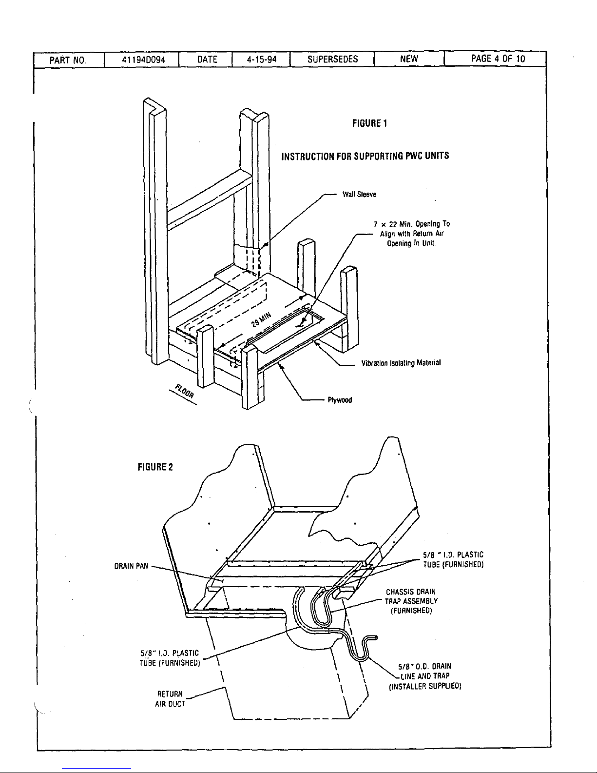
FIGURE1
INSTRUCTIONFORSUPPORTINGPWCUNITS
Wall Sleeve
7 x 22 Min. OpeningTo
A#ignwith'Return Air
Openingin Unit.
VibrationIsolatingMaterial
%
Plywood
FIGURE2
DRAINPAN
5/8 " I.D. PLASTIC
(FURNISHED)
CHASSISDRAIN
'ASSEMBLY
(FURNISHED)
5/8" I,O. PLASTIC
TU"BE(FURNISHEO]
\
RETURN
AIR DUCT\
5/8" O.O. DRAIN
_LINEAND TRAP
(iNSTALLERSUPPLIED)
Page 18

.ARTNO.I "f9"Bog I OATEI 2"t'g6I .SUPERSEOESI 4119'0094[ PAGESOFtO
LIMITATIONS
The unit shouldbe installedin accordancewithall nationaland local safetycodes.
Limitationsof the unitand appropriateaccessoriesmust also be observed.
The unitmustNOTbe installedwithany ductwork in theoutdoorairstream,Theoutdoor fanisnotdesignedtooperate
againstany additionalstaticpressure.
Minimum and maximum operating conditionsmust be observedto assure maximumsystem performancewith
minimum servicerequired,
TABLE1 - APPLICATIONLIMITATIONS
OUTDOORAMBIENTAIR TEMP. OF INDOORAMBIENTTEMP. °F
MIN, DB - COOL MAX, DB MIN. MAX.
65 COOL HEAT OB/WB DB DB/WB DO
125 75
COOL HEAT COOL HEAT
62/57 50 90/72 80
DUCTWORK
Ductwork shouldbe designedand sizedaccordingto applicablemethods fromthe Air ConditioningContractorsof
America(ACCA).
It is recommendedthat supplyand return duct connectionsat the unit be madewith flexible joints.
' The supplyand return air ductsystemsshouldbe designedfortheCFM staiicrequirementsofthejob. Theyshould
NOT be sized Io matchthe dimensionsol theduct connectionsonthe unit.
NOTE:SUPPLYDUCTFLANGESARESHIPPEDFLATAND MUSTBEBENTUP BEFOREAFI'ACHINGTHESUPPLYDUCT,
ToconnectthereturnducttotheunJt,usea straightpieceofduct22" wideby 7" deep.Inserttheductintothereturn
openingin thebottomoftheunit. Flangetheductovertheexistingflangesaroundtheopeninginsideunit.Makesure
thatall sidesoftheductare flangedovertopermitremovalofcoolingchassisifrequired.Usea flexibleconnectionto
attachremainderofreturnduct.The returnductshouldbesealedto theunitcasingand terminateoutsidethe space
containingthe furnace,
NOTE:THE RETURNDUCTMUST ALLOWFORTHE UNIT DRAINPANCONNECTIONSAND DRAINTUBE.
CAUTION:00 NOT SCREWINTOTHE SIDEOF THE DRAIN PAN.
AIR FILTER
Allindoorreturn airmustbefiltered.A permanent-type filter isfurnished withtheunit. locateddirectly behindtheac-
cess panel. Removingthe panelpermitsaccessto the filter.
The tiltershouldbecleanedatleastthreetimesduringeachof the heatingandcoolingseasons,ormorefrequently if
unusualconditionsare encountered.To cleanthe permanentfiller, shakefilter to removeexcessdirt and/or use
vacuumcleaner. Washtilter in soapor detergentwaterand replacealter filteris dry.
The filter suppliedneed not be oiledalter washing.
Page 19
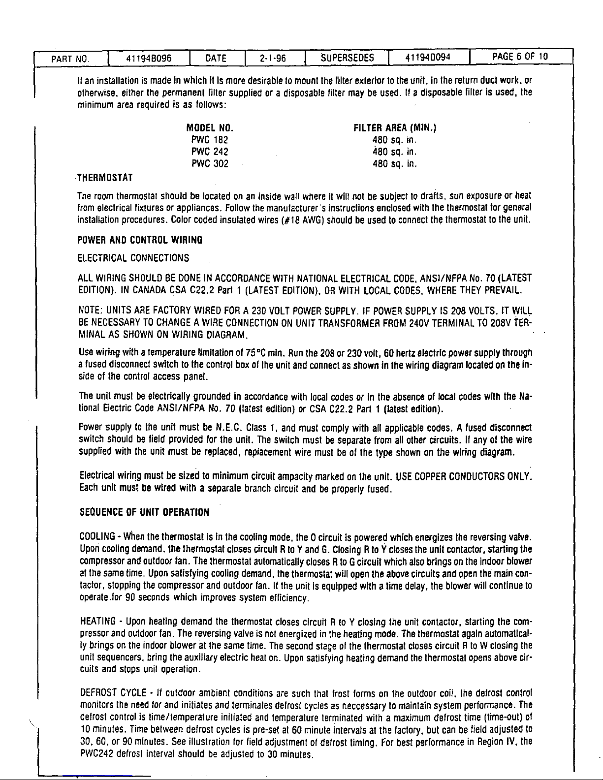
I PA.TNoI .tt9..o96I DATE12196 I SUPERSEDESI ,rig.DO9.I PAGE,O.tO
It an installation is madein which it is moredesirableto mountthe filter exterior tothe unit, in the return duct work, or
olherwise, either the permanent filter supplied or a disposablefilter may be used. If a disposable filter is used, the
minimum area required is as follows:
MOOELNO. FILTERAREA(MtN.)
PWC 182 480 sq. in.
PWC242 480 sq. in.
PWC302 480 sq. in.
THERMOSTAT
The room thermostatshouldbe locatedonan insidewall whereitwilt not be subjectto drafts, sun exposureor heat
from electricalfixturesorappliances.Followthemanufacturer'sinstructionsenclosedwiththethermostatforgeneral
installationprocedures.Colorcodedinsulatedwires(#18 AWG)shouldbe usedtoconnectthethermostattothe unit.
POWERAND CONTROLWIRING
ELECTRICALCONNECTIONS
ALLWIRINGSHOULDBEDONEIN ACCORDANCEWITHNATIONALELECTRICALCODE,ANSI/NFPA NO.70 (LATEST
EDITION).IN CANADA(_SAC22.2 Part 1 (LATESTEDITION),ORWITH LOCAL CODES,WHERETHEY PREVAIL.
NOTE:UNITSAREFACTORYWIREDFORA 230 VOLTPOWERSUPPLY. IF POWERSUPPLYIS 208 VOLTS.IT WILL
BENECESSARYTOCHANGEAWIRE CONNECTIONONUNIT TRANSFORMERFROM240VTERMINALTO20SV TER-
MINALAS SHOWNONWIRING DIAGRAM.
Usewiringwitha temperaturelimitationof 75°C rain. Runthe208 or 230 volt,60 hertzelectricpowersupplythrough
a fuseddisconnectswitchtothe controlboxof the unitandconnectas showninthe wiringdiagramlocatedon the in-
sideof the controlaccesspanel.
The unitmustbe electricallygroundedin accordancewith local codesor in the absenceof localcodeswith the Na-
tionalElectricCodeANSI/NFPA No. 70 (latestedition)or CSAC22.2 Part 1 (latestedition).
Powersupplyto the unit must be N.E.C. Class1, and must complywithall applicablecodes.A fused disconnect
switchshouldbe field providedfor the unit. The switchmust be separatefromall othercircuits. If anyofthe wire
suppliedwith the unit must be replaced, replacementwiremustbe of the type shownon the wiring diagram.
Electricalwiringmust besized tominimumcircuitampacitymarkedonthe unit. USECOPPERCONDUCTORSONLYI
Eachunit must bewired with a separatebranchcircuitand be properlyfused.
SEQUENCEOFUNIT OPERATION
COOLING- WhenthethermostatisIn the coo[ingmode,the Ocircuitis poweredwhichenergizesthereversing valve.
Uponcoolingdemand,thethermostatclosescircuitRtoYand G.ClosingR toY closestheunitcontactor,startingthe
compressorandoutdoorfan. ThethermostatautomaticallyclosesRto Gcircuitwhichalsobringsonthe indoorblower
at thesametime. Uponsatisfyingcoolingdemand,thethermostatwillopentheabovecircuitsandopenthemaincon-
tactor,stoppingthe compressorand outdoorfan.If the unitis equippedwith a time delay,the blowerwillcontinueto
operate.for 90 secondswhich improvessystemefficiency.
HEATING- Uponheatingdemandthe thermostatclosescircuit R to Y closingthe unitcontactor,startingthe com-
pressorandoutdoorfan.The reversing valveis notenergizedin the heating mode.Thethermostatagainautomatical-
ly bringsonthe indoorblower at the sametime. Thesecondstageofthethermostatclosescircuit RtoW closingthe
unitsequencers,bringthe auxiliaryelectricheaton.Uponsatisfyingheatingdemandthethermostatopensabovecir-
cuits and stopsunit operation.
DEFROSTCYCLE- If outdoor ambientconditionsare such that frost formson theoutdoorcoil, the defrost control
monitorsthe need for andinitiates and terminatesdefrost cyclesasneccessary to maintain system performance.The
defrost controlis time/temperatureinitiated and temperature terminated with a maximum defrost time (time-out)of
10 minutes. Timebetweendefrost cyclesis pre-set at 60 minuteintervalsat thefactory, but canbefield adjustedto
30, 60, or 90 minutes.Seeillustrationfor field adjustmentofdefrosttiming.For bestperformancein RegionIV, the
PWC242defrostinterval shouldbeadjustedto30 minutes.
Page 20

PA...o,I .,,9.o09.I
IDNSTALLATION
AN MAINTENANCE
INSTRUCTIONS
PWCSERIES
SELF-CONTAINEDHEATPUMP
PARTNO.] 4,,94°O94I OA_E] 4-,5-94I SU_RSEOESI .EWI _'AGE_O_IOI
Manulaclured By
ARMSTRONG AIR CONDITIONING INC,
A LENNOXInternationalInc. Company
421 Monroe Slreel
Bellevue, OH44811
Page 21

!
PART NO.
I 4,tg4ooB4I DATEI 4lsg, I SUPERSEOESI NEWI PAGE2OFlO
GENERAL
Theseinstructionsexplainthe recommendedmethodof installationof the PWCheal pumpunitandassociatedelec-
trical wiring.
This unil is designed and approvedfor use as a self-contained air Io air heat pump system.
Theseinstructions, andany instructions packaged wilh mating componen[sandlor accessories,should becarefully
read prior to beginning inslallation, Noleparlicularly any CAUTIONSor NOTESin these instructions and all labelson
the unit.
Theseinslructions are intended asa generalguideonly, foruse byqualifiedpersonnel, andtienotsupersedeanyna-
tionalorlocalcodesinanyway. Compliancewithall local, state,provincial,ornationalcodespertainingtothistypeof
equipmentshouldbe determinedpriorto instaltalion.
INSPECTIONOFSHIPMENT
Uponreceiptof equipment,carefullyinspectil for possibleshippingdamage. If damageis found, itshouldbenoied
on the carrier'sfreight bill. Take specialcare to examinethe unitinsidethe cartonif thecartonisdamaged. Filea
claimwilh thetransportationcompany,
If anydamages arediscovered and reportedtothe carrierDONOTINSTALLTIlE UNIT as claimmay be denied.
Checkthe unitrating plateto confirmspecifications are asordered.
CAUTION:INSTALLATIONAND SERVICINGOFAIR CONDITIONINGEQUIPMENTCAN BEHAZARDOUSDUETOIN-
TERNALREFRIGERANTPRESSUREAND LIVE ELECTRICALCOMPONENTS.ONLYTRAINEDANDQUALIFIEDSER-
VICE PERSONNELSHOULDINSTALL,REPAIR,ORSERVICETHIS EQUIPMENT.
I WARNING
FORYOURSAFETY
DONOTSTOREORUSEGASOLINEOROTHERFLAMMABLEVAPORSANDLIQUIDSIN THEVICINITYOFTHIS
ORANY OTHERAPPLIANCE.
NOMENCLATURE:
10 PWC 242 A-1A
1 2 3 4 5
1. ELECTRICHEATING 4. ElectricalRatingCode:
5 = 5kW A=208/230 volts;60 Hz; 1 phase
7 = 7kW
10 = lOkW 5. RevisionCode
15 = 15kW
2. PWC=(HEAT) PUMPWITH COOLING
3. COOLING CAPACITYTONNAGE
182 = 1'IzTON
242 = 2 TON
302 = 2'/2TON
Page 22

I PA,,NO.I ,, g,o094I DATEI '-fS-g'I SUPERSEDESI ,EW I PAGE3OF,O
LOCATION
Thedesign iscertifiedfor through-the-wallinstallationonly.The interiorportionsof theunit may besurroundedby a
cJosetwith clearancesto combustiblematerial held to O" at sides, 0" topand 0" frontof the plenum.
Thegrille sideof the unit maybe flush with or extendbeyondthefaceof theexteriorwall,but shouldnotberecessed
more than two (2) inchesfrom the face of thebuilding andshould notbeobstructed with trees, landscapematerials,
or building structure.
Thereis no minimum clearancerequired on locatinga unit toan interior cornerof a building. If the unit is tobe enclos-
ed, provisionsshouldbe madeallowing accessto the indoorside of the unit tot changing filters andfor inspection. At
least 33" ol unobstructed space should be provided in fronl of the indoorside, whether enclosed or not, to permit
removalof the coolingchassis shouJdrepairs or inspection be required,
If this unit is installed in a residential garage it must belocated or protectedto avoidphysical damageby vehicles.
This unit must be installed so that no electrical componentsare exposedtowater.
INSTALLATION
CAUTION:THESLEEVEIS NOTINTENDEDASTHESOLESUPPORTFORTHEUNIT.ANADDITIONALSUPPORTMUST
BEPROVIDEDNEARTHE RETURNOPENINGONTHE UNIT FORADEQUATESUPPORT.THE USE OF VIBRATION
ISOLATIONMATERIALBETWEENTHE UNIT AND THESUPPORTIS RECOMMENDED.
CAUTION:THISUNITMUSTBE INSTALLEOLEVELFORPROPERDRAINAGEOFTHECHASSISBASEPANAND UNIT
DRAINPAN.
WITHOUTWALLSLEEVE
Measurethesizeofthe unit andprovideanopeningin an outsidewallthatwillaccepttheunit. Localordinancesmay
require a steel lintelto supportthe wall abovethe opening.This openingmust be square in all corners.
Positionthe unitsothatthe gritles on the outsideface of theunitare flush or extendbeyondthe faceof theexterior
wall, but notrecessedmorethan two (2) inchesfromthe face of thebuilding. PROVIDEASUPPORTUNDERTHEUNIT
INSIDETHE BUILDING.Makesure that theinsidesupport does not block the return air. The unitshouldbe installed
level.
Sealthespacebetweenthe unitandthe buildingopening usinga non-hardeningcaulkingcompound.Thesealmust
be weather-tight toprevententrance ol moisture andwaterinto thebuilding. Make surethe drainholesin the base
are not plugged with caulking.
WITH WALL SLEEVE
Seethe installationinstructionspacked with the wall sleeveto assembleandamountin a wall. Make surethat the
gaskets attachedtothe sleeveare not damaged. Assurethat the unitiscompletelyseatedagainst the gaskets onthe
wall sleeve.
Sealspacebetweenwail sleeveand building opening using non-hardeningcaulkingcompound.This sealmust be
watertight,
CONDENSATEDRAIN
Install theplastic drain tube(furnished) over the 5/8" O.D. fitting weldedtothe condensatepan. Connectotherend
of the drain tubetotrapped drain line (See Figure2). Theplastic drain connectionto thechassisbaseis providedso
that it may be disconnected from the permanent drain tubingin thebaseof unitin theevent it becomesnecessaryto
remove the chassis assembly.
The drain lineshouldpitch gradually downward at least 1" per 10 loot of horizontal run to the open drain.
Be certainthat the plaslic drain tubing has freedrainage and is not crimpedor flattened at any bend,
Page 23
I PART.O.I "(940094[ DArEI 4-_5-9'I SUPERSEDES
NEW [
PAGE4 OF 10
FIGURE1
INSTRUCTIONFORSUPPORTINGPWCUNITS
WallSleeve
7 x 22 Mio. OpeningTo
Align with ReturnAir
Opening _n Unit.
]
L_
VibrationisolatingMaterial
%
FIGURE2
5/8 "I.D. PLASTIC
(FURNISHED)
CHASSISDRAIN
(FURNISHED)
5/8" I.D. PLASTIC
TUBE(FURNISHED)
RETURN
NR DUCT
\
\ \
\
518" O.O. DRAIN
"-UNE AND TRAP
(INSTALLERSUPPLIED)
Page 24

PA,TNOI 4tt94OOB4I DA EI 41594]SUPERSEDESI NEWI PAGE OFtO
LIMITATIONS
The unitshouldbe installedin accordancewith all national and localsafetycodes.
Limitationsofthe unit and appropriateaccessoriesmust alsobe observed.
TheunitmustNOTbeinstalledwithany ductworkin theoutdoorairstream.Theoutdoorfan is notdesignedto operate
againstany additionalstatic pressure.
Minimumand maximum,operatingconditionsmust be observed to assure maximumsystem performancewith
minimum servicerequired.
TABLE1 - APPLICATIONLIMITATIONS
.
OUTDOORAMBIENTAIR TEMP. OF
MIN. OB" COOL MAX. OB
65 COOL HEAT
125 75
DUCTWORK
INDOORAMBIENTTEMP. OF
MIN. MAX.
DB/WB DB DB/WB DB
COOL HEAT COOL HEAT
62/57 50 90/72 80
Ductworkshouldbe designed_lndsized accordingto applicablemethodsfrom theAir Conditioning Contractorsof
America(ACCA).
It is recommendedthatsupplyand return duct connectionsat theunit be madewith flexible joints.
The supptyandreturn air ductsystemsshouldbedesignedfor the CFMstaticrequirementsof the job. Theyshould
NOTbe sizedtomatch thedimensionsof the ductconnectionsonthe unit,
NOTE:SUPPLYDUCTFLANGESARESHIPPEDFLATANDMUSTBEBENTUPBEFOREATTACHINGTHESUPPLYDUCT.
Toconnectthe returnducttotheunit.usea straightpieceof duct 22" wideby 7" deep.Inserttheductintothereturn
openinginthebottomoftheunit. Flangetheductovertheexistingflanges aroundtheopeninginsideunit. Make sure
thatallsidesofthe ductare flangedovertopermitremovalofcoolingchassisif required.Usea flexible connectionto
attachremainderofreturnduct.Thereturnductshouldbesealedtothe unit casingandterminateoutsidethespace
containingthefurnace.
NOTE:THE RETURNDUCTMUST ALLOWFORTHE UNIT DRAINPANCONNECTIONSANDDRAINTUBE.
CAUTION:DONOTSCREWINTOTHE SIDEOFTHEDRAINPAN.
AIR FILTER
Allindoor return airmust befiltered.A permanent-typefilter isfurnished withtheunit,locateddirectly behindtheac-
cess panel. Removingthe panel permits access to the filter.
Thefiltershouldbe cleanedat leastthreetimesduring eachof theheatingandcoolingseasons,or morefrequently if
unusual conditionsare encountered. To clean the permanent filter, shake filter to removeexcessdirt and/or use
vacuum cleaner. Wash filter in soap or detergent water and replaceafter filter is dry.
The filtersupplied neednot be oiled afterwashing.
Page 25

PARTNO. ] 41194D094 ] DATE ] 4-15-94 ] SUPERSEDES ] NEW ] PAGE6 OF 10
If aninstallation is madein which it is more desirabletomount thefilter exterior tothe unit, inthe return duct work, or
otherwise, either the permanent filter suppliedor a disposable filter may be used. If a disposable filter is used, the
minimum area required is as follows:
MODELNO, FILTERAREA(MIN.)
PWC182 480 sq. in,
PWC242 480 sq. in.
PWC302 480 sq. in.
THERMOSTAT
The roomthermostatshouldbe locatedonan insidewallwhereit willnot besubject todrafts, sun exposureor heat
fromelectrical fixtures or appliances. Followthemanufacturer's instructions enclosedwith thethermostat for general
installationprocedures. Color codedinsulated wires (# !8 AWG)should be usedto connectthethermostat to the unit.
POWERANDCONTROLWIRING
ELECTRICALCONNECTIONS
ALL WIRINGSHOULDBEDONEIN ACCORDANCEWITHNATIONALELECTRICALCODE,ANSI/NFPANo. 70 (LATEST
EDITION).IN CANADACSAC22.2 Part 1 (LATESTEDITION),ORWITH LOCALCODES,WHERETHEYPREVAIL:
Usewiringwithatemperaturelimitationof75°C rain. Runthe 208or 230 volt,60hertzelectric powersupplythrough
a fused disconnectswitch to thecontrolboxof the unit andconnectas showninthe wiringdiagramlocatedon the in-
side ofthe control access panel.
The unitmust beelectricallygrounded in accordancewithlocal codesor in theabsenceof localcodeswiththe Na-
tional Electric CodeANSI/NFPA No. 70 (latest edition)or CSAC22.2 Part 1 (latest edition).
Powersupplyto the unit must be N.E.C. Class1, and mustcomplywith all applicable codes.A fused disconnect
switch should be field providedfor the unit. Theswitchmust be separatefrom all othercircuits. If any of the wire
supplied with the unit must be replaced, replacementwire must be of the type shown onthe wiringdiagram.
Electricalwiringmust be sized tominimumcircuitampacitymarked on theunit. USECOPPERCONDUCTORSONLY.
Eachunit must bewiredwith a separatebranchcircuitand be properlyfused.
SEQUENCEOFUNIT OPERATION
COOLING- Whenthe thermostatis inthe coolingmode,the 0 circuitis poweredwhichenergizesthereversing valve.
Uponcoolingdemand,the thermostat closescircuitRto YandG. ClosingRtoY closesthe unit contactor,startingthe
compressorandoutdoorfan. Thethermostatautomatically closesRtoGcircuitwhichalsobrings ontheindoor blower
atthe sametime. Uponsatisfying coolingdemand,the thermostatwill opentheabovecircuitsand openthe main con-
tactor, stoppingthe compressorandoutdoorfan. If theunit is equippedwith a time delay, the blower will coritinueto
operatefor 90 seconds whichimprovessystemefficiency.
HEATING- Uponheating demand the thermostatclosescircuitRto Y closingthe unit contactor,starting the com-
pressor andoutdoorfan. Thereversingvalveis.no.t-energizedin the heating mode.Thethermostatagainautomatical-
ly brings on the indoorblowerat the sametime. Thesecondstage of thethermostatclosescircuftRto W closingthe
unit sequencers, bring theauxiliary electric heaton. Uponsatisfying heating demandthe thermostatopensabovecir-
cuitsand stops unit operation.
i
DEFROSTCYCLE- if outdoor ambient conditions are such that frost forms on the outdoorcoil,the defrost control
monitorsthe need for andinitiatesandterminates defrost cycles as neccessary tomaintain systemperformance. The
defrost controlis time/temperature initiated and temperatureterminatedwith a maximum defrost time (time-out) of
10 minutes. Timebetweendefrost cycles is pre-set at 60 minute intervals at the factory, but can be field adjusted to
30, 80, or 90 minutes. Seeillustralion for field adjustment of defrost timing. For best performancein RegionIV, the
PWC242defrost interval should be adjusted to 30 minutes.
Page 26
PA,T,O.I ,tt,,O0,,( [ l SUPERSEOESI NEW l PAGE OFtO
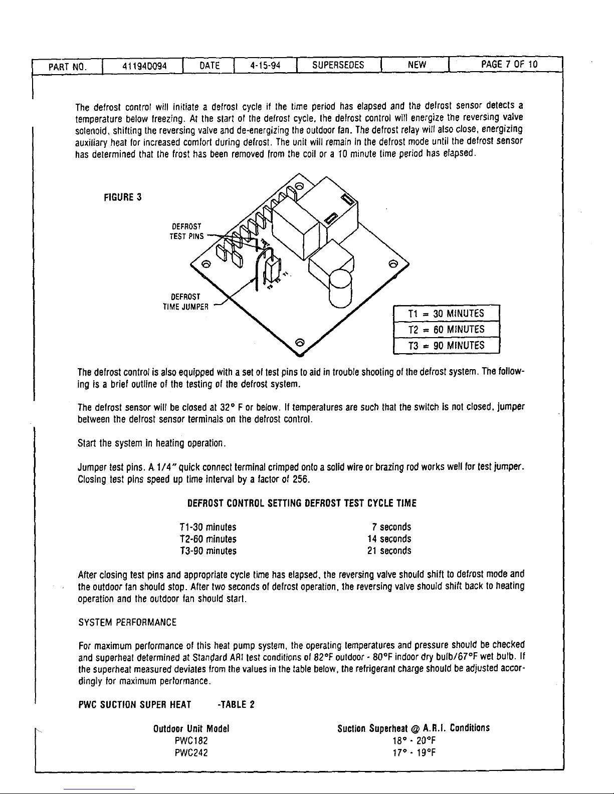
The defrost controlwill initiatea defrosl cycle if the time period haselapsedand the defrost sensordetects a
temperature below freezfng. At the slart of the defrost cycle, Ihe defrost ControlwUIenergize the reversing valve
solenoid,shift(ng the reversing valve and de-energizingthe outdoor fan. The defrost reraywilt alsoclose, energizing
auxiliary heat for increasedcomfortduring defrost. Theunit will remain in thedefrost modeuntil the defrost sensor
hasdetermined that lhe frost has been removedfrom the coil or a 10 minute timeperiodhas elapsed.
FIGURE3
OEFROST
TEST PINS
OEFROST
TIMEJUMPER
T1 = 30 MINUTES
T2 = 60 MINUTES
T3 = 90 MINUTES
Thedefrost controlis alsoequippedwitha setof testpinstoaidintroubleshootingofthedefrost system.Thefollow-
ing is a briefoutline of the testing of the defrost system.
Thedefrostsensorwilt be closedat 32° F or below.If temperaturesaresuchthat theswitchis notclosed,jumper
between the defrostsensorterminalson the defrostcontrol.
Start the systemin heating operation.
Jumper testpins. A 1/4" quick connectterminalcrimpedontoa solidwireor brazing rod workswellfor testjumper.
Closing test pins speedup time intervalby a factor of 256.
DEFROSTCONTROLSETTINGDEFROSTTESTCYCLETIME
T1-30 minutes 7 seconds
T2-60 minutes 14 seconds
T3-90 minutes 21 seconds
Afterclosingtest pinsand appropriatecycletimehaselapsed,the reversingvalveshouldshiftto defrostmodeand
theoutdoor fan should stop. Aftertwosecondsof defrostoperation, the reversing valveshouldshift back to heating
operation and the outdoor fan shouldstart.
SYSTEMPERFORMANCE
For maximumperformanceof this heatpumpsystem,theoperatingtemperaturesand pressureshouldbechecked
and superheat determined at StandardARItestconditionsof 82°F outdoor- 80°F indoordry bulb/67°F wet burb. If
the superheatmeasureddeviatesfrom thevalues in thetablebelow,therefrigerant chargeshouldbe adjustedaccor-
dinglyfor maximum performance.
PWCSUCTIONSUPERHEAT -TABLE2
OutdoorUnit Model
PWC182
PWC242
SuctionSuperheat@ A.R.I. Conditions
18° . 20OF
17° - 19%
Page 27

[
PARTNOI 4t_g4DOg4I DATE] 4iS-g,I SUPERSEOESI NEWI RAGE8OF_O
MAINTENANCE
NORMALMAINTENANCE
WARNING: PRIORTO ANY OF THE FOLLOWING MAINTENANCE PROCEDURESSHUT OFF
ALL ELECTRICALPOWERTO THE UNIT. FAILTURETO DOSOCOULDCAUSEPERSONALIN-
JURY.
Periodic inspectionand maintenancenormallyconsistsof changing or cleaningfilters and (under someconditions)
cleaning the coils.
FILTER- supplied. Inspectonceamonth.Replacedisposable,or clean permanenttypeasnecessary. DONOTreplace
permanenttypewith disposable.
MOTORS- indoorand outdoortan motors are permanentlylubricatedand requirenomaintenance.
OUTDOORCOIL- Foreignmaterialshouldnot beallowedtoaccumulateontheoutdoor coilsurfaceor otherpartsinthe
air circuit. Cleaningshould beasoftenas necessaryto keepthe coil clean. Usea brush,vacuumcleanerattachment,
or other suitable means. If wateris used to cleanthecoil, be sure power to the unit is shutoff prior tocleaning.
NOTE:CARESHOULDBE USEDWHENCLEANINGTHE COILSSOTHATTHE COILFINSARENOTDAMAGED.
OUTDOORBASEDRAIN- Foreignmaterial shouldnotbeallowedtoclogthe drain hole.Inspectandclear'drain open-
ingprior to heatingseason.
PHYSICALANDELECTRICALDATA
1/4 _/4
Page 28
I _,,9_Do9.I OA_El .-_5-g_l SU_E.SEOESl .EW I ,_GEgOF,O
CAP.
_EE EV.OV_
RED
UOI'CR VZOI.[T
HIGH
Rm
U
B.UE
?AND 10 PVC 0NLY
lira
>(
CmTm
m.L0W
C/P/Z:IT_-RIJ_
eTI
O
/
RE9
8L_X
llllll
llllll
V/I.VE
©
im_E)"/_()s'r
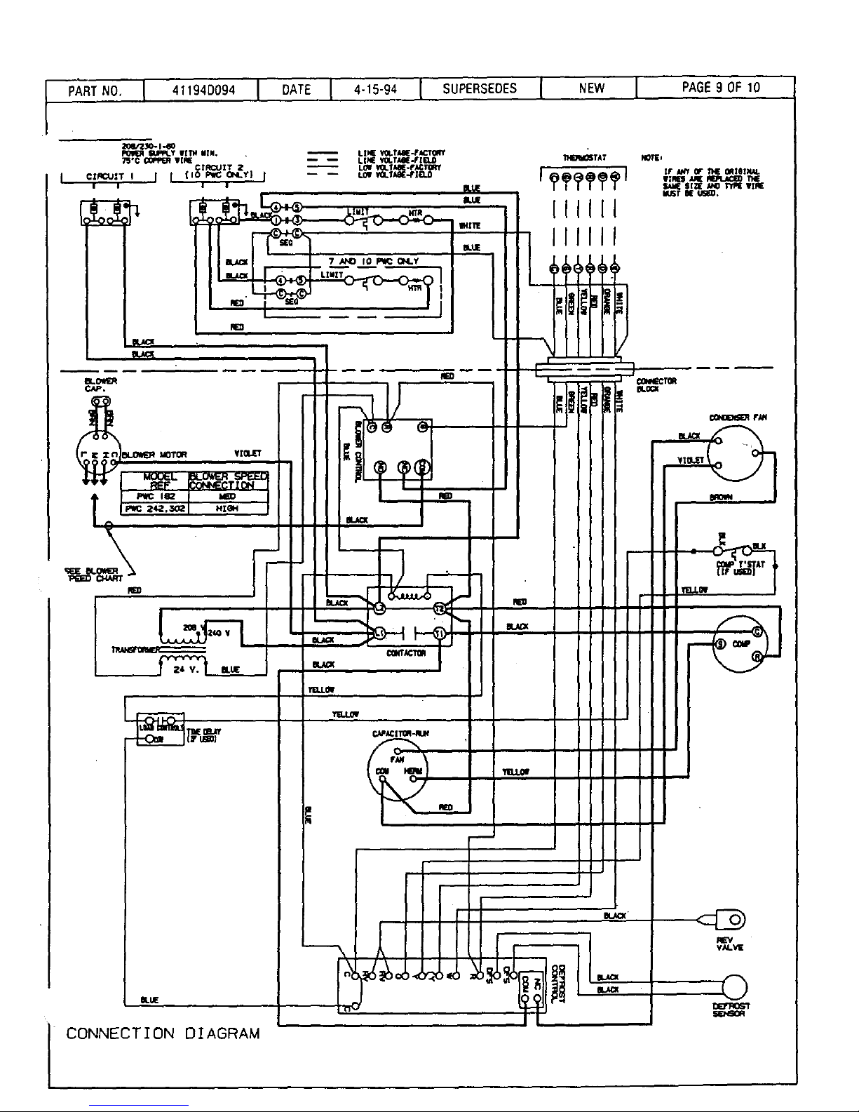
CONNECTION DIAGRAM
Page 29
I PAGE10 OF 10
1PA'_RT N0. I 411941)094 I DATE I 4-15-94 I SUPERSEDES I NEW
3Ct/'ZsO-t-60
SUPPLTWI?H¥[N.
75'€ €_ WIIaE
_ LINK; tOLTAE_'II_O
CX_Z:_zT t i _ cz_qcuzT 2 ) -- -- Lof vo.T_4[_
HZOH
Ot.UE
VXa.k'T
€_rxcTOR
aU_a_
Yn.LOW
'flg.LOw
CAPACl TIOR-RUN
BUJE
mAC=
11.10_6?AT
IIIIII
IIIIII
I
I
=lJu_
NO"_j
F AWlG_ THE CtqXOINAL
IrlRl_ _ _ T14£
SAUESIZE A_P TYPEWIRE
i_T 0£ USf_,
V_
©
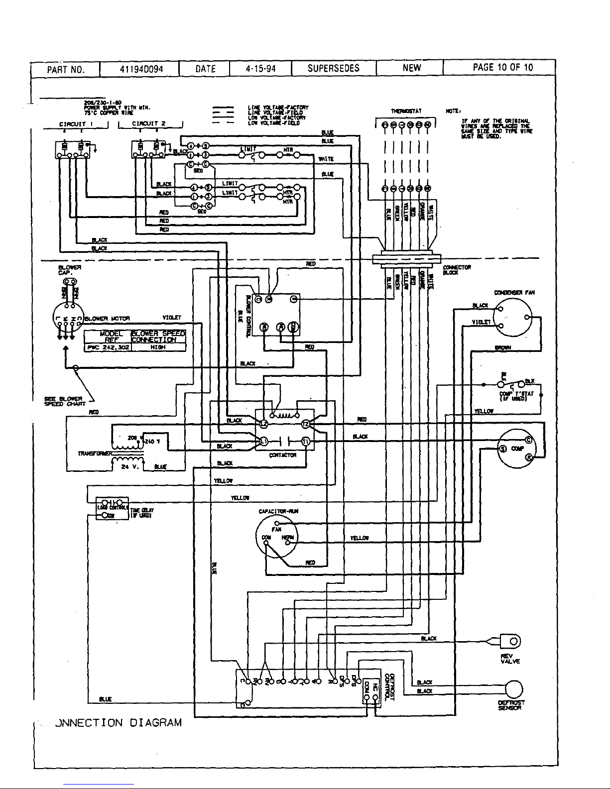
,.)NNECT I ON DIAGRAM
I
Page 30
,!
PWC
SELF CONTAINED
THRU-THE-WALL HEAT PUMP
Part No. 30790F08g Date 6-1-69
Supersedes 30790G082 Page_of 12
Installation and
Maintenance Instructions
_O,MSTP_,
Page 31
Part N_ 30790F089
$upereedes 30790G082
Date. 6-1-89
Page2__2__of 12
FORWARD
This is a self-contained heat pump designed for Installation through an exterior wall. The unit is Underwriters'
Laboratories listed under heat pumps and is in compliance with Underwriters Standard, UL 559.
The unit is also certified to the Air Conditioning and Refrigeration Institute as complying to ARI Standard 240.
To simplify the proper Installation and to assure that the unit will operate tn conformity with general ac-
cepted safety regulations, you should read carefully the instructions outlined In this manual.
Failure to comply with the Installation Instructions, Operating Instructions or Maintenance Instructions, or
Alterations of internal widng or parts not specifically outlined within this manual will void the Agency Listing's
and Manufacturer's limited warranty.
KEEP THIS MANUAL IN A SAFE PLACE FOR READY REFERENCE.
Page 32

PartNo. 307SOF089
Supersedes 30790G082
Date 6-1-89
Page _of 12
INTRODUCTION
This manual is intended to familiarize the installer, serviceman, and the user with the installation, operation
and maintenance of this thru-the-wall heat pump.
This unit is shipped from the factory in one package completely assemblied and wired. A specially designed
trap assembly is shipped, secured to the air return area in lower front of unit.
Check the rating plate to confirm heating and cooling capacities are as ordered and are as shown on the
packaging label.
When this unit is unpacked, a check should be made for any damage. If any damages are discovered, DO
NOT INSTALL THE UNIT. Notify the transportation company and make proper notation on the carders freiaht
bill. Damage claims must be filed with the carrier at once.
The manufacturer can assume no responsibility for damages which Occur in transit or for improper Opera-
tion of the unit as a result of shipping damages.
Page 33

Part No. 30?90F089 Date 6-149
Supersedes 30790G082 ,, Page _of 12
TABLE OF CONTENTS "
Page
INSTALLATION
Site Preparation ............................ 5
Condensate and Defrost Drain ................. 6
Electrical Connections ........................ 7-8
Thermostat ............................... 9
Air Filter ......... ; ...................... 9
Duct Work ............................... 9
Unit Checkout Procedure ..................... 10
OPERATION INSTRUCTIONS
Heating Operation .......................... 11
Cooling Operation .......................... 11
System Shutdown .......................... 11
MAINTENANCE AND SERVICE
Air Filter ................................. 12
Chassis Removal ........................... 12
Page 34

Part No. 307g0F089
Supersedes 30790G082
Date. 6-1-89
Page_of 12
INSTALLATION
Site Preparation
Tills unit is approved for thru-the.wall installation, with zero clearance to combustible material. The unit must
be installed within a conditioned space to prevent freezing of defrost water in trap assembly and to avoid
jacket heat loss and surface condensation problem.
This unit must be installed with the wall sleeve specified for this unit. Refer to the manufacture's specifica-
tion sheet for complete information and demensions.
Assemble the wall sleeve in accordance with the instructions furnished with each wall sleeve.
Install the wall sleeve level and square in all comers. It is to extend a minimum of 114" to 3/8" maximum
beyond finished wall to permit caulking all around the sleeve without blocking drain holes at bottom front
of sleeve.
Before installing unit, Inspect wall sleeve. Make sure the gaskets located on the inside of the outer flanges
are firmly attached to the sleeve and are not damaged. Damage or loose gaskets must be repaired before
installing unit.
The sleeve is not intended as the sole support for the thru-the-wail unit. An additional support must be pro-
vided beneath the front of the unit for adequate support, The use of vibration insulation matedai between
the unit and the support is recommended.
See Figure 1.
Wall Sleeve • Seal space between
wall sleeve and building opening
using non-hardening caulking com-
pound. The seal must be water tight+
g"x 22" rain. opening
to align with return
air opening in unit.
Hole for drain.
Ddll hole on left
or dgtht side
• through base after
unit is installed.
FIGURE 1.
Celotex, or equivalent
Plywood
Page 35

Part No. 30790F089 Date 6-1-89
Supersedes 30790G082 Page_of 12
INSTALLATION
Before sliding unit into sleeve, remove 5 screws and washers from top panel. Slide unit into sleeve until the
angle on top of the unit lines up with the top flange of the sleeve, and should almost touch. Fasten unit
to sleeve with the 5 screws and washers above.
Condensate and Defrost Drain
The condensate drain trap furnished with the unit is a copper tube assembly and is furnished with three
pieces of plastic tubing.
To install condensate drain (Reference Figure 2.), connect one of the plastic tube ends over the 5/8" O.D.
fitting welded to the center of indoor condensate drain pan and another end to.the 5/8" O.D.fitting on the
chassis base. Connect the third plastic tube end to the open drain trap,
The drain line should pitch gradually downward at least 1 inch per foot of horizontal run to open drain trap.
Be certain that plastic drain tube has free drainage and Is not cdmpad or flattened at any bend. Test drainage
by pouring water into drain pan under indoor coil and see that It Is removed rapidly through the drain tubing.
The plastic drain connection Is provided so that tt may be disconnected from the permanent drain tubing
in the building without unsoldering tn the event It becomes nceccesaary to remove the refrigeration drawer
assembly. TOTAL DEFROST DRAIN SYSTEM MUST BE LOCATED IN THE CONDITIONED AREA TO AVOID
FREEZING.
FIGURE 2.
Drain line must not
be above lowest drain
pan fitting.
i,ii_ II •
I
I
r-w
|
Indoor coil
Drain pan
Chassis base
Use hole provided
on either side of
base to exit unit.
Retum air
duct (if used)
5/8" rain. O.D. copper
or alum. drain tube
(shaded Item.
Pitch 1 In. per ft.
Installer supplied)
One 5/8" O.D. copper
trap & plastic tubes (3)
(furnished)
Alternate
route through
return air duct.
/
Open drain trap
in conditioned
space to prevent
freezing and
damage.
Page 36

PanNo. 307g0F089
Supemedes 30790G082
Date 6-1_9
Page T of 12
INSTALLATION
Electrical Connections
All wiring to unit must comply with the national Electrical Code NFPA No. 70 or local codes, where they prevail.
ANY ALTERNATION OF INTERNAL WIRING CAN VOID UNDERWRITER'S APPROVAL, ARI CER-
TIFICATION AND MANUFACTURE'S LIMITED WARRANTY.
The series and rating plates indicate the operating voltages, phase, ampacities and maximum fuse size and
electric heater ratings. Units must never be installed where voltage exceeds 110% of higher voltage indicated
on rating plate, or less than the minimum operating voltage on rating plate,
Ratings and BTU output are based on 230 V, 60 HZ supply. Voltages other than this rated voltage will alter
the BTU output of this unit. For specific ratings at voltages or frequencies other than that designated con-
tact your distributor or the manufacture.
FAILURE OF THE COMPRESSOR AS A RESULT OF OPERATION ON IMPROPER VOLTAGE VOIDS
THE COMPRESSOR REPLACEMENT WARRANTY.
Multiple power supply connections must be used when total unit amp draw Is over 48 amps. If multiple power
supply connections are used, separate fused disconnects must be Installed for each circuit between the
main panel and the supply terminals In the unit.
Circuit No. 1, terminals L1 and L2 on the terminal block Is always used to supply power to the heat pump
section. See Figure 3, 4, and 5.
Circuit No. 2, terminals L3 and L4 on terminal block (units up to 11.0 KW) or fuse block (units over 11.0
is always used to supply power to electdc heaters.
Single entry supply may be used on units, when total amp draw, (heat pump plus heaters) Is less then 48
amps, and is not In violation of prevailing electrical codes.
Units with 7.2 KW heaters or less are supplied with Internal jumpers between 1.1& 1.3, and L2 & L4 for single
entry supply. Remove jumpers between L1 & I..3and 1.2 & L4 when multiple entry supply is to be used.
Fuse and wire sizing must be in accordance with prevailing electrical codes. See Product Specification sheets
or Unit Sedes and Rating Plate for ampacities end maximum fuse.
Page 37

Part No. 30790F089
Supersedes 30790G082
Date 6-1-89
Page_ of 12
FIGURE 3.
SINGLE ENTRY SUPPLY
[]
208-230 voit
1 Ph. power supply
I
I
I
Remove internal
for multiple entry Supply.
PWC18E4.8, PWGI8E7.2
PWC24E4.8, PWC24E7.2
208-230V
1 Ph. power supply
t-_ Circuit I"_
ICircuit
I No.I No.2 I
FIGURE 4,
MULTIPLE ENTRY
SUPPLY
I
I
I
I
PWC18E9.2, PWC18E10.7
PWC24Eg.2, PVVC24ElO.7
I
r I Circuit
! No.1
208.230V
1 Ph power supply
Circuit
No. 2
FIGURE 5.
MULTIPLE ENTRY
SUPPLY
PWC18E14.7
PWC24E14.7
Page 38

Part No. 30790F089 Date 6-1-89
Supersedes 30790G082 Page_of 12
Thermostat
This unit requires special thermostat for operation. See product specification sheets or label on unit for
manufacture's part number. Install the thermostat according to directions furnished with It. Select a loca-
tion in a room having the most wall or window area exposed to the outsid_ Locate on an inside wall, away
from drafts, sunlight or any heat producing appliances. Connect thermostat wires to pigtail leads on unit
with wire nuts following wire diagrams attached to unit.
Air Filter
This unit is supplied with a permanent type high filtration filter, located in front of the indoor coil. If an In-
tallation is made in which it Is more desirable to mount the filter extedor to the unit In the return duct, the
permanent filter supplied can be used or a disposable filter may be used. If a different filter or filters are
used the minimum total filter area required is 375 eq. in. of nominal 112inch thick media, if a remote filter
is Installed, the permanent filter supplied with this unit must be removed.
Duct Work
Provide duct work sufficiently large enough to handle the air volume at the total external static pressure
not exceeding the rating of the unit published in the Product Specification sheet for the rated cooling air
volume.
Connect supply duct to top of unit using canvas connections or other flexible connection to prevent sound
transmission Into the duct system.
To connect the return duct to the unit, use e straight piece of duct 21 _" by 9".
Insert duct into return opening in bottom of unit and flange duct over existing flanges around opening In-
side unit. Make sure that all sides of the duct are flanged over to permit removal of cooling chassis If re-
quired. Use a flexible connection to attach remainder of return air duct.
Adjustments
No adjustments are required or should be attempted regarding any of the components of the heat pump
chassis and supplementary electdc heaters.
The unit should be checked to see that none of the wiring is loose or missing. The plug-in electrical connec.
tors between the cooling chassis and the main control compartment should be checked to make sure the
plugs are firmly seated and none of the wires are loose.
Page 39

Part No. 30790F089
Supersedes 30790G082
Date 6-1-89
Page 10 of 12
INSTALLATION
A. Unit Check-Out Procedure - IMPORTANT
1. Filter(s) must be clean and in place as to filter all air passing over
2. Set thermostat to "OFF" position.
3. Check that correct size fuses are installed for unit.
4. All panels must be in place.
5. Turn on main power to unit.
indoor coil,
B. Heating Check
1. Set fan switch to "AUTO".
2. Set thermostat lever to lowest temperatuf'e.
3. Set thermostat switch to "HEAT" position (if indoor ambient temperature is near or colder
than thermostat setting, heat pump will start immediately).
4. Slowly adjust thermostat to warmer temperature until first stage heat is activated (com-
pressor will start).
5. If'possible, check outdoor fan to make sure it's rotating (this is especially important If heat
pump has been installed for sometime and not running in the winter such that the outdoor
fan plenum could be clogged with snow or ice build-up).
6. Check indoor air outlet to verify indoor fan is blowing air and getting warmer.
7. Adjust thermostat lever to at least 5"F warmer temperature So that second stage heat will
activate.
8. Check indoor air outlet for increased heating (higher temperature).
C. Cooling Check
1. Set thermostat switch, to "OFF" position for minimum of 5 minutes to allow heat pump
pressures to equalize.
2. Set thermostat lever to lowest temperature for cooling
3. Set thermostat switch to "COOl." position (compressor should start unless indoor ambient
is near or colder than thermostat setting).
D. Blower Operation
1. Set thermostat switch to "OFF" position.
2. Set fan switch to "ON". Indoor fan only will operate.
3. Return fan switch to "AUTO". Indoor fan will stop.
Page 40

Part No. 30790F089
Supersedes 30790G082
Date. 6-1-89
Page 11 of 12
OPERATION INSTRUCTIONS
The following instructions are to be followed to obtain years of trouble free operation of your year-around
comfort system.
To start unit turn on main power (may have two disconnect switches). If the outdoor temperature is below
indoor temperature, the main power should be turned on 24 hours before starting unit in order to assure
no liquid refrigerant is in the compressor crankcase, and to prevent valve damage of compressor.
Operation of this unit is automatic and will provide heating or cooling depending on the setting of the
thermostat.
Heating Operation
1. Set thermostat system switch to "HEAT;',
2. Set thermostat lever to desired temperature.
3. Set fan switch to "ON" for continuous indoor blower operation or to "AUTO" for indoor
blower to cycle corresponding with thermostat cycling.
Cooling Operation
1. Set thermostat system switch to "COOU'.
2. Set thermostat lever to desired temperature.
3. Set fan switch to "ON" for continuous indoor blower operation or to "AUTO" for indoor
blower to cycle corresponding with thermostat cycling,
System Shutdown
1. For temporary or short periods of shut.down, set thermostat system to 'OFF" and fan
switch to "AUTO".
2. For a prolonged period of shut-down, set thermostat system switch to "OFF" and fan
switch to "AUTO". Tum off electdc power supply. (Two disconnect switches may supply
unit.)
Page 41

Part No. 30790F089
Supersedes 30790G082
Date, 6-1o89
Page 11 of 12
OPERATION INSTRUCTIONS
The following instructions are to be followed to obtain years of trouble free operation of your year-around
comfort system.
To start unit turn on main power (may have two disconnect switches). If the outdoor temperature is below
indoor temperature, the main power should be turned on 24 hours before starting unit in order to assure
no liquid refrigerant is in the compressor crankcase, and to prevent valve damage of compressor.
Operation of this unit is automatic and will provide heating or cooling depending on the setting of the
thermostat.
Heating Operation
1. Set thermostat system switch to "HEAT".
2. Set thermostat lever to desired temperature.
3. Set fan switch to "ON" for continuous indoor blower operation or to "AUTO" for indoor
blower to cycle corresponding with thermostat cycling.
Cooling Operation
1. Set thermostat system switch to "(_OOU'.
2. Set thermostat lever to desired temperature.
3. Set fan switch to "ON" for continuous indoor blower operation or to "AUTO" for indoor
blower to cycle corresponding with thermostat cycling.
System Shutdown
1. For temporary or short periods of shut-down, set thermostat system to 'OFF" and fan
switch to "AUTO".
2. For a prolonged period of shut-down, set thermostat system switch to "OFF" and fan
switch to "AUTO". Turn off electric power supply. (Two disconnect switches may supply
unit.)
 Loading...