

Lennox PureAir PCO-12C-2, PureAirPCO-20C-2 Installation And Maintenance Instructions Manual
Page 1
AIR CLEANERS/
FILTERS
HEALTHY CLIMATE
®
©2003 Lennox Industries, Inc.
Dallas, Texas USA
504,745M
08/2003
PUREAIR™ AIR PURIFICATION SYSTEM
PHOTOCATALYTIC OXIDATION TECHNOLOGY(PCO)
INSTALLATION AND MAINTENANCE INSTRUCTIONS FOR CASED PUREAIR™ MODELS PCO-12C-2, PCO-20C-2
General
The PureAir™ air purification system helps to significantly reduce levels of airborne volatile organic
compounds, cooking odors, common household
odors, airborne dust particles, mold spores, and
pollen in residential spaces. The PureAir™ air purification system (cased model) includes a MERV 9
pleated filter, UVA lamps, and a metal insert that is
coated with a titanium dioxide catalyst. As air enters
the system, a percentage of airborne particles and
bioaerosols, such as mold and bacteria, ranging in
size down to .3 microns, are captured by the pleated filter. The smaller airborne particles, odors, and
chemicals continue through the system. The UVA
lamp activates the catalyst on the metal insert. The
catalyst combines with water vapor in the air to form
hydroxyl radicals that destroy a percentage of the
remaining odors and chemicals.
In laboratory & field tests, we found greater than
(TVOC) within 24 hours of initial installation and
operation of the PureAir™ air purification system.
When the system is first started, it may take up to 48
hours to reduce the airborne chemicals that have
built up in your home over a long period of time.
After that period, there will be a balance between
chemicals emitted inside your home and chemicals
removed by your PureAir™ air purification system.
Please refer to the included Homeowners IAQ guide
for other measures to improve indoor air quality.
The PureAir™ air purification system is NOT intended to be used for
removal of active mold growth or continuous source of high levels
of chemicals in the air. For existing mold growth, the mold must be
appropriately removed PRIOR to installation of your PureAir™ air
purification system.
Shipping and Packing List
Package 1 of 1 contains:
1 - PureAir™ air purification system c/w:
1 - Metal cabinet, including insulated door
1 - One piece slide-in assembly (Metal Frame and
ballasts, with associated wiring.)
1 - MERV 9, 4" pleated filter
4 - Installed UVA lamps (PCO-12C)
6 - Installed UVA lamps (PCO-20C)
1 - Separately wrapped titanium dioxide metal insert
1 - Power cord
1 - Installation and maintenance instructions
1 - Homeowners IAQ Guide
1 - Warranty certificate
1 - Registration card
Unique Supplies
• Cotton gloves and cloth (to remove finger prints
from lamps.)
• Sealant: Aluminum foil duct tape or water based
mastic. (NOT silicone)
NOTICE
Possible odor emissions.
Odors may be present temporarily after initial startup, painting, cleaning, remodeling, hobby activities or
after lamp replacement.
Some occupants may notice irritation or discomfort
during this period.
WARNING
Electric shock hazard.
Can cause injury or death.
Disconnect all remote electrical
power supplies before servicing.
Access panels must be in place during the appliance operation.
If irritation or discomfort persists longer than 48
hours, unplug the PCO device and contact your
Lennox authorized dealer.
WARNING
Risk of property damage, injury, or death.
Installation, adjustments, alterations, service and
maintenance must be performed by a qualified
service technician.
212361-03 Rev. 1B 8/03
Page 2

Dimensions/Specifications
DIMENSIONS:
Model PCO-12C: 29" L x 11
(737mm x 295mm x 495mm)
Model PCO-20C: 29" L x 11
(737mm x 295mm x 606mm)
5
/8" W x 19 1/2" H
5
/8" W x 237/8" H
WEIGHT:
Model PCO-12C: 54 lbs.(24 kg.) Installed
67 lbs.(30 kg.) Shipping
Model PCO-20C: 62 lbs.(28 kg.) Installed
76 lbs.(34 kg.) Shipping
ELECTRICAL:
Model PCO-12C: 120V, 1.6 Amps, 60Hz
Model PCO-20C: 120V, 2.4 Amps, 60Hz
Line Voltage: 108V-132V (If unit operates above
128V, a reduction in lamp life on the order of 10 -
15 may occur.)
POWER CONSUMPTION:
Model PCO-12C: 192 Watts
Model PCO-20C: 288 Watts
Model PCO-12C
115/8"
191/2"
Model PCO-20C
115/8"
237/
8"
29"
29"
OPERATING ENVIRONMENT:
0°F - 140°F (-18°C - 60°C) Outside of duct.
10 -60 relative humidity. (PCO has optimal performance at 50 relative humidity.)
PLEATED FILTER EFFICIENCY:
Minimum Efficiency Rating Value - MERV 9. Tested
to ASHRAE Standard 52.2.
LISTINGS:
ETL Safety Listing Report #J99*9379-001,
Conforms to UL STD 1598, Certified to CSA STD
C22.2 NO.250.0
Specifications subject to change without notice.
Approximate Air Flow Resistance
Capacity Flow Rate Pressure Drop (inches w.g.)
(Tons)
(CFM)
PCO-12C PCO-20C
2 800 .08 .07
2.5 1000 .12 .09
3 1200 .16 .12
3.5 1400 * .15
4 1600 * .18
4.5 1800 * .21
5 2000 * .24
*Not Recommended. Excessive system pressure drop can
damage your HVAC system and reduce its performance.
2
Page 3
Installation
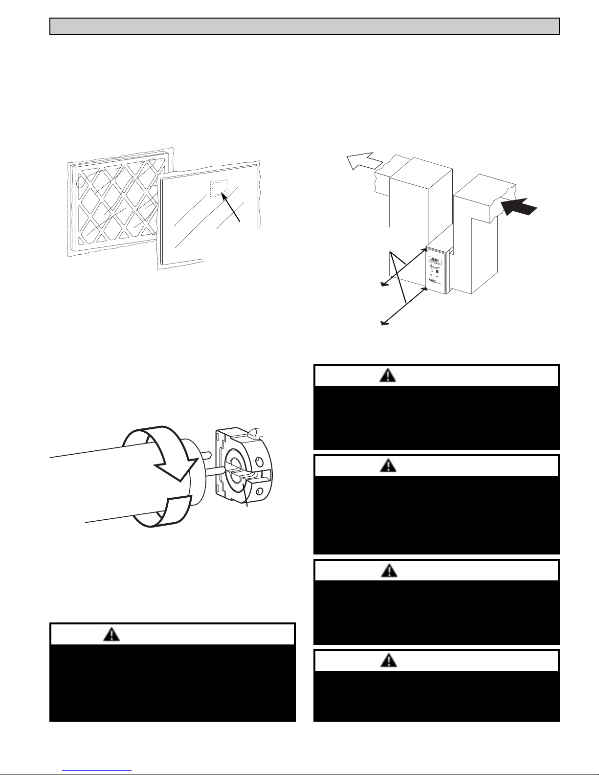
UNPACKING THE PCO-12C/20C (Fig. 1)
The MERV 9 pleated filter has been vapor barrier
packaged. The metal insert has been vacuum
packaged. All protective wrapping MUST BE
removed prior to installation and operation of
system.
Remove carbon
pouch inside metal
insert packaging.
Fig. 1 Remove and discard all wrapping and packaging
material prior to installation and operation of PCO-12C/20C.
SELECTING A LOCATION(Fig. 3)
Install the PCO-12C/20C ONLY in the return air
duct upstream of the supply blower. Allow approximately 30" of clearance in front of access door to
slide out the PCO-12C/20C assembly. This provides easier access to change the pleated filter,
metal insert, and UVA lamps.
Allow approximately
30" of clearance.
CHECKING THE LAMPS (Fig. 2)
Lamps are factory installed as shown below. Make
sure that the lamps have not become disengaged
during shipping. Use cotton gloves or cloth to
avoid fingerprints on the lamp.
Excessive force
may damage
plastic socket.
Fig.2 Verify proper installation of lamps.
CAUTION
Fig.3 Install PCO-12C/20C in the return air duct.
CAUTION
Sharp edges hazard.
Equipment sharp edges can cause injuries.
Use protective gloves when grasping equipment edges.
NOTICE
Unpacking required.
Remove all protective packing material from the
pleated filter and the titanium dioxide metal insert.
All packing material should be discarded properly
in refuse containers.
NOTICE
Clean lamps prior to installation using a cotton
cloth to remove dirt and fingerprints.
Failure to clean lamps could reduce the system's
efficiency
Lamps contain Mercury.
Ingestion or contact with mercury or mercury vapor
is hazardous to your health.
Take care when handling lamps. If lamp is broken,
avoid contact with mercury.
NOTICE
Intended for return air duct installation only.
Improper installation can damage HVAC system,
PureAir™ or other equipment and may void warranty.
3
Page 4

Installation
INSTALLATION EXAMPLES
Up-Flow
(Side Installation)
Note - At sharp turns,
turning vanes should be
installed before the PCO12C/20C.
Up-Flow
Down-Flow: Note - Due to flue
location on some down-flow furnaces,
the front of PCO-12C/20C must be
installed to side or rear of furnace cabinet. If installed in a confined space,
service clearance may be restricted.
Typical Transition: If furnace opening
does not match up to the PCO opening, a sheet
metal transition should be used. Transition
must be planned for each job. Reduction
should not be more than 4 inches per linear
foot, approximately 20 angular degrees.
Horizontal
INSTALLING THE CABINET (Cont'd)
High Humidity Environments: Wrapping cabinet with
2" foil faced insulation (foil on the outside) around the
case (excluding the insulated door) will prevent condensation on the sides of the PureAir™ case.
INSTALLING THE ASSEMBLY (Fig. 4)
1. Check lamps for proper seating in sockets.
2. Slide the PCO-12C/20C assembly into cabinet,
using the cabinet rails as a guide.
3. Slide the pleated filter into the rails on the air
inlet side of the PCO-12C/20C assembly. Verify
proper air flow direction through pleated filter.
4. Slide metal insert into rails downstream of UVA
lamps so that 1/2” flange is toward back of cabinet.
5. Install access door using provided screws. Be
sure unused plug opening is covered with black
hole plug.
6. Plug one end of provided power cord into
receptacle on PCO-12C/20C and the other end
into a 120V power receptacle.
IMPORTANT: Route power cord away from
traffic areas where the cord may become a
safety hazard.
7. Verify that the lamps are illuminated.
INSTALLING THE CABINET
Oil on metal ducts can cause odors. Wash all new
transitions and duct surfaces with mild soap and
water to remove oils prior to installation. Connect the
PCO-12C/20C cabinet to the return air side of the air
handling unit with field provided sheet metal screws,
rivets, or appropriate method. Be sure to orient cabinet to airflow direction as indicated on label inside
cabinet. Fasten return air duct to other side of PCO12C/20C cabinet. Seal all joints between the cabinet,
air handling unit, and ducting with aluminum foil
tape or water based mastic. Ducts and air handler(s)
should be sealed to prevent contamination from
unconditioned spaces (such as basements,
garages, or attics).
Optionally, the cabinet can be strap-mounted from the
ceiling. When drilling screw holes in the cabinet for
straps, be sure to locate them where they do not interfere with the insertion of the PCO-12C/20C assembly.
CAUTION
Airflow
direction.
Fig. 4 Slide PCO-12C/20C assembly with provided pleated
filter and metal insert into the PCO-12C/20C cabinet.
NOTICE
Do not use any form of silicone sealant.
Use of silicone-based products will reduce the effectiveness or damage the titanium dioxide coatings.
NOTICE
Ultraviolet (UV-A) radiation risk.
Prolonged exposure may cause skin or eye damage.
Avoid prolonged (weeks) exposure to skin or eyes.
Oil on metal ducts can cause odors
Wash all new transitions and duct surfaces with mild soap
and water to remove oils prior to installation.
4
Page 5

Installation
Operation
WIRING INSTRUCTIONS (See wiring diagrams)
The PCO-12C/20C must be wired in accordance
with national and local codes.
IMPORTANT: To ensure UVA lamps life, power
MUST remain on to PCO-12C/20C at all times. Do
not interlock with air handler blower.
MODEL PCO-12C WIRING DIAGRAM
1. Door on unit must be secured in place prior to
operation.
2. Lamps to remain illuminated continuously except
during service and maintenance.
3. For optimal odor control, fan should remain on
continuously (i.e. run with thermostat fan setting in
the “ON” position, not the “Auto” position.)
Running fan continuously during cooling operation may result in higher humidity. If this occurs,
set thermostat in the “Auto” position during cooling operation.
4. For those air handlers that do not have a continu-
ous "Low Fan Speed " mode, an additional blower
relay will need to be installed. Use Lennox blower
relay part number 45H03. Lennox utilizing the
Lennox Surelight™ heating control do not require
the use of an additional blower relay.
MODEL PCO-20C WIRING DIAGRAM
WARNING
Electric shock hazard.
Can cause injury or death.
Disconnect all remote electrical
power supplies before servicing.
Access panels must be in place during the appliance operation.
WARNING
Risk of Carbon Monoxide poisoning.
Can cause injury or death.
Do not operate without access panel in
place. Operation of this equipment
without the access panel in place may
cause gas fumes from the heating system to be drawn into occupied spaces.
5
Page 6

Maintenance
The PCO-12C/20C has three components that will
require maintenance: MERV 9 pleated filter, metal
insert, and UVA lamps.(For replacement part numbers refer to Replacement Parts section in these
instructions. PCO-12C/20C performance will be
dramatically reduced if the required maintenance
is not performed on these three components.)
MERV 9 PLEATED FILTER
The pleated filter should be replaced every 12
months. More frequent filter changes may be
required in situations with high dust or dirt loads.
1. Unplug the power cord and remove the access
door.
2. Partially slide out the PCO-12C/20C assembly.
3. Remove the pleated filter and replace with the
same MERV 9 filter. (Performance of PCO12C/20C will be dramatically affected if improper
filter is installed.)
4. Slide assembly back into cabinet and install access
door.
5. Reconnect power cord.
METAL INSERT/LAMP REPLACEMENT(Cont'd)
6. Install new metal insert.
7. Slide assembly back into cabinet and install
access door.
8. Reconnect power cord.
9. Verify that the lamps are illuminated.
Note: DO NOT WASH metal insert. Washing will
destroy the titanium dioxide catalyst that coats the
insert surface.
Note: If the system has been operated for a period
of time without the lamp(s) being illuminated (such
as at startup or with a failed lamp), an odor may
occur when lamps are (re)started. This symptom is
considered to be typical and should only be temporary. In the event that an odor does occur, it
should subside and dissipate within 12 hours of
full operation. If this odor persists longer than 48
hours, you should unplug the PCO and contact
your Lennox authorized dealer.
6. Verify that the lamps are illuminated.
METAL INSERT & LAMP REPLACEMENT
Replace metal insert and lamps* every 24 months.
Replace insert more frequently if you notice a significant drop in odor removal efficiency.
If you find that you need to replace the insert more
frequently than every 24 months, consider source
reduction and/or ventilation to reduce the levels of
contaminants in your home (see Homeowners IAQ
Guide for additional recommendations).
* Lamps will continue to glow at the end of the 24
months. However, their output efficiency will have
degraded to the point that they must be replaced to
assure effective performance of your PureAir™ unit.
1. Unplug the power cord and remove the access
door.
2. Slide out PCO-12C/20C assembly.
3. Remove metal insert.
4. Twist/rotate each lamp approximately 1/4 turn to
remove from sockets.
5. Install new lamps making sure to snap them
completely into the sockets and twist/rotate
lamp approximately 1/4 turn. Use gloves or cloth
to avoid fingerprints on lamps. (See page 3.)
CAUTION
Ultraviolet (UV-A) radiation risk.
Prolonged exposure may cause skin or eye damage.
Avoid prolonged (weeks) exposure to skin or eyes.
NOTICE
Clean lamps prior to installation using a cotton
cloth to remove dirt and fingerprints.
Failure to clean lamps could reduce the system's
efficiency.
CAUTION
Lamps contain Mercury.
Ingestion or contact with mercury or mercury vapor
is hazardous to your health.
Take care when handling lamps. If lamp breaks,
avoid contact with mercury.
6
Page 7

Replacement PartsMaintenance
LAMP CHECKOUT (Does not illuminate.)
1. Check power cord for 120V power.
2. Unplug power cord and remove access door.
3. Slide out assembly and remove pleated filter or
metal insert.
4. Check lamps for proper connection in sockets.
5. Exchange non-working lamp with one of the
working lamps. If the new lamp operates normally, replace defective lamp.
6. If steps 1 through 5 pass inspection then the ballast
may be at fault. Ballast must be replaced with an
approved ballast by a qualified service technician.
LAMP DISPOSAL
Hg-LAMP CONTAINS MERCURY.
Manage in accord with disposal laws.
Refer to www.lamprecycle.org or call 1-800-9-LENNOX.
CAUTION
Lamps contain Mercury.
Ingestion or contact with mercury or mercury vapor
is hazardous to your health.
Take care when handling lamps. If lamp breaks,
avoid contact with mercury.
No. Description PCO-12C-2 PCO-20C-2
Complete PureAir™ System 75X69 75X61
1 Cabinet 75X72 75X65
2 Assembly 75X70 75X62
3 Access Door 93X39 75X64
4 Electrical Socket 75X77 75X77
5 UVA Lamp 10M35(4) 10M35(6)
6 Lamp Socket 49M00 49M00
7 Ballast 56M12 56M12
8 Titanium dioxide coated metal insert 75X73 75X66
9 MERV 9 pleated filter 75X74 75X67
Power Cord (Not Shown) 49M48 49M48
Contact your local Lennox dealer to order replacement parts.
For the Lennox dealer nearest you, dial 1-800-9-LENNOX.
Visit us at http://www.Lennox.com
PROPER CLEAN-UP TECHNIQUE IN CASE OF
LAMP BREAKAGE
●
Wear protective gloves, eyewear and mask.
●
Sweep the broken glass and debris into a plastic bag,
seal the bag, and dispose of properly. Contact your
local waste management office for proper disposal.
●
Do not use a vacuum cleaner. Do not incinerate
.
Model PCO-12C Exploded View
Model PCO-20C Exploded View
1
2
3
4
5
6
7
8
9
7
Page 8

Troubleshooting
Service Flow Chart PCO-C
Start
Check inspection port
to see if lamps are lit
Are
Are
Lamps
Lamps
Lite?
Lit?
Yes
Continue with
maintenance per unit
instruction manual
End
No
Do you have
120V to
PCO?
Yes
Unplug PCO power
and immediately
plug back in
Did
Lamps
Light?
No
Check all electrical
connections, bulbs, and ballast.
Replace any burned out or
damaged components and plug
unit in.
No
Yes
Check power supply.
(Breakers, Plug, Electrical
wiring) Repair electrical and
plug unit in.
Continue with
maintenance per unit
instruction manual
Yes
Are
Lamps
Lit?
No
End
Are
Lamps
Lit?
NO
Replace
Assembly
End
Yes
Continue with
maintenance per unit
instruction manual
8
End
 Loading...