

Page 1
OPERATION
MANUAL
www.lennoxcommercial.com
1
Page 2
2
Page 3

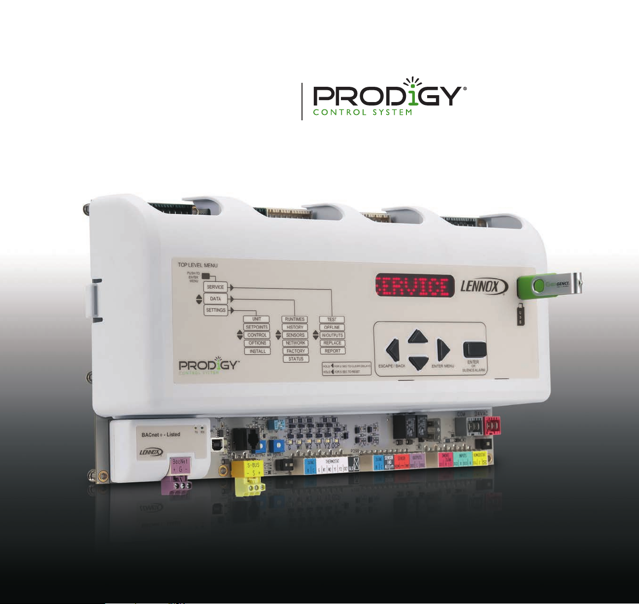
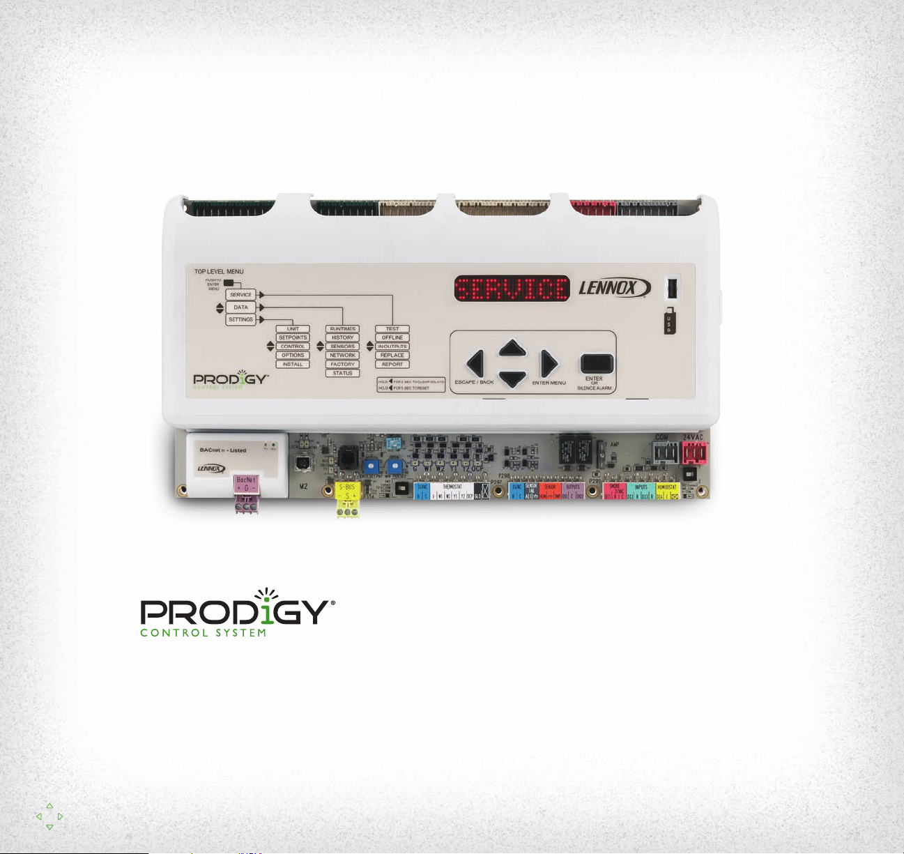
The Prodigy® control system is the latest example of Lennox’ commitment
to advanced HVAC technology. Standard on every Strategos
®
rooftop unit,
the Prodigy control system makes setup, troubleshooting and servicing
easier than ever.
The Prodigy control system includes:
• Prodigy unit controller
• SmartWire™ system
• Optional Prodigy BACnet module (BTL certified)
®
• Optional Prodigy LonTalk
module (LonTalk certified)
www.lennoxcommercial.com
3
3
Page 4
NAVIGATION
www.lennoxcommercial.com
415
Page 5

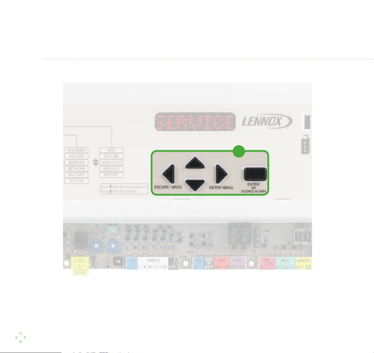
1. Navigation is performed by using the arrowed keys and the
enter button
• To reset the Prodigy® unit controller, press the left arrow and
hold for 5 seconds
— You will now be at the beginning of the menu structure
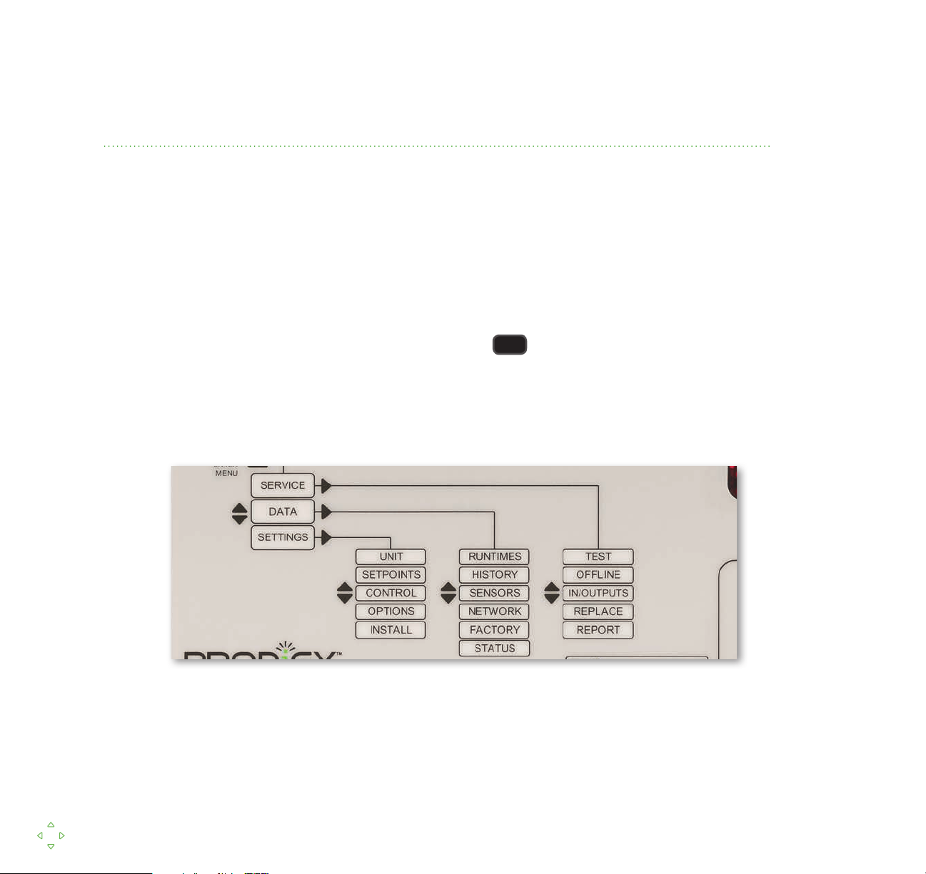
• Press the enter or right arrow to go into the sub menus:
Navigation
Display Service Data Settings
SERVICE
UNIT
SETPOINTS
CONTROLS
OPTIONS
INSTALL
• Press the down arrow until you see
RUNTIMES
HISTORY
SENSORS
NETWORK
FACTORY
STATUS
TEST
OFFLINE
IN/OUTPUTS
REPLACE
REPORT
DATA
• To exit the menu structure, press the left arrow
— Press the left arrow again to return to the Display mode.
www.lennoxcommercial.com
SmartWire
System
5
5
™
Page 6
DISPLAY
• Display shows the controller’s current state
— It will show either the current mode of operation or an alarm/
• To exit the display mode, press enter
• You are now in the menu structure
• Notice that the first level of the menu structure is located on the controller
status message
English, French or Spanish language can be selected.
www.lennoxcommercial.com
6
Page 7

ALARMS
The Prodigy® unit controller displays alarms in descriptive, actionable text.
• To simulate an alarm, press the left arrow until you are in the
display mode
• Flip down the switch to the right of the controller labeled Compressor
1HP (s4). It is located on the green trainer board next to the lower right
corner of the gray M2
Navigation Display Service Data Settings
• This will show the alarm for a high-pressure switch trip for Compressor 1
• To silence the alarm, press enter
• To turn off the alarm, simply flip the switch (S4) back to the up position
SmartWire
System
www.lennoxcommercial.com
7
7
™
Page 8
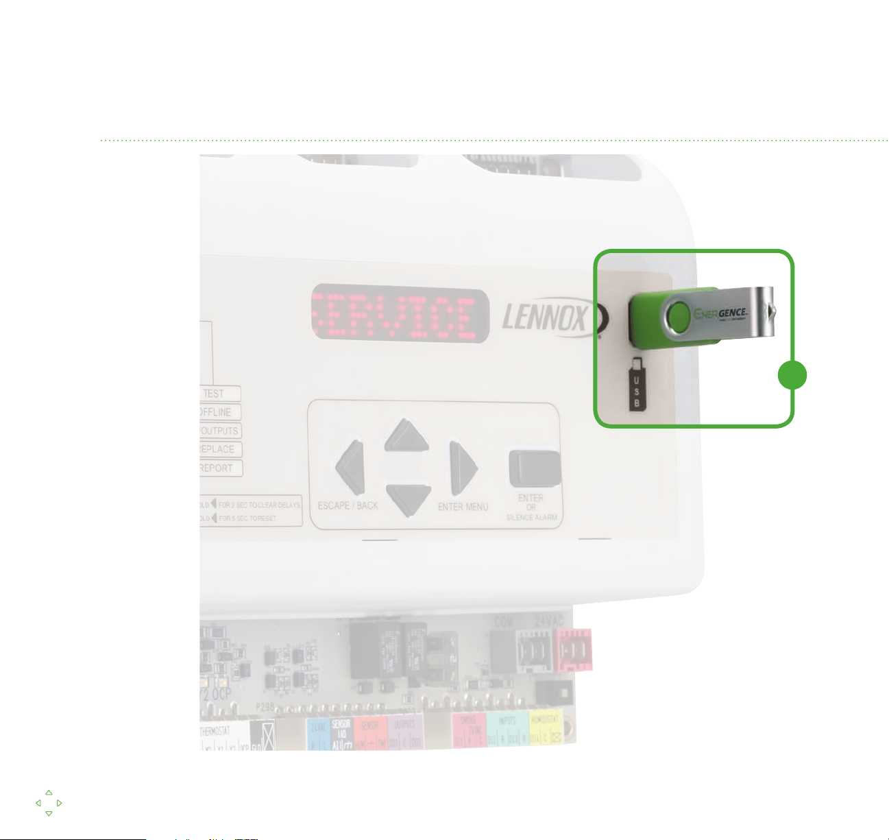
USB SERVICE REPORTS
www.lennoxcommercial.com
819
Page 9

1. The Prodigy® controller’s USB port can download service reports
• To generate a report, insert a USB memory stick into the USB port
then press enter
Navigation Display Service Data Settings
• With displayed, press enter to write
REPORT
the report
• The display will show it is writing the report and then indicate when
it is complete
• The report will be saved to the memory stick with a file name
based on the unit’s serial number
• This report can be transferred to any computer via the
memory stick
www.lennoxcommercial.com
SmartWire
System
9
™
Page 10

=========================================================================================
USB SERVICE REPORT
=========================================================================================
Service Date
Service Time
Serial No. 5609K00002
M2 Version 7.06.00
DB1 Version
Unit No.
Sbus Address
BACnet Address
CAT No.
MODEL NO.
COOLING
Status
=========================================================================================
Runtime Data
Total Power On
Before Install
Filter
Belt
Blower
Compressor 1
7/4/2010
3:15:00
1.06.00
2
2
2
36L87
Compressor 2
Compressor 3
Compressor 4
Outdoor Fan 1
Outdoor Fan 2
Outdoor Fan 3
Outdoor Fan 4
Outdoor Fan 5
Outdoor Fan 6
Heat Stage 1
=========================================================================================
Sensor Data
LGH036H4ES1Y
79 CYCLES
1832 HRS
2040 HRS
1063 HRS
1162 HRS
46 HRS
0 HRS
0 HRS
0 HRS
14 HRS
0 HRS
0 HRS
0 HRS
0 HRS
0 HRS
5 HRS
0 HRS
15 HRS
0 HRS
MENU TO CLEAR LOCKOUTS.
CHARGE, FILTERS, AIR FLOW. COIL
ALARM(5) FILTER S27 REPLACE FILTER OR CHECK FILTER
SWITCH S27
286 HRS
Heat Stage 2
Reheat
Free Cooling
UV Lamp
=========================================================================================
Alarm/Status Log
2 HRS
OAT : 100 degF
RAT : 85 degF
DAT : 86 degF
ZAT : 83 degF
RH : 60 %
CO2 : 415 ppm
23 ALARM(23) STRIKE 3 ON COMP 1 S87 COMP LOCKOUT.
CHECK CHECK CHARGE, FILTER, AIR FLOW, COIL, USE SERVICE
( 23) 7.04.2010 1:05:00
22 ALARM(22) COMP 1 LOW PRESS S87 COMP OFF. CHECK
( 22) 7.04.2010 1:00:00
( 5) 6.30.2010 21:05:00
=========================================================================================
END OF REPORT
---------
---------
---------
131 CYCLES
66 CYCLES
--------0 CYCLES
0 CYCLES
32 CYCLES
2 CYCLES
0 CYCLES
0 CYCLES
0 CYCLES
0 CYCLES
17 CYCLES
16 CYCLES
13 CYCLES
1608 CYCLES
---------
=========================================================================================
Sensor Data
=========================================================================================
Alarm/Status Log
( 22) 7.04.2010 1:00:00
( 5) 6.30.2010 21:05:00
=========================================================================================
END OF REPORT
1
=========================================================================================
USB SERVICE REPORT
=========================================================================================
Service Date
Service Time
Serial No.
M2 Version
DB1 Version
Unit No.
Sbus Address
BACnet Address
CAT No.
MODEL NO.
Status COOLING
=========================================================================================
Runtime Data
Outdoor Fan 2 0 HRS 2 CYCLES
Outdoor Fan 3 0 HRS 0 CYCLES
Outdoor Fan 4 0 HRS 0 CYCLES
Outdoor Fan 5 0 HRS 0 CYCLES
Outdoor Fan 6 0 HRS 0 CYCLES
Heat Stage 1
Heat Stage 2
Reheat 2 HRS 13 CYCLES
Free Cooling
UV Lamp
OAT : 100 degF
RAT : 76 degF
DAT : 57 degF
ZAT : 77 degF
RH : 50 %
CO2 : 415 ppm
( 23) 7.04.2010 1:05:00
4:23:00
5609K00002
Total Power On 1832 HRS 80 CYCLES
Before Install 286 HRS --------Filter 0 HRS ---------
Belt 1063 HRS ---------
Blower 1162 HRS 131 CYCLES
Compressor 1
Compressor 2
Compressor 3
Compressor 4
Outdoor Fan 1 14 HRS 32 CYCLES
0 HRS 0 CYCLES
0 HRS --------0 HRS 0 CYCLES
0 HRS 0 CYCLES
5 HRS 17 CYCLES
0 HRS 16 CYCLES
15 HRS 1608 CYCLES
0 HRS ---------
23 ALARM(23) STRIKE 3 ON COMP 1 S87 COMP LOCKOUT.
CHECK CHECK CHARGE, FILTER, AIR FLOW, COIL, USE SERVICE
MENU TO CLEAR LOCKOUTS.
22 ALARM(22) COMP 1 LOW PRESS S87 COMP OFF. CHECK
CHARGE, FILTERS, AIR FLOW. COIL
ALARM(5) FILTER S27 REPLACE FILTER OR CHECK FILTER
SWITCH S27
2
www.lennoxcommercial.com
10
Page 11

USB SERVICE REPORTS
The reports at left are an example of a service call.
1. The first report shows the status of a unit with a faulty compressor and
dirty filter
• The sensor data illustrates the issue
2. The second report shows the same unit with a new compressor
and filter
Navigation Display Service Data Settings
• Notice the new sensor readings and the reset runtime information
SmartWire
System
www.lennoxcommercial.com
11
11
™
Page 12

USB PROFILES
www.lennoxcommercial.com
12
Page 13

You can also save a unit profile which can be uploaded to another similar unit.
• To save or upload a unit profile, insert a USB memory stick in the
USB port
Navigation Display Service Data Settings
• Press enter when the screen reads then scroll
down to and press enter
PROFILES
USB
• The controller will automatically check to see if there is a profile that
matches the unit
• If there is a profile saved to the memory stick with a matching cat
number, the controller will ask to upload it
• This will instantly upload all setpoints to the unit that are saved to
the profile
• If there is no profile saved, the controller will ask if you want to save
the unit’s profile
SmartWire
System
www.lennoxcommercial.com
13
13
™
Page 14

SELF-TEST
The Prodigy® unit controller features a self-test function. This allows the user to
individually test critical component operation.
• First, navigate to the menu and press enter
• Then, press enter again to access the menu
• Press the down arrow to find and press enter
• Then select either an individual compressor or stage (L or H)
• The controller will turn on just that compressor (stage)
• It will then return the RAT and DAT as a check of correct operation
SERVICE
TEST
COOL
www.lennoxcommercial.com
14
Page 15

REPLACE
The replace function is used to reset component runtime information. To
demonstrate, we will use a filter replacement.
Navigation Display Service Data Settings
• First, navigate to the menu and press enter
• Press the down arrow to scroll to and
press enter
• Press enter on which should be the first category
• To reset the filter runtime, press enter
• This resets the filter runtime, which should be done after every
filter change
SERVICE
REPLACE
FILTER
SmartWire
System
www.lennoxcommercial.com
15
15
™
Page 16

RUNTIMES
www.lennoxcommercial.com
16
Page 17

The Prodigy® unit controller contains runtime information on all key components.
Navigation Display Service Data Settings
• Navigate to the menu and press enter
• Press enter again on to access the menu
DATA
RUNTIMES
• You can scroll through all the runtimes using the up and
down arrows
• Press the left button twice to return to the menu
DATA
SmartWire
System
www.lennoxcommercial.com
17
17
™
Page 18

HISTORY
You can also view the history of alarm and status messages.
• From the screen, press enter and scroll
to and press enter
HISTORY
• Press enter on the screen
• The Prodigy® unit controller will display the last five alarms
• Press the left button three times to return to
the screen
DATA
DATA
ALARMS
www.lennoxcommercial.com
18
Page 19

SENSOR DATA
The Prodigy® unit controller can also display important sensor data.
Navigation Display Service Data Settings
• Once on the screen, press enter and scroll
to then press enter
• You can scroll through all the sensors and their current readings
• This data can be critical in diagnosing a problem
• Press the left button twice to return to the menu
SENSORS
DATA
DATA
SmartWire
System
www.lennoxcommercial.com
19
19
™
Page 20

SETPOINTS
www.lennoxcommercial.com
20
Page 21

Changing setpoints on the Prodigy® unit controller is quick and easy.
Navigation Display Service Data Settings
• First, navigate to the menu and press enter
• Press the down arrow to scroll to the menu
SETTINGS
SETPOINTS
and press enter
• Press enter to view the setpoints
• Press enter to change the cooling setpoint
COOLING
OCCUPIED
• Use the up and down arrows change the setpoint
• Press enter to set the value
SmartWire
System
www.lennoxcommercial.com
21
21
™
Page 22

SMARTWIRE™ SYSTEM
1
www.lennoxcommercial.com
22
Page 23

The SmartWire™ system is designed to simplify field wiring and sensor
installation.
1. Advanced connectors are color-coded, labeled and keyed to prevent
miswiring and ensure units are installed and set up correctly
• The wire-coloring scheme is standard across all units
• Each connection is intuitively labeled to simplify troubleshooting
Navigation Display Service Data Settings
SmartWire
System
www.lennoxcommercial.com
23
™
Page 24

SOLUTIONS FOR CUSTOMIZED COMFORT
Don’t just choose a Lennox® product…choose a Lennox Commercial Comfort System. These complete
packages of HVAC solutions provide tools to create a healthy and comfortable environment.
Packaged Units
• Strategos® Rooftop Units
•
Energence® Rooftop Units
•
Landmark® Rooftop Units
Split Systems
• S-Class™ Air Conditioners/
Heat Pumps
•
T-Class™ Air Conditioners/
Heat Pumps
• Air Handlers
• Indoor Coils
(64W34)-01/18
For a complete list of the registered and common law trademarks owned by Lennox Industries Inc., please visit www.lennox.com.
Heating
• T-Class Unit Heaters
• Unit Heaters
• Duct Furnaces
• Furnaces
Commercial Controls
• Prodigy® Control System
•
L Connection® Network
•
Systems Integration Solutions
• Commercial Thermostats
© 2018 Lennox Industries Inc.
Visit us at www.lennox.com, or contact us at 1-877-726-0024
Indoor Air Quality
• Humiditrol®
Dehumidification System
•
Demand Control Ventilation
• Energy Recovery Systems
• Air Filters
• UVC Germicidal Lights
Litho U.S.A.
PC67865
 Loading...