

Page 1

INSTALLATION MANUAL
For correct installation, read this manual before starting installation.
This manual may be subject to change without notice for purpose of improvement.
CEILING AND FLOOR TYPE
AIR CONDITIONER
Page 2

CONTENT
Installation precaution...........................................................................1
Installation place......................................................................................1
Accessories.................................................................................................2
Indoor unit installation.........................................................................3
Install the connecting pipe................................................................7
Connect the drain pipe..........................................................................9
Wiring.............................................................................................................10
Test operation...........................................................................................15
Page 3
There is enough room for installation and
maintenance.
The ceiling is horizontal, and its structure
can endure the weight of the indoor unit.
The air outlet and the air inlet are not impeded, and the influence of external air is
the least.
The air flow can reach throughout the room.
The connecting pipe and drainpipe could
be extracted out easily.
There is no direct radiation from heaters
1
To install properly, please read this manual at
first.
The air conditioner must be installed by qualified persons.
When installing the indoor unit or its tubing,
please follow this manual as strictly as possible.
When all the installation work is finished, please turn on the power only after a thorough
check.
No further announcement if there is any change of this manual caused by product improvement.
Note: The installor should illustrate to users
how to correctly use and maintain the air-conditioner, as well as remind users to carefully
read and keep both Installation Manual and
Owner's Manual well.
INSTALLATION PRECAUTION
The Indoor Unit
INSTALLATION PLACE
Location in the following places may cause
malfunction of the machine. (If unavoidable,
please consult your local dealer.)
a. There exists petrolatum.
b. There is salty air surrounding(near the coast).
c. There is caustic gas(the sulfide, for example)
existing in the air (near a hot spring).
d. The Volt vibrates violently(in the factories).
e. In buses or cabinets.
f. In kitchen where it is full of oil gas.
g. There is strong electromagnetic wave existing.
h. There are inflammable materials or gas.
i. There is acid or alkaline liquid evaporating.
j. Other special conditions.
Cautions
Notes Before Installation
1. Select the correct carry-in path.
2. Move this unit as originally packaged as
possible.
3. If the air conditioner is installed on a metal
part of the building, it must be electrically
insulated according to the relevant stand ards to electrical appliances.
4. Installation work must be performed in ac cordance with the national wiring Stand ards by authorized personnel only.
NOTE:
Remark per EMC Directive 89/336/EEC
For to prevent flicker impressions during the start of the compressor (technical process),
following installation conditions apply.
1. The power connection for the air conditioner has to be done at the main power distribution.
The distribution has to be of a low impedance, normally the required impedance reaches
a 32A fusing point.at
2. No other equipment has to be connected with this power line.
3. For detailed installation acceptance, please refer to your contract with the power supplier
restrictions do apply for products like washing machines, air conditioners or electrical if
ovens.
4. For power details of the air conditioner, refer to the rating plate of the product.
5. For any question contact your local dealer.
Page 4
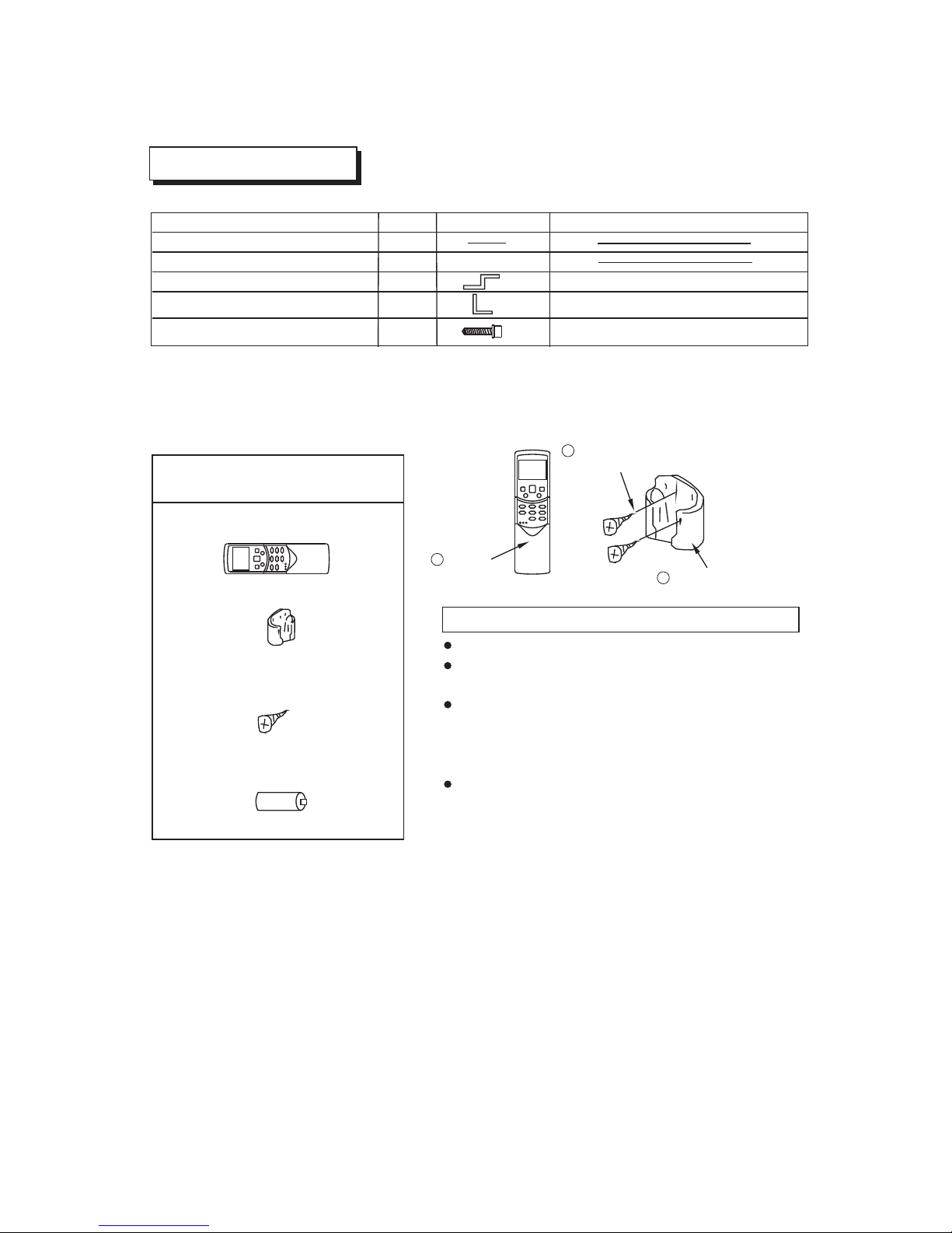
1. Remote controller..................1
2. Frame...................................1
3. Mounting screw
(ST2.9x10-C-H).....................2
4. Alkaline dry batteries(AM4)
...............................................2
Remote controller & Its Frame
1
2
3
Remote
controller
Remote controller
holder
Mounting screw B
ST2.9x10-C-H
Never throw or beat the controller.
Before installation, operate the remote controller
to determine its location in a reception range.
Keep the remote controller at least 1m apart from
the nearest TV set or stereo equipment. (It is
necessary to prevent image disturbances or
noise interferences.)
Do not install the remote controller in a place
exposed to direct sunlight or close to a heating
source, such as a stove.
Note that the positive and negative poles are
in right positions when loading batteries.
Cautions on remote controller installation
ACCESSORIES
2
1
1
2
Name of Accessories
Owner's manual
Installation manual
Q'ty
(This manual)
Qutline
Usage
Hook
For wall mountin g installation
Hanging arm
2
For ceiling inst allation
Tapping screw
4
For Hook Install ation
Page 5
3
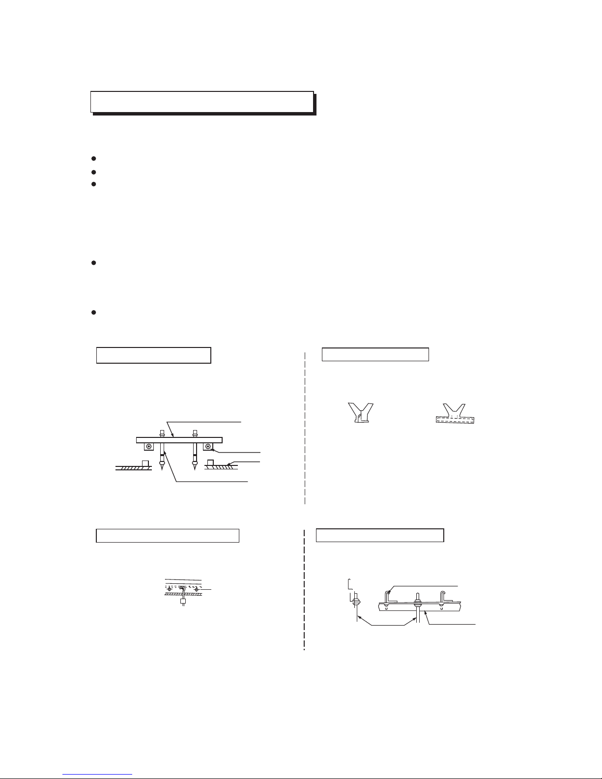
INDOOR UNIT INSTALLATION
Carry out the pipe and line operation in the ceiling after finishing the installation of the main
body. While choosing where to start the operation, determine the direction of the pipes to
be drawn out. Especially in case there is a ceiling, position the refrigerant pipes, drain pipes,
indoor & outdoor lines to the connection places before hanging up the machine.
The installation of hanging screw bolts.
Wooden construction
Installing f10 hanging screw bolts. (4 bolts)
Please refer to the following figure for the distance measurement between the screw bolts.
Please install with f10 hanging screw bolts.
The handling to the ceiling varies from the constructions, consult the construction personnels for the specific procedures.
1. The size of the ceiling to be handled ... ... do keep the ceiling flat. Consolidate the roof
beam for possible vibration.
2. Cut off the roof beam.
3. Strengthen the place cut off, and consolidate the roof beam.
Put the square timber traversely over the
roof beam, then install the hanging screw
bolts. (Refer to Chart 1)
Chart 1
Timber over the beam
Roof beam
Hanging screw bolts
Ceiling
New concrete bricks
(Blade shape insertion)
(Slide insertion)
Chart 2
Inlaying or embedding the screw bolts.
(Refer to Chart 2)
Install and use directly the supporting angl
steel. (Refer to chart 4)
e
For Original concrete bricks
Use embedding screw bold, crock and stick
harness. (Refer to Chart 3)
Steel roof beam structre
Steel bar
Hanging screw bolt
Hanging bolts
Supporting
angle steel
Embedding screw bolt
Chart 3
Chart 4
(Pipe hanging and embedding
screw bolt)
Page 6

4
Wall Mounting Installtion
Chart 5
E. Connecting point of
refrigerant pipe
(D. gas side)
D. Connecting point of
refrigerant pipe
(E. Liquid side)
Drain point
Hook
Chart 6
Was he r
1.Fix the hook with tapping screw onto the wall.(Refer to Chart 6)
2.Hang the indoo r unit on the hook.
Tapping s cr ew
<6mm
Hook
Page 7

Chart 8
5
Ceiling Installation
Chart 7
1.Remove the sid e board and the grille.(Refer to Cha rt 8)
Side bo ar d
Screw nut
Washer
Hanging
screw bolt
Hanging arm
Chart 9
20~25mm
Mount in g bo lt (max. 40 mm )
2.Locate the han ging arm on the hanging screw bolt.( Refer to Chart 9)
Prepare the moun ting bolts on the unit.( Refer to Char t 10)
Chart 10
8~13mm
Hangi ng a rm
Grill e
(For models 4800 0 and 60000 Btu/h, do not remove the gri lle.)
Page 8

6
Type
( )
Btu/h
18000-24000Btu/h
36000Btu/h
A
B
D
48000-60000Btu/h
Note:The dimension of 18000Btu/h and 24000Btu/h are the same
The dimension of 48000Btu/h and 60000Btu/h are the same
D. Connecting point of
refrigerant pipe
(D.gas side)
Drain point
E. Connecting point of
refrigerant pipe
(E. Liquid side)
The dimension of the unit
E
F G
Chart 11
3.Hang the unit on t he hanging arm by sliding backward . Securely tighten
the mounting bol ts on both sides.(Refer to Chart 9)
H
C
ATTENTION:
which may differ from the unit you purchased.
The figures above are based on model with 18000Btu/h as rated capacity,
990
660
206
505 506
907
200
203
1280
660 206
795 506
1195
200
203
1670
680
244 1070
450
1542 200 240
Hangi ng a rm
Mount in g bo lt
Hanging
screw bolt
Downw ar d de cl ivity
Lower b et we en ( 1-2)/ 10 0
Page 9

INSTALL THE CONNECTING PIPE
Check whether the height drop between the indoor unit and outdoor unit, the length of
refrigerant pipe, and the number of the bends meet the following requirements:
The max height drop...................................................................................................20m
(If the height drop is more than 10m, you had better put the outdoor unit over above the
indoor unit.)
The length of refrigerant pipe.......................................................................less than 30m
The number of bends....................................................................................Less than 15
Do not let air, dust, or other impurities fall in the pipe system during the time of installation.
The connecting pipe should not be installed until the indoor and outdoor units have been
fixed already.
Keep the connecting pipe dry, and do not let moisture in during installation.
1) Connect the indoor unit at first, then the outdoor unit.
,
Bend the tubing in proper way. Don t harm them.
The Procedure of Connecting Pipes
1. Measure the necessary length of the connecting pipe, and make it by the following way.
Daub the surfaces of the flare pipe and the joint nuts with frozen oil, and wrench it for 3~4
rounds with hands before fasten the flare nuts. (Refer to chart 12)
Be sure to use two wrenches simultaneously when you connect or disconnect the pipes.
Cautions
2) The stop valve of the outdoor unit should be closed absolutely (as original state). Every
time you connect it, first loosen the nuts at the part of stop valve, then connect the flare
pipe immediately (in 5 minutes). If the nuts have been loosened for a long time, dusts
and other impurities may enter the pipe system and may cause malfunction later. So
please expel the air out of the pipe with refrigerant before connection.
o
The bending angle should not exceed 90 C
Bending position is preferably in the bendable pipe. The larger the better it is .
Do not bend the pipe more than three times.
Cut out a desired concave at the bending part of the insulating pipe.
Then expose the pipe(cover it with tapes after bending).
To prevent collapsing of deforming, please bend the pipe at its biggest radius.
Use bender to get a small radius pipes.
3) Expel the air (refer to the “Expel The Air ) after connecting the refrigerant pipe with the
indoor unit and the outdoor unit.
Then fasten the nuts at the repair-points.
”
Notices For Benable pipe.
Bend the connecting pipe of small wall thickness.
7
Page 10

Chart 12 Chart 13 Chart 14
Use frozen oil
Bend the pipe with thumb
Min-radius 100mm
Make the ends
straight
2. Locate The Pipe
1) Drill a hole in the wall (suitable just for the size of the wall conduit, 90mm in general), then
set on the fittings such as the wall conduit and its cover.
2) Bind the connecting pipe and the cables together tightly with binding tapes. Do not let air
in, which will cause water leakage by condensation.
3) Pass the bound connecting pipe through the wall conduit from outside. Be careful of the
pipe allocation to do no damage to the tubing.
3. Connect the pipes.
4. Then, open the stem of stop valves of the outdoor unit to make the refrigerant pipe conne cting the indoor unit with the outdoor unit fluently flow.
5. Be sure of no leakage by checking it with leak detector or soap water.
6. Cover the joint of the connecting pipe to the indoor unit with the soundproof/insulating
sheath (fittings), and bind it well with the tapes to prevent leakage.
A
90+4
_
45+2
_
A(mm)
f6. 5mm3
f9.53mm
f12.7mm
f16mm
f19mm
8.7
8.3
15.8 15.4
12.4
12.0
19.0
18.6
23.3
22.9
1. Cut a pipe with a pipe cutter.
2. Insert a flare nut into a pipe and flare the pipe.
REFRIGERANT PIPE CONNECTION
Outsidediameter
Max Min
90
lean crude burr
Chart 16
Chart 15
Table 1
Too large torque will harm the bellmouthing and
too small will cause leakage. Please determine
the torque according to Table 2.
Chart a
Table 2
Put the connecting tubing at the proper position,
wrench the nuts with hands then fasten it with
a wrench. (Refer to Chart a)
Caution
f9.53
26~30
.
N m
f12.7
26~30
.
N m
Fasten the nut
Tubing Size
Torque
f19
9
35~40
.
N m
Be sure to use the same insulating materials when you buy the brass pipe. (More than
9mm thick)
Use the market brass pipe.
8
Page 11

9
The drain pipe of indoor unit must be heat insulated, or it will condense dew, as well as
the connections of the indoor unit.
Hard PVC binder must be used for pipe connection, and make sure there is no leakage.
With the connection part to the indoor unit, please be noted not to impose pressure on the
side of indoor unit pipes.
When the declivity of the drain pipe downwards is over 1/100, there should not be any win
ding.
The total length of the drain pipe when pulled out traversely shall not exceed 20m, when
the pipe is over long, a prop stand must be installed to prevent winding.
Refer to the figures on the right for the installation of the pipes.
CONNECT THE DRAIN PIPE
1.5m~2m
Insulating
material
Downward declivity
lower than 1/100
VP30
Downward declivity
lower than 1/100
Put as deep as possible
(about 10cm)
Bend
S shape
1. Install indoor unit drain pipe
The outlet has PTI screw bread, Please use sealing materials and pipe sheath (fitting)
when connecting PVC pipes.
CAUTIONS
2. Drainage test
Check whether the drainpipe is unhindered
New built house should have this test done before paving the ceiling.
Page 12

10
1. The air conditioner should use separate power supply with rated voltage
2. The external power supply to the air conditioner should have ground wiring, which is linked
to the ground wiring of the indoor and outdoor unit.
3. The wiring work should be done by qualified persons according to circuit drawing.
4. A leakage protector should be installed according to the National Standard concerning
electrical appliance.
5. Be sure to locate the power wiring and the signal wring well to avoid cross-disturbance and
their contact with connecting pipe or stop value body.
6. The wiring attached to this air conditioner is 10m long. Be sure to prolong it with wiring of
the same type and proper length if necessary. Generally, do not twist two wiring together
unless the joint is soldered well and covered with insulator tape.
7. Do not turn on the power until you have checked carefully after wiring.
8. If the power cord is damaged,replacement work shall be performed by authorized
personnel only.
Attaching wiring
The Specification of Power
WIRING
(A)
2
(mm )
2
(mm )
208-230V~, 60Hz
TYPE(Cooling only)
POWER
GROUND WIRING
OUTDOOR UNIT POWER
WIRING
STRONG ELECTRIC
SIGNAL
INDOOR/OUTDOOR
CONNECTING
WIRING
CIRCUIT BREAKER/FUSE
INDOOR UNIT POWER WIRING
PHASE 1-PHASE
FREQUENCY AND VOLT
25/12
35/16
36000Btu/h
1-PHASE
3x1.0
2.5
4.0
3x4.0
WEAK ELECTRIC
SIGNAL
3 x 2 . 5
1-PHASE
70/35
4.0
48000-60000Btu/h
3x4.0
3x1.0
Chat 18
24000Btu/h
208-230V~, 60Hz 208-230V~, 60Hz
3x1.0
2x1.0 2x1.0
2x1.0
(A)
2
(mm )
2
(mm )
208-230V~, 60Hz
TYPE(Cooling &Heating)
POWER
GROUND WIRING
OUTDOOR UNIT POWER
WIRING
STRONG ELECTRIC
SIGNAL
INDOOR/OUTDOOR
CONNECTING
WIRING
CIRCUIT BREAKER/FUSE
INDOOR UNIT POWER WIRING
PHASE 1-PHASE
FREQUENCY AND VOLT
25/12 35/16
48000Btu/h
1-PHASE
3x1.0
4.0
4.0
3x4.0
WEAK ELECTRIC
SIGNAL
3x4.0
1-PHASE
70/35
4.0
60000Btu/h
3x4.0
3x1.0
Chat 19
36000Btu/h
208-230V~, 60Hz 208-230V~, 60Hz
3x1.0
4x1.0 4x1.04x1.0
For 208-230V~ 60Hz OUTDOOR UNIT type
For 208-230V~ 60Hz OUTDOOR UNIT type
208-230V~, 60Hz
1-PHASE
25/12
2.5
3x2.5
24000Btu/h
3x1.0
4x1.0
Page 13

Chat 20
(A)
2
(mm )
2
(mm )
208-230V 3N~, 60Hz
TYPE
POWER
GROUND WIRING
OUTDOOR UNIT POWER
WIRING
STRONG ELECTRIC
SIGNAL
INDOOR/OUTDOOR
CONNECTING
WIRING
CIRCUIT BREAKER/FUSE
INDOOR UNIT POWER WIRING
PHASE 3-PHASE
17.4/9.5
48000Btu/h
3-PHASE
3x1.0
2.5
5x2.5
WEAK ELECTRIC
SIGNAL
3-PHASE
25/15.8
3.3
60000Btu/h
5x3.3
3x1.0
208-230V 3N~, 60Hz
208-230V 3N~, 60Hz
2x1.0 2x1.0
208-230V~, 60Hz
PHASE 1-PHASE
FREQUENCY AND VOLT
1-PHASE
1-PHASE
208-230V~, 60Hz
208-230V~, 60Hz
INDOOR
UNIT
OUTDOOR
UNIT
FREQUENCY AND VOLT
36000Btu/h
25/12.9
3.3
5x3.3
3x1.0
2x1.0
11
Chat 21
(A)
2
(mm )
2
(mm )
380V 3N~, 60Hz
TYPE
POWER
GROUND WIRING
OUTDOOR UNIT POWER
WIRING
STRONG ELECTRIC
SIGNAL
INDOOR/OUTDOOR
CONNECTING
WIRING
CIRCUIT BREAKER/FUSE
INDOOR UNIT POWER WIRING
PHASE 3-PHASE
48000Btu/h
3-PHASE
WEAK ELECTRIC
SIGNAL
3-PHASE
60000Btu/h
380V 3N~, 60Hz
380V 3N~, 60Hz
208-230V~, 60Hz
PHASE 1-PHASE
FREQUENCY AND VOLT
1-PHASE
1-PHASE
208-230V~, 60Hz
208-230V~, 60Hz
INDOOR
UNIT
OUTDOOR
UNIT
FREQUENCY AND VOLT
36000Btu/h
17.4/13.4
3x1.0
2.5
5x2.5
17.4/14.1
3.3
5x3.3
3x1.0
2x1.0 2x1.0
17.4/13.4
3.3
5x3.3
3x1.0
2x1.0
For 208-230V 3N~ 60Hz OUTDOOR UNIT type
For 380V 3N~ 60Hz OUTDOOR UNIT type
Page 14

Chat 22
CAUT IO N: When wiring, please choose the corresponding chart, or it may cause damage.The signs of the
terminal block of the indoor unit may be different from those in the following chat.Their signs may be respectively
L N L1 N1.
L N
XT2
XT1
Y/G
24V~
N1L1
XT1
L N C1 N1
Y/G
POWER
24V~
208-230V~60Hz
POWER
208-230V~60Hz
OUTDO OR UNIT
INDOO R UNIT
3-c ore cab le
3-c ore cab le
2-c ore cab le
For 24000~60000Btu/h (Cooling only) type
XT1
Y/G
POWER
L1
N1 43
XT1
L N C1 N1
Y/G
POWER
24V~
XT2
V1
F1
24V~
L
N
XT2
For 24000~60000Btu/h (Cooling &Heating) type
INDOO R UNIT
OUTDO OR UNIT
208-230V~ 60Hz
208-230V~ 60Hz
Chat 23
12
For 208-230V~ 60Hz OUTDOOR UNIT type
For 208-230V~ 60Hz OUTDOOR UNIT type
Page 15

C
N
XT2
XT1
B
A
Y/G
POWER
L1
N1
XT1
L N C1 N1
POWER
24V~
Y/G
Chat 24
OUTDO OR UNIT
INDOO R UNIT
For 208-230V 3N~ 60Hz OUTDOOR UNIT type
208-230V 3N~ 60Hz
208-230V~ 60Hz
C
N
XT2
XT1
B
A
Y/G
POWER
L1
N1 43
XT1
L N C1 N1
Y/G
POWER
24V~
XT2
V1 F1
24V~
Chat 25
OUTDO OR UNIT
INDOO R UNIT
208-230V 3N~ 60Hz
208-230V~ 60Hz
For 24000~60000Btu/h (Cooling &Heating) type
13
For 24000~60000Btu/h (Cooling only) type
For 208-230V 3N~ 60Hz OUTDOOR UNIT type
Page 16

C
N
XT2
XT1
B
A
Y/G
POWER
L1
N1
XT1
L N C1 N1
POWER
24V~
Y/G
Chat 26
OUTDO OR UNIT
INDOO R UNIT
For 24000~60000Btu/h (Cooling only) type
380V 3N~ 60Hz
208-230V~ 60Hz
C
N
XT2
XT1
B
A
Y/G
POWER
L1
N1 43
XT1
L N C1 N1
Y/G
POWER
24V~
XT2
V1
F1
24V~
Chat 27
OUTDO OR UNIT
INDOO R UNIT
380V 3N~ 60Hz
208-230V~ 60Hz
For 24000~60000Btu/h (Cooling &Heating) type
14
For 380V 3N~ 60Hz OUTDOOR UNIT type
For 380V 3N~ 60Hz OUTDOOR UNIT type
Page 17

15
1. The test operation must be carried out after the entire installation has been completed.
2. Please confirm the following points before the test operation:
3. According to the user’s re quirement, in stall th e re mote c ontroller fr ame w here th e re mote
controller’s s ignal c an r each th e in door u nit s moothly.
4. Test operation
TEST OPERATION
The indoor unit and outdoor unit are installed properly.
Tubing and wiring are correctly completed.
The refrigerant pipe system is leakage-checked.
The drainage is unimpeded.
The heating insulation works well.
The ground wiring is connected correctly.
The length of the tubing and the added stow capacity of the refrigerant have been recorded.
The power voltage fits the rated voltage of the air conditioner.
There is no obstacle at the outlet and inlet of the outdoor and indoor and indoor units.
The gas-side and liquid-side stop values are both opened.
The air conditioner is pre-heated by turning on the power.
Set the air conditioner under the mode of “COOLING”with the remote controller, and
check the following points per the “Owner’s M anual”If th ere is a ny m alfunction, p lease
resolve it through chapter “Troubles And Causes ”in the “Owner’s Manual”.
1) The indoor unit
a. Whether the switch on the remote controller works well.
b. Whether the buttons on the remote controller works well.
c. Whether the air flow louver moves normally.
d. Whether the room temperature is adjusted well.
e. Whether the indicator lights normally.
f. Whether the temporary buttons works well.
g. Whether the drainage is normal.
h. Whether there is vibration or abnormal noise during operation.
2) The outdoor unit
a. Whether there is vibration or abnormal noise during operation.
b. Whether the generated wind, noise, or condensed water by the air conditioner have influ enced your neighborhood.
c. Whether any of the refrigerant is leaked.
Protection fun ction will delay the startup of compressor for 3 minutes
in case the unit is tu rned on immediately after power on o r restarted after
shutdown.
Cautions
Page 18

QS01I-009AW
20 2 0 00 1 0 02 4 1
20 1 0 .0 5 . 07
 Loading...