

Page 1

HEARTH PRODUCTS
KITS AND ACCESSORIES
P/N 506033-01
Rev. A, 02/2009
INSTALLATION INSTRUCTIONS FOR INSTALLING A HEAT KIT
FOR USE WITH WINSLOW™ PI40 PELLET FIREPLACE INSERT
KIT CONTENTS (See Figure 1)
Please ensure that all these parts are in one of the two boxes.
1 ea. 2” Lower Trim Piece - Item A.
1 ea. 1” Insulation board - Item B.
2 ea. 1/2” x 10-24” Screws - Item C.
1 ea. Instruction Sheet
Pellet Heat Kit
Cat. No. Model Description
79024 PI40-HK Pellet Heat Kit
Notes
•
This kit can be used in conjunction with a Zero Clearance Kit (Cat.
No. 79025).
• The heat kit also requires the use of the surround panels and trim piec
es listed below (sold separately).
-
PI40 HEAT KIT
TOOLS NEEDED:
5/32” Allen Wrench Or T-Handle Wrench
GENERAL INFORMATION
IMPORTANT, IF ANYTHING OTHER THAN A MASONRY HEARTH IS
USED WITH THE WINSLOW FIREPLACE INSERT, YOU MUST USE THIS
HEAT KIT.
If you encounter any problems, need clarification of these instructions
or are not qualified to properly install this kit, contact you local distributor or dealer.
Read this instruction sheet in its entirety before beginning the installation.
ALL WARNINGS AND PRECAUTIONS IN THE INSTALLATION AND
OPERATION MANUAL PROVIDED WITH THE APPLIANCE APPLY TO
THESE INSTRUCTIONS.
Pellet Heat Surround and Trim Kits (sold separately)
79026 PI40-HK30411 30-5/8” Ht. x 41” Wd. Surround Panels
79027 PI40-HK3048F 30-5/8” Ht. x 48” Wd. Surround Panels
79028 PI40-HK3441F41 34-5/8” Ht. x 41” Wd. Surround Panels
79029 PI40-HK3448F 34-5/8” Ht. x 48” Wd. Surround Panels
75251 GFHKET-B Extended Side Trim Kit, Black (775208M)
75062 GFHKET-G Extended Side Trim Kit, Gold (775208M)
75063 GFHKET-N Extended Side Trim Kit, Nickel (775208M)
A
B
C
Figure 1 - Pellet Heat Kit
TURN OFF THE FIREPLACE INSERT AND ALLOW IT TO COMPLETELY
COOL BEFORE PROCEEDING.
INSTALLATION INSTRUCTIONS
Step 1. Install the 2” lower trim piece - Fasten the 2” trim piece under-
neath the base of the front of the insert as follows; use a 5/32”
allen wrench or T-handle wrench to secure the 2 screws (Item C)
provided, one at the left side and one at the right side base of the
insert. Note: This process will be simplified by very cautiously
tilting the insert back (see Figure 3).
Lower Trim
Bottom of
Insert
Figure 2
NOTE: DIAGRAMS & ILLUSTRATIONS ARE NOT TO SCALE.
Page 2
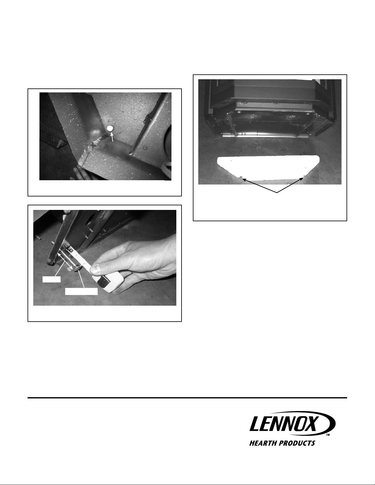
Step 2. Install your four leveling bolts (provided with the appliance). Open
the main front door and remove the two bolts in the front right
and front left of the bottom of the firebox (see Figure 3). Note:
Placing a level on the insert top is recommended to ensure your
insert is level. Again with the insert very cautiously tilted back,
insert your four leveling bolts approximately 2-1/16 inches into
the holes provided at the bottom of the insert see Figure 4.
Remove
Figure 3
Step 3. Set the insert on the insulation board. Now that the insert is
level, place your insulation board in place where the insert will be
installed and set the PI40 insert over the insulation board so the
two front leveling legs line up with the two cut-outs in the front
of the insulation board (see Figure 5). Your PI40 heat kit is now
installed.
Bottom of
Insert
Insulation Board
There are two cut-outs which provide
clearance for leveling legs.
Figure 5
2-1/16”
Leveling Bolt
Figure 4
NOTE: DIAGRAMS & ILLUSTRATIONS ARE NOT TO SCALE.
Lennox Hearth Products reserves the right to make changes at any time, without notice, in
design, materials, specifications, prices and also to discontinue colors, styles and products.
Consult your local distributor for fireplace code information.
Printed in U.S.A. © 2009 Lennox Hearth Products
P/N 506033-01 Rev. A 02/2009
1110 West Taft Avenue • Orange, CA 92865
 Loading...