

Lennox 2PGE13 series, 2, PGE15 series, 4PGE15 series, 4PGE13 series Installation Instructions Manual
...
INSTALLAT I STRUCTIO
Gas
(2,4)PG E/SG(13/15)
Heatin ectric Coolin
SAFETY ................................................. 2
INSTALLATION ....................................... 2
START-UP ............................................ 10
OPERATION ........................................ 11
MAINTENANCE ................................... 13
Series
Package Unit
TABLE OF CONTENTS
CONTROL SYSTEM DIAGNOSTICS .. 14
WIRING DIAGRAMS ............................ 15
Manufactured By
A.A.C.
A Lennox International Inc. Company
421 Monroe Street
Bellevue, OH 44811
6AS-HREB
II!il!iilIIIllUI!11II o
I A CAUTION1
The installation of the furnace, wiring, warm air ducts, venting, etc. must conform to the requirements of the
National Fire Protection Association; the National Fuel Gas Code, ANSI Z223.1 (latest edition) and the
National Electrical Code, ANSl/NFPA No. 70 (latest edition) in the United States; the Canadian Installation
Codes CAN/CGA-B149.1 & .2 (latest edition) and the Canadian Electrical Code Part 1, CSA 22.1 (latest
edition) in Canada; and any state or provincial laws, local ordinances, or local gas utility requirements. Local
authorities having jurisdiction should be consulted before installation is made. Such applicable regulations
or requirements take precedence over the general instructions in this manual.
# 48111B005 Save these instructionsfor future reference Page 1
SAFETY INSTALLATION
The following is a list of safety rules and precautions that
must be followed when installing this furnace.
1. Use only with the type of gas approved for this
furnace. Refer to the furnace rating plate.
2. Install this furnace only in a location and position as
specified in the Location section on page 3 of these
instructions.
3. Adequate clearance must be provided around the vent
hood as specified in the Clearances section on page 4
of these instructions.
4.
Never test for gas leaks with an open flame. Use a
commercially available soap solution made specifi-
cally for the detection of leaks to check all connec-
tions, as specified in Gas Supply and Piping
beginning on page 6 of these instructions.
Always install furnace to operate within the furnace's
intended temperature-rise range with a duct system
which has an external static pressure within the allowable
range, as specified in Temperature Rise on page 11 of
these instructions. See furnace rating plate.
These instructions must be hung on or near the
furnace in a conspicuous place.
These units are single package air conditioners with gas
heat designed for outdoor installation on a rooftop or a slab.
The units are completely assembled. All piping, refrigerant
charge, and electrical wiring are factory installed and
tested. The units require only electric power, gas piping,
condensate drain, and duct connections, plus assembly of
the heating vent hood at the point of installation.
If components are to be added to a unit to meet local
codes, they are to be installed at the dealer's and/or
customer's expense.
The size of unit for the proposed installation should be based
on heat loss/heat gain calculation made according to the
methods of Air Conditioning Contractors of America (ACCA).
These installation instructions are intended as a
general guide only, for use by an experienced, quali-
fied contractor.
These units are listed by UL:
6.
The furnace is not recommended for use for temporary
heating of buildings or structures under construction
unless certain installationand operating conditions are
adhered to, as specified in the Location section on
page 3 of these instructions.
• For use as a forced air furnace with cooling unit.
For outdoor installation only.
For installation on combustible material.
For use with natural gas or propane gas.
(Conversion kit required for propane gas application.)
These units are not suitable for use with conventional
venting systems.
IMPORTANT: This product has been designed and manu-
factured to meet ENERGY STAR criteria for energy effi-
ciency. However, proper refrigerant charge and proper air
flow are critical to achieve rated capacity and efficiency.
Installation of this product should follow the manufacturer's
refrigerant charging and airflow instructions. Failure to
confirm proper charge and airflow may reduce energy
efficiency and shorten equipment life.
inspection
As soon as the unit is received, it should be inspected for
possible damage during transit. Ifdamage is evident, the
extent of the damage should be noted on the carrier's
freight bill. A separate request for inspection by the
carrier's agent should be made in writing.
Page 2 # 48111 B005
Location • Air filters must be replaced upon construction completion.
Use the following guidelines to select a suitable location
for the unit.
1. Unit is designed for outdoor installation only. Unit must
be installed so all electrical components are protected
from water.
2. Condenser coils must have an unlimited supply of air.
3. For ground level installation, use a level prefabricated
pad or use a level concrete slab. Do not tie the slab to
the building foundation.
4. Maintain level within a tolerance of 1/4" maximum
across the entire length or width of the unit.
5. Do not locate the unit where the combustion air supply
will be exposed to any of the following substances:
Permanent wave solutions
Chlorinated waxes and cleaners
Chlorine-based swimming pool chemicals
Water softening chemicals
Deicing salts or chemicals
Carbon tetrachloride
Halogen-type refrigerants
Cleaning solvents (such as perchloroethylene)
Printing inks, paint removers, varnishes, etc.
Cements and glues
Antistatic fabric softeners for clothes dryers
Masonry acid washing materials
Chlorinated laundry products
Hydrochloric acid
The input rate and temperature rise must be set per
the unit rating plate.
100% outdoor air must be provided for combustion air
requirements during construction, installation of this unit
in its intended outdoor location will accomplish this.
The heat exchanger, components, duct system, air
filter(s), and evaporator coil must be thoroughly
cleaned following final construction cleanup.
Following the final cleaning, all furnace operating
conditions (including ignition, input rate, temperature
rise, and venting) must be verified according to these
instructions.
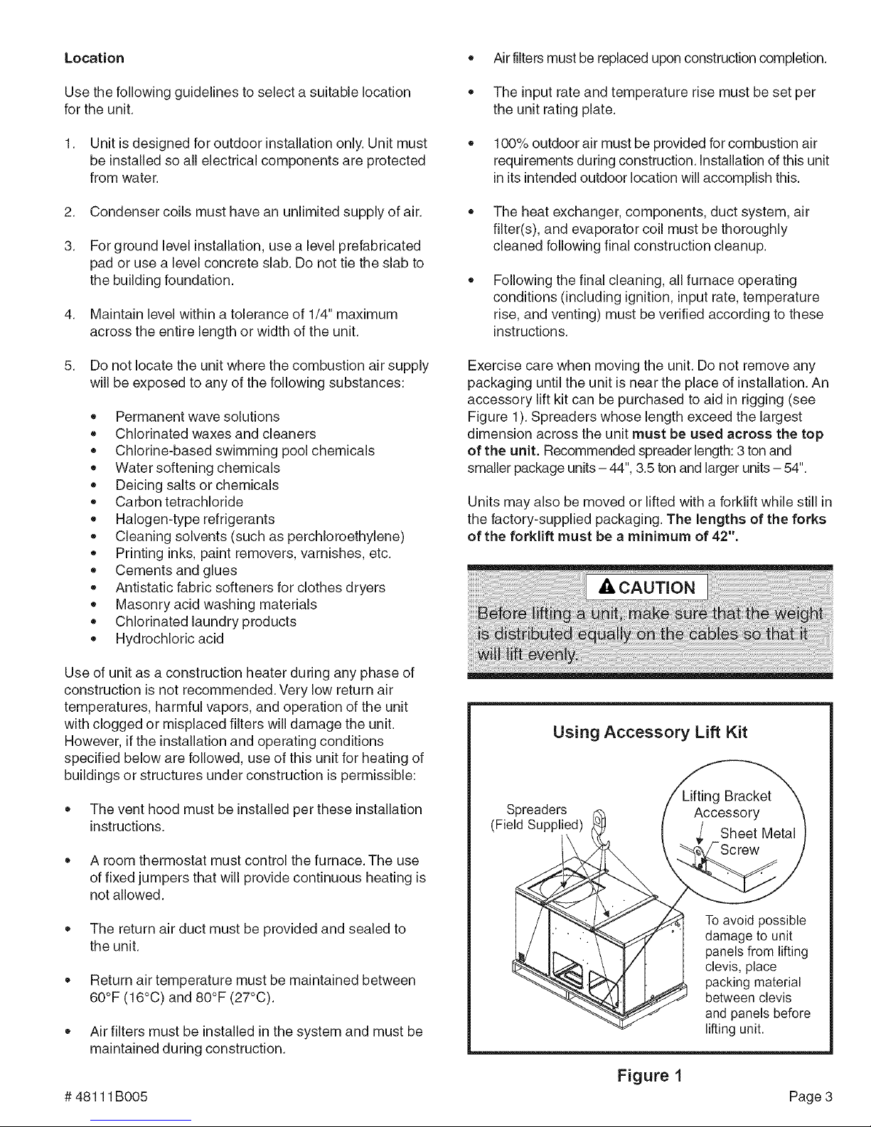
Exercise care when moving the unit. Do not remove any
packaging until the unit is near the place of installation. An
accessory lift kit can be purchased to aid in rigging (see
Figure 1). Spreaders whose length exceed the largest
dimension across the unit must be used across the top
of the unit. Recommended spreader length: 3 ton and
smaller package units- 44", 3.5 ton and larger units - 54".
Units may also be moved or lifted with a forklift while still in
the factory-supplied packaging. The lengths of the forks
of the forklift must be a minimum of 42".
Use of unit as a construction heater during any phase of
construction is not recommended. Very low return air
temperatures, harmful vapors, and operation of the unit
with clogged or misplaced filters will damage the unit.
However, if the installation and operating conditions
specified below are followed, use of this unit for heating of
buildings or structures under construction is permissible:
The vent hood must be installed per these installation
instructions.
A room thermostat must control the furnace. The use
of fixed jumpers that will provide continuous heating is
not allowed.
The return air duct must be provided and sealed to
the unit.
Return air temperature must be maintained between
60°F (16°0) and 80°F (27°0).
Air filters must be installed in the system and must be
maintained during construction.
# 48111 BOO5 Page 3
Using Accessory Lift Kit
Spreaders
(Field Supplied)
To avoid possible
damage to unit
panels from lifting
clevis, place
packing material
between clevis
and panels before
lifting unit.
Figure 1
Roof Curb Installation
If a roof curb is used, follow the manufacturer's installation
instructions and be sure that all required clearances are
observed (see following Clearances section).
Roof Curb Assembly
Figure 2
Clearances
All units require certain clearances for proper operation
and service. Refer to Table 1 for the minimum clearances
to combustibles as well as minimum clearances neces-
sary for servicing and proper unit operation.
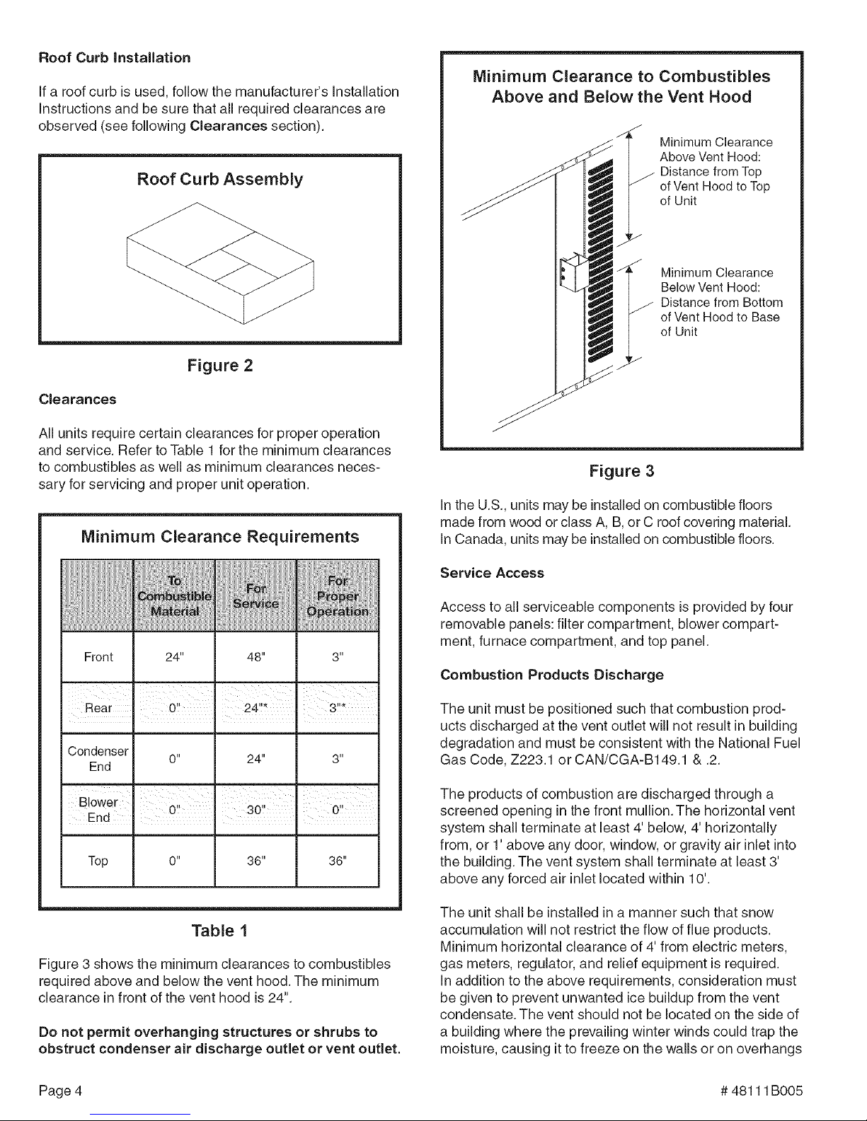
Minimum Clearance Requirements
Minimum Clearance to Combustibles
Above and Below the Vent Hood
Minimum Clearance
Above Vent Hood:
Distance from Top
of Vent Hood to Top
of Unit
Minimum Clearance
Below Vent Hood:
Distance from Bottom
of Vent Hood to Base
of Unit
Figure 3
In the U.S., units may be installed on combustible floors
made from wood or class A, B, or C roof covering material.
In Canada, units may be installed on combustible floors.
Front 24" 48" 3"
Rear 0!! 24!!* 3!!_
Condenser
End
Blower , '
End . . ,
Top 0" 36" 36"
0" 24" 3"
0!' 30" 0!!
n n
Table 1
Figure 3 shows the minimum clearances to combustibles
required above and below the vent hood. The minimum
clearance in front of the vent hood is 24".
Do not permit overhanging structures or shrubs to
obstruct condenser air discharge outlet or vent outlet.
Service Access
Access to all serviceable components is provided by four
removable panels: filter compartment, blower compart-
ment, furnace compartment, and top panel.
Combustion Products Discharge
The unit must be positioned such that combustion prod-
ucts discharged at the vent outlet will not result in building
degradation and must be consistent with the National Fuel
Gas Code, Z223.1 or CAN/CGA-B149.1 & .2.
The products of combustion are discharged through a
screened opening in the front mullion. The horizontal vent
system shall terminate at least 4' below, 4' horizontally
from, or 1' above any door, window, or gravity air inlet into
the building. The vent system shall terminate at least 3'
above any forced air inlet located within 10'.
The unit shall be installed in a manner such that snow
accumulation will not restrict the flow of flue products.
Minimum horizontal clearance of 4' from electric meters,
gas meters, regulator, and relief equipment is required.
In addition to the above requirements, consideration must
be given to prevent unwanted ice buildup from the vent
condensate. The vent should not be located on the side of
a building where the prevailing winter winds could trap the
moisture, causing it to freeze on the walls or on overhangs
Page 4 # 48111 B005
(undereaves).Theventlocationshouldnotdischarge
overasidewalk,patio,orotherwalkwaywherethecon-
densatecouldcausethesurfacetobecomeslippery.
kWARNING
The products of combustion must not be allowed to
accumulate within a confined space and recirculate.
Vent Hood
The unit is shipped with the vent hood, screen, and sheet
metal screws packed in the plastic bag containing the
Installation Instructions.
To attach the vent hood and screen to the unit:
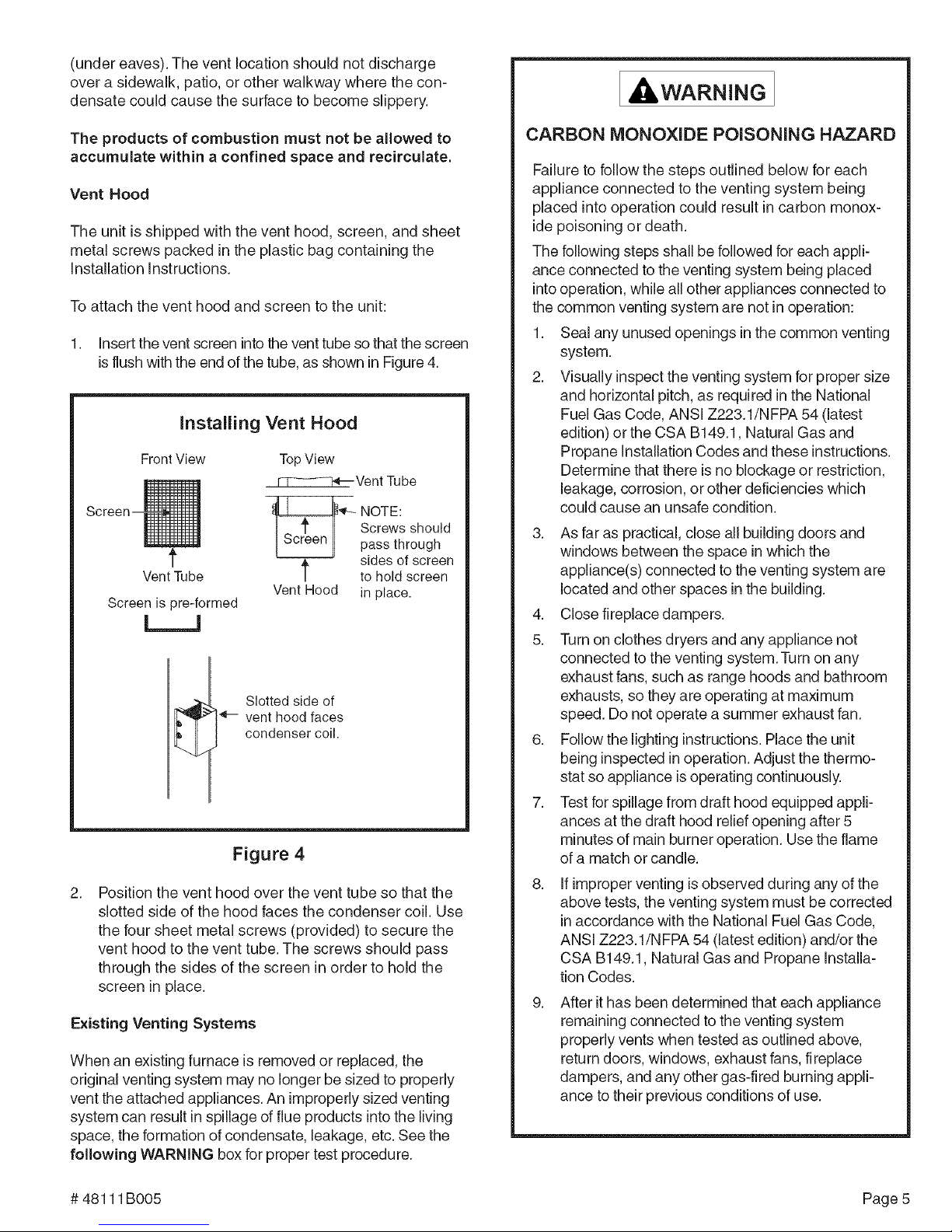
1. Insert the vent screen into the vent tube so that the screen
is flush with the end of the tube, as shown in Figure 4.
Installing Vent Hood
FrontView TopView
_Vent Tube
'_-- OTE:
Screws should
pass through
sides of screen
VentTube
Screen is lore-formed
t to hold screen
Vent Hood in place.
L__J
_-- vent hood faces
condenser coil.
Slotted side of
Figure 4
2. Position the vent hood over the vent tube so that the
slotted side of the hood faces the condenser coil. Use
the four sheet metal screws (provided) to secure the
vent hood to the vent tube. The screws should pass
through the sides of the screen in order to hold the
screen in place.
Existing Venting Systems
When an existing furnace is removed or replaced, the
original venting system may no longer be sized to properly
vent the attached appliances. An improperly sized venting
system can result in spillage of flue products into the living
space, the formation of condensate, leakage, etc. See the
following WARNING box for proper test procedure.
CARBON MONOXIDE POISONING HAZARD
Failure to follow the steps outlined below for each
appliance connected to the venting system being
placed into operation could result in carbon monox-
ide poisoning or death.
The following steps shall be followed for each appli-
ance connected to the venting system being placed
into operation, while all other appliances connected to
the common venting system are not in operation:
1. Seal any unused openings in the common venting
system.
2. Visually inspect the venting system for proper size
and horizontal pitch, as required in the National
Fuel Gas Code, ANSI Z223.1/NFPA 54 (latest
edition) orthe CSA B149.1, Natural Gas and
Propane Installation Codes and these instructions.
Determine that there is no blockage or restriction,
leakage, corrosion, or other deficiencies which
could cause an unsafe condition.
3. As far as practical, close all building doors and
windows between the space in which the
appliance(s) connected to the venting system are
located and other spaces inthe building.
4. Close fireplace dampers.
5. Turn on clothes dryers and any appliance not
connected to the venting system. Turn on any
exhaust fans, such as range hoods and bathroom
exhausts, so they are operating at maximum
speed. Do not operate a summer exhaust fan.
6. Follow the lighting instructions. Place the unit
being inspected in operation. Adjust the thermo-
stat so appliance is operating continuously.
7. Test for spillage from draft hood equipped appli-
ances at the draft hood relief opening after 5
minutes of main burner operation. Use the flame
of a match or candle.
8.
If improper venting is observed during any of the
above tests, the venting system must be corrected
in accordance with the National Fuel Gas Code,
ANSI Z223.1/N FPA 54 (latest edition) and/or the
CSA B149.1, Natural Gas and Propane installa-
tion Codes.
9.
After it has been determined that each appliance
remaining connected to the venting system
properly vents when tested as outlined above,
return doors, windows, exhaust fans, fireplace
dampers, and any other gas-fired burning appli-
ance to their previous conditions of use.
# 48111B005 Page 5
 Loading...