

Page 1
O24/OF24
Service Literature
Corp. 9804-L4
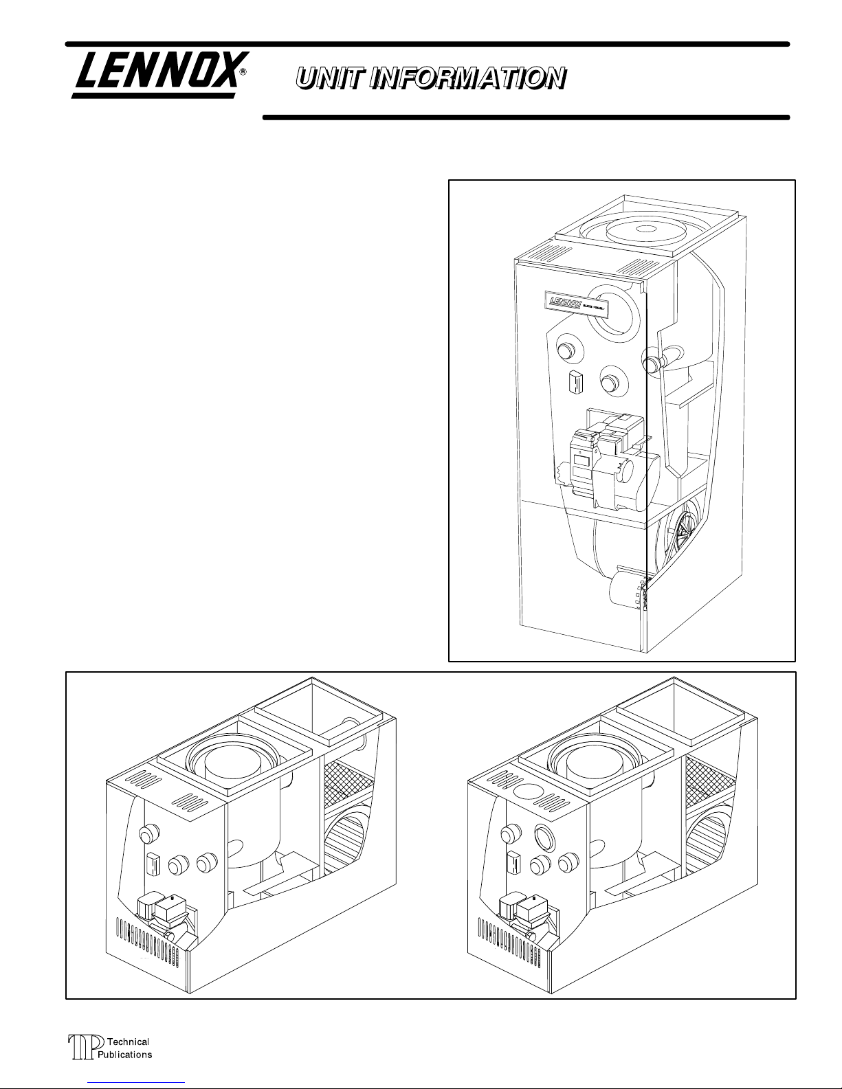
O24 / OF24 SERIES UNITS
O24 (Elite 80) series units are heating only mid-efficiency
upflow oil furnaces manufactured with Beckett oil burners.
O24 units are available in heating capacities of 70,000 to
154,000 Btuh (20.5 to 45.1 kW). O24 units are suitable for resi
dential or commercial applications.
OF24 (Elite 80) series units are heating only mid-efficiency loboy up-flow furnaces, which cime in front (OF24) or rear
(OF24R) flue openings. Both furnaces use Beckett oil burners
with heating capacities of 105,000 to 154,000 Btuh (30.8 kW to
45.1 kW). OF24 units are suitable for residential or commercial
application.
The drum type heat exchanger comes with strategically
placed ports allowing easy cleaning. The oil burner can be
easily removed for inspection and service. The mainte
nance section gives a detailed description on how this is
done.
Information contained in this manual is intended for use by
experienced HVAC service technicians only. All specifica
tions are subject to change. Procedures outlined in this
manual are presented as a recommendation only and do not
supersede or replace local or state codes.
OF24
REAR FLUE
MODEL
O24 UPFLOW
OF24
FRONT FLUE
MODEL
Page 1
1998 Lennox Industries Inc.
Litho U.S.A.
Page 2
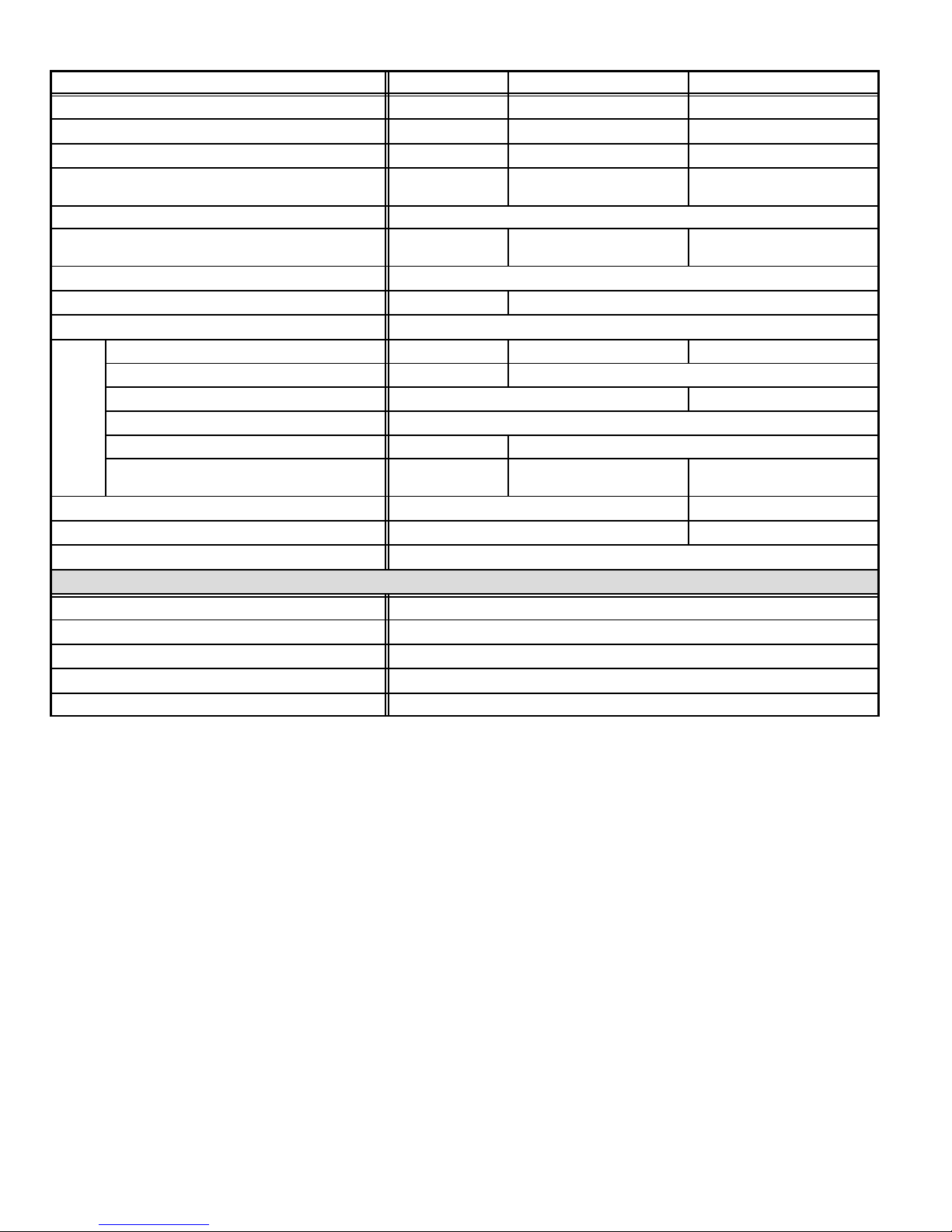
SPECIFICATIONS O24
Model Number O24-70 O24-105/120 O24-140/154
Input - Btuh (kW) low/high 70,000 (20.5) 105,000 / 120,000(30.8 / 35.2) 140,000 / 154,000(41.0 / 45.1)
Output - Btuh (kW) low/high 57,000 (16.7) 85,000 / 97,000 (24.9 / 28.4) 113,000 / 125,000 (33.1 / 36.6)
A.F.U.E. 82% 81% 82%
Nozzle Rating - gph (L/hr) and spray angle .50 (1.9) - 80° hollow
Flue Size Diameter - in. (mm) 6 (152)
Temperature Rise - F (C) 55 - 85 (30 - 47)
Oil Burner pump 1 Stage
Oil Burner pump pressure - psig (Pa) 100 (690) 140 (965)
Oil Burner air inlet connection (dia.) - in. (mm) 4 (102)
Motor hp (W) 1/6 (124) 1/4 (187) 3/4 (560)
Motor pulley - in. (mm) 3-1/4 (83) 4 (102)
Blower
Number and size of filters - in. (mm) (1) 16 x 25 x 1 (2) 16 x 25 x 1
Shipping weight - lbs. (kg) 1 package 225 (102) 275 (125)
Electrical characteristics 115 volts - 60 hertz - 1 phase
Two Stage Oil Pump 65A44
Oil Filter - 10 micron, no mounting bracket 91P89
Oil Filter - 10 micron, with mounting bracket 53P92
Replacement cartridge for above - 10 micron, 45 gph (170 L/h) 53P93
Filter restriction indicator gauge 53P90
Annual Fuel Utilization Efficiency based on U.S. DOE test procedures and FTC labeling regulations. Isolated combustion system rating for nonweatherized furnaces.
Nozzle must be field provided for field conversion to higher heating input.
Cleanable frame type filters. Furnished with unit in Side Filter Adaptor Kit for field installation external to the cabinet.
Requires return air from both sides of cabinet.
Blower wheel nominal diameter x width - in. (mm) 10 x 8 (254 x 203) 12 x 9 (305 x 229)
Blower pulley - in. (mm) 7 (178)
Data
Belt size - in. (mm) 40 (1016) 41 (1041)
cfm (L/s) at .20 in. wg. (50 Pa) external static
pressure
Optional Accessories (Must Be Ordered Extra)
820 (390) 1170 (550) 1550 (730)
.65 (2.5) - 80°(-105 input) solid
.75 (2.8) - 80° (-120 input) solid
55 - 85 (30 - 47)(-105)
60 - 90 (33 - 50)(-120)
.85 (3.2) - 80° (-140 input) solid
1.00 (3.8) - 80° (-154 input) solid
50 - 80 (28 - 45)(-140)
60 - 90 (33 - 50)(-154)
Page 2
Page 3
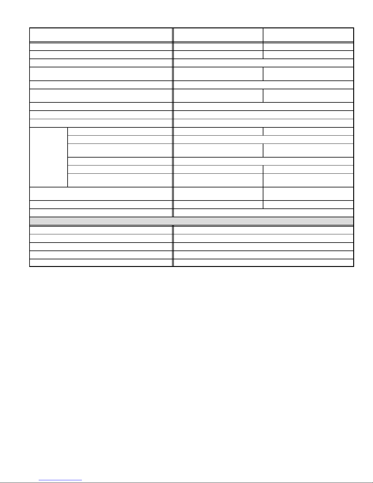
SPECIFICATIONS OF24(R)
Blower
Model Number
Input - Btuh (kW) low/high 105,000 / 120,000 (30.8 / 35.2) 140,000 / 154,000 (41.0 / 45.1)
Output - Btuh (kW) low/high 85,000 / 97,000 (24.9 / 28.4) 113,000 / 125,000 (33.1 / 36.6)
A.F.U.E. (low/high) 81%
Nozzle Rating - gph (L/hr) and spray angle
Flue Size Diameter - in. (mm) 6 (152)
Temperature Rise - F (C)
Oil Burner Pump 1 Stage
Oil Burner Pump Pressure - psig (Pa) 140 (965)
Oil Burner air inlet connection (dia.) - in. (mm) 4 (102)
Motor hp (W) 1/4 (187) 3/4 (560)
Motor pulley - in. (mm) 4 (102)
Blower wheel nominal diameter
Blower
Data
Number and size of filters in. (mm)
Shipping weight- - lbs. (kg) 1 package 255 (116) 290 (132)
Electrical Characteristics 115 volts - 60 hertz - 1 phase
Two Stage Oil Pump 65A44
Oil Filter - 10 micron, no mounting bracket 91P89
Oil Filter - 10 micron, with mounting bracket 53P92
Replacement cartridge for above - 10 micron, 45 gph (170 L/h) 53P93
Filter restriction indicator gauge 53P90
Annual Fuel Utilization Efficiency based on U.S. DOE test procedures and FTC labeling regulations. Isolated combustion system rating for non-weatherized furnaces.
Nozzle must be field provided for field conversion to higher heating input.
x width - in. (mm)
Blower pulley - in. (mm) 7 (178)
Belt size - in. (mm) 41 (1041) 42 (1067)
cfm (L/s) at .20 in. wg. (50 Pa) external static
pressure
Optional Accessories (Must Be Ordered Extra)
OF24-105/120
OF24-105/120R
.65 (2.5) - 80° (-105 input)
.75 (2.8) - 80° (-120 input)
45 - 75 (25 - 42) (-105 input)
55 - 85 (31 - 47) (-120 input)
10 x 8 (254 x 203) 12 x 9 (305 x 229)
1300 (615) (-105 input)
1220 (575) (-120 input)
(1) 18 x 19 x 1
(457 x 483 x 25)
OF24-140/154
OF24-140/154R
.85 (3.2) - 80° (-140 input)
1.00 (3.8) - 80° (-154 input)
50 - 80 (28 - 45) (-140 input)
55-85 (31 - 47) (-154 input)
1750 (825) (-140 input)
1700 (800) (-154 input)
(1) 19 x 21 x 1
( 483 x 533 x 25)
Page 3
Page 4
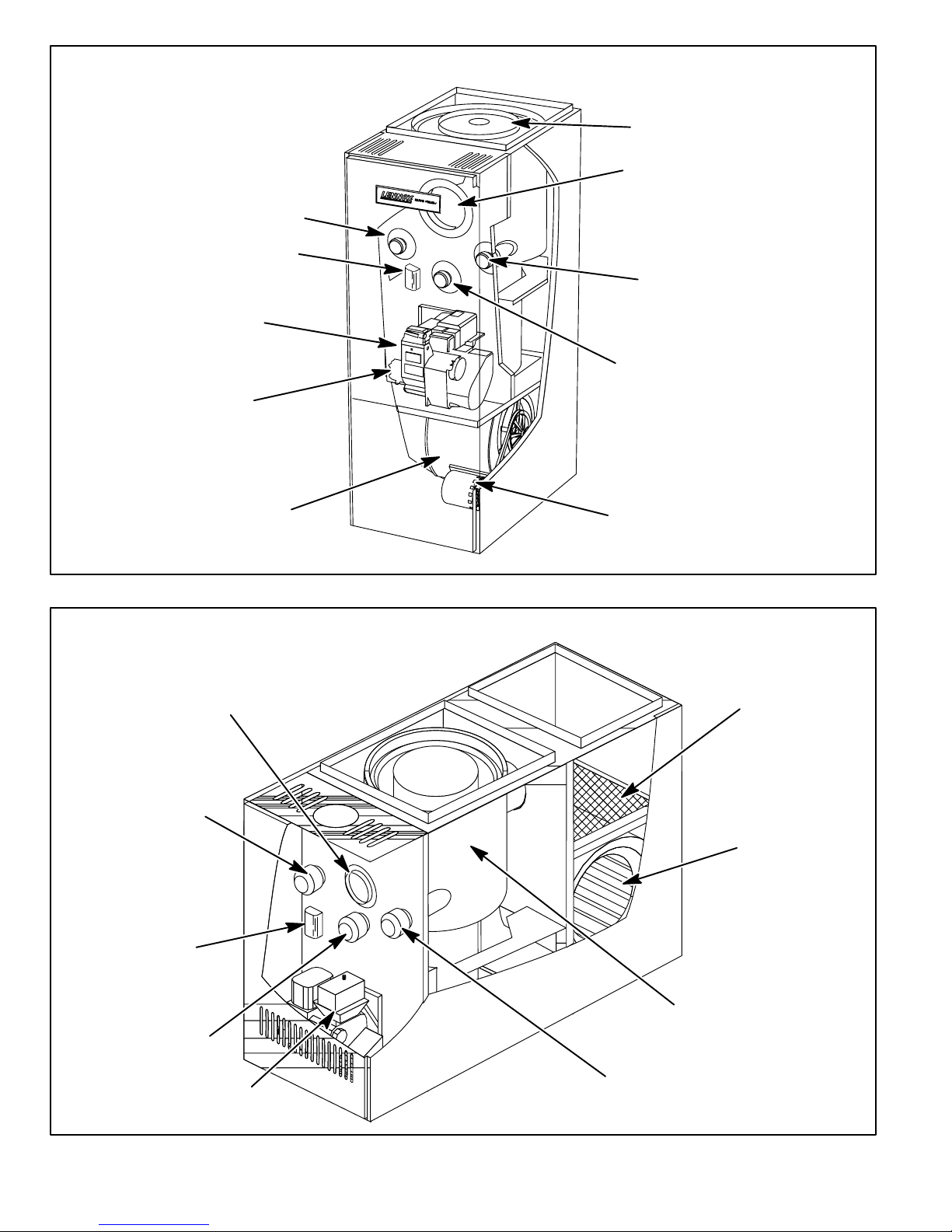
CLEAN-OUT PORT
LIMIT SWITCH
BECKETT
AFII BURNER
COMBUSTION AIR INTAKE
INDOOR BLOWER
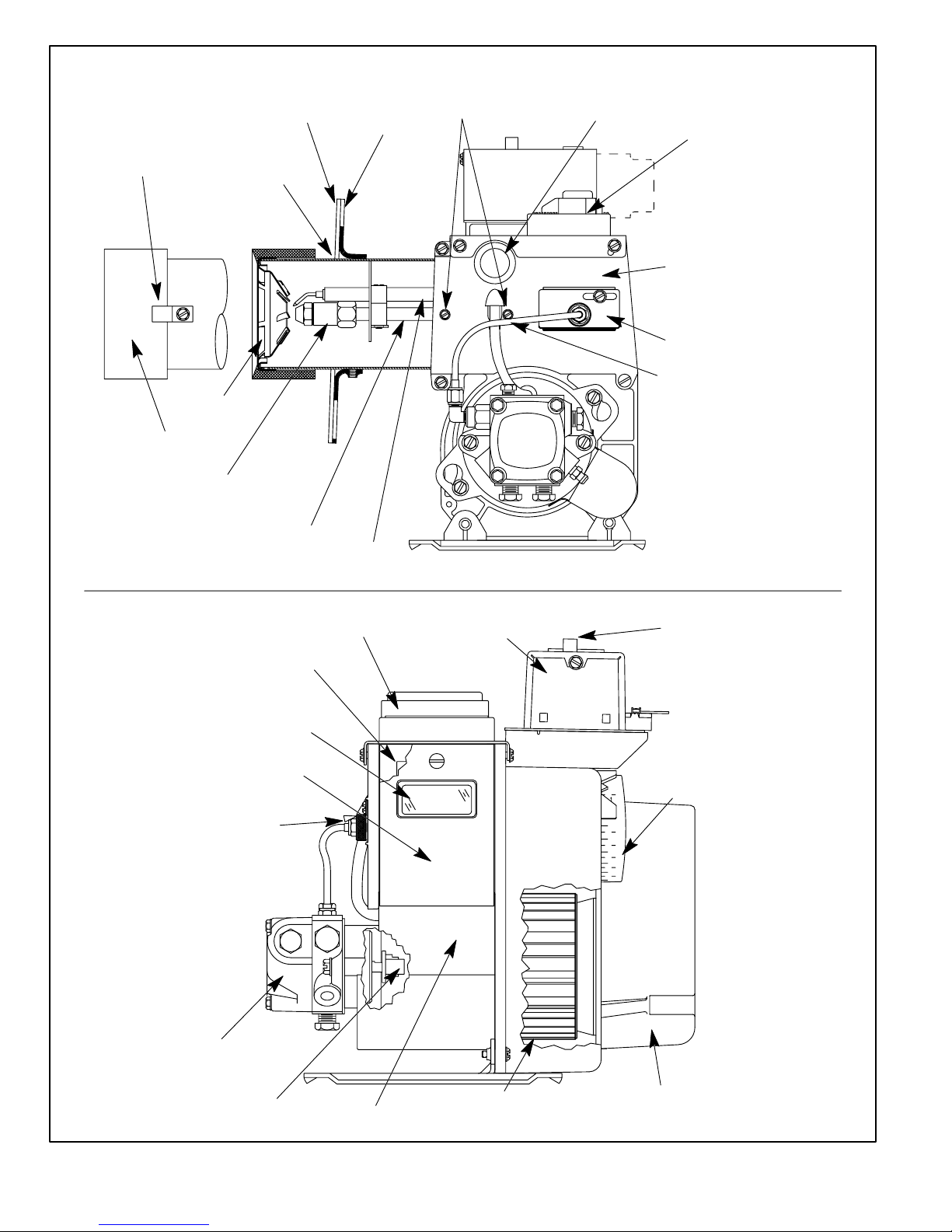
O24 GENERAL PARTS ORIENTATION
HEAT EXCHANGER
FLUE OPENING
CLEAN-OUT PORT
OBSERVATION PORT
BLOWER MOTOR
FLUE OPENING
CLEAN-OUT PORT
FAN LIMIT SWITCH
OBSERVATION PORT
FIGURE 1
OF24 GENERAL PARTS ORIENTA
TION
FILTER
INDOOR BLOWER
HEAT EXCHANGER
BECKETT
AFII BURNER
CLEAN-OUT PORT
FIGURE 2
Page 4
Page 5

Unit
Lennox Burner
Part Number
TABLE 1
FURNACE / BURNER SPECIFICATIONS
Burner
Model
*Initial Air
Dial
Setting
Output
Nozzle Size
(Delevan)
Pump
Pressure
Head
70 35K74 AFII 85 3.0
105 35K75 AFII 85 4.0
120 35K75 AFII 85 4.5
140 35K76 AFII 150 6.0
154 35K76 AFII 150 6.5
*NOTE: The initial air dial setting is provided to get unit started. The air dial setting MUST be adjusted after startup to
achieve proper combustion.
ELECTROSTATIC DISCHARGE (ESD)
Precautions and Procedures
CAUTION
Electrostatic discharge can affect electronic
components. Take precautions during furnace
installation and service to protect the furnace's
electronic controls. Precautions will help to avoid
control exposure to electrostatic discharge by
putting the furnace, the control and the techni
cian at the same electrostatic potential. Neutral
ize electrostatic charge by touching hand and all
tools on an unpainted unit surface, such as the
gas valve or blower deck, before performing any
service procedure.
57,000 BTU
(16.7 kW)
84,000 BTU
(24.6 kW)
105,000 BTU
(30.8 kW)
112,000 BTU
(32.8 kW)
125,000 BTU
(36.6 kW)
motor shaft also connects to the direct drive oil pump
through a coupler. The burner motor turns both the com
bustion air blower and the oil pump. The motor operates
at 3500 RPM.
Burner motors are overload protected. In the event of ex
cess motor temperature or current, the overload opens
to de-energize the motor. The overload automatically re
sets after temperature has returned to normal. Keep mo
tor clean to prevent starting switch from sticking. All AFII
motors are permanently lubricated. No further oiling is required.
0.50 X 80A
0.65 X 80B
0.75 X 80B
0.85 X 80B
1.00 X 80B
2-Combustion Air Blower / Pump Fuse (F22)
(-140 and -154 CSA units only)
In the -140 and -154 Canadian units an in line fuse (F22) is
used between the line voltage from the blower control and
the blower / pump motor. The fuse is rated at 300 volts and
15 amps.
100 psig
(689.5 kPa)
140 psig
965.3 kPa)
140 psig
965.3 kPa)
140 psig
965.3 kPa)
140 psig
965.3 kPa)
FB0
FB3
FB3
FB6
FB6
3- Pump
The O24 and OF24 oil furnaces use a single stage, 3450
RPM pump. A two stage pump is available as an option
(catalog # 65A44). The oil burner is shipped from factory
I-UNIT COMPONENTS
General parts orientation for the O24 and OF24 are shown in
figures 1 and 2 respectively. The O24 and OF24 burner, limit
switch and cleanout ports may be accessed by removing the
front access panel. The blower can be accessed in the O24
and OF24 by removing the blower access panel.
A-Burner (Figure 3)
The O24 and OF24 oil furnaces use the Beckett AFII burner.
The oil burner provides an atomized oil vapor mixed with the
correct proportion of air when it is ignited in the combustion
chamber. Oil burner minimum and maximum ratings are listed
on the unit nameplate. Proper air adjustment for these ratings
is achieved through the air adjustment dial. Set air dial to the
initial air dial setting (see table 1). After start up adjust air dial to
achieve proper combustion. Remember to tighten set screw on
air dial.
The AFII burner is available in five sizes with either a single
or two stage pump. Table 1 identifies the burners used in
Lennox units. Figure 3 shows the typical layout of the burner
assembly.
1-Combustion Air Blower / Pump Motor (B6)
The burner is activated by the primary control. A com
bustion air blower is mounted on the motor shaft. The
for use in a single line system. To convert the pump to a
two line system, install the bypass plug provided in the at
tached bag according to the accompanying instructions.
4-Burner Control (A3) & Transformer (T1)
The burner control, along with the matching cad cell, proves
flame and controls the burner. After the cad cell closes a circuit
to the burner control, the burner control de-energizes the safety
switch heater to allow the unit to operate normally. The burner
control allows 45 seconds for the cad cell to close. If the cad cell
remains open after the 45 second time frame, the burner con
trol locks out. The burner control must be manually reset by de
pressing the red reset button on top of the burner control.
Transformer (T1) is part of the burner control. T1 provides
24VAC to the low voltage components in the unit and to the
thermostat.
5-Cad Cell (R26)
Together the cad cell and the burner control prove flame.
The cad cell senses the presence of burner light (less re
sistance) to close a circuit to the burner control.
IMPORTANT-Burner should not be installed so it is ex
posed to direct sunlight or electric bulb light. If the cell
is exposed to light on start up, the burner will not oper
ate.
Page 5
Page 6
RETAINING
CLIP
HEAD
INSULATOR
O24 / OF24 OIL BURNER PARTS ARRANGEMENT
AIR TUBE
SCREWS
HOLE PLUG
CONNECTOR
AIR TUBE
ASSY FOR
FB HEADS
FB-HEAD
NOZZLE
ADAPTER
NOZZLE LINE
ELECTRODE HEAD
FLANGE
GASKET
ASSY.
FLANGE
ELECTRODE
ASSY
ELECTRONIC IGNITION
TRANSFORMER
MAIN
HOUSING
ASSY
ESCUTCHEON
PLATE
TUBE
REAR ACCESS
DOOR GASKET
VIEW PORT
REAR ACCESS
DOOR ASSY
SPLINED
OIL PUMP
ELECTRONIC IGNITION
TRANSFORMER
NUT
BURNER
CONTROL
RESET
BUTTON
AIR
ADJUSTMENT DIAL
0
3
4
5
6
7
8
COUPLING
COMBUSTION AIR
MOTOR
BLOWER
FIGURE 3
Page 6
WHEEL
INLET
AIR SCOOP
Page 7
6-Electronic Ignitor (A73)
The electronic ignitor provides the needed hot spark at the
electrodes to ignite the fuel mixture. The ignitor is a solid state
transformer which has 115V primary and 14,000V secondary
windings. The center of the secondary winding is grounded.
Each secondary terminal is 7000V to ground and the total volt
age between the electrodes is 14,000V.
NOTE-The leads for the solid state transformer are re
placeable and are available in a kit form.
NOTE-When testing the solid state transformer, do not
use a transformer tester designed for iron magnet trans
formers. Damage to the tester may result.
7-Gun Assembly
The gun assembly receives oil from the oil pump and feeds
it to the nozzle. The nozzle converts liquid oil into a fog-like
mist that is discharged through the flame retention head
into the combustion chamber.
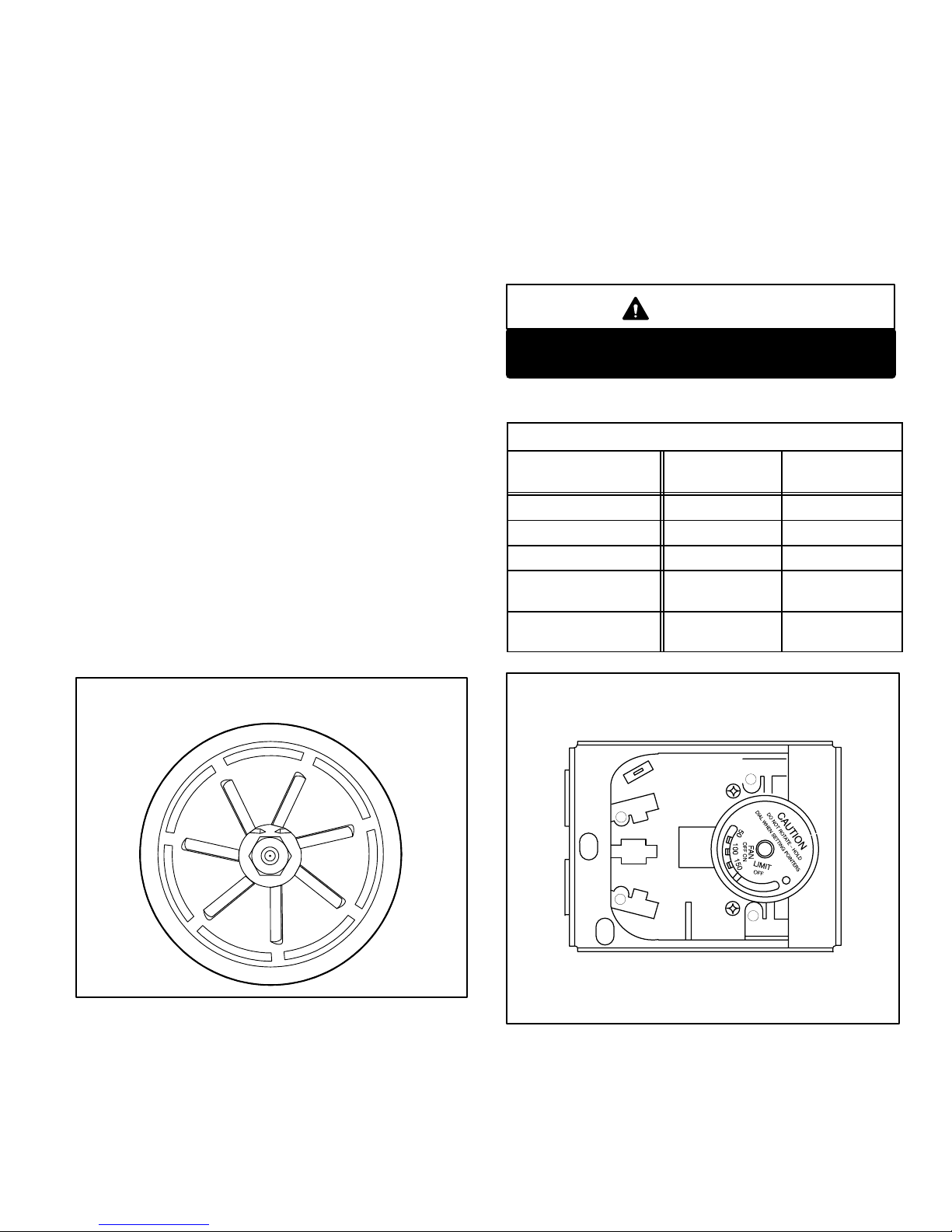
8-Flame Retention Heads
The stainless steel flame retention head (see figure 4) is
used to swirl (cone) the foglike oil and air mixture as it
enters the combustion chamber. Three different heads
are used in the O24/OF24. The firing rate dictates which
head is used. See table 1. The greater the FB number the
larger the slots on the head. When combustion takes
place, the flame will be cylindrical compact shaped as a
result.
B-Primary Fan/Limit Control (S10)
The primary limit on all O24and OF24 units, is located on
the vestibule panel (see figures 1 and 2 for location and fig
ure 5 for type). When excess heat is sensed in the heat ex
changer, the limit will open. If the limit is tripped, the blower
control deenergizes the thermostat, in turn shutting
down the un i t . The lim i t automatically resets when unit tem
p
erature returns to normal. See table 2 for limit set-points. The
fan control is factory set and is temperature acuated to con
trol blower operation. The fan control is set at 125F (52C )
on /100F (38C) off.
CAUTION
This furnace must not operate with a FAN ON
temperature greater than 130 degrees.
TABLE 2
PRIMARY LIMIT CONTROL (S10)
UNIT
O24-70 210F (99C) 180F (82C)
O24-105/120 220F (104C) 190F (88C)
O24-140/154 210F (99C) 180F (82C)
OF24-105/120
OF24-105/120R
OF24-140/154
OF24-140/154R
ACTUATES
ON TEMP. RISE
240F (116C) 210F (99C)
210F (99C) 180F (82C)
ACTUATES
ON TEMP. FALL
FLAME RETENTION HEAD
FB3 SHOWN
FIGURE 4
LIMIT CONTROL (S10)
S10
FIGURE 5
Page 7
Page 8

TABLE 3
BLOWER MOTOR AND CAPACITOR RATINGS
Unit
O24-70 35K59
O24-105/120 35K59
O24-140/154 35K62
OF24-105/120
OF24-105/120R
OF24-140/154
OF24-140/154R
Blower Motor
Part Number
35K59
35K62
Power Volts Hz Phase
1/3 HP
(248.6 KW)
1/3 HP
(248.6 KW)
3/4 HP
(559.5 KW)
1/3 HP
(248.6 KW)
3/4 HP
(559.5 KW)
C-Blower Compartment
Blower motor (B3) and capacitor (C4), are located in the
blower compartment. The blower compartment can be ac
cessed by removing the blower access panel.
1-Blower Motor (B3) and Capacitor (C4)
All O24 and OF24 series units use single phase belt drive
blower motors. All motors used are 115V permanent split ca
pacitor motors to ensure maximum efficiency. See table 3
for horsepower and capacitor ratings.
D-Optional Accessories
Optional accessories are available from Lennox for the O24
and OF24 series units. Some accessories are in kit form which
come with instructions.
1- Continues Low Speed Blower On - Off
Switch (S68)
The low speed on off switch is a kit (catalog # 67H91) which
permits continuous low speed blower operation. The switch is
a DPDT toggle switch.
2-Economizer Relay (K43)
The economizer relay (catalog # 65G40) is used to energize
the economizer if used. The relay is a 120V coil, single pole
contact.
Capacitor
Part Number
115 60 1 35K57 7.5 370
115 60 1 35K57 7.5 370
115 60 1 35K58 12.5 370
115 60 1 35K57 7.5 370
115 60 1 35K58 12.5 370
An oil filter is required for all models. Use an oil filter of gener
ous capacity for all installations. Install filter inside the building
between the tank shut-off valve and the burner. Locate filter
close to burner for easy servicing. The GAR-Ber 11BV-R or
equivalent filter (with the below specifications) is recom
mended.
Maximum Firing Rate: 10GPH (38LPH)
Micron Removal: 10
Filtering Area: 500 in.
Working Pressure: 15 PSI (103.4 kPa)
Inlet/Outlet Dimension: 3/8" (9.5 mm) NPT
Flow Rate: 45GPH (171LPH)
Care must be taken to ensure the restriction of the piping sys
tem, plus any lift involved, does not exceed the capabili
ty of the oil pump. Each installation will be different. Use
the following guide lines when determining to use a single or
two stage pump.
When using a single pipe system with the fuel supply level
with or above the burner (see figure 6) and a vacuum of 6" (152
mm) Hg or below, a single stage fuel unit with a supply line and
no return line should be adequate. Manual bleeding of the fuel
unit is required on initial start up. Failure to bleed air from the
pump could result in an air lock/oil starvation condition.
NOTE-As an extra precaution, cycle heating on and off
ten times after bleeding air from the pump. This will elimi
nate air in the gun assembly.
2
(3225.8 cm2)
MFD Volts
II-PLACEMENT AND INSTALLATION
Make sure unit is installed in accordance with installation in
structions and applicable codes.
A-Piping
The piping system and it's components (oil filter, safety valves,
shutoff valves, etc.) must be designed to provide clean, air free
fuel to the burner.
When using a two pipe system with the fuel supply level
below the level of the burner (see figure 7) a single stage
fuel unit should be used in lift conditions of up to 10 feet
(3 m) and/or a vacuum of 10" (254 mm) Hg or below. A
two stage fuel unit should be used when lift exceeds 10
feet (3 m) and/or a vacuum of 10" (254 mm) Hg to 15" (381
mm) Hg. Both conditions require the use of a return line that
purges the fuel unit of air by returning it to the fuel tank. Use
table 4 when determining the run and lift for piping.
Page 8
Page 9
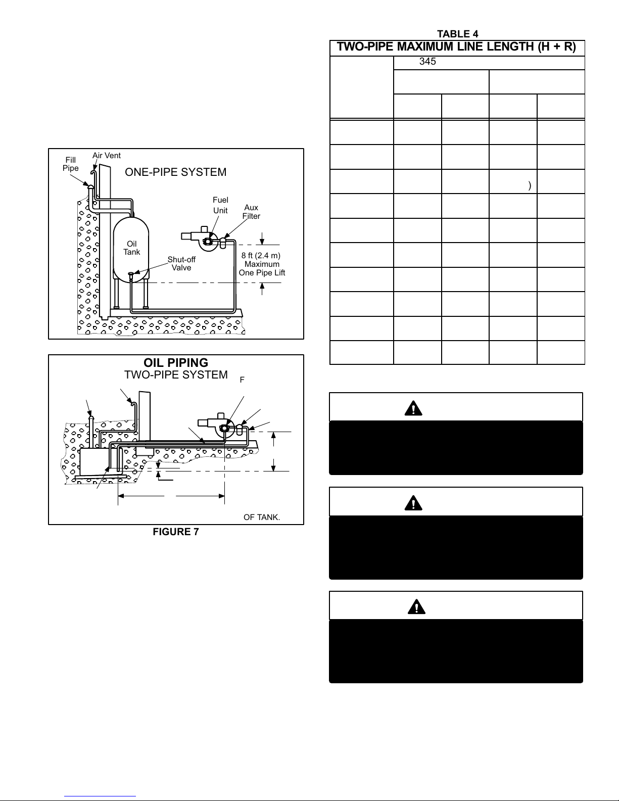
Before converting a onepipe system to a twopipe sys
g
tem the pump must be converted to a twopipe system.
To convert the pump, install the bypass plug according to
the instructions. Notice in the twopipe system the return
line must terminate 3" (76 mm) to 4" (102 mm) above the
supply inlet. Failure to do this may introduce air into the
system and could result in loss of prime.
NOTE-If using an outside tank in cold climates a number one
fuel or an oil treatment is strongly recommended.
Fill
Pipe
Air Vent
OIL PIPING
ONEPIPE SYSTEM
Fuel
Unit
Oil
Tank
Shut-off
Valve
Aux
Filter
8 ft (2.4 m)
Maximum
One Pipe Lift
FIGURE 6
OIL PIPING
TWOPIPE SYSTEM
Air Vent
Fill
Pipe
Return
Line
Oil
Tank
3"-4"
(76mm -102mm)
Return
Line
OUTSIDE TANK FUEL UNIT ABOVE BOTTOM OF TANK.
R
FIGURE 7
Fuel
Unit
Aux
Filter
Inlet
H
TABLE 4
TWO-PIPE MAXIMUM LINE LENGTH (H + R)
3450 RPM - 3 GPH (11.4 LPH)
Lift H"
Figure 6
0'
(0.0 m)
2'
(0.6 m)
4'
(1.2m)
6'
(1.8m)
8'
(2.4m)
10'
(3.0m)
12'
(3.7m)
14'
(4.3m)
16'
(4.9m)
18'
(5.5m)
3/8" (10 mm) OD
Tubing
Single
Stage
84'
(25.6 m)
73'
(22.3 m)
63'
(19.2 m)
52'
(15.8 m)
42'
(12.8 m)
31'
(9.4 m)
21'
(6.4 m)
---
---
Two
Stage
93'
(28.3 m)
85'
(25.9 m)
77'
(23.5 m)
69'
(21.0 m)
60'
(18.3 m)
52'
(15.9 m)
44'
(13.4 m)
36'
(11.0 m)
27'
(8.2 m)
--- --- ---
1/2" (12 mm) OD
Tubing
Single
Stage
100'
(30.5 m)
100'
(30.5 m)
100'
(30.5 m)
100'
(30.5 m)
100'
(30.5 m)
100'
(30.5 m)
83'
(25.3 m)
41'
(12.5 m)
---
Two
Stage
100'
(30.5 m)
100'
(30.5 m)
100'
(30.5 m)
100'
(30.5 m)
100'
(30.5 m)
100'
(30.5 m)
100'
(30.5 m)
100'
(30.5 m)
100'
(30.5 m)
(23.2 m)
B-Venting Considerations
WARNING
Combustion air openings in front of the furnace
must be kept free of obstructions. Any obstruction
will cause improper burner operation and may re
sult in a fire hazard or injury.
WARNING
The barometric shall be in the same atmospheric
pressure zone as the combustion air inlet to the
furnace. Deviation from this practice will cause im
proper burner operation and may result in a fire
hazard or injury.
76'
CAUTION
Do not store combustible materials near the fur
nace or supply air ducts. The material (such as
paint, motor oil, gasoline, paint thinner, etc.) may
ignite by spontaneous combustion creating a fire
hazard.
Page 9
Page 10

WARNING
This furnace is certified for use with type L" vent.
B" vent must not be used with oil furnaces.
11- The furnace shall be connected to a factory built
chimney or vent complying with a recognized stan
dard, or masonry or concrete chimney lined with a
lining material acceptable to the authority having ju
risdiction.
NOTE-Oil burning equipment may be vented into an ap
proved masonry chimney or type L vent. (Type L vent is sim
ilar in construction to type B gas vent except it carries a
higher temperature rating and is constructed with an inner
liner of stainless steel rather than aluminum).
Prior to installation of unit, make a thorough inspection of the
chimney to determine whether repairs are necessary. Make
sure the chimney is properly constructed and sized accord
ing to the requirements of the National Fire Protection Asso
ciation. The smallest dimensions of the chimney should be at
least equal to the diameter of the furnace vent connector.
Make sure the chimney will produce a steady draft sufficient
to remove all the products of combustion from the furnace. A
draft of at least .04" w.c. (9.9 Pa) is required during burner
operation.
1 - Local building codes may have more stringent installa
tion requirements and should be consulted before
installation of unit.
2 - The vent connector should be as short as possible to
do the job.
COMBUSTIBLE
WALL
BAROMETRIC
CONTROL*
(IN EITHER
LOCATION)
WALL THIMBLE
THIMBLE
VENT PIPE
FIGURE 8
MASONRY CHIMNEY
LINER
3 - The vent connector should not be smaller than the out
let diameter of the vent outlet of the furnace.
4 - Pipe should be at least 24 gauge galvanized.
5 - Single wall vent pipe should not run outside or through
any unconditioned space.
6 - Chimney should extend 3 feet (0.9 m) above the highest
point where the vent passes through the roof, and 2 feet
(0.6 m) higher than any portion of a building within a hor
izontal distance of 10 feet (3 m).
7 - The vent must not pass through a floor or ceiling. Clear
ances to single wall vent pipe should be no less than 6"
(152 mm); more if local codes require it.
8 - The vent may pass through a wall where provisions have
been made for a thimble as specified in the Standards of
the National Board of Fire Underwriters. See figure 8.
9 - The vent pipe should slope upward toward the chimney
on horizontal run at least 1/4 inch (6 mm) to the foot
(0.3 m) and should be supported by something other
than the furnace, such as isolation hangers. See figure 9.
10- Extend the vent pipe into the chimney so that it is flush
with the inside of the vent liner. Seal the joint between
the pipe and the liner.
CLEANOUT
MASONRY
CHIMNEY
CLEANOUT
*Barometric control may be installed in either vertical or horizontal
section of vent pipe within 18" (457 mm) of vent outlet of furnace.
FIGURE 9
12- When two or more appliances vent into a common vent,
the area of the common vent should not be less than the
area of the largest vent or vent connection plus 50% of the
areas of the additional vent or vent connection. Chimney
must be able to sufficiently vent all appliances operating at
the same time.
13- The vent pipe shall not be connected to a chimney vent
serving a solid fuel appliance or any mechanical draft sys
tem.
14- All unused chimney openings should be closed.
15- All vent pipe run through unconditioned areas or outside
shall be constructed of factory built chimney sections.
See figure 10.
Page 10
Page 11

16- Where condensation of vent gas is apparent, the vent
should be repaired or replaced. Accumulation of con
densation in the vent is unacceptable.
FACTORY-BUILT CHIMNEY
BAROMETRIC
CONTROL*
(IN EITHER
LOCATION)
*Barometric control may be installed in either vertical or horizontal
section of vent pipe within 18" (457 mm) of vent outlet of furnace.
FACTORY
BUILT
CHIMNEY
FIGURE 10
17- Vent connectors serving this appliance shall not be
connected into any portion of mechanical draft sys
tems operating under positive pressure.
18- Keep the area around the vent terminal free of snow,
ice and debris.
NOTE-If vent pipe needs to exit from side of cabinet, use the
cross hairs (located on either side of the unit) to cut a 6" (152
mm) round hole. Attach finishing plate (provided) with four
sheet metal screws to cover rough edges.
Combustion and Ventilation Air
(Confined and Unconfined Spaces)
Until recently, there was no problem in bringing in suffi
cient amounts of outdoor air for combustion -- infiltration
provided all the air that was needed and then some. In
today's homes built with energy conservation in mind,
tight construction practices make it necessary to bring in
air from outside for combustion. Consideration must also be
given to the use of exhaust fans, appliance vents, chimneys
and fireplaces because they force additional air that could
be used for combustion out of the house. Unless outside
air is brought into the home for combustion, negative
pressure (pressure outside is greater than inside pres
sure) will build to the point that a down draft can occur in
the furnace vent pipe or chimney. Combustion g a ses enter
the living space creating a potentially dangerous situa
tion.
The importance of the previous paragraph cannot be
overstated. Users may inadvertently block fresh air in
takes after installation.
In the absence of local codes concerning air for combus
tion and ventilation, the following section outlines guide
lines and recommends procedures for operating oil fur
naces in a manner that ensures efficient and safe
operation. Special consideration must be given to combus
tion air needs as well as requirements for exhaust vents and oil
piping.
Combustion Air Requirements
CAUTION
Insufficient combustion air can cause headaches,
nausea, dizziness or asphyxiation. It will also
cause excess water in the heat exchanger result
ing in rusting and premature heat exchanger fail
ure. It can also cause property damage.
All oil-fired appliances require air to be used for the combus
tion process. If sufficient amounts of combustion air are not
available, the furnace or other appliance will operate in an inef
ficient and unsafe manner. Enough air must be provided to
meet the needs of all fuel-burning appliances, as well as ap
pliances such as exhaust fans which force air out of the home.
When fireplaces, exhaust fans, or clothes dryers are used at
the same time as the fur n a ce, much mo re air is required to
ensure proper combustion and to prevent a down-draft
situation. Insufficient amounts of air also cause incom
plete combustion which can result in sooting. Requirements
for providing air for combustion and ventilation depend largel y
on whether the furnace is installed in an unconfined or
confined space.
Unconfined Space
An unconfined space is an area such as a basement or
large equipment room with a volume greater than 50 cu
bic feet (1.4 cubic meters) per 1,000 Btu (293 W) per
hour of the combined input rating of all appliances
installed in that space. This space also includes adjacent
rooms which are not separated by a door. Though an area may
appear to be unconfined, it might be necessary to bring in out
door air for combustion if the structure does n o t pr o v ide
enough air by infiltration. If the furnace is located in a
building of tight construction with weather stripping and
caulking around the windows and doors, follow the proce
dures outlined for using air from the outside for combus
tion and ventilation.
Confined Space
A confined space is an area with volume less than 50 cu
bic feet (1.4 cubic meters) per 1,000 Btu (293 W) per
hour of the combined input rating of all appliances
installed in that space. This definition includes furnace closets
or small equipment rooms.
When the furnace is installed so that supply ducts carry air
circulated by the furnace to areas outside the space con
taining the furnace, the return air must be handled by ducts
which are sealed to the furnace casing and which terminate
Page 11
Page 12

outside the space containing the furnace. This is especially im
portant when the furnace is mounted on a platform in a con
fined space such as a closet or small equipment room. Even a
small leak around the base of the unit at the platform or at the
return air duct connection can cause a potentially dangerous
negative pressure condition. Air for combustion and ventilation
can be brought into the confined space either from inside the
building or from outside.
through vertical ducts. Each opening shall have a minimum
free area of 1 square inch (6.4 square centimeters) per 4,000
Btu (1172 W) per hour of total input rating of all equipment in
the enclosure (See figures 12 and 13). When communicating
with the outdoors through horizontal ducts, each opening
shall have a minimum free area of 1 square inch (6.4
square centimeters) per 2,000 Btu (586 W) per total input
rating of all equipment in the enclosure (See figure 14).
Air from an Adjacent Space
If the confined space housing the furnace adjoins space
categorized as unconfined, air can be brought in by pro
viding two permanent openings between the two
spaces. Each opening must have a minimum free area of
1 square inch
(6.4 square centimeters) per 1,000 Btu
(293 W) per hour of the total input rating of all fuel-fired
equipment in the confined space. Each opening must be
at least 100 square inches (614.5 square centimeters).
One opening shall be within 12" (305 mm) of the top of
the enclosure and one opening within 12" (305 mm) of
the bottom (See figure 11).
EQUIPMENT IN CONFINED SPACE
ALL AIR FROM INSIDE
CHIMNEY OR
OIL VENT
OIL
FURNACE
WATER
HEATER
OPENINGS
(To Adjacent Room)
EQUIPMENT IN CONFINED SPACE
ALL AIR FROM OUTSIDE
(Inlet Air from Crawl Space and
Outlet Air to Ventilated Attic)
CHIMNEY
OR OIL
VENT
VENTILATION LOUVERS
(Each end of attic)
OIL
FURNACE
VENTILATION
LOUVERS
(For unheated
crawl space)
NOTE-The inlet and outlet air openings shall each have a free area of
at least one square inch (6.4 square centimeters) per 4,000 Btu (1172
W) per hour of the total input rating of all equipment in the enclosure.
OUTLET
AIR
WATER
HEATER
INLET
AIR
FIGURE 12
EQUIPMENT IN CONFINED SPACE
ALL AIR FROM OUTSIDE
CHIMNEY
OR OIL
VENT
(All Air Through Ventilated Attic)
VENTILATION LOUVERS
(Each end of attic)
NOTE-Each opening shall have a free area of at least 1 square inch
(6.4 square centimeters) per 1,000 Btu (293 W) per hour of the total
input rating of all equipment in the enclosure, but not less than 100
square inches
(614.5 square centimeters).
FIGURE 11
Air from Outside
If air from outside is brought in for combustion and ven
tilation, the confined space shall be provided with two
permanent openings. One opening shall be within 12"
(305 mm) of the top of the enclosure and one within 12"
(305 mm) of the bottom. These openings must communicate
directly or by ducts with the outdoors or spaces (crawl or attic)
that freely communicate with the outdoors or indirectly
OUTLET
AIR
OIL
FURNACE
NOTE-The inlet and outlet air openings shall each have a free area of at
least one square inch (6.4 square centimeters) per 4,000 Btu (1172 W)
per hour of the total input rating of all equipment in the enclosure.
INLET AIR
(Ends 12" above
bottom)
WATER
HEATER
FIGURE 13
Page 12
Page 13

EQUIPMENT IN CONFINED SPACE
ALL AIR FROM OUTSIDE
CHIMNEY
OR OIL
OIL
FURNACE
VENT
WATER
HEATER
OUTLET AIR
INLET AIR
To convert the AFII burner from confined space to out
side combustion air, simply remove the three screws at
taching the inlet air scoop to the burner and insert 4" (102
mm) direct air intake piping.
The use of a barometric relief placed in the intake pipe is
recommended when outdoor combustion air is directly
connected to the burner. This will allow confined space
air to be used as combustion air in the event that the
opening to the outdoor air becomes blocked. Using a
barometric relief in the intake will reduce the chance of
sooting.
NOTE-Each air duct opening shall have a free area of at least one
square inch (6.4 square centimeters) per 2,000 Btu (586 W) per hour
of the total input rating of all equipment in the enclosure. If the equip
ment room is located against an outside wall and the air openings
communicate directly with the outdoors, each opening shall have a
free area of at least one square inch (6.4 square centimeters) per
4,000 Btu (1172 W) per hour of the total input rating of all other equip
ment in the enclosure.
FIGURE 14
When ducts are used, they shall be of the same cross-sec
tional area as the free area of the openings to which they
connect. The minimum dimension of rectangular air ducts
shall be no less than 3" (76 mm). In calculating free area, the
blocking effect of louvers, grilles, or screens must be consid
ered. If the design and free area of protective covering is not
known for calculating the size opening required, it may be
assumed that wood louvers will have 20 to 25 percent
free area and metal louvers and grilles will have 60 to 75
percent free area. Louvers and grilles must be fixed in
the open position or interlocked with the equipment so that
they are opened automatically during equipment operation.
CAUTION
Combustion air openings in the front of the furnace
must be kept free of obstructions. Any obstruction
will cause improper burner operation and may result
in a fire hazard or injury.
CAUTION
DO NOT USE a barometric draft relief in exhaust
vent pipe if outdoor combustion air is connected
directly to the burner. The only exception are baro
metric draft reliefs as required by FIELD or TJERN
LUND power vents.
Removal of Unit from Common Venting System
In the event that an existing furnace is removed from a venting
system commonly run with separate appliances, the venting
system is likely to be too large to properly vent the remaining
attached appliances. The following test should be conducted
while each appliance is in operation an d the othe r ap
pliances not in operation remain connected to the com
mon venting system. If venting system has been installed
improperly, the system must be corrected as outlined in the
previous section.
1 - Seal any unused openings in the common venting sys
tem.
2 - Visually inspect venting system for proper size and hori
zontal pitch and determine there is no blockage or restric
tion, leakage, corrosion or other deficiencies which could
cause an unsafe condition.
CAUTION
The barometric shall be in the same atmospheric
pressure zone as the combustion air inlet to the
furnace. Deviation from this practice will cause im
proper burner operation and may result in a fire
hazard or injury.
Direct Connection of Outdoor Air for Combustion
The Beckett AFII burner was designed to allow for direct air
intake piping (4" [102 mm]). The maximum equivalent
length of pipe is 70 feet (21.3 m). A 90 elbow equals
6feet (1.8 m).
3 - Insofar as is practical, close all building doors and
windows and all doors between the space in which
the appliances remaining connected to the common
venting system are located and other spaces of the
building. Turn on clothes dryers and any appliances
not connected to the common venting system. Turn
on any exhaust fans, such as range hoods and bath
room exhausts, so they will operate at maximum
speed. Do not operate a summer exhaust fan. Close
fireplace dampers.
4 - Following the lighting instruction on the unit, place the
appliance being inspected in operation. Adjust thermo
stat so appliance will operate continuously.
5 - Test for spillage using a draft gauge.
Page 13
Page 14

6 - After it has been determined that each appliance re
maining connected to the common venting system
properly vents when tested as outlined above, return
doors, windows, exhaust fans, fireplace dampers and any
other fuel burning appliance to their previous condition of
use.
7 - If improper venting is observed during any of the
above tests, the common venting system must be
corrected.
Horizontal Venting
HORIZONTAL VENTING
BAROMETRIC
CONTROL*
*When using indoor air,
barometric control must be
installed in the horizontal
venting system and located
within 18" (457 mm) of vent
CONTROL FOR
HORIZONTAL
VENTING
outlet of furnace.
III-STARTUP
A-Preliminary and Seasonal Checks
1 - Inspect electrical wiring, both field and factory installed for
loose connections. Tighten as required.
2 - Check line voltage. Voltage must be within range
listed on the nameplate. If not, consult the power
company and have voltage condition corrected be
fore starting unit.
B-Bleeding Fuel Line
Before starting unit, make sure the oil tank is adequately
filled with clean No. 1 or No. 2 furnace oil.
NOTE - Water, rust or other contaminants in oil supply sys
tem will cause malfunction and failure of the internal parts of
the fuel unit.
CAUTION
Never burn garbage or paper in the heating sys
tem. Never leave papers near or around the unit.
When using direct connection,
barometric control must be
installed in the intake air pipe.
FIGURE 15
The O24 is approved for horizontal venting with the fol
lowing mechanical vent systems:
Tjernlund (sideshot) #SS1C and Field Controls #SWG-5 with
the CK-61 control kit. Refer to manufacturers' installation
instructions for proper installation procedures and service parts
information.
Do not common vent with any other appliance when using
sidewall vent system.
Maximum permissible vent length is 70 equivalent feet (21.3
m). Minimum length is 15 equivalent feet (4.6 m). Each 90 el
bow is equal to 6 feet (1.8 m) of straight pipe, each 45 elbow is
equal to 3 feet (0.9 m) of straight pipe. Minimum vent pipe di
ameter is 4" (102 mm) for the O24/OF24-70,-105/120 (R) and
5" (152 mm) for O24/OF24 (R)-140/154, however vent pipe of
5" (127 mm) and 6" (152 mm) is permissible. Calculate the
equivalent vent pipe footage from the furnace to the mechani
cal vent system (Tjernlund or Field Controls) by adding the
straight vent pipe length and the equivalent elbow lengths
together.
The barometric draft control must be used in horizontal (side
wall) venting system. It must be located within 18" (457 mm) of
the furnace vent outlet. See figure 15 for barometric draft con
trol location.
CAUTION
Blower access door must be in place before start-up.
1 - Set thermostat for heating demand and turn on electri
cal supply to unit.
2 - Check initial air adjustment. All units are equipped with
an air adjustment dial on the right side of the burner.
See burner parts arrangement illustration.
3 - Turn unit on. Place a can or container under the bleed
port located on the fuel pump. Loosen nut on bleed port
to release air and oil mixture from fuel line. Allow mix
ture to escape until a steady stream of oil is emitted
from the port. Drain at least 1/2 pint of oil from the pump.
Retighten nut on bleed port. If unit locks out during
bleed procedure, push reset button on primary safety
control.
NOTE - A two
line fuel system will normally bleed itself
by forcing air back to the tank through the return line.
This type of bleeding procedure is not necessary.
4 - If burner fails to start, push reset button on primary
safety control. See part arrangement illustration.
CAUTION
Do not push the reset button on the primary con
trol more than one time.
5 - If burner fails to light again, refer to the troubleshooting
section in this manual.
6 - Proceed to section IV to complete start up.
Page 14
Page 15

C-Safety or Emergency Shutdown
Turn off unit power. Close all shutoff valves in the oil supply
line.
D-Extended Period Shutdown
Turn off thermostat or set to UNOCCUPIED" mode.
Close all shutoff valves in the oil supply line to guarantee no
oil leaks into burner. Turn off all power to unit. All access
panels, covers and vent caps must be in place and se
cured.
IV-HEATING SYSTEM SERVICE CHECKS
A-Oil Piping
All oil supply piping (factory and field) must be carefully
checked for oil leaks.
B-Electrode Adjustment
When adjusting the electrode, use the AFII multipurpose
gauge (Beckett part # T-500) packaged with each oil fur
nace, also available from Beckett.
To set the electrode tip gap spacing, position the gauge as
shown in figure 16. Align the center mark with the nozzle
and adjust the electrodes to the two outer marks (1/8"
[3mm] to 1/16" [2mm] minimum).
To check that the nozzle is approximately centered with
the head inside diameter, align the center mark of the
gauge with the center of the nozzle orifice, as shown in
figure 18, and move the gauge from side to side at sever
al points. Be careful not to scratch the nozzle surface.
The Z" or zero dimension is important because it locates the
nozzle for the precise relationship with the combustion head.
To set the Z" dimension, position the gauge as shown in figure
18 and loosen the nozzle line electrode assembly so that it
can be moved forward or backward in the air tube until the
nozzle becomes flush against the gauge. Tighten the nozzle
line escutcheon plate screw (shown in figure 3) to lock this Z"
dimension securely.
AFII NOZZLE CENTERING
AFII ELECTRODE TIP
GAP
FIGURE 16
To position the electrode tips beyond the face of the nozzle
and above the center line, position the gauge as shown in
figure 17. Align the center mark with the nozzle and adjust
the electrodes to the AC cross marks.
AFII ELECTRODE POSITIONING
FIGURE 18
FIGURE 17
Page 15
Page 16

C-Pressure Check
Use either the gauge port or nozzle port to check operat
ing pressure. The pump is factory set at 100 psig (689.5
kPa) for the O24-70 and 140 psig (965.3 kPa) for all other
O24, and OF24 units but is adjustable (see figure 19). Never
operate the pump in excess of 10 psig (69 k Pa) above set
point. Average nozzle cutoff pressure is 80 psig (551.6
kPa). To check the cutoff pressure, install a pressure
gauge in nozzle port. Run the burner for a short period
and then turn off. The gauge shows cutoff pressure.
OIL PUMP PRESSURE CHECK
*PRESSURE GAUGE
**REGULATE PRESSURE
NOT SHOWN
(beside the inlet port)
PRESSURE
GAUGE
PORT (1/8" [3mm])
NOZZLE PORT
(1/8" [3mm])
INLET PORT
(1/4" [6mm])
RETURN PORT
(1/4" [6mm])
*PRESSURE CHECKS: NORMAL OPERATING PRESSURE IS
100 PSIG (689.5 kPa) FOR THE O2470 AND 140 PSIG (965.3 kPa)
FOR ALL OTHER O24, AND OF24 UNITS. NOZZLE CUTOFF
PRESSURE IS APPROXIMATELY 80 PSIG (551.6 kPa).
**TO ADJUST PRESSURE: INSERT STANDARD SCREWDRIVER.
TURN COUNTERCLOCKWISE BELOW DESIRED PRESSURE,
THEN TURN CLOCKWISE TO SET DESIRED PRESSURE.
INLET PORT
SHOWN (1/4" [6mm])
BLEED PORT
1/16" (2mm) BYPASS PLUG
INSERT FOR TWOPIPE SYSTEM
(use 5/32" [4mm] allen wrench)
FIGURE 19
D-Burner Adjustment
The following instructions are essential to the proper opera
tion of O24 series oil furnaces. To prevent sooting, these in
structions must be followed in sequence:
NOTE-All w.c. measurements are below atmospheric
pressure (negative readings).
1-Draft
This test should be taken at the vent connector between the
breaching and the barometric damper. Generally a 1/4" (6
mm) hole will need to be drilled for the draft gauge to be in
serted into the vent connector.
A minimum of 0.03" w.c. (7.5 Pa) draft must be estab
lished without the burner in operation. With the burner in op
eration, the draft should be 0.04" w.c. (9.9 Pa) to 0.05" w.c.
(12.4 Pa). This is VERY critical to the flame retention head
burners.
Oil furnace installations also require careful inspection to
make sure the chimney is in good condition and can ac
commodate the products of combustion. The temperature in
unconditioned space will also affect the draft if long vent con
nectors are allowed to get too cold.
2-Overfire Draft
This test should be taken with the burner in operation. Re
move the screw from the center of the center inspection
port. Insert your draft gauge into the hole.
A reading of the overfire draft should be 0.02" w.c. (5.0 Pa) less
than the reading found in the vent connector. If a positive
reading is seen at this point, the secondary heat exchang
er may be sooted or to much air may be entering into the
heat exchanger from the combustion fan. Adjustments to
the combustion fan can be made using the air adjustment
dial.
3-Smoke Test
The smoke test should be taken at hole drilled in step 1.
Using a smoke test gun adjust the air inlet shutter so that
you will have just a trace of smoke. Somewhere between
a 0 and #1 smoke. This is the starting point. Do not stop
here.
4-CO2 Test
Again to be taken at the vent connector pipe. With the
unit firing at a trace of smoke, test for percentage of CO
in the vent gas.
From the results of this test, a window of operation" will be
determined. This window of operation establishes some tol
erance. The tolerance the installer builds in provides room
within the setup for those things which might affect combus
tion. Those things which might affect combustion can then
do so without causing the unit to start sooting/smoking.
Things which might affect combustion include a nozzle going
bad, draft that changes during different climatic conditions,
dirty oil, dirt obstructing the air inlet, etc.
To build in a window of operation," set up the burner to be 2%
less in CO
. For example, if you find a reading of 12% CO2,
2
adjust the air inlet shutter to increase the air and drop the CO
to 10%.
5-Retest the Smoke
With a drop in the CO2 and increase in the air you should
see that the smoke has returned to 0.
2
2
Page 16
Page 17

6-Retest the Overfire Draft
This test serves to confirm that you have not increased the air
too much. Again you do not want a positive pressure at the test
port. It should still be 0.02" w.c. (5.0 kPa) less than the draft
from the vent connector. You may need to increase the stack
draft by adjusting the barometric damper.
7-Stack Temperature
Take a stack temperature reading in the vent connector pipe.
Subtract the room air temperature from the stack temperature.
This will give you the net stack temperature. Using efficiency
charts provided in most CO2 analyzers you can tell at what effi
ciency the furnace is operating.
V-DISASSEMBLY PROCEDURES
Use the following procedures to access and disassemble the
burner or blower if service to either is needed.
IGNITION TRANSFORMER
IGNITION
TRANSFORMER
SCREWS
SCREWS
A-Disassembling Burner
The burner assembly is attached to the vestibule panel by
three nuts. Slots are provided in the mounting flange for re
moving the burner assembly from the vestibule. By loos
ening the nuts and by turning the whole burner assembly
counterclockwise (figure 20), the entire burner assembly will
come out of the furnace. There is adequate wire to remove
the burner without disconnecting wires. Once removed, just
turn the burner around in the vest panel area.
NOTE-Before disassembling any part of the burner, turn
off power and oil supply to the burner.
BURNER REMOVAL
First, loosen three nuts which
attach burner to vest panel.
nuts
Next, rotate burner counterclockwise
on slots then pull toward you.
SCREW TO OPEN
ACCESS DOOR
ACCESS
DOOR
FIGURE 21
2 - Removing Cad Cell
1 - Loosen the screw to the back access door until door
opens. See figures 21 and 22.
2 - The cad cell will be located on the right side of the
chassis wall hung on a bracket. See figure 22.
3 - Remove by loosening the screw on the bracket.
4 - Disconnect the leads from the primary control termi
nal strip.
CAD CELL
CAD CELL
FIGURE 20
1 - Removing Ignition Transformer
1 - Remove all four screws located on the side of the
ignition transformer. See figure 21.
2 - Lift the ignition transformer straight up. Do not
hinge back. Porcelain isolators may break if
hinged back.
NOTE-When testing the solid state transformer, do not
use a transformer tester designed for iron magnet trans
formers. Damage to the tester may result
SCREW
ACCESS
DOOR
FIGURE 22
Page 17
Page 18

3 - Removing Gun Assembly
1 - Loosen the screw to the back access door until door
opens. See figures 21 and 22.
2 - Remove flare fitting nut on oil line at pipe adjusting plate
located on outside of blower housing.
3 - Remove nut connecting oil line to gun assembly oil
line. See figure 23.
4 - Remove gun assembly from air tube.
5 - Remove transformer leads.
NOTE-When reinstalling gun assembly, check and
set position and Z" dimension as shown in figure 18.
NOTE-When reconnecting gun assembly oil line, make
sure flat side of nut goes first.
5 - Removing Motor / Combustion Air Blower
1 - Disconnect supply line at pump and oil line at gun as
sembly as shown in figure 24.
2 - If motor and blower wheel are to be removed away
from the burner, disconnect motor wiring harness
from the primary control. If the motor and blower
wheel only need to be removed to check and clean,
there is adequate wire in the motor wiring harness
without disconnecting.
3 - Loosen two bolts securing motor to blower hous
ing. Key hole slots are provided for easy removal.
See figure 25.
4 - Loosen allen set screw holding the blower wheel
onto the motor shaft and remove blower wheel.
GUN ASSEMBLY
Remove
both nuts
Gun
Assembly
FIGURE 23
4 - Removing Oil Pump
1 - Disconnect supply line at pump and oil line at gun as
sembly.
2 - Loosen two bolts on sides of pump securing pump to
blower housing. See figure 24.
3 - Detach pump and motor shaft coupler from pump.
OIL PUMP
COMBUSTION AIR MOTOR & WHEEL
BLOWER
MOTOR
BOLT
BOLT
PUMP
FIGURE 25
NOTE-When reinstalling blower wheel use the AFII multi
purpose gauge (Beckett part # T-500) to space the dis
tance from the back of the blower wheel to the face of the
motor (1/16" [2 mm]).
B-Removing Indoor Blower
1 - Turn off electric power to furnace.
2 - Remove blower access door.
3 - Remove two screws located in the front blower rails.
4 - Pull blower assembly out and place to the side.
OIL LINE GUN
ASSEMBLY ENTRANCE
BOLT BOLT
OIL PUMP MOTOR
FIGURE 24
SUPPLY LINE
INLET
VI-TYPICAL OPERATING CHARACTERISTICS
A-Blower Operation and Adjustment
NOTE- The following is a generalized procedure and
does not apply to all thermostat controls.
1 - Blower operation is dependent on thermostat con
trol system.
2 - Generally, blower operation is set at thermostat subbase
fan switch. With fan switch in ON position, blower oper
ates continuously. With fan switch in AUTO position,
blower cycles with demand.
3 - In all cases, blower and entire unit will be off when line
voltage is disconnected.
Page 18
Page 19

B-Temperature Rise
Temperature rise for O24 and OF24 units depends on unit in
put, blower speed, blower horsepower and static pressure.
The blower speed must be set for unit operation within the
range of AIR TEMP. RISE °F" listed on the unit rating plate.
To Measure Temperature Rise:
1 - Place plenum thermometers in the supply and return air
plenums. Locate supply air thermometer in the first hori
zontal run of the plenum where it will not pick up radiant
heat from the heat exchanger.
2 - Set thermostat to highest setting.
3 - After plenum thermometers have reached their
highest and steadiest readings, subtract the two
readings. The difference should be in the range listed
on the unit rating plate. If the temperature is too low, de
crease blower speed. If temperature is too high increase
blower speed to reduce temperature. To change blower
speed see Blower Speed section.
C-Blower Speed
Blower speed is regulated by means of an adjustable motor
pulley. Open pulley to decrease speed and close pulley to
increase speed. Adjust belt tension as loose as possible
without allowing slippage.
D-External Static Pressure
1 - Measure tap locations as shown in figure 26.
2 - Punch a 1/4" (6 mm) diame
ter hole in supply and return
air plenums. Insert manom
eter hose flush with inside
edge of hole or insulation.
Seal around the hose with
permagum. Connect the
zero end of the manometer
to the discharge (supply) side of the system. On
ducted systems, connect the other end of manometer
to the return duct as above. For systems with nonducted returns, leave the other end of the manometer
open to the atmosphere.
3 - With only the blower motor running and the evapora
tor coil dry, observe the manometer reading. Adjust
blower motor speed to deliver the air desired accord
ing to the job requirements.
4 - Pressure drop must not exceed 0.5" W.C. (124.3 Pa).
5 - Seal around the hole when the check is complete.
STATIC PRESSURE
TEST
MANOMETER
OIL UNIT
FIGURE 26
VII-MAINTENANCE
CAUTION
Never operate unit with access panels to the
blower compartment off or partially open.
A-Filters
If throwaway type filters are used, check monthly and re
place when necessary to assure proper furnace opera
tion. Replace filters with like kind and size.
If reusable type filters are used, check monthly and clean with
water and mild detergent when necessary. When dry, they
should be sprayed with filter handicoater prior to reinstallation.
Filter handicoater is RP Products coating no. 418 and is avail
able as Lennox part no. P85069.
B-Cleaning Heat Exchanger
NOTE-Use papers or protective covering in front of fur
nace while cleaning furnace.
Cleaning the heat exchanger is made easier with a heat ex
changer cleanout kit ABRSH380 (catalog # 35K09) avail
able from Lennox.
Heat Exchanger
1 - Remove vent pipe from furnace.
2 - Remove locking screws and caps from cleanout tubes.
Remove vent access elbow.
3 - Using a long spiral wire brush, sweep down the outer
drum of the heat exchanger. Then using the hose at
tachment, vacuum out loose debris.
4 - Remove locking screw and cap from the observation tube
and with the spiral wire brush, reach upward toward
the rear of the heat exchanger to clean out the cross
over tube.
NOTE- Do not attempt to clean the combustion chamber.
It can be easily damaged.
5 - Replace the cleanout caps and vent access elbow.
Make sure locking screws are secure.
6 - Brush out and vacuum the vent outlet area of the outer
drum and replace vent pipe.
7 - Clean around the burner, blower deck and vestibule area.
Page 19
Page 20

C-Annual Burner Maintenance
1 - Replace the oil supply line filter.
2 - Remove and clean the pump strainer if applicable.
3 - Replace the nozzle with an equivalent nozzle.
4 - Check the pump pressure when changing nozzle.
5 - Clean and inspect the electrodes for damage, re
placing any that are cracked or chipped.
6 - Clean the combustion head of all lint and soot.
7 - Inspect the transformer cables and connectors.
8 - Remove and clean the cad cell.
9 - Clean the blower wheel and the air control of any lint.
10- Check all wiring for secure connections or insulation
breaks.
11- Readjust the burner as described in section IV.
D-Supply Air Blower
1 - Disconnect power to unit.
2 - Check and clean blower wheel.
3 - Motors are prelubricated for extended life; no further lu
brication is required.
E-Vent Pipe
The vent pipe should be inspected annually. Remove and
clean any soot or ash found in the vent pipe. Vent pipe deteri
orates from the inside out and must be disconnected in order
to check thoroughly. Inspect pipe for holes or rusted areas.
Inspect the vent control device and replace if found defec
tive. Check for tightness and to make sure there is no block
age or leaks.
F-Electrical
1 - Check all wiring for loose connections.
2 - Check for correct voltage at unit (unit operating).
3 - Check ampdraw on blower motor.
Motor Nameplate_________Actual_________
4 - Check to see that heat is operating.
Page 20
Page 21

VIII-WIRING DIAGRAMS AND SEQUENCE OF OPERATIONS
O24/ OF24 OPERATION SEQUENCE:
1 - When there is a call for heat, W1 of the thermostat
energizes W of the A3 board with 24VAC.
2 - N.O. 1K2 contacts close energizing combustion air
blower / pump B6.
3 - When 1K2 closes the electronic ignitor is energized.
When 1K1 closes the solid state switch and cad cell
are energized. When the cad cell senses light the
soild state switch de-energizes the safety heater,
keeping the burner operating.
4 - After a short period, the unit provides sufficient heat
to close fan contacts S57. This energizes the blower
B3.
Page 21
Page 22

1
3
2
TJERNLUND HORIZONTAL VENTING SYSTEM (SIDESHOT) OPERATION SEQUENCE:
1 When 1K2 closes, 120VAC is routed through the relay/timer, electronic ignitor (A73), and the limit switch.
2 The relay/timer energizes the venter motor.
3 After the venter motor establishes a draft, the N.O. fan proving switch closes completing the circuit to the burner
motor.
Page 22
Page 23

1
2
3
FIELD CONTROL HORIZONTAL VENTING SYSTEM OPERATION SEQUENCE:
1 When 1K2 closes, 120VAC is routed through the relay.
2 The relay energizes the venter motor.
3 After the venter motor establishes a draft, the N.O. fan proving switch closes, completing the circuit to the burner
motor and electronic ignitor (A73).
Page 23
Page 24

IX-TROUBLESHOOTING
Burner failure or improper unit operation can be caused by various conditions. Often the problem can be solved by a logical process
of checks and eliminations. The following pages lists a few common problems along with the so l u tion s . Ca r e full y che c k th e mo s t
obvious items first before proceeding to more involved procedures.
COMMON CHIMNEY VENTING PROBLEMS
Problem: Top of chimney lower
than surrounding objects.
Solution:Extend chimney above
all objects within 10 feet
(3 meters).
Problem: Chimney cap or ventilator.
Solution: Remove.
Problem:Obstruction in chimney. Obstruction can be found by
light and mirror reflecting conditions in chimney.
Solution: Use weight to break and dislodge.
Problem: Joist projecting into chimney. Can be
found by lowering a light on an extension cord.
Solution: Must be handled by a
competent brick contractor.
Problem: Break in chimney lining. Can be found
by Smoke testbuild smudge fire blocking off oth
er opening and watching for smoke to escape.
Solution: Must be handled by a
competent brick contractor.
Problem: Collection of soot at narrow space in the flue
opening. Can be found by lowering light on extension cord.
Problem: Clean out with weighted brush or bag of loose
gravel on end of line.
Problem: Loose-seated pipe in flue
opening. Detected by smoke test.
Solution: Leaks should be eliminated
by cementing all pipe openings.
Problem:Coping restricts opening.
Solution:Make opening as large as
inside of chimney.
Problem: Offset. Can be found
by lowering light on extension.
Solution: Change to straight or
long offset.
Problem: Two or more openings
into same chimney. Can be found
by inspection.
Solution: The least important
opening must be closed
FIRE
PLACE
DAMPER
FIREPLACE
Problem: Smoke pipe extends into chimney.
Detected by measurement of pipe from within or ob
servation of pipe by means of a lowered light.
Solution: Length of pipe must be reduced to allow end
of pipe to be flush with inside of tile.
Problem: Failure to extend the length
of the flue partition down to the floor.
Detected by inspection or smoke test.
Solution: Extend partition to floor level.
ASH DUMP
Problem:Loose fitting clean-out door.
Detected by smoke test.
Solution: Close all leaks with cement.
Page 24
Page 25

OIL PUMP TROUBLESHOOTING
CONDITION CAUSE REMEDY
Oil level below intake line in supply tank. Fill tank with oil.
Clogged strainer of filter. Remove and clean strainer. Replace filter element.
Clogged nozzle. Replace nozzle.
Tighten all fittings in intake line. Tighten unused
intake port plug. Check filter cover and gasket.
Replace any kinked tubing and
check any valves in intake line.
Check for and insert bypass plug. Make sure
the return line is below oil level in tank.
Loosen gauge port plug or easy flow valve and bleed oil for
15 seconds after foam is gone in bleed hose. Check intake
line fittings for tightness. Check all pump plugs for tightness.
Washer may be damaged. Replace the washer or O-ring.
Check to see if bypass plug has been left in unit.
Replace oil pump.
Check for kinked tubing or other obstructions in return line.
Replace oil pump.
Loosen oil pump mounting screws slightly and shift pump
in different positions until noise is eliminated.
Be sure strainer cover screws are tightened securely.
Check for damaged cover gasket.
Run burner, stopping and starting unit,
until smoke and after-fire disappears.
Slight amount of oil normal. All air must be purged from line.
-turn burner on, then open purge valve on pump.
-close purge valve on pump before burner is shut down.
Check all fittings (especially on suction side of pump) for tightness.
-all connections should be flare type rather than compression type.
Check for excess oil dripping. See above. Check tightness of nozzle.
Check for cross-threaded nozzle. Furnace should be level or tilted 3
backward.
Check for excessive oil dripping. See above. Check gasket between
mounting plate and housing. Check tightness of screws holding
mounting plate to housing.
NO OIL FLOW
AT NOZZLE
OIL
LEAK
NOISY
OPERATION
PULSATING
PRESSURE
IMPROPER
NOZZLE
CUTOFF
Air leak in intake line.
Restricted intake line
(High vacuum line.)
A two-pipe system that becomes air bound.
A single-pipe system that becomes air bound.
Slipping or broken coupling. Replace coupling.
Frozen pump shaft. Replace pump.
Loose plugs or fittings. Seal with good quality thread sealer. Retighten.
Leak at pressure adjusting screw or nozzle plug.
Blown seal (single-pipe system.)
Blown seal (two-pipe system.)
Seal leaking. Replace oil pump.
Cover. Tighten cover screws or replace damaged gasket.
Bad coupling alignment.
Air in inlet line. Check all connections. Use only good flare fittings.
Tank hum on two-pipe system and inside tank. Install return line hum eliminator in return line.
Partially clogged strainer or filter. Remove and clean strainer. Replace filter element.
Air leak in intake line. Tighten all fittings.
Air leak around cover.
To determine the cause of improper cutoff, insert a pressure gauge in the nozzle port of the fuel unit. After a minute of
operation shut burner down. If the pressure drops from normal operating pressure and stabilizes at greater than 80 psig
(551.6 kPa), the pump is operating properly and air is the cause of improper cutoff. If, however, the pressure drops below
80 psig (551.6 kPa) oil pump should be replaced.
Filter leaks. Check face of cover and gasket for damage.
Strainer cover loose. Tighten 4 screws on cover.
Air pocket between cutoff valve and nozzle.
Air leak in intake line. Tighten intake fittings. Tighten unused intake port and return plug.
Partially clogged nozzle strainer. Clean strainer or change nozzle.
Leak at nozzle adaptor. Change nozzle and adaptor.
Excessive oil dripping from nozzle after shutdown.
Oil running back down blast tube.
Oil dripping into burner housing or between blast tube
and burner housing.
Misalignment of cone.
IMPROPER
FLAME
DELAYED
IGNITION
End Cone distortion.
Delayed ignition.
Check locking nut on electrode assembly. Should be only hand
tight plus 1/4 turn.
Check alignment of electrode/oil pipe assembly. Check nozzle to face
of end cone using the AFII multipurpose gauge T-500. Check oil spray
pattern - replace nozzle if necessary.
Check electrode to nozzle dimension.
Check oil spray pattern. Replace nozzle if necessary.
Page 25
Page 26

TROUBLE SOURCE PROCEDURE CAUSES CORRECTION
THERMOSTAT
SAFETY
OVER LOADS
POWER
THERMOSTAT
CAD CELL
PRIMARY
CONTROL
BURNER
Check thermostat settings.
Check burner motor, primary
safety control, & auxiliary limit
switch.
Check furnace disconnect
switch & main disconnect.
Touch jumper wire across
thermostat terminals on primary
control. If burner starts, then fault
is in thermostat circuit.
Disconnect flame detector wires
at primary control. If burner starts,
fault is in detector circuit.
Place trouble light between the
black and white leads. No light
indicates no power to control.
Place trouble light between the
orange and white leads. No light
indicates faulty control.
Place trouble light between the
black & white leads to burner
motor. No light indicates no
power to motor.
Place trouble light between the
black & white leads to burner
motor. Light indicates power to
motor & burner fault.
Thermostat in OFF or COOL.
Thermostat set too low.
Burner motor overload tripped.
Primary control tripped on safety.
Auxiliary limit switch tripped on safety.
Open Switch.
Blown fuse or tripped circuit breaker.
Broken or loose thermostat wires.
Loose thermostat screw connection.
Dirty thermostat contacts.
Thermostat not level.
Faulty thermostat.
Flame detector leads shorted.
Flame detector exposed to light.
Short circuit in flame detector.
Primary or auxiliary
control switch open.
Open circuit between disconnect
switch and limit control.
Low line voltage or power failure.
Defective internal control circuit.
Blown fuse. Replace fuse.
Binding burner blower wheel.
Seized fuel pump.
Defective burner motor.
Switch to HEAT.
Turn thermostat to higher temp.
Push pump motor reset button.
Reset primary control.
Reset auxiliary limit.
Close switch.
Replace fuse or reset circuit breaker.
Repair or replace wires.
Tighten connection.
Clean contacts.
Level thermostat.
Replace thermostat.
Separate leads.
Seal off false source of light.
Replace detector.
Check adjustment. Set to maximum
setting.
Jumper terminals; if burner starts,
switch is faulty, replace control.
Trace wiring and repair or replace.
Call power company.
Replace control.
Turn off power & rotate blower wheel
by hand. If seized, free wheel or
relpace fuel pump.
Replace motor.
OIL SUPPLY
OIL FILTERS
& OIL LINE
OIL PUMP
NOZZLE
Check tank gauge or use dip stick.
Coat dip stick with litmus paste &
insert to bottom of tank.
Listen for pump whine.
Listen for pump whine.
Open bleed valve or gauge port.
Start burner. No oil or milky oil
indicates loss of prime.
Install pressure gauge on pump &
read pressure. Should not be less
than 140 psi (965.3 kPa) or 100 psi
(689.5 kPa) for O23Q2-70 units.
Disconnect ignition leads. Observe
oil spray (gun assembly must be
removed from unit). Inspect nozzle
for plugged orifice or carbon
build-up around orifice.
No oil in tank.
Water in oil tank.
Tank shut-off valve closed.
Oil line filter plugged.
Kinks or restriction in oil line.
Plugged fuel pump strainer.
Air leak in oil supply line.
Pump partially or completely frozen
No pressure and motor locks out
on overload.
Coupling disengaged or broken
No pressure.
Fuel pressure too low.
Nozzle orifice plugged.
Nozzle strainer plugged.
Poor or off center spray.
Fill tank.
If water depth exceeds 1" (25.4mm),
pump or drain out water.
Open valve.
Replace filter cartridge.
Repair or replace oil line.
Clean strainer or replace pump.
Locate and correct leak.
Tighten all connections.
Replace pump.
Re-engage or replace coupling.
Adjust to 140 psi 965.3 kPa).
Replace nozzle with same size,
spray angle and spray type.
Page 26
Page 27

TROUBLE SOURCE PROCEDURE CAUSES CORRECTION
IGNITION
ELECTRODES
IGNITION
TRANSFORMER
BURNER
MOTOR
POOR FIRE
FLAME
DETECTOR
PRIMARY
CONTROL
Remove gun assembly and
inspect electrodes and leads
Connect ignition leads to
transformer. Start burner and
observe spark. Check line
voltage to transformer primary.
Motor does not come up to
speed and trips out on
overload. Turn off power and
rotate blower wheel by hand
to check for binding or
excessive drag.
After burner
fires,
immediately
jumper
across flame
detector
terminals at
primary
control.
If burner continues
to run, fault may
be due to poor
fire. Inspect fire.
If fire is good, fault
is in the flame
detector. Check
detector circuit.
If burner locks out
on safety, fault is in
primary control.
Fouled or shorted electrodes.
Dirty electrodes and leads.
Eroded electrode tips.
Improper electrode gap spacing.
.
Improper position of electrode tips.
Cracked or chipped insulators.
Cracked or burned lead insulators.
Low line voltage.
No spark or weak spark.
Low line voltage.
Pump or blower overloading motor.
Faulty motor.
Unbalanced fire.
Too much air - lean short fire.
Too little air - long dirty fire.
Excessive draft.
Too little draft or restriction.
Dirty cad cell face.
Faulty cad cell - exceeds 15000 ohms.
Loose or defective cad cell wires.
Primary control circuit defective.
Clean electrode leads.
Dress-up electrode tips & reset gap to
1/8" (3.2mm) and correctly position tips
using the AFII multipurpose gauge
T-500.
Replace electrode.
Replace electrode Leads.
Check voltage at power source.
Correct cause of voltage drop or call
power company.
Properly ground transformer case.
Check voltage at power source.
Correct cause of voltage drop or call
power company.
Correct cause of overloading.
Replace motor.
Replace nozzle.
Reduce combustion air
Check combustion.
Increase combustion
airCheck combustion.
Adjust Barometric damper for
correct draft.
Correct draft or remove restriction.
Clean cad cell face.
Replace cad cell.
Secure connections or replace cad
cell holder and wire leads.
Replace primary control.
POOR FIRE
FLAME
DETECTOR
OIL SUPPLY
After burner
fires,
immediately
jumper
across flame
detector
terminals at
primary
control.
If burner loses flame
(does not lock out
on safety), fault is in
fuel system.
Listen for pump whine.
If burner
continues to run
(does not lock
out on safety),
fault may be
poor fire
(marginal).
Inspect fire.
If fire is good fault
is in the flame
detector. Check
detector circuit.
Unbalanced fire.
Too much air - lean short fire.
Too little air - long dirty fire.
Excessive draft.
Too little draft or restriction.
Dirty cad cell face.
Faulty cad cell - exceeds 15000 ohms.
Loose or defective cad cell wires.
Pump loses prime - air slug.
Pump loses prime - air leak in supply
line.
Water slug in line.
Partially plugged nozzle or nozzle
strainer.
Restriction in oil line.
Plugged fuel pump strainer.
Cold oil - outdoor tank.
Replace nozzle.
Reduce combustion air - check
combustion.
Increase combustion air - check
combustion.
Adjust barometric damper for
correct draft.
Correct draft or remove restriction.
Clean cad cell face.
Replace cad cell.
Secure connections or replace cad
cell holder and wire leads.
Prime pump at bleed port.
Check supply line for loose
connections and tighten fittings.
Check oil tank for water (over 1"
[25.4mm]) pump or drain out water.
Replace nozzle.
Clear restriction.
Clean strainer or replace pump.
Change to number 1 oil.
Page 27
Page 28

TROUBLE SOURCE PROCEDURE CAUSES CORRECTION
THERMOSTAT
LIMIT
CONTROL
POWER
THERMOSTAT
PRIMARY
CONTROL
Check thermostat.
Connect voltmeter between
line voltage connections to
primary control (black & white
leads). If burner cycles due to
power interruption, it's cycling
off limit.
If voltage fluctuates, fault is in
the power source. Recheck
voltage at power source.
If burner turns
Disconnect
thermostat
wires at
off, fault is in
thermostat
circuit.
primary
control.
If burner does not
turn off, fault is in
primary control.
Heat anticipator set too low.
Vibration at thermostat.
Thermostat in warm air draft.
Dirty furnace air filters.
Blower running too slow.
Blower motor seized or burned out.
Blower wheel dirty.
Blower wheel in backwards.
Wrong motor rotation.
Restrictions in return or supply air
system.
Adjustable limit control set too low.
Loose wiring connection.
Low or fluctuating line voltage.
Shorted or welded thermostat
contacts.
Stuck thermostat bimetal.
Thermostat not level.
Shorted thermostat wires.
Thermostat out of calibration.
Thermostat in cold draft.
Defective primary control.
Correct heat anticipator setting.
Correct source of vibration.
Shield thermostat from draft or
relocate.
Clean or replace filter.
Increase blower speed to maintain
proper temp. rise.
Replace motor.
Clean blower wheel.
Reverse blower wheel.
Replace with properly rotating wheel.
Correct cause of restriction.
Reset limt to maximum stop setting.
Locate and secure connection.
Call power company.
Repair or replace thermostat.
Clear obstruction or replace thermostat.
Level thermostat.
Repair short or replace wires.
Replace thermostat.
Correct draft or relocate thermostat.
Replace defective primary control.
COMBUSTION
OIL
PRESSURE
Low CO
than 10%.
Check burner
combustion
for CO
stack
,
2
High smoke
reading more
than a trace.
temperature
& smoke.
High stack
temperature
more than
550F (288C)
Net.
Inspect fire and check oil
pressure.
2
Too much combustion air.
Air leaks into heat exchanger around
less
inspection door, etc.
Excessive draft.
Incorrect burner head adjustment.
Dirty or plugged heat exchanger.
Insufficient draft.
Incorrect burner head adjustment.
Too little combustion air.
Too little blower air.
Dirty or plugged heat exchanger.
Dirty blower wheel.
Dirty furnace air filters.
Restricted or closed registers or
dampers.
Partially plugged or defective nozzle.
Oil pressure too low, less than
140 (965.3 kPa) psi.
Reduce combustion air.
Correct cause of air leak.
Adjust barometeric damper for correct
draft.
Correct burner head setting.
Clean heat exchanger.
Readjust burner.
Increase draft.
Correct burner setting.
Increase combustion air.
Increase blower speed to maintain
proper temp. rise.
Clean heat exchanger.
Clean blower wheel.
Clean or replace filter.
Readjust registers or dampers.
Replace nozzle.
Increase oil pressure to 140 psi
(965.3 kPa).
Page 28
 Loading...